Radio Activity srl KA450 UHF BASE STATION User Manual ENB52 KAIROS 1v4
Radio Activity srl UHF BASE STATION ENB52 KAIROS 1v4
UserManual.wiki
>
Radio Activity srl
>
KA450 User Manual
User manual
Navigation menu
Upload a User Manual
Namespaces
Wiki Guide
HTML
PDF
Info
Views
User Manual
Discussion / Help
Navigation
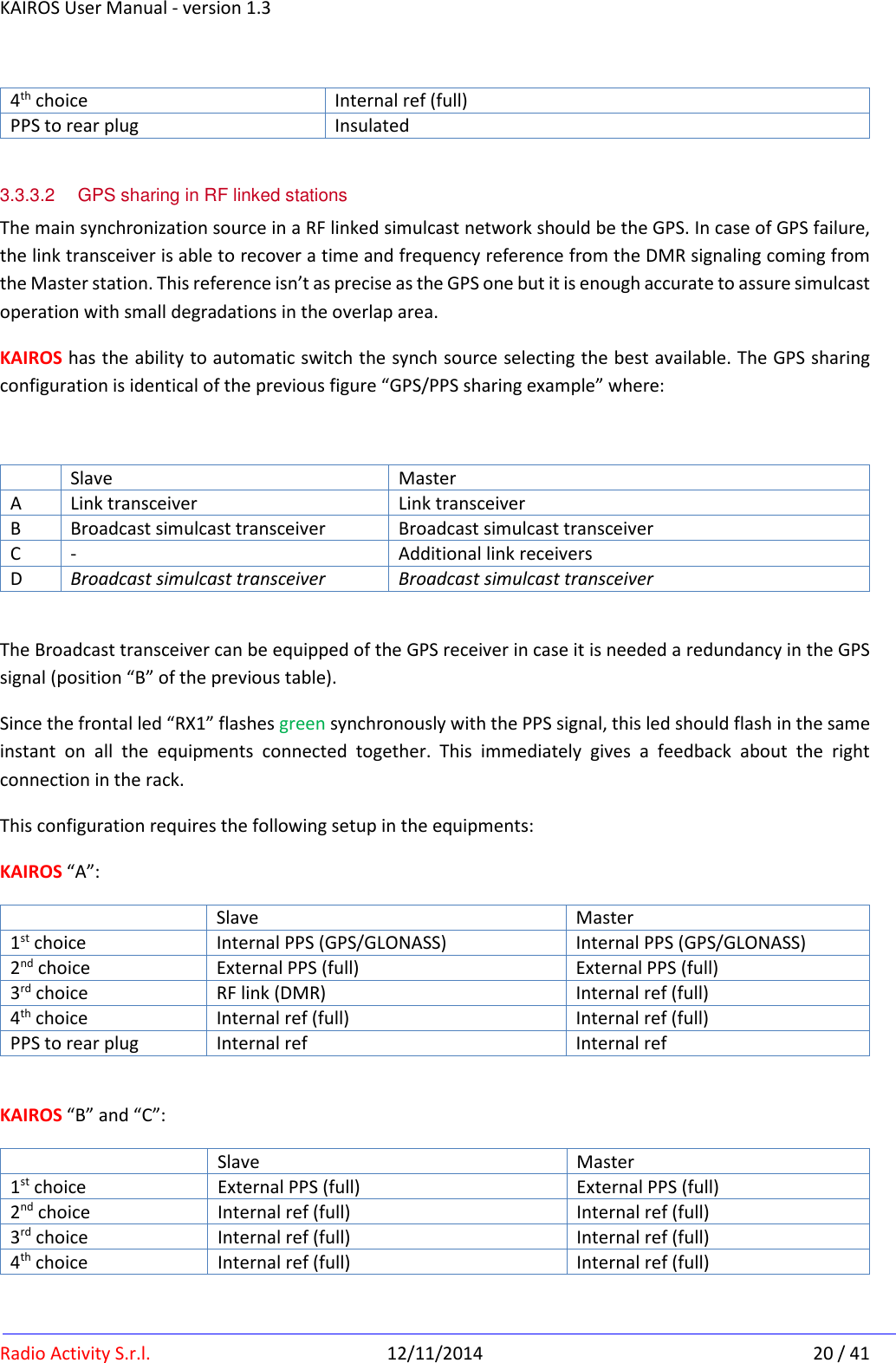
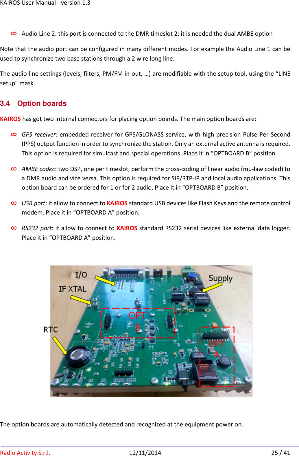
![KAIROS User Manual - version 1.3 Radio Activity S.r.l. 12/11/2014 23 / 41 3.3.5.1 Digital I/O The I/O output pins (PWR_GOOD, M_1, M_2, PTT_OUT_conn, I/O_OUT_1, ALR_OUT, FAN, OUT_1+1_MNG_CONN) are open collector type able to switch up to 20mA/40Vdc. A 470 Ohm resistor limits the maximum current and a 47K resistor refers the output to the internal 3.3V. The I/O input pins (REMOTE_OFF, E_1, E_2, I/O_IN_2, I/O_IN_3, ALR_IN1, ALR_IN2, PPS_IN_CONN) are internally pull-upped to the 3.3V. A pair of diodes protect the input from voltage below zero. This input switch on closing it to GND. The function of such pins are: REMOTE_OFF : [IN] it is equivalent to push the on/off button in the front of the equipment. When KAIROS is in on condition, closing this pin to GND for at least 3 seconds produces a switch off condition. When in off condition, closing this pin to GND for at least 250 milliseconds produce a switch on. See the Power on/off button description for further details using this pin. PWR_GOOD : [OUT] it is closed to GND when the equipment is regularly switched on E_1, E_2 : [IN] closing them to GND advise the equipment that a valid audio signal is incoming from the Line (like a PTT signal) M_1, M_2 : [OUT] they are closed to GND when a valid audio signal is sent to the Line (like a SQUELCH advise) I/O_IN_2, I/O_IN_3 : [IN] general purpose inputs; they can be used in special applications that need to acquire external status like: opening cabinet detection, opening site door, main power supply presence (with external switch) I/O_OUT_1 : [OUT] general purpose output; it can be used in special applications that need to set an external device/relays ALR_IN1, ALR_IN2 : [IN] alarm input; closing them to GND produces an alarm advise to the Supervisor Centre. Each alarm can be configured via the setup tool; it is possible to define a DMR TXT message or a SNMP trap for the 0 to 1 transition and for the 1 to 0. Typical application is the open site/cabinet event. ALR_OUT : [OUT] it is open from GND when the equipment detects an alarm condition. Power off is an alarm condition. FAN : [OUT] it is closed to GND when the temperature of the internal RF power amplifier rises above the threshold (typ 65°C). It can be used to switch on cooling fans in a cabinet. PTT_OUT_conn : [OUT] it is closed to GND when the transmitter goes on air. It is possible to insert a pre-time to allow the right switching on time to an external RF power amplifier. PPS_IN_CONN : [IN/OUT] this pin supports an external PPS signal or can share the internal PPS (from GPS receiver or from the PTP or from other sourced synch). As described previously, a bus connection between different co-located KAIROS realizes a multiple GPS reception with automatic backup. This pin can also be](https://usermanual.wiki/Radio-Activity-srl/KA450/User-Guide-2762869-Page-23.png)
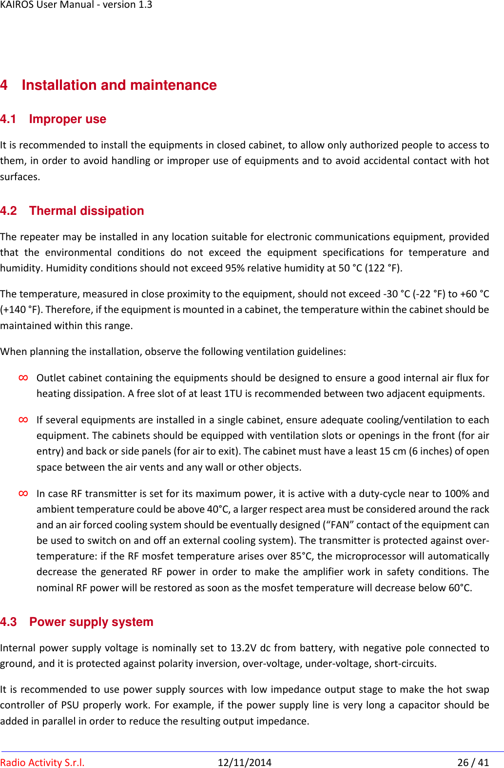
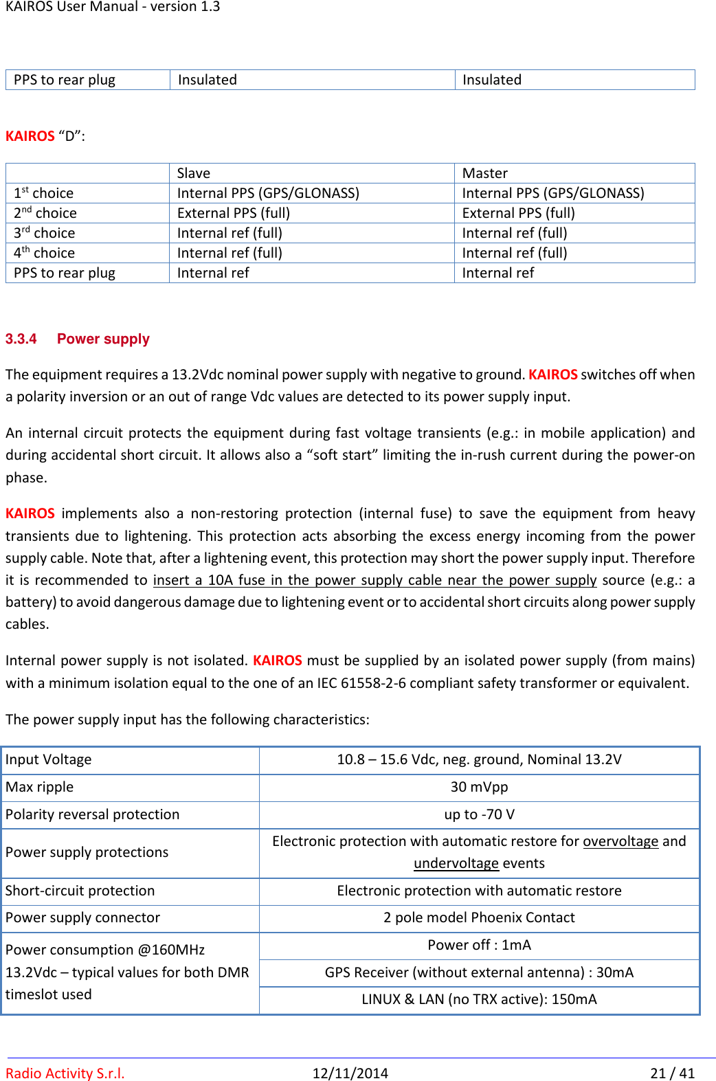
![KAIROS User Manual - version 1.3 Radio Activity S.r.l. 12/11/2014 24 / 41 configured to accept an external synchronous clock or an external pulse per second signal. Contact Factory for further details. IN/OUT_1+1_MNG_CONN : [IN/OUT] these pins support a simple protocol to allow two KAIROS to functioning as 1+1 (main and spare) equipment. V_ext_1 : [IN analog] not isolated inputs for voltage sensing (10KOhm / 0..24V referred to ground); the value of this voltage can be seen via the remote control tool. +12Vcc_TO_EXT : [OUT aux supply] this pin provides 13.2V, limited at 400mA, to supply a general purpose external device 3.3.5.2 Audio I/O KAIROS provides two 2/4 wires + E&M balanced interface for external audio devices like consoles or phone lines. These audio ports carry analog or DMR communications (in this case the AMBE codec option is requested). The inputs are IN_1A/IN_1B for the Audio Line 1 and IN_2A/IN_2B for the Audio Line 2 (Z_in = 20KOhm differential / 10KOhm single ended). The outputs are OUT_1A/ OUT_1B for the Audio Line 1 and OUT_2A/ OUT_2B for the Audio Line 2. These two outputs have different impedance: ∞ Audio Line 1 Z_out = 600 Ohm differential / 300 Ohm single ended. ∞ Audio Line 2 Z_out = 150 Ohm differential / 75 Ohm single ended. These IN/OUT ports are balanced and ground referred (NOT FLOAT! don’t apply to these pins more than 20Vdc). For long line use, it is recommended to insert an external 1:1 transformer in order to isolate the port from static voltage difference that can be arise between the line ends. They can be used as balanced (suggested method) or as single ended using only one of the IN/OUT pin. The nominal level of the audio signal in/out is -10dBm and can be regulated via setup tool between -20 and 0 dBm (-14 to -6dBm in single ended). These Audio ports, in conjunction with the E_1, E_2, M_1, M_2 I/O signals described before, realize a double 4Wire+E&M interface. In analog communications the standard settings of these ports are: ∞ Audio Line 1 is the audio port for Console; it is a PM (phase modulated = the incoming audio is emphasized) audio port ∞ Audio Line 2 is the audio port for External modem (e.g.: paging interface); this port is a FM (frequency modulated = the incoming audio is “flat”) audio port In digital communication, if the AMBE option board is installed, these ports have the following roles: ∞ Audio Line 1: this port is connected to the DMR timeslot 1.](https://usermanual.wiki/Radio-Activity-srl/KA450/User-Guide-2762869-Page-24.png)