Radio Activity srl RA-450 DMR REPEATER-UHF BASE STATION User Manual
Radio Activity srl DMR REPEATER-UHF BASE STATION
UserManual.wiki
>
Radio Activity srl
>
RA 450 User Manual
User Manual
Navigation menu
Upload a User Manual
Namespaces
Wiki Guide
HTML
PDF
Info
Views
User Manual
Discussion / Help
Navigation
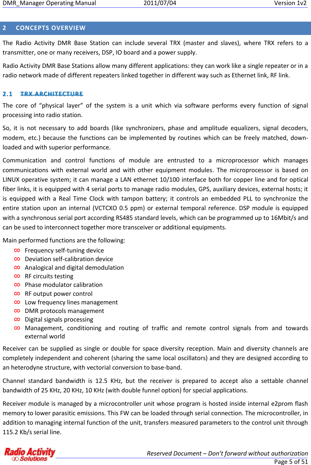
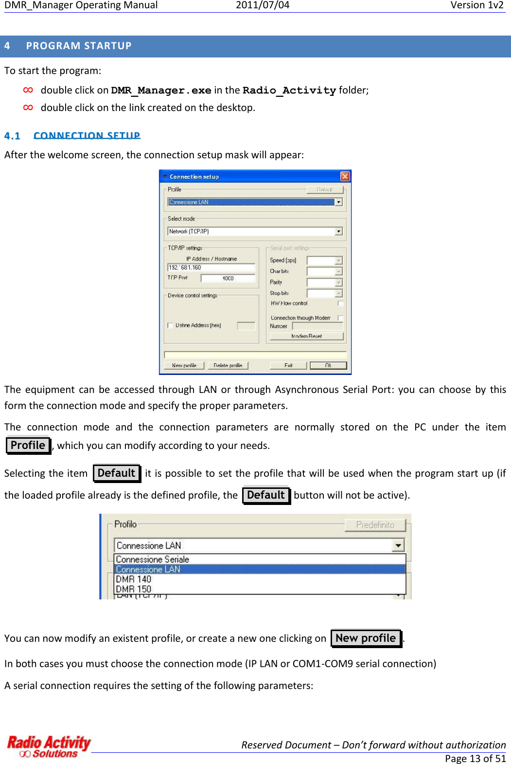
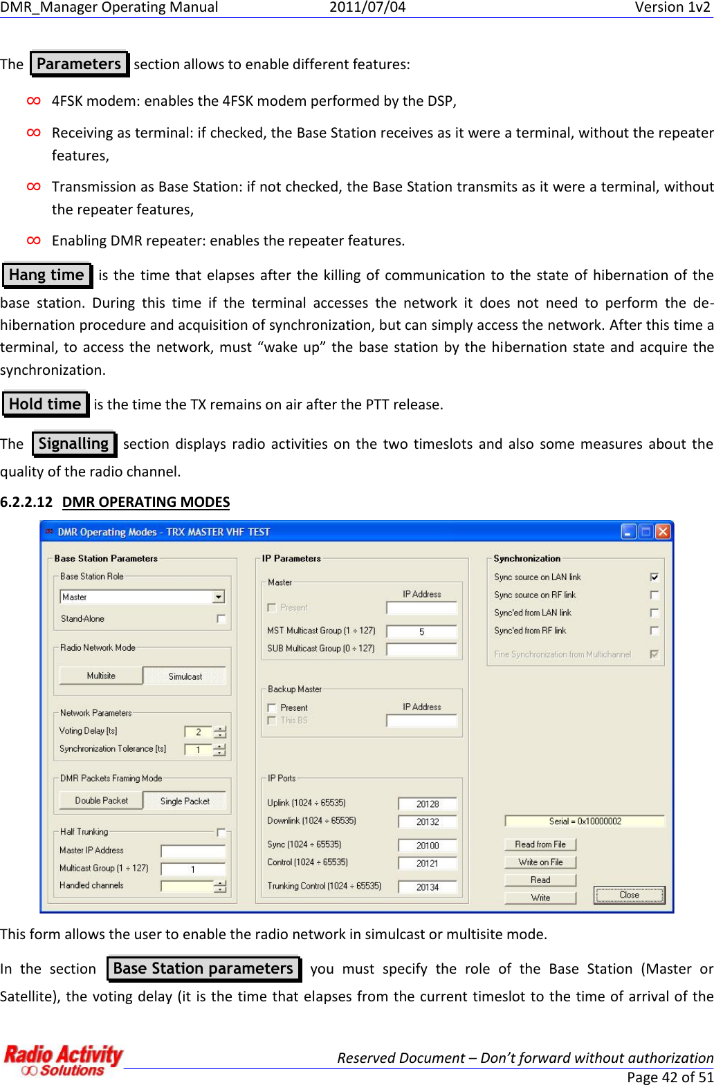
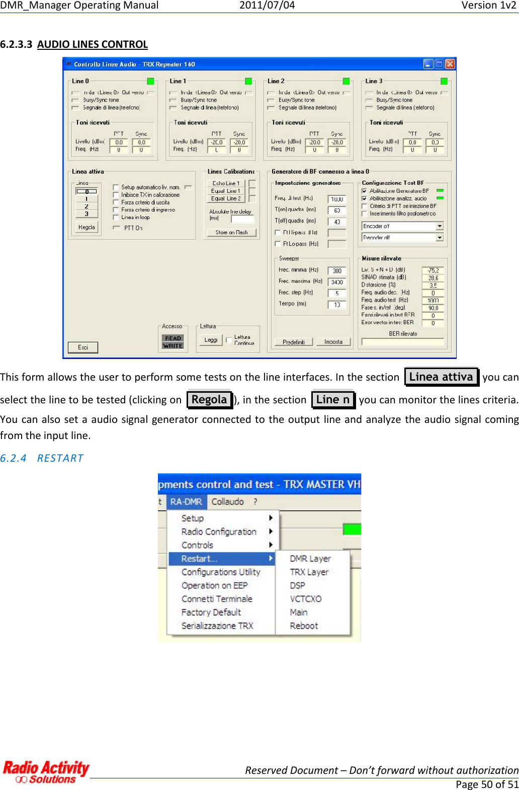
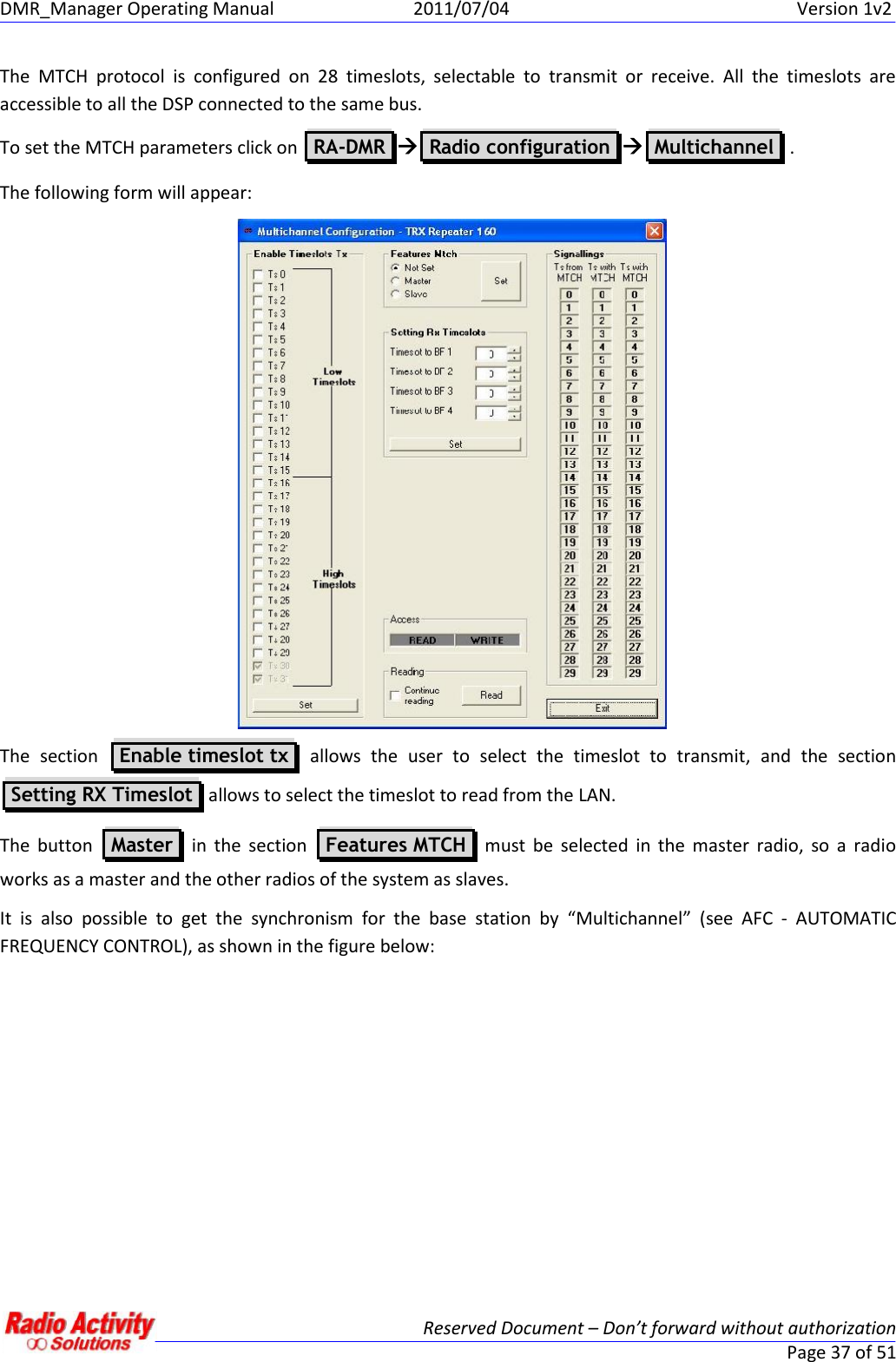
![DMR_Manager Operating Manual 2011/07/04 Version 1v2Reserved Document – Don’t forward without authorizationPage 29 of 51Channel nameChannel presentPresence of the channelChannel enabledEnabling of the channelTRX ModeIndicates all of the possible transmission mode allowed: Analog,compatible with ETSI standard, compatible with Motorola terminalsChannel spacing [KHz]Allows to choose the channel spacing: 25KHz, 20KHz, 12.5KHz, 10KHzTX Frequency [KHz]Transmission frequencyPrimary RX frequency [KHz]Receiving frequency of the primary receiverSecondary RX frequency [KHz]Receiving frequency of the secondary receiverTertiary RX frequency [KHz]Receiving frequency of the tertiary receiverSimplex frequency shiftIf set, when the TX is active, the RX frequency is shifted to avoidinterferences. This is meaningful only for simplex operating mode.TX power [W]Transmission powerMaximum continuous transmission [s]Maximum time allowed for continuous transmission (if 0, this optionis not active)Transmission closure delay [ms]Time before carrier off after the end of the communicationTX DCS code [oct]Allows to choose a DCS code to transmit (Octal notation)RX DCS code [oct]Allows to choose a DCS code to receive (Octal notation)TX TCS frequency [Hz]Allows to set a subaudio tone to transmitRX TCS frequency [Hz]Allows to set a subaudio tone to receiveRX emergency TCS frequency [Hz]Allows to set an emergency subaudio tone to receiveRX TCS hold time [ms]Time before TCS off after the end of the communicationSubaudio tone deviationSubaudio deviationSuperaudio frequency [Hz]Superaudio frequencyRX squelch level [dB]Allows to set a squelch opening levelRX squelch Hysteresis [db]Difference between squelch opening and closure levelsDMR colour code RX MainRX colour codeDMR colour code TX MainTX colour codeDMR colour code RX auxRX emergency colour codeDMR colour code TX auxTX emergency colour codeTo modify the channel parameters click on the column of the channel to modify…](https://usermanual.wiki/Radio-Activity-srl/RA-450/User-Guide-1569745-Page-29.png)
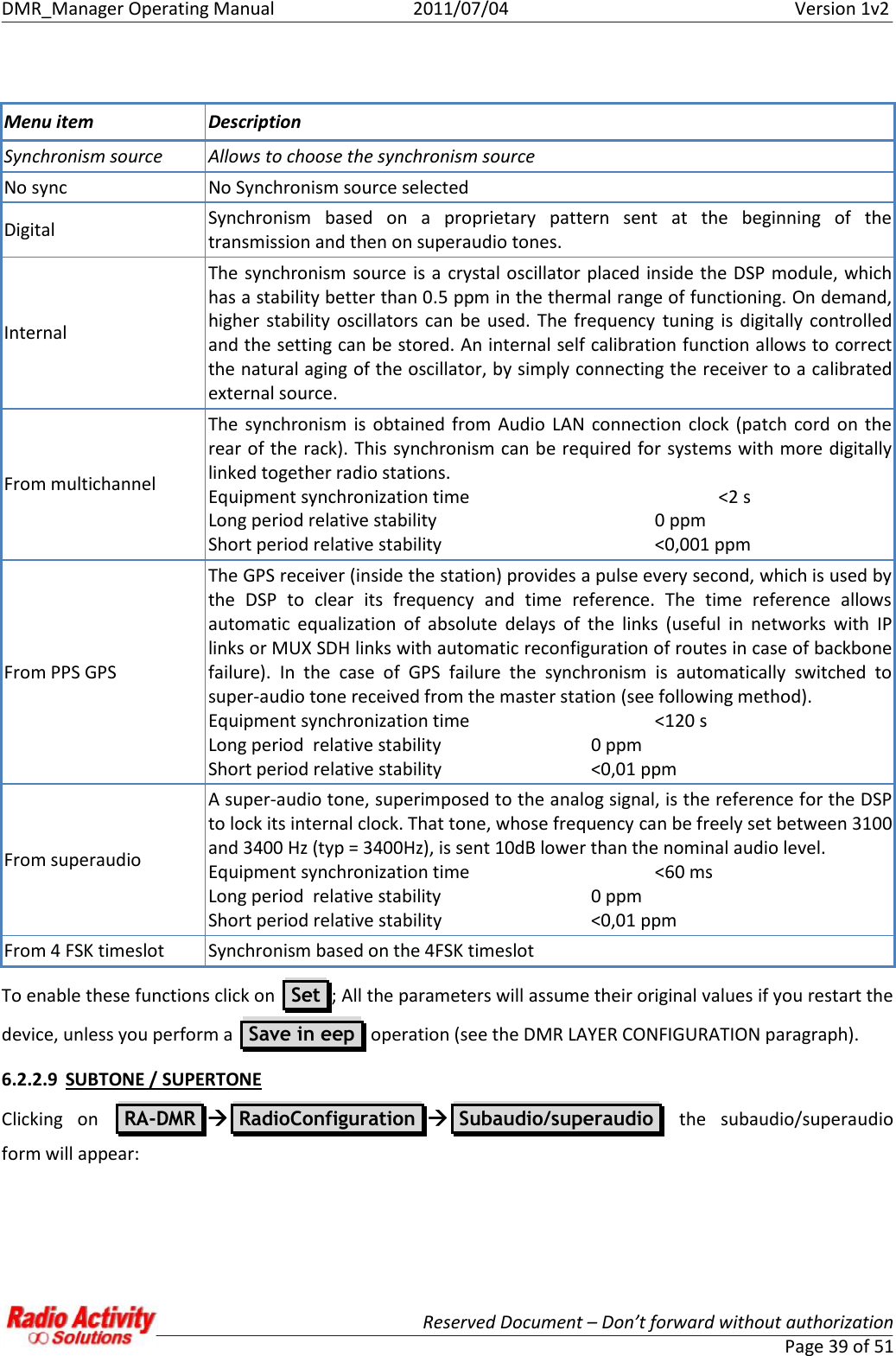
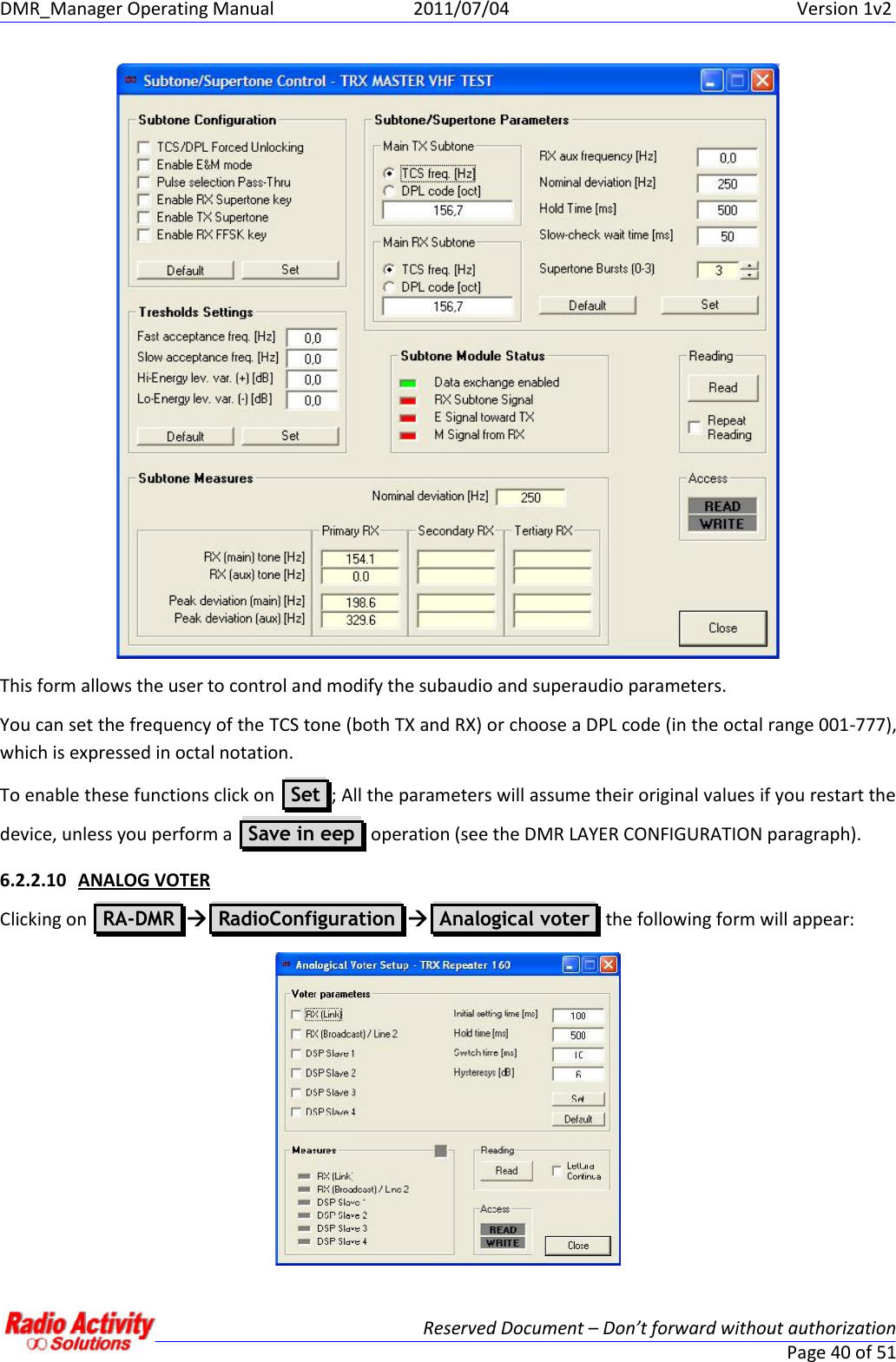
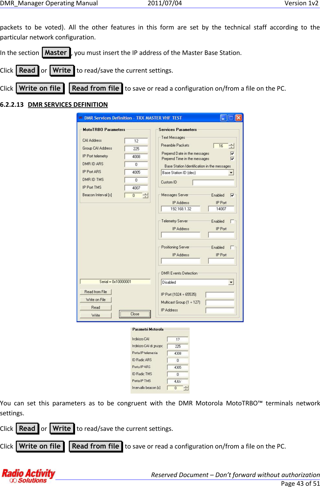
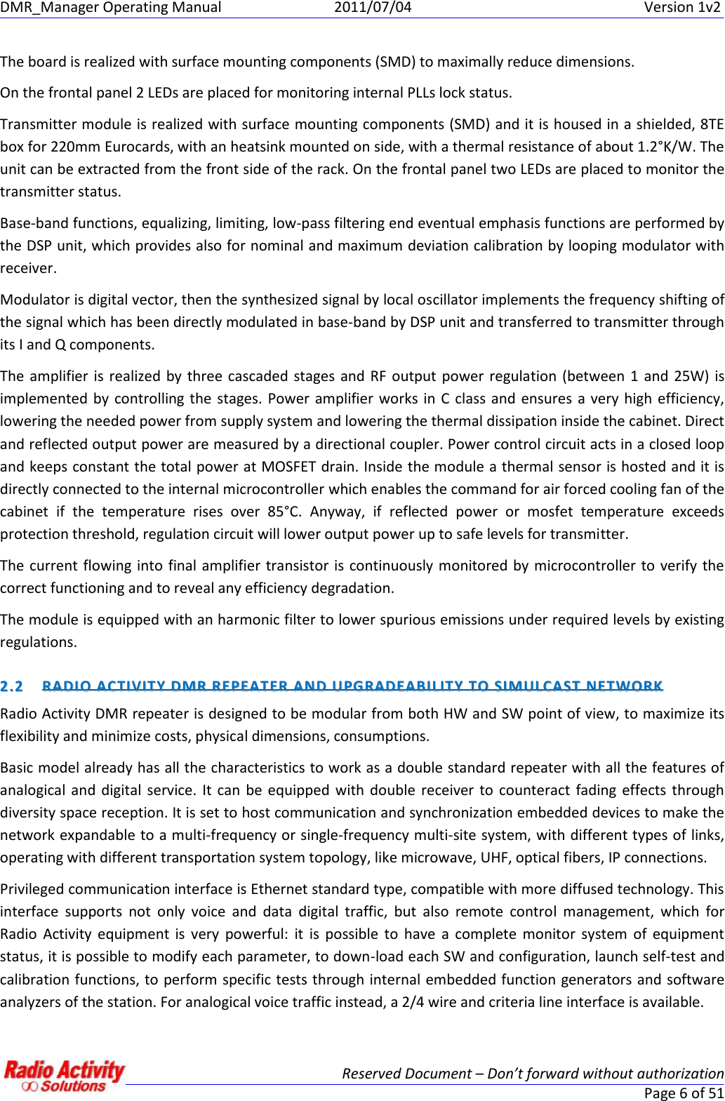
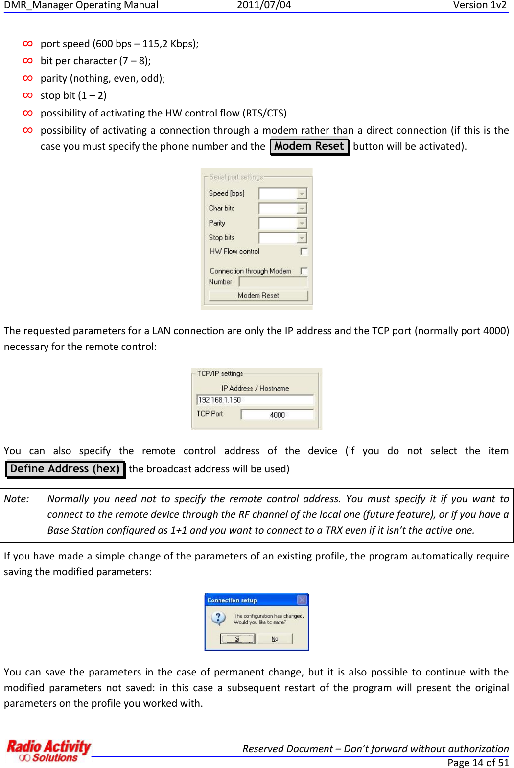
![DMR_Manager Operating Manual 2011/07/04 Version 1v2Reserved Document – Don’t forward without authorizationPage 41 of 51This form allows the user to set the analogical voter inputs (in the section Voter parameters ),In the Voter parameters section you can:∞choose the signal sources for the analogical voting and the related setting time,∞set the hold time for the voted source (that is the minimum time before source changing),∞set the switch time (that is the minimum time between source changing after hold time expiration),∞set the signal hysteresis (that is the signal threshold for a valid candidate source).You can set these parameters specifying the numbers in the section on the right: Initial settingtime [ms] is the searching time for the best signal initially, Hold time [ms] is the time the voted sourceis maintained. Switch time [ms] is the time step after which a different input can be voted as the “best”,Hysteresys [dB] is a threshold: if another signal is Hysteresys [dB] better than the currently votedone, that signal become the new voted one.To enable these functions click on Set ; All the parameters will assume their original values if you restart thedevice, unless you perform a Save in eep operation (see the DMR LAYER CONFIGURATION paragraph).6.2.2.11 DMR LAYER CONFIGURATIONDisplays the colourcodes set in thechannels tableDisplays the quality ofthe signal received onthe timeslotsIt indicatesactivity on theradio channelsThese parameters areset by the technicalstaff according to thenetwork configuration](https://usermanual.wiki/Radio-Activity-srl/RA-450/User-Guide-1569745-Page-41.png)