Radio Frequency Systems 48960 Bi-Directional Booster User Manual 602100023500rA
Radio Frequency Systems Inc Bi-Directional Booster 602100023500rA
Manual

Bi-Directional Amplifier
System
Part Numbers
48960
Operation and Installation Manual
200 Pond View Drive
Meriden, CT 06450 U.S.A.
Telephone (877) 737-9675 FAX (203) 821-3852
www.rfsworld.com
ITEM # 602100023500
DOCUMENT TYPE:
Operation and Installation Manual
REV: A
DOC #:
602100023
PAGE 2 OF 16
TITLE:
Bi-Directional Amplifier System
REV
C
OMPLETED
BY
APPROVED
BY RELEASE
DATE ECO # DESCRIPTION OF CHANGE
A L. ZHEN INTIAL RELEASE
Proprietary Note: The information contained in this document is considered confidential material proprietary to Radio Frequency Systems and is solely for
information purposes. The information shall not be used by anyone other than Radio Frequency Systems to design or construct any of the items depicted, nor
shall it be disclosed, duplicated, or copied for any purp
ose, nor made available to any third party without the prior written consent of a Radio Frequency Systems
official.

ITEM # 602100023500
DOCUMENT TYPE:
Operation and Installation Manual
REV: A
DOC #:
602100023
PAGE 3 OF 16
TITLE:
Bi-Directional Amplifier System
TABLE OF CONTENTS
GENERAL STATEMENTS
....................................................................................................................................................4
MAXIMUM PERMISSIBLE EXPOSURE LIMITS
.............................................................................5
PRODUCT OVERVIEW
............................................................................................................................................................6
FIELD TUNE-UP, ALIGNMENT OR CALIBRATION
............................................................................................................................6
FCC ID AND CANADA CERTIFICATION NUMBERS
.......................................................................................................................6
THEORY OF OPERATION
................................................................................................................................................................................7
BLOCK DIAGRAM
.............................................................................................................................................................................................7
ELECTRICAL SPECIFICATIONS
...................................................................................................................................................................8
MECHANICAL SPECIFICATIONS
................................................................................................................................................................8
ENVIRONMENTAL SPECIFICATIONS
.......................................................................................................................................................8
INTERMODULATION, POWER, AND AGC
............................................................................................................................................9
AGC SET POINT ADJUSTMENT
.................................................................................................................................................................9
AGC AUTOMATIC SHUTDOWN
..............................................................................................................................................................10
MANUAL GAIN ADJUSTMENT
.................................................................................................................................................................10
AC/DC POWER
................................................................................................................................................................................................10
GROUNDING AND SURGE PROTECTION
.............................................................................................................................................10
INSTALLATION
.................................................................................................................................................................................11
ANTENNA ISOLATION
...................................................................................................................................................................................12
DIAGNOSTICS/TROUBLESHOOTING
...........................................................................................................13
TEST POINT DESCRIPTIONS
.......................................................................................................................................................................13
FACEPLATE
.........................................................................................................................................................................................................14
COMPONENT LOCATION
................................................................................................................................................15
MAINTENANCE, REPAIR AND WARRANTY
.....................................................................................16
PERIODIC MAINTENANCE
..........................................................................................................................................................................16
ORDERING AND RETURNING COMPONENTS
...................................................................................................................................16
LIMITED WARRANTY
...................................................................................................................................................................................16
ITEM # 602100023500
DOCUMENT TYPE:
Operation and Installation Manual
REV: A
DOC #:
602100023
PAGE 4 OF 16
TITLE:
Bi-Directional Amplifier System
General Statements
Thank you for selecting this RFS product. We are confident that you will find this product in proper
working order and meeting all stated specifications. If not, please contact customer service
immediately at 1-800-321-4700 and we will resolve the issue without hesitation.
Please read this manual. A full understanding of product operation will support optimal performance
and prevent accidental damage not covered by the stated warranty.
Do not operate this product without proper loads on both antenna ports. You must connect
both antenna ports to an antenna or a 50-Ohm load, rated for at least 1 watt.
These products receive and amplify RF signals. As such, these products are intended for use
by the licensee of the respective service and should not be used without the expressed
permission of the licensee.
Do not remove the cover for service. There are no internal adjustments. Path manual gain
adjustment access holes are clearly marked on the bottom. Under normal circumstances,
you need not make any adjustments. For more information, see installation section.
The terminology “RX” and “TX” are being replaced by “UL” for uplink and “DL” for downlink
respectively.
The 48900 series bi-directional amplifiers/ repeaters/signal boosters are designed and optimized for
low cost, high reliability, and ease of use. This manual provides information on the proper operation
and care; however, Radio Frequency Systems can provide the total package of components and
hardware for any type of repeater installation. See our catalog for the full line of antennas, coaxial
cables, and accessories at www.rfsworld.com. To achieve the best possible coverage, contact RFS
Applications Engineering at 1-800-659-1880 for technical assistance and/or design of the distribution
network.
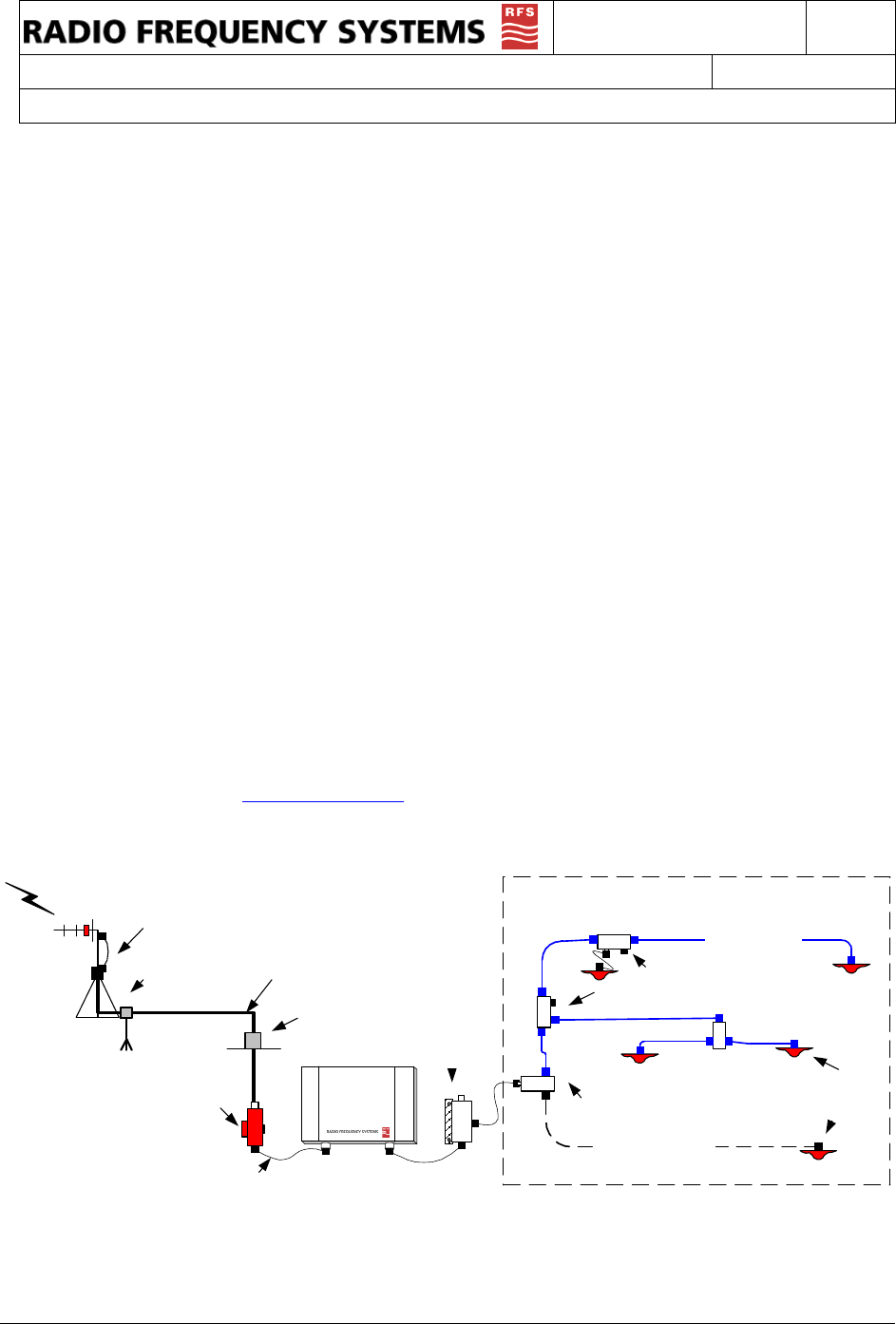
Ground Kit
Wall/Roof
Feedthrus
1/2" or 7/8"
Coaxial cable
Surge
Assestor
Jumpers
Base Service
Donor
Antenna
In-band or
Crossband
Combiners
MBC-
2-1
A
B
C
Distribution Network 800-2500 MHz
2
10
2
6
1/2" Plenum Coax
1/2" Plenum Radiaflex
Splitters, 2, 3 or 4 way
Couplers, 6, 10, 15 or 20 dB
In building
Antennas
For distribution network design assistance, contact RFS Applications Engineering at 1-800-659-1880.
ITEM # 602100023500
DOCUMENT TYPE:
Operation and Installation Manual
REV: A
DOC #:
602100023
PAGE 5 OF 16
TITLE:
Bi-Directional Amplifier System
Maximum Permissible Exposure Limits
THIS PRODUCT IS CATEGORICALLY EXCLUDED FROM ROUTINE ENVIRONMENTAL
EVALUATION ACCORDING TO CFR 47, SECTION 1.1037.
Signal repeaters like the 48960 bi-directional amplifier generate radio signals and thereby give rise to
electromagnetic fields. The installer is expected to have a complete understanding of CFR Title 47,
Sections 1.1307 and 1.1310. A brief discussion follows but is not intended to be a substitute.
Additional information can also be obtained from OET Bulletin 65.
Antenna installation should be performed by qualified technicians only.
Installation instructions are not optional and are for the purpose of satisfying FCC RF
Exposure Compliance.
All antennas (donor and service) are to be fixed-mounted and physically secured to
one location.
Non building-mounted donor antennas must be greater than 10 meters above ground.
Maximum gain for the donor antenna is 28 dB.
Maximum gain for service area antenna(s) is 11 dB + network losses.
Minimum separation to any body part of any person is 25cm.
There are two types of antennas attached to this unit. The donor antenna is typically roof mounted
and the service antenna is usually mounted in a publicly accessible area. Both antennas should be
fixed mounted. Installation considerations for both of these will be discussed separately.
Donor antennas receive the base site TX signals and transmit the mobile TX signals back to the base
site (uplink paths). These are typically mounted on rooftops or tower structures. The maximum output
power of the uplink path is less then 80 mW (+19dBm). Section 1.307(b)(1) excludes from routine
environmental evaluation, facilities, operations and transmitters that, according to Table 1 (titled
"Cellular Radiotelephone Service"), are less than 1000W ERP for building mounted antennas and
less than 1000W and greater than 10 meters above ground for non building-mounted antennas. As
such, with maximum power from the uplink path at 80 mW (+19dBm) and a maximum antenna gain
of 28 dB, the donor antenna installation will not exceed 1000 Watts (+60 dBm) and is categorically
excluded.
However, according to Section 1.1307 (b)(1), the appropriate exposure limits of 1.1310 are applicable
to all facilities, operations, and transmitters. Therefore, the MPE (Maximum Permissible Exposure) of
Section 1.1310 applies to the donor antenna installation. OET Bulletin 65 provides methods of
calculating power density based upon the ERP and distance. It would be impossible to cover every
possible configuration in this manual. Likewise, it would be unreasonable to dictate the exact
parameters of every installation; therefore, it is the responsibility of the qualified technician to know
and ensure that Sections 1.1307 and 1.1310 of CFR Title 47 are being met.

ITEM # 602100023500
DOCUMENT TYPE:
Operation and Installation Manual
REV: A
DOC #:
602100023
PAGE 6 OF 16
TITLE:
Bi-Directional Amplifier System
Service antennas are also fixed mounted and covered by the same MPE considerations as the donor
antenna. However, this assumes that the area is always general population/uncontrolled and that the
minimum distance in most installations will be less than 3 feet. According to Table 1(B) of Section
1.1310, the power density at 894 MHz is 0.596 mW/cm2. The maximum output power in the 48960
downlink (base to service area) is less then +19 dBm (80 mW). Assuming no feeder cable loss and a
service area antenna gain of 11 dB, a safe minimum separation of 10 inches (25 cm) is required to
stay within the MPE.
1.05 x 1000 mW/3.14 x 252 = 1050/1962.5 =0.535 mW/cm2
Therefore, the service area antenna should be mounted such that no body part of any person may
come closer than 10 inches (or 25 cm). The service area antenna gain is 11 dB in the example
above, but may be increased to make up for cable and/or splitter or tap losses. For example, if a 2-
way splitter is used to provide for two antennas in different parts of the service area, then the antenna
gain may be increased to 14 dB to make up for the loss of the splitter 3.6 dB. The maximum service
area antenna gain for any specific location can be calculated as follows: 11 dB+ accumulated losses
to the antenna.
Product Overview
Field Tune-up, Alignment or Calibration
There is no field tune-up or calibration necessary for the 48960 bi-directional amplifier. These units
are aligned and calibrated at the time of manufacture and are designed to retain calibration
throughout the life of the product. Manual gain adjustment is provided to optimize the installation and
discussed in Section 10.
FCC ID and Canada Certification Numbers
The listed models have been tested and granted certification by the FCC in accordance with CFR
Title 47, Part 90 and by the DOC in accordance with RS 131, Issue 131.
The FCC identification number for each particular model appears on a label on the faceplate of the
unit. Applicable FCC identification and Canadian ISC numbers are as shown:
FCC ID Canada
IWD48960 1634B-48960
ITEM # 602100023500
DOCUMENT TYPE:
Operation and Installation Manual
REV: A
DOC #:
602100023
PAGE 7 OF 16
TITLE:
Bi-Directional Amplifier System
Theory of Operation
The 48960 BDA is designed to enhance radio communication in buildings, basements, tunnels and
other RF shielded environments. The 48960 is a dual band BDA that will amplify both the 800 and
900 SMR as listed in the electrical specifications
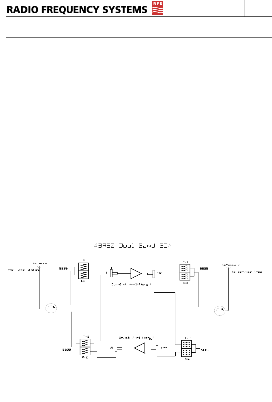
These units work by receiving and amplifying the base TX signals via a donor antenna directed at the
desired base site. This RF path is called the downlink. The amplified base TX signal is re-radiated via
antenna(s) or radiating cable into the Service Area. Subscriber mobile RF signals are received by the
same service area radiating elements and amplified in the uplink RF path to be radiated back to the
base via the donor antenna.
The uplink and downlink amplifiers are broadband to accommodate all the channels in the passband.
Differentiation is provided by the duplexing filters. These determine the basic pass band and prevent
oscillation between the uplink and downlink by attenuating the opposing link frequencies.
Both the downlink and uplink gain paths have Manual and Automatic Gain Control (AGC) to prevent
an overdrive condition. The AGC set point is factory set so that the output of the link will not exceed
FCC limits for spurious emissions (-13 dBm). Further discussion is provided in page 10.
The control board distributes DC power to the amplifier modules and monitors each module for any
fault conditions. LED indicators provide visual diagnostics; two Green LEDs indicate AC power (one
each for the uplink and downlink RF board), a single Red LED for summary fault indication, yellow
AGC LEDs indicate overdrive in the respectively link. A relay terminal provides connection to a NC /
NO relay for remote notification for any fault condition and a remote shut down feature.
Block Diagram
ITEM # 602100023500
DOCUMENT TYPE:
Operation and Installation Manual
REV: A
DOC #:
602100023
PAGE 8 OF 16
TITLE:
Bi-Directional Amplifier System
Electrical Specifications
Downlink Uplink
48960 Freq, MHz 851-869 806-824
Freq, MHz 935-941 896-902
Gain** 65 dB 65dB
Gain Flatness, typical** ±2.0 dB ±2.0 dB
Manual Attenuator Range >20 dB >20 dB
Output Limiter Range, Automatic* >20 dB >20 dB
Noise Figure, typical** 5.0 dB 5.0 dB
Composite Power, typical* +19 dBm +19 dBm
Impedance 50 Ohms 50 Ohms
VSWR, input 2.0 2.0
Propagation Delay, worst case at band edge <0.5 microsecond <0.5 microsecond
Power, 120/220 Auto Ranging, IEC-320 Socket 110 VAC@ .2 A
20dB band width, typical 26Mhz for 851-869
12Mhz for 935-941 26Mhz for 806-824
12Mhz for 896-902
*AGC circuitry monitors the output power and reduces the gain to prevent overdrive and oscillation.
**No attenuation and at room temperature.
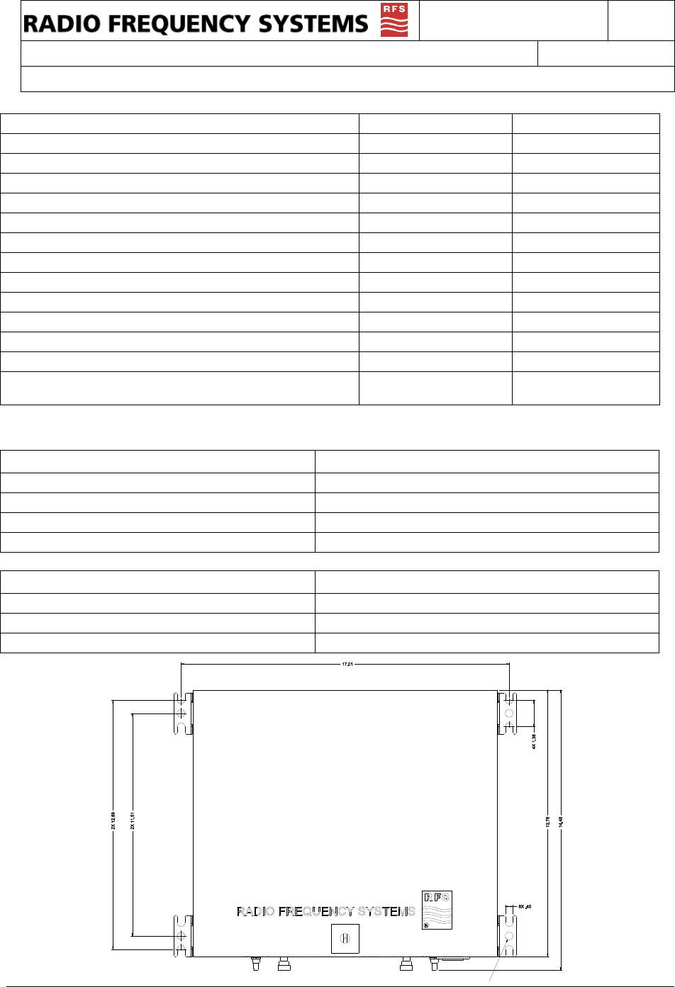
Mechanical Specifications
Connectors, RF N Female
Weight 40 lbs
Size, L x W x D 15.78 x 13.75 x 6.1 Inches
Diagnostics Power, AGC Overdrive, and Fault LEDs
Environmental Specifications
Operating Temperature, ambient -10 to +45 °C
Maximum humidity 95% RH (non condensing)
Environmental Rating Similar to NEMA 3R
ITEM # 602100023500
DOCUMENT TYPE:
Operation and Installation Manual
REV: A
DOC #:
602100023
PAGE 9 OF 16
TITLE:
Bi-Directional Amplifier System
Intermodulation, Power, and AGC
FCC requires that spurious emissions be less than {43+ 10 Log 10 (Power Out Watts)} dB below the
carrier Power Out (dB) level. This is always equivalent to -13 dBm. The primary contributor to
spurious emissions is multiple signal intermodulation. As multiple signals are amplified, they generate
intermodulation products (IM). The level of IM is a factor of the amplifiers linearity or 3rd Order
Intercept Point (IP3), and the number and power of signals being amplified (Pout).
IM = 3xPout - 2xIP3
The 48900 signal boosters use a combination of low distortion amplifiers and automatic gain control
(AGC) to achieve maximum output while automatically limiting spurious intermodulation levels to -13
dBm. A detector on the output of the amplifier provides a DC voltage proportional to the output
power. This voltage is compared to a factory setting. As long as this voltage is less than the setting,
no action is required. However, when the combination of signal level and or number of signals
causes the composite power to exceed the safe level, the AGC's comparator generates a DC voltage
to a pin diode attenuator that increases attenuation in proportion to the level of the DC voltage.
The attenuation reduces the output power until the detector voltage is at a safe level again. If the
number or power of the signals is reduced, the DC offset voltage will reduce the level of attenuation.
In typical operation, the AGC is only active when needed to prevent overdrive. If the AGC is
constantly activating, RFS suggests that you reduce the gain via the manual attenuator and verify
that an oscillation between the base and service antenna systems does not exist.
AGC Set Point Adjustment
A small hole (close to the RF connectors) in the top of the amplifier enclosure (DL and UL
respectively) provides access to the AGC set point. A potentiometer adjustment tool can be used to
increase the set point for approximately 5 dBm higher output power. Remove power and turn the pot
clockwise slowly until the stop is reached. This will increase the set point but retain the AGC to
protect the FCC certification and the BDA itself from damage due to runaway oscillation.
TABLE 1: TYPICAL OUTPUT POWER PER SIGNAL
Table 1 lists the typical
output power per signal,
which can be expected
from the 48900 for a
given number of active
signals operating at
equal input levels. For a
donor site that has 8 signals, the power per signal would
be +7 dBm, assuming the incoming signal is sufficient
so that that level will be achieved. Output power is
never greater then input power + gain of the BDA.
CAUTION
Remove power to the BDA. Increasing the set point of the AGC may result in interference. Use only
a non-conductive potentiometer tool to prevent damage to surrounding circuitry.
iDEN signals dBm
1 19.0
2 16.0
4 12.0
8 9.0
16 6.0
ITEM # 602100023500
DOCUMENT TYPE:
Operation and Installation Manual
REV: A
DOC #:
602100023
PAGE 10 OF 16
TITLE:
Bi-Directional Amplifier System
AGC Automatic Shutdown
If the attenuation capability of the AGC circuitry is exceeded, power to the power amplifier stage is
shut down to prevent harmful distortion and potential damage to the 48960. Shutdown will occur if the
AGC control limit is exceeded for about 1/2 second. Power is then cut for two seconds. After this
timeout, power is brought back on-line. If the overload condition is still present, shutdown will again
occur in approximately one second. This cycle will be repeated until the condition is removed.
Conditions that can cause AGC to shut down include the presence of one or more very strong
channels, a strong in-band noise source, or amplifier oscillation due to inadequate antenna isolation.
Manual Gain Adjustment
The independent manual attenuators, RX for uplink and TX for downlink, are accessible from the
faceplate on the bottom of the unit. These are pre-set in the fully counterclockwise position, at
minimum attenuation, maximum gain. Manual attenuation is separate from the AGC attenuators. At
the full clockwise position, >20 dB of attenuation will be introduced in the respective gain path.
Calibration is provided in dBs of attenuation. Resultant gain is full gain (63-67 dB) – the number
indicated by the attenuator setting. To lock the setting on either attenuator, a M3 screw is included
with this manual. Insert and tighten the screw in the spacer on the attenuator (inside unit).
AC/DC Power
AC power is supplied through a standard 3-wire male plug connected through a standard IEC-320
plug. Connect this plug to any standard 3-wire 120-240 VAC outlet. A 5x20 mm, .315 amp 250VAC
slow-blow fuse is used.
A 2
amp, 32 VDC, fast-acting
fuse is located on the side of each amplifier to
protect the DC voltage path. (See “Component Location”)
⌦ Always unplug the amplifier before servicing the interior.
⌦ Never insert conductive objects into any opening.
⌦ Never remove or probe under the plastic safety shield covering the AC terminals of the 24
VDC power supply.
⌦ Always use a standard 3-wire electrical outlet, with safety ground, for connection to AC
power.
Grounding and Surge Protection
The unit is case grounded through the three-prong plug. The donor antenna feeder cable should
have a cable ground attached to it, along with an inline surge arrestor between the donor antenna
and the 48960. The distribution network need not be grounded in building installations. However, the
distribution network in tunnels, subways or outdoor installations should also include a cable ground
and inline surge arrestor at or near the “service” port.
DANGER
Always remove power before checking or changing fuses. 120VAC can be lethal.
ITEM # 602100023500
DOCUMENT TYPE:
Operation and Installation Manual
REV: A
DOC #:
602100023
PAGE 11 OF 16
TITLE:
Bi-Directional Amplifier System
Installation
Choose an optimal location. The choice of a location for the 48960 to reside is often
dictated by circumstance. These units can withstand a wide range of environmental
conditions, but a cooler environment will increase the life of the product. The 48960 is not
intended for outdoor operation without environmental protection. A central location to
minimize cable loss in any leg of the distribution network is ideal. In addition, a stacking room
near a riser for easy access to the roof and other floors will facilitate the installation.
Mount repeater upright, with the connections toward the floor. Ensure there is sufficient
space above and below the unit to allow airflow through the heat sink. Check to make sure
the AC power cord can reach the power source. Also, provide adequate bending radii for the
coaxial cables.
Install directional donor antenna and align with desired base site. A directional yagi,
corner reflector or panel antenna is highly recommended. The 48960 has filtering to prevent
out-of-band signals from causing interference; however, it is best to reduce the potential for
interference by directing the mobile signals only towards the desired base site.
Check the incoming donor signals. A spectrum analyzer is recommended to confirm that
the desired base TX (DL) signals are strong enough to achieve the desired output power.
Also check for strong undesired signals in the pass band or on the pass band edge; these
may cause overdrive and AGC gain reduction. The donor antenna may need to be realigned
to optimize the signal levels.
Install service area antenna(s). Determining the location and type of service area antennas
is part of the distribution system design. Generally, it is desired to minimize the amount of
coax that has to be installed. However, in buildings with extensive obstructions, it may be
necessary to install several service area antennas. For assistance with antenna placement,
contact RFS Applications Engineering.
Connect service antenna(s) to "Service" port via a 50-ohm coaxial cable. Multiple
service area antennas/radiating cable runs may be connected to the 48960. Splitters and
taps may be used to accommodate unique distribution systems. Size and type of cable are a
matter of choice. Typically, 1/2" Flexwell foam coax is used, plenum rated for inside buildings
and work areas. However, 7/8" cable may be used to reduce longitudinal loss. Superflex
cables are easier to install but have higher longitudinal loss. Fiber optic distribution systems
may be used with the 48960. Observe the input power requirements of the manufacturer.
RFS has all the components needed to complete even the largest installations. Visit our
website at: www.rfsworld.com, or call us.
WARNING
Do not connect AC power until antennas have been connected to both the base and
service area ports.
IMPORTANT
Observe Maximum Permissible Exposure cautions when determining the type and
location of all antennas.

ITEM # 602100023500
DOCUMENT TYPE:
Operation and Installation Manual
REV: A
DOC #:
602100023
PAGE 12 OF 16
TITLE:
Bi-Directional Amplifier System
Connect the service area antennas to the “Service” port.
Connect the donor antenna cable to "Base" port.
Connect AC power to the unit and observe power and fault LEDs
Ideally, a spectrum analyzer should be used to confirm the DL signal at the service port.
However, the 48960 has diagnostics to assist with optimization as discussed below.
Confirm the green “PWR” LEDs are lit in both the uplink (UL) and downlink (DL) and that the red
“Fault” LED is not lit. If the yellow DL AGC LED is lit then it is suggested to reduce the gain in the
DL via the manual attenuator. Turn the adjustment clockwise to reduce gain until the AGC LED
goes out. Then adjust the UL gain to the same setting to minimize noise generated in the uplink
and balance the links.
If both LEDs are lit then there is likely an oscillation between the antennas – see “Antenna
Isolation”. Also read the section on “Intermodulation, Power, and AGC”
Test the coverage.
Ideally, this test should include multiple subscribers in various locations of the service area. It
should also include one subscriber in close proximity to the 48960. This test will check to ensure
that a nearby subscriber does not overdrive the uplink and reduce coverage for the other users.
If the UL AGC LED lights during the system test it most likely indicates that there is a hot spot in
the service area, where the subscriber signal is overdriving the uplink. It is best to minimize this
effect by relocating the nearest service antenna or adding an attenuator pad to reduce the UL
signal strength. In some cases, a coupler may be needed to add a low power antenna in specific
locations. For this reason it is best to have extra antennas, splitters, couplers and coax.
Antenna Isolation
Isolation between the donor (base) antenna and service area antenna should be 20 dB greater
than the gain of the repeater amplifier.
If the isolation is less than the amplifier gain, then positive feedback sufficient for oscillation is present
in the system. Such oscillations will overdrive one or both amplifier links and continuously activate the
AGC auto-shutdown circuitry.
Antenna isolation is usually not a problem for in-building installations. Isolation is improved by using a
directive donor antenna and facing it away from the distribution or service antenna(s). Decoupling is
achieved by spatially separating the antennas vertically and/or horizontally. Other factors influencing
isolation include multi-path reflections, structures, other antennas, passing vehicles, personnel
proximity, etc.
It is always best to measure the isolation before connecting the repeater. The most direct way to
measure the isolation is to inject a known signal into one antenna, and measure the coupled
signal at the other antenna. This should be done across the applicable bandwidth to account for
the frequency dependency of standing waves.
ITEM # 602100023500
DOCUMENT TYPE:
Operation and Installation Manual
REV: A
DOC #:
602100023
PAGE 13 OF 16
TITLE:
Bi-Directional Amplifier System
Oscillation may also take place between the 800 SMR band and a system for amplifying the 800
Cellular band. Contact RFS applications engineering for assistance.
Diagnostics/Troubleshooting
Test Point Descriptions
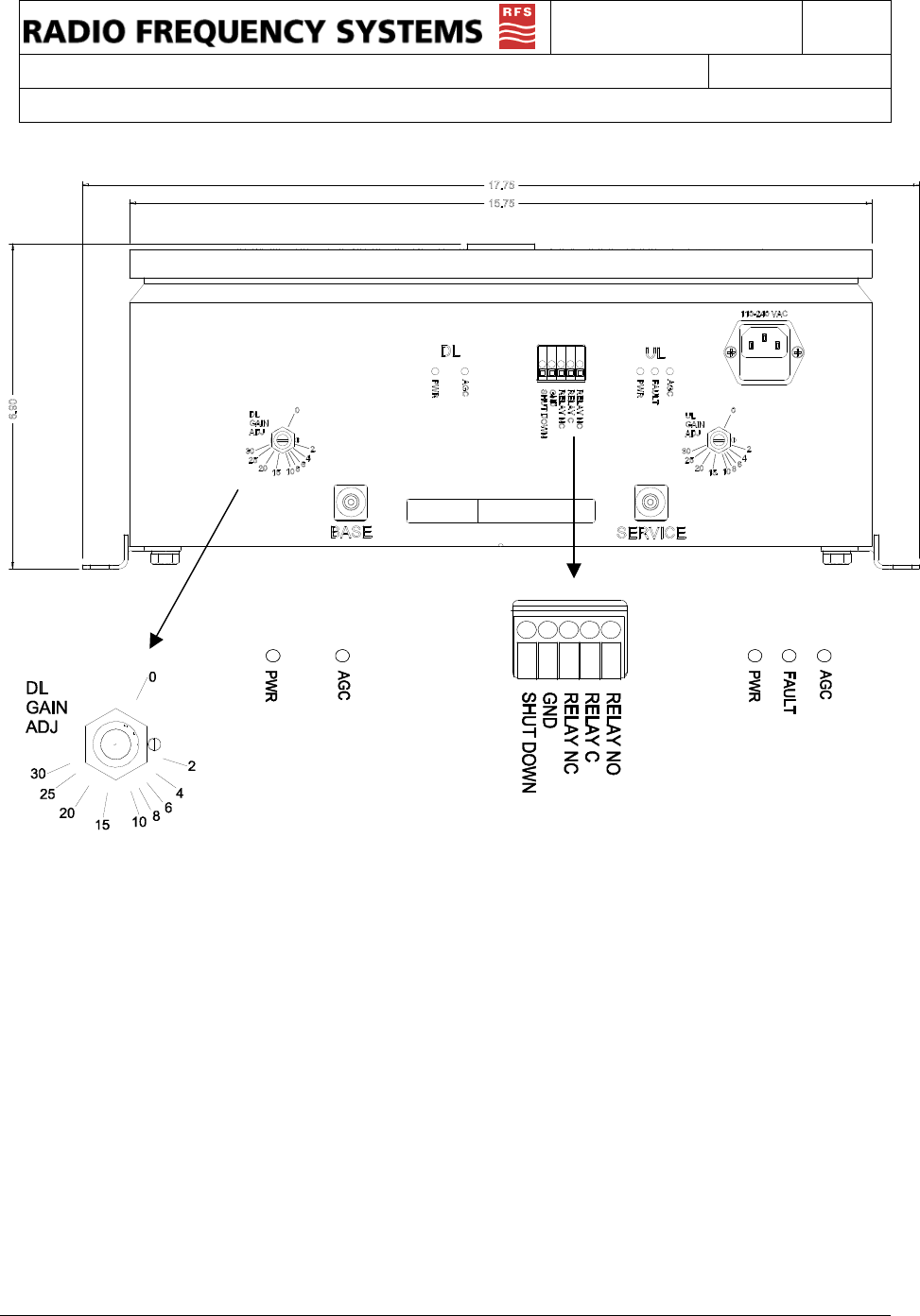
• Green power LED indicates DC voltage is applied to the respective link.
• Yellow AGC LEDs indicate AGC is active in the respective link
• Red Fault LED indicates that a under or over current condition exists or that the AGC Shut Down
circuitry has been activated.
• Relay NC (normally closed), C (common), NO (normally open) is a summary fault relay that
changes state whenever the fault LED is lit or when the power fails. This relay is rated for up to 48
VDC at 2 Amps.
• Shut Down pin will cause the 48960 to shut down when it is connected to GND (ground). Current
draw is insignificant.
Problem: Solution:
Green power LEDs on faceplate not
lit.
Check power source and the AC fuse located in the EIC plug.
Check the DC fuse located inside the 48960 on the side of the
individual amplifier modules. Check connections to the
internal power supply.
Red LED on faceplate is lit.
First, try to cycle the power then watch the AGC LEDS to
make sure the unit is not in AGC shut down. If the Fault LED
is cycling then an overdrive condition exists. See AGC
Automatic Shutdown section.
Green power LED lit and no red Fault
LED on faceplate; unit does not
appear to be working.
Check for a break in the donor or distribution networks. Also,
check to ensure the donor signal is still available to the
repeater. An obstruction could be blocking the donor base site
or the donor antenna could have become misaligned. Then,
check the integrity of the distribution network. Coaxial cable
has a minimum bending radius, if that is exceeded the inner
conductor may crack or break causing excessive reflections to
the signals.
Yellow AGC LED is lit.
AGC LEDs indicate an overdrive condition in the respective
link. Reduce the respective link gain via the Gain Adjust until
the LED goes out. Generally, the opposing link gain should be
adjusted to approximately the same setting. If the LED does
not go out, then the input signal is too strong. Sweep the input
to the respective link to identify the source of overdrive. If the
signal is not a desired signal then external filtering should be
considered to attenuate. If the signal(s) are all desired then
attenuate the base port with a 10 dB in-line attenuation pad.
IMPORTANT
The 48960 BDAs are not designed for field repair. The outer cover may be removed for
some troubleshooting but under no circumstances should the covers be removed from
the internal amplifier modules as this will void the warranty.
ITEM # 602100023500
DOCUMENT TYPE:
Operation and Installation Manual
REV: A
DOC #:
602100023
PAGE 14 OF 16
TITLE:
Bi-Directional Amplifier System
Faceplate
DL UL
ITEM # 602100023500
DOCUMENT TYPE:
Operation and Installation Manual
REV: A
DOC #:
602100023
PAGE 15 OF 16
TITLE:
Bi-Directional Amplifier System
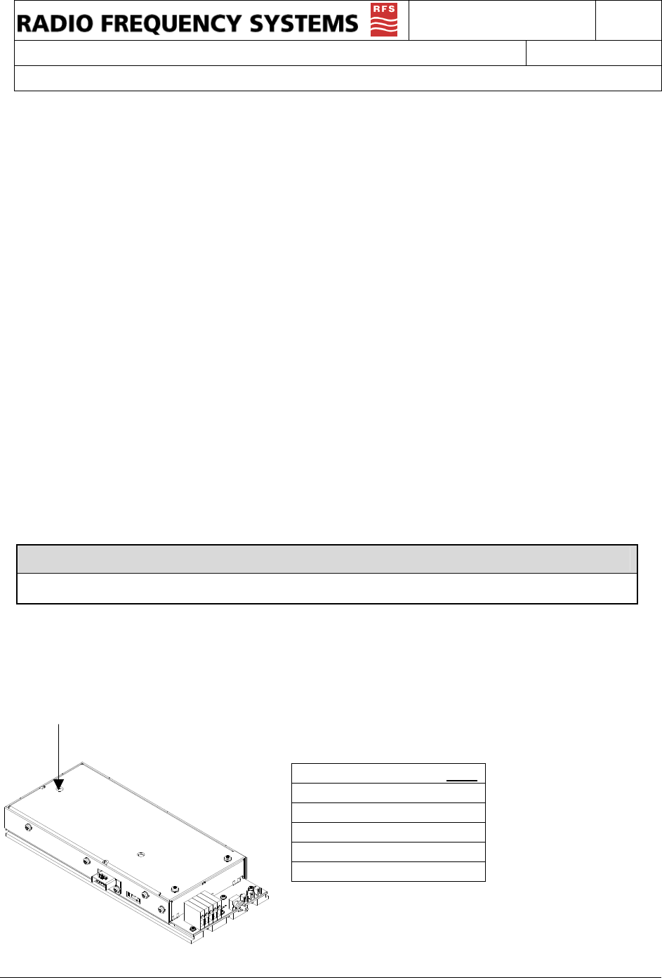
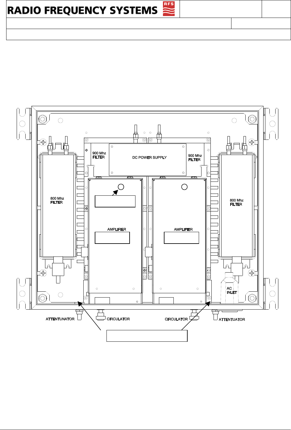
Component Location
Only the power supply is field replaceable part number 31500012900
AGC Adjust
Downlink
Uplink
Location of locking spacer

ITEM # 602100023500
DOCUMENT TYPE:
Operation and Installation Manual
REV: A
DOC #:
602100023
PAGE 16 OF 16
TITLE:
Bi-Directional Amplifier System
Maintenance, Repair and Warranty
Periodic Maintenance
No periodic maintenance is required for the 48960. As long as the units are kept away from extreme
temperatures and moisture, they should provide long-term, carefree operation.
However, periodically check all RF connections for corrosion, strain damage, and proper tightness.
Also, periodically check the AC power connections for integrity.
Ordering and Returning Components
For technical assistance, call Radio Frequency Systems Applications Engineering at 1-800-659-
1880.
For returns, repairs, and ordering, contact Radio Frequency Systems Customer Service at 1-800-
321-4700 for a Return Authorization Number. Be prepared to provide the model number, serial
number of the unit, as well as a description of the symptoms of the problem. Send components or
units freight pre-paid with the Return Authorization Number on the outside of the package to:
Radio Frequency Systems
175 Corporate Court
Meriden, CT 06450
Limited Warranty
The Seller warrants that, at the time of shipment, the products manufactured by the Seller are free
from defects in material and workmanship. The Seller's obligation under this warranty is limited to
replacement or repair of such products within one year from the date of shipment. No material is
accepted for replacement or repair without written authority of the Seller. Replacement or repair is
made only after an examination at the Seller's facility shows defective material or workmanship at the
time of manufacture. All shipping charges on the returned material must be prepaid by the Buyer.
The seller is in no event liable for consequential damages, installation costs or other costs of any
nature as a result of the use of the products manufactured by the Seller, whether used in accordance
with instructions or not. The Seller is not liable for replacement of any product damaged by lightning.
This warranty is in lieu of all others, either expressed or implied. No representative is
authorized to assume for the Seller any other liability in connection with the Seller's products.