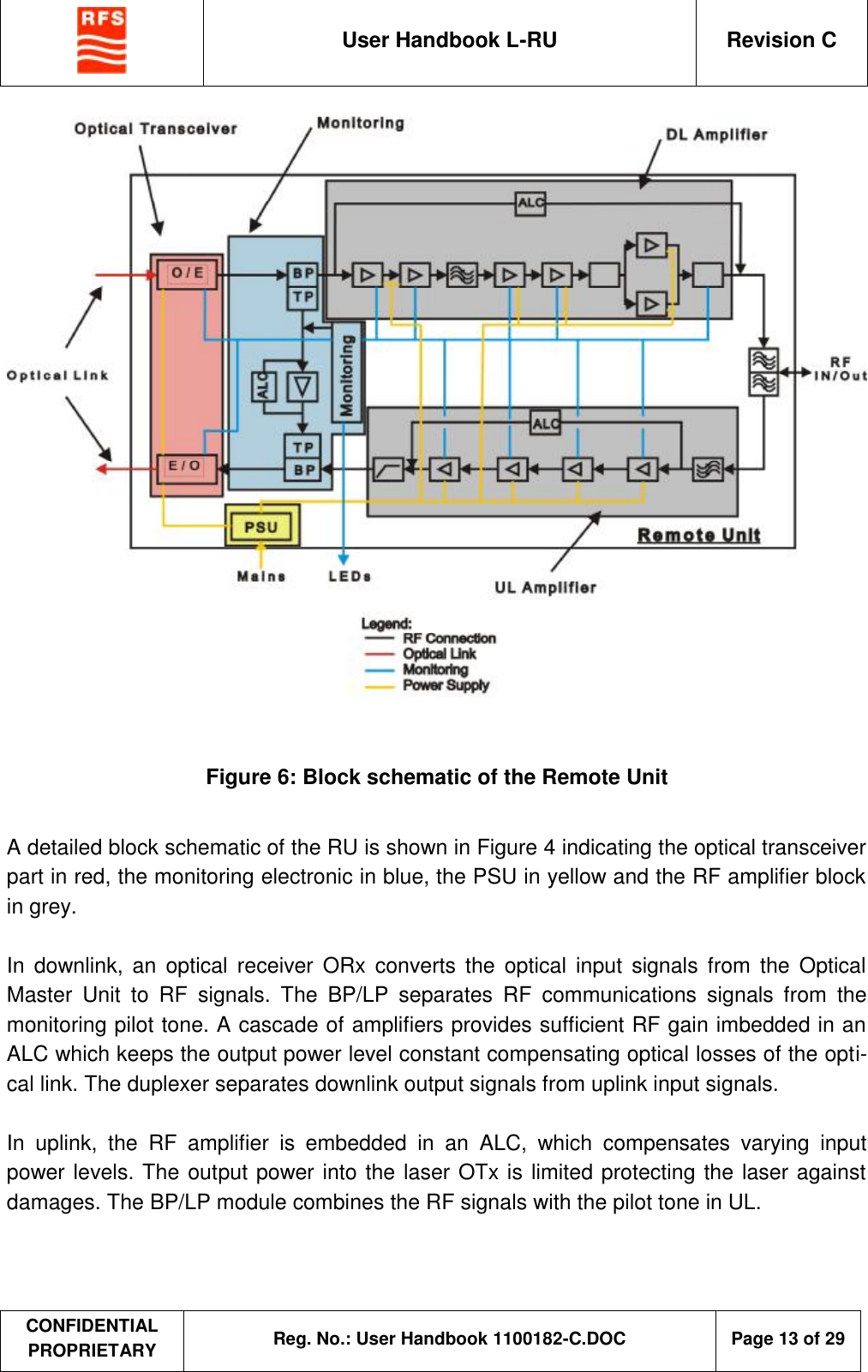
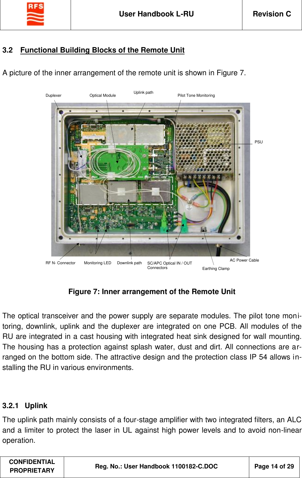
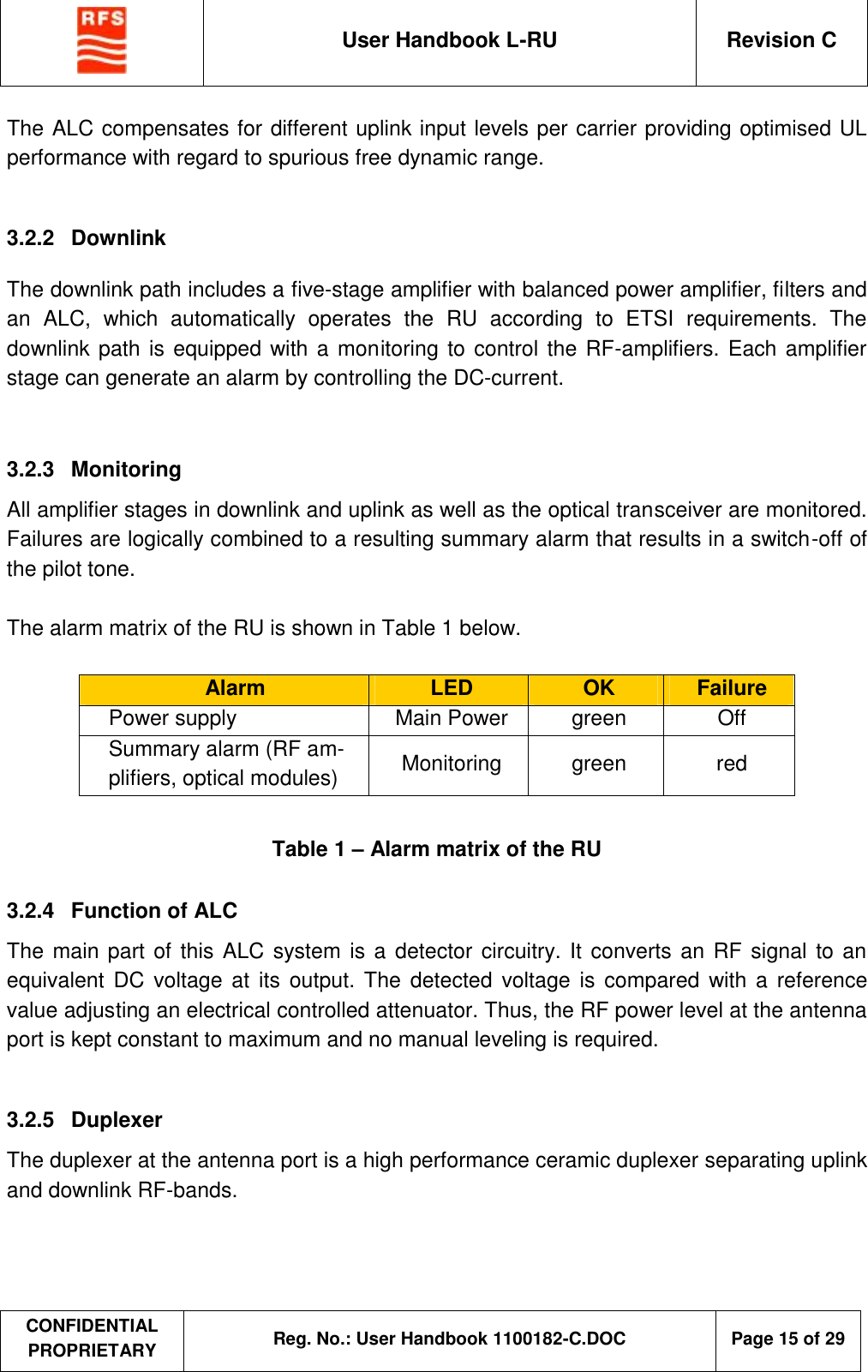
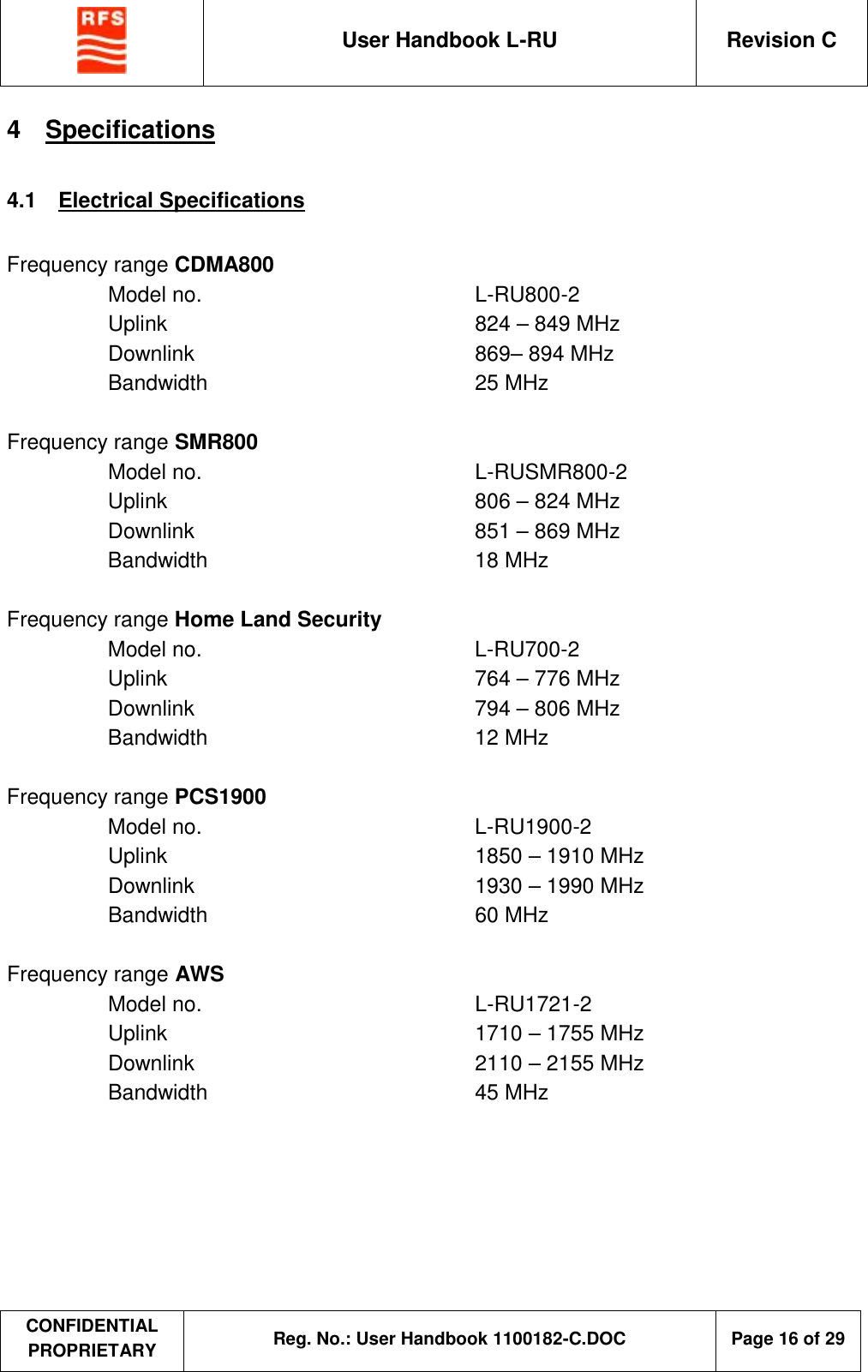
Radio Frequency Systems W1000176 Fiber Fed Remote Unit User Manual

Radio Frequency Systems Inc Fiber Fed Remote Unit

User Manual

 User Handbook L-RU  Revision C  CONFIDENTIAL PROPRIETARY Reg. No.: User Handbook 1100182-C.DOC   Page 1 of 29    ClearFill®Space1   L-RU  (incl. L-RU800-2, L-RUSMR800-2, L-RU700-2, L-RU1900-2, L-RU1721-2)    User Handbook    Part. No.:  L-RU800-2:  16501014 L-RUSMR800-2:  16501015 L-RU700-2:  16501016 L-RU1900-2:  16501017 L-RU1721-2:  16501018      Radio Frequency Systems GmbH Kabelkamp 20 D-30179 Hanover (Germany) Tel.: +49 511 676 2731 Fax: +49 511 676 3750
 User Handbook L-RU  Revision C  CONFIDENTIAL PROPRIETARY Reg. No.: User Handbook 1100182-C.DOC   Page 2 of 29  Contents  1 GENERAL  4 1.1 IMPRINT  4 1.2 ABBREVIATIONS  5 2 DESCRIPTION OF CLEARFILL®SPACE1 SYSTEM  6 2.1 GENERAL SYSTEM PERFORMANCE  9 3 DESCRIPTION OF REMOTE UNIT  11 3.1 BLOCK SCHEMATICS OF THE REMOTE UNIT 12 3.2 FUNCTIONAL BUILDING BLOCKS OF THE REMOTE UNIT  14 3.2.1 Uplink  14 3.2.2 Downlink  15 3.2.3 Monitoring  15 3.2.4 Function of ALC  15 3.2.5 Duplexer  15 4 SPECIFICATIONS  16 4.1 ELECTRICAL SPECIFICATIONS  16 4.2 MECHANICAL SPECIFICATIONS  18 4.3 OPTICAL LINK  18 4.4 COMPLIANCE  18 5 MODULE DESCRIPTIONS AND SPECIFICATIONS  19 5.1 OPTICAL TRANSCEIVER  19 5.1.1 Optical Transmitter  19 5.1.2 Optical Receiver  19 5.2 POWER SUPPLY  19 6 INSTALLATION AND COMMISSIONING  20 6.1 GENERAL STATEMENTS  20 6.1.1 Safety Considerations / Sicherheitshinweise (English / Deutsch)  20 6.1.2 Packing List  20 6.2 INSTALLATION PROCEDURE  21
 User Handbook L-RU  Revision C  CONFIDENTIAL PROPRIETARY Reg. No.: User Handbook 1100182-C.DOC   Page 3 of 29  6.3 COMMISSIONING PROCEDURE  23 7 MAINTENANCE, REPAIR AND WARRANTY  24 7.1 INTRODUCTION  24 7.2 ROUTINE CHECKS  24 7.3 REPAIR  24 7.4 TROUBLESHOOTING 25 7.5 WARRANTY  28 8 NOTES  29
 User Handbook L-RU  Revision C  CONFIDENTIAL PROPRIETARY Reg. No.: User Handbook 1100182-C.DOC   Page 4 of 29  1  General  Thank you for selecting this RFS product. We are confident that you will find this product in proper working order and meeting all stated specifications.  Please read this manual. A full understanding of product operation will support optimal per-formance and prevent accidental damage not covered by the stated warranty.  1.1   Imprint  These operating instructions are published by           No reproduction (including translation) is permitted in whole or part e.g. photocopy, micro-filming or storage in electronic data processing equipment, without the express written consent of the publisher. The operating instructions reflect the current technical specifica-tions at time of print. We reserve the right to change the technical or physical specifica-tions.  Radio Frequency Systems GmbH Kabelkamp 20 D-30179 Hanover (Germany) Tel.: +49 511 676 2731 Fax: +49 511 676 3750
 User Handbook L-RU  Revision C  CONFIDENTIAL PROPRIETARY Reg. No.: User Handbook 1100182-C.DOC   Page 5 of 29     1.2  Abbreviations  ALC  Automatic Level Control BP  Band-pass BTS  Base Transceiver Station DAS  Distributed antenna system DL  Downlink EIN  Equivalent Input Noise EMI  Electro Magnetic Interference EN  A standard established by the European Committee for Standardization ETSI  European Telecommunications Standards Institute HP  High-pass HU  Height Units IEC  International Electrotechnical Commission - International standards organization dealing with electrical, electronic and related technologies IP3  Third-order intercept point MU  Master Unit ORx  Optical receiver OTRx  Optical transceiver OTx  Optical transmitter PCB  Printed Circuit Board POI  Point of interception PSU  Power supply unit PTFE  Polytetrafluoroethylene RoHS  Restriction of Hazardous Substances RU  Remote Unit TRx  Transceiver (Transmitter-Receiver) UL  Uplink WEEE  Waste of Electrical and Electronical Equipment WiFi  Wireless Fidelity
 User Handbook L-RU  Revision C  CONFIDENTIAL PROPRIETARY Reg. No.: User Handbook 1100182-C.DOC   Page 6 of 29  2  Description of ClearFill®Space1 System When coverage is needed in a large building (typically larger than 200.000 sq ft), RF re-peaters driving passive distributed antenna systems (DAS) often become impractical due to their coaxial cable loss. ClearFill®Space1 is offering great value because the signal loss in fiber is extremely low compared to coaxial cable. ClearFill®Space1 can provide excellent coverage over broad areas.  ClearFill®Space1 is a mid power indoor coverage solution that meets any RF distribution needs – from simple entry-level systems to the most complex applications.   ClearFill®Space1 is a modular RF-over-fiber distribution system that provides reliable and highest quality indoor coverage of 2G and 3G wireless services in airports, hospitals, cam-pus, enterprises, convention centers, high-rise buildings and tunnels.   The ClearFill®Space1 system is a plug-and-play fiber-optical repeater system consisting of two main components: a Master Unit (MU) and Remote Units (RU), connected via a fiber-optical link(s).   L-MU series Master Unit L-MU1 drives one remote unit (band selective) L-MU2 drives two remote units (band selective) L-MU4 drives four remote units (band selective)   Figure 1 – Master unit L-MU of ClearFill®Space1  Three types of RF broadband MU are feeding one, two or four RU providing high level of flexibility.  This handbook refers to the RU of a ClearFill®Space1 system. For further information about the L-MU please refer to the User handbook L-MU.
 User Handbook L-RU  Revision C  CONFIDENTIAL PROPRIETARY Reg. No.: User Handbook 1100182-C.DOC   Page 7 of 29   The RU is a fiber-fed, band-selective single-band RF amplifier. The automatically leveled composite output power (22dBm, equivalent to 2x19dBm for two RF carriers) of a single RU guarantees best coverage at low prices and is able to drive an area of typically 50.000 sq ft.  L-RU800-2 L-RUSMR800-2 L-RU700-2 L-RU1900-2 L-RU1721-2 for 50.000 sq ft for 50.000 sq ft for 50.000 sq ft for 50.000 sq ft for 50.000 sq ft L-RU series Fiber Fed Remote Unit  Figure 2 – Remote unit L-RU of ClearFill®Space1
 User Handbook L-RU  Revision C  CONFIDENTIAL PROPRIETARY Reg. No.: User Handbook 1100182-C.DOC   Page 8 of 29   An example for a system topology is presented in Figure 3.   Figure 3 – Example of ClearFill®Space1 System Topology  Both devices (L-MU and L-RU) include an automatic level control (ALC) in uplink and downlink that eliminates system gain variation, regardless of optical loss guarantying opti-mised system performance under minimised installation effort.  The interface to the BTS / Node B or an Off-Air Repeater is the master unit. In case of a multi-operator system a combining network (POI) has to be used in order to adapt the in-put signal to the MU interface.  An opportunity to extend the system to distribute WiFi over the same DAS is foreseen via RFS WiFi injection port.  L-RU L-RU
 User Handbook L-RU  Revision C  CONFIDENTIAL PROPRIETARY Reg. No.: User Handbook 1100182-C.DOC   Page 9 of 29  2.1  General System Performance  Optical link:  •  0 to 6 dB optical attenuation •  Mono-mode fiber  Plug-and-play function:  •  Self-leveling system in UL and DL •  Fixed output power levels of RU in DL •  Fixed output power levels of RU in UL for laser protection •  ALC of MU in DL for auto-leveling of composite input power for varying num-ber of carriers •  ALC of MU in UL for auto-leveling of parallel optical links and compensating for various optical link losses •  Commissioning effort reduced to a minimum •  Operating under ETSI requirements    Application:  •  RU and MU build up an end-to-end RF system connected via a pair of optical fiber. See User Handbook of Master Unit (L-MU series) for additional information about MU. • The system MU-RU and its plug-and-play functionality  is designed to operate for typical DAS applications with nominal UL input signal strengths (into RU RF in/out port) in the range of -55 dBm to -35 dBm.  •  As every  distributed  RF-over-fiber system, ClearFill Space1 introduces signal de-lays in DL and in UL due to the use of single-mode optical fibers between MU and RU. This delay has to be taken into account by cellular network planning/operation for appropriate setting of BTS/NodeB search windows. This also applies for remote BTS/NodeB’s  which may be  connected to a  ClearFill Space1 system over-the-air using an off-air repeater with donor antenna.  Establishing a connection  between mobile  / handheld device and BTS/NodeB may  fail due to of improper setting of search window / range.
 User Handbook L-RU  Revision C  CONFIDENTIAL PROPRIETARY Reg. No.: User Handbook 1100182-C.DOC   Page 10 of 29  Monitoring:  Managing the system in case of malfunction is very simple. Two alarm LED easily refer to specific malfunction for the optical link connection and/or for the power supply. Correction of an identified malfunction is done by exchange of faulty unit. Thus makes Clear-Fill®Space1 a very service-friendly system.  LED specification and connectivity (Two type of alarm LED at RU):  •  Green illuminated “Main power” LED indicates that the power is ON. •  Green illuminated “Monitoring” LED indicates that the received optical laser signal from MU is functioning within spec.
 User Handbook L-RU  Revision C  CONFIDENTIAL PROPRIETARY Reg. No.: User Handbook 1100182-C.DOC   Page 11 of 29  3  Description of Remote Unit  The medium-power RU is designed for applications in buildings and tunnels. Operating in ALC modus in uplink and downlink the RU provides an easy plug-and-play handling with-out system leveling. The output power level in downlink is fixed according to ETSI re-quirements. The monitoring of function is locally indicated by LEDs. The summary alarm switches the pilot tone to the optical Master Unit. The optical transceiver operates on mono-mode fibers.  The remote unit comprises an optical transmitter and receiver, active and passive RF components, and a single RF input / output port.     RF IN / OUT Connector LED Monitoring AC Power Cable (not shown) Earthing Clamp DL Optic in SC/APC connector UL Optic out SC/APC connector LED Mains  Figure 4: Picture of Optical Remote Unit
 User Handbook L-RU  Revision C  CONFIDENTIAL PROPRIETARY Reg. No.: User Handbook 1100182-C.DOC   Page 12 of 29  3.1  Block Schematics of the Remote Unit  Figure 5 shows the functional block schematic of the remote unit, which basically identifies the main building blocks and their interactions. All external interfaces are clearly identified as arrows crossing the boundary of the remote unit.   E / O PSU Active RF Monitoring DL Optical Input RF  Input / Output Status LEDs Power Supply Legend:,     RF Connection     Optical Link   Pilot Tone   Monitoring Control   Module Power Supply  UL Optical Output   Figure 5: Functional Block Schematic of the Remote Unit  •  PSU: internal power supply for RU •  E/O: Optical transmitter and receiver integrated into one transceiver module •  Active RF: The combination of all passive and active modules for uplink and downlink including supporting electronics •  Monitoring: All electronics for alarming.  The Remote Unit consists of the following functional building blocks • The optical transceiver  • The pilot tone monitoring • The downlink path • The uplink path •  Duplexer •  Power supply
 User Handbook L-RU  Revision C  CONFIDENTIAL PROPRIETARY Reg. No.: User Handbook 1100182-C.DOC   Page 13 of 29    Figure 6: Block schematic of the Remote Unit  A detailed block schematic of the RU is shown in Figure 4 indicating the optical transceiver part in red, the monitoring electronic in blue, the PSU in yellow and the RF amplifier block in grey.  In downlink, an optical receiver ORx converts the optical input signals from the Optical Master Unit to RF signals. The BP/LP separates RF communications signals from the monitoring pilot tone. A cascade of amplifiers provides sufficient RF gain imbedded in an ALC which keeps the output power level constant compensating optical losses of the opti-cal link. The duplexer separates downlink output signals from uplink input signals.  In uplink, the RF amplifier is embedded in an ALC, which compensates varying input power levels. The output power into the laser OTx is limited protecting the laser against damages. The BP/LP module combines the RF signals with the pilot tone in UL.
 User Handbook L-RU  Revision C  CONFIDENTIAL PROPRIETARY Reg. No.: User Handbook 1100182-C.DOC   Page 14 of 29  3.2  Functional Building Blocks of the Remote Unit  A picture of the inner arrangement of the remote unit is shown in Figure 7.        AC Power Cable SC/APC Optical IN / OUT Connectors RF N- Connector PSU Monitoring LED Downlink path Earthing Clamp Uplink path  Pilot Tone Monitoring Optical Module Duplexer  Figure 7: Inner arrangement of the Remote Unit  The optical transceiver and the power supply are separate modules. The pilot tone moni-toring, downlink, uplink and the duplexer are integrated on one PCB. All modules of the RU are integrated in a cast housing with integrated heat sink designed for wall mounting. The housing has a protection against splash water, dust and dirt. All connections are ar-ranged on the bottom side. The attractive design and the protection class IP 54 allows in-stalling the RU in various environments.   3.2.1  Uplink The uplink path mainly consists of a four-stage amplifier with two integrated filters, an ALC and a limiter to protect the laser in UL against high power levels and to avoid non-linear operation.
 User Handbook L-RU  Revision C  CONFIDENTIAL PROPRIETARY Reg. No.: User Handbook 1100182-C.DOC   Page 15 of 29  The ALC compensates for different uplink input levels per carrier providing optimised UL performance with regard to spurious free dynamic range.  3.2.2  Downlink The downlink path includes a five-stage amplifier with balanced power amplifier, filters and an ALC, which automatically operates the RU according to ETSI requirements. The downlink path is equipped with a monitoring to control the RF-amplifiers. Each amplifier stage can generate an alarm by controlling the DC-current.   3.2.3  Monitoring All amplifier stages in downlink and uplink as well as the optical transceiver are monitored. Failures are logically combined to a resulting summary alarm that results in a switch-off of the pilot tone.  The alarm matrix of the RU is shown in Table 1 below.  Alarm  LED  OK  Failure Power supply  Main Power  green  Off Summary alarm (RF am-plifiers, optical modules)  Monitoring  green  red  Table 1 – Alarm matrix of the RU 3.2.4  Function of ALC  The main part of this ALC system is a detector circuitry. It converts an RF signal to an equivalent DC voltage at its output. The detected voltage is compared with a reference value adjusting an electrical controlled attenuator. Thus, the RF power level at the antenna port is kept constant to maximum and no manual leveling is required.  3.2.5  Duplexer The duplexer at the antenna port is a high performance ceramic duplexer separating uplink and downlink RF-bands.
 User Handbook L-RU  Revision C  CONFIDENTIAL PROPRIETARY Reg. No.: User Handbook 1100182-C.DOC   Page 16 of 29  4  Specifications 4.1  Electrical Specifications  Frequency range CDMA800   Model no.    L-RU800-2   Uplink    824 – 849 MHz   Downlink    869– 894 MHz   Bandwidth    25 MHz      Frequency range SMR800   Model no.    L-RUSMR800-2   Uplink    806 – 824 MHz   Downlink    851 – 869 MHz   Bandwidth    18 MHz  Frequency range Home Land Security   Model no.    L-RU700-2   Uplink    764 – 776 MHz   Downlink    794 – 806 MHz   Bandwidth    12 MHz  Frequency range PCS1900   Model no.    L-RU1900-2   Uplink    1850 – 1910 MHz   Downlink    1930 – 1990 MHz   Bandwidth    60 MHz  Frequency range AWS   Model no.    L-RU1721-2   Uplink    1710 – 1755 MHz   Downlink    2110 – 2155 MHz   Bandwidth    45 MHz
 User Handbook L-RU  Revision C  CONFIDENTIAL PROPRIETARY Reg. No.: User Handbook 1100182-C.DOC   Page 17 of 29  Composite Output Power in DL    22 dBm typical  RF impedance    50 Ω Return loss    > 10 dB typical  Input voltage     AC 115/230 V  ±10%, 50/60 Hz  ±5%, autoranging     Gland with 1.5m cables Power consumption  < 30 W   ALC operation (UL window at RF in/out port)  ALC active:  - 55dBm to -35 dBm *)         *) target window for plug-and-play mode       Linear mode: < -55 dBm   Master Unit    see User Handbook L-MU series
 User Handbook L-RU  Revision C  CONFIDENTIAL PROPRIETARY Reg. No.: User Handbook 1100182-C.DOC   Page 18 of 29  4.2  Mechanical Specifications Size      height: 240 mm       width: 320 mm       depth: 70 mm Colour      black (RAL 9005)       scratch resistant Cooling:      convection cooling, without fans Weight:      approx. 5,8 kg Operating Temperature Range    -10°C  to + 50°C Storage Temperature Range    -20°C  to + 75°C Relative humidity     0% to 90%        (non-condensing) RF Connectors:    N type female Earthing:      M8 bolt Location of the interfaces and control element  on bottom when wall mounted Environmental Protection:     IP 54   4.3  Optical Link  Fiber optic type  mono-mode, 9 / 125 Number of fibers  2 (one for UL, one for DL) Optical connectors  SC / APC Wavelength  1310 nm Optical attenuation  max. 5 km (3miles) distance  or 6 dB optical attenuation  4.4  Compliance  EMC    ETSI EN 301 489-1 FCC    FCC part 15/ 22/ 24/ 27/ 90 Safety     IEC / EN60950 Optic    Laser Diode according to IEC / EN 60 825 – 1, class 1     Fiber Optic Link according to IEC / EN 60 825 – 2
 User Handbook L-RU  Revision C  CONFIDENTIAL PROPRIETARY Reg. No.: User Handbook 1100182-C.DOC   Page 19 of 29  5  Module Descriptions and Specifications 5.1  Optical Transceiver 5.1.1  Optical Transmitter Wavelength  1310 nm, single mode Optical Output Power  3 dBm typical Modulation gain  0,08 mW/mA   5.1.2  Optical Receiver Wavelength  1310 nm, single mode Maximum input power  3 dBm optical   5.2  Power Supply  The in-built PSU is a high reliability, wide input range, and high efficient AC-DC converter with four outputs at 5 V, 12 V, -12 V and 24 V. To reduce the outgoing disturbance an EMI-filter is built in. To reduce the inrush current at start-up, a soft start circuit is implemented. The output is short circuit, overload and over voltage protected.
 User Handbook L-RU  Revision C  CONFIDENTIAL PROPRIETARY Reg. No.: User Handbook 1100182-C.DOC   Page 20 of 29  6  Installation and Commissioning 6.1  General Statements 6.1.1  Safety Considerations / Sicherheitshinweise (English / Deutsch)  Safety Considerations PTFE and PTFE Composite Materials Materials should never be heated to the point where smoke or fumes are evolved. Any person feeling drowsy after coming into contact with PTFE especially dust or fumes should seek medical attention.  Sicherheitshinweise PTFE und PTFE Verbundwerkstoffe PTFE und PTFE Verbundwerkstoffe dürfen nicht derart erhitzt werden, dass es zu Rauchentwicklung kommt. Personen die mit solchem Rauch in Berührung kommen und sich unwohl fühlen (z.B. Schläfrigkeit), sollten dringend medizinische Beratung in Anspruch nehmen.  6.1.2  Packing List Additionally to the remote unit following parts are enclosed to the delivery set:  §  User Handbook L-RU § Test report L-RU §  Packing list §  4 screws, 4 washers, 4 dowels
 User Handbook L-RU  Revision C  CONFIDENTIAL PROPRIETARY Reg. No.: User Handbook 1100182-C.DOC   Page 21 of 29  6.2  Installation Procedure The installation may only be carried out by qualified personnel that is familiar with the haz-ards involved and the relevant statutory regulations. Before begin of the installation of the RU, all RF cable and optical cable should be installed first. The procedure for installing the L-RU is generally as follows:  1.  Transport the RU to the chosen site in its packaging. 2.  Remove the RU from its packaging and check that there are no obvious signs of physical damage. If the unit is physically damaged do not proceed with the in-stallation. 3.  Drill or fit four wall fixings to which the RU is to be fitted. For the physical dimen-sions of the wall fixings refer to Figure 8. The type of fixings will depend on the construction of the wall. It has to be ensured that the wall fixings are adequate for a total weight of more than 6 kg.  Note: The provided dowels in the accessories are suitable for installation in indoor areas (closed spaces) only and for following wall constructions.  • Concrete  • Pre-stressed hollow-core concrete slabs  • Natural stone with dense structure  • Solid brick  • Sand-lime solid brick  • Solid block made from lightweight concrete  • Aircrete  • Solid panel made from gypsum  • Hollow block made from lightweight concrete  • Slabs made of perforated bricks  • Hollow concrete blocks etc.  For the installation in other environment (e. g. tunnel) or other wall construction an-other dowel must be used, which is suitable for this environment and wall construc-tion.  4.  Fit and secure the RU on to the fixings. It is strongly recommended that all four fixing points be used.  5.  Earth the RU in accordance with international and local recommendations and requirements. 6.  Connect the RU to RF distributing DAS or radiating cable. Connect the two opti-cal link cables from and to the assigned MU and plug in the power cable.
 User Handbook L-RU  Revision C  CONFIDENTIAL PROPRIETARY Reg. No.: User Handbook 1100182-C.DOC   Page 22 of 29  7.  Ensure that all the cables leaving the RU first travel downward to ensure that any moisture is directed away from the RU. This is important for installation in tunnel environment.    Note:  It is important that the above installation instructions are followed in the sequence presented to ensure a correct and save installation.   Ensure a suitable mains power  supply is available adjacent to the RU. Connect the RU main cables to the mains supply in accordance with local wiring.   Note:   Avoid looking directly into the optical connectors of the RU if no op-tical cables or protective sleeve are installed and the RU is switched on.      213 mm 301 mm  Figure 9: Drill Template for wall installation
 User Handbook L-RU  Revision C  CONFIDENTIAL PROPRIETARY Reg. No.: User Handbook 1100182-C.DOC   Page 23 of 29  6.3  Commissioning Procedure  The ClearFill®Space1 system (consisting of MU and RU) is equipped with a combination of ALCs, minimum one at the input and one at the output. The dynamic range of the individ-ual ALCs and their reaction time is adjusted to each other. At least the whole system oper-ates in a balanced way providing defined power levels at the output of the system within the specified power levels at the system inputs.  Due to the self-levelling functionality no commissioning and testing of the ClearFill®Space1 system is necessary. The system can be set into operation as plug & play compensating automatically for fiber optical losses, for changes of number of operating RF carriers and for all types of temperature and aging effects.
 User Handbook L-RU  Revision C  CONFIDENTIAL PROPRIETARY Reg. No.: User Handbook 1100182-C.DOC   Page 24 of 29  7  Maintenance, Repair and Warranty 7.1  Introduction  The RU is designed and built to require no periodic maintenance. As long as the unit is kept away from extreme temperatures and moisture, it should provide long-term, carefree operation. It is strongly recommended that no invasive procedures are performed on the unit in an attempt to verify performance. See section  7.2 for recommended routine performance variation checks.  7.2  Routine Checks  Although the RU is a low-maintenance unit, it is recommended to routinely verify the per-formance of the RU by making test calls or detailed system checks on the actual radio coverage. Several test calls should be made at different positions within each area to get an overall picture of the system performance. This is by far the best way to check the sys-tem as it tests the whole system from an operational viewpoint as seen by the users.  It is strongly recommended that no invasive procedures be performed on the unit in an attempt to verify performance unless a serious problem with performance has been identi-fied as described above. Any such invasive procedures are more likely to do damage to the system and create intermittent performance than to be of any practical value.  7.3  Repair   Repairs may only be carried out by qualified personnel that are familiar with both the haz-ards involved and the relevant statutory regulations. Unauthorized modifications or repairs invalidate the warranty claim. Before contact RFS customer service for repair request please prove the checklist in sec-tion 7.4 (Troubleshooting).   For returns, repairs and ordering contact your RFS customer service or technical.consulting@rfsworld.com.
 User Handbook L-RU  Revision C  CONFIDENTIAL PROPRIETARY Reg. No.: User Handbook 1100182-C.DOC   Page 25 of 29  7.4  Troubleshooting  You have obtained a state-of-the-art product, which is reliable and operationally safe. Nevertheless, problems or malfunctions may occur. Following we will present strategies how to eliminate possible problems. The safety instructions must be observed (see notes below the table)! Pease follow the procedures for the troubleshooting in the prescribed order.  Checklist RU  Symptoms  Reason  Procedure •  All RU LED are off. The power supply is inac-tive. 1. Check the AC voltage 2. Check the connectors of AC cable 3. Check the AC power cable for damages The outputs of the PSU have over or under volt-age Reset the RU by switching Off and after a few seconds On of the AC power •  RU PSU LED is red. PSU is defect  Please contact RFS customer ser-vice for repair or replacement of RU •  RU Monitoring LED is red. Problem with optical sig-nal Please check the system trouble-shooting list (see next page).   Note:  Always remove AC power cable before checking or changing fuses.  115 / 230 VAC can be lethal.  Note: To avoid shock, injury or damage to the RU: use only fuses with  the amperage, interrupt, voltage and speed ratings specified.   Note:  Don’t open housing of RU. Warranty exclusion in case housing has been opened!
 User Handbook L-RU  Revision C  CONFIDENTIAL PROPRIETARY Reg. No.: User Handbook 1100182-C.DOC   Page 26 of 29  System Checklist  The safety instructions must be observed (see notes below the table)! The following troubleshooting refers to specific alarm LED indications on MU and RU in a ClearFill®Space1 system environment. Please follow the procedures for the troubleshoot-ing in the prescribed order. For guidance the column “Symptoms” gives  specific LED status information combinations at MU and RU.  Symptoms  Reason  Procedure •  MU Summary OTx LED is red One or more optical transmitter is inactive  Please contact RFS customer ser-vice for repair or replacement of RU •  MU Link LED to RU is red  No optical signal 1. Check the optical connectors of the inactive link for fastening or damage 2. Check the optical cable between MU and RU for damage 3. Clean with special equipment the ferrules at the optical connectors 4. Check the following variety of troubleshooting, described below No optical signal in UL  1.  Check the optical connectors of the UL (on the MU and RU site) for fastening or damage 2.  Check the optical cable in UL for damage •  MU Link LED is red / RU Monitor-ing LED is green  OTx of MU is inactive (in this case summary OTx LED is red as well) 3.  Please contact RFS customer ser-vice for repair or replacement of MU
 User Handbook L-RU  Revision C  CONFIDENTIAL PROPRIETARY Reg. No.: User Handbook 1100182-C.DOC   Page 27 of 29   Symptoms  Reason  Procedure No optical signal 1.  Check the optical connectors of the UL and DL (on the MU and RU site) for fastening or damage 2.  Check the optical cable in UL and DL for damage 3.  Clean with special equipment the ferrules at the optical connectors OTRx of MU is inactive  4.  Connect the optical cables of the failure link to the other optical link connectors (in case of L-MU2 and L-MU4) or to the spare device if available (for L-MU1). If the link status OK, then contact RFS cus-tomer service for repair or re-placement of MU. Optical cable is inactive 5.  If the link status is on failure (see point 4) retry the communication with spare devices (MU and RU) if available.  6.  In case of failure status the optical cable is out of order.  •  MU Link LED is red / RU Monitor-ing LED is red MU or RU is inactive 7.  In case of OK status (see point 5) is MU or RU is inactive. The failure unit can be detected by sequential change of the only one unit (MU or RU). Please contact RFS cus-tomer service for repair or re-placement of this unit. •  No signal on data / monitoring inter-face  No data available 1.  Check the data connectors for fas-tening or damage 2.  Check the data cable for damage
 User Handbook L-RU  Revision C  CONFIDENTIAL PROPRIETARY Reg. No.: User Handbook 1100182-C.DOC   Page 28 of 29  7.5  Warranty  The Warranty time is 1 year beginning with the delivery of the equipment. Warranty ser-vices do not extend the warranty time. The warranty is not valid for the following:  •  Damage caused by improper use •  Damage caused by non-adherence to user handbook •  Devices which have been opened provided this is not described in the user handbook for maintenance purposes. •  Devices whose serial number labels have been changed, damaged, removed or exchanged. •  Devices whose warranty seals are changed, damaged, removed or broken.  We will correct any fault  free of charge or exchange item (excluding shipment), if  • It can be proved that they are manufacturing faults. • The faults are reported immediately. • The faults are reported within the warranty time
 User Handbook L-RU  Revision C  CONFIDENTIAL PROPRIETARY Reg. No.: User Handbook 1100182-C.DOC   Page 29 of 29  8  Notes

Navigation menu