Radio Frequency Systems WINS-3900003 PCS 1900 Off-air repeater User Manual
Radio Frequency Systems Inc PCS 1900 Off-air repeater
User Manual
Radio Frequency Systems
Kabelkamp 20
30179 Hannover, Germany
Tel.: +49 511 676 2731
Fax: +49 511 676 2515
E-mail: sales.europe@rfsworld.com
1800MHz - 1900MHz ADJUSTABLE BANDWIDTH
OFF-AIR REPEATERS
OR1-SBHP1-1800
OR2-SBHP1-1800
OR1-SBHP1-1900
OR2-SBHP1-1900
TECHNICAL HANDBOOK
Doc. code 91 080 0701F - Rel. 04

1800MHz – 1900MHZ Off-Air Repeaters (OR Series) Page 91 080 0701F – Rel.04
INDEX 1
INDEX
1) SAFETY RULES ................................................................................................................................... 1
2) STANDARDS........................................................................................................................................ 2
2.1) MANUFACTURE LABELS
2.2) SYMBOLS
3) GENERAL DESCRIPTION ................................................................................................................... 3
3.1) EXAMPLE: USE IN TUNNELS
3.2) OPERATING PRINCIPLE - 1800MHz - 1900MHz ADJUSTABLE BAND OFF-AIR REPEATERS
3.3) ATTACHED DOCUMENTS
4) INSTALLATION AND POWER-UP PROCEDURES............................................................................ 4
4.1) INSTALLATION
A - INITIAL CHECK
B - POSITIONING THE REPEATER
C - POWER SUPPLY SOURCE CONNECTIONS AND ALARMS CONNECTIONS
D.C. POWERED EQUIPMENT
AC POWERED EQUIPMENT (ALTERNATE CURRENT)
4.2) POWER-UP
4.3) ROUTINE MAINTENANCE

1

1) SAFETY RULES
1.1 Introduction
The equipment described in this technical handbook has been designed and tested in conformity of
international safety standards IEC215 / EN60215 and IEC950 / EN60950; the equipment has to be used
under the responsibility of specialised personnel only. In accordance with IEC215 / EN60215, adjustment,
maintenance and repair of the exposed equipment shall be carried out only by qualified personnel, who are
aware of the hazards involved. The minimum qualifications are established in the standard.
Final installation of the systems must fulfil the EMF emission levels, as requested by regulations in force
(recommendation n. 1999/519/EC).
WARNING: Installation Notes
Modular equipment, intended to be housed insidea rack cabinet, must be installed within a protected
access area only.
This area must be opportunely protected by security system that will exclude the entry, even if accidental, to
not authorized and trained personnel. Alternatively, the cabinet, in which the equipment is housed, must be
closed on all sides, to allow the access to internal parts to authorized personnel only
When working on the equipment always make sure that the equipment is not connected to the mains
supply.
1.2 AC Power supply
Before power up always make sure that the equipment is connected to earth by using the equipment
grounding bolt.
If it is necessary to fit an AC power supply plug to power cable, the User must observe the following colour
codes: LIVE terminal to BROWN lead NEUTRAL terminal to BLUE lead EARTH terminal to GREEN/YELLOW
lead The User must also ensure that the protective earth wire would be the last to break, should the cable be
subject to excessive strain.
1.3 Safety precautions
For the correct and safe use of the equipment it is essential that both operation personnel and services
personnel follow generally accepted safety procedures (see IEC Publications 215: "Safety measures for
radio transmitting equipment" and 61010-1: "Safety requirements for electrical equipment for measurement,
control, and laboratory use") in addition to the safety precautions specified in this technical handbook.
Specific warnings and caution statements, where applicable, can be found throughout this technical
handbook. Warning and caution statements and/or symbols are marked on the equipment where is
necessary. (see also ANNEX n°1).
As far as the equipment safety devices are concerned please remind that: -periodic functional check shall be
carried out on protective devices; -functional check shall be carried out on protective devices, when they
have operated under fault conditions; -safety devices shall not be altered or disconnected except for
replacement; -safety circuit shall not be modified.
SAFETI RULES ENG

1.4 Caution and warning statements
Caution It's used to indicate the correct operation and maintenance, in order to prevent damage or
destruction of equipment or other property. Warning of danger Used to indicate the potential hazard that
requires correct procedures or practices in order to avoid personal injury.
1.5 Impaired safety protection
Whenever it is likely that safe operation is impaired, the apparatus must be in-operative and secured against
unintended operation. The appropriate servicing staff authority must be informed.
For instance, the safety is likely to be impaired if the equipment fails to perform the prescribed
measurements, or shows visible damages.
1.6 Electrostatic sensitive devices
In case of electrostatic sensitive devices ( for instance all ICs and many other semiconductor devices belong
to this class) it is essential to use a right protection to reduce the risk of personal injury. Careless handling,
during repair, may imply life danger. When repairing, make sure that you are connected with the same
potential as the ground of the equipment by means of the right devices, i.e. a GIRDLE (a wrist wrap with
resistance) and a WINDING CORD to be connected to the girdle and to the relevant socket placed on the
equipment.
You must also keep components and tools at this potential.
1.7 Electrolytic Capacitors
Non-solid electrolytic capacitors must not contain chemicals, which may be regarded as hazardous, if
incorrectly handled. Caution is necessary, should the outer case be fractured.
1.8 Electric shock
In case of electric shock it is recommended not to touch the person before breaking the circuit by means of
the power supply switch; should it be not possible to break the circuit power supply it would be advisable to
try to rescue the person by means of some insulating materials: e.g. a wood stick, a nylon cord or a suitable
service made of plastics, etc.
NEVER TOUCH ELECTROCUTED PEOPLE WITH YOUR HAND AS LONG AS THEIR BODIES ARE
SUBJECTED TO VOLTAGE, OTHERWISE YOU TOO WOULD GET ELECTOCUTED.
Call the doctor and then immediately perform the artificial respiration as described here below:
SAFETI RULES ENG

Lay the patient on his back with his arms parallel to his body; if the patient lies on an
inclined plane, please make sure that his stomach be slightly lower than his breast.
Open the patient's mouth and check if there are foreign bodies. Kneel down near the
patient at the same level as his head's, put one of your hands under his head and the
other one under his neck. Lift the patient's neck and let his head fall backwards the
most possible.
Shift your hand from the patient's neck to his chin; put your thumb between his chin
and his mouth, your forefinger along his jawbone, keep your other fingers tight. By
doing these operations start the self-oxygenation by means of deep breathings in
standing open-mouthed. With your thumb between the patient's chin and his mouth,
keep the patient's lips closed and blow into his nasal cavities.
During these operations see if the patient's breast rises. If it is not so, his nose may be
obstructed; in this case, by levering on his chin with your hand, open the patient's
mouth, put your lips on and blow into his oral cavity. Look at the patient's breast and
see if it rises. One can use this second method instead of the first one also if the
patient's nose is not obstructed, provided that his nose be occluded by squeezing his
nostrils with your hand after shifting it from his head. The patient's head must be kept
bent backwards the most possible.
Start with ten fast and deep expirations, then go on at the rhythm of twelve/fifteen expirations per minute.
Continue as long as the patient has recovered consciousness, or a doctor has ascertained his death.
1.9 Burns
As far as burns are concerned: Don't try to take off clothes from the burnt
parts; Pour some cold water on body burnt areas and ask immediately for a
doctor; Don't apply ointments or oily tinctures.
SAFETI RULES ENG
ANNEX 1
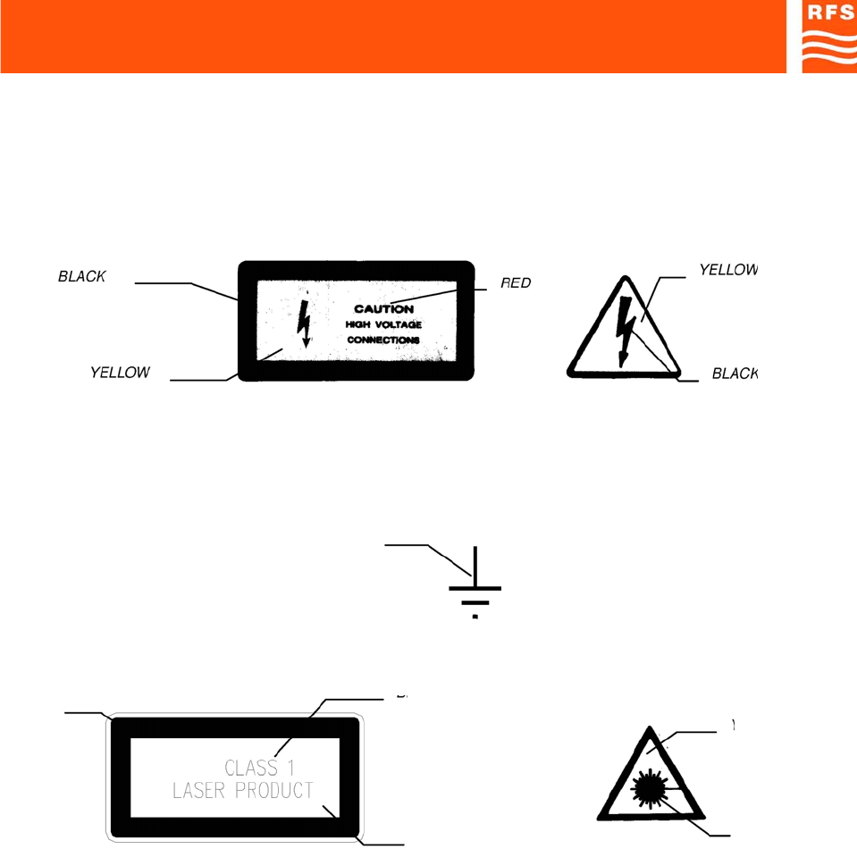
When the equipment or the modules are equipped with the labels as shown here below, it is essential to
observe the warnings contained
-LIVE VOLTAGE POINT
-PROTECTIVE EARTHING TERMINAL
BLACK
-CLASS 1 LASER PRODUCT
BLA
BLACK CK
YELLOW
YELLO
W
BLACK
EXPLANATORY LABEL (affixed to the WARNING LABEL (affixed to the CLASS 1 product side)
CLASS 1 product front)
Products which are of CLASS 1 as defined in the IEC EN 60825-1, fourth edition “Safety of laser
products -Part 1: Equipment classification, requirements and user's guide”. Even if the product is of
CLASS 1, please observe the following safety procedures, prescribed in the cited norm:
• do not observe directly the laser beam,
• do not use observation optics (lens, microscopes, telescopes, etc.),
• do not expose eyes directly.
SAFETI RULES ENG
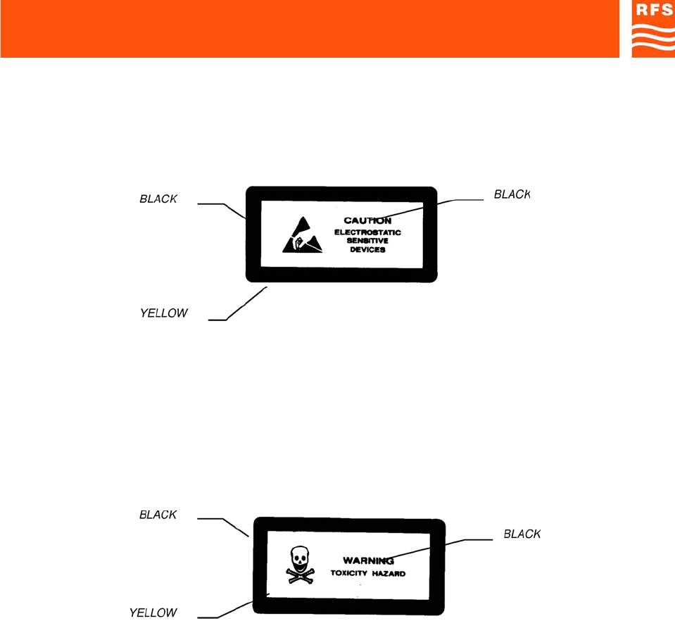
-DEVICES SENSITIVE TO THE ELECTROSTATICS
WARNING: Please observe the due precautions in handling devices which are sensitive to the
electrostatics.
-NON-SOLID ELECTROLYPTIC CAPACITORS MAY CONTAIN CHEMICALS TO BE REGARDED AS
HAZARDOUS, IF INCORRECTLY HANDLED.
WARNING
THE MAXIMUM CAUTION IS REQUIRED IF THE OUTER CASE IS FRACTURED
SAFETI RULES ENG

2

STANDARDS Page 1
2) STANDARDS
2.1. MANUFACTURE LABELS
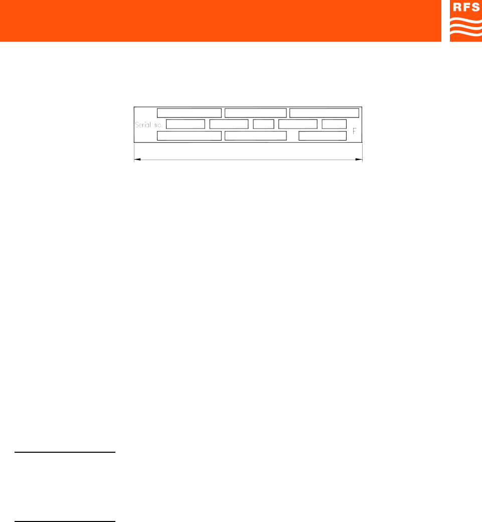
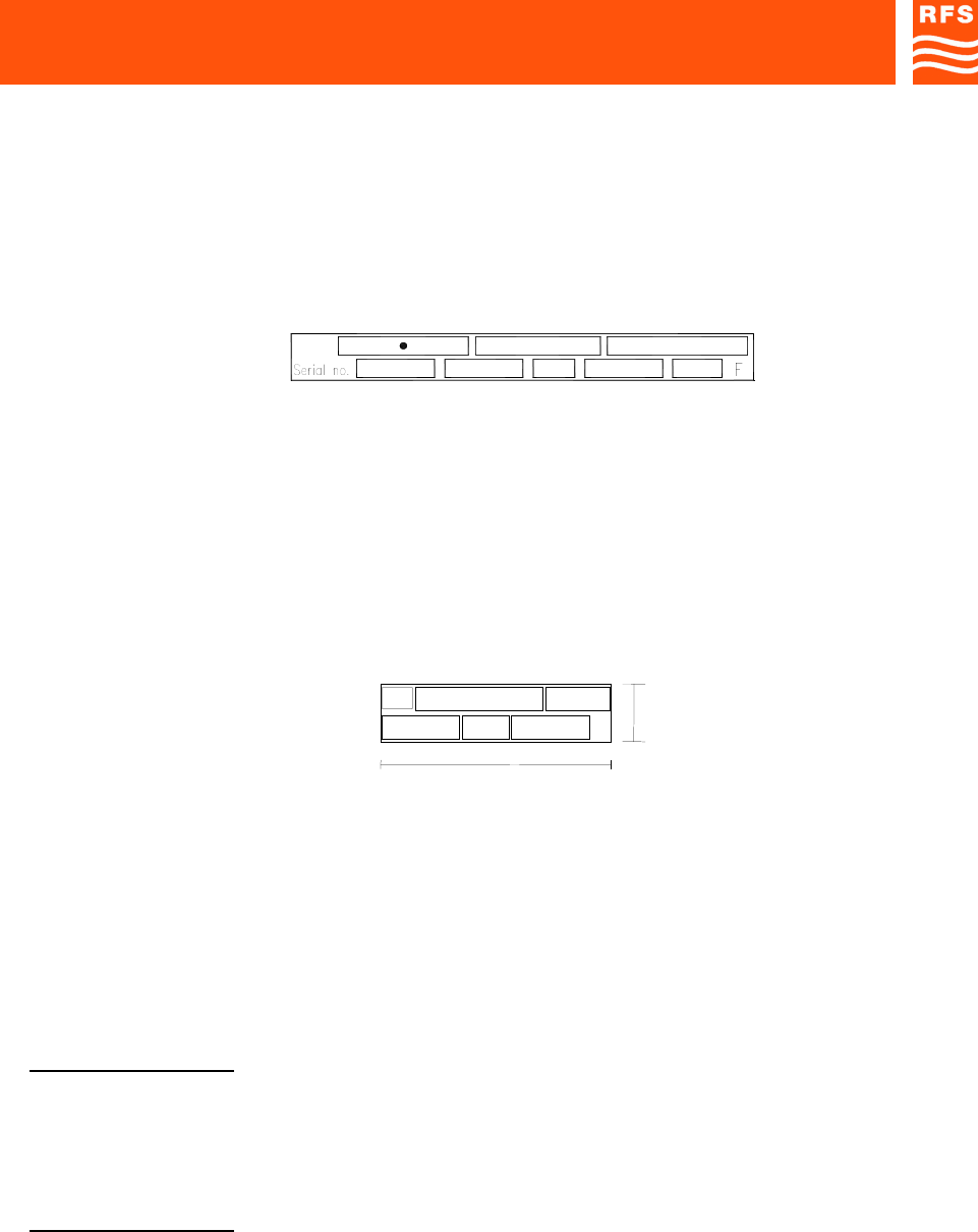
2.1.1 BAR CODE LABEL
Label fields (ref. Fig.1):
a) Serial number: this field contains the serial number (made up of a 7-digit sequential group) of the
module or equipment.
b) F (final test tracing out): this field contains an F letter that has been barred to certify that the item has
been successfully tested in the factory Final Test Dept.
c) Customer order reference.
d) Equipment acronym or manufacture part number.
e) ICS (Item Change Status): this field contains the item ICS, made up of 2 digits, starting from 01, of the
manufacture part number or equipment.
Fig.2 shows an example of bar code label applied:
On equipment other labels may be present, as integration of what reported in bar code label (fig.1);
see following pages.
Fig. 1
Fig. 2
STANDARDS Page 3
2.1.2 MANUFACTURE LABELS FOR RACK CABINETS AND EQUIPMENT
Label fields (ref. Fig.3):
(1) SYSTEM (it will be filled in only if the rack cabinet or the equipment belong to a system):
this field contains the system acronym.
(2) EQUIPMENT:
This field contains the acronym of the rack cabinet or equipment.
(3) MANUFACTURE PART NUMBER:
This field contains the manufacture part number either of the rack cabinet or the equipment.
(4) SERIAL NUMBER:
This field contains the serial number (made up of a 5-digit sequential group) of the rack cabinet or
equipment.
The serial number of each item comes from the manufacture orders print-out (for domestic and foreign
markets).
(5) QIF (Quality Identification Factor):
FACTORY USE ONLY
(6) ICS (Item Change Status):
This field contains the item ICS, made up of 2 digits, of the rack cabinet or equipment.
(7) ORIGIN CODE:
FACTORY USE ONLY
(8) MANUFACTURE YEAR AND WEEK:
This field contains the manufacture year and week of the rack cabinet or equipment (4 digits, the first two
of which indicate the year, while the last two digits indicate the relevant week) e.g. 9515: 15th week of
1995.
Fig. 3
90mm
(9)
(4)
(1)
(7)
(10)
(2)
(5) (6)
(11)
(8)
(3)

STANDARDS Page 4
(9) SUPPLY VOLTAGE (from MAINS and/or from DC SOURCE)
(10) ABSORBED CURRENT
(11) MAINS FREQUENCY
F (final test tracing out):
This field contains an F letter that has been barred to certify that the item has been successfully tested in
the factory Final Test Dept.
Fig.4 shows an example of manufacture label as applied to a RACK CABINET or to an EQUIPMENT.
(•) System acronym (if any)
For instance, you will find the manufacture label placed:
- on the upper left corner of the rack cabinet frame;
- on the rear side (or on the external right side) of the equipment rack.
230Vac/48Vdc
58822 A0122
0.5Aac/0.89Adc
00021 01
50/60 Hz
9515
Fig. 4

STANDARDS Page 5
2.1.3 MANUFACTURE LABELS FOR RACKS AND PLUG-IN, OR WIRING TYPE, MODULES
Label fields (ref. Fig.5):
(1) SYSTEM (it will be filled in only if the rack or the module to be label belong to a system):
this field contains the system acronym.
(2) EQUIPMENT:
This field contains the acronym of the rack, or module.
(3) MANUFACTURE PART NUMBER:
This field contains the manufacture part number of the rack or module.
(4) SERIAL NUMBER:
This field contains the serial number (made up of a 5-digit sequential group) of the rack or module.
The serial number of each item comes from the manufacture orders print-out (for domestic and foreign
markets).
(5) QIF (Quality Identification Factor)
FACTORY USE ONLY
(6) ICS (Item Change Status):
This field contains the item ICS, made up of 2 digits, of the rack or module.
(7) ORIGIN CODE:
FACTORY USE ONLY
(8) MANUFACTURE YEAR AND WEEK:
This field contains the manufacture year and week of the rack or module (4 digits, the first two of which
indicate the year, while the last two digits indicate the relevant week) e.g. 9515: 15th week of 1995.
Fig. 5
(4)
(1)
(7)
(2)
(5) (6) (8)
(3)
STANDARDS Page 6
F (final test tracing out):
This field contains an F letter that has been barred to certify that the item (rack or module) has been
successfully tested in the factory Final Test Dept.
Fig.6 shows an example of manufacture label as applied to a RACK or PLUG-IN, or WIRING TYPE
MODULES.
(•) System acronym (if any)
For instance, you will find the manufacture label placed:
- on the topside of the plug-in module, right or left;
- on the topside of the wiring-type module.
2.1.4 SUB-MODULES MANUFACTURE LABEL
Label fields (ref. Fig.7):
(3) MANUFACTURE PART NUMBER:
This field contains the sub-module manufacture part number.
(5) QIF (Quality Identification Factor)
FACTORY USE ONLY
(6) ICS (Item Change Status):
This field contains the item ICS, made up of 2 digits, of the sub-module.
(7) ORIGIN CODE:
FACTORY USE ONLY
Fig. 6
58822 A012200021 01 9515
Fig. 7
F

STANDARDS Page 7
(8) MANUFACTURE YEAR AND WEEK:
This field contains the manufacture year and week of the submodule (4 digits, the first two of which
indicate the year, while the last two digits indicate the relevant week) e.g. 9542: 42nd week of 1995.
F (final test tracing out):
This field contains an F letter that has been barred to certify that the item (sub-module) has been
successfully tested in the factory Final Test Dept.
Fig. 8 shows an example of manufacture label as applied to a SUB-MODULE.
You will find the manufacture label placed on the sub-module top, left, or right side.
Fig. 8
F
00081
.01 B0111
STANDARDS Page 8
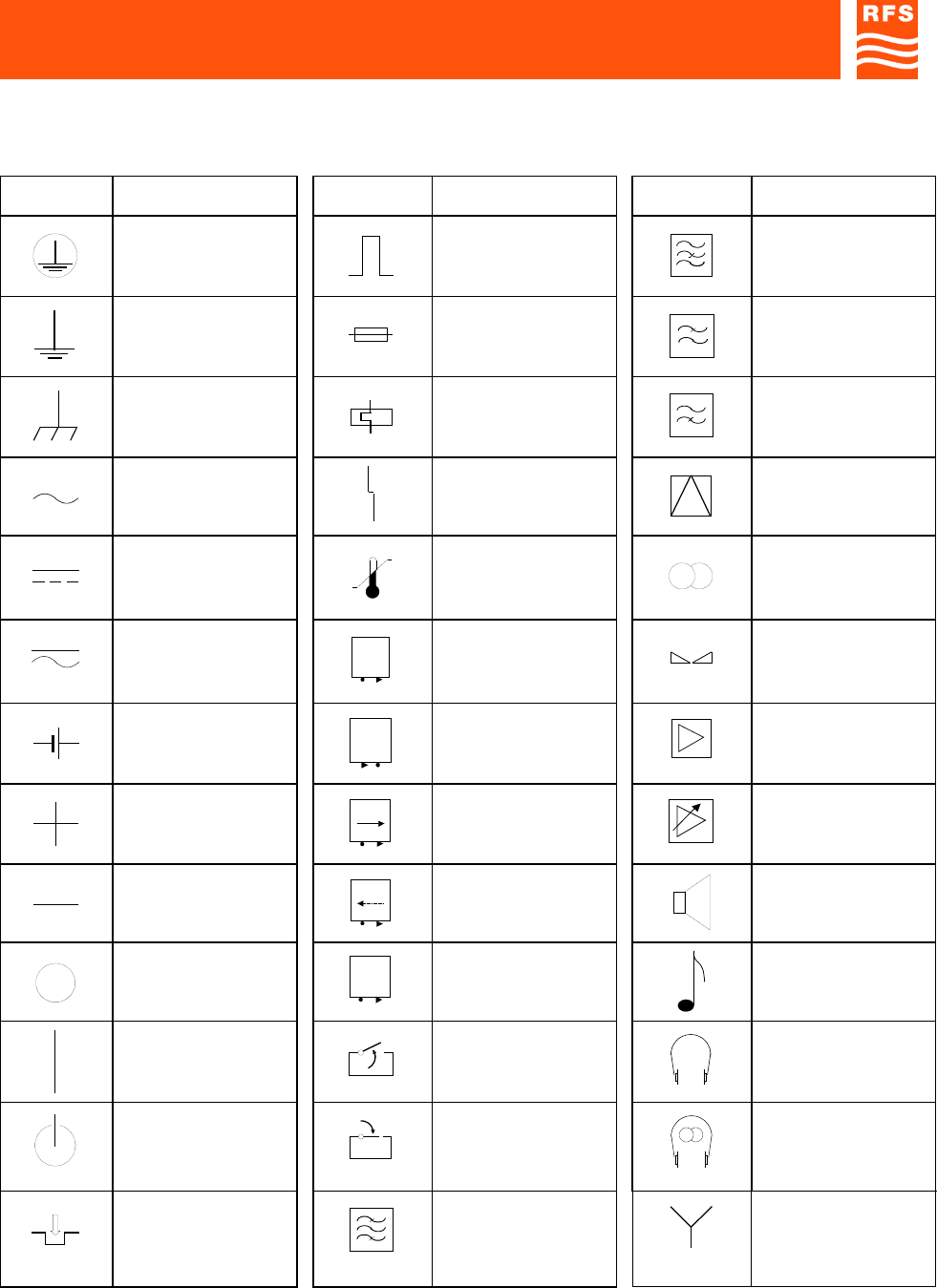
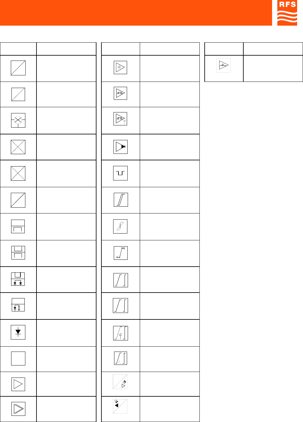
2.2) SYMBOLS
EQUIPMENT FRONT SYMBOLS
SYMBOLS DESCRIPTION SYMBOLS DESCRIPTION SYMBOLS DESCRIPTION
Earth connection Impulsive command Band-stop filter
Ground Fuse Low-pass filter
Chassis ground Thermal breaker High-pass filter
AC Failure Modulator,
demodulator
DC Overtemperature Stereo
Pulse current Output monitoring
signal Balance
Battery / accumulator Input monitoring
signal Amplifier
Positive connector
P
Direct power
monitoring socket Adjustable gain
amplifier
Negative connector
P
Reflected power
monitoring socket Loudspeaker
connection
OFF
L.O.
Local oscillator
monitoring socket Audio connection
ON Gating as opening
criterion Headphone
connection
STAND-BY Gating as closing
criterion Stereo headphone
ON push-button Channel / band filter Star connection
STANDARDS Page 9
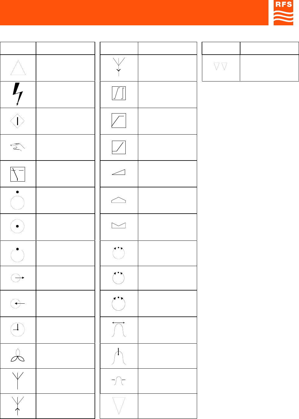
EQUIPMENT FRONT SYMBOLS
SYMBOLS DESCRIPTION SYMBOLS DESCRIPTION SYMBOLS DESCRIPTION
Delta connection Receiving antenna Dual sound
High voltage Linearization
Start push-button Limiter upper
threshold
Local, manual
command Limiter lower
threshold
Automatic Adjusting
OFF / inhibited
(function) Max adjusting
ON / active
(function) Min adjusting
Stand-by
(function) Adjusting
Output connector
f
Frequency adjusting
Input connector
5MHz
Xtal adjusting
Clock display
(operation time
counter)
Freq. tuning
Fan, blower Amplitude tuning
Antenna Band tuning
Transmission antenna Mono
STANDARDS Page 10
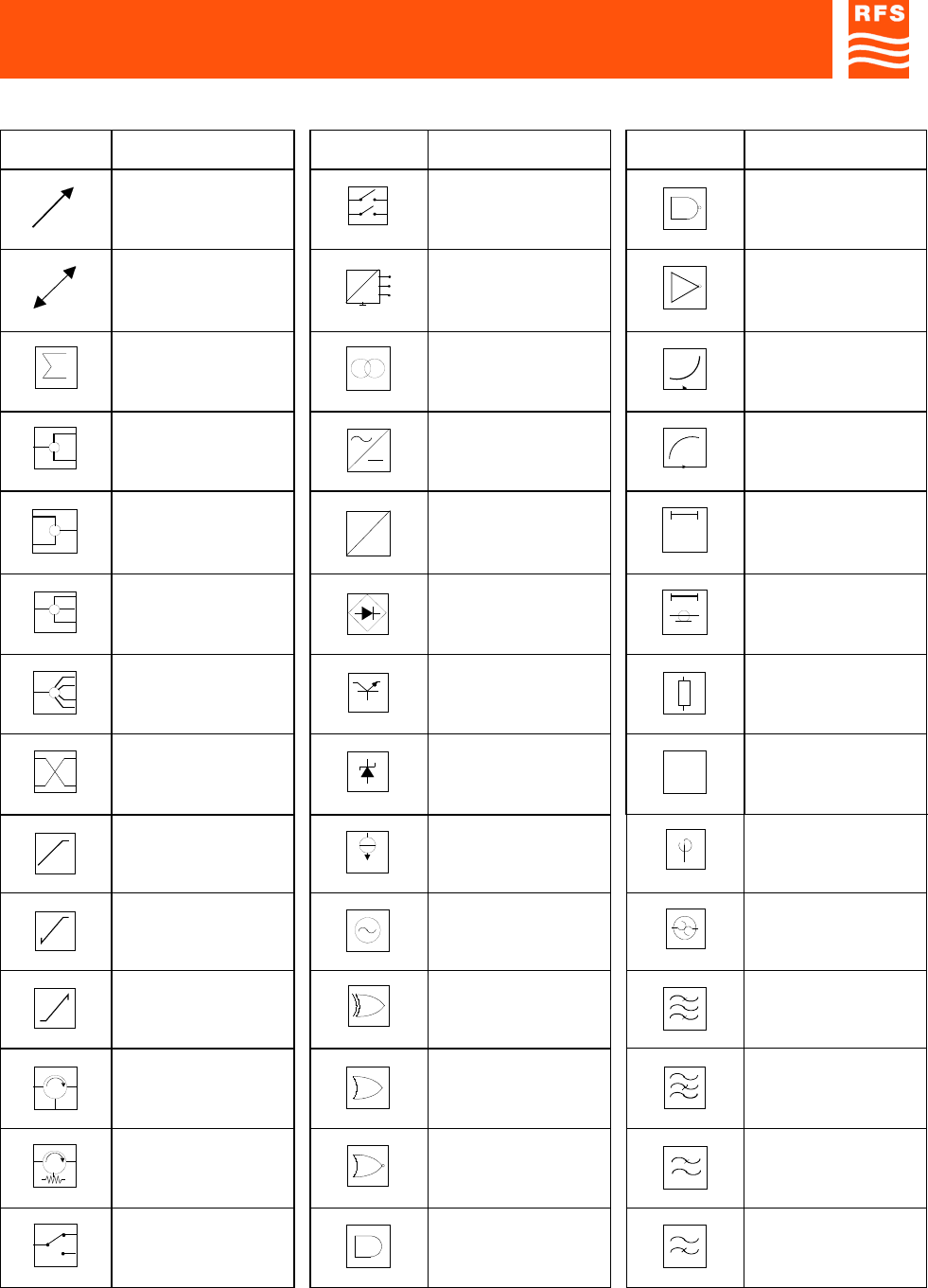
BLOCK DIAGRAM SYMBOLS
SYMBOLS DESCRIPTION SYMBOLS DESCRIPTION SYMBOLS DESCRIPTION
Linear variability 2-way switch NAND general symbol
Automatic adjustment Voltage control
electromagnetic relay NOT general symbol
Combiner general
sign Transformer Preemphasis
2-way power divider Rectifier general
symbol Deenphasis
2-way power
combiner
=
=
DC/DC converter Delay line general
symbol
3-way power divider Bridge rectifier Coaxial type time
delay limiter
4-way power divider
REG
Voltage regulator Resistive attenuator
3dB Hybrid Zener regulator
dB
Pad
LIM.
WHITE
White limiter
BIAS
Constant current bias
device Fixed phase shifter
Positive peak clipper Sinusoidal oscillator
THERMAL
SWITCH
Thermal switch
Negative peak clipper Ex-OR Band-pass filter
Circulator OR general symbol Band-stop filter
Isolator NOR general symbol Low-pass filter
Switch AND general symbol High-pass filter
STANDARDS Page 11
BLOCK DIAGRAM SYMBOLS
SYMBOLS DESCRIPTION SYMBOLS DESCRIPTION SYMBOLS DESCRIPTION
f
f/n
Divider by n DC amplifier Optical amplifier
f
f/n
Multiplier by n Differential
comparator
Mixer general symbol Phase comparator
RF
FI
OL
Up-converter from IF
to RF Detector amplifier
RF FI
OL
Down-converter from
RF to IF
CLAMP
P. SYNC Lamped to the
syncrhronizing signal
peak
f
V
Voltage / frequency
converter Schmitt’s trigger
Directional coupler Amplitude linearity
precorrector
Double directional
coupler Amplitude limiter
without distortion
Directional coupler
with double detector Equalizer general sign
Detector
A
Amplitude equalizer
Peak detector Phase equalizer
XX
3To rise to cubical
power
T
Propagation time
equalizer
Amplifier general
symbol
RF
Laser diode electrical-
optical transmitter
Multistage amplifier
RF
Optical-electrical
receiver

3
1800MHz-1900MHz Off-Air Repeaters (OR Series) Page 91 080 0701F – Rel.04
CHAPTER 3 3.1
3) GENERAL DESCRIPTION
Mobile phone systems have increasingly been spreading in these last years.
Besides providing reliable and good quality connections, telecommunication system services should cover
as widest territory as possible.
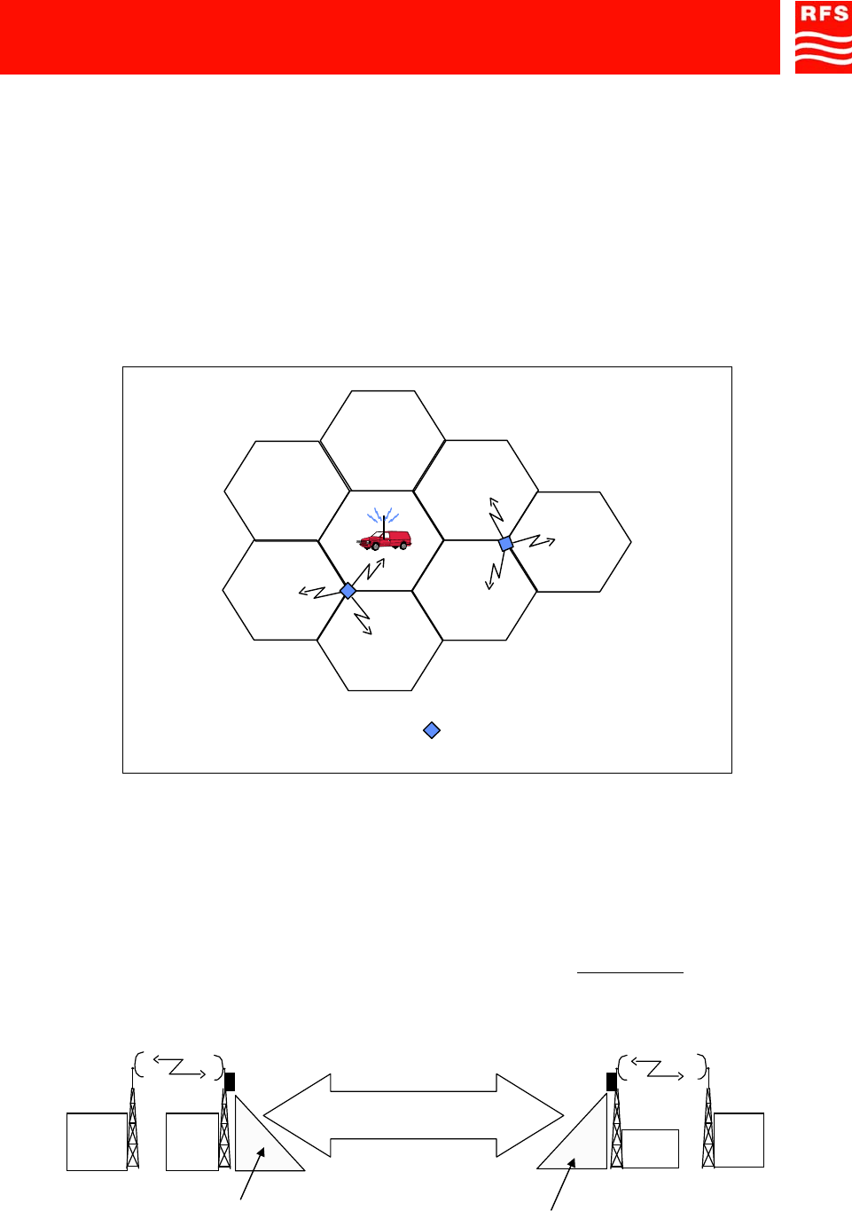
It is well-known that connections to users’ terminals are obtained on air by means of steady stations named
radio bases, located through the whole territory so as to obtain a continuous covering through cells one next
to another.
That allows a great number of users to enter the system using few channels.
It is important to maintain the continuity of radio-electrical coverage (and consequently, of service within
each cell) in order to guarantee an acceptable level of communication.
BTS Tri-cellular
FIGURE 1 – SUBDIVISION OF THE TERRITORY IN CELLS
Off-Air Repeaters are proposed as a valid and economical solution to optimize the cell coverage of the
territory and irradiate shadow area as an alternative to solutions requiring dedicated Radio-Bases (Figure 2).
FIGURE 2 – RADIO-ELECTRICAL PROBLEMS IN CELL NETWORK COVERAGE
Shadow Zone
2Mbit radio connection
MicroBTS solution Repeater solution
BTS
μ
BTS BTS
Source
Re
p
eater
Shadow Zone
The repeater costs are 50% lower
than with the solution
μ
BTS
1800MHz-1900MHz Off-Air Repeaters (OR Series) Page 91 080 0701F – Rel.04
CHAPTER 3 3.2
Off-Air Repeaters on one side receive the signals from the radio base station, amplify them and re-transmit
them in the direction of the shadow area (down-link path). On the other side Off-Air Repeaters receive the
signals from the mobiles (MS), amplify them and re- transmit them to the base station (up-link path).
When a single Off-Air Repeater does not provide satisfactory coverage, the repeater can be used along with
other equipment. Different solutions are provided: cascade systems, based on Bi-Directional Amplifiers, and
optical fibre solutions, based on Remote Units.
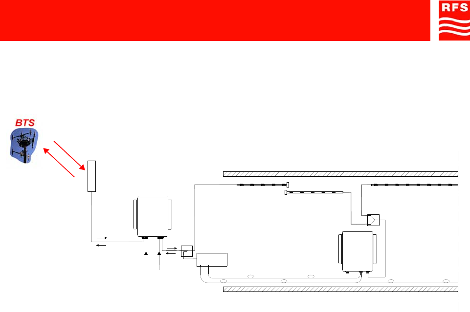
3.1) EXAMPLE: USE IN TUNNELS
The Off-Air Repeater interfaces directly with the BTS of the provider of the services to be extended, and can
be used along with other equipment distributed inside the tunnels. Such equipment can be divided into two
types, according to the radio-coverage system used:
- Bi-directional amplifiers, for cascade systems.
- Remote Units, for optical systems.
The following are a few examples of general projects for radio-electric coverage in tunnels.
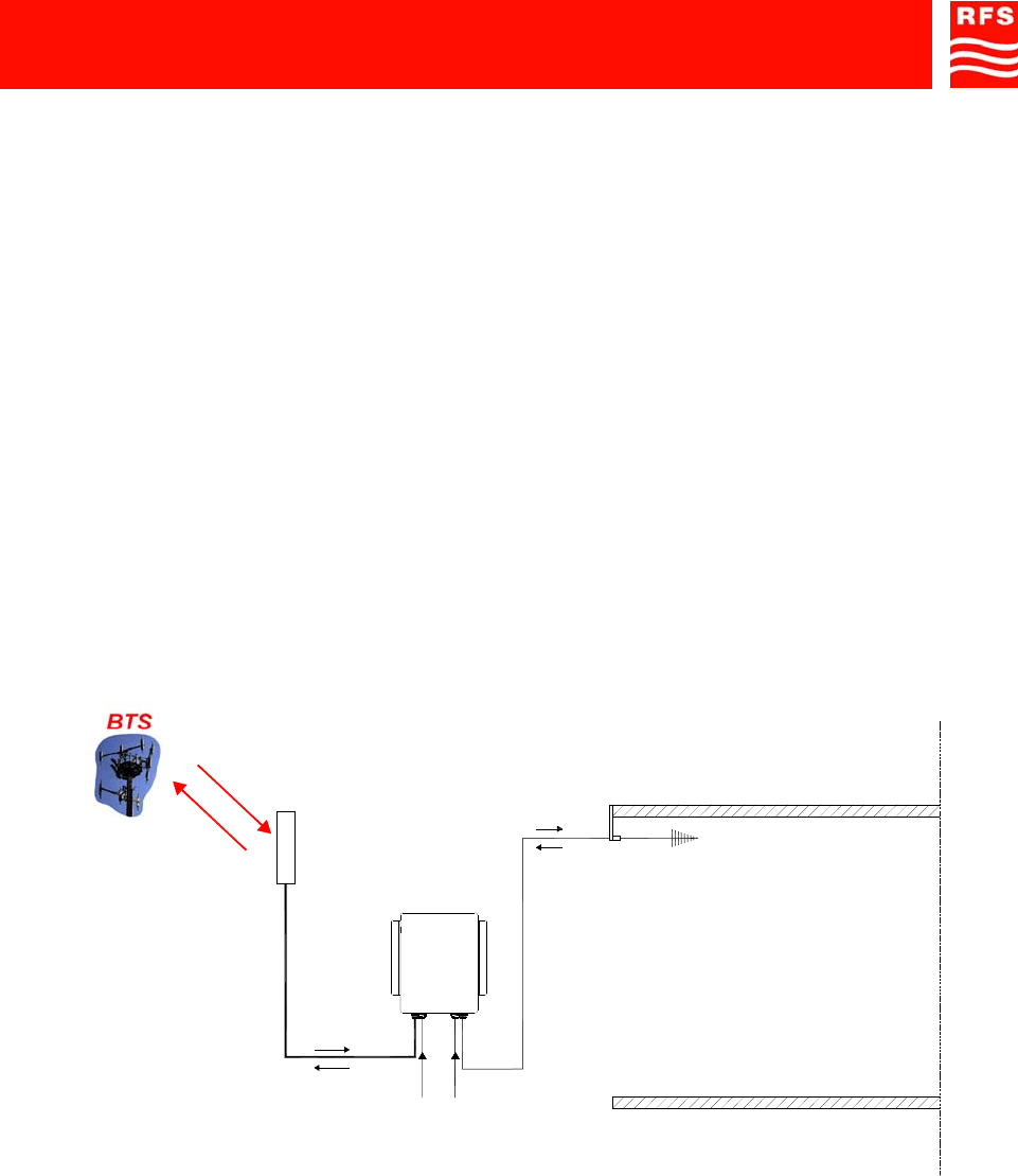
• Tunnels with a length of less than 300 meters.
In this case, one single Off-Air Repeater is sufficient. It is located at the entrance to the tunnel, equipped
with an antenna which irradiates in the direction of the shadow zone (Figure 3).
FIGURE 3
DOWN
UP
DOWN LINK
UP LINK
Power Supply
(230Vac)
OFF-AIR
REPEATER
UP
DOWN
48Vdc Power Supply
and external signals
1800MHz-1900MHz Off-Air Repeaters (OR Series) Page 91 080 0701F – Rel.04
CHAPTER 3 3.3
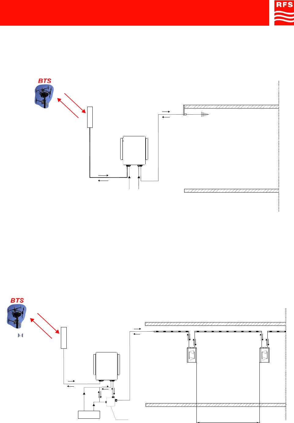
• Tunnels with a length in the 300-meter to 600-meter range.
Also in this case, one single Off-Air Repeater is sufficient. The repeater is located at the entrance to the
tunnel and equipped with a leaky cable. This cable can be combined with a directional antenna to
irradiate a portion of the area in front of the tunnel exit (Figure 4).
FIGURE 4
• Tunnels with a length of more than 600 meters.
The signal can be enhanced in two ways:
a) By an Off-Air Repeater at the entrance to the tunnel, connected to a cascade of bi-directional
amplifiers inside the tunnel which re-generate the signal with amplification steps at a distance of
250mt. ÷ 400mt. from one another (Figure 5).
FIGURE 5
DOWN
UP
DOWN LINK
UP LINK
Power Supply
(230Vac)
OFF-AIR
REPEATER
UP
DOWN
48Vdc Power Supply
and external signals
POWER
SUPPLY
DC
DC BF
RF
BF
RF-DC-BF
RF
UP
DOWN
DOWN
UP
AMPLIFICATION STEP
RF-DC-BF
BI-DIRECTIONAL
AMPLIFIER
RF-DC-BF
RF-DC-BF
RF-DC-BF
DOWN LINK
UP LINK
BI-DIRECTIONAL
AMPLIFIER
Bias-T
OFF-AIR
REPEATER
1800MHz-1900MHz Off-Air Repeaters (OR Series) Page 91 080 0701F – Rel.04
CHAPTER 3 3.4
b) By an Off-Air Repeater connected to master unit and optical remote units with amplification steps of
no more than 1200mt. each. The optical fiber system extends the signal through an antenna or a
passive distribution system (Figure 6).
FIGURE 6
MASTER
UNIT
UP
DOWN
RF
UP
DOWN
DOWN LINK
UP LINK
Power Supply
(230Vac)
48Vdc Power
Supply and external
signals
OFF-AIR
REPEATER
REMOTE
UNIT
1800MHz-1900MHz Off-Air Repeaters (OR Series) Page 91 080 0701F – Rel.04
CHAPTER 3 3.5
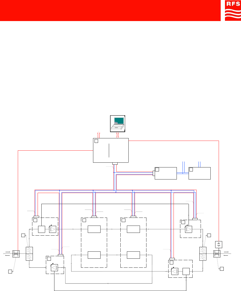
3.2) OPERATING PRINCIPLE – 1800/1900MHz ADJUSTABLE BANDWIDTH OFF-AIR REPEATERS
The repeaters described in this handbook have been developed to permit cell coverage as set forth by the
DCS (Digital Cellular System) standard for cell phones operating on the 1800MHz band or by the PCS
(Personal Communications Service) standard for cell phones operating on the 1900MHz band. The DC
powered repeater can be power-fed by a 48Vdc power supply source only. The AC powered repeater can be
power-fed from MAINS (230Vac) or from a 48Vdc power supply source or both from MAINS and from a
48Vdc source. The presence of both power supply voltages guarantees the continuity of the coverage
service even in case of failure of one source. The commutation is handled automatically by the repeater.
Off-Air Repeaters are bi-directional amplifiers. The signal to be extended follows two distinct paths: the up-
link path, from the mobiles to the radio base station, and the down-link path, from the radio base station
towards the mobiles.
Figure 7 provides a block-diagram of the 1800/1900MHz adjustable band Off-Air Repeater.
FIGURE 7 – 1800/1900MHz OFF-AIR REPEATERS BLOCK-DIAGRAM
In down-link the RF signal from the donor antenna is filtered and pre-amplified by a low-noise amplifier (LNA,
ref. C1).
The selection of the band of frequencies to be extended is handled by two band-selective modules, ref. D1
and ref. D2, which make the band-pass and frequency center programmable entities.
The band of frequencies to be extended can be managed by the user by means of the management system.
The signal is then amplified by the High power amplifier (ref. E1) filtered by the MS side duplexer, ref.
B2,and transmitted by an antenna or a passive distribution system.
A VSWR detector is equipped.
The up-link path is identical to the down-link path described above.
BTS
dB
ALC
dB
ALC
MS
DOWN
UP
DOWN
UP
MANAGEMENT BUS
MANAGEMENT
UNIT
MODEM
NETWORK
RS232
DC/DC
CONVERTER
LNA DOWN HPA
DOWN
LNA UP
HPA UP
BAND SELECTIVE 1
UP LINK
DOWN LINK
BAND SELECTIVE 2
UP LINK
DOWN LINK
5.5Vdc
48Vdc
48Vdc
IN
AC/DC
CONVERTER
230Vac
IN
5.5Vdc
10.5Vdc
10.5Vdc
5.5Vdc
10.5Vdc
5.5Vdc
10.5Vdc
5.5Vdc
5.5Vdc
5.5Vdc
10.5Vdc
5.5Vdc
A1
B1
C1 D1 E1
B2
C2
E2
A2
D2
LF
G

1800MHz-1900MHz Off-Air Repeaters (OR Series) Page 91 080 0701F – Rel.04
CHAPTER 3 3.6
The 48Vdc powered repeater is equipped with a DC/DC converter, ref. F.
The A.C. powered repeater is equipped also with an AC/DC converter, ref. L.
The management module, ref. G, makes it possible to manage the repeater in remote mode via a built-in
modem, or in local mode through the RS232 connector, available on the management module.
The repeater management is performed by means of the Operation and Maintenance Terminal software,
both in local mode and in remote mode (ref. Chap. 4).
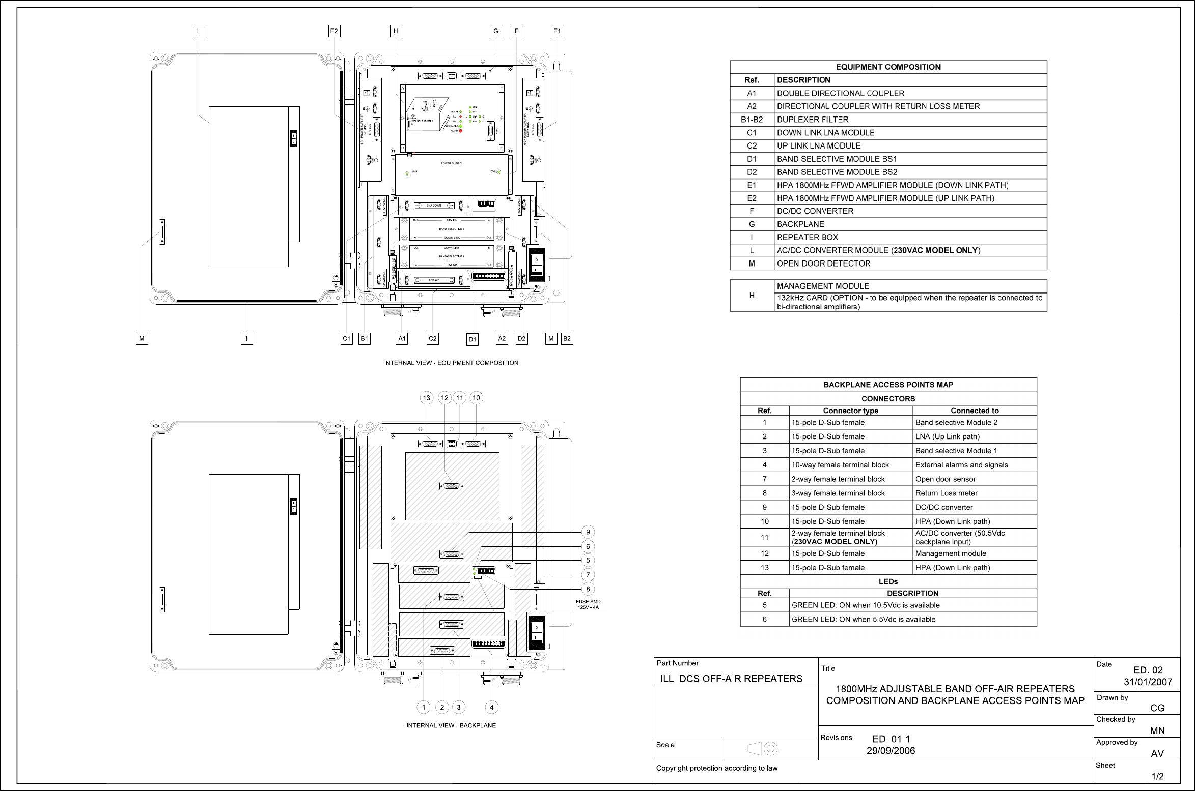
3.3) ATTACHED DOCUMENTS
TECHNICAL CHARACTERISTICS
1800MHz 48Vdc/230Vac ADJUSTABLE BAND OFF-AIR REPEATERS
ILL DCS OFF-AIR REPEATERS (ILLUSTRATIVE DRAWINGS)
Sheet 1, equipment composition and backplane access points map
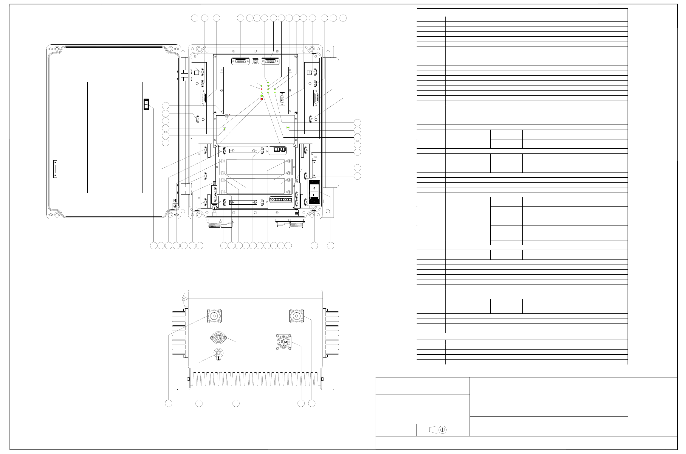
Sheet 2, modules access points map and external access points map
TECHNICAL CHARACTERISTICS
1900MHz 48Vdc/230Vac ADJUSTABLE BAND OFF-AIR REPEATERS
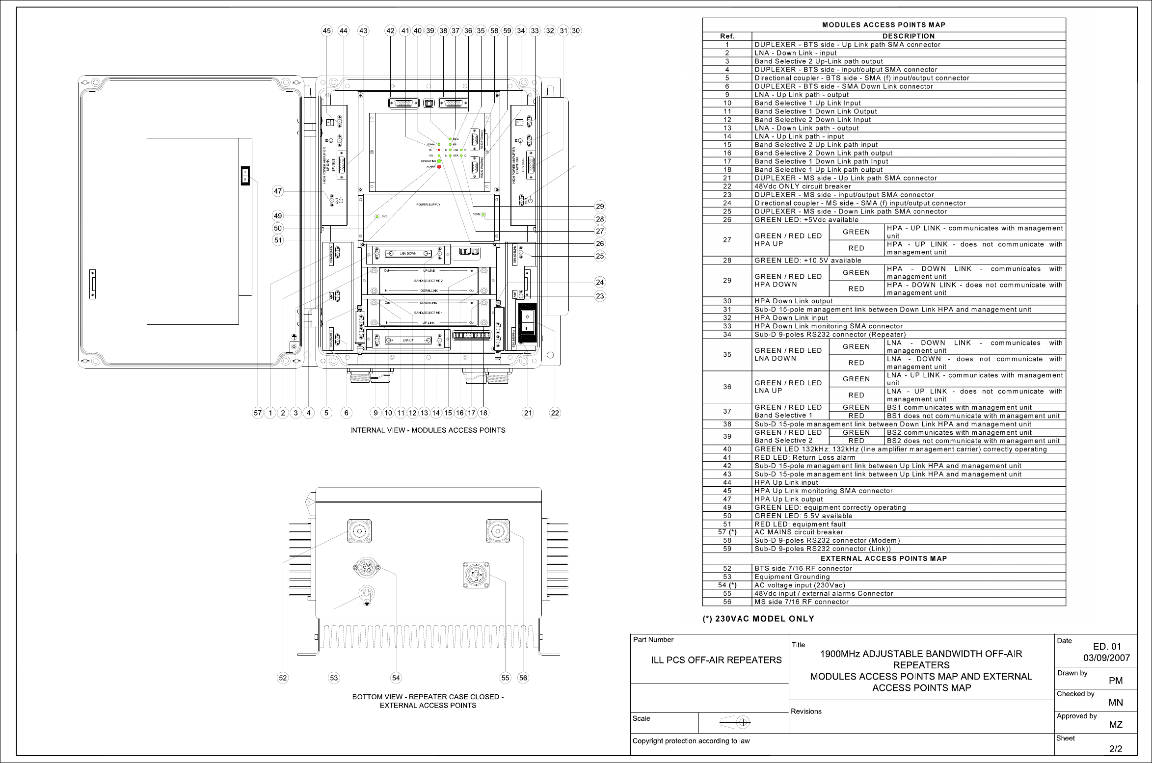
ILL PCS OFF-AIR REPEATERS (ILLUSTRATIVE DRAWINGS)
Sheet 1, equipment composition and backplane access points map
Sheet 2, modules access points map and external access points map

1800MHz-1900MHz ADJUSTABLE BAND Annex TECHNICAL CHARACTERISTICS
OFF-AIR REPEATERS 1
ANNEX 1
TECHNICAL CHARACTERISTICS
TECHNICAL CHARACTERISTICS 1800MHz OFF-AIR
REPEATER
48Vdc MODEL
1800MHz OFF-AIR
REPEATER
230Vac MODEL
Up Link operating frequency band 1710 ÷ 1785MHz
Down Link operating frequency band 1805 ÷ 1880MHz
Number of amplified bands 1
Programmable Bandwidth / steps From 1MHz to 16.5MHz / 10kHz step adjustable
Output Power 28dBm (2 carriers)
3rd Order Intercept Point (OIP3) 57dBm
Output Power at 1dB compression point 36dBm
Noise Figure @ max. gain 8dB
Gain / Step 50 ÷ 80dB / 1dB step
Ripple into operating band ± 2dB
Total processing delay 6μs
Return Loss 14dB
ALC threshold (default value) 3dB over nominal output power
(this value can be changed on site)
Spurious emissions and intermodulation products < -36dBm (in the frequency band 9kHz ÷ 1GHz)
< -30dBm (in the frequency band 1GHz ÷ 12.75GHz)
Local Control Interface RS232
Remote Control Interface PSTN – GSM/DCS modem
Power Supply -72 ÷ -36Vdc -72 ÷ -36Vdc
85÷265Vac (50-60Hz)
Power Consumption 110W @ 48Vdc 140VA @ 230Vac
MTBF 50 000 hours
Operating Temperature (*) -20°C up to +55°C
Degree of protection provided by enclosure IP65
RF connectors 7/16 female
Dimensions (h-w-d) 423x395x230mm
(max. volume - heat sinks included)
Weight 23Kg
All values are typical at 25°C unless otherwise specified
(*) Degraded performances from +50°C to +55°C
1800MHz 48Vdc/230Vac ADJUSTABLE BAND OFF-AIR REPEATERS
MODULES ACCESS POINTS MAP
Ref. DESCRIPTION
1DUPLEXER - BTS side - Up Link path SMA connector
2LNA - Down Link - input
3Band Selective 2 Up-Link path output
4DUPLEXER - BTS side - input/output SMA connector
5Directional coupler - BTS side - SMA (f) input/output connector
6DUPLEXER - BTS side - SMA Down Link connector
9LNA - Up Link path - output
10 Band Selective 1 Up Link Input
11 Band Selective 1 Down Link Output
12 Band Selective 2 Down Link Input
13 LNA - Down Link path - output
14 LNA - Up Link path - input
15 Band Selective 2 Up Link path input
16 Band Selective 2 Down Link path output
17 Band Selective 1 Down Link path Input
18 Band Selective 1 Up Link path output
21 DUPLEXER - MS side - Up Link path SMA connector
22 48Vdc ONLY circuit breaker
23 DUPLEXER - MS side - input/output SMA connector
24 Directional coupler - MS side - SMA (f) input/output connector
25 DUPLEXER - MS side - Down Link path SMA connector
26 GREEN LED: +5Vdc available
GREEN
HPA - UP LINK - communicates with management
unit
27 GREEN / RED LED
HPA UP RED
HPA - UP LINK - does not communicate with
management unit
28 GREEN LED: +10.5V available
GREEN
HPA - DOWN LINK - communicates with
management unit
29 GREEN / RED LED
HPA DOWN RED
HPA - DOWN LINK - does not communicate with
management unit
30 HPA Down Link output
31 Sub-D 15-pole management link between Down Link HPA and management unit
32 HPA Down Link input
33 HPA Down Link monitoring SMA connector
34 Sub-D 9-poles RS232 connector
GREEN
LNA - DOWN LINK - communicates with
management unit
35 GREEN / RED LED
LNA DOWN RED
LNA - DOWN - does not communicate with
management unit
GREEN
LNA - UP LINK - communicates with management
unit
36 GREEN / RED LED
LNA UP RED
LNA - UP LINK - does not communicate with
management unit
GREEN BS1 communicates with management unit
37 GREEN / RED LED
Band Selective 1 RED BS1 does not communicate with management unit
38 Sub-D 15-pole management link between Down Link HPA and management unit
GREEN BS2 communicates with management unit
39 GREEN / RED LED
Band Selective 2 RED BS2 does not communicate with management unit
40 GREEN LED 132kHz: 132kHz (line amplifier management carrier) correctly operating
41 RED LED: Return Loss alarm
42 Sub-D 15-pole management link between Up Link HPA and management unit
43 Sub-D 15-pole management link between Up Link HPA and management unit
44 HPA Up Link input
45 HPA Up Link monitoring SMA connector
46 GSM modem RF output
47 HPA Up Link output RED ON Trying to connect to network
48 RED LED: modem
operation BLINKING
RED Modem correctly operating
49 GREEN LED: equipment correctly operating
50 GREEN LED: 5.5V available
51 RED LED: equipment fault
57 (*) AC voltage ONLY circuit breaker
EXTERNAL ACCESS POINTS MAP
52 BTS side 7/16 RF connector
53 Equipment Grounding
54 (*) AC voltage input (230Vac)
55 48Vdc input / external alarms Connector
56 MS side 7/16 RF connector
(*) 230VAC MODEL ONLY
P
HIGH POWER AMPLIFIER IN
SPV BUS
OUT
UP LINK
LNA DOWN
132KHz
ALARM
+5V
RL
OPERATING
U
ULNA
HPA D
D
BS 1
BS 2
RS232
HIGH POWER AMPLIFIER
SPV BUS
DOWN LINK P
IN
OUT
LNA UP
In
Out
Out
In
BAND-SELECTIVE 1
In
OutIn
Out
DOWN-LINK
UP-LINK
DOWN-LINK
UP-LINK
BAND-SELECTIVE 2
1
45 44 43 42 40 39 33 32 30
4 6 9 10 14 15
23
2111 16 18172 13
52
47
34 3136
29
49
37
223 12
1710-1785MHz
1710-1785MHz 1805-1880MHz
1805-1880MHz
26
38
INTERNAL VIEW - MODULES ACCESS POINTS
BOTTOM VIEW - REPEATER CASE CLOSED
EXTERNAL ACCESS POINTS
POWER SUPPLY
5V5 10V5
50 28
27
51
41 35
25
24
5
46
48
55 56
Copyright protection according to law
ILL DCS OFF-AIR REPEATERS
Scale Revisions
Title
2/2
Sheet
Date
Part Number
1800MHz ADJUSTABLE BAND OFF-AIR REPEATERS
MODULES ACCESS POINTS MAP AND EXTERNAL
ACCESS POINTS MAP Drawn by CG
AV
MN
Approved by
Checked by
57
0
ED. 02
31/01/2007
ED. 01-1
29/09/2006
53 54

1800MHz-1900MHz ADJUSTABLE BAND Annex TECHNICAL CHARACTERISTICS
OFF-AIR REPEATERS 2
ANNEX 2
TECHNICAL CHARACTERISTICS
TECHNICAL CHARACTERISTICS 1900MHz OFF-AIR
REPEATER
48Vdc MODEL
1900MHz OFF-AIR
REPEATER
230Vac MODEL
Up Link operating frequency band 1850 ÷ 1910MHz
Down Link operating frequency band 1930 ÷ 1990MHz
Number of amplified bands 1
Programmable Bandwidth / steps From 1MHz to 16.5MHz / 10kHz step adjustable
Output Power (GSM/TDMA) 31dBm (1 carrier)
28dBm (2 carriers)
25dBm (4 carriers)
Output Power (CDMA) 26dBm (1 carrier)
23dBm (2 carriers)
20dBm (4 carriers)
3rd Order Intercept Point (OIP3) 57dBm
Output Power at 1dB compression point 36dBm
Noise Figure @ max. gain 8dB
Gain / Step 50 ÷ 80dB / 1dB step
Ripple into operating band ± 2dB
Total processing delay 6μs
Return Loss 14dB
ALC threshold (default value) 3dB over nominal output power
(this value can be changed on site)
Spurious emissions and intermodulation products < -13dBm (in the frequency band 9kHz ÷ 1GHz)
< -13dBm (in the frequency band 1GHz ÷ 12.75GHz)
Local Control Interface RS232
Remote Control Interface PSTN – GSM (850, 900, 1800, 1900)
or CDMA (850, 1900) modem
Power Supply -72 ÷ -36Vdc -72 ÷ -36Vdc
85÷265Vac (50-60Hz)
Power Consumption 110W @ 48Vdc 140VA @ 230Vac
MTBF 50 000 hours
Operating Temperature (*) -20°C up to +55°C
Degree of protection provided by enclosure IP65
RF connectors 7/16 female
Dimensions (h-w-d) 423x395x230mm
(max. volume - heat sinks included)
Weight 23Kg
All values are typical at 25°C unless otherwise specified
(*) Degraded performances from +50°C to +55°C
1900MHz 48Vdc/230Vac ADJUSTABLE BAND OFF-AIR REPEATERS


4
1800MHz-1900MHz Off-Air Repeaters (OR Series) Page 91 080 0701F – Rel.04
CHAPTER 4 4.1
4) INSTALLATION AND POWER-UP PROCEDURES
Ref.: ILL DCS OFF-AIR REPEATERS / ILL PCS OFF-AIR REPEATERS
WARNING:
Before installing the equipment, carefully read the safety norms herewith attached.
A correct repeater installation and setting procedure requires a good knowledge and experience in
installing telecommunication equipment. These activities should be performed by skilled personnel
only. Remember that if the equipment is not installed correctly, it may:
- put the donor BTS temporary out of service,
- be damaged by excessively high input or output signal levels.
4.1) INSTALLATION
1. INITIAL CHECK
Make sure that the supply is complete and/or that the material has not been damaged during transport.
The list of the materials that make up the equipment is described in the relative PACKING LIST.
Should any parts be missing, or should some be damaged, kindly inform the Sales Dept. of RFS
immediately, in order to facilitate replacing and/or repairing the parts involved.
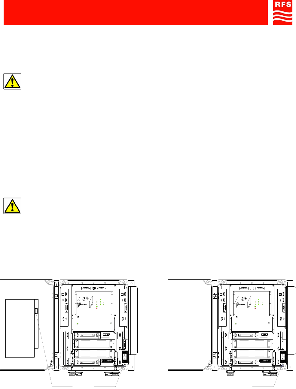
WARNING:
Before installing the equipment, always make sure that the repeater is not powered up:
- Check that both ON/OFF switches located inside the alternate current powered repeater are
in the OFF position (AC voltage circuit breaker, ref. 59 and 48Vdc circuit breaker, ref. 22
FIGURE 1a).
- Check that the ON/OFF switch (48Vdc circuit breaker, ref. 22, FIGURE 1b) located inside the
direct current powered repeater is in the OFF position.
The LEDs inside the repeater must be turned off.
FIGURE 1 – EQUIPMENT POWER SWITCHES
AC voltage
circuit breaker
ref. 59
a) 230Vac MODEL
INTERNAL VIEW b) 48Vdc MODEL
INTERNAL VIEW
48Vdc circuit
breaker
ref. 22
P
HIGH POWER AMPLIFIER IN
SPV BUS
OUT
UP LINK
132KHz
ALARM
+5V
RL
OPERATING
U
ULNA
HPA D
D
BS 1
BS 2
HIGH POWER AMPLIFIER
SPV BUS
DOWN LINK P
IN
OUT
In
Out
Out
In
BAND-SELECTIVE 1
In
Out
In
Out
DOWN-LINK
UP-LINK
DOWN-LINK
UP-LINK
BAND-SELECTIVE 2
1710-1785MHz1805-1880MHz
1710-1785MHz 1805-1880MHz
POWER SUPPLY
5V5 10V5
LNA DOWN
LNA UP
0
48Vdc circuit
breaker
ref. 22
1800MHz-1900MHz Off-Air Repeaters (OR Series) Page 91 080 0701F – Rel.04
CHAPTER 4 4.2
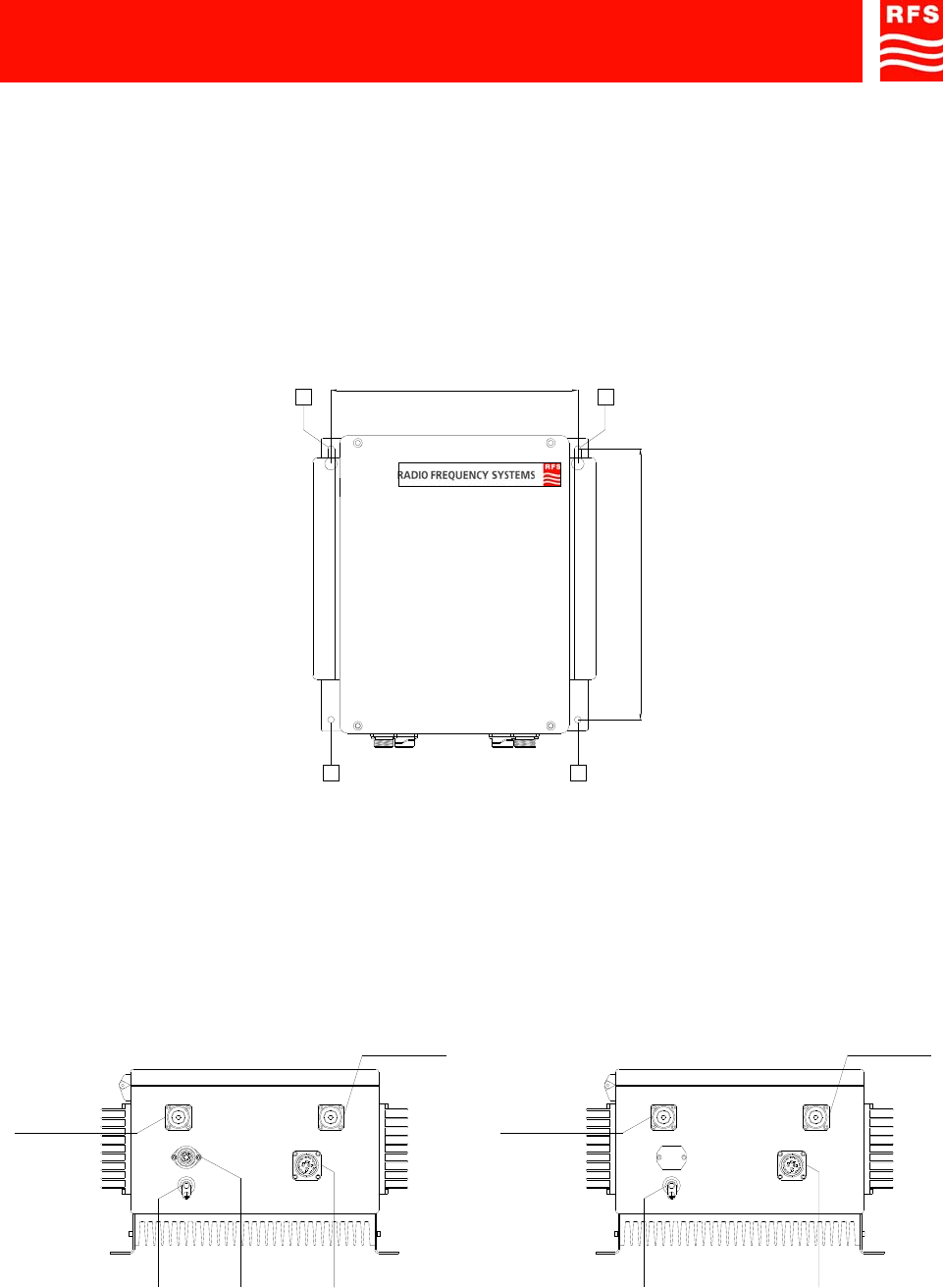
2. POSITIONING THE REPEATER
The Off-Air Repeater is housed inside a case which provides high-degree environmental protection (IP65).
Therefore it is suitable for outdoor wall mount installation. It can also be installed inside specific cabinets
equipped with UPS units.
Fix the Off-Air Repeater in vertical position on the wall, or on the vertical guides present inside the cabinet:
• Lift the equipment and fix its position with four M8 bolts, which are to be inserted in the pre-cut slots
(ref. A, FIGURE 2).
• After checking the correct positioning of the equipment, fully tighten the bolts.
FIGURE 2 - POSITION OF THE HOLES IN THE SUPPORT BRACKETS FOR THE EQUIPMENT
3. POWER SUPPLY SOURCE CONNECTIONS AND ALARMS CONNECTIONS
• Before carrying out any other electrical connection connect the rack to the station ground, using the
ground bolt on the bottom of the repeater (ref. 53, FIGURE 3).
• Make sure that the power supply source provides the prescribed nominal voltage.
If so, connect the equipment to the power supply source, as described below.
FIGURE 3 – EXTERNAL CONNECTORS
334.00 mm (13.15 in.)
366.00 mm (14.41 in.)
A A
AA
Equipment
Grounding
ref. 53
BTS side
RF connector
ref. 52
AC voltage input
from MAINS
ref. 54
MS side
RF connector
ref. 56
a) 230Vac MODEL
BOTTOM VIEW b) 48Vdc MODEL
BOTTOM VIEW
48Vdc input and
external alarms
Connector
ref. 55
Equipment
Grounding
ref. 53
BTS side
RF connector
ref. 52
MS side
RF connector
ref. 56
48Vdc input and
external alarms
Connector
ref. 55
1800MHz-1900MHz Off-Air Repeaters (OR Series) Page 91 080 0701F – Rel.04
CHAPTER 4 4.3
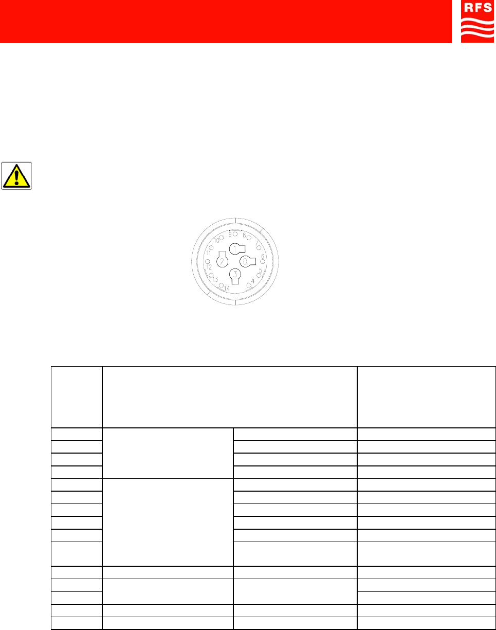
• D.C. POWERED EQUIPMENT
- Connect the 15-pole (f) connector on the bottom of the repeater (ref. 55, FIGURE 3) to the 48Vdc/Alarm
cable (supplied with the equipment).
The cable permits D.C power supply (48Vdc) to the equipment. It also makes available the remote
signals detailed into Table 1.
- Connect the cable to the power supply source (48Vdc) and connect the external signals.
PLEASE NOTE:
The 48Vdc power supply cable (also including the external alarms), provided standard with the
equipment, must never be longer than 3 meters in length (connectors included).
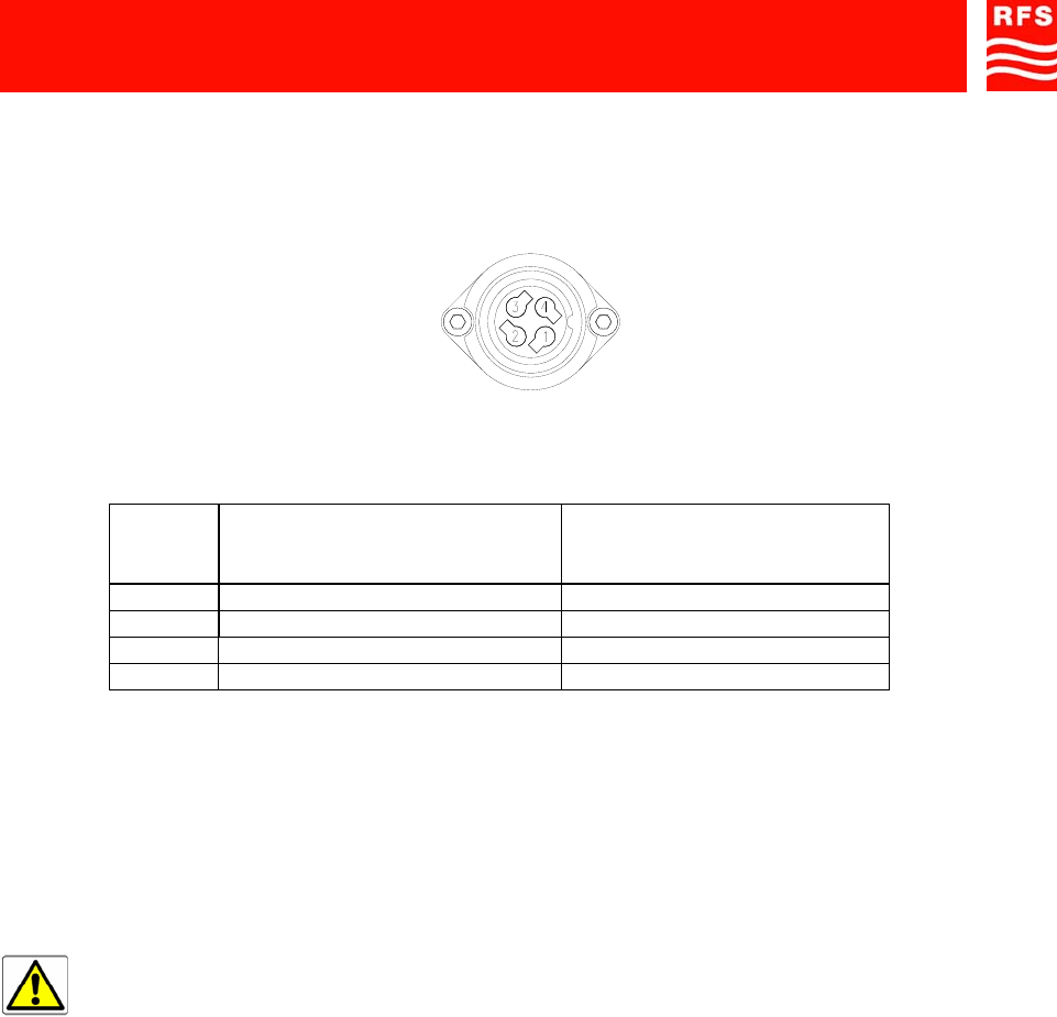
48Vdc POWER SUPPLY AND EXTERNAL ALARMS CONNECTOR
PIN TYPE OF SIGNAL
WIRES COLOR OF 48VDC
POWER SUPPLY AND
EXTERNAL ALARMS
CABLE
0 0Vdc RED
1 0Vdc RED
2 - 48Vdc BLACK
3
48Vdc
POWER SUPPLY
- 48Vdc BLACK
4 EXTERNAL ALARM 3 GRAY
5 EXTERNAL ALARM 4 BROWN
6 EXTERNAL ALARM 2 ORANGE
7 EXTERNAL ALARM 1 PINK
8 GROUND - GND GREEN
9
EXTERNAL ALARMS
+5Vdc EXT. ALM.
COMMON WHITE
10 NOT CONNECTED
11 BLUE
12
SPV CARRIER FOR BDAs
(IF ANY) 132kHz VIOLET
13 NOT CONNECTED
14 NOT CONNECTED
TABLE 1 – 48Vdc POWER SUPPLY AND REMOTE SIGNALS CONNECTOR PIN-OUT
1800MHz-1900MHz Off-Air Repeaters (OR Series) Page 91 080 0701F – Rel.04
CHAPTER 4 4.4
• AC POWERED EQUIPMENT (ALTERNATE CURRENT)
- Connect the 230Vac power cable to the connector located on the bottom of the repeater (ref. 54,
FIGURE 3). The connector pin assignments is detailed in Table 2.
230Vac POWER SUPPLY CONNECTOR
PIN CABLE 230VAC POWER SUPPLY
CABLE COLOR
1 LINE BROWN
2 NEUTRAL BLUE
3 GROUND (GND) YELLOW / GREEN
4 NOT CONNECTED
TABLE 2 – 230Vac POWER SUPPLY CONNECTOR PIN-OUT
- Connect the other end of the cable to the power supply source (230Vac).
- Also connect the 48Vdc power and alarms cable, provided standard, to the 15-pin connector located on
the bottom of the equipment (ref. 55, FIGURE 3).
The cable makes remote signals available. The connector pin-out is detailed into table 1.
The cable can also be connected to a 48Vdc power supply, to feed the equipment with a D.C. voltage.
PLEASE NOTE:
The 48Vdc power supply cable (also including the external alarms), provided standard with the
equipment, must never be longer than 3 meters in length (connectors included).
1800MHz-1900MHz Off-Air Repeaters (OR Series) Page 91 080 0701F – Rel.04
CHAPTER 4 4.5
4.2) POWER-UP
Warning: before power up, make sure that the isolation between the donor antenna and the
service antenna is at least 15dB greater than the repeater gain.
1. Connect the cable from the donor antenna to a spectrum analyzer and check input signal presence and
level. After measurement disconnect the spectrum analyzer.
2. Switch on the equipment by means of the switches placed inside the repeater (FIGURE 1a and b).
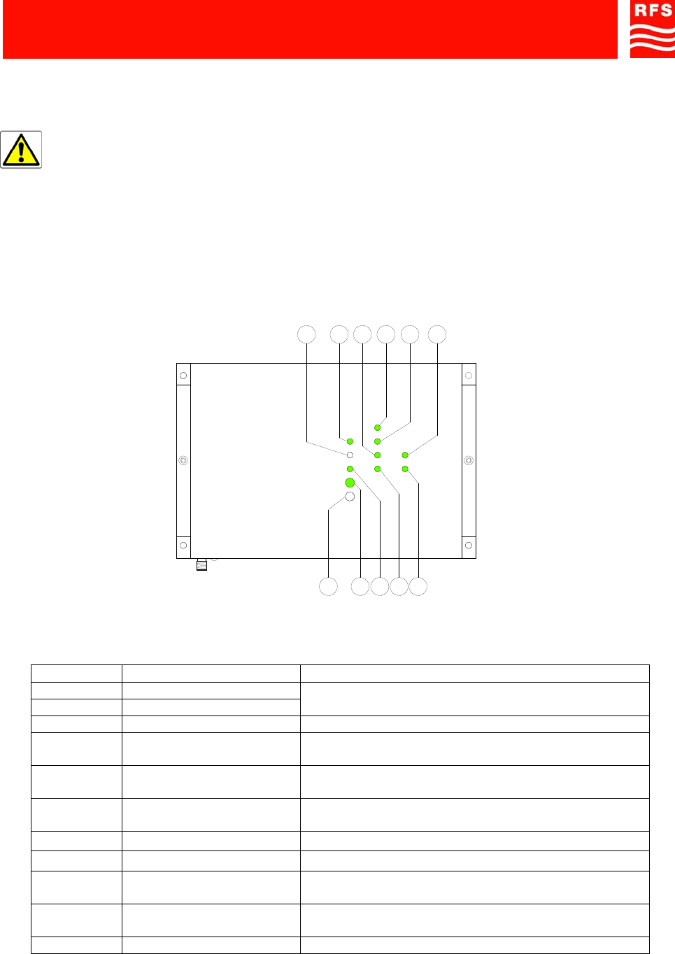
3. Check the LEDs status on the management module: FIGURE 4 and Table 3 show LEDs status on the
management module under normal operating conditions.
FIGURE 4 – MANAGEMENT MODULE: LEDS STATUS - CORRECT POWER UP
REF. STATUS MEANING
LED 1S OFF
LED 2S ON Equipment correctly operating
LED 3S ON Management module: +5Vdc available
LED 4S ON, GREEN HPA (High Power Amplifier) - UP LINK -
communicates with management module
LED 5S ON, GREEN HPA (High Power Amplifier) - DOWN LINK -
communicates with management module
LED 6S ON, GREEN LNA (Low Noise Amplifier) - DOWN LINK -
communicates with management module
LED 7S ON, GREEN BS1 communicates with management module
LED 8S ON, GREEN BS2 communicates with management module
LED 9S ON, GREEN LNA (Low Noise Amplifier) - UP LINK - communicates
with management module
LED 10S ON, GREEN 132kHz correctly operating
LED 11S OFF NO Return Loss alarm
TABLE 3 - MANAGEMENT MODULE: LEDS STATUS - CORRECT POWER UP
11S
1S 2S 4S3S 5S
U
U
RL
OPERATING
+5V
ALARM
132KHz
DLNA
HPA D
BS 2
BS 1
6S10S 9S 8S 7S
1800MHz-1900MHz Off-Air Repeaters (OR Series) Page 91 080 0701F – Rel.04
CHAPTER 4 4.6
4. Check that the green LED on the 230Vac power supply module (when equipped) is ON (ref. 60, ILL
DCS OFF-AIR REPEATERS, sheet 2).
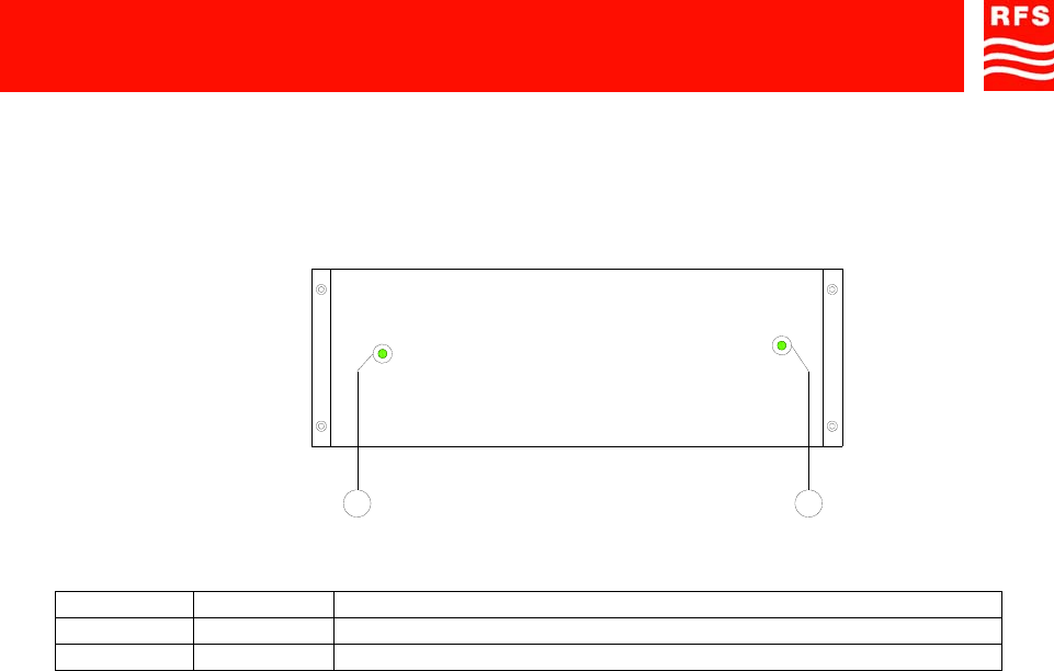
5. Check LEDs status on the 48Vdc power supply module: FIGURE 5 and Table 4 show LEDs status on
the power supply module (DC/DC converter) under normal operating conditions.
FIGURE 5 – DC/DC CONVERTER: LEDS STATUS - CORRECT POWER UP
REF. STATUS MEANING
LED 1A ON 5.5Vdc from DC/DC converter available
LED 2A ON 10.5Vdc from DC/DC converter available
TABLE 4 - DC/DC CONVERTER: LEDS STATUS - CORRECT POWER UP
POWER SUPPLY
5V5 10V5
1A 2A
1800MHz-1900MHz Off-Air Repeaters (OR Series) Page 91 080 0701F – Rel.04
CHAPTER 4 4.7
6. WIRELESS MODEMS
a. Models equipped with CDMA modem
data communication between repeater (via built-in CDMA modem) and management workstation
(PC where OMT/OMC management softwares have been previously installed) via PSTN and/or
CDMA modem, must be established in CSD (CIRCUIT-SWITCHED DATA) mode only. All other
modalities are not allowed.
As CDMA modems don’t use SIMs, the network’s parameters have to be set manually by using the
HyperTerminal. Please contact your local Operator, communicating modem’s ESN (check the sticker at the
top of the management module), to get the needed parameters. Most common parameters are:
Typical CDMA Network Parameters
Acronyms Full name Network's setting /
Terminal's setting Description Notes
MSL Master Subsidy
Lockcode Provided by the Operator Modem lock / unlock code -
MDN Mobile Data Number Provided by the Operator Modem phone number MDN & MTN are
synonyms
MTN Mobile Telephone
Number Provided by the Operator Modem phone number MDN & MTN are
synonyms
MNC Mobile Network Code Provided by the Operator 2 digit number that represents a
sub-network in the IMSI -
MCC Mobile Country Code Provided by the Operator Predefined number that
represents a Country in the IMSI -
ESN Electronic Serial Number Proprietary of the modem
(factory setting) Modem internal proprietary ID
(factory setting)
It can be found into the
sticker at the top of the
management module
MIN Mobile Identification
Number Provided by the Operator Subscriber's account number -
IMSI International Mobile
Subscription Identity Provided by the Operator International modem ID IMSI = MCC + MNC +
MIN
(Home) SID System ID Provided by the Operator ID of the sub-network where
modem can operate SID & NID are synonyms
(Home) NID Network ID Provided by the Operator ID of the sub-network where
modem can operate SID & NID are synonyms
PRI Product Release
Instruction Provided by the Operator Carrier information -
PRL Preferred Roaming List Provided by the Operator List of NIDs/SIDs -
PCA Primary Channel A Provided by the Operator RF primary channel -
PCB Primary Channel B Provided by the Operator RF primary channel -
SCA Secondary Channel A Provided by the Operator RF secondary channel -
SCB Secondary Channel B Provided by the Operator RF secondary channel -
A-key Autenthification key Provided by the Operator Key for the autenthification Built-in modem's one is
random
Note: not all parameters could be needed
In normal operating conditions the jumper must remain connected (if removed, the remote management will
be avoided). It can be temporary removed to set the Operator’s parameters into the built-in modem by using
the RS232 modem port. The same serial cable used for local management, can be used to set the modem.
Once the modem setting is complete, reconnect the jumper to the normal operating position.

1800MHz-1900MHz Off-Air Repeaters (OR Series) Page 91 080 0701F – Rel.04
CHAPTER 4 4.8
The following procedure explains how to set the modem’s parameters.
Please note: AT commands, contained between the inverted commas, must be strictly typed as it follows.
1) Switch-off the repeater
2) Remove the jumper at RS232 (modem) connector
3) Connect the serial cable (supplied with repeater) with your laptop and RS232 (modem) connector
4) Switch-on the repeater and wait for the complete auto-diagnostic test
5) Run HyperTerminal software on your laptop (if you’re using Microsoft XP, run HyperTerminal from
start/programs/accessories/communication/HyperTerminal)
6) Type the connection’s name (e.g. repeater’s modem) and press OK
7) Chose the right PC’s serial port (COM) and press OK
8) Set the bit-rate at “9600” baud
9) Set the number of bits at “8”
10) Set the parity at “no parity”
11) Set the bit stop at “1”
12) Set the flow control at “no flow control”
13) Press OK
14) Type “AT” and press ENTER (modem should reply with “OK”)
15) Type “AT+E1” and press ENTER (modem should reply with “OK”)
16) Type “AT+CGSN” and press ENTER to display the ESN number (if needed)
17) Type “AT+WSPC=1,000000” and press ENTER to get access to CDMA AT commands
18) Type “AT+WMDN=xxx” where xxx is the MDN number (10 to 15 digits) and press ENTER
If needed, to get current MDN number, type “AT+WMDN?” and press ENTER
19) Type “AT+WIMI=xxx” where xxx is the IMSI number (15 digits) and press ENTER
If needed, to get current IMSI number, type “AT+WIMI? and press ENTER
20) Type “AT+WSID=, xxx, yyy” where xxx is the SID number (1 up to 5 digits / 0 up to 32767) and yyy
is the NID number (1 up to 5 digits / 0 up to 65535 – if not provided, set 65535) and press ENTER
If needed, to get current IMSI number, type “AT+WIMI? and press ENTER
With the this command you’ve set SID & NID number in first memory location. Up to 20 (0 up to 19)
locations are supported. To set other SIDs & NIDs, please use the following sintax:
Type “AT+WSID=zz, xxx, yyy” where zz is the location (up to 2 digits / 1 up to 19) where these SIDs
& NIDs have to be stored, xxx is the SID number (1 up to 5 digits / 0 up to 32767) and yyy is the NID
number (1 up to 5 digits / 0 up to 65535 – if not provided, set 65535) and press ENTER
Please note: to set both SID & NID at 0 in location 2, type “AT+WSID=2”
21) Type “AT+WPCC=xxx,yyy” where xxx is primary channel “a” (up to 4 digits / 0 up to 2047) and yyy
is primary channel “b” (up to 4 digits / 0 up to 2047) and press ENTER
If needed, to get current primary channels, type “AT+WPCC? and press ENTER
22) Type “AT+WSCC=xxx,yyy” where xxx is secondary channel “a” (up to 4 digits / 0 up to 2047) and
yyy is secondary channel “b” (up to 4 digits / 0 up to 2047) and press ENTER
If needed, to get current secondary channels, type “AT+WSCC? and press ENTER
23) Type “AT+WCMT=1” and press ENTER to store these settings into the modem. The modem will be
automatically re-start with new settings. Please wait for 10-20 seconds prior to type other commands
24) Type “AT” and press ENTER (modem should reply with “OK”)
25) Type “AT+E1” and press ENTER (modem should reply with “OK”)
26) Type “AT+CICB=0” and press ENTER to allow CSD data connections
27) Close the HyperTerminal
28) Remove the serial cable
29) Switch-off the equipment
30) Reconnect the existing jumper cable with RS232 (modem)
Please note: not all the above mentioned parameters could be necessary. For any problem, please contact
our local subsidiary.
1800MHz-1900MHz Off-Air Repeaters (OR Series) Page 91 080 0701F – Rel.04
CHAPTER 4 4.9
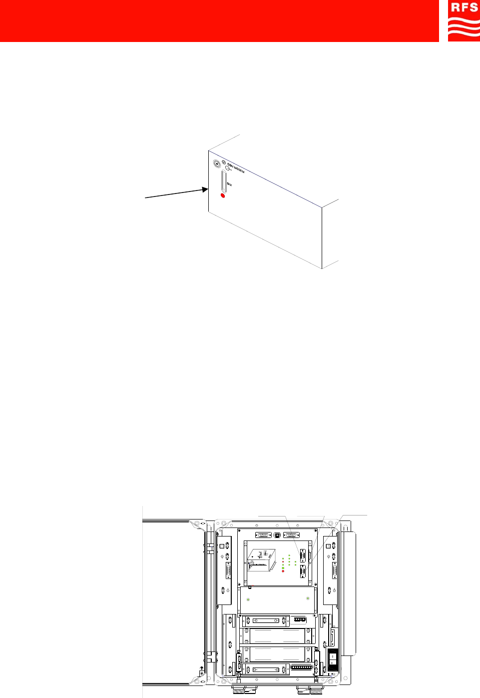
b. Models equipped with GSM modem
How to install/remove the SIM card from the built-in modem
• Open the repeater.
• Check that the switches inside the repeater are set to 0 - OFF (FIGURE 1a and b).
• Insert the SIM enabled to data transmission in not transparent mode 9600BPS (FIGURE 6)
FIGURE 6 – DETAIL OF THE SIM INSERTION
• Close the Management Module
• Switch on the equipment (AC voltage circuit breaker, ref. 57, 48Vdc circuit breaker, ref. 22, FIGURE
1a-b).
• Close the repeater.
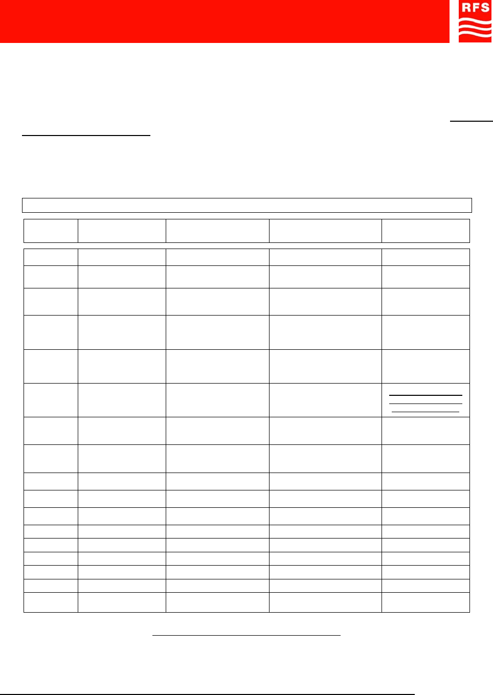
7. INSTALL THE OPERATION AND MAINTENANCE SOFTWARE OMT REPEATER
Install on your PC the Operation and Maintenance Terminal software to set and manage the equipment
(please refer to the software User’s manual). The repeater can be managed in remote mode via a built-
in modem, or in local mode.
8. START OMT Repeater IN LOCAL MODE
In LOCAL mode the notebook is connected to the repeater via RS232 serial cable.
- Open the repeater door (by unscrewing four screws located on the equipment front door).
Connect your notebook to the management module (connector RS232, ref. 34, FIGURE 7) using the provided
serial cable (null-modem type).
P
HIGH POWER AMPLIFIER IN
SPV BUS
OUT
UP LINK
132KHz
ALARM
+5V
RL
OPERATING
U
ULNA
HPA D
D
BS 1
BS 2
HIGH POWER AMPLIFIER
SPV BUS
DOWN LINK P
IN
OUT
In
Out
Out
In
BAND-SELECTIVE 1
In
OutIn
Out
DOWN-LINK
UP-LINK
DOWN-LINK
UP-LINK
BAND-SELECTIVE 2
POWER SUPPLY
5V5 10V5
LNA DOWN
LNA UP
RS232 (Repeate r) RS232 (Modem )
RS232
Modem
ref. 58
RS232
Link
ref. 59
RS232
Repeater
ref. 34
FIGURE 7 – RS232 CONNECTORS
1800MHz-1900MHz Off-Air Repeaters (OR Series) Page 91 080 0701F – Rel.04
CHAPTER 4 4.10
- The connector RS232 (ref. 58,FIGURE 7) and the connector RS232 (ref. 59, FIGURE 7) are
connected with a cable (only in models equipped with CDMA modem).
- Switch on your notebook and start Windows.
- To Run the program select the related folder in the Windows ‘Start’ menu and click.
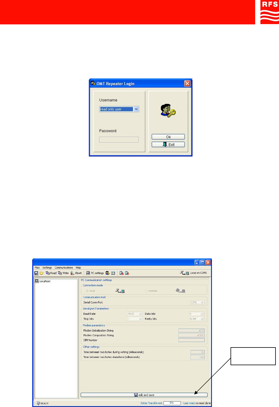
- The ‘Login panel’ is displayed (FIGURE 8).
FIGURE 8 – LOGIN PANEL
- Select read/write user.
PLEASE NOTE It’s not requested to insert the password the first opening of the program. It’s recommended
to change the password to avoid undesired accesses to the program (to change the password, please refer
to the Operation and Maintenance Terminal Software User’s manual).
- Click ‘Ok’ to start the software.
The window ‘Communication settings’ is displayed: check that local ‘Connection mode’ is selected.
If remote Connection mode is selected it is possible to change the Connection mode as follows:
- select the ‘Edit and save’ button in the lower part of the panel to enable changes;
- select local Connection mode;
- press the ‘Edit and save’ button again to confirm.
FIGURE 9 – ‘COMMUNICATION SETTINGS’ PANEL
Edit and save
button
1800MHz-1900MHz Off-Air Repeaters (OR Series) Page 91 080 0701F – Rel.04
CHAPTER 4 4.11
9. SET THE REPEATER GAIN, FREQUENCY CENTER AND BANDWIDTH
- Select the menu entry ‘Read’ in the ‘Device’ menu, or click the ‘ Read’ button, to read the
equipment configuration and status.
The software main window is displayed.
By means of the software set the repeater gain as described below.
NOTE
How to modify parameters:
- Click on the ‘edit and save’ button, in the lower part of the window, to enable changes to the repeater
parameters.
- Click again on the ‘edit and save’ button to save changes.
- The menu entry ‘Write’, in the ‘Device’ menu, makes it possible to apply changes to the repeater. A
password is required: default password is blank. To change the password please refer to the
software User’s manual.
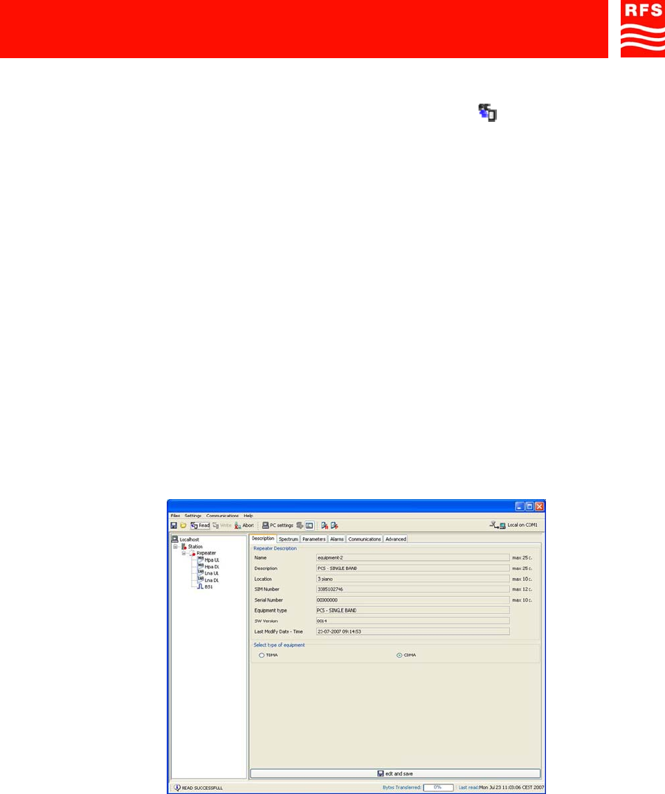
a) In the tree structure of the repeater system (FIGURE 9) select the repeater (double click on
‘Repeater’): on the right side of the window, the configuration and status panels of the repeater
will be shown (Description, Spectrum, Parameters, Alarms, Communications, Advanced).
b) In the description panel, the user should select ( FIGURE 10) if the system is TDMA or CDMA.
This selection allows to load the right values of RF power transmitted by the HPAs (only for
1900MHz repeaters)
.
FIGURE 10 – Selection TDMA / CDMA
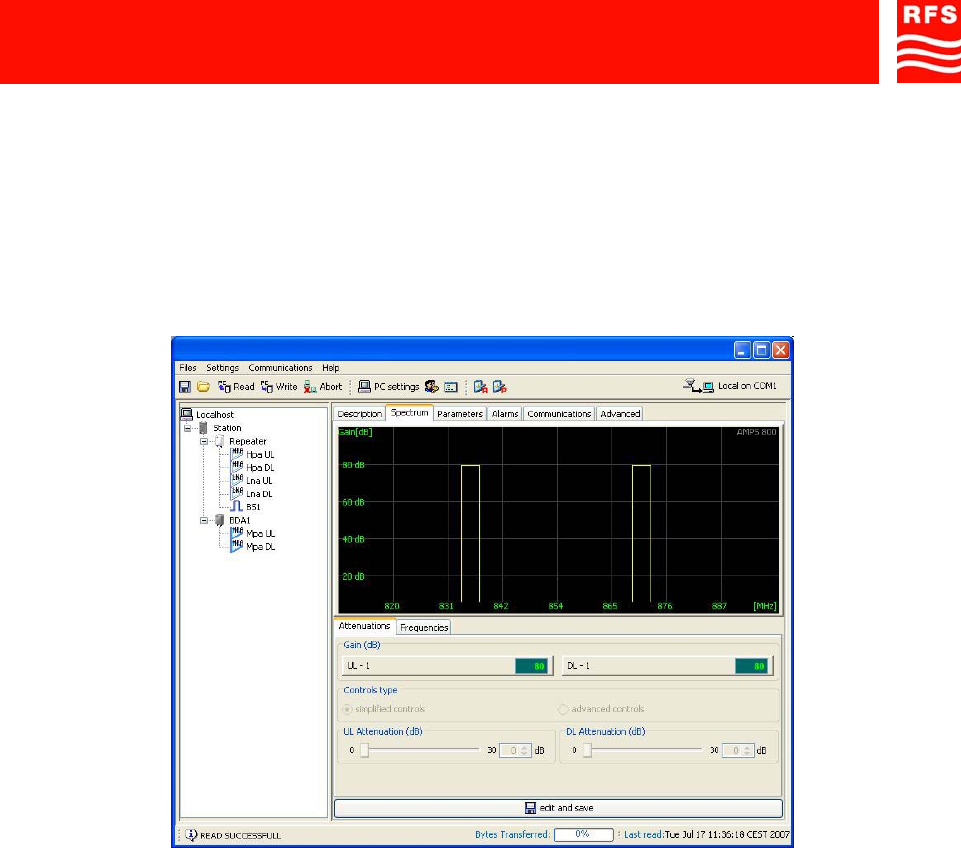
c) In the ‘Spectrum’ panel (FIGURE 11)set both ‘UL-attenuation’ and ‘DL-attenuation’ to 30 (dB) -
maximum attenuation, i.e. minimum gain.
d) Connect the cable from the donor antenna to the BTS connector on the bottom of the repeater
(ref. 52, FIGURE 3).
e) Connect the MS connector on the bottom of the repeater (ref. 56, FIGURE 3) to a spectrum
analyzer.
f) In the Spectrum panel, set the Up-link frequency center and bandwidth.
In the same panel set the repeater gain (UL-Up-link- attenuation, DL-Down-link- attenuation).
1800MHz-1900MHz Off-Air Repeaters (OR Series) Page 91 080 0701F – Rel.04
CHAPTER 4 4.12
PLEASE NOTE:
should it be necessary to set an attenuation greater than 15dB it is strongly recommended to
connect a fixed attenuator between donor antenna and the repeater BTS side port to avoid
BTS desensitisation due to excessive radiated up-link noise.
g) Check via the spectrum analyzer that the output signal level (MS side) is correct.
When the output signal level is correct, disconnect the spectrum analyzer.
FIGURE 11 – ‘SPECTRUM’ PANEL
If the repeater is used in stand-alone configuration, connect the cable from the service antenna to
the MS connector on the bottom of the repeater (ref. 56, FIGURE 3).
If the repeater is the head station of an optical fiber system, refer to the OPTICAL FIBER COVERAGE
SOLUTIONS technical handbook to install and set Master Unit and Remote Units.
If the repeater is part of a cascade system, refer to the IN-LINE AMPLIFIERS technical handbook to
install and set in-line amplifiers.
During operation the equipment can be managed, both in LOCAL and in REMOTE mode, via the software.
In REMOTE mode the equipment is managed via a modem link. On the repeater side the modem is
installed within the equipment management module.
If installing /removing the SIM card from the built-in modem is necessary, please refer to the following
procedure 6b (HOW TO INSTALL/REMOVE THE SIM CARD FROM THE BUILT-IN MODEM).
For details regarding the software, please refer to the software User’s manual.
4.3) ROUTINE MAINTENANCE
This equipment does not require any ORDINARY MAINTENANCE (or preventive maintenance) servicing.

ABBREVIATIONS AND ACRONYMS
ABBREVIATIONS AND ACRONYMS
AC Alternating Current
ALC Automatic Level Control
BDA Bi-Directional Amplifier
BTS Base Transceiver Station
DC Direct Current
DCS Digital Cellular System
EGSM Enhanced Global System for Mobile Communications
EMC Electro-Magnetic Compatibility
FET Field-Effect Transistor
GSM Global System for Mobile Communications
GSM-R GSM - Railway
HPA High Power Amplifier
IF Intermediate Frequency
IP3 Third order Intercept Point
LNA Low Noise Amplifier
MMIC Monolithic Microwave Integrated Circuit
MS Mobile Station
MTBF Mean Time Between Failures
MU Master Unit
NF Noise Figure
OMC Operation and Maintenance Center
OMT Operation and Maintenance Terminal
PC Personal Computer
PEP Peak Envelope Power
PLL Phase-Locked Loop
PSTN Public Switched Telephone Network
RAM Random Access Memory
RF Radio Frequency
RL Return Loss
RU Remote Unit
SAW Surface Acoustic Wave
SIM Subscriber Identity Module
SPV Supervision
TTL Transistor, Transistor, Logic
UMTS Universal Mobile Telecommunications System
UPS Uninterruptible Power Supply
VCO Voltage Controlled Oscillator