Radio Frequency Systems WINS-3900004 SMR800 / iDEN Pico-repeater User Manual MANUALE SERIE EMA
Radio Frequency Systems Inc SMR800 / iDEN Pico-repeater MANUALE SERIE EMA
User Manual
Radio Frequency Systems
Kabelkamp 20
30179 Hannover, Germany
Tel.: +49 511 676 2731
Fax: +49 511 676 2515
E-mail: sales.europe@rfsworld.com
FIXED BAND OFF-AIR REPEATERS
OR2-SBLP1 SERIES
TECHNICAL HANDBOOK
Doc. code 91 080 0730F - Rel. 02

91 080 0730F - OR2-SBLP1 SERIES Page 1 ENG Edit. 02
FIXED BAND OFF-AIR REPEATERS
INDEX
1. FIXED BAND OFF-AIR REPEATERS - OR2-SBLP1 SERIES....................................................................2
2. OPERATING MODE .....................................................................................................................................3
3. TECHNICAL SPECIFICATIONS ..................................................................................................................4
4. PROCEDURES FOR INSTALLATION AND POWER-UP...........................................................................5
4.1. PLANNING INSTALLATION ..................................................................................................................5
• Selecting the position for the outdoor antenna ......................................................................................5
• Isolation between the antennas .............................................................................................................6
• Repeater gain setting .............................................................................................................................6
4.2. MECHANICAL AND ELECTRICAL INSTALLATION OF THE REPEATER.................................................. 7
• Initial check.............................................................................................................................................7
• Positioning..............................................................................................................................................7
• Connections ...........................................................................................................................................8
• How to set the repeater gain..................................................................................................................8
4.3. POWER-UP...................................................................................................................................................8
5. EXTRAORDINARY MAINTENANCE – TROUBLESHOOTING ..................................................................9
ATTACHED DOCUMENTS:
- ILLUSTRATIVE DIAGRAM (ILL OR2-SBLP1 SERIES)
- ABBREVIATIONS AND ACRONYMS
- SAFETY RULES
91 080 0730F - OR2-SBLP1 SERIES Page 2 ENG Edit. 02
FIXED BAND OFF-AIR REPEATERS
1. FIXED BAND OFF-AIR REPEATERS - OR2-SBLP1 SERIES
Over the past decade, the growing diffusion of portable terminals has created the need for capillary coverage
of the territory. Telecommunications networks must permit coverage services throughout the territory in the
most extensive manner possible and, at the same time, guarantee the reliability and quality of the connection.
From this point of view, the availability and quality of the services must be also guaranteed indoors, i.e. inside
buildings.
OR2-SBLP1 SERIES has been designed specifically to improve cell coverage to indoor environments (indoor
applications): offices, stores, parking lots, malls, airports and train stations.
Each equipment in OR2-SBLP1 series is dedicated to a mobile standard (please refer to TABLE 1).
OR2-SBLP1 SERIES
REPEATER MODEL STANDARD
OR2-SBLP1-800 AMPS (800MHz) CDMA/TDMA
RFS OR2-SBLP1-900R GSM-R (900MHz)
RFS OR2-SBLP1-900 EGSM (900MHz)
RFS OR2-SBLP1-1800 DCS (1800MHz)
OR2-SBLP1-1900 PCS (1900MHz)
TABLE 1
NB:
OR2-SBLP1 Off-Air Repeaters are fixed band. It means each equipment is only able to improve the
coverage of predefined and non-modifiable band of frequencies configured during manufacturing
process. Center frequency and bandwidth (up to 4MHz for GSM-R standard, up to 25MHz for
AMPS/PCS standards and up to 15MHz for GSM/DCS standard) are factory pre-set upon customer
request.
91 080 0730F - OR2-SBLP1 SERIES Page 3 ENG Edit. 02
FIXED BAND OFF-AIR REPEATERS
2. OPERATING MODE
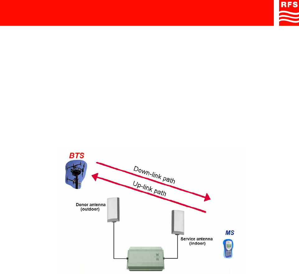
Off-Air Repeaters for indoor applications are connected, by means of coaxial cables, to two antennas. The
‘donor antenna’, an outdoor one, interfaces the equipment with the Mobile Operator’s Base Transceiver
Station (BTS). The ‘service antenna’, an indoor one, empowers the coverage of the indoor dead spot, and so it
interfaces mobile terminals.
The signal to be enhanced follows two distinct paths (FIGURE 1). The up-link path, from mobile terminals to
the BTS, and the down-link path, from the BTS to mobile terminals.
Along the down-link path, the outdoor antenna receives the signal from the BTS and then, by means of the
connecting cable, delivers it to the repeater BTS connector (ILL OR2-SBLP1 SERIES, ref. 4). The repeater
filters, amplifies and transmits the signal by feeder cable to the indoor antenna “filling” the indoor dead spot.
Indoor antenna is connected to the repeater MS connector (ref. 7, ILL OR2-SBLP1 SERIES).
Along the up-link path, the indoor antenna receives the signal from the mobile terminals (MS) and delivers it to
the repeater. The repeater filters, amplifies and transmits the signal by the outdoor antenna to Operator’s BTS.
FIGURE 1 – DOWN-LINK and UP-LINK PATHS
OR2-SBLP1 series repeaters have got built-in attenuators to allow adjustable gain. DIP-switches (ref. 5 and
ref. 6, ILL OR2-SBLP1 SERIES) are available to adjust the gain separately for up-link and down-link paths.
During installation, equipment gain can be adjusted to reduce interference towards the BTS and to avoid
problems related with the isolation between the antennas.
During operation, the equipment Automatic Level Control (ALC) protects against the emission of high
intermodulation products, both in case that the user is in the nearby vicinity of the indoor antenna (ALC up-
link) and in case of a temporary level increase of the signal coming from the donor antenna (ALC down-link).
91 080 0730F - OR2-SBLP1 SERIES Page 4 ENG Edit. 02
FIXED BAND OFF-AIR REPEATERS
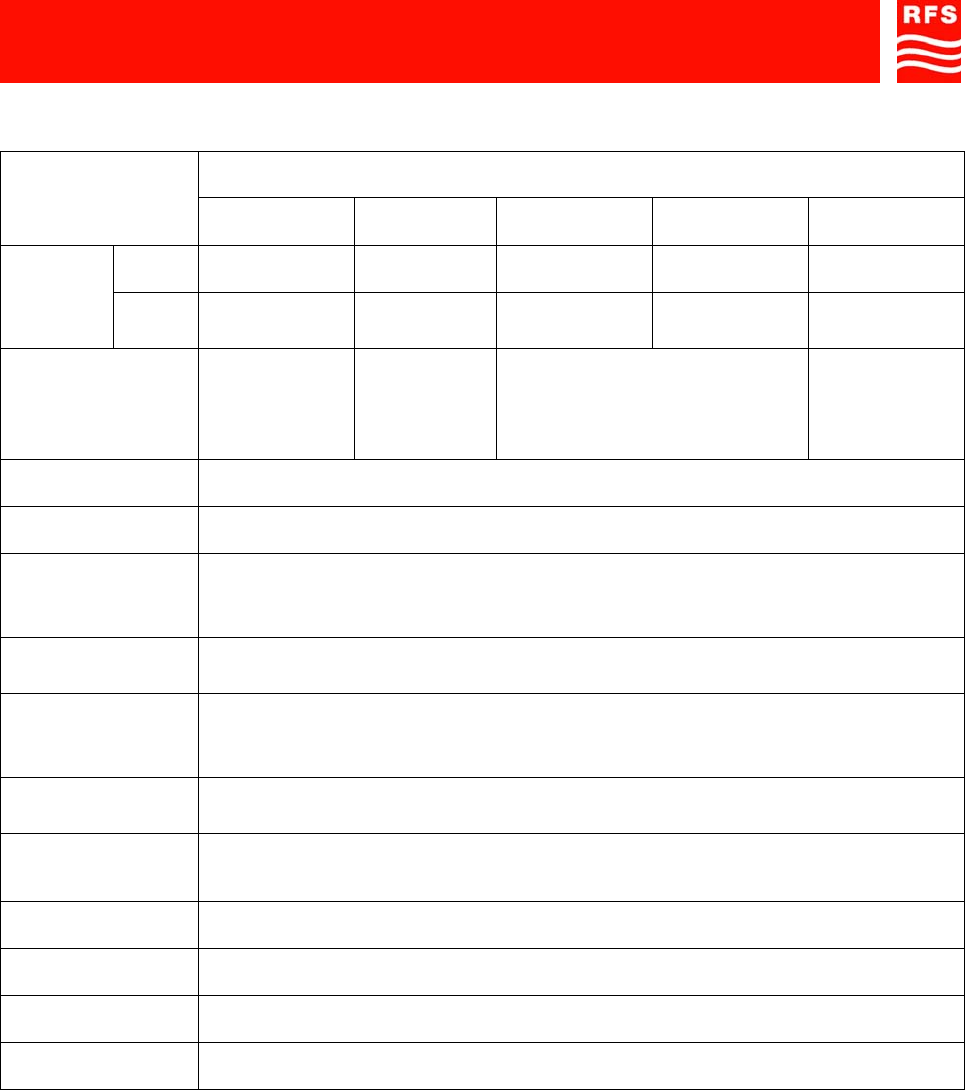
3. TECHNICAL SPECIFICATIONS
OR2-SBLP1 SERIES
REPEATER MODEL
FEATURE OR2-SBLP1-
800 OR2-SBLP1-
900R OR2-SBLP1-
900 OR2-SBLP1-
1800 OR2-SBLP1-
1900
Up-link 824-845MHz 876-880MHz 880-915MHz 1710-1785MHz 1850-1910MHz
Frequency
bands Down-
link 869-894MHz 921-925MHz 925-960MHz 1805-1880MHz 1930-1990MHz
Amplified bandwidth
Up to 25MHz
(customized
upon Customer
request)
Up to 4MHz
Up to 15MHz
(customized upon Customer
request)
Up to 25MHz
(customized
upon Customer
request)
Gain Attenuation
Range / Step 30dB Up to 60dB / 1dB step
Pass-band ripple ± 2dB
Maximum output
power (Up-link &
Down-link)
12dBm (2 carriers)
Noise figure at
maximum gain 6dB
Out of band gain
Spurious / Total
delay
Compliant to local regulations
ALC (Automatic
Level Control) range 20dB
Power supply Power
consumption
100-230Vac @ 50-60Hz / 24VA
(AC/DC converter supplied with the equipment)
RF connectors N type female
Temperature +5 up to +50°C
Dimensions (h-w-d) 220x150x40mm
Weight 1.3kg
All values are typical at 25°C unless otherwise specified.
Specifications subject to change without notice

91 080 0730F - OR2-SBLP1 SERIES Page 5 ENG Edit. 02
FIXED BAND OFF-AIR REPEATERS
4. PROCEDURES FOR INSTALLATION AND POWER-UP
• Before installing, carefully read the safety norms herewith attached.
• The equipment must be connected to ancillaries specifically designed for the standard in use
and the band to be enhanced.
• The OR2-SBLP1 SERIES has been designed for indoor use only. Changes in temperature
and humidity can influence the reliability of the equipment. The best place to install the
equipment is a tempered and well-ventilated environment.
• A correct equipment installation and setting procedure requires a good knowledge and
experience in installing telecommunication equipment. These activities should be performed
by skilled personnel only. Remember that if the equipment is not installed correctly, it may:
- cause a temporary failure in the BTS,
- be damaged by excessively high input or output signal levels.
To install the equipment we strongly suggest to follow the steps described in the paragraph below.
4.1. PLANNING INSTALLATION
• Selecting the position for the outdoor antenna
The power of the signal coming from the outdoor antenna (donor antenna) has a direct influence on the
efficiency of the indoor coverage. Therefore, it is extremely important to take care in choosing the position
for this antenna and in installing it correctly.
Before installing the outdoor antenna, it is necessary to point the donor BTS to guarantee the best
reception of signal to be enhanced. The best way to perform this activity is by connecting the donor
antenna to a spectrum analyzer (or to a field intensity level measurement instrument) to evaluate the
orientation and position of the antenna which can provide the best signal level.
It is strongly recommended to keep both antennas away from obstacles such as mountains, tall buildings
or billboards.
It is furthermore recommended to use a directional outdoor antenna with, at least, 10dBi gain and to
make sure, insofar as possible, that the antenna is pointing directly towards the BTS.
Please Note:
To obtain the best equipment performances, the outdoor signal must be stronger than -70dBm
and must not go above -20dBm. If the outdoor signal is weaker than -70dBm, it is strongly
recommended to use a high-gain directional outdoor antenna.
The ideal outdoor signal level is in the -60 to -70dBm range.

91 080 0730F - OR2-SBLP1 SERIES Page 6 ENG Edit. 02
FIXED BAND OFF-AIR REPEATERS
• Isolation between the antennas
Since the equipment is a bi-directional amplifier, the isolation between the outdoor antenna (donor) and
the indoor antenna (service) must be at least 15dB greater that the repeater gain. For example, if the
repeater gain is 60dB, the minimum isolation between both antennas must be greater than 75dB.
To guarantee the correct isolation between the antennas, it is necessary to plan for an adequate distance
between them, both horizontally and vertically. Also walls and floors can be useful to increase the
isolation between the antennas.
• Repeater gain setting
During installation, it is necessary to adjust the equipment gain. The right calculation of the gain to be set
cannot be made without an evaluation of all the variables which characterize each installation.
The minimum gain value to be set on the up-link / down-link path is determined by considering the
maximum output power and the maximum allowed input level of the equipment (-20dBm).
The balance between losses and gains for the equipment (link budget) permits adjusting the attenuation
of the two paths (down-link / up-link), in order to reduce interferences towards the BTS and to avoid
problems connected with the isolation between the antennas. Link budget also permits checking whether
or not the output signals from the equipment (towards the BTS and towards the mobile terminals) are
adequate.
PLEASE NOTE:
The repeater has been developed to operate at maximum gain. If attenuated, maximum
output power will be reduced proportionally. ALC is always enabled.
It is strongly recommended to set the repeater gain at maximum level. Attenuation should
be set only if antenna isolation is not enough (less than 75dB).
91 080 0730F - OR2-SBLP1 SERIES Page 7 ENG Edit. 02
FIXED BAND OFF-AIR REPEATERS
4.2. MECHANICAL AND ELECTRICAL INSTALLATION OF THE REPEATER
Upon completion of the planning stage, you can proceed with the installation of the antennas (indoor and
outdoor) and then with the installation and power-up of the repeater.
Please remember: the OR2-SBLP1 SERIES is designed for indoor use ONLY.
• Initial check
Check the contents of the supply in terms on its completeness and/or eventual damage undergone by the
material during transport.
The materials included in the supply are:
• OR2-SBLP1 SERIES equipment,
• External AC/DC adapter,
• Technical manual.
If there should be anything missing or damaged in the supply, you should notify the Sales Dept. of RFS, to
facilitate the reinstatement and/or repair of the equipment involved.
Before beginning installation of the equipment, make sure that ON/OFF switch, ref. 3 (ILL OR2-
SBLP1 SERIES), is in the OFF position. The green LED, ref. 2 (ILL OR2-SBLP1 SERIES), must
be turned off.
• Positioning
To avoid damages to people, it is highly recommended to install the equipment at 2.5metres high
positioning, in order to prevent electric shock caused by contact.
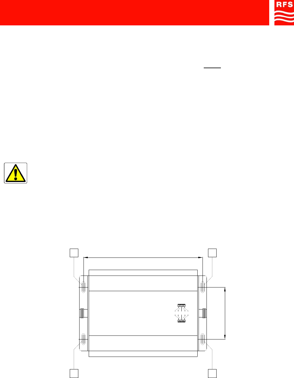
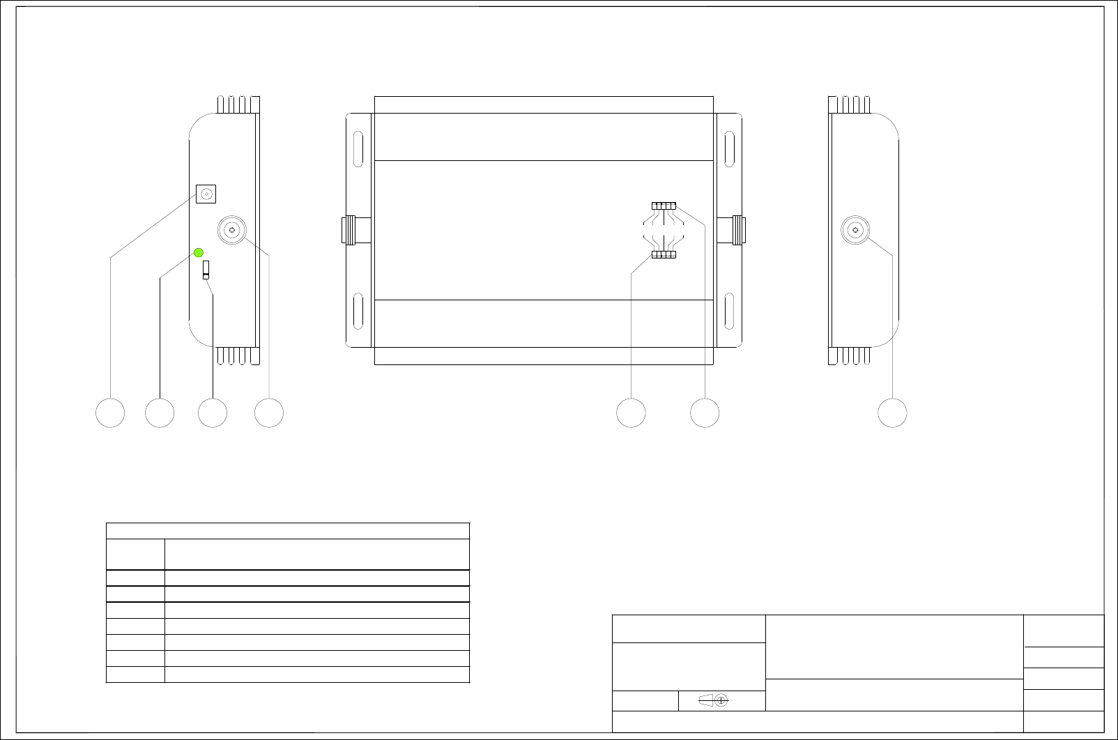
Position the OR2-SBLP1 SERIES equipment and fix its position with the four M4 bolts, which are to be
inserted in the pre-cut slots, ref. A (FIGURE 2).
Check the correct positioning of the equipment before completely tightening the bolts.
FIGURE 2 – POSITION OF THE PRE-CUT SLOTS
DOWN-LINK
UP-LINK
- 16 - 8 - 4 - 2 - 1
206 mm (8.11 in.)
90 mm (3.54 in.)
AA
AA
91 080 0730F - OR2-SBLP1 SERIES Page 8 ENG Edit. 02
FIXED BAND OFF-AIR REPEATERS
• Connections
A) Connect the cable from the outdoor antenna to connector N (f) BTS side, ref. 4 (ILL OR2-SBLP1
SERIES).
B) Connect the cable from the indoor antenna to connector N (f) MS side, ref. 7 (ILL OR2-SBLP1 SERIES).
C) Connect the power supply connector for the external AC/DC adapter (standard supply) to the power
supply socket connector of the equipment, ref. 1 (ILL OR2-SBLP1 SERIES).
D) Connect the power supply plug of the external AC/DC adapter (standard supply) to the line power source
corresponding to the specs of the equipment (i.e. 100-230V A.C.).
For the connections, it is recommended that an RF cable having characteristics similar to the RFS cable type
LCF14-50, be used.
• How to set the repeater gain
PLEASE REMEMBER:
It is strongly recommended to set the repeater gain at maximum level. Attenuation should
be set only if antenna isolation is not enough (less than 75dB).
The OR2-SBLP1 SERIES equipment comes with selectors which permit separately adjusting the gain for both
up-link and down-link paths. The maximum gain for the equipment is 60dB (typical). The attenuation of the
gain can be adjusted in the 0÷30dB range with steps of 1dB.
The variations to be made to the gain on the up-link and down-link paths are determined during link budget
calculation stage (ref. paragraph 4.1).
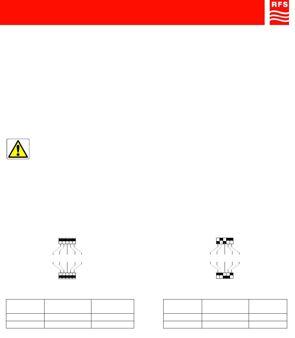
Please set the gain as shown in FIGURE 3 (Example of gain adjustment).
FIGURE 3 – EXAMPLE OF GAIN ADJUSTMENT
ON THE UP-LINK AND DOWN-LINK PATHS
4.3. POWER-UP
Once all connections have been performed and the gain has been set, turn on the equipment by moving the
switch indicated with ref. 3 (ILL OR2-SBLP1 SERIES) to the “ON” position.
Green LED, ref. 2 (ILL OR2-SBLP1 SERIES), will light up to indicate the presence of the power supply
voltage.
Also by using the mobile phone, make sure that the RF signal is available and adequate in the area of
equipment coverage.
If there should be problems, please refer to the following paragraph (troubleshooting).
DOWN-LINK
UP-LINK
- 16 - 8 - 4 - 2 - 1
ON
OFF
ON
OFF
Path Attenuation
(see Figure) Gain
Down-link 0dB 60dB
Up-link 0dB 60dB
DOWN-LINK
UP-LINK
- 16 - 8 - 4 - 2 - 1
OFF
ON
OFF
ON
Path Attenuation
(see Figure) Gain
Down-link 20dB 40dB
Up-link 25dB 35dB
91 080 0730F - OR2-SBLP1 SERIES Page 9 ENG Edit. 02
FIXED BAND OFF-AIR REPEATERS
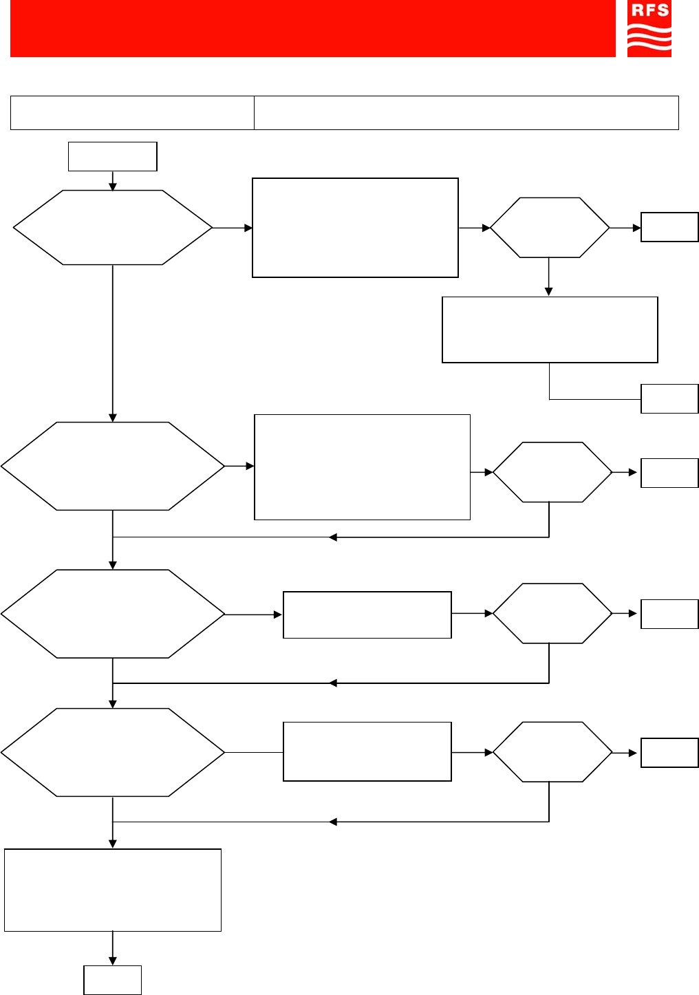
5. EXTRAORDINARY MAINTENANCE – TROUBLESHOOTING
The diagrams below describe the steps to be taken in troubleshooting, i.e. the series of operations which, in
case of equipment malfunction, permit the end-user to identify, and if possible, eliminate the causes of the
fault.
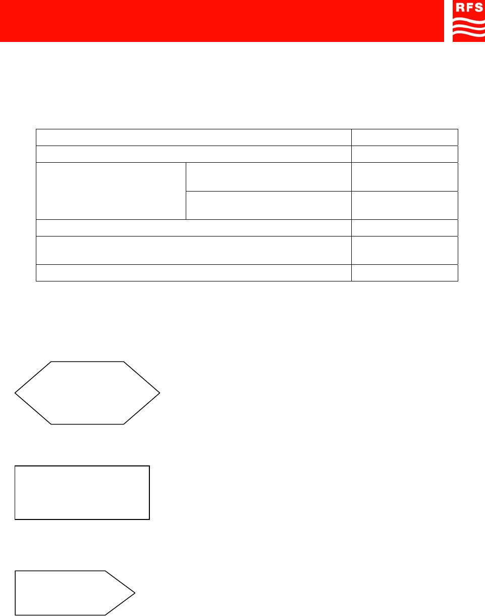
PROBLEM ENCOUNTERED STEP
GREEN LED (ref. 2, ILL OR2-SBLP1 SERIES) IS OFF 1
GREEN LED (ref. 2, ILL OR2-
SBLP1 SERIES) IS OFF 2
NO INDOOR SIGNAL GREEN LED (ref. 2, ILL OR2-
SBLP1 SERIES) IS ON 3
INDOOR SIGNAL IS TOO WEAK 4
INDOOR SIGNAL IS PRESENT, BUT YOU CANNOT MAKE A
PHONE CALL 5
INDOOR SIGNAL IS NOT STABLE 6
TABLE 2 – PROBLEM SOLVING – REFERENCE TO THE STEPS FOR TROUBLESHOOTING
The following symbols are used in the diagrams:
Interrogation box
Action box
(controls or checks)
REFERENCE TO
THE PROCEDUR
E
x Re-direction box to other procedures
“x” identifies the procedure
91 080 0730F - OR2-SBLP1 SERIES Page 10 ENG Edit. 02
FIXED BAND OFF-AIR REPEATERS
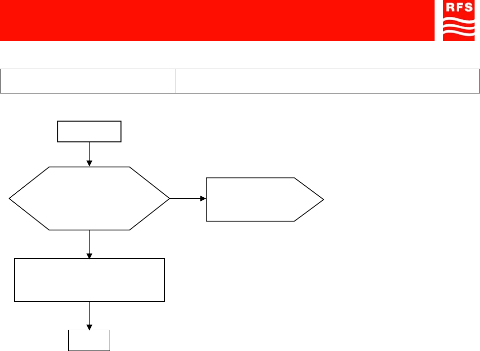
PROCEDURE 1
PROBLEM GREEN LED (ref. 2, ILL OR2-SBLP1 SERIES) IS OFF
START
no
y
es
Does the equipment
guarantee service just the
same?
The LED is broken.
The equipment can just the
same extend the signal.
END
REFERENCE TO
THE PROCEDUR
E
2
91 080 0730F - OR2-SBLP1 SERIES Page 11 ENG Edit. 02
FIXED BAND OFF-AIR REPEATERS
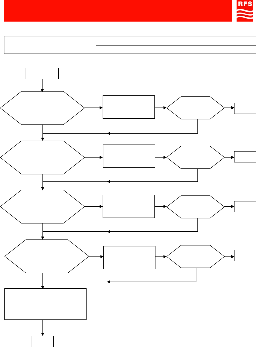
PROCEDURE 2
NO ’INDOOR’ SIGNAL
PROBLEM The GREEN LED (ref. 2, ILL OR2-SBLP1 SERIES) IS OFF
START
Is the ext. AC/DC
adapter plugged into the
line voltage?
Is the line power voltage
correct
(100-230Vac)?
no
Connect the ext.
AC/DC adapter to
the line voltage
no
Correct the line
voltage problem
Does the ext. AC/DC
adapter supply a 7Vdc
voltage?
Replace the ext.
AC/DC adapter
LED = ON? yes END
no
y
es
Is the ext. AC/DC
adapter connected to the
equipment? (connector ref.
1, ILL OR2-SBLP1
SERIES
)
Connect the ext.
AC/DC adapter to
the equipment
no
END
Equipment might be broken.
Contact RFS After-Sales
service
no
y
es
no
y
es
y
es
LED = ON? yes END
LED = ON? yes END
no
LED = ON? yes END
no
91 080 0730F - OR2-SBLP1 SERIES Page 12 ENG Edit. 02
FIXED BAND OFF-AIR REPEATERS
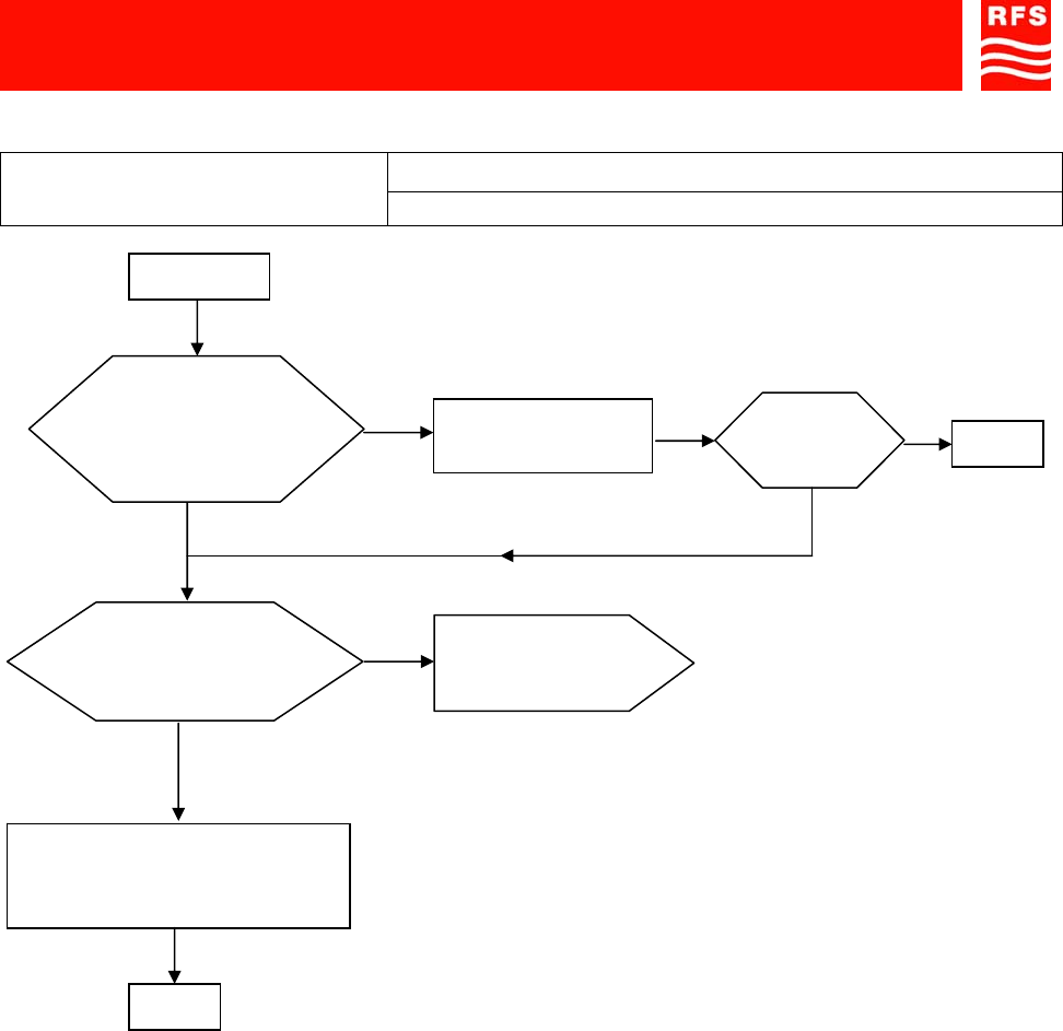
PROCEDURE 3
NO INDOOR SIGNAL
PROBLEM The GREEN LED (ref. 2, ILL OR2-SBLP1 SERIES) = ON
START
no
All connections ok
between equipment and
the antennas?
Make the
connections Signal available? END
no yes
y
es
y
es
no
Contact the phone company
(service provider) to solve the
problem.
Outdoor signal
available
(
> -70dBm
)
?
REFERENCE TO
PROCEDUR
E
4
END
91 080 0730F - OR2-SBLP1 SERIES Page 13 ENG Edit. 02
FIXED BAND OFF-AIR REPEATERS
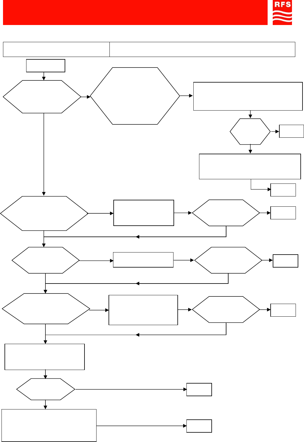
PROCEDURE 4
PROBLEM INDOOR SIGNAL is too WEAK
Outdoor signal level
adequate
(
>
-
70dBm
)?
no
y
es
START
no
Connectors between
equipment and antennas
tight?
Correctly make the
connections
y
es
Signal available? yes
END
no
Equipment might be broken.
Contact RFS After-Sales
service END
Replace the indoor antenna
with a model providing better
performance
Signal available?
Signal available?
yes
END
y
es
yes
no
Correct type
cable installed? Replace the cable
no
Equipment operating
with correct attenuation
?
Adjust the attenuations
on the up & down link
paths to optimize
equipment performance
no
Signal available?
yes
END
no
yes END
no
Signal
available? END
Contact the phone company
(service provider) to pinpoint the
best si
g
nal source.
Proper outdoor
antenna installed for
signal available (ex.
Directional antenna)?
Antenna positioned
and oriented correctl
y?
Install an antenna suited to the outdoor
signal available, or change the position
and orientation of the outdoor antenna.
yes
yes
no
END
91 080 0730F - OR2-SBLP1 SERIES Page 14 ENG Edit. 02
FIXED BAND OFF-AIR REPEATERS
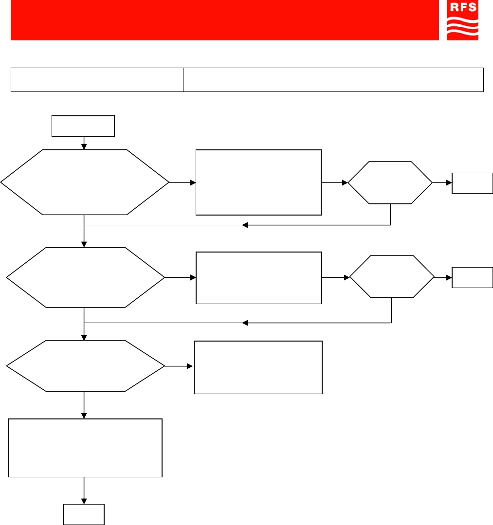
PROCEDURE 5
PROBLEM INDOOR SIGNAL IS PRESENT, BUT YOU CANNOT MAKE A
PHONE CALL
START
Isolation between outdoor
and indoor antennas = more
than 15dB greater than
repeater gain?
no Adjust the horizontal and
vertical distance between
the antennas until proper
indoor/outdoor isolation is
achieved.
y
es
Is the attenuation on the
up and down link paths
set correctly?
Phone calls
possible? END
y
es
no
no Adjust the equipment
attenuations so a to
optimize performance END
y
es
no
y
es
END
Equipment might be broken.
Contact RFS After-Sales
service
Phone calls
possible?
Can you make phone
calls outdoors? no
y
es
Contact the phone
company (service
provider) to solve the
problem.
91 080 0730F - OR2-SBLP1 SERIES Page 15 ENG Edit. 02
FIXED BAND OFF-AIR REPEATERS
PROCEDURE 6
PROBLEM INDOOR SIGNAL IS NOT STABLE
START
no
Is the outdoor signal
stable
?
y
es
Is the isolation between
outdoor and indoor
antennas?
no Adjust the horizontal and vertical
distance between the antennas to
the gain is 15dB more than the
repeater gain
Check the RF connection
cables. Are they
dama
g
ed
?
Equipment might be broken.
Contact RFS After-Sales
service
END
END
Signal stable?
no
Try to stabilize the RF signal:
Find a BTS that provides better
reception, or change the position
and orientation of the outdoor
antenna.
y
es
END
END
Signal stable?
no
Replace the damaged
cables END
Signal stable?
no
Are you sure the
connections between the
equipment and the
antennas are tight?
no Correctly make the
connections END
Signal stable?
no
y
es
Contact the phone company
(service provider) to solve the
problem.
y
es
y
es
y
es
y
es
y
es
no

ATTACHED
DOCUMENTS
DOWN-LINK
MS
UP-LINK
BTS
DC 7V
OFF/ON
- 16 - 8 - 4 - 2 - 1
3 4 76
5
21
ACCESS POINTS MAP
Rif./
Ref. DESCRIPTION
1Vdc input
2GREEN LED ON: Vdc available
3ON/OFF switch
4BTS side N (f) connector
5UP LINK path gain adjustment DIP Switches
6DOWN LINK path gain adjustment DIP Switches
7MS side N (f) connector
Copyright protection according to law
ILL OR2-SBLP1 SERIES
Scale Revisions
Title
1/1
Sheet
Date ED. 01-1
13/11/2006
Part Number
OR2-SBLP1 SERIES
ACCESS POINTS MAP Drawn by CG
AV
MN
Approved by
Checked by

SAFETY RULES Page 1 ENG
1) SAFETY RULES
1.1 Introduction
The equipment described in this technical handbook has been designed and tested in conformity o
f
international safety standards IEC215 / EN60215 and IEC950 / EN60950; the equipment has to be used
under the responsibility of specialised personnel only. In accordance with IEC215 / EN60215, adjustment,
maintenance and repair of the exposed equipment shall be carried out only by qualified personnel, who are
aware of the hazards involved. The minimum qualifications are established in the standard.
Final installation of the systems must fulfil the EMF emission levels, as requested by regulations in force
(recommendation n. 1999/519/EC).
WARNING: Installation Notes
Modular equipment, intended to be housed insidea rack cabinet, must be installed within a protected
access area only.
This area must be opportunely protected by security system that will exclude the entry, even if accidental, to
not authorized and trained personnel. Alternatively, the cabinet, in which the equipment is housed, must be
closed on all sides, to allow the access to internal parts to authorized personnel only
As far as the equipment safety devices are concerned please remind that: -periodic functional check shall be
carried out on protective devices; -functional check shall be carried out on protective devices, when they
have operated under fault conditions; -safety devices shall not be altered or disconnected except fo
r
replacement; -safety circuit shall not be modified.
For the correct and safe use of the equipment it is essential that both operation personnel and services
personnel follow generally accepted safety procedures (see IEC Publications 215: "Safety measures fo
r
radio transmitting equipment" and 61010-1: "Safety requirements for electrical equipment for measurement,
control, and laboratory use") in addition to the safety precautions specified in this technical handbook.
Specific warnings and caution statements, where applicable, can be found throughout this technical
handbook. Warning and caution statements and/or symbols are marked on the equipment where is
necessary. (see also ANNEX n°1).
1.3 Safety precautions
If it is necessary to fit an AC power supply plug to power cable, the User must observe the following colou
r
codes: LIVE terminal to BROWN lead NEUTRAL terminal to BLUE lead EARTH terminal to GREEN/YELLOW
lead The User must also ensure that the protective earth wire would be the last to break, should the cable be
subject to excessive strain.
Before power up always make sure that the equipment is connected to earth by using the equipment
grounding bolt.
When working on the equipment always make sure that the equipment is not connected to the mains
supply.
1.2 AC Power supply

SAFETY RULES Page 2 ENG
1.4 Caution and warning statements
Caution It's used to indicate the correct operation and maintenance, in order to prevent damage o
r
destruction of equipment or other property. Warning of danger Used to indicate the potential hazard that
requires correct procedures or practices in order to avoid personal injury.
1.5 Impaired safety protection
Whenever it is likely that safe operation is impaired, the apparatus must be in-operative and secured against
unintended operation. The appropriate servicing staff authority must be informed.
For instance, the safety is likely to be impaired if the equipment fails to perform the prescribed
measurements, or shows visible damages.
1.6 Electrostatic sensitive devices
In case of electrostatic sensitive devices ( for instance all ICs and many other semiconductor devices belong
to this class) it is essential to use a right protection to reduce the risk of personal injury. Careless handling,
during repair, may imply life danger. When repairing, make sure that you are connected with the same
potential as the ground of the equipment by means of the right devices, i.e. a GIRDLE (a wrist wrap with
resistance) and a WINDING CORD to be connected to the girdle and to the relevant socket placed on the
equipment.
You must also keep components and tools at this potential.
1.7 Electrolytic Capacitors
Non-solid electrolytic capacitors must not contain chemicals, which may be regarded as hazardous, if
incorrectly handled. Caution is necessary, should the outer case be fractured.
In case of electric shock it is recommended not to touch the person before breaking the circuit by means o
f
the power supply switch; should it be not possible to break the circuit power supply it would be advisable to
try to rescue the person by means of some insulating materials: e.g. a wood stick, a nylon cord or a suitable
service made of plastics, etc.
1.8 Electric shock
NEVER TOUCH ELECTROCUTED PEOPLE WITH YOUR HAND AS LONG AS THEIR BODIES ARE
SUBJECTED TO VOLTAGE, OTHERWISE YOU TOO WOULD GET ELECTOCUTED.
Call the doctor and then immediately perform the artificial respiration as described here below:

SAFETY RULES Page 3 ENG
Lay the patient on his back with his arms parallel to his body; if the patient lies on an
inclined plane, please make sure that his stomach be slightly lower than his breast.
Open the patient's mouth and check if there are foreign bodies. Kneel down near the
patient at the same level as his head's, put one of your hands under his head and the
other one under his neck. Lift the patient's neck and let his head fall backwards the
most possible.
Shift your hand from the patient's neck to his chin; put your thumb between his chin
and his mouth, your forefinger along his jawbone, keep your other fingers tight. By
doing these operations start the self-oxygenation by means of deep breathings in
standing open-mouthed. With your thumb between the patient's chin and his mouth,
keep the patient's lips closed and blow into his nasal cavities.
During these operations see if the patient's breast rises. If it is not so, his nose may be
obstructed; in this case, by levering on his chin with your hand, open the patient's
mouth, put your lips on and blow into his oral cavity. Look at the patient's breast and
see if it rises. One can use this second method instead of the first one also if the
patient's nose is not obstructed, provided that his nose be occluded by squeezing his
nostrils with your hand after shifting it from his head. The patient's head must be kept
bent backwards the most possible.
Start with ten fast and deep expirations, then go on at the rhythm of twelve/fifteen expirations per minute.
Continue as long as the patient has recovered consciousness, or a doctor has ascertained his death.
1.9 Burns
As far as burns are concerned:
• Don't try to take off clothes from the burnt parts;
• Pour some cold water on body burnt areas and ask immediately for a doctor;
• Don't apply ointments or oily tinctures.
SAFETY RULES Page 4 ENG
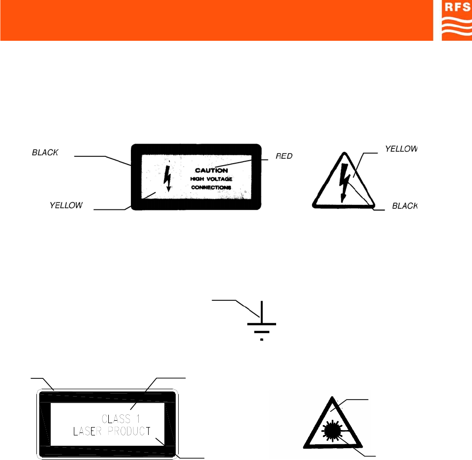
ANNEX 1
When the equipment or the modules are equipped with the labels as shown here below, it is essential to
observe the warnings contained
-LIVE VOLTAGE POINT
-PROTECTIVE EARTHING TERMINAL
BLACK
-CLASS 1 LASER PRODUCT
EXPLANATORY LABEL WARNING LABEL
(affixed to the CLASS 1 product side) (affixed to the CLASS 1 product front)
Products which are of CLASS 1 as defined in the IEC EN 60825-1, fourth edition “Safety of lase
r
products -Part 1: Equipment classification, requirements and user's guide”. Even if the product is o
f
CLASS 1, please observe the following safety procedures, prescribed in the cited norm:
• do not observe directly the laser beam,
• do not use observation optics (lens, microscopes, telescopes, etc.),
• do not expose eyes directly.
BLACK
YELLOW
BLACK
YELLOW
BLACK
SAFETY RULES Page 5 ENG
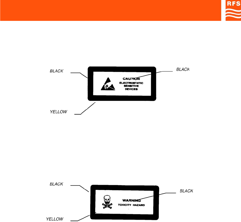
-DEVICES SENSITIVE TO THE ELECTROSTATICS
WARNING: Please observe the due precautions in handling devices which are sensitive to the
electrostatics.
-NON-SOLID ELECTROLYPTIC CAPACITORS MAY CONTAIN CHEMICALS TO BE REGARDED AS
HAZARDOUS, IF INCORRECTLY HANDLED.
WARNING
THE MAXIMUM CAUTION IS REQUIRED IF THE OUTER CASE IS FRACTURED

STANDARDS Page 1 ENG
2) STANDARDS
2.1. MANUFACTURE LABELS
2.1.1 BAR CODE LABEL
Label fields (ref. Fig.1):
a) Serial number: this field contains the serial number (made up of a 7-digit sequential group) of the
module or equipment.
b) F (final test tracing out): this field contains an F letter that has been barred to certify that the item has
been successfully tested in the factory Final Test Dept.
c) Customer order reference.
d) Equipment acronym or manufacture part number.
e) ICS (Item Change Status): this field contains the item ICS, made up of 2 digits, starting from 01, of the
manufacture part number or equipment.
Fig.2 shows an example of bar code label applied:
On equipment other labels may be present, as integration of what reported in bar code label (fig.1);
see following pages.
Fig. 1
Fig. 2
STANDARDS Page 2 ENG
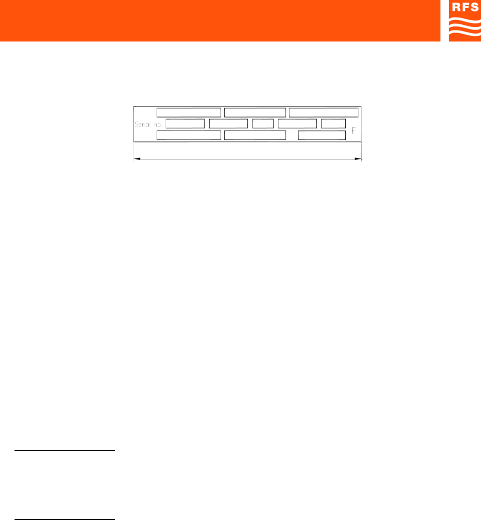
2.1.2 MANUFACTURE LABELS FOR RACK CABINETS AND EQUIPMENT
Label fields (ref. Fig.3):
(1) SYSTEM (it will be filled in only if the rack cabinet or the equipment belong to a system):
this field contains the system acronym.
(2) EQUIPMENT:
This field contains the acronym of the rack cabinet or equipment.
(3) MANUFACTURE PART NUMBER:
This field contains the manufacture part number either of the rack cabinet or the equipment.
(4) SERIAL NUMBER:
This field contains the serial number (made up of a 5-digit sequential group) of the rack cabinet or
equipment.
The serial number of each item comes from the manufacture orders print-out (for domestic and foreign
markets).
(5) QIF (Quality Identification Factor):
FACTORY USE ONLY
(6) ICS (Item Change Status):
This field contains the item ICS, made up of 2 digits, of the rack cabinet or equipment.
(7) ORIGIN CODE:
FACTORY USE ONLY
(8) MANUFACTURE YEAR AND WEEK:
This field contains the manufacture year and week of the rack cabinet or equipment (4 digits, the first two
of which indicate the year, while the last two digits indicate the relevant week) e.g. 9515: 15th week of
1995.
Fig. 3
90mm
(9)
(4)
(1)
(7)
(10)
(2)
(5) (6)
(11)
(8)
(3)
STANDARDS Page 3 ENG
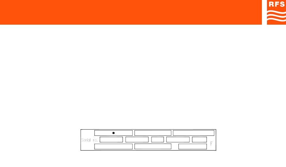
(9) SUPPLY VOLTAGE (from MAINS and/or from DC SOURCE)
(10) ABSORBED CURRENT
(11) MAINS FREQUENCY
F (final test tracing out):
This field contains an F letter that has been barred to certify that the item has been successfully tested in
the factory Final Test Dept.
Fig.4 shows an example of manufacture label as applied to a RACK CABINET or to an EQUIPMENT.
(•) System acronym (if any)
For instance, you will find the manufacture label placed:
- on the upper left corner of the rack cabinet frame;
- on the rear side (or on the external right side) of the equipment rack.
230Vac/48Vdc
58822 A0122
0.5Aac/0.89Adc
00021 01
50/60 Hz
9515
Fig. 4
STANDARDS Page 4 ENG
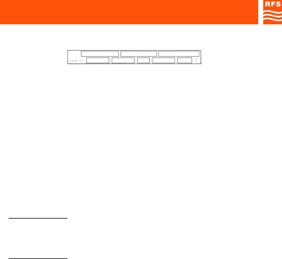
2.1.3 MANUFACTURE LABELS FOR RACKS AND PLUG-IN, OR WIRING TYPE, MODULES
Label fields (ref. Fig.5):
(1) SYSTEM (it will be filled in only if the rack or the module to be label belong to a system):
this field contains the system acronym.
(2) EQUIPMENT:
This field contains the acronym of the rack, or module.
(3) MANUFACTURE PART NUMBER:
This field contains the manufacture part number of the rack or module.
(4) SERIAL NUMBER:
This field contains the serial number (made up of a 5-digit sequential group) of the rack or module.
The serial number of each item comes from the manufacture orders print-out (for domestic and foreign
markets).
(5) QIF (Quality Identification Factor)
FACTORY USE ONLY
(6) ICS (Item Change Status):
This field contains the item ICS, made up of 2 digits, of the rack or module.
(7) ORIGIN CODE:
FACTORY USE ONLY
(8) MANUFACTURE YEAR AND WEEK:
This field contains the manufacture year and week of the rack or module (4 digits, the first two of which
indicate the year, while the last two digits indicate the relevant week) e.g. 9515: 15th week of 1995.
Fig. 5
(4)
(1)
(7)
(2)
(5) (6) (8)
(3)
STANDARDS Page 5 ENG
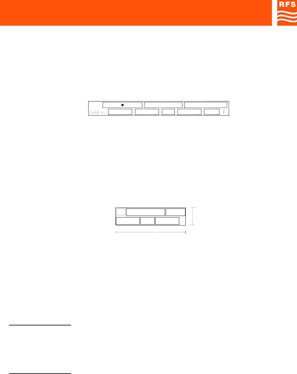
F (final test tracing out):
This field contains an F letter that has been barred to certify that the item (rack or module) has been
successfully tested in the factory Final Test Dept.
Fig.6 shows an example of manufacture label as applied to a RACK or PLUG-IN, or WIRING TYPE
MODULES.
(•) System acronym (if any)
For instance, you will find the manufacture label placed:
- on the topside of the plug-in module, right or left;
- on the topside of the wiring-type module.
2.1.4 SUB-MODULES MANUFACTURE LABEL
Label fields (ref. Fig.7):
(3) MANUFACTURE PART NUMBER:
This field contains the sub-module manufacture part number.
(5) QIF (Quality Identification Factor)
FACTORY USE ONLY
(6) ICS (Item Change Status):
This field contains the item ICS, made up of 2 digits, of the sub-module.
(7) ORIGIN CODE:
FACTORY USE ONLY
Fig. 6
58822 A012200021 01 9515
Fig. 7
F

STANDARDS Page 6 ENG
(8) MANUFACTURE YEAR AND WEEK:
This field contains the manufacture year and week of the submodule (4 digits, the first two of which
indicate the year, while the last two digits indicate the relevant week) e.g. 9542: 42nd week of 1995.
F (final test tracing out):
This field contains an F letter that has been barred to certify that the item (sub-module) has been
successfully tested in the factory Final Test Dept.
Fig. 8 shows an example of manufacture label as applied to a SUB-MODULE.
You will find the manufacture label placed on the sub-module top, left, or right side.
Fig. 8
F
00081
.01 B0111
STANDARDS Page 7 ENG
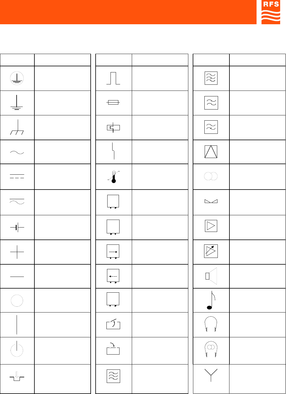
2.2) SYMBOLS
EQUIPMENT FRONT SYMBOLS
SYMBOLS DESCRIPTION SYMBOLS DESCRIPTION SYMBOLS DESCRIPTION
Earth connection Impulsive command Band-stop filter
Ground Fuse Low-pass filter
Chassis ground Thermal breaker High-pass filter
AC Failure Modulator,
demodulator
DC Overtemperature Stereo
Pulse current Output monitoring
signal Balance
Battery / accumulator Input monitoring
signal Amplifier
Positive connector
P
Direct power
monitoring socket Adjustable gain
amplifier
Negative connector
P
Reflected power
monitoring socket Loudspeaker
connection
OFF
L.O.
Local oscillator
monitoring socket Audio connection
ON Gating as opening
criterion Headphone
connection
STAND-BY Gating as closing
criterion Stereo headphone
ON push-button Channel / band filter Star connection
STANDARDS Page 8 ENG
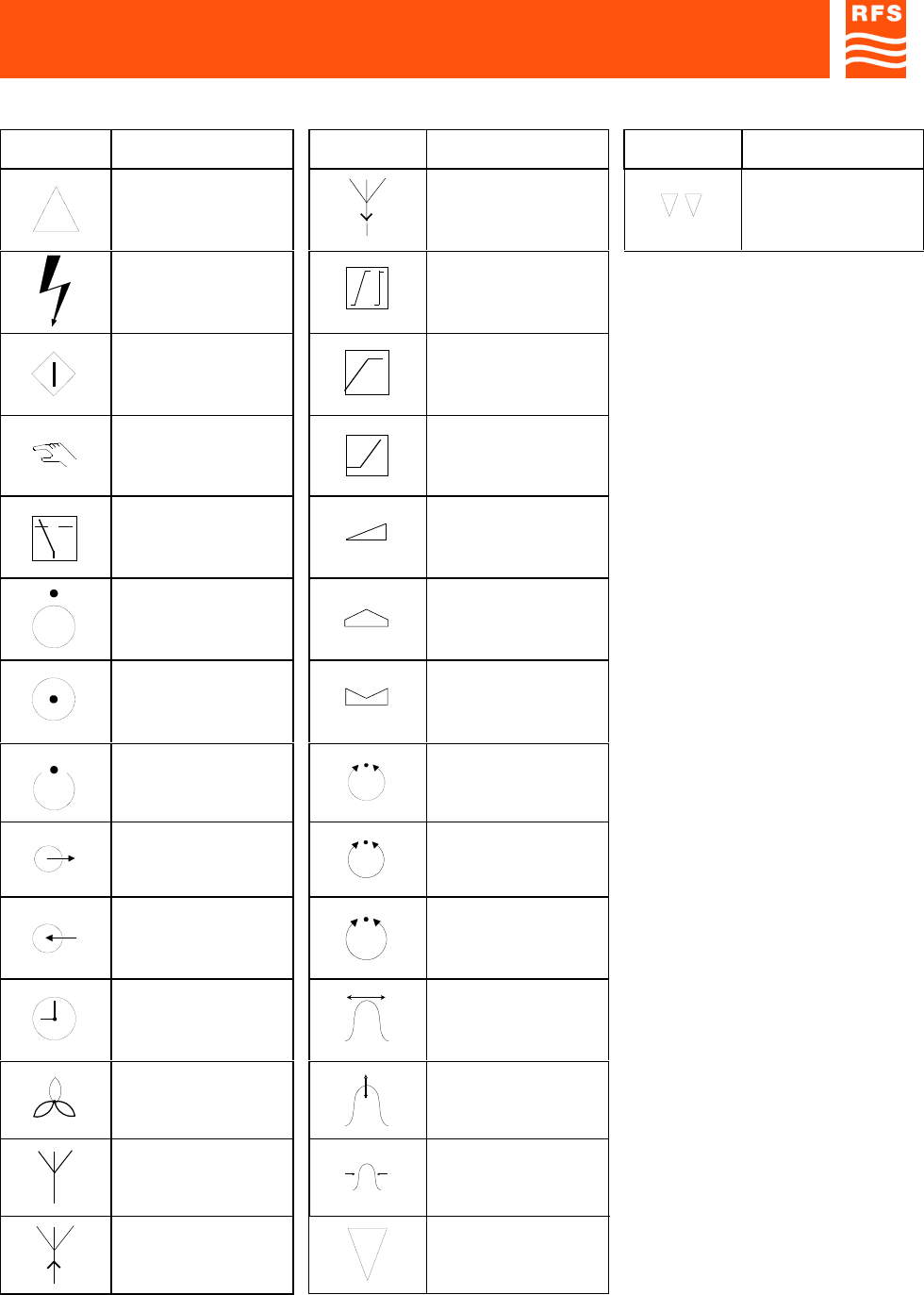
EQUIPMENT FRONT SYMBOLS
SYMBOLS DESCRIPTION SYMBOLS DESCRIPTION SYMBOLS DESCRIPTION
Delta connection Receiving antenna Dual sound
High voltage Linearization
Start push-button Limiter upper
threshold
Local, manual
command Limiter lower
threshold
Automatic Adjusting
OFF / inhibited
(function) Max adjusting
ON / active
(function) Min adjusting
Stand-by
(function) Adjusting
Output connector
f
Frequency adjusting
Input connector
5MHz
Xtal adjusting
Clock display
(operation time
counter)
Freq. tuning
Fan, blower Amplitude tuning
Antenna Band tuning
Transmission antenna Mono
STANDARDS Page 9 ENG
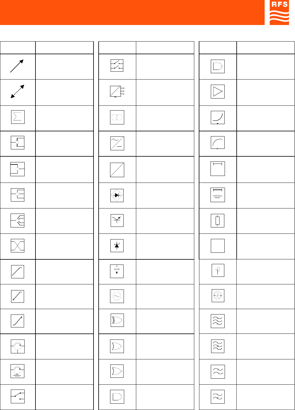
BLOCK DIAGRAM SYMBOLS
SYMBOLS DESCRIPTION SYMBOLS DESCRIPTION SYMBOLS DESCRIPTION
Linear variability 2-way switch NAND general symbol
Automatic adjustment Voltage control
electromagnetic relay NOT general symbol
Combiner general
sign Transformer Preemphasis
2-way power divider Rectifier general
symbol Deenphasis
2-way power
combiner
=
=
DC/DC converter Delay line general
symbol
3-way power divider Bridge rectifier Coaxial type time
delay limiter
4-way power divider
REG
Voltage regulator Resistive attenuator
3dB Hybrid Zener regulator
dB
Pad
LIM.
WHITE
White limiter
BIAS
Constant current bias
device Fixed phase shifter
Positive peak clipper Sinusoidal oscillator
THERMAL
SWITCH
Thermal switch
Negative peak clipper Ex-OR Band-pass filter
Circulator OR general symbol Band-stop filter
Isolator NOR general symbol Low-pass filter
Switch AND general symbol High-pass filter
STANDARDS Page 10 ENG
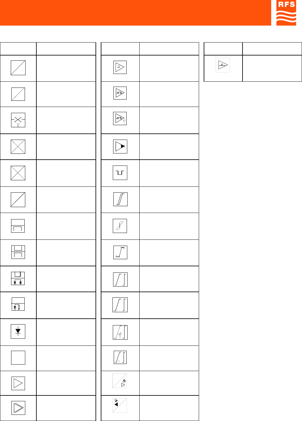
BLOCK DIAGRAM SYMBOLS
SYMBOLS DESCRIPTION SYMBOLS DESCRIPTION SYMBOLS DESCRIPTION
f
f/n
Divider by n DC amplifier Optical amplifier
f
f/n
Multiplier by n Differential
comparator
Mixer general symbol Phase comparator
RF
FI
OL
Up-converter from IF
to RF Detector amplifier
RF FI
OL
Down-converter from
RF to IF
CLAMP
P. SYNC Lamped to the
syncrhronizing signal
peak
f
V
Voltage / frequency
converter Schmitt’s trigger
Directional coupler Amplitude linearity
precorrector
Double directional
coupler Amplitude limiter
without distortion
Directional coupler
with double detector Equalizer general sign
Detector
A
Amplitude equalizer
Peak detector Phase equalizer
XX
3To rise to cubical
power
T
Propagation time
equalizer
Amplifier general
symbol
RF
Laser diode electrical-
optical transmitter
Multistage amplifier
RF
Optical-electrical
receiver

ABBREVIATIONS AND ACRONYMS
ABBREVIATIONS AND ACRONYMS
AC Alternating Current
ALC Automatic Level Control
BDA Bi-Directional Amplifier
BTS Base Transceiver Station
DC Direct Current
DCS Digital Cellular System
EGSM Enhanced Global System for Mobile Communications
EMC Electro-Magnetic Compatibility
FET Field-Effect Transistor
GSM Global System for Mobile Communications
GSM-R GSM - Railway
HPA High Power Amplifier
IF Intermediate Frequency
IP3 Third order Intercept Point
LNA Low Noise Amplifier
MMIC Monolithic Microwave Integrated Circuit
MS Mobile Station
MTBF Mean Time Between Failures
MU Master Unit
NF Noise Figure
OMC Operation and Maintenance Center
OMT Operation and Maintenance Terminal
PC Personal Computer
PEP Peak Envelope Power
PLL Phase-Locked Loop
PSTN Public Switched Telephone Network
RAM Random Access Memory
RF Radio Frequency
RL Return Loss
RU Remote Unit
SAW Surface Acoustic Wave
SIM Subscriber Identity Module
SPV Supervision
TTL Transistor, Transistor, Logic
UMTS Universal Mobile Telecommunications System
UPS Uninterruptible Power Supply
VCO Voltage Controlled Oscillator