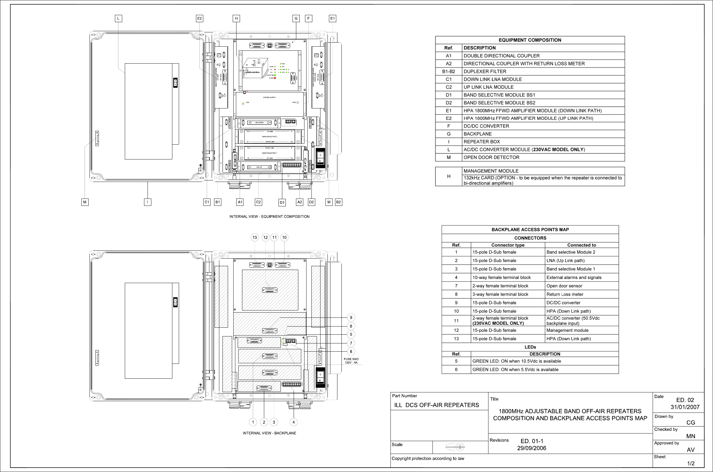
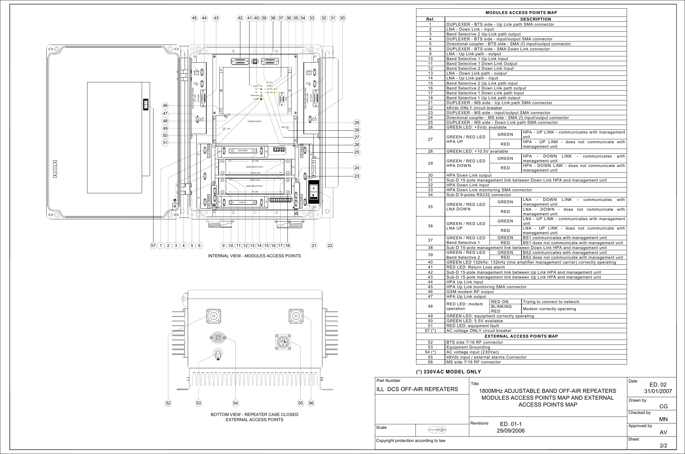
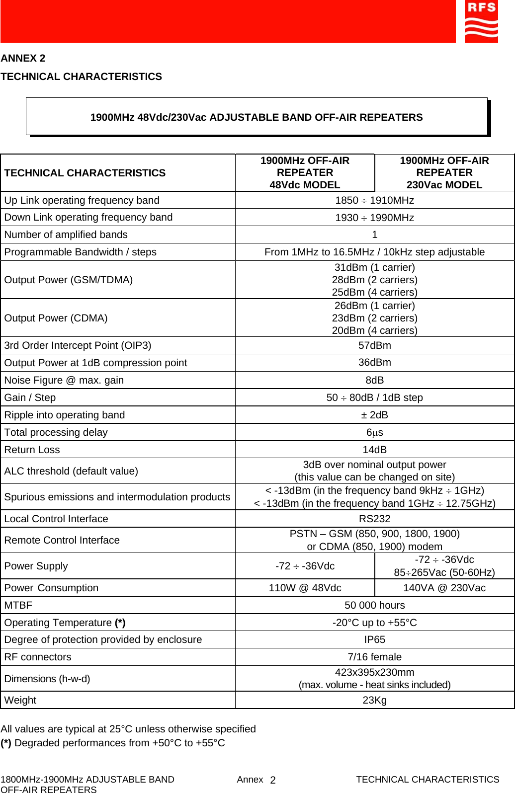
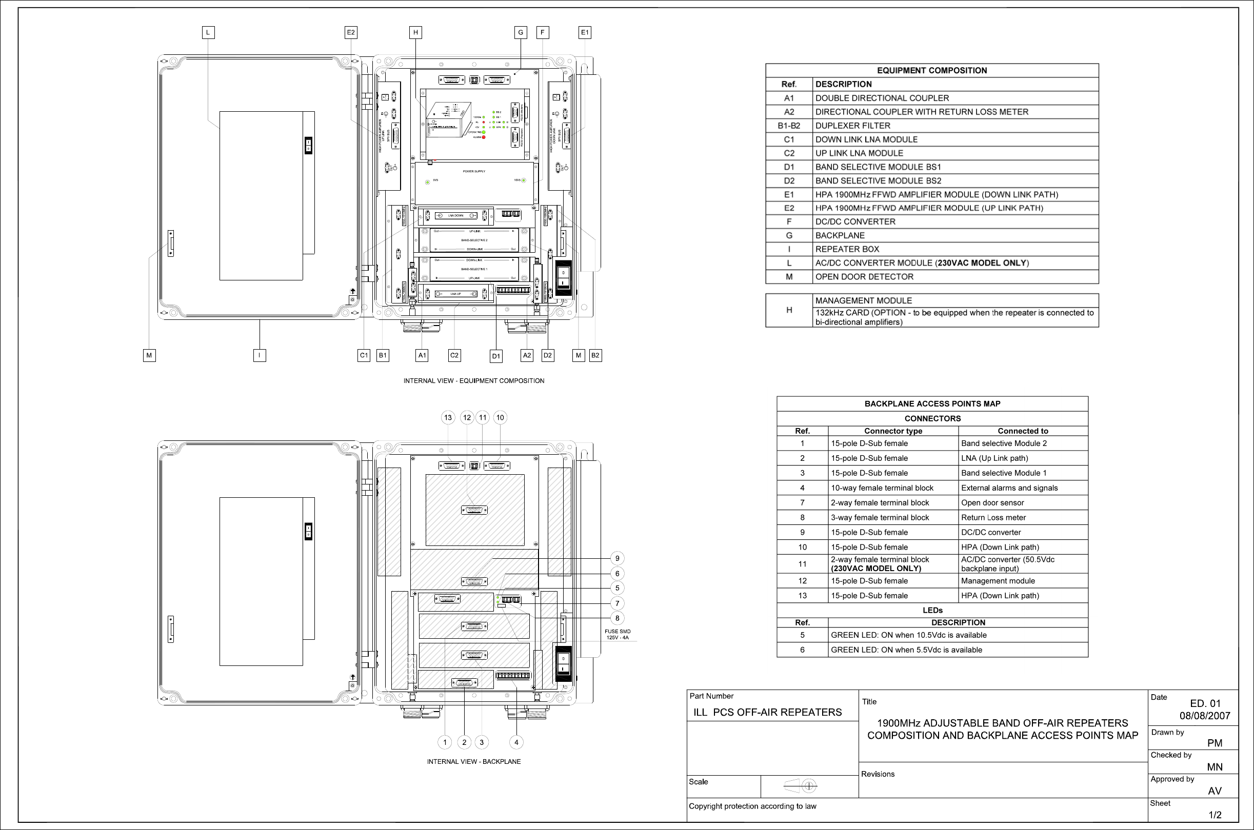
Radio Frequency Systems WINS-3900003 PCS 1900 Off-air repeater User Manual

Radio Frequency Systems Inc PCS 1900 Off-air repeater

User Manual

    Radio Frequency Systems Kabelkamp 20 30179 Hannover, Germany Tel.: +49 511 676 2731 Fax: +49 511 676 2515 E-mail: sales.europe@rfsworld.com 1800MHz - 1900MHz ADJUSTABLE BANDWIDTH OFF-AIR REPEATERS OR1-SBHP1-1800 OR2-SBHP1-1800 OR1-SBHP1-1900 OR2-SBHP1-1900  TECHNICAL HANDBOOK Doc. code 91 080 0701F - Rel. 04
    1800MHz – 1900MHZ Off-Air Repeaters (OR Series)  Page   91 080 0701F – Rel.04 INDEX  1 INDEX   1) SAFETY RULES ................................................................................................................................... 1  2) STANDARDS........................................................................................................................................ 2   2.1) MANUFACTURE LABELS 2.2) SYMBOLS  3) GENERAL DESCRIPTION ................................................................................................................... 3 3.1) EXAMPLE: USE IN TUNNELS 3.2) OPERATING PRINCIPLE - 1800MHz - 1900MHz ADJUSTABLE BAND OFF-AIR REPEATERS 3.3) ATTACHED DOCUMENTS  4) INSTALLATION AND POWER-UP PROCEDURES............................................................................ 4 4.1) INSTALLATION A - INITIAL CHECK B - POSITIONING THE REPEATER C - POWER SUPPLY SOURCE CONNECTIONS AND ALARMS CONNECTIONS D.C. POWERED EQUIPMENT AC POWERED EQUIPMENT (ALTERNATE CURRENT) 4.2) POWER-UP 4.3) ROUTINE MAINTENANCE
1
 1) SAFETY RULES     1.1 Introduction  The equipment described in this technical handbook has been designed and tested in conformity of international safety standards IEC215 / EN60215 and IEC950 / EN60950; the equipment has to be used under the responsibility of specialised personnel only. In accordance with IEC215 / EN60215, adjustment, maintenance and repair of the exposed equipment shall be carried out only by qualified personnel, who are aware of the hazards involved. The minimum qualifications are established in the standard. Final installation of the systems must fulfil the EMF emission levels, as requested by regulations in force (recommendation n. 1999/519/EC). WARNING: Installation Notes Modular equipment, intended to be housed insidea rack cabinet, must be installed within a protected access area only.   This area must be opportunely protected by security system that will exclude the entry, even if accidental, to not authorized and trained personnel. Alternatively, the cabinet, in which the equipment is housed, must be closed on all sides, to allow the access to internal parts to authorized personnel only   When working on the equipment always make sure that the equipment is not connected to the mains supply.  1.2 AC Power supply  Before power up always make sure that the equipment is connected to earth by using the equipment grounding bolt.  If it is necessary to fit an AC power supply plug to power cable, the User must observe the following colour codes: LIVE terminal to BROWN lead NEUTRAL terminal to BLUE lead EARTH terminal to GREEN/YELLOW lead The User must also ensure that the protective earth wire would be the last to break, should the cable be subject to excessive strain.  1.3 Safety precautions  For the correct and safe use of the equipment it is essential that both operation personnel and services personnel follow generally accepted safety procedures (see IEC Publications 215: "Safety measures for radio transmitting equipment" and 61010-1: "Safety requirements for electrical equipment for measurement, control, and laboratory use") in addition to the safety precautions specified in this technical handbook. Specific warnings and caution statements, where applicable, can be found throughout this technical handbook. Warning and caution statements and/or symbols are marked on the equipment where is necessary. (see also ANNEX n°1).  As far as the equipment safety devices are concerned please remind that: -periodic functional check shall be carried out on protective devices; -functional check shall be carried out on protective devices, when they have operated under fault conditions; -safety devices shall not be altered or disconnected except for replacement; -safety circuit shall not be modified.   SAFETI RULES    ENG
 1.4 Caution and warning statements   Caution It's used to indicate the correct operation and maintenance, in order to prevent damage or destruction of equipment or other property. Warning of danger Used to indicate the potential hazard that requires correct procedures or practices in order to avoid personal injury.      1.5 Impaired safety protection  Whenever it is likely that safe operation is impaired, the apparatus must be in-operative and secured against unintended operation. The appropriate servicing staff authority must be informed.  For instance, the safety is likely to be impaired if the equipment fails to perform the prescribed measurements, or shows visible damages.  1.6 Electrostatic sensitive devices  In case of electrostatic sensitive devices ( for instance all ICs and many other semiconductor devices belong to this class) it is essential to use a right protection to reduce the risk of personal injury. Careless handling, during repair, may imply life danger. When repairing, make sure that you are connected with the same potential as the ground of the equipment by means of the right devices, i.e. a GIRDLE (a wrist wrap with resistance) and a WINDING CORD to be connected to the girdle and to the relevant socket placed on the equipment.  You must also keep components and tools at this potential.  1.7 Electrolytic Capacitors  Non-solid electrolytic capacitors must not contain chemicals, which may be regarded as hazardous, if incorrectly handled. Caution is necessary, should the outer case be fractured.  1.8 Electric shock  In case of electric shock it is recommended not to touch the person before breaking the circuit by means of the power supply switch; should it be not possible to break the circuit power supply it would be advisable to try to rescue the person by means of some insulating materials: e.g. a wood stick, a nylon cord or a suitable service made of plastics, etc.  NEVER TOUCH ELECTROCUTED PEOPLE WITH YOUR HAND AS LONG AS THEIR BODIES ARE SUBJECTED TO VOLTAGE, OTHERWISE YOU TOO WOULD GET ELECTOCUTED.  Call the doctor and then immediately perform the artificial respiration as described here below:   SAFETI RULES    ENG
 Lay the patient on his back with his arms parallel to his body; if the patient lies on an inclined plane, please make sure that his stomach be slightly lower than his breast. Open the patient's mouth and check if there are foreign bodies. Kneel down near the patient at the same level as his head's, put one of your hands under his head and the other one under his neck. Lift the patient's neck and let his head fall backwards the most possible.  Shift your hand from the patient's neck to his chin; put your thumb between his chin and his mouth, your forefinger along his jawbone, keep your other fingers tight. By doing these operations start the self-oxygenation by means of deep breathings in standing open-mouthed. With your thumb between the patient's chin and his mouth, keep the patient's lips closed and blow into his nasal cavities.  During these operations see if the patient's breast rises. If it is not so, his nose may be obstructed; in this case, by levering on his chin with your hand, open the patient's mouth, put your lips on and blow into his oral cavity. Look at the patient's breast and see if it rises. One can use this second method instead of the first one also if the patient's nose is not obstructed, provided that his nose be occluded by squeezing his nostrils with your hand after shifting it from his head. The patient's head must be kept bent backwards the most possible.   Start with ten fast and deep expirations, then go on at the rhythm of twelve/fifteen expirations per minute. Continue as long as the patient has recovered consciousness, or a doctor has ascertained his death.   1.9 Burns  As far as burns are concerned: Don't try to take off clothes from the burnt parts; Pour some cold water on body burnt areas and ask immediately for a doctor; Don't apply ointments or oily tinctures.   SAFETI RULES    ENG
 ANNEX 1   When the equipment or the modules are equipped with the labels as shown here below, it is essential to observe the warnings contained   -LIVE VOLTAGE POINT   -PROTECTIVE EARTHING TERMINAL  BLACK   -CLASS 1 LASER PRODUCT   BLABLACK   CK YELLOW  YELLOW  BLACK  EXPLANATORY LABEL (affixed to the WARNING LABEL (affixed to the CLASS 1 product side) CLASS 1 product front)  Products which are of CLASS 1 as defined in the IEC EN 60825-1, fourth edition “Safety of laser products -Part 1: Equipment classification, requirements and user's guide”. Even if the product is of CLASS 1, please observe the following safety procedures, prescribed in the cited norm:  •  do not observe directly the laser beam,  •  do not use observation optics (lens, microscopes, telescopes, etc.),  •  do not expose eyes directly.   SAFETI RULES    ENG
 -DEVICES SENSITIVE TO THE ELECTROSTATICS  WARNING: Please observe the due precautions in handling devices which are sensitive to the electrostatics.   -NON-SOLID ELECTROLYPTIC CAPACITORS MAY CONTAIN CHEMICALS TO BE REGARDED AS HAZARDOUS, IF INCORRECTLY HANDLED. WARNING  THE MAXIMUM CAUTION IS REQUIRED IF THE OUTER CASE IS FRACTURED     SAFETI RULES    ENG
2
STANDARDS Page 12) STANDARDS2.1. MANUFACTURE LABELS2.1.1 BAR CODE LABELLabel fields (ref. Fig.1):a) Serial  number: this  field  contains  the  serial  number  (made  up  of  a  7-digit  sequential  group)  of  themodule or equipment.b) F (final test tracing out): this field contains an F letter that has been barred to certify that the item hasbeen successfully tested in the factory Final Test Dept.c) Customer order reference.d) Equipment acronym or manufacture part number.e) ICS (Item Change Status): this field contains the item ICS, made up of 2 digits, starting from 01, of themanufacture part number or equipment.Fig.2 shows an example of bar code label applied:On equipment other labels may be present, as integration of what reported in bar code label (fig.1);see following pages.Fig. 1Fig. 2
STANDARDS Page 32.1.2 MANUFACTURE LABELS FOR RACK CABINETS AND EQUIPMENTLabel fields (ref. Fig.3):(1) SYSTEM (it will be filled in only if the rack cabinet or the equipment belong to a system):this field contains the system acronym.(2) EQUIPMENT:This field contains the acronym of the rack cabinet or equipment.(3) MANUFACTURE PART NUMBER:This field contains the manufacture part number either of the rack cabinet or the equipment.(4) SERIAL NUMBER:This  field  contains  the  serial  number  (made  up  of  a  5-digit  sequential  group)  of  the  rack  cabinet  orequipment.The serial number of each item comes from the manufacture orders print-out (for domestic and foreignmarkets).  (5) QIF (Quality Identification Factor):FACTORY USE ONLY(6) ICS (Item Change Status):This field contains the item ICS, made up of 2 digits, of the rack cabinet or equipment.(7) ORIGIN CODE:FACTORY USE ONLY(8) MANUFACTURE YEAR AND WEEK:This field contains the manufacture year and week of the rack cabinet or equipment (4 digits, the first twoof which indicate the year, while the last two digits indicate the relevant week) e.g. 9515: 15th week of1995.Fig. 390mm(9)(4)(1)(7)(10)(2)(5) (6)(11)(8)(3)
STANDARDS Page 4(9) SUPPLY VOLTAGE (from MAINS and/or from DC SOURCE)(10) ABSORBED CURRENT(11) MAINS FREQUENCYF (final test tracing out):This field contains an F letter that has been barred to certify that the item has been successfully tested inthe factory Final Test Dept.Fig.4 shows an example of manufacture label as applied to a RACK CABINET or to an EQUIPMENT.(•) System acronym (if any)For instance, you will find the manufacture label placed:- on the upper left corner of the rack cabinet frame;- on the rear side (or on the external right side) of the equipment rack.230Vac/48Vdc58822 A01220.5Aac/0.89Adc00021 0150/60 Hz9515Fig. 4
STANDARDS Page 52.1.3 MANUFACTURE LABELS FOR RACKS AND PLUG-IN, OR WIRING TYPE, MODULESLabel fields (ref. Fig.5):(1) SYSTEM (it will be filled in only if the rack or the module to be label belong to a system):this field contains the system acronym.(2) EQUIPMENT:This field contains the acronym of the rack, or module. (3) MANUFACTURE PART NUMBER:This field contains the manufacture part number of the rack or module.(4) SERIAL NUMBER:This field contains the serial number (made up of a 5-digit sequential group) of the rack or module.The serial number of each item comes from the manufacture orders print-out (for domestic and foreignmarkets).(5) QIF (Quality Identification Factor)FACTORY USE ONLY(6) ICS (Item Change Status):This field contains the item ICS, made up of 2 digits, of the rack or module.(7) ORIGIN CODE:FACTORY USE ONLY(8) MANUFACTURE YEAR AND WEEK:This field contains the manufacture year and week of the rack or module (4 digits, the first two of whichindicate the year, while the last two digits indicate the relevant week) e.g. 9515: 15th week of 1995.Fig. 5(4)(1)(7)(2)(5) (6) (8)(3)
STANDARDS Page 6F (final test tracing out):This field contains  an  F letter  that has  been barred to  certify that  the item (rack  or module)  has  beensuccessfully tested in the factory Final Test Dept.Fig.6  shows  an  example  of  manufacture  label  as  applied  to  a  RACK  or  PLUG-IN,  or  WIRING  TYPEMODULES.(•) System acronym (if any)For instance, you will find the manufacture label placed:- on the topside of the plug-in module, right or left;- on the topside of the wiring-type module.2.1.4 SUB-MODULES MANUFACTURE LABELLabel fields (ref. Fig.7):(3) MANUFACTURE PART NUMBER:This field contains the sub-module manufacture part number.(5) QIF (Quality Identification Factor)FACTORY USE ONLY(6) ICS (Item Change Status):This field contains the item ICS, made up of 2 digits, of the sub-module.(7) ORIGIN CODE:FACTORY USE ONLYFig. 658822 A012200021 01 9515Fig. 7F
STANDARDS Page 7(8) MANUFACTURE YEAR AND WEEK:This  field  contains  the  manufacture  year  and  week  of  the  submodule  (4  digits,  the  first  two  of  whichindicate the year, while the last two digits indicate the relevant week) e.g. 9542: 42nd week of 1995.F (final test tracing out):This  field  contains  an  F  letter  that  has  been  barred  to  certify  that  the  item  (sub-module)  has  beensuccessfully tested in the factory Final Test Dept.Fig. 8 shows an example of manufacture label as applied to a SUB-MODULE.You will find the manufacture label placed on the sub-module top, left, or right side.Fig. 8F00081.01 B0111
STANDARDS Page 82.2) SYMBOLSEQUIPMENT FRONT SYMBOLSSYMBOLS DESCRIPTION SYMBOLS DESCRIPTION SYMBOLS DESCRIPTIONEarth connection Impulsive command Band-stop filterGround Fuse Low-pass filterChassis ground Thermal breaker High-pass filterAC Failure Modulator,demodulatorDC Overtemperature StereoPulse current Output monitoringsignal BalanceBattery / accumulator Input monitoringsignal AmplifierPositive connectorPDirect powermonitoring socket Adjustable gainamplifierNegative connectorPReflected powermonitoring socket LoudspeakerconnectionOFFL.O.Local oscillatormonitoring socket Audio connectionON Gating as openingcriterion HeadphoneconnectionSTAND-BY Gating as closingcriterion Stereo headphoneON push-button Channel / band filter Star connection
STANDARDS Page 9EQUIPMENT FRONT SYMBOLSSYMBOLS DESCRIPTION SYMBOLS DESCRIPTION SYMBOLS DESCRIPTIONDelta connection Receiving antenna Dual soundHigh voltage LinearizationStart push-button Limiter upperthresholdLocal, manualcommand Limiter lowerthresholdAutomatic AdjustingOFF / inhibited(function) Max adjustingON / active(function) Min adjustingStand-by(function) AdjustingOutput connectorfFrequency adjustingInput connector5MHzXtal adjustingClock display(operation timecounter)Freq. tuningFan, blower Amplitude tuningAntenna Band tuningTransmission antenna Mono
STANDARDS Page 10BLOCK DIAGRAM SYMBOLSSYMBOLS DESCRIPTION SYMBOLS DESCRIPTION SYMBOLS DESCRIPTIONLinear variability 2-way switch NAND general symbolAutomatic adjustment Voltage controlelectromagnetic relay NOT general symbolCombiner generalsign Transformer Preemphasis2-way power divider Rectifier generalsymbol Deenphasis2-way powercombiner==DC/DC converter Delay line generalsymbol3-way power divider Bridge rectifier Coaxial type timedelay limiter4-way power dividerREGVoltage regulator Resistive attenuator3dB Hybrid Zener regulator dBPadLIM.WHITEWhite limiterBIASConstant current biasdevice Fixed phase shifterPositive peak clipper Sinusoidal oscillatorTHERMALSWITCHThermal switchNegative peak clipper Ex-OR Band-pass filterCirculator OR general symbol Band-stop filterIsolator NOR general symbol Low-pass filterSwitch AND general symbol High-pass filter
STANDARDS Page 11BLOCK DIAGRAM SYMBOLSSYMBOLS DESCRIPTION SYMBOLS DESCRIPTION SYMBOLS DESCRIPTIONff/nDivider by n DC amplifier Optical amplifierff/nMultiplier by n DifferentialcomparatorMixer general symbol Phase comparatorRFFIOLUp-converter from IFto RF Detector amplifierRF FIOLDown-converter fromRF to IFCLAMPP. SYNC Lamped to thesyncrhronizing signalpeakfVVoltage / frequencyconverter Schmitt’s triggerDirectional coupler Amplitude linearityprecorrectorDouble directionalcoupler Amplitude limiterwithout distortionDirectional couplerwith double detector Equalizer general signDetectorAAmplitude equalizerPeak detector Phase equalizerXX3To rise to cubicalpowerTPropagation timeequalizerAmplifier generalsymbolRFLaser diode electrical-optical transmitterMultistage amplifierRFOptical-electricalreceiver
3
    1800MHz-1900MHz Off-Air Repeaters (OR Series) Page   91 080 0701F – Rel.04 CHAPTER 3  3.13) GENERAL DESCRIPTION Mobile phone systems have increasingly been spreading in these last years. Besides providing reliable and good quality connections, telecommunication system services should cover as widest territory as possible. It is well-known that connections to users’ terminals are obtained on air by means of steady stations named radio bases, located through the whole territory so as to obtain a continuous covering through cells one next to another. That allows a great number of users to enter the system using few channels. It is important to maintain the continuity of radio-electrical coverage (and consequently, of service within each cell) in order to guarantee an acceptable level of communication.  BTS Tri-cellular  FIGURE 1 – SUBDIVISION OF THE TERRITORY IN CELLS  Off-Air Repeaters are proposed as a valid and economical solution to optimize the cell coverage of the territory and irradiate shadow area as an alternative to solutions requiring dedicated Radio-Bases (Figure 2). FIGURE 2 – RADIO-ELECTRICAL PROBLEMS IN CELL NETWORK COVERAGE Shadow Zone2Mbit radio connectionMicroBTS solution   Repeater solution  BTSμBTS BTSSourceRepeaterShadow ZoneThe repeater costs are 50% lowerthan with  the                     solutionμBTS
    1800MHz-1900MHz Off-Air Repeaters (OR Series) Page   91 080 0701F – Rel.04 CHAPTER 3  3.2 Off-Air Repeaters on one side receive the signals from the radio base station, amplify them and re-transmit them in the direction of the shadow area (down-link path). On the other side Off-Air Repeaters receive the signals from the mobiles (MS), amplify them and re- transmit them to the base station (up-link path).  When a single Off-Air Repeater does not provide satisfactory coverage, the repeater can be used along with other equipment. Different solutions are provided: cascade systems, based on Bi-Directional Amplifiers, and optical fibre solutions, based on Remote Units.  3.1) EXAMPLE: USE IN TUNNELS The Off-Air Repeater interfaces directly with the BTS of the provider of the services to be extended, and can be used along with other equipment distributed inside the tunnels. Such equipment can be divided into two types, according to the radio-coverage system used: -  Bi-directional amplifiers, for cascade systems. -  Remote Units, for optical systems. The following are a few examples of general projects for radio-electric coverage in tunnels. •  Tunnels with a length of less than 300 meters. In this case, one single Off-Air Repeater is sufficient. It is located at the entrance to the tunnel, equipped with an antenna which irradiates in the direction of the shadow zone (Figure 3). FIGURE 3 DOWNUPDOWN LINKUP LINKPower Supply(230Vac)OFF-AIR REPEATERUPDOWN48Vdc Power Supply and external signals
    1800MHz-1900MHz Off-Air Repeaters (OR Series) Page   91 080 0701F – Rel.04 CHAPTER 3  3.3 •  Tunnels with a length in the 300-meter to 600-meter range. Also in this case, one single Off-Air Repeater is sufficient. The repeater is located at the entrance to the tunnel and equipped with a leaky cable. This cable can be combined with a directional antenna to irradiate a portion of the area in front of the tunnel exit (Figure 4).  FIGURE 4 •  Tunnels with a length of more than 600 meters. The signal can be enhanced in two ways: a)  By an Off-Air Repeater at the entrance to the tunnel, connected to a cascade of bi-directional amplifiers inside the tunnel which re-generate the signal with amplification steps at a distance of 250mt. ÷ 400mt. from one another (Figure 5).  FIGURE 5 DOWNUPDOWN LINKUP LINKPower Supply(230Vac)OFF-AIR REPEATERUPDOWN48Vdc Power Supply and external signalsPOWER SUPPLYDCDC BFRFBFRF-DC-BFRFUPDOWNDOWNUPAMPLIFICATION STEPRF-DC-BFBI-DIRECTIONAL AMPLIFIERRF-DC-BFRF-DC-BFRF-DC-BFDOWN LINKUP LINKBI-DIRECTIONAL AMPLIFIERBias-TOFF-AIR REPEATER
    1800MHz-1900MHz Off-Air Repeaters (OR Series) Page   91 080 0701F – Rel.04 CHAPTER 3  3.4 b)  By an Off-Air Repeater connected to master unit and optical remote units with amplification steps of no more than 1200mt. each. The optical fiber system extends the signal through an antenna or a passive distribution system (Figure 6).   FIGURE 6  MASTER UNITUPDOWNRFUPDOWNDOWN LINKUP LINKPower Supply(230Vac)48Vdc Power Supply and external signalsOFF-AIR REPEATERREMOTE UNIT
    1800MHz-1900MHz Off-Air Repeaters (OR Series) Page   91 080 0701F – Rel.04 CHAPTER 3  3.53.2) OPERATING PRINCIPLE – 1800/1900MHz ADJUSTABLE BANDWIDTH OFF-AIR REPEATERS The repeaters described in this handbook have been developed to permit cell coverage as set forth by the DCS (Digital Cellular System) standard for cell phones operating on the 1800MHz band or by the PCS (Personal Communications Service) standard for cell phones operating on the 1900MHz band. The DC powered repeater can be power-fed by a 48Vdc power supply source only. The AC powered repeater can be power-fed from MAINS (230Vac) or from a 48Vdc power supply source or both from MAINS and from a 48Vdc source. The presence of both power supply voltages guarantees the continuity of the coverage service even in case of failure of one source. The commutation is handled automatically by the repeater. Off-Air Repeaters are bi-directional amplifiers. The signal to be extended follows two distinct paths: the up-link path, from the mobiles to the radio base station, and the down-link path, from the radio base station towards the mobiles. Figure 7 provides a block-diagram of the 1800/1900MHz adjustable band Off-Air Repeater. FIGURE 7 – 1800/1900MHz OFF-AIR REPEATERS BLOCK-DIAGRAM In down-link the RF signal from the donor antenna is filtered and pre-amplified by a low-noise amplifier (LNA, ref. C1). The selection of the band of frequencies to be extended is handled by two band-selective modules, ref. D1 and ref. D2, which make the band-pass and frequency center programmable entities. The band of frequencies to be extended can be managed by the user by means of the management system. The signal is then amplified by the High power amplifier (ref. E1) filtered by the MS side duplexer, ref. B2,and transmitted by an antenna or a passive distribution system. A VSWR detector is equipped. The up-link path is identical to the down-link path described above. BTS dBALC dBALCMSDOWNUPDOWNUPMANAGEMENT BUSMANAGEMENT UNITMODEMNETWORKRS232DC/DC CONVERTERLNA DOWN HPA DOWNLNA UPHPA UPBAND SELECTIVE 1UP LINKDOWN LINKBAND SELECTIVE 2UP LINKDOWN LINK5.5Vdc48Vdc48VdcINAC/DC CONVERTER230VacIN5.5Vdc10.5Vdc10.5Vdc5.5Vdc10.5Vdc5.5Vdc10.5Vdc5.5Vdc5.5Vdc5.5Vdc10.5Vdc5.5VdcA1B1C1 D1 E1B2C2E2A2D2LFG
    1800MHz-1900MHz Off-Air Repeaters (OR Series) Page   91 080 0701F – Rel.04 CHAPTER 3  3.6 The 48Vdc powered repeater is equipped with a DC/DC converter, ref. F. The A.C. powered repeater is equipped also with an AC/DC converter, ref. L.  The management module, ref. G, makes it possible to manage the repeater in remote mode via a built-in modem, or in local mode through the RS232 connector, available on the management module. The repeater management is performed by means of the Operation and Maintenance Terminal software, both in local mode and in remote mode (ref. Chap. 4).  3.3) ATTACHED DOCUMENTS TECHNICAL CHARACTERISTICS 1800MHz 48Vdc/230Vac ADJUSTABLE BAND OFF-AIR REPEATERS  ILL DCS OFF-AIR REPEATERS (ILLUSTRATIVE DRAWINGS) Sheet 1, equipment composition and backplane access points map Sheet 2, modules access points map and external access points map  TECHNICAL CHARACTERISTICS 1900MHz 48Vdc/230Vac ADJUSTABLE BAND OFF-AIR REPEATERS  ILL PCS OFF-AIR REPEATERS (ILLUSTRATIVE DRAWINGS) Sheet 1, equipment composition and backplane access points map Sheet 2, modules access points map and external access points map
    1800MHz-1900MHz ADJUSTABLE BAND  Annex  TECHNICAL CHARACTERISTICS OFF-AIR REPEATERS  1ANNEX 1 TECHNICAL CHARACTERISTICS       TECHNICAL CHARACTERISTICS 1800MHz OFF-AIR REPEATER 48Vdc MODEL 1800MHz OFF-AIR REPEATER 230Vac MODEL Up Link operating frequency band  1710 ÷ 1785MHz Down Link operating frequency band  1805 ÷ 1880MHz Number of amplified bands  1 Programmable Bandwidth / steps  From 1MHz to 16.5MHz / 10kHz step adjustable Output Power  28dBm (2 carriers) 3rd Order Intercept Point (OIP3)  57dBm Output Power at 1dB compression point  36dBm Noise Figure @ max. gain  8dB  Gain / Step  50 ÷ 80dB / 1dB step Ripple into operating band  ± 2dB Total processing delay  6μs Return Loss  14dB ALC threshold (default value)  3dB over nominal output power (this value can be changed on site) Spurious emissions and intermodulation products < -36dBm (in the frequency band 9kHz ÷ 1GHz) < -30dBm (in the frequency band 1GHz ÷ 12.75GHz) Local Control Interface  RS232 Remote Control Interface  PSTN – GSM/DCS modem Power Supply  -72 ÷ -36Vdc  -72 ÷ -36Vdc 85÷265Vac (50-60Hz) Power Consumption  110W @ 48Vdc  140VA @ 230Vac MTBF  50 000 hours Operating Temperature (*)  -20°C up to +55°C Degree of protection provided by enclosure  IP65 RF connectors  7/16 female Dimensions (h-w-d)  423x395x230mm (max. volume - heat sinks included) Weight 23Kg  All values are typical at 25°C unless otherwise specified (*) Degraded performances from +50°C to +55°C 1800MHz 48Vdc/230Vac ADJUSTABLE BAND OFF-AIR REPEATERS
MODULES ACCESS POINTS MAPRef. DESCRIPTION1DUPLEXER - BTS side - Up Link path SMA connector2LNA - Down Link - input3Band Selective 2 Up-Link path output4DUPLEXER - BTS side - input/output SMA connector5Directional coupler - BTS side - SMA (f) input/output connector6DUPLEXER - BTS side - SMA Down Link connector9LNA - Up Link path - output10 Band Selective 1 Up Link Input11 Band Selective 1 Down Link Output12 Band Selective 2 Down Link Input13 LNA - Down Link path - output14 LNA - Up Link path - input15 Band Selective 2 Up Link path input16 Band Selective 2 Down Link path output17 Band Selective 1 Down Link path Input18 Band Selective 1 Up Link path output21 DUPLEXER - MS side - Up Link path SMA connector22 48Vdc ONLY circuit breaker23 DUPLEXER - MS side - input/output SMA connector24 Directional coupler - MS side - SMA (f) input/output connector25 DUPLEXER - MS side - Down Link path SMA connector26 GREEN LED: +5Vdc availableGREENHPA - UP LINK - communicates with managementunit27 GREEN / RED LEDHPA UP REDHPA - UP LINK - does not communicate withmanagement unit28 GREEN LED: +10.5V availableGREENHPA - DOWN LINK - communicates withmanagement unit29 GREEN / RED LEDHPA DOWN REDHPA - DOWN LINK - does not communicate withmanagement unit30 HPA Down Link output31 Sub-D 15-pole management link between Down Link HPA and management unit32 HPA Down Link input33 HPA Down Link monitoring SMA connector34 Sub-D 9-poles RS232 connectorGREENLNA - DOWN LINK - communicates withmanagement unit35 GREEN / RED LEDLNA DOWN REDLNA - DOWN - does not communicate withmanagement unitGREENLNA - UP LINK - communicates with managementunit36 GREEN / RED LEDLNA UP REDLNA - UP LINK - does not communicate withmanagement unitGREEN BS1 communicates with management unit37 GREEN / RED LEDBand Selective 1 RED BS1 does not communicate with management unit38 Sub-D 15-pole management link between Down Link HPA and management unitGREEN BS2 communicates with management unit39 GREEN / RED LEDBand Selective 2 RED BS2 does not communicate with management unit40 GREEN LED 132kHz: 132kHz (line amplifier management carrier) correctly operating41 RED LED: Return Loss alarm42 Sub-D 15-pole management link between Up Link HPA and management unit43 Sub-D 15-pole management link between Up Link HPA and management unit44 HPA Up Link input45 HPA Up Link monitoring SMA connector46 GSM modem RF output47 HPA Up Link output RED ON Trying to connect to network48 RED LED: modemoperation BLINKINGRED Modem correctly operating49 GREEN LED: equipment correctly operating50 GREEN LED: 5.5V available51 RED LED: equipment fault57 (*) AC voltage ONLY circuit breakerEXTERNAL ACCESS POINTS MAP52 BTS side 7/16 RF connector53 Equipment Grounding54 (*) AC voltage input (230Vac)55 48Vdc input / external alarms Connector56 MS side 7/16 RF connector(*) 230VAC MODEL ONLYPHIGH POWER AMPLIFIER INSPV BUSOUTUP LINKLNA DOWN132KHzALARM+5VRLOPERATINGUULNAHPA DDBS 1BS 2RS232HIGH POWER AMPLIFIERSPV BUSDOWN LINK PINOUTLNA UPInOutOutInBAND-SELECTIVE 1InOutInOutDOWN-LINKUP-LINKDOWN-LINKUP-LINKBAND-SELECTIVE 2145 44 43 42 40 39 33 32 304 6 9 10 14 15232111 16 18172 13524734 3136294937223 121710-1785MHz1710-1785MHz 1805-1880MHz1805-1880MHz2638INTERNAL VIEW - MODULES ACCESS POINTSBOTTOM VIEW - REPEATER CASE CLOSEDEXTERNAL ACCESS POINTSPOWER SUPPLY5V5 10V550 28275141 3525245464855 56Copyright protection according to lawILL  DCS OFF-AIR REPEATERSScale RevisionsTitle2/2SheetDatePart Number1800MHz ADJUSTABLE BAND OFF-AIR REPEATERSMODULES ACCESS POINTS MAP AND EXTERNAL ACCESS POINTS MAP Drawn by CGAVMNApproved byChecked by570ED. 0231/01/2007ED. 01-129/09/200653 54
    1800MHz-1900MHz ADJUSTABLE BAND  Annex  TECHNICAL CHARACTERISTICS OFF-AIR REPEATERS  2ANNEX 2 TECHNICAL CHARACTERISTICS       TECHNICAL CHARACTERISTICS 1900MHz OFF-AIR REPEATER 48Vdc MODEL 1900MHz OFF-AIR REPEATER 230Vac MODEL Up Link operating frequency band  1850 ÷ 1910MHz Down Link operating frequency band  1930 ÷ 1990MHz Number of amplified bands  1 Programmable Bandwidth / steps  From 1MHz to 16.5MHz / 10kHz step adjustable Output Power (GSM/TDMA)  31dBm (1 carrier) 28dBm (2 carriers) 25dBm (4 carriers) Output Power (CDMA)  26dBm (1 carrier) 23dBm (2 carriers) 20dBm (4 carriers) 3rd Order Intercept Point (OIP3)  57dBm Output Power at 1dB compression point  36dBm Noise Figure @ max. gain  8dB  Gain / Step  50 ÷ 80dB / 1dB step Ripple into operating band  ± 2dB Total processing delay  6μs Return Loss  14dB ALC threshold (default value)  3dB over nominal output power (this value can be changed on site) Spurious emissions and intermodulation products < -13dBm (in the frequency band 9kHz ÷ 1GHz) < -13dBm (in the frequency band 1GHz ÷ 12.75GHz) Local Control Interface  RS232 Remote Control Interface  PSTN – GSM (850, 900, 1800, 1900)  or CDMA (850, 1900) modem Power Supply  -72 ÷ -36Vdc  -72 ÷ -36Vdc 85÷265Vac (50-60Hz) Power Consumption  110W @ 48Vdc  140VA @ 230Vac MTBF  50 000 hours Operating Temperature (*)  -20°C up to +55°C Degree of protection provided by enclosure  IP65 RF connectors  7/16 female Dimensions (h-w-d)  423x395x230mm (max. volume - heat sinks included) Weight 23Kg  All values are typical at 25°C unless otherwise specified (*) Degraded performances from +50°C to +55°C  1900MHz 48Vdc/230Vac ADJUSTABLE BAND OFF-AIR REPEATERS
4
    1800MHz-1900MHz Off-Air Repeaters (OR Series) Page   91 080 0701F – Rel.04 CHAPTER 4  4.14) INSTALLATION AND POWER-UP PROCEDURES Ref.:   ILL DCS OFF-AIR REPEATERS / ILL PCS OFF-AIR REPEATERS  WARNING: Before installing the equipment, carefully read the safety norms herewith attached. A correct repeater installation and setting procedure requires a good knowledge and experience in installing telecommunication equipment. These activities should be performed by skilled personnel only. Remember that if the equipment is not installed correctly, it may: - put the donor BTS temporary out of service, - be damaged by excessively high input or output signal levels.  4.1) INSTALLATION  1. INITIAL CHECK Make sure that the supply is complete and/or that the material has not been damaged during transport. The list of the materials that make up the equipment is described in the relative PACKING LIST. Should any parts be missing, or should some be damaged, kindly inform the Sales Dept. of RFS immediately, in order to facilitate replacing and/or repairing the parts involved.  WARNING: Before installing the equipment, always make sure that the repeater is not powered up: - Check that both ON/OFF switches located inside the alternate current powered repeater are in the OFF position (AC voltage circuit breaker, ref. 59 and 48Vdc circuit breaker, ref. 22 FIGURE 1a). -  Check that the ON/OFF switch (48Vdc circuit breaker, ref. 22, FIGURE 1b) located inside the direct current powered repeater is in the OFF position. The LEDs inside the repeater must be turned off. FIGURE 1 – EQUIPMENT POWER SWITCHES  AC voltage circuit breakerref. 59a) 230Vac MODELINTERNAL VIEW b) 48Vdc MODELINTERNAL VIEW48Vdc circuit breakerref. 22PHIGH POWER AMPLIFIER INSPV BUSOUTUP LINK132KHzALARM+5VRLOPERATINGUULNAHPA DDBS 1BS 2HIGH POWER AMPLIFIERSPV BUSDOWN LINK PINOUTInOutOutInBAND-SELECTIVE 1InOutInOutDOWN-LINKUP-LINKDOWN-LINKUP-LINKBAND-SELECTIVE 21710-1785MHz1805-1880MHz1710-1785MHz 1805-1880MHzPOWER SUPPLY5V5 10V5LNA DOWNLNA UPPHIGH POWER AMPLIFIER INSPV BUSOUTUP LINK132KHzALARM+5VRLOPERATINGUULNAHPA DDBS 1BS 2HIGH POWER AMPLIFIERSPV BUSDOWN LINK PINOUTInOutOutInBAND-SELECTIVE 1InOutInOutDOWN-LINKUP-LINKDOWN-LINKUP-LINKBAND-SELECTIVE 21710-1785MHz1805-1880MHz1710-1785MHz 1805-1880MHzPOWER SUPPLY5V5 10V5LNA DOWNLNA UP048Vdc circuit breakerref. 22
    1800MHz-1900MHz Off-Air Repeaters (OR Series) Page   91 080 0701F – Rel.04 CHAPTER 4  4.22. POSITIONING THE REPEATER The Off-Air Repeater is housed inside a case which provides high-degree environmental protection (IP65). Therefore it is suitable for outdoor wall mount installation. It can also be installed inside specific cabinets equipped with UPS units. Fix the Off-Air Repeater in vertical position on the wall, or on the vertical guides present inside the cabinet: •  Lift the equipment and fix its position with four M8 bolts, which are to be inserted in the pre-cut slots (ref. A, FIGURE 2). •  After checking the correct positioning of the equipment, fully tighten the bolts.  FIGURE 2 - POSITION OF THE HOLES IN THE SUPPORT BRACKETS FOR THE EQUIPMENT 3. POWER SUPPLY SOURCE CONNECTIONS AND ALARMS CONNECTIONS •  Before carrying out any other electrical connection connect the rack to the station ground, using the ground bolt on the bottom of the repeater (ref. 53, FIGURE 3). •  Make sure that the power supply source provides the prescribed nominal voltage. If so, connect the equipment to the power supply source, as described below. FIGURE 3 – EXTERNAL CONNECTORS 334.00 mm (13.15 in.)366.00 mm (14.41 in.)A AAAEquipment Groundingref. 53BTS sideRF connectorref. 52AC voltage inputfrom MAINSref. 54MS sideRF connectorref. 56a) 230Vac MODEL BOTTOM VIEW b) 48Vdc MODEL BOTTOM VIEW48Vdc input and external alarms Connectorref. 55Equipment Groundingref. 53BTS sideRF connectorref. 52MS sideRF connectorref. 5648Vdc input and external alarms Connectorref. 55
    1800MHz-1900MHz Off-Air Repeaters (OR Series) Page   91 080 0701F – Rel.04 CHAPTER 4  4.3• D.C. POWERED EQUIPMENT -  Connect the 15-pole (f) connector on the bottom of the repeater (ref. 55, FIGURE 3) to the 48Vdc/Alarm cable (supplied with the equipment). The cable permits D.C power supply (48Vdc) to the equipment. It also makes available the remote signals detailed into Table 1. -  Connect the cable to the power supply source (48Vdc) and connect the external signals.  PLEASE NOTE: The 48Vdc power supply cable (also including the external alarms), provided standard with the equipment, must never be longer than 3 meters in length (connectors included).   48Vdc POWER SUPPLY AND EXTERNAL ALARMS CONNECTOR  PIN  TYPE OF SIGNAL WIRES COLOR OF 48VDC POWER SUPPLY AND EXTERNAL ALARMS CABLE  0 0Vdc RED 1 0Vdc RED 2 - 48Vdc BLACK 3 48Vdc POWER SUPPLY - 48Vdc  BLACK 4  EXTERNAL ALARM 3  GRAY 5  EXTERNAL ALARM 4  BROWN 6  EXTERNAL ALARM 2  ORANGE 7  EXTERNAL ALARM 1  PINK 8  GROUND - GND  GREEN 9 EXTERNAL ALARMS +5Vdc EXT. ALM. COMMON  WHITE 10 NOT CONNECTED     11 BLUE 12 SPV CARRIER FOR BDAs (IF ANY)  132kHz  VIOLET 13 NOT CONNECTED     14 NOT CONNECTED      TABLE 1 – 48Vdc POWER SUPPLY AND REMOTE SIGNALS CONNECTOR PIN-OUT
    1800MHz-1900MHz Off-Air Repeaters (OR Series) Page   91 080 0701F – Rel.04 CHAPTER 4  4.4• AC POWERED EQUIPMENT (ALTERNATE CURRENT) -  Connect the 230Vac power cable to the connector located on the bottom of the repeater (ref. 54, FIGURE 3). The connector pin assignments is detailed in Table 2.  230Vac POWER SUPPLY CONNECTOR  PIN  CABLE  230VAC POWER SUPPLY CABLE COLOR 1 LINE  BROWN 2 NEUTRAL  BLUE 3  GROUND (GND)  YELLOW / GREEN 4 NOT CONNECTED   TABLE 2 – 230Vac POWER SUPPLY CONNECTOR PIN-OUT  -  Connect the other end of the cable to the power supply source (230Vac). -  Also connect the 48Vdc power and alarms cable, provided standard, to the 15-pin connector located on the bottom of the equipment (ref. 55, FIGURE 3). The cable makes remote signals available. The connector pin-out is detailed into table 1. The cable can also be connected to a 48Vdc power supply, to feed the equipment with a D.C. voltage.  PLEASE NOTE: The 48Vdc power supply cable (also including the external alarms), provided standard with the equipment, must never be longer than 3 meters in length (connectors included).
    1800MHz-1900MHz Off-Air Repeaters (OR Series) Page   91 080 0701F – Rel.04 CHAPTER 4  4.54.2) POWER-UP  Warning: before power up, make sure that the isolation between the donor antenna and the service antenna is at least 15dB greater than the repeater gain.  1.  Connect the cable from the donor antenna to a spectrum analyzer and check input signal presence and level. After measurement disconnect the spectrum analyzer. 2.  Switch on the equipment by means of the switches placed inside the repeater (FIGURE 1a and b). 3.  Check the LEDs status on the management module: FIGURE 4 and Table 3 show LEDs status on the management module under normal operating conditions.  FIGURE 4 – MANAGEMENT MODULE: LEDS STATUS - CORRECT POWER UP   REF. STATUS  MEANING LED 1S  OFF LED 2S  ON  Equipment correctly operating LED 3S  ON  Management module: +5Vdc available LED 4S  ON, GREEN  HPA (High Power Amplifier) - UP LINK - communicates with management module LED 5S  ON, GREEN  HPA (High Power Amplifier) - DOWN LINK - communicates with management module LED 6S  ON, GREEN  LNA (Low Noise Amplifier) - DOWN LINK - communicates with management module LED 7S  ON, GREEN  BS1 communicates with management module LED 8S  ON, GREEN  BS2 communicates with management module LED 9S  ON, GREEN  LNA (Low Noise Amplifier) - UP LINK - communicates with management module LED 10S  ON, GREEN  132kHz correctly operating LED 11S  OFF  NO Return Loss alarm  TABLE 3 - MANAGEMENT MODULE: LEDS STATUS - CORRECT POWER UP 11S1S 2S 4S3S 5SUURLOPERATING+5VALARM132KHzDLNAHPA DBS 2BS 16S10S 9S 8S 7S
    1800MHz-1900MHz Off-Air Repeaters (OR Series) Page   91 080 0701F – Rel.04 CHAPTER 4  4.64.  Check that the green LED on the 230Vac power supply module (when equipped) is ON (ref. 60, ILL DCS OFF-AIR REPEATERS, sheet 2). 5.  Check LEDs status on the 48Vdc power supply module: FIGURE 5 and Table 4 show LEDs status on the power supply module (DC/DC converter) under normal operating conditions. FIGURE 5 – DC/DC CONVERTER: LEDS STATUS - CORRECT POWER UP  REF. STATUS MEANING LED 1A  ON  5.5Vdc from DC/DC converter available LED 2A  ON  10.5Vdc from DC/DC converter available  TABLE 4 - DC/DC CONVERTER: LEDS STATUS - CORRECT POWER UP POWER SUPPLY5V5 10V51A 2A
    1800MHz-1900MHz Off-Air Repeaters (OR Series) Page   91 080 0701F – Rel.04 CHAPTER 4  4.76. WIRELESS MODEMS a. Models equipped with CDMA modem data communication between repeater (via built-in CDMA modem) and management workstation (PC where OMT/OMC management softwares have been previously installed) via PSTN and/or CDMA modem, must be established in CSD (CIRCUIT-SWITCHED DATA) mode only. All other modalities are not allowed.  As CDMA modems don’t use SIMs, the network’s parameters have to be set manually by using the HyperTerminal. Please contact your local Operator, communicating modem’s ESN (check the sticker at the top of the management module), to get the needed parameters. Most common parameters are:  Typical CDMA Network Parameters  Acronyms Full name  Network's setting / Terminal's setting  Description Notes  MSL  Master Subsidy Lockcode  Provided by the Operator  Modem lock / unlock code  - MDN  Mobile Data Number  Provided by the Operator  Modem phone number  MDN & MTN are synonyms MTN  Mobile Telephone Number  Provided by the Operator  Modem phone number  MDN & MTN are synonyms MNC  Mobile Network Code  Provided by the Operator  2 digit number that represents a sub-network in the IMSI  - MCC  Mobile Country Code  Provided by the Operator  Predefined number that represents a Country in the IMSI  - ESN  Electronic Serial Number  Proprietary of the modem (factory setting)  Modem internal proprietary ID (factory setting) It can be found into the sticker at the top of the management module MIN  Mobile Identification Number  Provided by the Operator  Subscriber's account number  - IMSI  International Mobile Subscription Identity  Provided by the Operator  International modem ID  IMSI = MCC + MNC + MIN (Home) SID  System ID  Provided by the Operator  ID of the sub-network where modem can operate  SID & NID are synonyms(Home) NID  Network ID  Provided by the Operator  ID of the sub-network where modem can operate  SID & NID are synonymsPRI  Product Release Instruction  Provided by the Operator  Carrier information  - PRL  Preferred Roaming List  Provided by the Operator  List of NIDs/SIDs  - PCA  Primary Channel A  Provided by the Operator  RF primary channel  - PCB  Primary Channel B  Provided by the Operator  RF primary channel  - SCA  Secondary Channel A  Provided by the Operator  RF secondary channel  - SCB  Secondary Channel B  Provided by the Operator  RF secondary channel  - A-key  Autenthification key  Provided by the Operator  Key for the autenthification  Built-in modem's one is random  Note: not all parameters could be needed  In normal operating conditions the jumper must remain connected (if removed, the remote management will be avoided). It can be temporary removed to set the Operator’s parameters into the built-in modem by using the RS232 modem port. The same serial cable used for local management, can be used to set the modem. Once the modem setting is complete, reconnect the jumper to the normal operating position.
    1800MHz-1900MHz Off-Air Repeaters (OR Series) Page   91 080 0701F – Rel.04 CHAPTER 4  4.8 The following procedure explains how to set the modem’s parameters.  Please note: AT commands, contained between the inverted commas, must be strictly typed as it follows.  1)  Switch-off the repeater 2)  Remove the jumper at RS232 (modem) connector 3)  Connect the serial cable (supplied with repeater) with your laptop and RS232 (modem) connector 4)  Switch-on the repeater and wait for the complete auto-diagnostic test 5)  Run HyperTerminal software on your laptop (if you’re using Microsoft XP, run HyperTerminal from start/programs/accessories/communication/HyperTerminal) 6)  Type the connection’s name (e.g. repeater’s modem) and press OK 7)  Chose the right PC’s serial port (COM) and press OK 8)  Set the bit-rate at “9600” baud 9)  Set the number of bits at “8” 10) Set the parity at “no parity” 11) Set the bit stop at “1” 12) Set the flow control at “no flow control” 13) Press OK 14) Type “AT” and press ENTER (modem should reply with “OK”) 15) Type “AT+E1” and press ENTER (modem should reply with “OK”) 16) Type “AT+CGSN” and press ENTER to display the ESN number (if needed) 17) Type “AT+WSPC=1,000000” and press ENTER to get access to CDMA AT commands 18) Type “AT+WMDN=xxx” where xxx is the MDN number (10 to 15 digits) and press ENTER If needed, to get current MDN number, type “AT+WMDN?” and press ENTER 19) Type “AT+WIMI=xxx” where xxx is the IMSI number (15 digits) and press ENTER If needed, to get current IMSI number, type “AT+WIMI? and press ENTER 20) Type “AT+WSID=, xxx, yyy” where xxx is the SID number (1 up to 5 digits / 0 up to 32767) and yyy is the NID number (1 up to 5 digits / 0 up to 65535 – if not provided, set 65535) and press ENTER If needed, to get current IMSI number, type “AT+WIMI? and press ENTER With the this command you’ve set SID & NID number in first memory location. Up to 20 (0 up to 19) locations are supported. To set other SIDs & NIDs, please use the following sintax: Type “AT+WSID=zz, xxx, yyy” where zz is the location (up to 2 digits / 1 up to 19) where these SIDs & NIDs have to be stored, xxx is the SID number (1 up to 5 digits / 0 up to 32767) and yyy is the NID number (1 up to 5 digits / 0 up to 65535 – if not provided, set 65535) and press ENTER Please note: to set both SID & NID at 0 in location 2, type “AT+WSID=2” 21) Type “AT+WPCC=xxx,yyy” where xxx is primary channel “a” (up to 4 digits / 0 up to 2047) and yyy is primary channel “b” (up to 4 digits / 0 up to 2047) and press ENTER If needed, to get current primary channels, type “AT+WPCC? and press ENTER 22) Type “AT+WSCC=xxx,yyy” where xxx is secondary channel “a” (up to 4 digits / 0 up to 2047) and yyy is secondary channel “b” (up to 4 digits / 0 up to 2047) and press ENTER If needed, to get current secondary channels, type “AT+WSCC? and press ENTER 23) Type “AT+WCMT=1” and press ENTER to store these settings into the modem. The modem will be automatically re-start with new settings. Please wait for 10-20 seconds prior to type other commands 24) Type “AT” and press ENTER (modem should reply with “OK”) 25) Type “AT+E1” and press ENTER (modem should reply with “OK”) 26) Type “AT+CICB=0” and press ENTER to allow CSD data connections 27) Close the HyperTerminal 28) Remove the serial cable 29) Switch-off the equipment 30) Reconnect the existing jumper cable with RS232 (modem)  Please note: not all the above mentioned parameters could be necessary. For any problem, please contact our local subsidiary.
    1800MHz-1900MHz Off-Air Repeaters (OR Series) Page   91 080 0701F – Rel.04 CHAPTER 4  4.9b. Models equipped with GSM modem How to install/remove the SIM card from the built-in modem •  Open the repeater. •  Check that the switches inside the repeater are set to 0 - OFF (FIGURE 1a and b). •  Insert the SIM enabled to data transmission in not transparent mode 9600BPS (FIGURE 6)  FIGURE 6 – DETAIL OF THE SIM INSERTION •  Close the Management Module •  Switch on the equipment (AC voltage circuit breaker, ref. 57, 48Vdc circuit breaker, ref. 22, FIGURE 1a-b). •  Close the repeater. 7.  INSTALL THE OPERATION AND MAINTENANCE SOFTWARE OMT REPEATER Install on your PC the Operation and Maintenance Terminal software to set and manage the equipment (please refer to the software User’s manual). The repeater can be managed in remote mode via a built-in modem, or in local mode. 8.  START OMT Repeater IN LOCAL MODE In LOCAL mode the notebook is connected to the repeater via RS232 serial cable. -  Open the repeater door (by unscrewing four screws located on the equipment front door). Connect your notebook to the management module (connector RS232, ref. 34, FIGURE 7) using the provided serial cable (null-modem type). PHIGH POWER AMPLIFIER INSPV BUSOUTUP LINK132KHzALARM+5VRLOPERATINGUULNAHPA DDBS 1BS 2HIGH POWER AMPLIFIERSPV BUSDOWN LINK PINOUTInOutOutInBAND-SELECTIVE 1InOutInOutDOWN-LINKUP-LINKDOWN-LINKUP-LINKBAND-SELECTIVE 2POWER SUPPLY5V5 10V5LNA DOWNLNA UPRS232 (Repeate r) RS232 (Modem )RS232Modemref.  58RS232Linkref.  59RS232Repeaterref.  34 FIGURE 7 – RS232 CONNECTORS
    1800MHz-1900MHz Off-Air Repeaters (OR Series) Page   91 080 0701F – Rel.04 CHAPTER 4  4.10 -  The connector RS232 (ref. 58,FIGURE 7) and the connector RS232 (ref. 59, FIGURE 7) are connected with a cable (only in models equipped with CDMA modem). -  Switch on your notebook and start Windows. -  To Run the program select the related folder in the Windows ‘Start’ menu and click. -  The ‘Login panel’ is displayed (FIGURE 8).                                       FIGURE 8 – LOGIN PANEL  -  Select read/write user. PLEASE NOTE It’s not requested to insert the password the first opening of the program. It’s recommended to change the password to avoid undesired accesses to the program (to change the password, please refer to the Operation and Maintenance Terminal Software User’s manual). -  Click ‘Ok’ to start the software. The window ‘Communication settings’ is displayed: check that local ‘Connection mode’ is selected. If remote Connection mode is selected it is possible to change the Connection mode as follows: -  select the ‘Edit and save’ button in the lower part of the panel to enable changes; -  select local Connection mode; -  press the ‘Edit and save’ button again to confirm.  FIGURE 9 – ‘COMMUNICATION SETTINGS’ PANEL Edit and save button
    1800MHz-1900MHz Off-Air Repeaters (OR Series) Page   91 080 0701F – Rel.04 CHAPTER 4  4.11 9.  SET THE REPEATER GAIN, FREQUENCY CENTER AND BANDWIDTH -  Select the menu entry ‘Read’ in the ‘Device’ menu, or click the ‘   Read’ button, to read the equipment configuration and status. The software main window is displayed. By means of the software set the repeater gain as described below. NOTE How to modify parameters: -  Click on the ‘edit and save’ button, in the lower part of the window, to enable changes to the repeater parameters. -  Click again on the ‘edit and save’ button to save changes. -  The menu entry ‘Write’, in the ‘Device’ menu, makes it possible to apply changes to the repeater. A password is required: default password is blank. To change the password please refer to the software User’s manual.  a) In the tree structure of the repeater system (FIGURE 9) select the repeater (double click on ‘Repeater’): on the right side of the window, the configuration and status panels of the repeater will be shown (Description, Spectrum, Parameters, Alarms, Communications, Advanced). b)  In the description panel, the user should select (     FIGURE 10) if the system is TDMA or CDMA. This selection allows to load the right values of RF power transmitted by the HPAs (only for 1900MHz repeaters)  .      FIGURE 10 – Selection TDMA / CDMA  c)  In the ‘Spectrum’ panel (FIGURE 11)set both ‘UL-attenuation’ and ‘DL-attenuation’ to 30 (dB) - maximum attenuation, i.e. minimum gain. d) Connect the cable from the donor antenna to the BTS connector on the bottom of the repeater (ref. 52, FIGURE 3). e) Connect the MS connector on the bottom of the repeater (ref. 56, FIGURE 3) to a spectrum analyzer. f)  In the Spectrum panel, set the Up-link frequency center and bandwidth.      In the same panel set the repeater gain (UL-Up-link- attenuation, DL-Down-link- attenuation).
    1800MHz-1900MHz Off-Air Repeaters (OR Series) Page   91 080 0701F – Rel.04 CHAPTER 4  4.12 PLEASE NOTE: should it be necessary to set an attenuation greater than 15dB it is strongly recommended to connect a fixed attenuator between donor antenna and the repeater BTS side port to avoid BTS desensitisation due to excessive radiated up-link noise.  g)  Check via the spectrum analyzer that the output signal level (MS side) is correct. When the output signal level is correct, disconnect the spectrum analyzer.    FIGURE 11 – ‘SPECTRUM’ PANEL  If the repeater is used in stand-alone configuration, connect the cable from the service antenna to the MS connector on the bottom of the repeater (ref. 56, FIGURE 3). If the repeater is the head station of an optical fiber system, refer to the OPTICAL FIBER COVERAGE SOLUTIONS technical handbook to install and set Master Unit and Remote Units. If the repeater is part of a cascade system, refer to the IN-LINE AMPLIFIERS technical handbook to install and set in-line amplifiers.  During operation the equipment can be managed, both in LOCAL and in REMOTE mode, via the software.  In REMOTE mode the equipment is managed via a modem link. On the repeater side the  modem is installed within the equipment management module. If installing /removing the SIM card from the built-in modem is necessary, please refer to the following procedure 6b (HOW TO INSTALL/REMOVE THE SIM CARD FROM THE BUILT-IN MODEM).  For details regarding the software, please refer to the software User’s manual.   4.3) ROUTINE MAINTENANCE  This equipment does not require any ORDINARY MAINTENANCE (or preventive maintenance) servicing.
ABBREVIATIONS AND ACRONYMSABBREVIATIONS AND ACRONYMSAC Alternating CurrentALC Automatic Level ControlBDA Bi-Directional AmplifierBTS Base Transceiver StationDC Direct CurrentDCS Digital Cellular SystemEGSM Enhanced Global System for Mobile CommunicationsEMC Electro-Magnetic CompatibilityFET Field-Effect TransistorGSM Global System for Mobile CommunicationsGSM-R GSM - RailwayHPA High Power AmplifierIF Intermediate FrequencyIP3 Third order Intercept PointLNA Low Noise AmplifierMMIC Monolithic Microwave Integrated CircuitMS Mobile StationMTBF Mean Time Between FailuresMU Master UnitNF Noise FigureOMC Operation and Maintenance CenterOMT Operation and Maintenance TerminalPC Personal ComputerPEP Peak Envelope PowerPLL Phase-Locked LoopPSTN Public Switched Telephone NetworkRAM Random Access MemoryRF Radio FrequencyRL Return LossRU Remote UnitSAW Surface Acoustic WaveSIM Subscriber Identity ModuleSPV SupervisionTTL Transistor, Transistor, LogicUMTS Universal Mobile Telecommunications SystemUPS Uninterruptible Power SupplyVCO Voltage Controlled Oscillator

Navigation menu