Radio Shack Htx 10 Users Manual Rsbl'dxni
HTX-10 to the manual ac6b4902-87bd-4cde-94ef-4f9a186d6625
2015-01-21
: Radio-Shack Radio-Shack-Htx-10-Users-Manual-352263 radio-shack-htx-10-users-manual-352263 radio-shack pdf
Open the PDF directly: View PDF ![]() .
.
Page Count: 36

Cat. No. 19-1110
OWNER’S MANUAL
Please read before using this equipment.
HTX-10
10-Meter Transceiver
A
19-1110.fm Page 1 Friday, March 24, 2000 9:42 AM

2
FEATURES
Your RadioShack HTX-10 10-Meter Transceiver is ideal for use
in your vehicle. Its 25-watt SSB/FM and 7-watt AM output pro-
vides the power you need to communicate, and its tuner covers
the entire 10-meter Amateur Radio band (including the 28.3 to
28.5 MHz Novice band). You can connect a DC power supply and
base station antenna to your transceiver to set up a base station
in your home. The transceiver’s crystal-controlled circuitry pro-
vides accurate and stable channel selection, making it an ideal
choice for your amateur communications needs.
Your transceiver has these advanced features:
Large, Illuminated, Digital Display — clearly shows the fre-
quency, functions, and incoming signal strength.
1 kHz Frequency Resolution — lets you fine tune frequencies
for optimum transmission and reception.
Scan — the transceiver scans its frequency range for transmis-
sions.
MIC and RF Gain Control — lets you adjust the microphone and
receiver gain to match the strength of the received signal.
Switchable Noise Blanker — reduces interference from ignition
systems, motors, and other electrical equipment.
Squelch Circuit — compensates for signal fading and eliminates
signal chopping.
Automatic Gain Control — maintains a constant volume level,
regardless of the signal strength.
Built-In Automatic Modulation Control — ensures a constant
RF modulation level.
Universal Mounting Bracket — lets you mount your transceiver
securely in your vehicle or on a shelf in your home.
© 2000 Tandy Corporation.
All Rights Reserved.
RadioShack is a registered trademark used by Tandy Corporation.
19-1110.fm Page 2 Friday, March 24, 2000 9:42 AM

3
Important: You must have a Technician Class or higher Amateur
Radio Operator’s License, and a call sign issued by the FCC, to
legally transmit using this transceiver. Transmitting without a li-
cense carries heavy penalties. Getting a license is easier than ev-
er. See “Introduction to Amateur Radio” on Page 6 for more
information.
We recommend you record your transceiver’s serial number
here. The number is on the transceiver’s back panel.
Serial Number ____________________________
19-1110.fm Page 3 Friday, March 24, 2000 9:42 AM

4
MANUAL CONVENTIONS
Your transceiver’s buttons perform multiple functions. The abbre-
viation or symbol for a function is printed on, below, or above
each button.
To activate certain transceiver features, you must press PUSH
FUNC (function) then another button.
Button names are printed in this manual in small, bold, capital let-
ters (such as PUSH FUNC or SCAN). Words, symbols, and num-
bers that appear on the display are printed using a distinctive
typeface (such as 28.300 or BUSY).
FCC INFORMATION
This device complies with Part 15 of the
FCC Rules
. Operation is
subject to the following two conditions: (1) This device may not
cause harmful interference, and (2) this device must accept any
interference received, including interference that may cause un-
desired operation.
This equipment complies with the limits for a Class B digital de-
vice as specified in Part 15 of
FCC Rules
. These limits provide
reasonable protection against radio and TV interference in a res-
idential area. However, your equipment might cause TV or radio
interference even when it is operating properly. To eliminate in-
terference, you can try one or more of the following corrective
measures:
• reorient or relocate the receiving antenna
• increase the distance between the equipment and the radio
or TV
Consult your local RadioShack store if the problem still exists.
You must use shielded interface cables with this equipment.
19-1110.fm Page 4 Friday, March 24, 2000 9:42 AM

5
CONTENTS
Introduction to Amateur Radio ............................................. 6
Preparation ............................................................................. 8
Attaching the Microphone Holder ..................................... 8
Mounting the Transceiver ................................................. 8
Connecting an Antenna .................................................. 10
Connecting the Microphone ............................................ 12
Connecting an Optional External Speaker ...................... 12
Using Vehicle Battery Power .......................................... 13
Using the Transceiver as a Base Station ........................ 14
A Quick Look at the Controls ............................................. 16
Operation .............................................................................. 17
Setting Squelch and Receiving ....................................... 17
Transmitting .................................................................... 18
Notes on SSB Reception ................................................ 19
Special Features .................................................................. 20
Using the Special Features ............................................. 20
Using STEP ............................................................. 21
Using CALL ............................................................. 22
Using SCAN ............................................................ 22
Using LCR (Last Channel Recall) ............................ 23
Using M-LOAD ........................................................ 23
Using NB (Noise Blanker) ........................................ 23
Using SHIFT ............................................................ 24
Using T-LOW (Tone-Low) ........................................ 24
Using M-SAVE (Memory Save) ............................... 25
Using FINE (Clarifier) .............................................. 25
Using RF-G (RF Gain) ............................................. 26
Using MIC-G (Microphone Gain) ............................. 26
Turning the Key Tone on and Off .................................... 26
Care and Maintenance ......................................................... 27
Troubleshooting ................................................................... 28
Noise Reduction ............................................................. 29
Replacing the Fuse ......................................................... 30
Specifications ....................................................................... 32
19-1110.fm Page 5 Friday, March 24, 2000 9:42 AM

6
INTRODUCTION TO AMATEUR
RADIO
This transceiver is a great intermediate-level tool for the experi-
enced amateur radio operator. The transceiver opens a door for
you to the world from almost anywhere! All you need is an Ama-
teur Radio Operator’s License (Novice Class, or Technician Plus,
or higher) issued by the Federal Communications Commission
(FCC). If you do not have a license, it is easier than ever to get
one and help from licensed operators is available. Here are a few
tips to help you get started.
You can turn on your transceiver and scan the entire band to hear
what is going on; however, do not attempt to transmit until
you get your license. If you transmit without a license, you are
in violation of federal law. That violation can lead to severe pen-
alties. Note that ham operators take the FCC rules very seriously
and want nothing to do with “bootleggers” — their term for people
who operate without a license.
Find out if there is a ham radio club in your area. Most clubs wel-
come newcomers and are glad to help you get your license.
There are thousands of clubs across the country, so there is prob-
ably one in or near your own community. Often, the staff at your
local RadioShack store can help you locate a club.
If you do not hear anyone talking about a local club in your area
as you listen to local transmissions, write to the American Radio
Relay League (ARRL) at the following address, to find out how to
contact a local affiliate. The ARRL is the national organization
representing amateur radio in the United States. The league has
more than 150,000 members. Most are ham operators, or mem-
bers in the process of obtaining their license.
The American Radio Relay League
225 Main Street
Newington, CT 06111
http://www.arrl.org
19-1110.fm Page 6 Friday, March 24, 2000 9:42 AM

7
Start studying for the license exams. Do not be intimidated by the
word “study,” for most people can go from knowing absolutely
nothing about amateur radio to passing the Novice and Techni-
cian written exams in less than a month.
The exams test your knowledge of basic radio regulations and el-
ementary radio theory. Many clubs hold license classes, which
can be a fun and easy way to learn about amateur radio. There
are good books, cassette tapes, computer programs, and many
other study aids available. Your local RadioShack store sells
FCC
License Preparation
study guides for amateur radio operator li-
censes. While you are no longer required to learn Morse code for
a Technician Class license, we encourage you to learn it anyway
so you can advance to higher levels of operating privileges.
The examiners for a Novice license test can be any two ham op-
erators who hold a general or higher class license and who are at
least 18 years old and are not related to you. There is no fee to
take the Novice exam. As soon as you pass the Novice exam,
you can immediately take the Technician exam. There is a small
fee required for taking the Technician exam, and the test must be
administered by a three-member Volunteer Examiner Team.
Contact the ARRL for a schedule of exam opportunities in your
area.
A Novice Class or Technician Plus (or higher) license lets you use
the HTX-10 to communicate directly with other operators.
Amateur radio is a great hobby that has enriched the lives of mil-
lions of people all over the world. The ARRL would be glad to hear
from you if you need more information or would like to join!
19-1110.fm Page 7 Friday, March 24, 2000 9:42 AM
8
PREPARATION
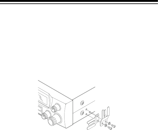
ATTACHING THE MICROPHONE
HOLDER
You can connect the microphone holder horizontally or vertically
to either side of the transceiver or to another location in your ve-
hicle.
Use the supplied screws and lock washers to secure the holder
to the side of the transceiver.
Or, follow these steps to attach the holder to another location in
the vehicle (such as the dashboard).
1. Using the holder as a template, mark the positions for the
mounting screw holes at the desired location.
2. At each marked position, drill a hole slightly smaller than the
supplied mounting screws.
Caution: Be careful not to drill into anything behind the
mounting surface.
3. Attach the holder at the mounting location using the sup-
plied machine screws and lock washers.
MOUNTING THE TRANSCEIVER
The most common mounting location for this transceiver is under
a vehicle's dashboard. If you use the HTX-10 as a base station,
however, you can place it on a desk, shelf, or table (see “Using
the Transceiver as a Base Station” on Page 14).
19-1110.fm Page 8 Friday, March 24, 2000 9:42 AM

9
If you are mounting the transceiver in a vehicle, choose a loca-
tion where:
• you can easily reach the transceiver.
• wires and cables are clear of the vehicle's pedals or other
moving parts.
• the transceiver is not directly in front of heating vents.
• all wires and cables can reach their connection points.
Warning: If you use the transceiver in a vehicle, mount it securely
to avoid damage to the transceiver or vehicle, and to avoid injury
to anyone in the vehicle during sudden starts or stops.
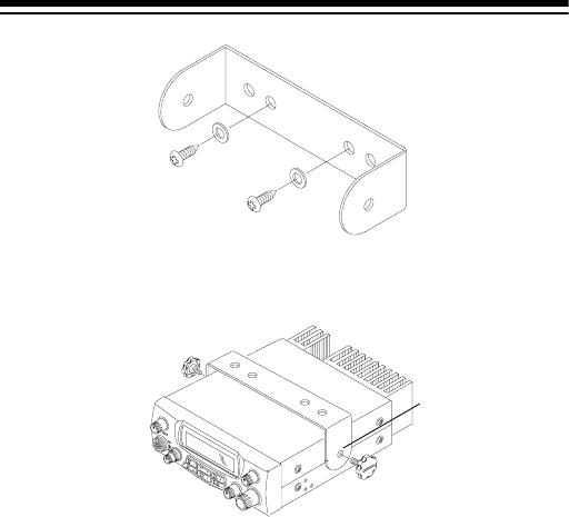
Follow these steps to mount the transceiver using the supplied
hardware.
1. Using the mounting bracket as a template, mark the posi-
tions for the screw holes on the mounting surface.
2. In each marked location, drill a hole slightly smaller than the
supplied mounting screws.
Caution: Be careful not to drill into objects behind the
mounting surface.
3. Using a Phillips screwdriver, attach the mounting bracket to
the mounting surface with the supplied mounting screws
and flat washers.
19-1110.fm Page 9 Friday, March 24, 2000 9:42 AM
10
4. Attach the transceiver to the mounting bracket using the
supplied rubber washers and mounting knobs.
CONNECTING AN ANTENNA
There are many different types of transceiver antennas for mobile
transceivers. Each antenna type has its own benefits, so choose
the one that best meets your needs. Your local RadioShack store
sells a wide variety of antennas.
Note: If you are using this transceiver as a base station, see “Us-
ing the Transceiver as a Base Station” on Page 14.
When you choose an antenna, keep in mind that for the best
performance you should mount the antenna:
• as high as possible on the vehicle
• as far as possible from sources of electrical noise
•vertically
(Rubber washer
s
not shown)
19-1110.fm Page 10 Friday, March 24, 2000 9:42 AM
11
Once you choose an antenna, follow
its mounting instructions. Then route
the cable to the transceiver and con-
nect the cable to the ANT jack on the
back of the transceiver.
Cautions:
• Avoid routing the cable next to
sharp edges or moving parts,
which might damage the cable.
• Do not run the cable next to
power cables or other radio
antenna cables.
• Do not run the cable through the engine compartment or
other areas that produce extreme heat.
To achieve your radio's maximum range, adjust the antenna's
Standing Wave Ratio (SWR). You can use an SWR meter (not
supplied) to adjust the SWR for your antenna.
Follow the instructions supplied with the SWR meter and antenna
to adjust your antenna's SWR to the lowest possible value. SWR
values of 2.0:1 are generally acceptable, with readings of 1.5:1 or
lower being more desirable.
Caution: You might damage your transceiver if you use it at a
high SWR value.
19-1110.fm Page 11 Friday, March 24, 2000 9:42 AM
12
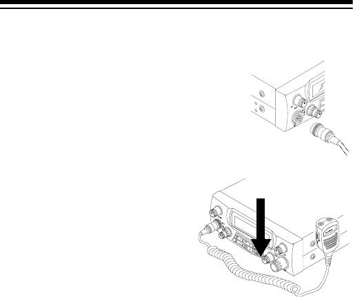
CONNECTING THE MICROPHONE
1. Align the slot on the bottom of the
microphone’s plug with the ridge
inside the MIC jack. Then fully insert
the plug into the jack.
2. Turn the plug’s locking nut clock-
wise to tighten it.
3. Slide the microphone onto
the microphone holder.
To disconnect the microphone,
unscrew the locking nut and
gently pull out the microphone
plug. Never pull on the micro-
phone cable to disconnect the
microphone.
CONNECTING AN OPTIONAL EXTERNAL
SPEAKER
You can connect an external speaker to the transceiver. The ex-
ternal speaker you use with the transceiver should have an im-
pedance of 8 ohms and be able to handle 3 to 10 watts of power.
The speaker’s cable must have a 1/8-inch (3.5–mm) plug. Both ac-
cessories are available at your local RadioShack store.
19-1110.fm Page 12 Friday, March 24, 2000 9:42 AM
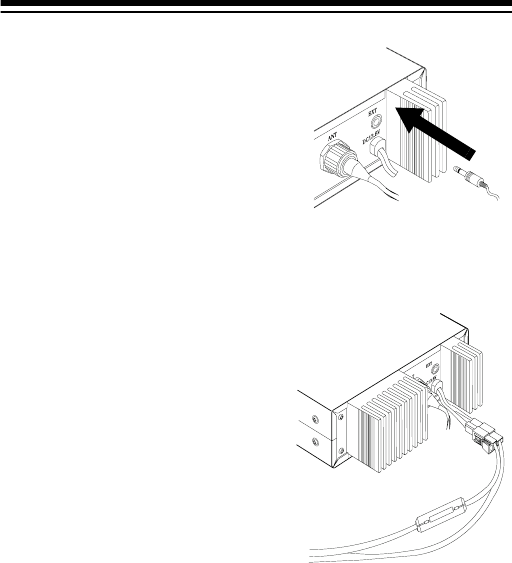
13
To connect the external speaker to
the transceiver, insert the speaker's
plug into the EXT jack on the back of
the transceiver
Note: Connecting an external
speaker disconnects the transceiv-
er's internal speaker.
USING VEHICLE BATTERY POWER
Follow these steps to connect the
transceiver to your vehicle’s bat-
tery power.
1. Connect the red wire (with in-
line fuse holder) from the
back of the transceiver to a
point in your vehicle's fuse
block that has power only
when the ignition is in the
ACC (accessory) or ON posi-
tion.
2. Connect the black wire to a
metal part of the vehicle's
frame (chassis ground).
Red wire to
positive (+) terminal
Black wire to
negative (-) terminal
19-1110.fm Page 13 Friday, March 24, 2000 9:42 AM

14
Caution: Do not connect the black wire to a non-metallic
(plastic) part, or to any part insulated from the vehicle's
chassis by a non-metallic part.
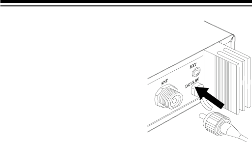
3. Connect the single connector end of the power cord to the
connector on the back of the transceiver.
USING THE TRANSCEIVER AS A BASE
STATION
Although this transceiver is designed mainly for mobile use, you
can also use it as a base station with an AC power source. For
base station installation, you need these items.
• a 12-volt DC power supply that can supply at least 7 amps
Caution: Most 12-volt DC power supplies plug into a stan-
dard AC outlet to produce DC power. Before connecting
your transceiver to a 12-volt DC power supply, read and fol-
low the instructions included with the power supply.
• base station antenna
• coaxial antenna cable and connectors
• external 8-ohm speaker
Note: Your local RadioShack store carries everything you
need to use the transceiver as a base station.
19-1110.fm Page 14 Friday, March 24, 2000 9:42 AM
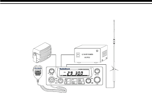
15
Follow these steps to install the transceiver as a base station.
1. Mount the base station antenna as described in its owner's
manual.
Warning: Use extreme caution when you install or remove
a base station antenna. If the antenna starts to fall, let it go!
It could contact overheard power lines. If the antenna
touches a power line, contact with the antenna, mast, cable,
or guy wires can cause electrocution and death. Call the
power company to remove the antenna. DO NOT attempt to
do so yourself.
2. Connect the antenna to the ANT jack on the back of the
transceiver.
3. Connect the transceiver's black power wire to the negative
(–) terminal on the DC power supply.
4. Connect the transceiver's red wire (with in-line fuse holders)
to the positive (+) terminal on the DC power supply.
5. Connect the single–connector end of the power cord to the
connector on the back of the transceiver.
6. Connect the DC power supply to a standard AC outlet.
19-1110.fm Page 15 Friday, March 24, 2000 9:42 AM
16
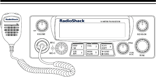
A QUICK LOOK AT THE CONTROLS
OFF/VOLUME — turns the radio on/off; adjusts the volume
RF-G/MIC-G — attenuates strong signals; reduces the micro-
phone’s gain and SSB transmitting power
STEP/NB/1 — selects the frequency tuning step; turns the noise
blanker on/off; selects memory Channel 1
CALL/2 — quickly recalls a frequency in memory Channel 2; se-
lects memory Channel 2
SCAN/SHIFT/3 — starts/stops scanning; selects the frequency
shift; selects memory Channel 3
LCR/4 — recalls the last tuned channel; selects memory Channel 4
MODE/T-LOW/5 — selects the operation band, AM/FM/USB/LSB;
turns hi-cut filter on/off; selects memory Channel 5
M-LOAD/M-SAVE — loads from/saves to a memory location
FINE/PUSH FUNC — adjusts fine tuning; activates second function
SQUELCH — sets the squelch level to block weak signals
TUNE — selects a frequency
19-1110.fm Page 16 Friday, March 24, 2000 9:42 AM
17
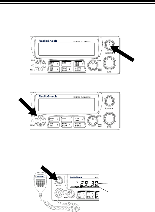
OPERATION
SETTING SQUELCH AND RECEIVING
1. Rotate SQUELCH fully counterclockwise.
2. Rotate RF-G fully clockwise.
3. To turn on the transceiver, rotate OFF/VOLUME clockwise
until it clicks. The display lights and the frequency appears.
A bar graph also appears which shows the received signal’s
strength.
4. Set OFF/VOLUME to a comfortable listening level.
5. Rotate SQUELCH clockwise until you hear a hissing sound.
Then slowly rotate SQUELCH counterclockwise just until the
noise stops.
Frequency
Bar Graph
19-1110.fm Page 17 Friday, March 24, 2000 9:42 AM
18
Note: If the transceiver picks up unwanted weak transmis-
sions, rotate RF-G slightly counterclockwise to decrease the
transceiver’s sensitivity to signals. The transceiver blocks
the weak transmissions.
6. Repeatedly press MODE to select the desired band (FM,
AM, USB (upper sideband), or LSB (lower sideband)).
7. Rotate TUNE or press UP or DN on the top of the micro-
phone to select a frequency.
8. To turn off the transceiver, rotate OFF/VOLUME counterclock-
wise until it clicks.
TRANSMITTING
Notes:
• Do not attempt to transmit unless you possess a valid ama-
teur radio license.
• We recommend you try receiving before you transmit.
1. Follow Steps 1–7 in “Setting Squelch and Receiving” on
Page 17.
2. Turn MIC-G fully clockwise.
19-1110.fm Page 18 Friday, March 24, 2000 9:42 AM
19
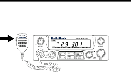
3. To transmit, hold down the push-to-talk button on the micro-
phone, hold the microphone 2–3 inches from your mouth,
and speak in a normal tone of voice. TX appears along with
a bar graph which shows the strength of your transmission.
4. When you finish transmitting, release the PTT button. TX
and the signal strength bars disappear.
5. To turn off the transceiver, rotate OFF/VOLUME counterclock-
wise until it clicks.
NOTES ON SSB RECEPTION
• If the voice sounds distorted, slowly rotate FINE to bring the
signal into its natural voice tonal range.
• An SSB signal produces a fluttering, unintelligible sound
when received in the AM mode. Set the mode switch to
either LSB or USB, and adjust FINE. If the voice is still not
intelligible, it might be an SSB signal operating on the other
sideband — try the other SSB mode.
19-1110.fm Page 19 Friday, March 24, 2000 9:42 AM

20
SPECIAL FEATURES
USING THE SPECIAL FEATURES
Your transceiver has several advanced features that give you ad-
ditional control and convenience while using it.
This list provides additional information about your transceiver’s
special features.
Feature See:
Step — let’s you change the incre-
ment you set to tune frequencies in
the 10-meter band.
Page 21
Call — recalls a specific frequency in
memory channel 2. Page 22
Scan — scans incoming signals. Page 22
Last Channel Recall — returns to the
last channel that was transmitted. Page 23
M-LOAD — recalls frequencies stored
in memory Channels 1–5. Page 23
NB (Noise Blanker) — reduces elec-
trical noise. Page 23
Shift — lets you set the frequency shift
direction and offset frequency. Page 24
T-LOW (Tone Low) — turns the high-
cut filter on or off. Page 24
M-SAVE (Memory Save) — saves up
to five frequencies into memory chan-
nels.
Page 25
FINE (Clarifier) — tunes in stations or
tunes out interference broadcast using
an SSB signal.
Page 25
19-1110.fm Page 20 Friday, March 24, 2000 9:42 AM
21
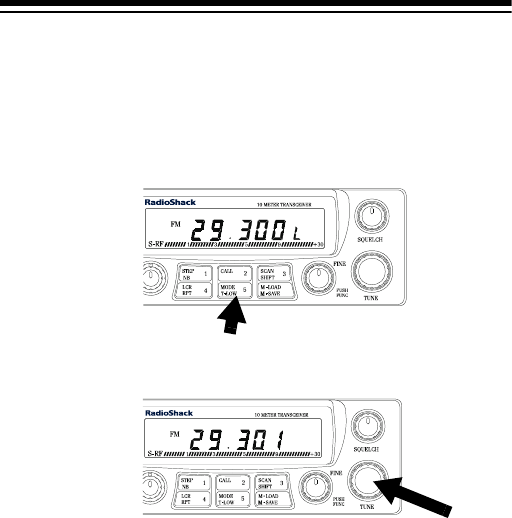
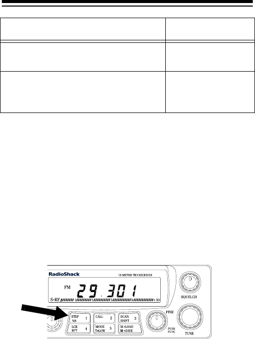
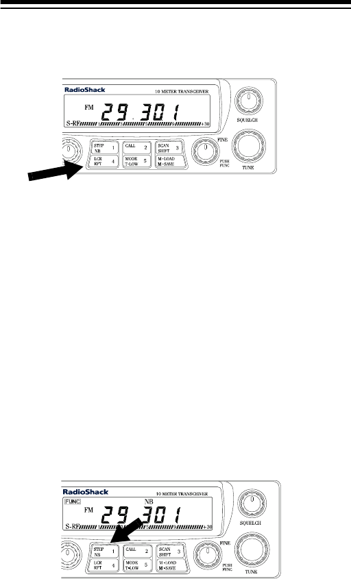
Using STEP
Repeatedly press STEP to select the frequency step your trans-
ceiver displays when it shows a frequency. As you press STEP,
one of the three frequency digits flashes for about 2 seconds to
show which digit is selected. The increment that the selected
digit displays is:
• the rightmost digit: 1 kHz
• the second digit from the right: 10 kHz
• the third digit from the right: 100 kHz
RF-G (RF Gain) — attenuates strong
signals. Page 26
MIC-G (Microphone Gain) —
reduces the microphone gain and
SSB transmitting power,
Page 26
Feature See:
19-1110.fm Page 21 Friday, March 24, 2000 9:42 AM
22
Using CALL
The transceiver’s call memory lets you quickly recall a specific
frequency in memory Channel 2.
Note: See “Using M-SAVE (Memory Save)” on Page 25 for more
information about storing a frequency in memory channel 2.
Press CALL to recall the stored frequency at any time. The fre-
quency flashes.
Press CALL again and the last selected frequency appears.
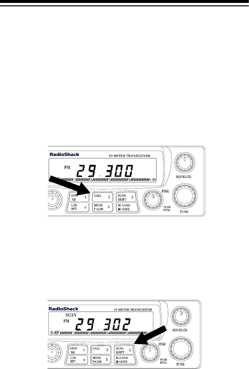
Using SCAN
Press SCAN to scan incoming signals. SCAN appears and the
transceiver stops for 5 seconds on each channel when it detects
a signal.
To stop scanning, press SCAN or the PTT button on the micro-
phone. SCAN disappears.
19-1110.fm Page 22 Friday, March 24, 2000 9:42 AM
23
Using LCR (Last Channel Recall)
Press LCR to return to the last channel you selected.
Using M-LOAD
You can recall frequencies stored in memory Channels 1–5.
Note: See “Using M-SAVE (Memory Save)” on Page 25 for more
information about storing frequencies in memory channels.
To recall a memory channel, press M-LOAD so L appears, then,
press the desired memory channel number.
Using NB (Noise Blanker)
If the transceiver’s reception is disturbed by interference from
electrical noise (such as ignition noise), you can reduce the noise
by using the transmitter’s noise blanker feature. To turn on or off
the noise blanker, press PUSH FUNC then NB. NB appears while
the noise blanker is on.
19-1110.fm Page 23 Friday, March 24, 2000 9:42 AM
24
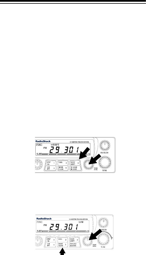
Using SHIFT
The transceiver’s shift function lets you set the transmit frequency
shift from the receive frequency in either direction within the
range of 0.0 Hz to 990 kHz.
Follow these steps to set the frequency shift direction and offset
frequency.
1. To set the frequency shift direction to +, press PUSH FUNC
then press SHIFT while FUNC appears. +SHIFT appears.
Press PUSH FUNC and SHIFT again while FUNC appears to
set the frequency shift direction to -. -SHIFT appears.
2. Press PUSH FUNC then SHIFT for about 3 seconds. 000
appears.
3. Rotate TUNE to set the offset frequency to any frequency
from 0 to 990 kHz.
4. To exit, hold down PUSH FUNC and SHIFT together for about
3 seconds.
Using T-LOW (Tone-Low)
Press PUSH FUNC then T-LOW to turn the high-cut filter on or off.
LOW appears when the high-cut filter is on.
19-1110.fm Page 24 Friday, March 24, 2000 9:42 AM

25
Using M-SAVE (Memory Save)
Follow these steps to save up to five frequencies into memory
channels.
1. Select the desired frequency.
2. Press PUSH FUNC then M-SAVE. S appears.
3. While S appears, press the desired memory channel num-
ber. The transceiver stores the frequency you selected into
the memory channel you selected.
4. To recall a frequency you stored, see “Using M-LOAD” on
Page 23.
Using FINE (Clarifier)
When you listen to an SSB signal, rotate FINE to tune in slightly
off-frequency stations or to tune out interference from adjacent
channels.
19-1110.fm Page 25 Friday, March 24, 2000 9:42 AM
26
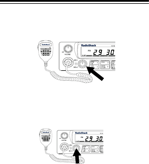
Using RF-G (RF Gain)
When you receive an extremely strong signal, rotate RF-G coun-
terclockwise to attenuate the signal.
Using MIC-G (Microphone Gain)
Rotate MIC-G to adjust the transmitter’s microphone gain and
SSB transmitting power for the best audio quality.
TURNING THE KEY TONE ON AND OFF
The transceiver is preset to sound a tone each time you press a
key. To turn the transceiver’s key tone on or off, turn on the trans-
ceiver while holding down the push-to-talk button on the micro-
phone.
19-1110.fm Page 26 Friday, March 24, 2000 9:42 AM
27
CARE AND MAINTENANCE
Your HTX-10 10-Meter Transceiver is an example of superior
design and craftsmanship. The following suggestions will help
you care for your transceiver so you can enjoy it for years.
Keep the transceiver dry. If it gets wet, wipe it dry
immediately. Liquids might contain minerals that
can corrode the electronic circuits.
Use and store the transceiver only in normal tem-
perature environments. Temperature extremes
can shorten the life of electronic devices and dis-
tort or melt plastic parts.
Keep the transceiver away from dust and dirt,
which can cause premature wear of parts.
Handle the transceiver gently and carefully.
Dropping it can damage circuit boards and cases
and can cause the transceiver to work improper-
ly.
Wipe the transceiver with a damp cloth occasion-
ally to keep it looking new. Do not use harsh
chemicals, cleaning solvents, or strong deter-
gents to clean the transceiver.
Modifying or tampering with the transceiver’s internal compo-
nents can cause a malfunction and might invalidate its warran-
ty and void your FCC authorization to operate it. If your
transceiver is not performing as it should, take it to your local
RadioShack store for assistance.
19-1110.fm Page 27 Friday, March 24, 2000 9:42 AM

28
TROUBLESHOOTING
If your transceiver is not working as it should, these suggestions
might help you eliminate the problem. If the transceiver still does
not operate properly, take it to your local RadioShack store for as-
sistance.
Problem Possible Causes Remedies
Trouble with
reception.
The squelch might
need to be adjusted. Adjust the
squelch.
The transmitter
might not be set to
an operating fre-
quency.
Tune the trans-
ceiver to an oper-
ating frequency.
The microphone
might not be con-
nected.
Make sure the
microphone is
connected.
The antenna might
not be connected. Make sure the
antenna is con-
nected.
The receive mode
might not be properly
set.
Set the receive
mode to FM, AM,
LSB, or USB.
Trouble with
transmission.
The antenna might
not be connected. Make sure the
antenna is con-
nected.
The microphone
might not be con-
nected.
Make sure the
microphone is
connected.
The microphone’s
push–to–talk button
might not be fully
pressed in.
Press the micro-
phone’s button in
fully.
19-1110.fm Page 28 Friday, March 24, 2000 9:42 AM

29
The transceiver should be serviced only by a qualified radio
technician. If you still have problems, take your transceiver to a
local RadioShack store for assistance.
NOISE REDUCTION
Because your transceiver is exceptionally quiet, any noise you
hear is probably from an external source in your vehicle such as
your vehicle’s alternator, radio, or spark plugs.
To solve the problem, you must go to the noise's source. You
can determine the noise's source by turning off the engine and
operating the transceiver with your vehicle's ignition set to ACC.
If the noise decreases, the problem is in your vehicle’s ignition
or electrical system.
Here are a few hints to help you reduce or eliminate such
noise:
• Make all transceiver power and antenna wires as short as
possible.
• Route the power wires away from the antenna wires.
Trouble with
transmission
(continued)
The microphone’s
gain might not be
properly set.
Adjust MIC-G.
Transceiver
does not work
at all.
The power cord
might not be con-
nected.
Make sure the
power cord is con-
nected.
The power cord’s
fuse might be blown. Replace the fuse
(see “Replacing
the Fuse” on Page
30).
Problem Possible Causes Remedies
19-1110.fm Page 29 Friday, March 24, 2000 9:42 AM

30
• Be sure that the chassis ground connection is secure.
• Replace old ignition wires with new, high-voltage, noise sup-
pression wires.
• Install noise suppressors on your spark plugs, or install new
spark plugs that have built in noise suppressors.
• If problems persist, check your alternator/generator and reg-
ulator gauges. You can reduce the noise from these sources
by using bypass capacitors at the various output voltage
points.
Your local RadioShack store has a wide selection of noise sup-
pression accessories.
REPLACING THE FUSE
If the HTX-10 stops operating, you might need to replace the red
power wire’s fuse with the supplied spare fuse.
Caution: Do not use a fuse with ratings other than those speci-
fied here. Doing so might damage your transceiver.
Follow these steps to replace your transceiver’s fuse.
1. Make sure the power source and transceiver are both off.
2. Pull the latches apart on the fuse holder until it opens.
3. If the fuse is blown, replace it. Use only a standard 11/4 × 1/4
inch fast-acting fuse with the proper rating. The fuse must
be 10 amps.
19-1110.fm Page 30 Friday, March 24, 2000 9:42 AM

31
Caution: The supplied fuse has the proper ratings. Make
sure you replace a fuse only with another fuse of the same
rating.
4. Reassemble the fuse holder by squeezing it together until it
snaps shut.
19-1110.fm Page 31 Friday, March 24, 2000 9:42 AM

32
SPECIFICATIONS
GENERAL
Frequency Range ........................... 28.000 MHz to 29.699 MHz
Tuning Step ......................... 1 kHz/10 kHz/100 kHz (selectable)
Frequency Generation ........................... Digital PLL Synthesizer
Antenna Connector ............................ 50 ohm coaxial connector
Microphone ........................................... Electret condenser type
Operating Temperature ................... –4° to 122°F (–10° to 55°C)
Power Source ............. 12–16V DC, negative or positive ground
Speaker ................................................................ 8 ohm, 2 watt
Impedance ...................................................................... 50 ohm
Dimensions (HWD) ........................... 61/16 × 23/64 × 941/64 inches
(154 × 52 × 248 mm)
Weight (without batteries)................................................. 2.65 lb
(1.2 kg)
Accessories ............................ Microphone, Microphone Holder,
Mounting Hardware, Mounting Bracket,
DC Power Cord, Spare Fuse
RECEIVER
Sensitivity .................................................. 0.5
µV for 10 dB S/N
Audio Output @ 10% THD (External) ................ 2.5 W at 8 ohm
Selectivity ................................................................... 50 dB min
Intermodulation ........................................................... 60 dB min
Distortion ..................................................................... 10% max
S/N Ratio .................................................................... 40 dB min
IF Rejection ........................................................ 70 dB or better
19-1110.fm Page 32 Friday, March 24, 2000 9:42 AM

33
TRANSMITTER
Power Output ....................................... 7w (AM), 25w (FM/SSB)
Distortion ............................................................................... 5%
Deviation ......................................................................... ±2 kHz
S/N Ratio............................................................................ 40 dB
Spurious Emission ............................................ –65 dB or better
Battery Drain:
At max output power ........................... AM Less than 3.0 A,
FM Less than 5.0 A, SSB 5.0 A
At no modulation ................................. AM Less than 3.0 A,
FM Less than 5.0 A, SSB 1.0 A
Specifications are typical; individual units might vary. Specifica-
tions are subject to change and improvement without notice.
19-1110.fm Page 33 Friday, March 24, 2000 9:42 AM

34
NOTES
19-1110.fm Page 34 Friday, March 24, 2000 9:42 AM

35
19-1110.fm Page 35 Friday, March 24, 2000 9:42 AM

RadioShack
A Division of Tandy Corporation
Fort Worth, Texas 76102
03A00 Printed in Korea
Limited Ninety-Day Warranty
This product is warranted by RadioShack against manufacturing defects in material
and workmanship under normal use for ninety (90) days from the date of purchase
from RadioShack company-owned stores and authorized RadioShack franchisees
and dealers. EXCEPT AS PROVIDED HEREIN, RadioShack MAKES NO EX-
PRESS WARRANTIES AND ANY IMPLIED WARRANTIES, INCLUDING THOSE
OF MERCHANTABILITY AND FITNESS FOR A PARTICULAR PURPOSE, ARE
LIMITED IN DURATION TO THE DURATION OF THE WRITTEN LIMITED WAR-
RANTIES CONTAINED HEREIN. EXCEPT AS PROVIDED HEREIN, RadioShack
SHALL HAVE NO LIABILITY OR RESPONSIBILITY TO CUSTOMER OR ANY
OTHER PERSON OR ENTITY WITH RESPECT TO ANY LIABILITY, LOSS OR
DAMAGE CAUSED DIRECTLY OR INDIRECTLY BY USE OR PERFORMANCE
OF THE PRODUCT OR ARISING OUT OF ANY BREACH OF THIS WARRANTY,
INCLUDING, BUT NOT LIMITED TO, ANY DAMAGES RESULTING FROM INCON-
VENIENCE, LOSS OF TIME, DATA, PROPERTY, REVENUE, OR PROFIT OR ANY
INDIRECT, SPECIAL, INCIDENTAL, OR CONSEQUENTIAL DAMAGES, EVEN IF
RadioShack HAS BEEN ADVISED OF THE POSSIBILITY OF SUCH DAMAGES.
Some states do not allow limitations on how long an implied warranty lasts or the ex-
clusion or limitation of incidental or consequential damages, so the above limitations
or exclusions may not apply to you.
In the event of a product defect during the warranty period, take the product and the
RadioShack sales receipt as proof of purchase date to any RadioShack store. Ra-
dioShack will, at its option, unless otherwise provided by law: (a) correct the defect
by product repair without charge for parts and labor; (b) replace the product with one
of the same or similar design; or (c) refund the purchase price. All replaced parts
and products, and products on which a refund is made, become the property of Ra-
dioShack. New or reconditioned parts and products may be used in the performance
of warranty service. Repaired or replaced parts and products are warranted for the
remainder of the original warranty period. You will be charged for repair or replace-
ment of the product made after the expiration of the warranty period.
This warranty does not cover: (a) damage or failure caused by or attributable to acts
of God, abuse, accident, misuse, improper or abnormal usage, failure to follow in-
structions, improper installation or maintenance, alteration, lightning or other inci-
dence of excess voltage or current; (b) any repairs other than those provided by a
RadioShack Authorized Service Facility; (c) consumables such as fuses or batter-
ies; (d) cosmetic damage; (e) transportation, shipping or insurance costs; or (f) costs
of product removal, installation, set-up service adjustment or reinstallation.
This warranty gives you specific legal rights, and you may also have other rights
which vary from state to state.
RadioShack Customer Relations, 200 Taylor Street, 6th Floor, Fort Worth, TX 76102
We Service What We Sell
12/99
19-1110.fm Page 36 Friday, March 24, 2000 9:42 AM
