Radio Shack Scanner Pro 2052 Users Manual 432_1
PRO-2052 to the manual ae38d80e-d020-4996-aad1-d60f957a7534
2015-01-21
: Radio-Shack Radio-Shack-Scanner-Pro-2052-Users-Manual-352542 radio-shack-scanner-pro-2052-users-manual-352542 radio-shack pdf
Open the PDF directly: View PDF ![]() .
.
Page Count: 72
Owner’s Manual Cat. No. 20-432
PRO-2052
1000-Channel Dual Trunking
TrunkTracker Home Scanner
Please read before using this equipment.
20-432.fm Page 1 Friday, July 14, 2000 11:30 AM

2
INTRODUCTION
Your new RadioShack PRO-2052
1000-Channel Dual Trunking Trunk-
Tracker Home Scanner is one of a
new generation of scanners designed
to track Motorola Type I, Type II
(such as Smartnet and Privacy
Plus), GE/Ericsson EDACS, and hy-
brid analog trunking systems, which
are extensively used in many 800
MHz, 900 MHz and UHF communica-
tion systems.
Trunking communications systems let
a large group of 2-way radio users (or
even different groups of 2-way radio
users) efficiently use a group of fre-
quencies. Instead of selecting a spe-
cific frequency for a transmission, the
2-way radio user simply selects a talk
group. The trunking system automati-
cally transmits the call on the first
available frequency, and also sends a
code that uniquely identifies that 2-
way radio user’s transmission on a dif-
ferent frequency called a data chan-
nel.
Since the trunking system might send
individual 2-way radio user’s calls and
response transmissions on different
frequencies, it is difficult to listen to
trunked communications using a regu-
lar scanner. The PRO-2052 monitors
the data channel frequency sent with
a 2-way radio user’s transmission and
instantly switches to an active fre-
quency, so you can hear the call and
response for that 2-way radio user
and easily “follow” the conversation.
The scanner also lets you scan con-
ventional transmissions, and is pre-
programmed with service-search
banks for convenience. By pressing a
single button, you can quickly search
those frequencies most commonly
used by public service and other
agencies without tedious and compli-
cated programming.
This scanner gives you direct access
to over 51,000 exciting frequencies,
including those used by police and fire
departments, ambulance services,
and amateur radio services, and you
can change your selection at any time.
FEATURES
Your scanner also has these special
features:
Flexible Operation — you can track
both Motorola and GE/Ericsson trunk-
ing systems (used by most trunking
communications systems today), let-
ting you hear more calls than many
standard trunking scanners.
Frequency Coverage to 1.3 GHz —
provides a wide range of frequencies
you can listen to.
Twenty Channel-Storage Banks —
let you store 50 channels in each bank
(1000 total channels), letting you
group channels so you can more easi-
ly identify calls.
© 1999 Tandy Corporation.
All Rights Reserved.
RadioShack is a registered trademark used by Tandy Corporation.
HyperSearch and HyperScan are trademarks used by Tandy Corporation.
20-432.fm Page 2 Friday, July 14, 2000 11:30 AM

3
NWR-SAME/Weather Alert — you
can set the scanner to sound an alert
when it receives NOAA’s Specific
Area Message Encoding (SAME) cod-
ed weather emergency signal, provid-
ing more complete information about
weather conditions in your immediate
area and letting you avoid hearing
alerts for geographical areas that do
not interest you.
Remote PC Function — lets you con-
trol the PRO-2052 from your personal
computer.
Five Scan Lists — let you store up to
50 IDs in each tracking bank (up to a
total of 1000).
Triple-Conversion Circuitry — virtu-
ally eliminates any interference from
IF (intermediate frequency) images,
so you hear only the selected frequen-
cy.
Scan Delay — delays scanning for
about 2 seconds before moving to an-
other channel in conventional mode,
so you can hear more replies that are
made on the same channel. In trunk
scanning mode, it delays for about 5
seconds before moving to another ID.
Lock-Out Function — lets you set
your scanner to skip over specified
channels or frequencies when scan-
ning or searching, and skip over IDs
when tracking trunked systems.
Priority Channels — lets you pro-
gram one channel in each bank (10 in
all). As the scanner scans a bank, it
checks the bank’s priority channel ev-
ery 2 seconds so you don't miss trans-
missions on that channel.
Five Service-Search Banks — let
you search preset frequencies in sep-
arate public service, police, fire/emer-
gency, aircraft, and weather banks, to
make it easy to locate specific types of
calls.
HyperSearch and HyperScan —
let you set the scanner to search at up
to 300 steps per second (in frequency
bands with 5 kHz steps) and scan at
up to 50 channels per second, to help
you quickly find interesting broad-
casts. (The normal search speed is
100 steps per second).
Data Signal Skip — lets you set the
scanner to skip non-modulated or data
signals during scanning and searches.
This lets the scanner avoid non-voice
signals, making a scan or search fast-
er.
Manual Access — you can directly
access any stored channel by entering
that channel’s number.
Liquid-Crystal Display — makes it
easy to view and change program-
ming information.
Display Backlight — makes the
scanner easy to read in low-light situa-
tions.
20-432.fm Page 3 Friday, July 14, 2000 11:30 AM

4
Supplied Telescoping Antenna —
provides good reception of strong lo-
cal signals.
External Antenna Terminal — lets
you connect an external antenna with
a BNC connector to the scanner for
improved reception of distant/weaker
signals.
Memory Backup — keeps the chan-
nel frequencies stored in memory in
the event AC power goes out.
Key Confirmation Tones — the
scanner sounds a tone when you per-
form an operation correctly, and an er-
ror tone if you make an error.
Duplicate Channel Alert — warns
you when the frequency you are stor-
ing already exists in memory.
Disconnect Tone Detect — the scan-
ner automatically tunes to the trunking
data channel when it receives a dis-
connect transmission. You can turn
this feature off to continuously monitor
a channel with a weak transmission
during disconnected conversations.
Your PRO-2052 scanner can receive
these bands:
Note: See “Specifications” on Page 68
for more information about the scan-
ner’s frequency steps.
Frequency
Range (MHz) Types of
Transmissions
29–29.7 10-Meter Ham Band
29.7–50 VHF Lo
50–54 6-Meter Ham Band
108–136.975 Aircraft
137–144 Military Land Mobile
144–148 2-Meter Ham Band
148–174 VHF Hi
179.75–215.75 VHF TV
216–225 1-Meter Ham Band
225–400 UHF Aircraft
400–420 Federal
Government
420–450 70-cm Ham Band
450–470 UHF Standard Band
470–512 UHF “T” Band
806–824
851–869
896–956
Public Service “800”
except
Cellular Band
1240–1300 25-cm Ham Band
20-432.fm Page 4 Friday, July 14, 2000 11:30 AM

5
FCC NOTICE
Your scanner might cause radio or TV
interference even when it is operating
properly. To determine whether your
scanner is causing the interference,
turn off your scanner. If the interfer-
ence goes away, your scanner is
causing it. Try the following methods
to eliminate the interference:
• Move your scanner away from the
receiver.
• Connect your scanner to an outlet
that is on a different electrical cir-
cuit from the receiver.
• Contact your local RadioShack
store for help.
Note: Mobile use of this scanner is
unlawful or requires a permit in some
areas. Check the laws in your area.
SCANNING LEGALLY
Your scanner covers frequencies
used by many different groups includ-
ing police and fire departments, ambu-
lance services, government agencies,
private companies, amateur radio ser-
vices, military operations, pager ser-
vices, and wireline (telephone and
telegraph) service providers. It is legal
to listen to almost every transmission
your scanner can receive. However,
there are some transmissions you
should never intentionally listen to.
These include:
• telephone conversations (cellular,
cordless, or other private means
of telephone signal transmission)
• pager transmissions
• any scrambled or encrypted trans-
missions
According to the Electronic Communi-
cations Privacy Act (ECPA), you are
subject to fines and possible imprison-
ment for intentionally listening to, us-
ing, or divulging the contents of such a
transmission unless you have the con-
sent of a party to the communication
(unless such activity is otherwise ille-
gal).
This scanner is designed to prevent
reception of illegal transmissions, in
compliance with the law which re-
quires that scanners be manufactured
in such a way as to not be easily mod-
ifiable to pick up those transmissions.
Do not open your scanner's case to
make any modifications that could al-
low it to pick up transmissions that it is
not legal to listen to. Doing so could
subject you to legal penalties.
We encourage responsible, legal
scanner use.
20-432.fm Page 5 Friday, July 14, 2000 11:30 AM

6
CONTENTS
Preparation ........................................................................................................... 8
Connecting an Antenna ................................................................................... 8
Connecting Power ........................................................................................... 9
Connecting an Extension Speaker ................................................................ 10
Connecting an Earphone/Headphones ......................................................... 11
Understanding Your Scanner ............................................................................ 12
A Look at the Front Panel .............................................................................. 12
A Look at the Display ..................................................................................... 14
Understanding Banks .................................................................................... 17
Understanding Trunking ................................................................................. 17
Operation ............................................................................................................ 18
Turning On the Scanner and Setting Squelch ............................................... 18
Storing Known Frequencies into Channels .................................................... 18
Searching Service Banks .............................................................................. 19
Limit Search ................................................................................................... 20
Scanning the Stored Channels ...................................................................... 21
Manually Selecting a Channel ....................................................................... 21
Deleting a Frequency from a Channel ........................................................... 21
Priority ........................................................................................................... 21
Special Features ................................................................................................ 23
Delay ............................................................................................................. 23
Turning Channel-Storage Banks On and Off ................................................. 23
Locking Out Channels and Frequencies ........................................................ 23
Turning the Key Tone On and Off ................................................................... 24
Changing Search Speeds .............................................................................. 25
Skipping Data Signals ................................................................................... 25
Using NWR-SAME and Weather Alert .......................................................... 25
Testing Weather Alert Reception ................................................................... 28
Trunk Scanning .................................................................................................. 30
Types of Trunking Systems ............................................................................ 30
Setting the Scanner to the Trunk Scanning Mode ......................................... 31
Setting Squelch for the Trunk Scanning Mode ............................................... 31
Programming Trunked Frequencies ............................................................... 32
Scanning a Trunked Bank .............................................................................. 33
Monitoring IDs ............................................................................................... 37
Channel Activity Indicators ............................................................................ 37
Scan Lists ...................................................................................................... 37
Scanning the Scan Lists ................................................................................ 39
Scanning Type I and Hybrid Trunked Systems .............................................. 40
20-432.fm Page 6 Friday, July 14, 2000 11:30 AM

7
PC Remote Function ......................................................................................... 46
Connecting the Scanner to a Computer ........................................................ 46
Setting the Remote Communication Format ................................................. 46
Turning the Remote Function On and Off ..................................................... 47
PC to Scanner Commands ........................................................................... 47
PC to Scanner Functions List ....................................................................... 48
Scanner to PC Responses ............................................................................ 52
Scanner Mode Codes ................................................................................... 53
A General Guide to Scanning ........................................................................... 55
Guide to Frequencies .................................................................................... 55
Guide to the Action Bands ............................................................................ 56
Band Allocation ............................................................................................. 57
Frequency Conversion .................................................................................. 63
Troubleshooting ................................................................................................. 64
Resetting the Scanner .................................................................................. 66
Care and Maintenance ...................................................................................... 67
Specifications .................................................................................................... 68
20-432.fm Page 7 Friday, July 14, 2000 11:30 AM
8
PREPARATION
This scanner is designed primarily for
use in the home as a base station.
You can place it on a desk, shelf, or
table.
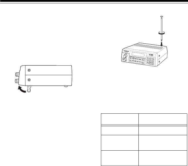
Your scanner’s front feet fold up or
down. Adjust them to give you the
best view of the display.
Your scanner’s display is protected
during shipment by a piece of film.
Peel off this film before you use the
scanner.
CONNECTING AN
ANTENNA
Connecting the Supplied
Antenna
You must install an antenna before
you can operate the scanner.
The supplied telescoping antenna
helps your scanner receive strong lo-
cal signals. To install the antenna,
thread it clockwise into the hole on the
scanner’s top.
The scanner’s sensitivity depends on
the antenna’s length and various envi-
ronmental conditions. For the best re-
ception of the transmissions you want
to hear, adjust the antenna’s length.
Connecting an Outdoor
Antenna
Instead of the supplied antenna, you
can connect an outdoor base-station
or mobile antenna (not supplied) to
your scanner using a BNC connector.
Your local RadioShack store sells a
variety of antennas. Choose the one
that best meets your needs.
When deciding on a mobile or base-
station antenna and its location, con-
sider these points:
Frequency Antenna Length
29–54 MHz Extend fully
108–400 MHz Collapse one
segment
406–1300 MHz Collapse both
segments
20-432.fm Page 8 Friday, July 14, 2000 11:30 AM

9
• The antenna should be as high as
possible on the vehicle or build-
ing.
• The antenna and its cable should
be as far as possible from sources
of electrical noise (appliances,
other radios, etc.).
• The antenna should be vertical for
the best performance.
To connect an optional base-station or
mobile antenna, first remove the sup-
plied antenna from the scanner. Al-
ways use 50-ohm coaxial cable, such
as RG-58 or RG-8, to connect the
base-station or mobile antenna. For
lengths over 50 feet, use RG-8 low-
loss dielectric coaxial cable. If the an-
tenna cable’s connector does not fit in
the ANT. jack, you might also need a
Motorola-to-BNC antenna plug adapt-
er, such as RadioShack Cat. No. 278-
117. Your local RadioShack store car-
ries a wide variety of coaxial antenna
cable and connectors.
Once you choose an antenna, follow
the mounting instructions supplied
with the antenna. Then route the an-
tenna’s cable to the scanner and con-
nect the cable to the ANT. jack on the
back of the scanner.
Cautions:
• Do not run the cable over sharp
edges or moving parts that might
damage it.
• Do not run the cable next to power
cables or other antenna cables.
Warning: Use extreme caution
when you install or remove an out-
door antenna. If the antenna starts to
fall, let it go! It could contact over-
head power lines. If the antenna
touches a power line, contact with
the antenna, mast, cable, or guy
wires can cause electrocution and
death. Call the power company to re-
move the antenna. DO NOT attempt
to do so yourself.
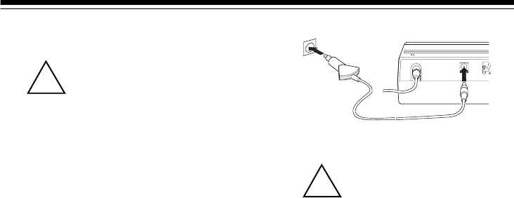
CONNECTING POWER
Using AC Power
The scanner’s supplied AC adapter
lets you power the scanner from a
standard AC outlet. To connect power
to the scanner, insert the AC adapter’s
barrel plug into the DC 12V jack on the
back of the scanner, then plug the AC
adapter into a standard AC outlet.
ANT
20-432.fm Page 9 Friday, July 14, 2000 11:30 AM
10
Cautions:
You must use a Class 2
power source that sup-
plies 12V DC and deliv-
ers at least 500 mA. Its center tip
must be set to positive and its
plug must fit the scanner's DC 12V
jack. The supplied adapter meets
these specifications. Using an
adapter that does not meet these
specifications could damage the
scanner or the adapter.
• Always connect the AC adapter to
the scanner before you connect it
to AC power. When you finish, dis-
connect the adapter from AC
power before you disconnect it
from the scanner.
Warning: Do not use the AC adapt-
er’s polarized plug with an extension
cord receptacle unless the blades can
be fully inserted to prevent blade ex-
posure.
Using Your Vehicle’s Battery
Power
If your AC power fails (during an
emergency, for example), you can
power your scanner from your vehi-
cle’s cigarette lighter socket with an
optional DC cigarette lighter power ca-
ble, (not supplied).
To connect an optional DC cigarette
lighter power cable, insert its barrel
plug into the DC 12V jack on the back
of the scanner, then plug the power
cable into your vehicle’s cigarette
lighter socket.
Cautions:
You must use a power
source that supplies 12V
DC and delivers at least
500 mA. Its center tip must be set
to positive and its plug must fit the
scanner's DC 12V jack. The sup-
plied adapter meets these specifi-
cations. Using an adapter that
does not meet these specifica-
tions could damage the scanner
or the adapter.
• Always connect the adapter to the
scanner before you connect it to
the power source. When you fin-
ish, disconnect the DC adapter
from the power source before you
disconnect it from the scanner.
Note: If you use a cigarette lighter
power cable and your vehicle’s engine
is running, you might hear electrical
noise from the engine while scanning.
This is normal.
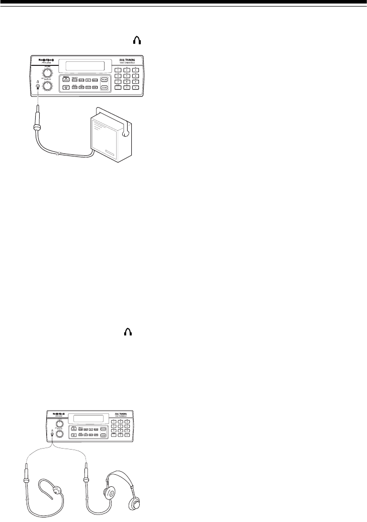
CONNECTING AN
EXTENSION SPEAKER
In a noisy area, an amplified extension
speaker (available at your local Ra-
dioShack store) positioned in the right
place, might provide more comfortable
listening.
!
D C 12V
ANT
!
20-432.fm Page 10 Friday, July 14, 2000 11:30 AM
11
Plug the speaker cable’s 1/8-inch (3.5-
mm) plug into your scanner’s jack.
Note: Connecting an external speaker
disconnects the scanner’s internal
speaker.
CONNECTING AN
EARPHONE/
HEADPHONES
For private listening, you can connect
an earphone or headphones with a 1/8-
inch (3.5-mm) plug to the jack on
the front of the scanner. (Your local
RadioShack store carries a wide se-
lection of earphones and head-
phones). This automatically dis-
connects the internal speaker.
Listening Safely
To protect your hearing, follow these
guidelines when you use an earphone
or headphones.
• Do not listen at extremely high
volume levels. Extended high-
volume listening can lead to per-
manent hearing loss.
•Set
VOLUME to the lowest setting
before you begin listening. After
you begin listening, adjust VOL-
UME to a comfortable level.
• Once you set VOLUME, do not
increase it. Over time, your ears
adapt to the volume level, so a
volume level that does not cause
discomfort might still damage your
hearing.
20-432.fm Page 11 Friday, July 14, 2000 11:30 AM
12
UNDERSTANDING YOUR SCANNER
Once you understand a few simple terms we use in this manual and familiarize
yourself with your scanner’s features, you can put the scanner to work for you. You
simply determine the type of communications you want to receive, then set the
scanner to scan them.
A frequency is the tuning location of a station (expressed in kHz or MHz). To find
active frequencies, you can use the search function.
You can also search the service-search banks, which are preset groups of fre-
quencies categorized by type of service.
When you find a frequency, you can store it into a programmable memory location
called a channel, which is grouped with your other channels in a channel-storage
bank. You can then scan the channel-storage banks to see if there is activity on
the frequencies stored there. Each time the scanner finds an active frequency, it
stays on that channel until the transmission ends.
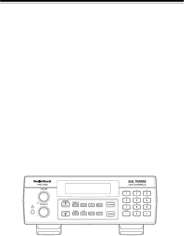
A LOOK AT THE FRONT PANEL
Your scanner’s keys might seem confusing at first, but this information should help
you understand each key’s function.
Note: Some of the scanner’s keys perform more than one function and are marked
with more than one label. The steps in this Owner’s Manual show only the label on
the key appropriate to the action being performed.
VOLUME Turns the scanner on or off and adjusts the volume.
SQUELCH Adjusts the scanner’s squelch.
20-432.fm Page 12 Friday, July 14, 2000 11:30 AM

13
SCAN In conventional scanning, scans through stored chan-
nels; in trunking mode, scans through the scan lists
and turns on/off the S-bit feature.
MANUAL Stops scanning and lets you directly enter a channel
number or frequency.
TRUNK Selects trunk scanning or conventional mode.
SVC (service) Selects a service bank; turns on/off the disconnect
tone detect feature.
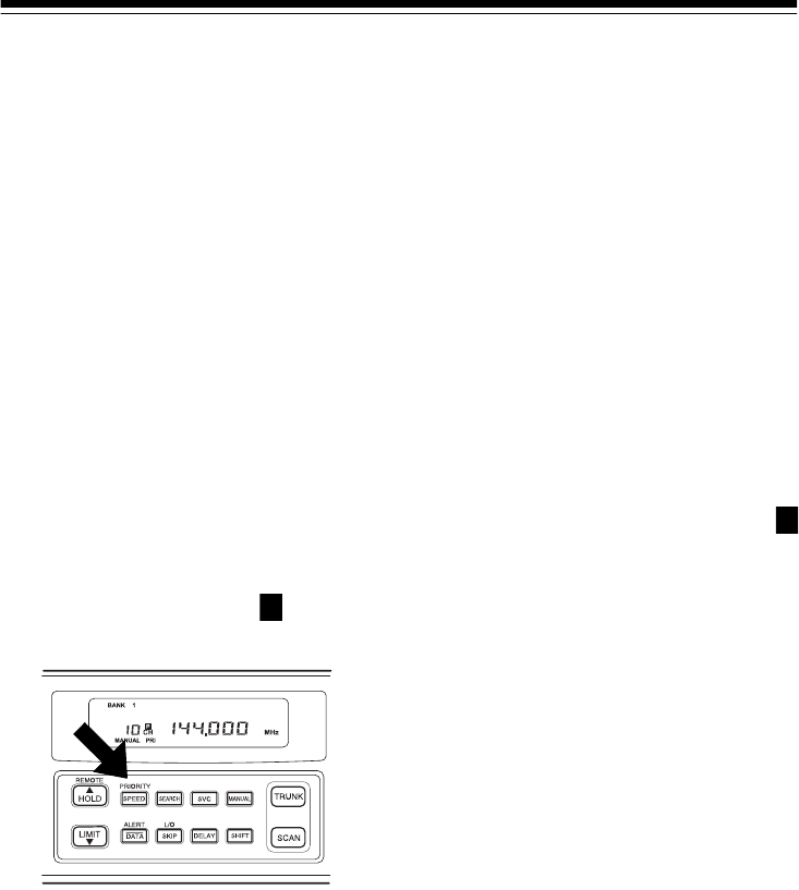
PRIORITY/SPEED Sets and turns on and off the priority feature; turns the
HyperSearch mode on and off; in Trunking mode, pro-
grams the priority ID.
Number Keys Each key has single-digit (0 to 9) and double-digit (11
to 20) labels. Use single digits to enter a channel, fre-
quency, ID number, or bank numbers 1 to 10. Use
double-digits to enter bank numbers 11 to 20.
CLEAR/•Clears an entry; enters a decimal point; in trunk scan-
ning mode, sets the range between fleet and sub-fleet
for Motorola Type 1 IDs and sets the range between
agency and fleet for Ericsson EDACS IDs.
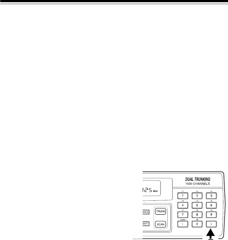
E (enter) Enters frequencies into channels; enters IDs into scan
lists.
LIMIT/▼Sets the frequency range; sets the search direction
and holds a frequency search.
DELAY Programs a 2-second delay for the selected channel,
a limit search, or each service scan. Also programs a
5-second delay in trunk scanning mode.
SEARCH Searches a specified frequency range to find frequen-
cies; searches for active IDs in the trunk scanning
mode.
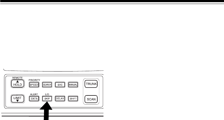
L/O/SKIP
(lock out/skip) Lets you lock out selected channels or frequencies;
lets you lock out a selected ID in the trunk scanning
mode.
20-432.fm Page 13 Friday, July 14, 2000 11:30 AM
14
REMOTE/HOLD/▲Turns the remote function on or off; holds on the cur-
rent ID in trunk scanning mode; sets the search direc-
tion and holds the frequency search.
DATA/ALERT Turns the data signal skip feature and the SAME alert
features on or off, or checks the current trunking bank
in trunk scanning mode.
SHIFT Press with number keys to select banks 11 through
20.
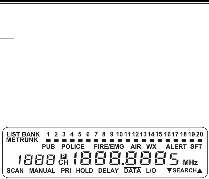
A LOOK AT THE DISPLAY
The display has indicators that show the scanner’s current operating status. This
quick look at the display will help you understand how your scanner operates.
LIST Appears with a number (1–5) to indicate the list num-
ber.
BANK Appears with numbers (1–20) to indicate the scan
bank.
PUB Indicates (along with the activity indicator) that the
scanner is searching the public safety service bank.
POLICE Indicates (along with the activity indicator) that the
scanner is searching the police service bank.
FIRE/EMG Indicates (along with the activity indicator) that the
scanner is searching the fire/emergency service bank.
AIR Indicates (along with the activity indicator) that the
scanner is searching the air service bank.
20-432.fm Page 14 Friday, July 14, 2000 11:30 AM

15
WX Indicates (along with the activity indicator) that the
scanner is searching the weather service bank.
TRUNK Appears when the scanner is in trunk scanning
mode. 1–20 appears as the bank number or list
number.
Shows which service bank is currently active. Shows
(activity indicator) which control/voice channels are currently ac-
tive.
SFT Appears when the scanner is in the shift mode;
flashes when the remote function is on.
MAppears when the trunking system type is Motor-
ola.
EAppears when the trunking system type is
EDACS.
ALERT Appears when the weather alert is on; flashes
when the scanner receives an ALERT signal or
SAME alert.
Appears when a priority channel is selected or the
priority ID is set.
SCAN Appears when the scanner scans channels.
MANUAL Appears when you set the scanner to its manual
mode.
PRI Appears when the priority feature is turned on.
HOLD Appears when the scanner is holding during a
search.
DELAY Appears when the delay feature is turned on.
DATA Appears when the data skip function is active; ap-
pears in the trunk scanning mode when the dis-
connect tone detect function is off.
P
20-432.fm Page 15 Friday, July 14, 2000 11:30 AM

16
L/O (lockout) Appears when you manually select a channel, fre-
quency, or ID that is locked out.
▼SEARCH▲Lights steadily during a limit search, service search,
and ID search, and blinks while HyperSearch is active
and when you monitor IDs. The arrow indicates the
search direction.
Error Appears if you make an entry error.
20-432.fm Page 16 Friday, July 14, 2000 11:30 AM

17
UNDERSTANDING
BANKS
Channel Storage Banks
To make it easier to identify and select
the channels you want to listen to,
channels are divided into 20 banks of
50 channels each. Use each channel-
storage bank to group frequencies,
such as those used by the police de-
partment, fire department, ambulance
services, or aircraft (see “Guide to the
Action Bands” on Page 56).
For example, the police department
might use four frequencies, one for
each side of town. You could program
the police frequencies starting with
Channel 1 (the first channel in bank 1)
and program the fire department fre-
quencies starting with Channel 51 (the
first channel in bank 2).
Service Banks
The scanner is preprogrammed with
the frequencies allocated by public
safety, police, fire/emergency, aircraft,
and weather services. This is handy
for quickly finding active frequencies
instead of searching through an entire
band (see “Searching Service Banks”
on Page 19).
UNDERSTANDING
TRUNKING
In the past, groups that broadcast fre-
quently, such as police departments,
were restricted to transmitting on just
a few frequencies. This resulted in
heavy traffic and often required 2-way
radio users to wait for a specific fre-
quency to clear before transmitting.
Trunked systems allow more groups
of 2-way radio users to use fewer fre-
quencies. Instead of selecting a spe-
cific frequency to transmit on, a
trunked system chooses one of sever-
al frequencies when the 2-way radio
user presses PTT (push to talk). The
system automatically transmits the
call on that frequency, and also sends
a code that identifies that 2-way radio
user’s transmission on a data channel.
You can set this scanner to monitor
the data channel frequency, so you
can hear both the call and response
transmissions for that 2-way radio
user and therefore follow the conver-
sation. (You cannot listen to the data
channel itself in trunking mode.)
20-432.fm Page 17 Friday, July 14, 2000 11:30 AM
18
OPERATION
TURNING ON THE
SCANNER AND SETTING
SQUELCH
1. Turn SQUELCH and VOLUME fully
counterclockwise.
2. Turn VOLUME back clockwise until
you hear a hissing sound.
3. Turn SQUELCH clockwise, then
leave it set to a point just after the
hissing sound stops.
Notes:
• If the scanner does not scan, turn
SQUELCH further clockwise.
• If the scanner picks up unwanted,
partial, or very weak transmis-
sions, turn SQUELCH clockwise to
decrease the scanner’s sensitivity
to these signals. If you want to lis-
ten to a weak or distant station,
turn
SQUELCH counterclockwise.
• If SQUELCH is adjusted so you
always hear a hissing sound, the
scanner will not scan properly.
STORING KNOWN
FREQUENCIES INTO
CHANNELS
Good references for active frequen-
cies are the RadioShack “Police Call
Guide including Fire and Emergency
Services,” “Official Aeronautical Fre-
quency Directory,” and “Maritime Fre-
quency Directory.” We update these
directories every year, so be sure to
get a current copy.
Note: To store trunking system fre-
quencies, see “Programming Trunked
Frequencies” on Page 32.
Follow these steps to store frequen-
cies into channels.
1. Press MANUAL, enter the chan-
nel number (1–1000) where you
want to store a frequency, then
press MANUAL again. The chan-
nel number appears.
2. Use the number keys and • to
enter the frequency (including the
decimal point) you want to store.
3. Press E to store the frequency into
the channel.
Notes:
• If you made a mistake in Step
2, Error appears and the
scanner beeps when you press
E. Simply start again from Step
2.
• Your scanner automatically
rounds the entered frequency to
the nearest valid frequency. For
example, if you enter a fre-
20-432.fm Page 18 Friday, July 14, 2000 11:30 AM

19
quency of 151.473, your scan-
ner accepts it as 151.475.
• If you entered a frequency that
is already stored in another
channel, the scanner beeps
three times and displays the
lowest channel number where
the frequency is already stored.
If you want to store the fre-
quency anyway, press E again.
•Press
DELAY if you want the
scanner to pause 2 seconds on
this channel after a transmis-
sion ends before it proceeds to
the next channel (see “Delay”
on Page 23). The scanner also
stores this setting in the chan-
nel.
4. To program the next channel in
sequence, press MANUAL and
repeat Steps 2 and 3.
SEARCHING SERVICE
BANKS
You can search for public service, po-
lice, fire/emergency, aircraft, and
weather transmissions even if you do
not know the specific frequencies that
are used in your area. You can also
store any of the frequencies you find
into channels.
Your scanner has the following pre-
programmed service banks.
• PUB — contains 140 public ser-
vice frequencies
• POLICE — contains 2,392 police
frequencies
• FIRE/EMG — contains 197 fire
and emergency service frequen-
cies
• AIR — contains 2,319 aircraft and
air service frequencies
• WX — contains 7 weather fre-
quencies
To select a service bank, press SVC.
(activity indicator) appears above
the service bank’s name (PUB, PO-
LICE, FIRE/EMG, AIR, and WX),
and one of the preset public service
frequencies appear. After a 2-second
delay, scanning begins in the selected
bank.
To select another service bank, re-
peatedly press SVC until appears
above the name of the bank you want
to use.
Notes:
• To skip data signals (such as
modem signals), press DATA. See
“Skipping Data Signals” on
Page 25.
• Because frequencies are not
always assigned to the same ser-
vices everywhere, you might hear
transmissions from one service in
another service bank.
20-432.fm Page 19 Friday, July 14, 2000 11:30 AM

20
Press SEARCH to start searching im-
mediately or to continue searching if
you want to skip a frequency.
During service-search, you can press
HOLD to pause the searching. HOLD
appears. Press ▲ or ▼ to move up or
down one step, or press SEARCH to
resume searching.
Follow these steps to store service
bank frequencies into channels.
1. Press MANUAL.
2. Use the number keys to enter the
channel number (1–1000) where
you want to store the frequency,
then press MANUAL.
3. Press SVC then SEARCH to select
a service bank and begin search-
ing.
4. When the scanner stops on a
transmission, press HOLD. The
frequency appears.
5. Press E to store the frequency into
the channel.
LIMIT SEARCH
If you do not know a frequency to
store, you can search for transmis-
sions within a range of frequencies
you select, called the
limit search
range
. Then you can store any inter-
esting frequencies you find into chan-
nels.
1. Press MANUAL, enter the chan-
nel number where you want to
store a frequency, then press
MANUAL again. The channel num-
ber appears.
2. Use the number keys and • to
enter the frequency that is the
lower limit of the range you want
to search.
3. Press LIMIT.
4. Use the number keys and • to
enter the frequency that is the
upper limit of the range you want
to search.
5. Press LIMIT then SEARCH. The
scanner begins to search from the
lower limit to the upper limit.
6. When the scanner stops on a
transmission, quickly press either:
•E to store the displayed fre-
quency into the channel. The
scanner stores the frequency.
•▲ or ▼ to stop searching so
you can listen to the transmis-
sion.
HOLD appears.
To release hold and continue
searching, press SEARCH.
Notes:
• To step through the frequencies
while
HOLD appears, press ▲ or
▼.
•Press
▲ then SEARCH to search
from lowest to highest frequency,
or press ▼ then SEARCH to
search from highest to lowest fre-
quency.
20-432.fm Page 20 Friday, July 14, 2000 11:30 AM

21
• If you tune to a search skip fre-
quency,
L/O appears. See “Lock-
ing Out Channels and Fre-
quencies” on Page 23.
• To skip data signals (such as
modem signals), press DATA. See
“Skipping Data Signals” on
Page 25.
SCANNING THE STORED
CHANNELS
To begin scanning channels, press
SCAN. The scanner scans through all
non-locked channels in all banks that
are turned on, then stops on the first
transmission it finds. When the trans-
mission ends, the scanner resumes
scanning.
Notes:
• Channels with no frequencies are
automatically locked out during
scanning.
• To scan in the trunking mode, see
“Scanning a Trunked Bank” on
Page 33.
MANUALLY SELECTING
A CHANNEL
You can continuously monitor a single
channel without scanning. This is use-
ful if you hear an emergency broad-
cast on a channel and do not want to
miss any details — even though there
might be periods of silence — or if you
want to monitor a specific channel.
Follow these steps to manually select
a channel.
1. Press MANUAL.
2. Enter the channel number.
3. Press MANUAL again.
Or, if your scanner is scanning and
stops at the desired channel, press
MANUAL one time. (Pressing MANUAL
additional times causes your scanner
to step through the channels.)
To resume scanning, press SCAN.
DELETING A
FREQUENCY FROM A
CHANNEL
1. Press MANUAL.
2. Use the number keys to enter the
channel number containing the
frequency you want to delete.
Then press MANUAL again.
3. Press 0 then E. The frequency is
deleted.
PRIORITY
The priority feature lets you scan
through channels and still not miss im-
portant or interesting calls on specific
channels. You can program one
stored channel in each bank as a pri-
20-432.fm Page 21 Friday, July 14, 2000 11:30 AM
22
ority channel (for up to a total of 10
stored channels). As the scanner
scans the bank, if the priority feature is
turned on, the scanner checks the pri-
ority channel for activity every 2 sec-
onds.
Changing Priority Channels
The scanner automatically desig-
nates each bank's first channel as its
priority channel. Follow these steps to
select a different channel as the priori-
ty channel for a bank.
1. Press MANUAL.
2. Enter the channel number you
want to select as the priority chan-
nel, then press MANUAL again.
3. Hold down PRIORITY until the
scanner beeps twice. appears
to the right of the channel number.
4. Repeat Steps 2 and 3 for the
channel in each bank you want to
program as a priority channel.
To turn on the priority feature, press
PRIORITY during scanning. PRI ap-
pears. As you scan the bank, the
scanner checks the bank’s priority
channel every 2 seconds in each bank
that is turned on, starting from the low-
est to the highest-numbered priority
channel.
To turn off the priority feature, press
PRIORITY. PRI disappears.
Note: The priority feature must be
turned off to use the data skip feature
(see “Skipping Data Signals” on
Page 25).
Locking Out Priority
Channels
You can lock out priority channels. If
you lock out all priority channels,
CH Loc Out appears when you turn
on the priority feature.
P
P
20-432.fm Page 22 Friday, July 14, 2000 11:30 AM

23
SPECIAL FEATURES
DELAY
Many agencies use a two-way radio
system that might have a period of 2
or more seconds between a transmis-
sion and a reply. To keep from miss-
ing a reply, you can program a 2-
second delay into any channel or fre-
quency. The scanner continues to
monitor the frequency for 2 seconds
after the transmission stops before re-
suming scanning or searching.
To program a 2-second delay:
• If the scanner is scanning chan-
nel-storage banks and stops on
an active channel where you want
to store a delay, quickly press
DELAY before scanning resumes.
DELAY appears.
• If the desired channel is not
selected, manually select the
channel, then press DELAY.
DELAY appears.
• If the scanner is searching, press
DELAY. DELAY appears and the
scanner automatically adds a 2-
second delay to every transmis-
sion it stops on in that band or
limit range.
To turn off the 2-second delay, press
DELAY while the scanner is monitoring
the channel or searching service
banks or limit ranges. DELAY disap-
pears.
TURNING CHANNEL-
STORAGE BANKS ON
AND OFF
You can turn each channel-storage
bank on and off. When you turn off a
bank, the scanner does not scan any
of the 50 channels in that bank.
For banks 1–10, while scanning press
the number key that corresponds to
the bank you want to turn on or off.
For banks 11–20, press SHIFT, then
press the number key that corre-
sponds to the bank you want to turn
on or off.
Notes:
• You can manually select any
channel within a bank, even if that
bank is turned off.
• You cannot turn off all banks. One
bank is always active.
LOCKING OUT
CHANNELS AND
FREQUENCIES
You can scan existing channels or
search frequencies faster by locking
out channels or frequencies that have
a continuous transmission, such as a
weather channel.
Note: If you just want to skip over a
lengthy transmission (such as a mo-
dem signal), see “Skipping Data Sig-
nals” on Page 25.
20-432.fm Page 23 Friday, July 14, 2000 11:30 AM
24
Locking Out Channels
To lock out a channel while scanning,
press L/O when the scanner stops on
the channel. To lock out a channel
manually, select the channel and
press
L/O until L/O appears.
Note: You can still manually select
locked-out channels.
To remove the lockout from a channel,
select the channel and press L/O until
L/O disappears.
To remove the lockout from all chan-
nels in the channel-storage banks that
are turned on, press MANUAL to stop
scanning, then hold down L/O until the
scanner beeps twice.
Locking Out Frequencies
To lock out a frequency during a limit
search or service bank search, press
L/O when the scanner stops on the
frequency. The scanner locks out the
frequency, then continues searching.
To lock out a frequency manually, se-
lect the frequency and press L/O until
L/O appears.
Notes:
• The scanner does not display
locked-out frequencies during a
search.
•L/O appears when you select a
locked-out frequency.
• You can lock out up to 50 frequen-
cies during a limit search and 20
during a service bank search. If
you try to lock out more frequen-
cies, the first locked-out frequency
is automatically unlocked.
To remove the lockout from a fre-
quency, select the frequency then
press
L/O.
L/O disappears.
To remove the lockout from all fre-
quencies, while searching, press
HOLD then hold down L/O until the
scanner beeps twice.
TURNING THE KEY TONE
ON AND OFF
The scanner is preset to sound a tone
each time you press a key. To turn off
the key tone, turn off the scanner.
Then, while holding down L/O/SKIP,
turn on the scanner. OFF bEEP briefly
appears. To turn the key tone back on,
repeat this procedure. on bEEP brief-
ly appears.
20-432.fm Page 24 Friday, July 14, 2000 11:30 AM
25
CHANGING SEARCH
SPEEDS
The PRO-2052 has two search
speeds for a limit search.
To switch between the normal and Hy-
perSearch speeds during a limit
search, press SPEED. SEARCH flash-
es during HyperSearch.
Note: You can use HyperSearch only
in the 5 kHz step bands (29–54 MHz,
137–174 MHz, and 216–224.995
MHz).
SKIPPING DATA
SIGNALS
You can set the scanner so it skips
nonmodulated or data signals (such
as modem transmissions) during a
scan or search.
Note: Since data signals are not gen-
erally found in the air and VHF TV
bands, this feature does not work in
those bands.
To turn on the data skip feature, be
sure the priority feature is turned off
(see “Priority” on Page 21), then press
DATA. DATA appears. To turn off the
feature, press DATA again. DATA dis-
appears.
USING NWR-SAME AND
WEATHER ALERT
Traditional weather radios simply re-
ceive the NOAA (National Oceanic
and Atmospheric Administration) wea-
ther broadcast (usually within a 50-
mile radius), then sound an alarm if
any emergency code was transmitted
along with the broadcast. This means
that people who live outside an affect-
ed area are often alerted even when
their area is not affected, causing
many of them to ignore potentially real
weather warnings that can save lives.
In 1994, NOAA began broadcasting
coded signals called FIPS (Federal In-
formation Processing System) codes
along with their standard weather
broadcasts from stations in your area.
These codes identify the type of emer-
gency and the specific geographic
area (such as a county) affected by
the emergency. Your scanner re-
ceives, interprets, and displays infor-
mation about the codes so you can
determine if the emergency might
affect your area. Only SAME-
compatible radios (such as this
scanner) are able to take advantage
of this new technology.
Normal Search HyperSearch
100 steps/
second 300 steps/
second
20-432.fm Page 25 Friday, July 14, 2000 11:30 AM

26
Each FIPS code identifies a specific
geographic area (defined by the Na-
tional Weather Service), so your scan-
ner sounds an alert only when a
weather emergency is declared in that
area. This helps you more efficiently
track the weather conditions in and
around your area.
When a Weather Alert Occurs
When the scanner receives a weather
alert:
• it sounds a series of beeps
• an indicator appears
The scanner also receives other
weather-related signals such as test
events (TSt appears) and other
events (--- appears)
Warning: The NWS (National Weath-
er Service) uses sophisticated weath-
er models to determine an alert’s
effective time. However, the end of an
alert does not necessarily mean that
the related weather emergency is
over.
Note: Once the scanner receives the
SAME code, it retains the information
in the scanner’s memory. This infor-
mation stays in memory even if you
change modes, but is erased when
you turn the scanner off.
Understanding FIPS Codes
For the purpose of broadcasting
weather information, the NWS has di-
vided the United States into regions
by state and county (or parish, where
applicable) then assigned a 6-digit
FIPS code to identify each county or
parish. For example, the code for Tar-
rant County, Texas, is 048439.
The first
digit in a
FIPS code
identifies
the county
subdivi-
sion, the
next two
digits identify the state, and the last
three digits identify the county or par-
ish.
Note: Most FIPS codes begin with 0,
which means the code represents an
entire county. The NWS, however,
plans to eventually subdivide some
large counties. When that happens,
each subdivision will be assigned a
digit from 1–9, resulting in codes such
as 148439, 248439, and so on.
Your scanner can receive all SAME
alert signals broadcast within about a
50-mile radius of where you installed
it. To receive SAME alerts and broad-
casts about weather occurring only in
particular counties within that area,
you can program up to fifteen FIPS
codes into the scanner’s memory (see
“Entering Your Area’s FIPS Code(s)”
048439
State
County Subdivision
County/
Parish
20-432.fm Page 26 Friday, July 14, 2000 11:30 AM

27
on Page 28). For example, this lets
you avoid hearing an alert that applies
to an area within a 50-mile radius but
not necessarily to your county or par-
ish.
Note: If you do not program any FIPS
location codes into the scanner’s first
memory (F1), the scanner sounds an
alert if it receives a weather alert with
any FIPS code.
Obtaining Your Area’s
FIPS Code(s)
To obtain the FIPS code for the loca-
tion where you installed your scanner,
contact your local RadioShack store
or call the NWS toll free at 1-888-
NWR-SAME (1-888-697-7263). If you
call the NWS, follow the instructions
you hear.
Note: If you are close to a county or
parish line, you might want to obtain
the codes for the nearby counties or
parishes.
Hint: Since you can program up to fif-
teen FIPS codes into the scanner’s
memory, you might want to obtain the
code for other local areas that you fre-
quently travel through (as long as
these areas are within a 50 mile radius
of your location and within an area
covered by your local NWS broadcast
station). That way, you can program
those codes into the scanner and re-
ceive broadcasts covering those loca-
tions, too.
Turning on the SAME and
Weather Alert
1. Repeatedly press SVC until
appears above WX.
2. Press ALERT. ALERT appears
and the scanner is set to receive a
SAME-coded signal. The scan-
ner’s audio is muted until it
receives the signal.
When the scanner receives a SAME-
coded signal, it sounds a series of
beeps,
ALERT flashes, and L3 (if the
broadcast is a statement), L2 (if the
broadcast is a watch), or L1 (if the
broadcast is a warning) appears. After
that, the scanner automatically tunes
to the weather channel where the
code was broadcast and you hear the
weather broadcast.
To stop the alert, press any key on the
scanner. The alert sound stops and
you hear the weather broadcast.
Warning: If severe weather threatens,
do not wait for an alert tone; turn on
the weather broadcast and monitor
the weather information.
To detect a SAME-coded signal on a
specific weather channel, press HOLD
during weather search to stop on a
specific channel, press ▲ or ▼ to se-
lect the desired weather channel, then
press ALERT. ALERT appears.
When the scanner detects a SAME-
coded signal broadcast on the weath-
er channel you selected, it sounds a
20-432.fm Page 27 Friday, July 14, 2000 11:30 AM

28
series of beeps and L3 (if the broad-
cast is a statement), L2 (if the broad-
cast is a watch), or L1 (if the
broadcast is a warning) appears.
Once the scanner receives a SAME-
coded signal, it retains the information
in its memory. This information stays
in memory even if you change modes,
but is erased when you turn off the
scanner. You can switch to weather
search mode to check the alert level.
Entering Your Area’s FIPS
Code(s)
1. Turn on the SAME alert function
(see “Turning on the SAME and
Weather Alert” on Page 27).
2. Hold down E until F1 appears.
3. Enter the FIPS code using the
number keys, then press E.
4. To enter another FIPS code, press
▲ or ▼, then repeat Steps 2 and
3.
Note: To clear a FIPS code you
entered in Step 3 (while the code
appears on the display), press 0
then E.
5. When you finish, press SVC.
Note: If you do not program any FIPS
location codes into the scanner’s first
memory (F1), the scanner sounds an
alert if it receives a weather alert with
any FIPS code.
TESTING WEATHER
ALERT RECEPTION
For your scanner to effectively warn
you about weather alert signals, you
must place it where it can receive an
emergency alert broadcast and where
you can hear its alert tone.
In the United States, the NWS broad-
casts a test alert every week on
Wednesday between 11 AM and 1
PM. To find out the specific test
schedule in your area, contact your lo-
cal NOAA or NWS office. These offic-
es are usually listed in the telephone
book under “US Government, Depart-
ment of Commerce.”
Important: The fact that you get clear
reception of a weather broadcast sig-
nal does
not
guarantee that an emer-
gency alert broadcast will trigger your
scanner’s alert function.
Note: The NWS might not broadcast
the test alert if there is bad weather in
any surrounding area.
Testing the Alert Beep
1. If necessary, repeatedly press
SVC until appears above WX.
2. If necessary, press ALERT so
ALERT is not on the display.
3. Hold down ALERT for about 3 sec-
onds. The scanner sounds a loud
series of beeps.
4. Press any key to stop the alert.
20-432.fm Page 28 Friday, July 14, 2000 11:30 AM

29
Testing NWR-SAME Code
Detection
1. Turn on the SAME alert function
(see “Turning on the SAME and
Weather Alert” on Page 27).
2. Hold down ALERT for about 3 sec-
onds. The selected frequency
number and TESt alternate on
the display. Then, when the scan-
ner receives a test code, TSt
appears.
3. Press ALERT to exit the test
mode.
20-432.fm Page 29 Friday, July 14, 2000 11:30 AM

30
TRUNK SCANNING
Your scanner is designed to track
transmissions on Motorola Type I,
Type II, GE/Ericsson EDACS, and hy-
brid analog trunking systems. Re-
member these important points when
tracking transmissions:
• Your scanner monitors Type II
systems by default. However, you
can change this if the system in
your area is different (see “Types
of Trunking Systems” on this page
and “Scanning Type I and Hybrid
Trunked Systems” on Page 40 for
more information).
• Your scanner tracks a trunked
system
or
scans frequencies in
conventional mode, but it cannot
do both at the same time.
• The frequencies for many of the
800 MHz public safety systems
are listed in the separate “National
Public Safety Trunked System
Frequency & Talk Group Guide”
included with this scanner.
TYPES OF TRUNKING
SYSTEMS
Your trunk scanning scanner can
monitor three basic types of systems
—
Type I
,
Type II, and EDACS
. In-
stead of selecting a specific frequency
to transmit on, a trunked system
chooses one of several frequencies in
a 2-way radio user’s talk group when
that user presses PTT (push to talk).
Thus, trunking systems allocate a few
frequencies among many different us-
ers, but the way Type I and Type II
systems do this is slightly different.
One important distinction between
these systems is the amount of data
transmitted by each radio when its
PTT button is pressed. In a Type I
system, the radio’s talk group ID and
its current affiliation (the trunk system
it belongs to) are both transmitted. In a
Type II system, only the radio’s talk
group ID is transmitted.
Why the difference? In Type I sys-
tems, each radio in the trunk group in-
dividually transmits its own affiliation,
while the trunk system maintains a da-
tabase that determines each radio's
affiliation(s) in Type II systems.
Another difference between the sys-
tems is that Type I systems are ar-
ranged in a fleet-subfleet hierarchy.
For example, it is possible for a city
using a Type I system to designate
four fleets, each with eight subfleets.
20-432.fm Page 30 Friday, July 14, 2000 11:30 AM
31
The fleets might be the police depart-
ment, the fire department, the utilities,
and city administration. The police
might decide to further divide its fleet
into subfleets such as dispatch, tacti-
cal operations, detectives, north,
south, east, and west side patrols, and
supervisors. All the available police ra-
dios would then be assigned to one of
the police subfleets, letting the police
centralize their communications and
control the type of users on a single
system. Determining the exact fleet-
subfleet hierarchy for a particular area
is referred to as
fleet map program-
ming
.
The disadvantage of a Type I system
is that the brief burst of data sent
when a user transmits must contain
the radio’s talk group ID, and its fleet
and subfleet. This is three times the
amount of data a Type II system radio
sends. Since the data capacity of
Type I systems is limited and the
amount of data increases with each
user, Type I systems usually accom-
modate fewer users than Type II sys-
tems. Nevertheless, Type I systems
are still in use.
There are also
hybrid
systems which
are a combination of both Type I and
Type II. Your scanner defaults to mon-
itor Type II systems, but you can
change to Type I or a hybrid of Type I
and Type II systems by selecting a pre
programmed fleet map or creating a
custom fleet map for your area (see
“Scanning Type I and Hybrid Trunked
Systems” on Page 40).
You do not need to determine the
fleet-subfleet hierarchy for Type II sys-
tems unless you are tracking hybrid
systems that contain both Type I and
Type II systems.
SETTING THE SCANNER
TO THE TRUNK
SCANNING MODE
Press TRUNK to switch between the
scanner’s conventional and trunk
scanning modes.
SETTING SQUELCH FOR
THE TRUNK SCANNING
MODE
The squelch setting can affect how
fast your scanner acquires the data
channel, and in some instances, can
prevent your scanner from acquiring
the data channel at all.
Adjusting SQUELCH is necessary to
track transmissions precisely.
20-432.fm Page 31 Friday, July 14, 2000 11:30 AM

32
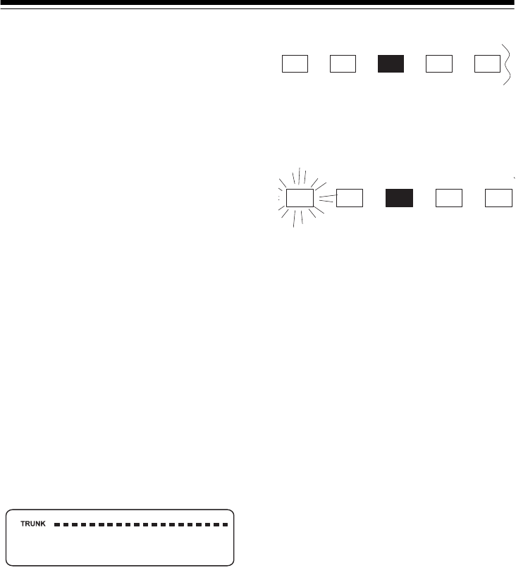
We recommend you set SQUELCH to
the position shown here before select-
ing a trunked bank.
Note: Change this setting as neces-
sary to get the best performance in
your area.
PROGRAMMING
TRUNKED
FREQUENCIES
Before you program your scanner to
track a trunked system, consider the
following:
• Valid trunked system frequencies
are as shown below.
Motorola system
:
935.0125–939.9875 MHz
(in 12.5 kHz steps)
851.0000–868.9875 MHz
(in 12.5 kHz steps)
406.0000–512.0000 MHz
(in 12.5 kHz steps)
137.0000–174.0000 MHz
(in 5 kHz steps)
Ericsson EDACS system
:
900.0000–956.000 MHz
(in 12.5 kHz steps)
806.0000–899.9875 MHz
(in 12.5 kHz steps, except
cellular frequencies)
406.0000–512.0000 MHz
(in 12.5 kHz steps)
137.0000–174.0000 MHz
(in 5 kHz steps)
• You can use any of your scanner’s
banks as either a trunk scanning
bank or conventional scanning
bank, but you cannot mix the two.
• The scanner only scans one
trunked system at a time. Al-
though you can store frequencies
for more than one trunked system
in one of your scanner’s banks,
the scanner only scans the fre-
quencies associated with the first
data channel it finds.
Before scanning a trunked system’s
transmissions, you must store the
trunked system’s frequencies in one of
the banks in your scanner by following
these steps.
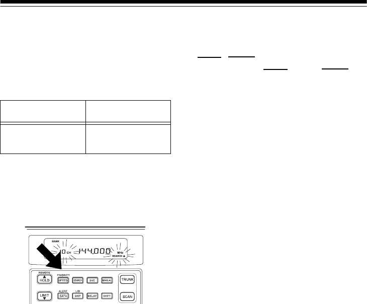
1. Set the scanner for conventional
scanning, then hold down TRUNK
until the scanner beeps twice.
BANK, TRUNK, and the bank
numbers flash.
2. Press a number key to select the
bank for the trunked system’s fre-
quencies. To select a bank
between 11 and 20, press SHIFT
then the number keys. The scan-
ner displays one of six system
types.
3. Use
▲ or ▼ to select the system
type, then press E.
20-432.fm Page 32 Friday, July 14, 2000 11:30 AM

33
4. Use the number keys to enter the
trunked system’s frequencies,
then press E.
Note: If you entered an invalid fre-
quency, the scanner beeps, the
channel number flashes and
Error appears. Press CLEAR to
clear the frequency, then repeat
Step 4.
5. Press either MANUAL or ▲ to
select the next channel in the
bank.
6. Repeat Steps 4 and 5 until all fre-
quencies have been entered.
SCANNING A TRUNKED
BANK
You can scan one trunked bank at a
time. Once you have stored frequen-
cies for a trunked system in one or
more of the 20 available banks, and
you are scanning non-trunked fre-
quencies, follow these steps to begin
trunk scanning.
1. Turn on the scanner and begin
scanning in conventional mode.
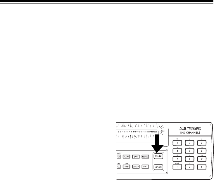
2. Press TRUNK. The indicators for
all banks that have been pro-
grammed with trunked frequen-
cies flash, and TRUNK and BANK
appear.
3. To see all banks programmed with
Motorola system frequencies,
press
▲. All banks programmed
with Motorola system frequencies
flash. To see all banks pro-
grammed with EDACS system fre-
quencies, press ▲ again. All
banks programmed with EDACS
system frequencies flash.
4. Use the number keys to activate
the trunked bank you want to
scan. appears under the
selected bank’s number.
5. Press SEARCH. As the scanner
searches for the trunk’s data
channel (the channel that con-
trols the trunk), SEARCH flashes.
When the scanner finds the data
channel, it begins trunk scanning.
If you entered all of the trunk’s fre-
quencies, you should be able to
follow conversations between
broadcasters even when they
change frequencies. IDs which
represent different service groups
appear.
Note: To see the bank currently in
use (for about 5 seconds), press
DATA.
6. To return to conventional scan-
ning, press TRUNK again.
You See Trunk System
E 1Motorola Type I,
800 MHz frequencies
Ed EDACS frequencies
E2 – UHF Motorola Type II,
UHF frequencies
E2 – Hi Motorola Type II,
VHF frequencies
E2 – 800 Motorola Type II,
800 MHz frequencies
E2 – 900 Motorola Type II,
900 MHz frequencies
20-432.fm Page 33 Friday, July 14, 2000 11:30 AM

34
Hint: While scanning, you will not
know exactly whom the talkgroup IDs
are assigned to until you listen awhile
or until you locate talkgroup ID lists in
frequency guides or on internet sites
such as www.trunkscanner.com. With-
in a few minutes, you can usually fig-
ure out if what you are listening to is a
police, fire, or emergency medical 2-
way radio user. Other talkgroup IDs
might take some time, but determining
whom each ID represents is half the
fun of trunk scanning!
Turning Banks On or Off
During Trunk Scanning
As in conventional scanning, you can
turn each channel-storage bank on
and off during trunk scanning. When
you turn off a bank, the scanner does
not scan any of the 50 channels in that
bank.
1. Press DATA. All active trunk bank
numbers appear.
2. Press the number key for the bank
you want to add or delete.
If the bank number is off, the scanner
does not scan any of the channels
within that bank.
Skipping the Trunked Bank
To skip to another trunked bank while
you are listening to a trunked bank,
hold down DATA.
Turning Status Bit Ignore
On or Off
You can set how your scanner works
with
status bits
(also called S-bits), let-
ting you control how the scanner inter-
prets and displays talkgroup IDs.
The last four bits of a Motorola Type II
talkgroup ID (a binary 16-bit code) are
the status bits. In some systems, sta-
tus bits identify special situations
(such as an emergency status).
Your scanner is preset to assume that
the status bits in a talkgroup ID are set
to 0 and ignores them. For example,
when the scanner receives the talk-
group ID 010111001110 0011, it
reads the ID as 010111001110 0000
and converts the first 12 bits of the ID
to 23776 (the talkgroup ID). However,
since the status bit value is 3 (0011
converted to decimal equals 3), the ID
is actually 23779.
If you are scanning a Motorola Type I
system and do not have a fleet map
for that system, you might have to turn
off status bit ignore in order to deter-
mine the proper fleet map.
Important: If you are scanning any
system other than a Motorola Type I
system, be sure status bit ignore is set
to ON or you will miss some transmis-
sions.
20-432.fm Page 34 Friday, July 14, 2000 11:30 AM

35
Follow these steps to turn status bit ig-
nore on or off.
1. Hold down SCAN until the current
status bit ignore setting (ON or
OFF) appears.
2. Press ▲ or ▼ to select ON or OFF,
then press E.
Identifying a Trunked
Frequency
To identify a trunked frequency, press
▼ when the scanner stops on a talk-
group ID. The trunked frequency brief-
ly flashes twice. To show the fre-
quency longer, hold down ▼. The
scanner beeps, then the trunked fre-
quency and talkgroup ID alternate.
Switching EDACS Format
The EDACS system uses two group
ID formats: Agency-Fleet-Subfleet
(AFS) and Decimal. If you use a list of
IDs shown in one format (AFS) and
the ID you want to receive is in the
other format (such as decimal, for ex-
ample), hold down SVC to switch to
the decimal format. The ID appears in
decimal format and E flashes.
EDACS ID Range Search
To make searching for EDACS IDs
faster, set a range for the Agency or
Fleet listings. Simply use the number
keys to enter the Agency or the Agen-
cy and the Fleet listing, then press
SEARCH. Note the following exam-
ples.
Example 1
Agency = 01
Press 0 1 . SEARCH.
01 --- appears during search.
Example 2
Agency = 01, Fleet = 01
Press 0 1 . 0 1 SEARCH.
01-01- appears during search.
To stop an ID range search, press
SEARCH again.
Using Trunk Scanning Scan
Delay
Many trunked systems have a period
of 2 or more seconds between a trans-
mission and a reply. You can pro-
gram a 5-second delay so the
scanner holds on an ID for 5 seconds
to wait for a reply. The scanner contin-
ues to monitor the frequency for 5 sec-
onds after the transmission stops
before resuming scanning.
Press DELAY to turn trunk scanning
scan delay on or off. DELAY appears
when trunk scanning scan delay is
set.
20-432.fm Page 35 Friday, July 14, 2000 11:30 AM

36
Note: If you consistently miss re-
sponses even with trunk scanning
scan delay set, you might need to
change the default system type or the
fleet map you are using. See “Scan-
ning Type I and Hybrid Trunked Sys-
tems” on Page 40.
Monitoring an Active ID
When the scanner stops on a trans-
mission, follow these steps to hold the
scanner on that transmission.
Note: You can also follow these steps
to hold on an ID while scanning a scan
list. See “Scan Lists” on Page 37.
1. Press HOLD. HOLD appears and
the scanner stays on the current
ID.
2. To continue trunk scanning, press
SEARCH.
Locking Out IDs
As with conventional scanning, it is
possible to lock out unwanted traffic.
This is particularly important in trunk-
ed systems because signals you can-
not listen to (such as water meters,
door alarms, traffic signals, and en-
crypted signals) are assigned IDs just
like other users. You can lock out up
to 100 IDs.
To lock out an ID, press L/O when the
ID appears. The ID is locked out, and
the next active ID appears.
Note: If you lock out an ID while
searching, it is also locked out of the
scan list(s). See “Scan Lists” on
Page 37.
Unlocking a Single ID
1. Hold down L/O until you hear two
short beeps.
2. Repeatedly press ▼ or ▲ to select
the ID you want to unlock.
3. Press L/O. The ID is unlocked and
the next locked ID appears.
4. Press SEARCH to resume the pre-
viously selected function.
Unlocking All IDs
Hold down L/O until you hear two short
beeps, then press E to unlock all the
IDs at once. The scanner beeps twice.
Note: When you unlock all the IDs,
the scan list mode appears. Press
SCAN to scan the IDs stored in your
scan lists or press SEARCH to resume
the previously selected function. For
more information about scan lists, see
“Scan Lists” on Page 37.
20-432.fm Page 36 Friday, July 14, 2000 11:30 AM
37
MONITORING IDS
You can use your scanner’s display to
monitor the frequencies in a trunked
system for activity. You cannot hear
conversations in this mode, but this is
an excellent way to determine which
talk groups are the most active.
To set the scanner to monitor IDs,
hold down SEARCH until the scanner
beeps twice. SEARCH flashes, and all
talk group IDs appear in succession.
To stop monitoring IDs, press
SEARCH again.
Note: When you monitor IDs, locked-
out IDs also appear.
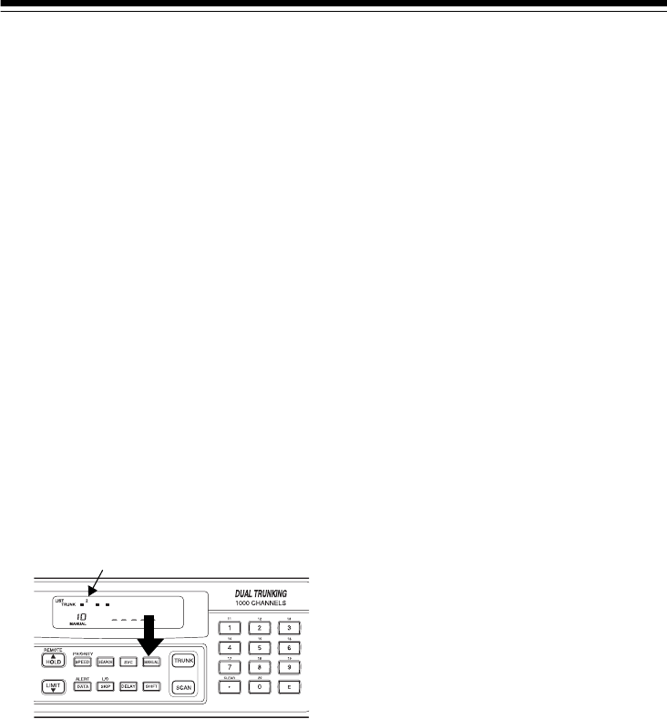
CHANNEL ACTIVITY
INDICATORS
Your scanner has 20 channel activity
indicators (bars). The bars show that
transmissions are being received on a
trunked system.
You can use the bars to tell how many
frequencies are being used and gen-
erally monitor how much communica-
tion traffic is occurring on a trunked
system.
• A bar that remains on steadily
even when there are no current
transmissions represents the fre-
quency being used as the data
channel.
• The bar that flashes when an ID
appears represents the frequency
being used by the radio you are
currently hearing.
• If a bar turns on but you do not
hear a conversation, the channel
is probably being used for a tele-
phone interconnect call or a pri-
vate call, or the indicator might be
a locked-out ID. Your scanner
does not monitor these types of
calls.
• If the scanner is holding on an ID
which is not active, the other bars
turn on and off as other groups
use the system
A bar appears for each frequency you
store in a trunking bank.
SCAN LISTS
When you program trunked frequen-
cies into a bank (see “Programming
Trunked Frequencies” on Page 32),
your scanner sets up 5 scan lists into
which you can store your favorite IDs.
Each list can contain up to 10 IDs, so
you can store a total of 50 IDs for each
trunk scanning bank (1000 IDs if you
use all banks as trunking banks).
20-432.fm Page 37 Friday, July 14, 2000 11:30 AM
38
Scan lists help you organize trunking
system users into categories. For ex-
ample, you might use List 1 for police
IDs, List 2 for fire department IDs, List
3 for emergency medical service IDs,
and so on. Once IDs are stored in
lists, you can scan them like you scan
conventional channels. You can pro-
gram IDs into scan lists manually, dur-
ing a search, or automatically.
Manually Storing IDs into
Scan Lists
1. Select the desired trunking bank
(see “Scanning a Trunked Bank”
on Page 33).
2. After the scanner begins trunk
scanning, press MANUAL. A scan
list number appears at the top of
the display, and a bar shows the
channel activity.
3. Repeatedly press ▲ or ▼ to select
the scan list location you want to
program.
4. Enter the Type II ID you want to
store, then press E.
Or, to enter a Type I ID:
a. Use the number keys to enter
the block number and the fleet
number, then press •.
b. Enter the subfleet number, then
press E.
Note: To clear a mistake while
entering an ID, press CLEAR, then
start over at Step 4.
Or, to enter an EDACS ID:
a. Use the number keys to enter
the agency number, then press •.
b. Enter the fleet number, then the
subfleet number, then press E.
5. Repeatedly press MANUAL or ▲
to select the next scan list location
you want to program. Then repeat
Step 4 to enter another ID.
Storing IDs into Scan Lists
While Searching
Follow these steps to select a scan list
location and store an ID during a
search.
1. When your scanner stops on an
ID you want to store, press PRI-
ORITY. The currently selected
scan list memory location flashes.
2. Press E to store the ID in the
selected scan list memory loca-
tion. Or, repeatedly press ▲ or ▼
to select another location, then
press
E.
3. Press SEARCH to resume search-
ing.
Scan List Number
20-432.fm Page 38 Friday, July 14, 2000 11:30 AM

39
Automatically Storing an ID in
a Scan List Location
To store an ID in the first available
scan list location during a search,
press
E at any time after the scanner
stops on that ID.
Or, follow these steps to store an ID in
a specific scan list location.
1. Press PRIORITY when the desired
ID appears.
2. Repeatedly press ▲ or ▼ to
choose a specific scan list loca-
tion.
3. Press
E.
Note: An ID you enter into a scan list
location automatically overwrites any
ID that is already stored in that loca-
tion.
To display a scan list location and
store an ID in that location during a
search, press PRIORITY to display the
current scan list location, then press E
when your scanner stops on an ID you
want to store.
Deleting a Stored ID
1. Press MANUAL.
2. Repeatedly press ▲ or ▼ to select
the scan list location (shown at the
top of the display) you want to
delete.
3. Press
0 then E.
SCANNING THE SCAN
LISTS
Press SCAN to begin scanning the
lists you have programmed. Id
SCAN scrolls on the display.
Note: If more than one of the scan IDs
you have stored do not work, Error
flashes twice and the scanner beeps
several times, then the scan list num-
bers appear at the top of the display.
To remove a scan list from active
scanning, use the number keys to en-
ter the scan list’s number. The scan
list indicator turns off, and the IDs in
that list are not scanned.
Note: You cannot remove all the scan
lists. One scan list must always be ac-
tive.
To restore a scan list to active scan-
ning, use the number keys to enter its
number again.
Press SEARCH to return to the previ-
ously selected function.
Priority ID Scanning
As in conventional scanning, you can
designate one ID in each scan list as a
priority ID.
To select an ID as a priority ID, hold
down PRIORITY for about 2 seconds
when the scanner stops on the ID. P
appears.
20-432.fm Page 39 Friday, July 14, 2000 11:30 AM

40
Press PRIORITY to turn on priority
scanning.
Note: Priority scanning does not work
if the ID is locked out.
SCANNING TYPE I AND
HYBRID TRUNKED
SYSTEMS
Your PRO-2052 is set to scan Type II
user IDs by default. When you scan
trunked frequencies, each Type II user
ID you see appears as an even num-
ber without a dash (such as 2160).
Your PRO-2052 can also scan Type I
trunked systems. Each Type I ID ap-
pears as a three- or four-digit number,
followed by a hyphen, followed by a
one- or two-digit number (such as
200-14).
If you notice a mix of odd- and even-
user IDs (such as 6477, 2160, 6481,
6144, and 1167), then you are proba-
bly monitoring either a Type I or hybrid
(a combination of Type I and Type II
user IDs) system. (See “Types of
Trunking Systems” on Page 30).
You might also notice that you are
missing responses when you hold on
an active ID. Unlike Type II systems,
Type I and hybrid systems require a
fleet map that sets specific fleet-
subfleet parameters. It is easy to se-
lect a fleet map to scan; what is not al-
ways easy is selecting or program-
ming a map that is being used in your
particular area.
When a Type I system is designed,
the address information for all its user
IDs is divided into 8 equal-size blocks,
numbered 0–7, and each block is as-
signed a size code. When you set up
your scanner to track a Type I system,
you must choose a size code for each
block. When you have chosen a size
code for all 8 blocks, you will have du-
plicated the
fleet map
for the system
you are tracking. If you have chosen
correctly, you will be able to track
transmissions in that system.
Each size code defines the number of
fleets, subfleets, and IDs each block
has. For example, you can see in the
following table that a size code of S4
has one fleet, which is divided into 16
separate subfleets, and it has a total
of 512 individual IDs.
Size Fleets Sub-
fleets IDs Block
Used
S0 Reserved block for Type II IDs
S1 128 4 16 1
S2 16 8 64 1
S3 8 8 128 1
S4 1 16 512 1
S5 64 4 32 1
S6 32 8 32 1
S7 32 4 64 1
S8 16 4 128 1
Size Fleets Sub-
fleets IDs Block
Used
S9 8 4 256 1
S10 4 8 256 1
20-432.fm Page 40 Friday, July 14, 2000 11:30 AM

41
Each ID in the block is unique. The
left-most digit is the block number in
the ID. The next two digits identify
which fleet is active, and the last dig-
it(s) (after the hyphen) identifies the
subfleet.
The size codes selected by a Type I
system designer depend on the spe-
cific needs of the system’s users.
Some organizations might want many
subfleets with only a few radios each,
while another organization might want
only a few subfleets, with many radios
each. To scan Type I systems, you
must select or program a fleet map
with the same size code assignments
as the trunked system. If you do this
accurately, you will track all the fleet
and subfleet combinations used by the
system. In other words, you will hear
complete communications while moni-
toring a trunked system.
Note:
www.trunkscanner.com
plans to
make preset fleet maps available as
they become known.
If you do not already know the size
codes used, you will have to guess
them. But since you do not have to fig-
ure out all the blocks at once, this is
not as hard as it seems. Select a size
code for a block, then press SEARCH.
Now listen to the communications. If
you decide you are receiving most of
the replies to the conversations with
IDs assigned to the block you just pro-
grammed, then you have probably se-
lected the right size code and can
work on the next block of the map.
There are 16 preset fleet maps to
choose from, and it is best to start with
these when setting up a Type I or hy-
brid trunk scanning bank. If none of
the following preset fleet maps allow
you to follow complete conversations,
then you probably need to program
your own fleet map (see “Program-
ming a Fleet Map” on Page 44).
S11 2 16 256 1
S12 1 16 1024 2
S13 1 16 2048 4
S14 1 16 4096 8
E1P1 E1P2
Block Size
Code Block Size
Code
0S110S4
1S111S4
2S112S4
3S113S4
4S114S4
5S115S4
6S116S4
7S117S4
E1P3 E1P4
Block Size
Code Block Size
Code
0S40S12
1S41(S12)
20-432.fm Page 41 Friday, July 14, 2000 11:30 AM

42
E1P3 E1P4
Block Size
Code Block Size
Code
2S42S4
3S43S4
4S44S4
5S45S4
6S126S4
7(S12) 7S4
E1P5 E1P6
Block Size
Code Block Size
Code
0S40S3
1S41S10
2S122S4
3(S12) 3S4
4S44S12
5S45(S12)
6S46S12
7S47(S12)
E1P7 E1P8
Block Size
Code Block Size
Code
0S100S1
1S101S1
2S112S2
3S43S2
4S44S3
E1P7 E1P8
Block Size
Code Block Size
Code
5S45S3
6S46S4
7S47S4
E1P9 E1P10
Block Size
Code Block Size
Code
0S40S0
1S41S0
2S02S0
3S03S0
4S04S0
5S05S0
6S06S4
7S07S4
E1P11 E1P12
Block Size
Code Block Size
Code
0S40S0
1S01S0
2S02S0
3S03S0
4S04S0
5S05S0
6S06S0
7S07S4
20-432.fm Page 42 Friday, July 14, 2000 11:30 AM
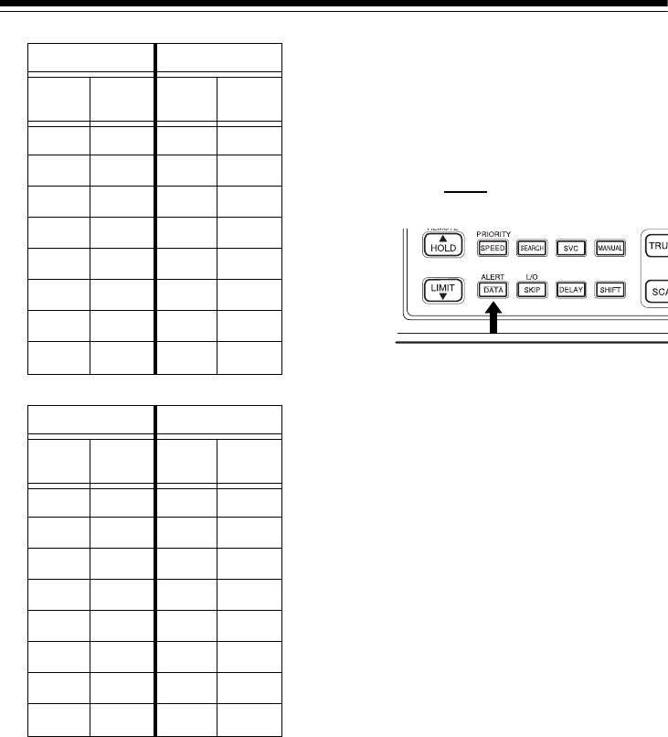
43
Selecting a Preset Fleet Map
1. Set the scanner for conventional
scanning, then hold down TRUNK
until the scanner beeps twice.
BANK, TRUNK, and the bank
numbers flash.
2. Press a number key to select the
bank where you want to store the
preset fleet map.
3. Repeatedly press ▲ or ▼ to select
E1 (Type I and hybrid), then press
E.
4. Press DATA.
5. Repeatedly press ▲ or ▼ to select
the name of the desired map
(such as E1P7), then press E.
The scanner then searches for trans-
missions using the preset map you
chose.
Note: When the scanner searches for
transmissions, you see Type I fleet
and subfleet IDs such as 100-12,
100-9, 000-12, or 400-8.
How do you know if the preset map
you selected is correct? Listen to see
if you are following complete conver-
sations. If not, try another preset map.
E1P13 E1P14
Block Size
Code Block Size
Code
0S30S4
1S31S3
2 S11 2 S10
3S43S4
4S44S4
5S05S4
6S06S12
7S07(S12)
E1P15 E1P16
Block Size
Code Block Size
Code
0S40S3
1S41S10
2S42S10
3 S11 3 S11
4S114S0
5S05S0
6 S12 6 S12
7(S12) 7(S12)
20-432.fm Page 43 Friday, July 14, 2000 11:30 AM

44
Programming a Fleet Map
1. Set the scanner for conventional
scanning, then hold down TRUNK
until the scanner beeps twice.
BANK, TRUNK, and the bank
numbers flash.
2. Press a number key to select the
bank where you programmed
Type I trunk frequencies.
3. Repeatedly press ▲ or ▼ until E1
appears, then press E.
4. Press DATA.
5. Repeatedly press ▲ or ▼ until
USr appears, then press DATA.
6. Repeatedly press ▲ or ▼ to select
the size code for the first block,
then press E. The next available
block appears.
7. Repeat Step 6 until you have
selected a size code for each
block you want to work with.
8. Press SEARCH. The scanner exits
the trunking programming mode,
tunes the data channel, then
begins to search using the map
you programmed.
Note: If you select size code S12,
S13, or S14, these restrictions apply:
• S12 can only be assigned to
Blocks 0, 2, 4, or 6.
• S13 can only be assigned to
Blocks 0 and 4.
• S14 can only be assigned to Block
0.
Since these size codes require multi-
ple blocks, you will be prompted for
the next available block when pro-
gramming a fleet map. For example, if
you assign Block 0 as an S12, the
scanner prompts you for b2, the next
block available, instead of b1. And if
you assign Block 0 as an S14, you
would not see another prompt be-
cause it uses all available blocks.
Programming a Hybrid
System
A hybrid system is simply a Type I
system with some of its blocks desig-
nated as Type II blocks. To program a
hybrid system, follow the steps listed
in “Programming a Fleet Map” on
Page 44. However, if you want a block
to be Type II, select size code S0 in
Step 6.
Programming the Base and
Offset Frequencies
To properly track Motorola VHF and
UHF trunked systems, you must pro-
gram the applicable
base
and
offset
frequencies for each system.
These settings can be found at
www.trunkscanner.com
and similar
frequency resources.
1. Set the scanner for conventional
scanning, then hold down TRUNK
until the scanner beeps twice.
2. Press the number key of the bank
where you want to store the base
frequency.
20-432.fm Page 44 Friday, July 14, 2000 11:30 AM

45
3. Repeatedly press ▲ or ▼ to select
E2-Hi or E2-UHF, then press E.
4. Press DATA. The preset base fre-
quency appears.
5. Enter a desired frequency, then
press
E.
6. Press DATA. The preset offset fre-
quency appears.
7. Enter the frequency using the
number keys according to the fol-
lowing guide, then press E:
• For Motorola Type II VHF, (E2-
Hi band) use 5 kHz steps
between 5 kHz–100 kHz.
• For Motorola Type II UHF, (E2-
UHF band) use 12.5 kHz steps
between 12.5 kHz–100 kHz.
Note: For example, if you pro-
gram 406.0250 as a trunked fre-
quency, the base and offset
frequencies are as follows:
• BASE: 406.0000 MHz, OFFSET:
12.5 kHz=Channel 2
• BASE: 406.0000 MHz, OFFSET:
25.0 kHz=Channel 1
8. Repeat the steps under “Program-
ming Trunked Frequencies” on
Page 32 to store the trunked sys-
tem’s frequencies in your scan-
ner’s banks.
Turning the Motorola
Disconnect Tone Detect
Function On/Off
While trunk scanning a Motorola sys-
tem, your scanner automatically tunes
to the data channel when it detects a
disconnect tone (a code that tells the
trunking system that the transmitter
has finished sending) on the voice
channel.
You can manually turn off this function
so the scanner does not tune to the
data channel under those conditions.
Use this feature to listen to weak
transmissions when conversations are
generally disconnected.
To turn the disconnect tone detect
function off, set the scanner to trunk
track then press SVC. The scanner
beeps and flashes for about 5
seconds.
Notes:
• To set the scanner so it remains
on the voice channel (even when
a disconnect tone is transmitted or
there is no signal at all) set
SQUELCH so you hear a hissing
noise.
• You cannot use the disconnect
tone detect function if you are pro-
gramming a trunking frequency or
a fleet map.
To set the scanner to automatically
tune to the data channel once again
when it detects a disconnect tone,
press
SVC. disappears.
DATA
DATA
20-432.fm Page 45 Friday, July 14, 2000 11:30 AM

46
PC REMOTE FUNCTION
Your scanner’s PC Remote function
lets you connect the scanner to a
computer then use the computer to
operate most of the scanner’s func-
tions, the same way as if you were us-
ing the keys on the scanner’s front
panel.
CONNECTING THE
SCANNER TO A
COMPUTER
Caution: Always turn off the computer
before connecting or disconnecting
your scanner. Otherwise you could
damage your computer or the scan-
ner.
To connect the scanner to your com-
puter, plug one end of an optional 9-
pin serial cable (available at your local
RadioShack store) into REMOTE on
the back of the scanner, then plug the
other end of the cable into your com-
puter’s serial port.
SETTING THE REMOTE
COMMUNICATION
FORMAT
To set the remote communication for-
mat so the scanner and computer can
communicate with each other, use
standard Windows communications
software (such as Modem Master or
Hyper Terminal, not supplied). See
your software’s documentation for
more information about operating it.
Software Settings
Use the following settings for the com-
munications software.
Scanner Settings
If necessary, follow these steps to
change your scanner’s BPS (bits per
second) rate.
Note: All other functions are inactive
while you set the BPS rate.
1. Hold down REMOTE and turn on
your scanner. The current BPS
rate appears.
2. If necessary, press ▲ or ▼ to
change the BPS rate.
3. Press E.
4. Turn off the scanner.
BPS rate 2400/4800/9600/
19200 BPS
Start/Stop bit 1 bit
Data Length 8 bit
Parity Check None
Code ASCII
Flow Control None
Return Code Carriage Return only
20-432.fm Page 46 Friday, July 14, 2000 11:30 AM

47
TURNING THE REMOTE
FUNCTION ON AND OFF
To turn the remote function on or off,
hold down REMOTE until the scanner
beeps. SFT flashes when the remote
function is turned on.
PC TO SCANNER
COMMANDS
Follow these steps to enter com-
mands to operate the scanner using
your computer.
1. Make sure your computer and
scanner are connected (see “Con-
necting the Scanner to a Com-
puter” on Page 46).
2. Run your computer’s communica-
tion software (see “Setting the
Remote Communication Format”
on Page 46).
3. Type a command listed in the fol-
lowing table then press Enter on
your computer’s keyboard.
For this operation Type this
command
Scan KEY00
Manual KEY01
Select channel 0–9 KEY02 #
where #
equals the
numeric
number
. (decimal point)/Clear KEY03
E (Enter) KEY04
Priority/scan speed KEY05
L/O/Skip KEY06
Hold/▲ (up)/Remote KEY07
Limit/▼ (down) KEY08
Search KEY09
SVC KEY10
Data/Alert KEY11
Delay KEY12
Trunk KEY13
Shift KEY14
20-432.fm Page 47 Friday, July 14, 2000 11:30 AM

48
PC TO SCANNER FUNCTIONS LIST
For the following functions, type the command then press Enter on your computer’s
keyboard.
Function Command
Check frequency stored in a channel # PM###
where ### equals the three-
digit channel number
Check if Delay is on DL
Clear the scanner’s memory AC
Important: This procedure
clears all the information
you have programmed into
the scanner. Use this proce-
dure only when you are
sure your scanner is not
working properly.
Check if Data Skip is on DS
Check if Lockout is on LO
Check the lower limit frequency for a limit
search LL
Set the lower limit frequency for a limit search LL########
where ######## equals the
frequency
Check the upper limit frequency for a limit
search LU
Set the upper limit frequency for a limit search LU########
where ######## equals the
frequency
Check the status of the current channel MA
Go to a specific channel MA###
where ### equals the three-
digit channel number
Check the scanner’s mode MD
20-432.fm Page 48 Friday, July 14, 2000 11:30 AM

49
Function Command
Check a bank’s priority channel number
Note: Enter a letter instead of the bank num-
ber. Example: “C” for bank 3.
PC n
Set a bank’s priority channel PC n###
where ### equals the three-
digit channel number
Check if Priority is on PR
Turn Priority on/off PRN/PRF
Add a frequency to a channel PM### ########
where ### equals the three-
digit channel number and
######## equals the fre-
quency
Check if Squelch Monitor is on QU
Turn Squelch Monitor on/off QUN/QUF
Check if Priority Monitor is on RI
Turn Priority Monitor on/off RIN/RIF
Check scanner modulation setting RM
Check which banks are active SB
Select banks for scanning SB x
where x equals a matching let-
ter equivalent to the bank you
want to scan. For example, to
scan bank 5, type E. Or, to
scan banks 3 and 7, type CG.
Check if Squelch is open SQ
Check for a frequency in search skip memory SS##
where ## equals the two-digit
memory number
Enter a frequency in search skip memory SS########
where ######## equals the
frequency
20-432.fm Page 49 Friday, July 14, 2000 11:30 AM

50
Function Command
Tune scanner to specific frequency RF########
where ######## equals the
frequency
Check a Trunk ID memory number IC
Set a Trunk ID memory number IC x
where x equals a matching let-
ter equivalent to the trunk ID
memory number
Check if Trunk ID Monitor is on ID
Turn Trunk ID Monitor on/off IDN/IDF
Check if Trunk ID number is in lockout mem-
ory IL###
Enter a Type 1 Trunk ID into lockout memory ILR xyy-zz
where x = a block number
yy = a fleet number
zz = a sub fleet number
Enter a Type 2 Trunk ID into lockout memory ILR nnnnnn
where nnnnnn equals an ID
number
Enter an EDACS Trunk ID into lockout mem-
ory ILR xx-yyz
where xx = an agency number
yy = a fleet number
z = a sub fleet number
Confirm EDACS ID mode AF
Change ID to AFS or decimal mode AFN/AFF
Check if S-Bit on BT
Turn S-Bit on/off BTN/BTF
Program fleet block on scanner FB & # %%
where & = a bank (A–T)
# = a fleet map block number
(0–7)
%% = a block size indicator
(00–14)
20-432.fm Page 50 Friday, July 14, 2000 11:30 AM

51
Function Command
Check if Frequency Identification active FI
Turn Frequency Identification on/off FIN/FIF
Check for Speaker Muting mode on/off MU?
Check Speaker Muting mode setting MU
Set Speaker Muting on/auto/off MUN/MUA/MUF
Confrim scan list priority ID location PI #
where # equals an ID location
number
Set scan list priority ID location PI @#
where @ equals an ID list num-
ber and # equals an ID location
number
Check EDACS ID range mode RG
Set EDACS ID range mode RG @
where @ equals a partial
EDACS ID. For example, a
partial EDACS ID could be 01-,
01-02.
Read scanner information SI
Check for active trunking banks TB
Check status of Tone Detection TD
Turn Tone Detection on/off TDN/TDF
Program Talk Group ID TG * @%& ##-$$
where * = a bank number
@ = an ID scan list
% = an ID location
& = a block number
## = a fleet number
$$ = a sub fleet number
Set trunking on bank of channels TR & # %%%%%%%% $$$$
where & = a bank (A–T)
# = a trunking type
% = a base frequency
$ = an offset step
20-432.fm Page 51 Friday, July 14, 2000 11:30 AM

52
SCANNER TO PC RESPONSES
The scanner sometimes returns responses via your computer and software. You
might see any of the following codes.
Code Meaning
NG Invalid command
ERR Command format error
ORER Overrun error
OK Command received
CXXX Channel number
FXXXXXXXX Frequency
TN Trunking frequency
TF Conventional fre-
quency
xN (Function) On
xF (Function) Off
20-432.fm Page 52 Friday, July 14, 2000 11:30 AM

53
SCANNER MODE CODES
The scanner sometimes returns information about the mode it is operating in via
your computer and software. You might see any of the following codes
Code For this Mode
00 Scan
01 Manual
02 Limit Search
03 Limit Search Hold
04 Service Scan
05 Service Scan Hold
06 Program
07 EDACS Program
08 System Program
09 ID Search
10 ID Search Hold
11 ID Scan
12 ID Manual
13 ID Lockout Review
14 Search Control Channel
15 EDACS ID Search
16 EDACS ID Hold
17 EDACS ID Scan
18 EDACS ID Manual
20-432.fm Page 53 Friday, July 14, 2000 11:30 AM

54
Code For this Mode
19 EDACS ID Lockout Review
20 EDACS Search Control Channel
21 VFO
20-432.fm Page 54 Friday, July 14, 2000 11:30 AM

55
A GENERAL GUIDE TO SCANNING
Reception of the frequencies covered by your scanner is mainly “line-of-sight.” That
means you usually cannot hear stations that are beyond the horizon.
GUIDE TO FREQUENCIES
National Weather Frequencies
Birdie Frequencies
Every scanner has birdie frequencies. Birdies are signals created inside the scan-
ner’s receiver. These operating frequencies might interfere with broadcasts on the
same frequencies. If you program one of these frequencies, you hear only noise on
that frequency. If the interference is not severe, you might be able to turn SQUELCH
clockwise to cut out the birdie. This scanner’s birdie frequencies (in MHz) are:
To find the birdies in your individual scanner, begin by disconnecting the antenna
and moving it away from the scanner. Make sure that no other nearby radio or TV
sets are turned on near the scanner. Use the search function and search every fre-
quency range from its lowest frequency to the highest. Occasionally, the searching
will stop as if it had found a signal, often without any sound. That is a birdie. Make a
list of all the birdies in your scanner for future reference.
162.400 162.475 162.525 162.425
162.500 162.550 162.450
171.25 406.7625 407.8125 413.175 413.225
20-432.fm Page 55 Friday, July 14, 2000 11:30 AM

56
GUIDE TO THE ACTION BANDS
Typical Band Usage (MHz)
VHF Band
Low Range 29.00–50.00
6-Meter Amateur 50.00–54.00
Aircraft 108.00–136.00
U.S. Government 137.00–144.00
2-Meter Amateur 144.00–148.00
High Range 148.00–174.00
FM-TV Audio Broadcast, Wide Band 174.00–216.00
New Mobile Narrow Band 220.00–222.00
1.3-Meter Amateur Band 222.00–225.00
Military Aircraft 225.00–287.80
UHF Band
Military Aircraft 311.00–384.00
U.S. Government 406.00–420.00
70-Centimeter Amateur 420.00–450.00
Low Range 450.00–470.00
FM-TV Audio Broadcast, Wide Band 470.00–512.00
Public Service 806.00–823.93
Conventional Systems 851.00–856.00
Conventional/Trunked Systems 856.00–861.00
Trunked Systems 861.00–866.00
Public Safety 866.00–868.93
High Range 896.11–902.00
33-Centimeter Amateur 902.00–928.00
Private Trunked 935.00–940.00
General Trunked 940.00–941.00
Fixed Services 941.00–944.00
Studio-to-Transmitter Broadcast Links 944.00–952.00
Private Fixed Services, Paging 952.00–960.00
Aeronautical Navigation 960.00–1240.00
23-Centimeter Amateur 1240.00–1300.00
20-432.fm Page 56 Friday, July 14, 2000 11:30 AM

57
Primary Usage
As a general rule, most of the radio activity is concentrated on the following fre-
quencies:
VHF Band
UHF Band
Note: Remote control stations and mobile units operate at 5 MHz higher than their
associated base stations and relay repeater units.
BAND ALLOCATION
To help decide which frequency ranges to scan, use the following listing of the typi-
cal services that use the frequencies your scanner receives. These frequencies are
subject to change, and might vary from area to area. For a more complete listing,
refer to the “Police Call Radio Guide including Fire and Emergency Services,” avail-
able at your local RadioShack store.
Activities Frequencies (MHz)
2-Meter Amateur Band 144.000–148.000
Government, Police, and Fire 153.785–155.980
Emergency Services 158.730–159.460
Railroad 160.000–161.900
Activities Frequencies (MHz)
70-Centimeter Amateur Band FM
Repeaters 440.000–450.000
Land-Mobile “Paired” Frequencies 450.000–470.000
Base Stations 451.025–454.950
Mobile Units 456.025–459.950
Repeater Units 460.025–464.975
Control Stations 465.025–469.975
20-432.fm Page 57 Friday, July 14, 2000 11:30 AM

58
Abbreviations Services
AIR . . . . . . . . . . . . . . . . . . . . . . . . . . . . . . . . . . . . . . . . . . . . . . . . . . . . . . . . . . . . . . . . Aircraft
BIFC . . . . . . . . . . . . . . . . . . . . . . . . . . . . . . . . . . . . . . . . . .Boise (ID) Interagency Fire Cache
BUS . . . . . . . . . . . . . . . . . . . . . . . . . . . . . . . . . . . . . . . . . . . . . . . . . . . . . . . . . . . . . .Business
CAP . . . . . . . . . . . . . . . . . . . . . . . . . . . . . . . . . . . . . . . . . . . . . . . . . . . . . . . . . .Civil Air Patrol
CB . . . . . . . . . . . . . . . . . . . . . . . . . . . . . . . . . . . . . . . . . . . . . . . . . . . . . . . . . . .Citizens Band
CCA . . . . . . . . . . . . . . . . . . . . . . . . . . . . . . . . . . . . . . . . . . . . . . . . . . . . . . . .Common Carrier
CSB . . . . . . . . . . . . . . . . . . . . . . . . . . . . . . . . . . . . . . . . . . . . . . . . . . . Conventional Systems
CTSB . . . . . . . . . . . . . . . . . . . . . . . . . . . . . . . . . . . . . . . . . . . Conventional/Trunked Systems
FIRE . . . . . . . . . . . . . . . . . . . . . . . . . . . . . . . . . . . . . . . . . . . . . . . . . . . . . . . . Fire Department
HAM . . . . . . . . . . . . . . . . . . . . . . . . . . . . . . . . . . . . . . . . . . . . . . . . . . . Amateur (Ham) Radio
GOVT . . . . . . . . . . . . . . . . . . . . . . . . . . . . . . . . . . . . . . . . . . . . . . . . . . . Federal Government
GMR. . . . . . . . . . . . . . . . . . . . . . . . . . . . . . . . . . . . . . . . . . . . . . . . . . . General Mobile Radio
GTR . . . . . . . . . . . . . . . . . . . . . . . . . . . . . . . . . . . . . . . . . . . . . . . . . . . . . . . General Trunked
IND . . . . . . . . . . . . . . . . . . . . . . . . . . . . . . . . . . . . . . . . . . . . . . . . . . . . . . . Industrial Services
(Manufacturing, Construction, Farming, Forest Products)
MAR . . . . . . . . . . . . . . . . . . . . . . . . . . . . . . . . . . . . . . . . . . . . . . . . . . .Military Amateur Radio
MARI . . . . . . . . . . . . . . . . . . . . . . . . . . . . . . . . . . . . . . . . . . . . . . . . . Maritime Limited Coast
(Coast Guard, Marine Telephone,
Shipboard Radio, Private Stations)
MARS. . . . . . . . . . . . . . . . . . . . . . . . . . . . . . . . . . . . . . . . . . . . Military Affiliate Radio System
MED . . . . . . . . . . . . . . . . . . . . . . . . . . . . . . . . . . . . . . . . . . . . . .Emergency/Medical Services
MIL . . . . . . . . . . . . . . . . . . . . . . . . . . . . . . . . . . . . . . . . . . . . . . . . . . . . . . . . . . . . U.S. Military
MOV . . . . . . . . . . . . . . . . . . . . . . . . . . . . . . . . . . . . . . . . . . . . . Motion Picture/Video Industry
NEW. . . . . . . . . . . . . . . . . . . . . . . . . . . . . . . . . . . . . . . . . . . . . . . . . . . . . New Mobile Narrow
NEWS. . . . . . . . . . . . . . . . . . . . . . . . . . . . . . . . . . . . . . . Relay Press (Newspaper Reporters)
OIL . . . . . . . . . . . . . . . . . . . . . . . . . . . . . . . . . . . . . . . . . . . . . . . . . . . . Oil/Petroleum Industry
POL . . . . . . . . . . . . . . . . . . . . . . . . . . . . . . . . . . . . . . . . . . . . . . . . . . . . . . Police Department
PUB . . . . . . . . . . . . . . . . . . . . . . . . . . . . . . . . . . . . . . . . . . . . . . . . . . . . . . . . .Public Services
(Public Safety, Local Government, Forestry Conservation)
PSB . . . . . . . . . . . . . . . . . . . . . . . . . . . . . . . . . . . . . . . . . . . . . . . . . . . . . . . . . . Public Safety
PTR . . . . . . . . . . . . . . . . . . . . . . . . . . . . . . . . . . . . . . . . . . . . . . . . . . . . . . . . Private Trunked
ROAD. . . . . . . . . . . . . . . . . . . . . . . . . . . . . . . . . . . . . . . . . . . .Road & Highway Maintenance
RTV . . . . . . . . . . . . . . . . . . . . . . . . . . . . . . . . . . . . . . . . Radio/TV Remote Broadcast Pickup
TAXI . . . . . . . . . . . . . . . . . . . . . . . . . . . . . . . . . . . . . . . . . . . . . . . . . . . . . . . . . . Taxi Services
TELB . . . . . . . . . . . . . . . . . . . . . . . . . . . . . . . . . . . . . . . . . . . . . . . . . . . . . .Mobile Telephone
(Aircraft, Radio Common Carrier, Landline Companies)
TELC . . . . . . . . . . . . . . . . . . . . . . . . . . . . . . . . . . . . . . . . . . . . . . . . . . . . . . Cordless Phones
TELM . . . . . . . . . . . . . . . . . . . . . . . . . . . . . . . . . . . . . . . . . . . . . . . . .Telephone Maintenance
TOW. . . . . . . . . . . . . . . . . . . . . . . . . . . . . . . . . . . . . . . . . . . . . . . . . . . . . . . . . . . .Tow Trucks
TRAN . . . . . . . . . . . . . . . . . . . . . . . . . . . . . . . . . . . . . . . . . . . . . . . . . Transportation Services
(Trucks, Tow Trucks, Buses, Railroad, Other)
TSB . . . . . . . . . . . . . . . . . . . . . . . . . . . . . . . . . . . . . . . . . . . . . . . . . . . . . . . Trunked Systems
TVn. . . . . . . . . . . . . . . . . . . . . . . . . . . . . . . . . . . . . . . . . . . . . . . . . . .FM-TV Audio Broadcast
USXX . . . . . . . . . . . . . . . . . . . . . . . . . . . . . . . . . . . . . . . . . . . . . . . . . .Government Classified
UTIL . . . . . . . . . . . . . . . . . . . . . . . . . . . . . . . . . . . . . . . . . . . . . . . . . . Power & Water Utilities
WTHR. . . . . . . . . . . . . . . . . . . . . . . . . . . . . . . . . . . . . . . . . . . . . . . . . . . . . . . . . . . . . Weather
20-432.fm Page 58 Friday, July 14, 2000 11:30 AM

59
HIGH FREQUENCY (HF) — (3 MHz–30 MHz)
10-Meter Amateur Band (28.0–29.7 MHz)
29.000–29.700 . . . . . . . . . . . . . . . . . . . . . . . . . . . . . . . . . . . . . . . . . . . . . . . . . . . . . . . . HAM
VERY HIGH FREQUENCY (VHF) — (30 MHz–300 MHz)
VHF Low Band (29.7–50 MHz—in 5 kHz steps)
29.700–29.790 . . . . . . . . . . . . . . . . . . . . . . . . . . . . . . . . . . . . . . . . . . . . . . . . . . . . . . . . . IND
29.900–30.550 . . . . . . . . . . . . . . . . . . . . . . . . . . . . . . . . . . . . . . . . . . . . . . . . . . . .GOVT, MIL
30.580–31.980 . . . . . . . . . . . . . . . . . . . . . . . . . . . . . . . . . . . . . . . . . . . . . . . . . . . . .IND, PUB
32.000–32.990 . . . . . . . . . . . . . . . . . . . . . . . . . . . . . . . . . . . . . . . . . . . . . . . . . . . .GOVT, MIL
33.020–33.980 . . . . . . . . . . . . . . . . . . . . . . . . . . . . . . . . . . . . . . . . . . . . . . . . BUS, IND, PUB
34.010–34.990 . . . . . . . . . . . . . . . . . . . . . . . . . . . . . . . . . . . . . . . . . . . . . . . . . . . .GOVT, MIL
35.020–35.980 . . . . . . . . . . . . . . . . . . . . . . . . . . . . . . . . . . . . . . . . . . BUS, PUB, IND, TELM
36.000–36.230 . . . . . . . . . . . . . . . . . . . . . . . . . . . . . . . . . . . . . . . . . . . . . . . . . . . .GOVT, MIL
36.230–36.990 . . . . . . . . . . . . . . . . . . . . . . . . . . . . . . . . . . . . . Oil Spill Cleanup, GOVT, MIL
37.020–37.980 . . . . . . . . . . . . . . . . . . . . . . . . . . . . . . . . . . . . . . . . . . . . . . . . . . . . .PUB, IND
38.000–39.000 . . . . . . . . . . . . . . . . . . . . . . . . . . . . . . . . . . . . . . . . . . . . . . . . . . . .GOVT, MIL
39.020–39.980 . . . . . . . . . . . . . . . . . . . . . . . . . . . . . . . . . . . . . . . . . . . . . . . . . . . . . . . . .PUB
40.000–42.000 . . . . . . . . . . . . . . . . . . . . . . . . . . . . . . . . . . . . . . . . . . . . . . GOVT, MIL, MARI
42.020–42.940 . . . . . . . . . . . . . . . . . . . . . . . . . . . . . . . . . . . . . . . . . . . . . . . . . . . . . . . . . POL
42.960–43.180 . . . . . . . . . . . . . . . . . . . . . . . . . . . . . . . . . . . . . . . . . . . . . . . . . . . . . . . . . IND
43.220–43.680 . . . . . . . . . . . . . . . . . . . . . . . . . . . . . . . . . . . . . . . . . . . . . . .TELM, IND, PUB
43.700–44.600 . . . . . . . . . . . . . . . . . . . . . . . . . . . . . . . . . . . . . . . . . . . . . . . . . . . . . . . .TRAN
44.620–46.580 . . . . . . . . . . . . . . . . . . . . . . . . . . . . . . . . . . . . . . . . . . . . . . . . . . . . POL, PUB
46.600–46.990 . . . . . . . . . . . . . . . . . . . . . . . . . . . . . . . . . . . . . . . . . . . . . . . . . . GOVT, TELC
47.020–47.400 . . . . . . . . . . . . . . . . . . . . . . . . . . . . . . . . . . . . . . . . . . . . . . . . . . . . . . . . .PUB
47.420. . . . . . . . . . . . . . . . . . . . . . . . . . . . . . . . . . . . . . . . . . . . . . . . . . . American Red Cross
47.440–49.580 . . . . . . . . . . . . . . . . . . . . . . . . . . . . . . . . . . . . . . . . . . . . . . . . . . . . .IND, PUB
49.610–49.990 . . . . . . . . . . . . . . . . . . . . . . . . . . . . . . . . . . . . . . . . . . . . . . . . . . . .MIL, TELC
6-Meter Amateur Band (50–54 MHz)
50.00–54.00 . . . . . . . . . . . . . . . . . . . . . . . . . . . . . . . . . . . . . . . . . . . . . . . . . . . . . . . . . . HAM
Aircraft Band (108–136 MHz)
108.000–121.490 . . . . . . . . . . . . . . . . . . . . . . . . . . . . . . . . . . . . . . . . . . . . . . . . . . . . . . . AIR
121.500. . . . . . . . . . . . . . . . . . . . . . . . . . . . . . . . . . . . . . . . . . . . . . . . . . . . . .AIR Emergency
121.510–136.000 . . . . . . . . . . . . . . . . . . . . . . . . . . . . . . . . . . . . . . . . . . . . . . . . . . . . . . . AIR
U.S. Government Band (137–144 MHz)
137.000–144.000 . . . . . . . . . . . . . . . . . . . . . . . . . . . . . . . . . . . . . . . . . . . . . . . . . GOVT, MIL
2-Meter Amateur Band (144–148 MHz)
144.000–148.000 . . . . . . . . . . . . . . . . . . . . . . . . . . . . . . . . . . . . . . . . . . . . . . . . . . . . . . HAM
20-432.fm Page 59 Friday, July 14, 2000 11:30 AM

60
VHF High Band (148–174 MHz)
148.050–150.345 . . . . . . . . . . . . . . . . . . . . . . . . . . . . . . . . . . . . . . . . . . . . . . CAP, MAR, MIL
150.775–150.790 . . . . . . . . . . . . . . . . . . . . . . . . . . . . . . . . . . . . . . . . . . . . . . . . . . . . . . .MED
150.815–150.980 . . . . . . . . . . . . . . . . . . . . . . . . . . . . . . . . . . . . . . . . TOW, Oil Spill Cleanup
150.995–151.475 . . . . . . . . . . . . . . . . . . . . . . . . . . . . . . . . . . . . . . . . . . . . . . . . .ROAD, POL
151.490–151.955 . . . . . . . . . . . . . . . . . . . . . . . . . . . . . . . . . . . . . . . . . . . . . . . . . . .IND, BUS
151.985 . . . . . . . . . . . . . . . . . . . . . . . . . . . . . . . . . . . . . . . . . . . . . . . . . . . . . . . . . . . . .TELM
152.0075 . . . . . . . . . . . . . . . . . . . . . . . . . . . . . . . . . . . . . . . . . . . . . . . . . . . . . . . . . . . . .MED
152.030–152.240 . . . . . . . . . . . . . . . . . . . . . . . . . . . . . . . . . . . . . . . . . . . . . . . . . . . . . . TELB
152.270–152.480 . . . . . . . . . . . . . . . . . . . . . . . . . . . . . . . . . . . . . . . . . . . . . . IND, TAXI, BUS
152.510–152.840 . . . . . . . . . . . . . . . . . . . . . . . . . . . . . . . . . . . . . . . . . . . . . . . . . . . . . . TELB
152.870–153.020 . . . . . . . . . . . . . . . . . . . . . . . . . . . . . . . . . . . . . . . . . . . . . . . . . . IND, MOV
153.035–153.725 . . . . . . . . . . . . . . . . . . . . . . . . . . . . . . . . . . . . . . . . . . . . . . .IND, OIL, UTIL
153.740–154.445 . . . . . . . . . . . . . . . . . . . . . . . . . . . . . . . . . . . . . . . . . . . . . . . . . .PUB, FIRE
154.490–154.570 . . . . . . . . . . . . . . . . . . . . . . . . . . . . . . . . . . . . . . . . . . . . . . . . . . .IND, BUS
154.585 . . . . . . . . . . . . . . . . . . . . . . . . . . . . . . . . . . . . . . . . . . . . . . . . . . . . .Oil Spill Cleanup
154.600–154.625 . . . . . . . . . . . . . . . . . . . . . . . . . . . . . . . . . . . . . . . . . . . . . . . . . . . . . . . BUS
154.655–156.240 . . . . . . . . . . . . . . . . . . . . . . . . . . . . . . . . . . . . . . . MED, ROAD, POL, PUB
156.255–157.425 . . . . . . . . . . . . . . . . . . . . . . . . . . . . . . . . . . . . . . . . . . . . . . . . . . OIL, MARI
157.450 . . . . . . . . . . . . . . . . . . . . . . . . . . . . . . . . . . . . . . . . . . . . . . . . . . . . . . . . . . . . . . MED
157.470–157.515 . . . . . . . . . . . . . . . . . . . . . . . . . . . . . . . . . . . . . . . . . . . . . . . . . . . . . . .TOW
157.530–157.725 . . . . . . . . . . . . . . . . . . . . . . . . . . . . . . . . . . . . . . . . . . . . . . . . . . .IND, TAXI
157.740 . . . . . . . . . . . . . . . . . . . . . . . . . . . . . . . . . . . . . . . . . . . . . . . . . . . . . . . . . . . . . . BUS
157.770–158.100 . . . . . . . . . . . . . . . . . . . . . . . . . . . . . . . . . . . . . . . . . . . . . . . . . . . . . . TELB
158.130–158.460 . . . . . . . . . . . . . . . . . . . . . . . . . . . . . . . . . . . . BUS, IND, OIL, TELM, UTIL
158.490–158.700 . . . . . . . . . . . . . . . . . . . . . . . . . . . . . . . . . . . . . . . . . . . . . . . . . . . . . . TELB
158.730–159.465 . . . . . . . . . . . . . . . . . . . . . . . . . . . . . . . . . . . . . . . . . . . . POL, PUB, ROAD
159.480 . . . . . . . . . . . . . . . . . . . . . . . . . . . . . . . . . . . . . . . . . . . . . . . . . . . . . . . . . . . . . . . OIL
159.495–161.565 . . . . . . . . . . . . . . . . . . . . . . . . . . . . . . . . . . . . . . . . . . . . . . . . . . . . . . TRAN
161.580–162.000 . . . . . . . . . . . . . . . . . . . . . . . . . . . . . . . . . . . . . . . . . . . . . . OIL, MARI, RTV
162.0125–162.35 . . . . . . . . . . . . . . . . . . . . . . . . . . . . . . . . . . . . . . . . . . . . GOVT, MIL, USXX
162.400–162.550 . . . . . . . . . . . . . . . . . . . . . . . . . . . . . . . . . . . . . . . . . . . . . . . . . . . . . WTHR
162.5625–162.6375 . . . . . . . . . . . . . . . . . . . . . . . . . . . . . . . . . . . . . . . . . .GOVT, MIL, USXX
162.6625 . . . . . . . . . . . . . . . . . . . . . . . . . . . . . . . . . . . . . . . . . . . . . . . . . . . . . . . . . . . . MED
162.6875–163.225 . . . . . . . . . . . . . . . . . . . . . . . . . . . . . . . . . . . . . . . . . . .GOVT, MIL, USXX
163.250 . . . . . . . . . . . . . . . . . . . . . . . . . . . . . . . . . . . . . . . . . . . . . . . . . . . . . . . . . . . . . MED
163.275–166.225 . . . . . . . . . . . . . . . . . . . . . . . . . . . . . . . . . . . . . . . . . . . .GOVT, MIL, USXX
166.250 . . . . . . . . . . . . . . . . . . . . . . . . . . . . . . . . . . . . . . . . . . . . . . . . . . . GOVT, RTV, FIRE
166.275–169.400 . . . . . . . . . . . . . . . . . . . . . . . . . . . . . . . . . . . . . . . . . . . . . . . . GOVT, BIFC
169.445–169.505 . . . . . . . . . . . . . . . . . . . . . . . . . . . . . . . . . . . . . . . . Wireless Mikes, GOVT
169.55–169.9875 . . . . . . . . . . . . . . . . . . . . . . . . . . . . . . . . . . . . . . . . . . . .GOVT, MIL, USXX
170.000–170.150 . . . . . . . . . . . . . . . . . . . . . . . . . . . . . . . . . . . . . . . BIFC, GOVT, RTV, FIRE
170.175–170.225 . . . . . . . . . . . . . . . . . . . . . . . . . . . . . . . . . . . . . . . . . . . . . . . . . . . . . GOVT
170.245–170.305 . . . . . . . . . . . . . . . . . . . . . . . . . . . . . . . . . . . . . . . . . . . . . . Wireless Mikes
170.350–170.400 . . . . . . . . . . . . . . . . . . . . . . . . . . . . . . . . . . . . . . . . . . . . . . . . . .GOVT, MIL
170.425–170.450 . . . . . . . . . . . . . . . . . . . . . . . . . . . . . . . . . . . . . . . . . . . . . . . . . . . . . . BIFC
170.475 . . . . . . . . . . . . . . . . . . . . . . . . . . . . . . . . . . . . . . . . . . . . . . . . . . . . . . . . . . . . . .PUB
170.4875–173.175 . . . . . . . . . . . . . . . . . . . . . . . . . . . . . . . . . . .GOVT, PUB, Wireless Mikes
173.225–173.5375 . . . . . . . . . . . . . . . . . . . . . . . . . . . . . . . . . . . . . . MOV, NEWS, UTIL, MIL
173.5625–173.5875 . . . . . . . . . . . . . . . . . . . . . . . . . . . . . . . . . . . . MIL Medical/Crash Crews
173.60–173.9875 . . . . . . . . . . . . . . . . . . . . . . . . . . . . . . . . . . . . . . . . . . . . . . . . . . . . . .GOVT
20-432.fm Page 60 Friday, July 14, 2000 11:30 AM

61
FM-TV Audio Broadcast, VHF Wide Band (174-216 MHz)
179.750. . . . . . . . . . . . . . . . . . . . . . . . . . . . . . . . . . . . . . . . . . . . . . . . . . . . . . . . . . . . . . . TV7
185.750. . . . . . . . . . . . . . . . . . . . . . . . . . . . . . . . . . . . . . . . . . . . . . . . . . . . . . . . . . . . . . . TV8
191.750. . . . . . . . . . . . . . . . . . . . . . . . . . . . . . . . . . . . . . . . . . . . . . . . . . . . . . . . . . . . . . . TV9
197.750. . . . . . . . . . . . . . . . . . . . . . . . . . . . . . . . . . . . . . . . . . . . . . . . . . . . . . . . . . . . . . TV10
203.750. . . . . . . . . . . . . . . . . . . . . . . . . . . . . . . . . . . . . . . . . . . . . . . . . . . . . . . . . . . . . . TV11
209.750. . . . . . . . . . . . . . . . . . . . . . . . . . . . . . . . . . . . . . . . . . . . . . . . . . . . . . . . . . . . . . TV12
215.750. . . . . . . . . . . . . . . . . . . . . . . . . . . . . . . . . . . . . . . . . . . . . . . . . . . . . . . . . . . . . . TV13
New Mobile Narrow Band (220-222 MHz)
220.000–222.000 . . . . . . . . . . . . . . . . . . . . . . . . . . . . . . . . . . . . . . . . . . . . . . . . . . . . . . NEW
1.3-Meter Amateur Band (222-225)
220.000–225.000 . . . . . . . . . . . . . . . . . . . . . . . . . . . . . . . . . . . . . . . . . . . . . . . . . . . . . . HAM
Military Aircraft Band (237.9-287.8 MHz)
237.900. . . . . . . . . . . . . . . . . . . . . . . . . . . . . . . . . . . . . . . . Coast Guard Search and Rescue
239.800. . . . . . . . . . . . . . . . . . . . . . . . . . . . . . . . . . . . . . . . . . . . . . . . . . . . . . . .FAA Weather
241.000. . . . . . . . . . . . . . . . . . . . . . . . . . . . . . . . . . . . . . . . . . . . . . . . . . . . . . . . . . . . . . Army
243.000. . . . . . . . . . . . . . . . . . . . . . . . . . . . . . . . . . . . . . . . . . . . . . . . . . . . . . . . . Emergency
255.400. . . . . . . . . . . . . . . . . . . . . . . . . . . . . . . . . . . . . . . . . . . . . . . . . . . .FAA Flight Service
257.800. . . . . . . . . . . . . . . . . . . . . . . . . . . . . . . . . . . . . . . . . . . . . . . . . . . . . . .Civilian towers
287.800. . . . . . . . . . . . . . . . . . . . . . . . . . . . . . . . . . . . . . . . . . . Coast Guard Air/Sea Rescue
ULTRA HIGH FREQUENCY (UHF) — (300 MHz–3 GHz)
Military Aircraft Band (319.1-383.9 MHz)
319.100. . . . . . . . . . . . . . . . . . . . . . . . . . . . . . . . . . . . . . . . . . . . . . . . . . . .FAA Traffic control
321.000-336.600. . . . . . . . . . . . . . . . . . . . . . . . . . . . . . . . . . . . . . . . . . . . . . . . . . . . Air Force
342.500-344.600. . . . . . . . . . . . . . . . . . . . . . . . . . . . . . . . . . . . . . . . . . . . . . . . .FAA Weather
346.400-364.200. . . . . . . . . . . . . . . . . . . . . . . . . . . . . . . . . . . . . . . . . . . . . Air Traffic Control
381.800-383.900. . . . . . . . . . . . . . . . . . . . . . . . . . . . . . . . . . . . . . . . . . . . . . . . . Coast Guard
U. S. Government Band (406–420 MHz)
406.125–419.975 . . . . . . . . . . . . . . . . . . . . . . . . . . . . . . . . . . . . . . . . . . . . . . . .GOVT, USXX
70-Centimeter Amateur Band (420–450 MHz)
420.000–450.000 . . . . . . . . . . . . . . . . . . . . . . . . . . . . . . . . . . . . . . . . . . . . . . . . . . . . . . HAM
Low Band (450–470 MHz)
450.050–450.925 . . . . . . . . . . . . . . . . . . . . . . . . . . . . . . . . . . . . . . . . . . . . . . . . . . . . . . . RTV
451.025–452.025 . . . . . . . . . . . . . . . . . . . . . . . . . . . . . . . . . . . . . . . . .IND, OIL, TELM, UTIL
452.0375–453.00 . . . . . . . . . . . . . . . . . . . . . . . . . . . . . . . . . .IND, TAXI, TRAN TOW, NEWS
453.0125–454.000 . . . . . . . . . . . . . . . . . . . . . . . . . . . . . . . . . . . . . . . . . . . . . . . . . .PUB, OIL
454.025–454.975 . . . . . . . . . . . . . . . . . . . . . . . . . . . . . . . . . . . . . . . . . . . . . . . . . . . . . . TELB
455.050–455.925 . . . . . . . . . . . . . . . . . . . . . . . . . . . . . . . . . . . . . . . . . . . . . . . . . . . . . . . RTV
457.525–457.600 . . . . . . . . . . . . . . . . . . . . . . . . . . . . . . . . . . . . . . . . . . . . . . . . . . . . . . .BUS
458.025–458.175 . . . . . . . . . . . . . . . . . . . . . . . . . . . . . . . . . . . . . . . . . . . . . . . . . . . . . . MED
460.0125–460.6375 . . . . . . . . . . . . . . . . . . . . . . . . . . . . . . . . . . . . . . . . . . . FIRE, POL, PUB
460.650–462.175 . . . . . . . . . . . . . . . . . . . . . . . . . . . . . . . . . . . . . . . . . . . . . . . . . . . . . . BUS
20-432.fm Page 61 Friday, July 14, 2000 11:30 AM

62
462.1875–462.450 . . . . . . . . . . . . . . . . . . . . . . . . . . . . . . . . . . . . . . . . . . . . . . . . . . BUS, IND
462.4625–462.525 . . . . . . . . . . . . . . . . . . . . . . . . . . . . . . . . . . . . . . . . IND, OIL, TELM, UTIL
462.550–462.925 . . . . . . . . . . . . . . . . . . . . . . . . . . . . . . . . . . . . . . . . . . . . . . . . . .GMR, BUS
462.9375–463.1875 . . . . . . . . . . . . . . . . . . . . . . . . . . . . . . . . . . . . . . . . . . . . . . . . . . . . .MED
463.200–467.925 . . . . . . . . . . . . . . . . . . . . . . . . . . . . . . . . . . . . . . . . . . . . . . . . . . . . . . . BUS
FM-TV Audio Broadcast, UHF Wide Band (470–512 MHz)
(Channels 14 through 20 in 6 MHz steps)
475.750 . . . . . . . . . . . . . . . . . . . . . . . . . . . . . . . . . . . . . . . . . . . . . . . . . . . . . . . . Channel 14
481.750 . . . . . . . . . . . . . . . . . . . . . . . . . . . . . . . . . . . . . . . . . . . . . . . . . . . . . . . . Channel 15
487.750 . . . . . . . . . . . . . . . . . . . . . . . . . . . . . . . . . . . . . . . . . . . . . . . . . . . . . . . . Channel 16
511.750. . . . . . . . . . . . . . . . . . . . . . . . . . . . . . . . . . . . . . . . . . . . . . . . . . . . . . . . . Channel 20
Note: Some cities use the 470–512 MHz band for land/mobile service.
Conventional Systems Band – Locally Assigned
851.0125–855.9875 . . . . . . . . . . . . . . . . . . . . . . . . . . . . . . . . . . . . . . . . . . . . . . . . . . . . . CSB
Conventional/Trunked Systems Band – Locally Assigned
856.0125–860.9875 . . . . . . . . . . . . . . . . . . . . . . . . . . . . . . . . . . . . . . . . . . . . . . . . . . . . CTSB
Trunked Systems Band – Locally Assigned
861.0125–865.9875 . . . . . . . . . . . . . . . . . . . . . . . . . . . . . . . . . . . . . . . . . . . . . . . . . . . . . TSB
Public Safety Band – Locally Assigned
866.0125–868.9875 . . . . . . . . . . . . . . . . . . . . . . . . . . . . . . . . . . . . . . . . . . . . . . . . . . . . . PSB
33-Centimeter Amateur Band (902–928 MHz)
902.0000–928.0000 . . . . . . . . . . . . . . . . . . . . . . . . . . . . . . . . . . . . . . . . . . . . . . . . . . . . .HAM
Private Trunked
935.0125–939.9875 . . . . . . . . . . . . . . . . . . . . . . . . . . . . . . . . . . . . . . . . . . . . . . . . . . . . . PTR
General Trunked
940.0125–940.9875 . . . . . . . . . . . . . . . . . . . . . . . . . . . . . . . . . . . . . . . . . . . . . . . . . . . . . GTR
20-432.fm Page 62 Friday, July 14, 2000 11:30 AM

63
FREQUENCY CONVERSION
The tuning location of a station can be expressed in frequency (kHz or MHz) or in
wavelength (meters). The following information can help you make the necessary
conversions.
1 MHz (million) = 1,000 kHz (thousand)
• To convert MHz to kHz, multiply the number of megahertz by 1,000:
9.62 (MHz) × 1000 = 9620 kHz
• To convert from kHz to MHz, divide the number of kilohertz by 1,000:
2780 (kHz) ÷ 1000 = 2.780 MHz
• To convert MHz to meters, divide 300 by the number of megahertz:
300 ÷ 7.1 MHz = 42.25 meters
20-432.fm Page 63 Friday, July 14, 2000 11:30 AM

64
TROUBLESHOOTING
If your scanner is not working as it should, these suggestions might help you elimi-
nate the problem. If the scanner still does not operate properly, take it to your local
RadioShack store for assistance.
PROBLEM POSSIBLE CAUSE REMEDY
Scanner is on but will not
scan. SQUELCH is not correctly
adjusted. Adjust SQUELCH clock-
wise.
Only one channel or no
channels are stored. Store frequencies into more
than one channel.
Scanner is totally inopera-
tive. No power. Make sure the scanner is
plugged into a working AC
or DC outlet.
The AC or DC adapter is not
connected. Be sure the adapter’s barrel
plug is fully inserted into the
DC 12V jack.
The scanner must be reset. Reset the scanner (see
“Resetting the Scanner” on
Page 66).
Poor or no reception An antenna is not con-
nected or connected incor-
rectly.
Make sure an antenna is
connected to the scanner.
Error appears. Programming error. Reprogram the frequency
correctly, including the deci-
mal point.
In the scan mode, the scan-
ner locks on frequencies
that have an unclear trans-
mission.
Programmed frequencies
are the same as “birdie” fre-
quencies.
Avoid programming fre-
quencies listed under
“Birdie Frequencies” on
Page 55 or only listen to
them manually.
Scanner will not track a
trunked system. The transmission might not
use a system that can be
tracked by your scanner.
Scan another transmission.
The data frequency is miss-
ing. Find the data frequency
(see “Programming Trunked
Frequencies” on Page 32).
20-432.fm Page 64 Friday, July 14, 2000 11:30 AM

65
Scanner will not track a
trunked system
(continued)
The system you are trying
to track is a Type I System,
and the scanner is set to
scan Type II systems.
Set the scanner to receive
Type I trunked frequencies.
See “Scanning Type I and
Hybrid Trunked Systems”
on Page 40.
Scanner will not stop while
scanning a scan list The IDs you have stored
are not active. Scan another transmission.
Scanner will not acquire a
data channel Squelch is not correctly
adjusted. See “Setting Squelch for the
Trunk Scanning Mode” on
Page 31.
The frequency used for the
data channel is missing. Add the frequency used for
the data channel to the fre-
quency list. See “Program-
ming Trunked Frequencies”
on Page 32.
Missing replies to conversa-
tions The system you are trying
to track is a Type I system,
and the scanner is set to
scan Type II systems.
Set the scanner to receive
Type I trunked frequencies.
See “Scanning Type I and
Hybrid Trunked Systems”
on Page 40.
The selected fleet map is
incorrect. Try another preset fleet map
or program your own fleet
map. See “Scanning Type I
and Hybrid Trunked Sys-
tems” on Page 40.
Not all of the trunk’s fre-
quencies have been
entered.
Enter all of the trunk’s fre-
quencies.
Channel activity indicators
are lighting but no sound is
heard.
The transmission might be a
private or telephone inter-
connect call. The scanner
does not scan these types
of transmissions.
Scan for another transmis-
sion.
The ID is locked out. Unlock the ID (see “Unlock-
ing a Single ID” on Page 36
or “Unlocking All IDs” on
Page 36).
PROBLEM POSSIBLE CAUSE REMEDY
20-432.fm Page 65 Friday, July 14, 2000 11:30 AM
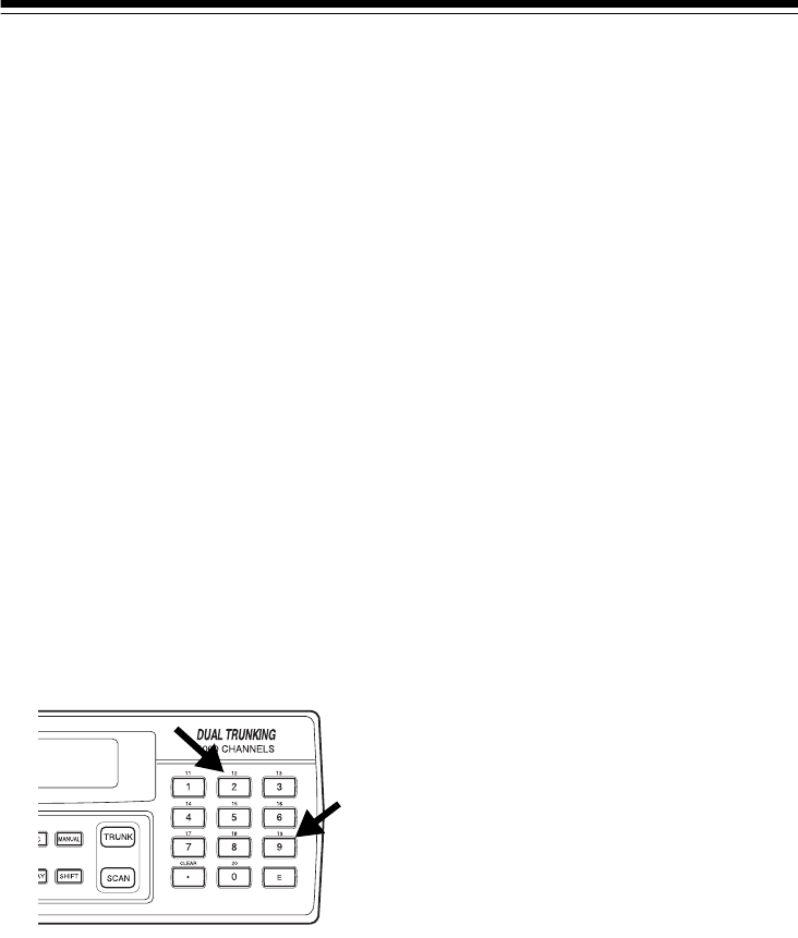
66
RESETTING THE
SCANNER
You might need to reset the scanner
if:
• the scanner’s display locks up.
• the scanner does not work prop-
erly after you connect power.
• the scanner is dropped or sub-
jected to a physical or electrical
shock.
Caution:
This procedure clears all the
information you have programmed
into the scanner. Use this procedure
only when you are sure your scanner
is not working properly.
To reset the scanner, turn it off. Then,
while you hold down 2 and 9, turn on
the scanner. CLEAr appears for
about 5 seconds while the scanner re-
sets.
Caution: Do not turn off the scanner
while it is resetting.
20-432.fm Page 66 Friday, July 14, 2000 11:30 AM

67
CARE AND MAINTENANCE
Your RadioShack PRO-2052 1000-Channel Dual Trunking TrunkTracker Home
Scanner is an example of superior design and craftsmanship. The following sug-
gestions will help you care for your scanner so you can enjoy it for years.
Keep the scanner dry. If it gets wet, wipe it dry immediately. Liquids
might contain minerals that can corrode the electronic circuits.
Use and store the scanner only in normal temperature environments.
Temperature extremes can shorten the life of electronic devices and
distort or melt plastic parts.
Keep the scanner away from dust and dirt, which can cause premature
wear of parts.
Handle the scanner gently and carefully. Dropping it can damage cir-
cuit boards and cases and can cause the scanner to work improperly.
Wipe the scanner with a damp cloth occasionally to keep it looking
new. Do not use harsh chemicals, cleaning solvents, or strong deter-
gents to clean the scanner.
Modifying or tampering with the scanner’s internal components can cause a mal-
function and might invalidate its warranty and void your FCC authorization to oper-
ate it. If your scanner is not performing as it should, take it to your local
RadioShack store for assistance.
20-432.fm Page 67 Friday, July 14, 2000 11:30 AM

68
SPECIFICATIONS
Frequency Coverage (MHz):
10 Meter Amateur Radio ...................................... 29.000–29.6950 (in 5 kHz steps)
VHF Lo ............................................................... 29.7000–49.9950 (in 5 kHz steps)
6 Meter Amateur Radio ...................................... 50.0000–54.0000 (in 5 kHz steps)
Aircraft ....................................................... 108.0000–136.9750 (in 12.5 kHz steps)
Government ................................................... 137.0000–143.9950 (in 5 kHz steps)
2 Meter Amateur Radio .................................... 144.000–147.9950 (in 5 kHz steps)
VHF Hi ........................................................... 148.0000–174.0000 (in 5 kHz steps)
VHF TV ........................................................... 179.7500-215.7500 (in 6MHz steps)
1 Meter Amateur Radio ...................................... 216.000-224.995 (in 5 kHz steps)
VHF Aircraft ................................................ 225.000-399.9875 (in 12.5 kHz steps)
Amateur Radio/Government ..................... 400.0000–419.9875 (in 12.5 kHz steps)
70-cm Amateur Radio ............................... 420.0000–449.9875 (in 12.5 kHz steps)
UHF Standard ........................................... 450.0000–469.9875 (in 12.5 kHz steps)
UHF “T” ..................................................... 470.0000–512.0000 (in 12.5 kHz steps)
Public Service ........................................... 806.0000–823.9375 (in 12.5 kHz steps)
Public Service/Trunking Repeater ............. 851.0000–868.9875 (in 12.5 kHz steps)
Public Service ........................................... 896.1125–956.0000 (in 12.5 kHz steps)
25-cm Amateur Radio ........................... 1240.0000-1300.0000 (in 12.5 kHz steps)
Channels of Operation .................... Any 1000 channels in any band combinations
(50 channels × 20 banks), 50 search skip memories, and
20 service search skip memories
Sensitivity (S+N)/N=20 dB:
29–54 MHz .............................................................................................. 0.5 µV
108–136.975 MHz ................................................................................... 1.5 µV
137–174 MHz .......................................................................................... 0.5 µV
179.75-215.75 MHz ................................................................................. 3.0 µV
216-224.995 MHz .................................................................................... 0.5 µV
225-399.9875 MHz .................................................................................. 1.5 µV
400–512 MHz .......................................................................................... 0.4 µV
806–956 MHz .......................................................................................... 1.0 µV
1240-1300 MHz ....................................................................................... 2.0 µV
Spurious Rejection (@40.85 MHz) ................................................................ 60 dB
Selectivity:
±10 kHz ................................................................................................... –6 dB
±15 kHz ................................................................................................. –50 dB
IF Rejection (@162.4 MHz) ........................................................................... 80 dB
20-432.fm Page 68 Friday, July 14, 2000 11:30 AM

69
Search Speed:
Normal .............................................................................100 Steps/Sec (Max)
Hyper .......................................... 300 Steps/Sec (Max) (only 5 kHz step band)
Scan Speed ................................................................ 50 Channels/Sec. (Nominal)
Priority Sampling ..................................................................................... 2 Seconds
Delay Time ............................................................................................. 2 Seconds
IF Frequencies:
1st IF ......................................... 29–310.9875 MHz: 380.6050–380.7000 MHz
311–512 MHz: 254.3125–254.4000 MHz
806–956 MHz: 380.7000–380.7875 MHz
1240–1300 MHz: 380.7000-380.7875 MHz
2nd IF ............................................................... 179.75–215.75 MHz: 10.7 MHz
Other Bands 10.85 MHz
3rd IF .................................................................................................... 450 kHz
Squelch Sensitivity:
Threshold ............................................................................... Less than 0.6 µV
Tight ............................................................. VHF Lo, Hi, UHF (S + N)/N 25 dB
Aircraft (S + N)/N 15 dB
Antenna Impedance ................................................................................... 50 ohms
Audio Power .................................................................................. 1.1 W Maximum
Built-In Speaker .......................................................... 21/4 Inches (57 mm), 8 ohms
Operating Temperature ....................................................................–10 C to + 50 C
Power Requirements:
AC Adapter ....................................................................................12 Volts DC
DC Adapter ................................................................................... 12 Volts DC
Current Drain:
At Squelched ..........................................................................................240 mA
At Full Output .........................................................................................440 mA
Dimensions (HWD) ........................................................... 23/4 × 81/16 × 711/16 Inches
(70 × 205 × 195 mm)
Weight ........................................................................................................ 26.5 oz.
(750 g)
Specifications are typical; individual units might vary. Specifications are subject to
change and improvement without notice.
20-432.fm Page 69 Friday, July 14, 2000 11:30 AM

70
NOTES
20-432.fm Page 70 Friday, July 14, 2000 11:30 AM

71
20-432.fm Page 71 Friday, July 14, 2000 11:30 AM

RadioShack
A Division of Tandy Corporation
Fort Worth, Texas 76102
UBZZ01307ZZ
09A99 Printed in the Philippines
Limited One-Year Warranty
This product is warranted by RadioShack against manufacturing defects in material and workman-
ship under normal use for one (1) year from the date of purchase from RadioShack company-owned
stores and authorized RadioShack franchisees and dealers. EXCEPT AS PROVIDED HEREIN, Ra-
dioShack MAKES NO EXPRESS WARRANTIES AND ANY IMPLIED WARRANTIES, INCLUDING
THOSE OF MERCHANTABILITY AND FITNESS FOR A PARTICULAR PURPOSE, ARE LIMITED
IN DURATION TO THE DURATION OF THE WRITTEN LIMITED WARRANTIES CONTAINED
HEREIN. EXCEPT AS PROVIDED HEREIN, RadioShack SHALL HAVE NO LIABILITY OR RE-
SPONSIBILITY TO CUSTOMER OR ANY OTHER PERSON OR ENTITY WITH RESPECT TO ANY
LIABILITY, LOSS OR DAMAGE CAUSED DIRECTLY OR INDIRECTLY BY USE OR PERFOR-
MANCE OF THE PRODUCT OR ARISING OUT OF ANY BREACH OF THIS WARRANTY, IN-
CLUDING, BUT NOT LIMITED TO, ANY DAMAGES RESULTING FROM INCONVENIENCE, LOSS
OF TIME, DATA, PROPERTY, REVENUE, OR PROFIT OR ANY INDIRECT, SPECIAL, INCIDEN-
TAL, OR CONSEQUENTIAL DAMAGES, EVEN IF RadioShack HAS BEEN ADVISED OF THE
POSSIBILITY OF SUCH DAMAGES.
Some states do not allow the limitations on how long an implied warranty lasts or the exclusion of in-
cidental or consequential damages, so the above limitations or exclusions may not apply to you.
In the event of a product defect during the warranty period, take the product and the RadioShack
sales receipt as proof of purchase date to any RadioShack store. RadioShack will, at its option, un-
less otherwise provided by law: (a) correct the defect by product repair without charge for parts and
labor; (b) replace the product with one of the same or similar design; or (c) refund the purchase
price. All replaced parts and products, and products on which a refund is made, become the prop-
erty of RadioShack. New or reconditioned parts and products may be used in the performance of
warranty service. Repaired or replaced parts and products are warranted for the remainder of the
original warranty period. You will be charged for repair or replacement of the product made after the
expiration of the warranty period.
This warranty does not cover: (a) damage or failure caused by or attributable to acts of God, abuse,
accident, misuse, improper or abnormal usage, failure to follow instructions, improper installation or
maintenance, alteration, lightning or other incidence of excess voltage or current; (b) any repairs
other than those provided by a RadioShack Authorized Service Facility; (c) consumables such as
fuses or batteries; (d) cosmetic damage; (e) transportation, shipping or insurance costs; or (f) costs
of product removal, installation, set-up service adjustment or reinstallation.
This warranty gives you specific legal rights, and you may also have other rights which vary from
state to state.
RadioShack Customer Relations, 200 Taylor Street, 6th Floor, Fort Worth, TX 76102
We Service What We Sell
04/99
20-432.fm Page 72 Friday, July 14, 2000 11:30 AM
