Radio Solutions SB400M1A UHF PART 90 INDUSTRIAL SIGNAL BOOSTER User Manual
Radio Solutions, Inc UHF PART 90 INDUSTRIAL SIGNAL BOOSTER
User Manual

© 2016 Radio Solutions, Inc. Norwell, MA - USA
1
USER MANUAL
SB400M1A
Band Selective Class B Signal Booster
Bi-Directional Amplifier (BDA)
**Patents Pending** V1.1.0
© 2016 Radio Solutions, Inc. Norwell, MA - USA
2
FCC ID: 2AHVPSB400M1A
Unauthorized Changes to Equipment - Changes or Modifications not expressly approved by the
manufacturer responsible for compliance could void the user’s authority to operate the equipment
FCC RF Exposure Limits - This unit complies with FCC RF exposure limits for an uncontrolled
environment. To comply with FCC RF exposure limit requirements antennas must be operated at a
minimum distance of 51cm or 20” between the radiator and any person’s body. This assumes 5W ERP
(=8.2W EIRP) with 20% power margin.
§ 90.219 (d) Class B broadband signal boosters are permitted to be used only in confined or indoor
areas such as buildings, tunnels, underground areas, etc., or in remote areas, i.e., areas where there
is little or no risk of interference to other users.
§ 90.219 (e) The licensee is given authority to operate signal boosters without separate authorization
from the Commission. Certificated equipment must be employed and the licensee must ensure that all
applicable rule requirements are met. (f) Licensees employing either Class A narrowband or Class B
broadband signal boosters as defined in §90.7 are responsible for correcting any harmful
interference that the equipment may cause to other systems. Normal co-channel transmissions
will not be considered as harmful interference. Licensees will be required to resolve interference
problems pursuant to §90.173(b).
ERP POWER LIMIT: FCC regulations limit signal booster ERP (Effective Radiated Power) to 5W.
Effective radiated power is calculated as follows: 1.59W - (CABLE LOSSES) – (CONNECTOR AND
SPLITTER LOSSES) - (ANY OTHER SYSTEM LOSSES) + (ANTENNA GAIN), where the 1.59W figure is
the maximum output power of the signal booster @ 32dBm. If a high gain antennas are used,
such as a directional Yagi antenna, please reduce the maximum output power of the signal
booster so that the ERP (Effective Radiated Power) does not exceed the 5W limit.
https://signalboosters.fcc.gov/signal-boosters/
WARNING. This is NOT a CONSUMER device. It is designed for installation
by FCC LICENSEES and QUALIFIED INSTALLERS. You MUST have an FCC
LICENSE or express consent of an FCC Licensee to operate this device. You
MUST register Class B signal boosters (as defined in 47 CFR 90.219) online
at www.fcc.gov/signal-boosters/registration. Unauthorized use may result
in significant forfeiture penalties, including penalties in excess of $100,000
for each continuing violation.
Part 90 Signal Boosters THIS IS A 90.219 CLASS B DEVICE
For Class A or Class B Unintentional Radiators:
This device complies with part 15 of the FCC Rules. Operation is subject to the following two conditions:
(1) This device may not cause harmful interference, and
(2) This device must accept any interference received, that may cause undesired operation.

© 2016 Radio Solutions, Inc. Norwell, MA - USA
3
Contact Information
© 2016 Radio Solutions, Inc. - All rights reserved.
No part of this publication, or any software included with it may be reproduced, stored in a
retrieval system, or transmitted in any form or by any means, including photocopying,
electronic, mechanical, recording or otherwise, without the prior written permission of the
copyright holder. This document contains proprietary information of Radio Solutions, Inc.
The contents are confidential and any disclosure to persons other than the officers,
employees, agents or subcontractors of the owner or licensee of this document, without the
prior written consent of Radio Solutions, Inc. is strictly prohibited.
Radio Solutions, Inc. provides this document as is, without any warranty of any kind either
expressed or implied including, but not limited to, the implied warranties of merchantability
and fitness of a particular purpose. Radio Solutions, Inc. may make changes or
improvements in the equipment, software, or specifications described in this document at
any time and without notice. These changes will be incorporated in new releases of this
document.
This document may contain technical inaccuracies or typographical errors. Radio Solutions,
Inc. waives responsibility for any labor, materials, or costs incurred by any person or party
as a result of using this document. Radio Solutions, Inc., and any of its affiliates shall not be
liable for any damages (including, but not limited to, consequential, indirect or incidental,
special damages or loss of profits or date) even if they were foreseeable and Radio
Solutions, Inc. has been informed of their potential occurrence, arising out of or in
connection with this document or its use.
Trademark Notice
The trademarks, logos and service marks referenced in this document are the property of
Radio Solutions, Inc. or other third parties. You are not permitted to use trademarks, logos
and service marks found in this document without the prior written consent of the
trademark owner.
**Patents Pending**
Headquarters, R&D and Manufacturing Facility:
Radio Solutions, Inc. (RSI)
70 Accord Park Dr.
Norwell, MA 02061
Tel: 1-888-241-7197
+1-781-331-1008
Fax: +1-781-561-7770
info@radiosolutionsinc.com
www.radiosolutionsinc.com

© 2016 Radio Solutions, Inc. Norwell, MA - USA
4
Standard Warranty
Standard warranty applies for two years from shipping date. Please contact Radio Solutions,
Inc. for a copy of the Standard Product Warranty terms and conditions.
Return and Repair
The equipment can be returned for repair by the following procedures:
• Call Radio Solutions, Inc. at 1-781-331-1008 or email RMA@radiosolutionsinc.com for a
Return Materials Authorization (RMA) number. Please provide serial number and model
number.
• Ship the defective part prepaid to:
Radio Solutions, Inc.
ATTN: Service; RMA number: XXXX
70 Accord Park Dr.
Norwell, MA 02061
Parts and Accessories
Please contact Radio Solutions, Inc. or an authorized reseller for parts pricing and delivery.
When ordering a replacement part, please provide model number, serial number and
software version number.

© 2016 Radio Solutions, Inc. Norwell, MA - USA
5
Safety Instructions
Before Use review this manual and insure that all conditions are meeting the equipment
specifications and site requirements. Safe operation may be impaired if this equipment is
not used as intended. Radio Solutions, Inc. assumes no liability for the customer's failure to
comply with these precautions.
This is not a consumer device. It is intended and designed for installation by qualified
installers.
Danger - Electrical Shock Hazard – Any high voltage and electrical ground connections
must be done by a qualified electrician. To prevent electrical shock when installing or
modifying the system power wiring, disconnect the wiring at the power source before
working with uninsulated wires or terminals. Prior to powering up the unit, please make
sure that electrical ground is connected to both the ground DIN-Rail terminals and to the
enclosure grounding bolt located on the underside of the enclosure. AC Power and RF
Connections should be installed with all standard installation practices for lightning
protection. This includes grounding and electrical bonding together of all equipment
enclosures and grounding of the primary antenna cable and the installation of proper surge
suppression (lightning arrestor) equipment at the entrance to the building or the equipment
room.
Battery - Risk of explosion or fire if battery is replaced with incorrect type. Do not use
faulty or degraded batteries. Follow all installation instructions and safety precautions
specified in this manual. Replacement fuses and batteries must be the same type and must
have identical values to the original ones. Do not short the battery terminals or other power
supply lines. Do not leave loose pieces of wire or other conductive material inside the
battery or signal booster enclosures. Do not block the battery enclosure vents.

© 2016 Radio Solutions, Inc. Norwell, MA - USA
6
Electrical Specifications:
Frequency Range 450-490MHz
Channel Bandwidth 1.8MHz or 150KHz each channel*. Multiple
channels can be combined within the 3MHZ
duplexer band-pass. Multiple bands can be
combined in the same enclosure.
Maximum Bandwidth, each band 3MHz
Gain (adjustable) 92dB max. (90dB min)
Gain Adjustment, 0.5 dB attenuator
increments.
-31dB in LNA module and -31dB in AGC
module = 62dB total adjustment range
Maximum Composite Output Power
(i.e. single carrier)
32dBm max. 30dBm min.
Power Limiter Adjustment (0.5dB
increments)
0 to –13.5dB
Impedance 50 Ohm
Maximum RF Signal Input Level for FCC
spurious limits compliance
-20dBm
Absolute Maximum Input RF Signal Level 0dBm continuous, +10dBm peak
Noise Figure <6.5dB typ. 8dB max.
Alarms: Two Form C relays for each of the alarms:
AC Power Status, Charger Status, Low
Battery Capacity, Low Battery Voltage, BDA
Trouble, Antenna Trouble and Aux Alarm.
Second relay contact set provided for a LED
annunciator panel.
Alarm Logging: Standard SD Card up to 16GB. Mini SD with
adaptor. Real-time clock time stamp
included.
AC Power Supply Two independent power supplies with 110-
240VAC/2.1A or 277VAC/0.8A 50/60Hz
each.
Power Supply Efficiency 93% (Typ.)
DC Power Supply Supports either 2x75Ah 12V AGM Sealed
L.A. Batteries in series for DC UPS Backup
or an external 28VDC Supply. Max. Current
Draw: 2.3A @ 28VDC
Run Time with standard 2x75Ah Battery
Backup
>25-30 Hours under full load
Battery Charging with the Built-in
Charger**
Charging Current Limited to 5A max. Float
voltage: 27.4V
Operating Temperature Range -30°C to +65°C
Recommended Ambient Temperature*** -20°C to +35°C (-4°F to +95°F)
*Other channel bandwidths may be available, please inquire with your specific
requirements.
** Only use approved lead-acid batteries. Contact RSI for list of approved batteries.
*** Extended ambient temperatures and outdoor applications may require specialized
enclosures. Please inquire with your specific requirements.

© 2016 Radio Solutions, Inc. Norwell, MA - USA
7
*** Operating the device outside the recommended ambient temperature range may void
the warranty.
Mechanical Specifications:
Dimensions NEMA4 Enclosure: 20”W x 24”H x 7”D
Total Width Including Heatsinks: 24”
Total Height Including Mounting Tabs: 26”
Signal Booster Enclosure Type NEMA-4, Sealed Enclosure, Aluminum with
Powder-Coat or Enamel Finish. Red for
NFPA-Compliant Mission-Critical BDA
Version and Beige for others. UL-Listed
enclosure version available.
Weight – Standard Enclosure, Single Band
Configuration, NFPA Compliant Version with
two power supplies
<59lbs
RF Connectors N-Female
Booster Shipping Box Size 30” x 30” x 15” – UPS, FedEx Shippable
Backup Battery Enclosure
(Applies to NFPA-Compliant Version of the
Booster*)
22”W x 13”H x 8”D
Contains two 12V/75Ah Sealed Lead-Acid
Batteries.
Enclosure Color: Beige
Includes Louvered Vents on Both Sides
Connections Four ½” trade size cutouts provided for
conduit or strain relief fittings for power,
battery backup and alarm lines.
*Other battery backup configurations are available. Please inquire with your specific
requirements.
**Patents Pending**
© 2016 Radio Solutions, Inc. Norwell, MA - USA
8
Description:
The RSI SB400M1A is a high gain, high power class B band-selective signal booster (BDA,
Bi-Directional Amplifier) that operates in 450-490MHz UHF range. It is intended for
enhancing two-way radio signal coverage in buildings, tunnels and other confined areas.
The SB400M1A is specifically designed for public safety and other mission-critical
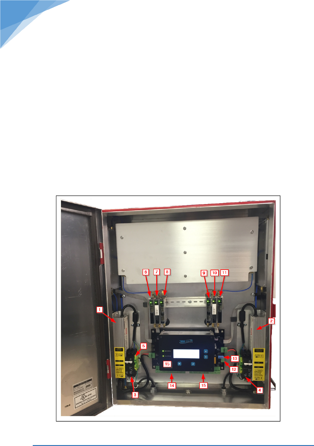
applications. The NFPA-compliant version of the signal booster includes a built-in dual power
supply system (Fig. 1.1 and 1.2) with a backup battery charging and monitoring system Fig.
1.15). It also includes two sets of alarm connections for status monitoring of the BDA
operation(Fig 1.14 and 1.15), antenna systems, battery capacity, power supply monitoring,
AC supply, temperatures, RF module status etc. (Fig. 1.14 and 1.15). All alarm conditions
are also logged as a simple text file on a removable SD Memory Card.
The two separate circuit breakers (Fig 1.3 and 1.4) are provided for easy power hookup and
for the increased reliability. The RF modules (Fig 1.6 – 1.11) are mounted on a DIN rail for
easy access and serviceability.
The unit is factory-set for specific frequencies and bandwidths and other than the gain and
power settings, it does not require any other field tuning or programming.
Figure 1

© 2016 Radio Solutions, Inc. Norwell, MA - USA
9
Installation Procedure:
1. Secure the signal booster to a solid, vertical surface such as an interior wall. The
signal booster enclosure has two mounting tabs on top and two on the bottom. For optimal
airflow, it is best to maintain at least 1” of spacing between the back of the enclosure and
the wall. This is best accomplished by mounting the enclosure on a grounded strut channel
(i.e. Unistrut, Kindorf etc.).
Please make sure that there is sufficient clearance around the signal booster enclosure to
ensure unobstructed airflow.
2. Connect the AC Power - The enclosure has 4 ½” trade size cutouts: two for power, one
for battery backup and one for alarm circuits. Diameter of the cutouts is 7/8” to allow for
easy installation of ½” trade size conduit fittings. The two power supplies have two separate
circuit breakers so that either a one shared circuit or two separate circuits can be connected
for backup and redundancy in mission-critical applications. Each one of the two dual circuit
breakers has the Line, Neutral and Ground connections. Please make sure that the green
ground terminal is connected to the ground wire and that is it secured to the DIN-rail. The
DIN rail is the ground path for the enclosure.
Warning – Live wire terminals on the circuit breakers!
Danger - Electrical Shock Hazard – Any high voltage and electrical ground connections must be done
by a qualified electrician. To prevent electrical shock when installing or modifying the system power wiring,
disconnect the wiring at the power source before working with uninsulated wires or terminals. Prior to powering up
the unit, please make sure that electrical ground is connected to both the DIN-Rail terminals inside the enclosure
and to the enclosure grounding bolt located on the underside of the enclosure. AC Power and RF Connections
should be installed with all standard installation practices for lightning protection. This includes grounding and
electrical bonding together of all equipment enclosures and grounding of the primary antenna cable and the
installation of proper surge suppression (lightning arrestor) equipment at the entrance to the building or the
equipment room.
3. Connect the Battery Backup – RSI Battery enclosure is designed to be installed
directly below the signal booster. Use the provided wire harness to connect batteries to the
battery power terminal on the PMU circuit board. Leave the battery fuse out for now. Please
only use the RSI supplied or RSI approved batteries.
4. Connect the Antenna system – Underside of the signal booster enclosure has two N-
Type connectors - the DAS system connector on the right side and the connector for donor
antenna on the left side, as labeled.
50 Ohm coaxial cable jumpers for both DAS (distributed antenna system) and for the donor
antenna must have solid outside conductor (such as ¼” - ½” Superflex, Heliax, etc.).
Coaxial cables with braided outside conductor may have excessive “signal leakage” that can
cause feedback and oscillation of the signal booster, especially when high gain settings are
used. Please ensure that both DAS and donor antenna systems are tested before they are
connected to the signal booster. Bad antenna connections, antenna line breakages etc. can
cause poor performance and RF intermod interference.
5. Power up the signal booster, insert the battery backup fuse
© 2016 Radio Solutions, Inc. Norwell, MA - USA
10
6. Set the signal booster gain for both uplink and downlink chains – the signal
booster ships from the factory with gain set to minimum. Gain can be increased as needed
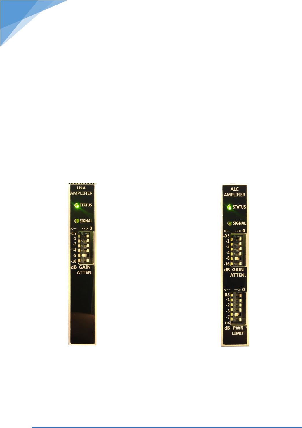
by setting DIP switches on LNA and ALC modules.
Figure 3 shows the LNA module with an example DIP Switch setting of -8dB. This introduces
8dB attenuation to the LNA module. For example, if the rated maximum BDA gain is 90dB
then: 90dB – 8dB = 82dB. So the BDA total gain now is 82dB.
Figure 4 shows the ALC module with 8dB gain attenuation.
With both modules settings as shown, BDA gain is calculated as follows: 90dB – 8dB (LNA
Attenuation) – 8dB (ALC Attenuation) = 74dB total gain.
System gain needs to be set for both downlink and uplink
7. Set the power limit – signal booster ships from the factory with output power set to
minimum. Power limit can be increased as needed by setting DIP switches on the ALC
module. Figure 4 shows ALC module with 7dB of power limit deduction. For example, if the
maximum BDA power is 32dBm then: 32dBm - 7dB = 25dBm maximum output power.
Figure 3
-
LNA Module
Figure
4
–
ALC Module

© 2016 Radio Solutions, Inc. Norwell, MA - USA
11
8. Connect the Alarms and the Booster Monitoring Annunciator panel (NFPA-
Compliant versions olnly)
The LED Light Indications:
Red “Signal” LED’s on both modules indicate that the ALC (Automatic Level Control) circuit
has been activated – i.e. input signal is high enough where amplifier needs to reduce the
gain to limit the output power to 32dBm max.
The Green “Status” LED’s indicates status of the module. Green LED light indicates that the
unit is powered up and no faults have been detected. No LED lights or a red status LED light
would indicate a problem with the module, such as: over/under voltage, over/under
temperature, over/under current draw or other module fault. All alarm conditions are
signaled to the central monitoring unit which then displays the alarm condition on the LCD,
logs the alarm condition with the current time stamp to the SD card and activates the BDA
fault alarm outputs.
© 2016 Radio Solutions, Inc. Norwell, MA - USA
12
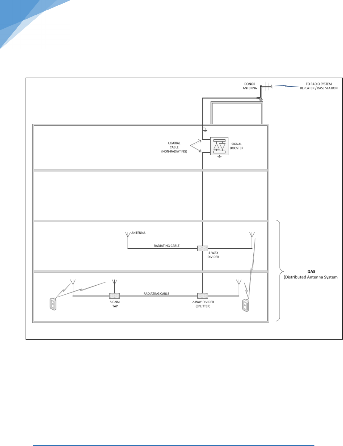
System Planning and Deployment:
Typical BDA System

© 2016 Radio Solutions, Inc. Norwell, MA - USA
13
1. Design the Distributed Antenna System (D.A.S) – Design the D.A.S for optimal
signal coverage of the building or other confined area. The D.A.S. system can be designed
by using a combination of radiating cable, non-radiating cable, antennas, signal taps,
splitters or hybrid couplers. To prevent feedback oscillations, a solid outer conductor, non-
radiating cable must be used to connect the booster to the D.A.S. and donor antenna
systems. If high gain antennas are used, it is important to limit the output power of the
signal booster so that the maximum ERP does not exceed the 5W limit (see the warning and
calculation instructions on page 2).
2. Locate the Donor Antenna – The Donor antenna should be a high-gain, directional
type antenna and should be aimed at the nearest radio system repeater site. Location of the
antenna should be chosen so that it provides highest possible signal isolation from the
D.A.S. system. It is important to limit the output power of the signal booster so that the
maximum ERP does not exceed the 5W limit (see the warning and calculation instructions
on page 2).
3. Measure the D.A.S. to Donor Antenna Signal Isolation – Probably the most
important step in design and deployment of an in-building signal booster system is to
ensure that there is a sufficient signal isolation between the donor antenna and the D.A.S.
system. Just like the feedback that occurs when the microphone and speaker get too close
together on a public address system, a signal booster can start to oscillate when the gain of
the system is higher than the isolation of the antenna system. The oscillations can cause
continuous in-band interference to other users that are in the range of the signal booster.
To prevent the feedback oscillation from happening it is important to ensure that the
amount of antenna isolation is at least 15dB higher than the signal booster gain. Antenna
isolation is measured by generating a test signal into the D.A.S. system and measuring the
level of the signal received off the donor antenna using a spectrum analyzer or other device
capable of accurately measuring RF signal levels. If a directional hybrid couplers are used in
the D.A.S. system then the same test should be performed in other direction by generating
the test signal into donor antenna and measuring the received signal level from the D.A.S.
system. Once the signal separation is measured, deduct 15dB from the figure and the result
is the maximum amount of gain that is allowed.
Example:
Test Signal Level generated into the D.A.S. system: 0dBm
Measured Test Signal Level at the Donor Antenna: -70dBm
Signal Isolation = 0dBm – 70dBm = 70dB
Maximum Booster Gain Allowed: 70dB -15 = 55dB

© 2016 Radio Solutions, Inc. Norwell, MA - USA
14
4. Follow the Good Engineering Practices and be a Good RF Neighbor - Good
engineering practice must be used in regard to the signal booster’s noise radiation.
Accordingly, the gain of the signal booster should be set so that the ERP of the output noise
from the signal booster should not exceed the level of -43 dBm in 10 kHz measurement
bandwidth. In the event that the noise level measured exceeds that value, the signal
booster gain should be decreased accordingly. Also, please note that in general, the ERP of
noise on a spectrum more than 1 MHz outside of the pass band should not exceed -70 dBm
in a 10 kHz measurement bandwidth.
5. Set the Booster Gain using the procedure described on page 10 to the value as
determined by following the step 3 and 4. System gain can be further reduced if required by
specific site conditions or factors.
6. Set the Booster Power Limit to the desired value using the procedure described on
page 10.
7. Power up the Booster and Test the Coverage. Class B broadband signal boosters are
permitted to be used only in confined or indoor areas such as buildings, tunnels,
underground areas, etc., or in remote areas, i.e., areas where there is little or no risk of
interference to other users.
© 2016 Radio Solutions, Inc. Norwell, MA - USA
15
This product is intended for installation by qualified personnel.
Please contact Radio Solutions, Inc. technical support for information about training, any
additional technical information and help with the product installation and deployment.
DESIGNED AND BUILT IN THE USA
*From domestic & imported components
Headquarters, R&D and Manufacturing Facility:
Radio Solutions, Inc. (RSI)
70 Accord Park Dr.
Norwell, MA 02061
Tel: 1-888-241-7197
+1-781-331-1008
Fax: +1-781-561-7770
info@radiosolutionsinc.com
www.radiosolutionsinc.com