Radio Systems 050237 M023700 Transmitter User Manual Manual
Radio Systems Corporation M023700 Transmitter Manual
Manual

B a s i c
In-ground Pet Fencing
S y s t e m
S D - 2 0 0 0
Operation Guide
Thank you for purchasing this Containment
System.
This electronic dog training system is among the
safest, most humane and effective training prod-
ucts you can buy. Used properly, the collar’s elec-
tronic stimulation serves as a distraction that your
dog will find undesirable. By complying, your dog
quickly learns to shut off the stimulation, thus
gaining confidence in response to your com-
mands.
Please take a few minutes to read the instruction
manual prior to first use and retain the manual for
future reference. This instruction manual contains
important programming and set-up information to
help your training proceed as successfully as pos-
sible. For best results follow these important safe-
guards:
I M P O R TANT SAFEGUARDS
1.Obey all warnings contained in this manual.
2. The electronic dog collar is intended only for
use on dogs over 6 months of age. Never attempt
to use this product for any purpose not specifical-
ly described in this manual.
3.If you have any reason to believe that your dog
may pose a danger to others, harm itself, or would
react adversely after receiving stimulations from
this containment system, you should not rely
solely on this product to contain your dog.
4. Do not leave the collar on your dog for more
than 12 hours per day.
5.Never perform set-up procedures when the col-
lar is on your dog.
6. Monitor the system prior to use and after
changing any settings to ensure that the unit is
operating properly.
7.Do not use this system if you suspect the bat-
tery in the collar receiver is low.
8. Keep out of the reach of children.
9. Your dog will not respond to your system
unless:
A.You train your dog and utilize the Training
tips section of this manual.
B.The collar receiver has a working battery.
Do not use if you suspect a low battery in it.
C.The collar receiver is worn properly by the
dog.
D.The collar receiver is adjusted so that the
probes are touching your dog’s skin.
E.The wall transmitter is on, connected to the
containment loop wire, and producing a
signal along the loop wire.
F. The 12-volt, 200 mAmp, adapter is
plugged into the wall transmitter and is
connected to a 110-volt household outlet.
10. The following precautions should always be
taken:
A.Never service or install a system or any
equipment during a thunder or electrical
storm.
B.Never install the wall transmitter where it
could be exposed to the elements. Doing so
will void the manufacturer’s warranty.
C. Monitor the wall transmitter periodically to
ensure that the unit is operating properly and
is producing a signal along the loop wire.
D. Always remove your dog’s collar receiver
before making any adjustments to your
system.
E.Allow your dog to get used to the collar
before you begin training. You want your dog
to accept the collar as part of a routine, not
to associate the collar with the stimulation.
11.To prevent the elimination of an adequate safe
zone in your yard, any adjustments to the field
width must be tested prior to using the system
with your dog. Once the field width has been set
and tested, turning the knob in a clockwise direc-
tion will increase the stimulation area and may
eliminate the safe zone, thus causing stimulations
to be present throughout your entire yard. If you
have questions, please contact Innotek®at 1-800-
826-5527, before using the system with your dog.
12. Realize that because individual dogs have
unique temperaments, there is no way of knowing
how your dog will react to its introduction to the
system. For the safety of your dog, initial training
should take place using a long leash to keep you
in control of the situation. Also realize that an
aggressive dog could turn against the handler
upon receiving the stimulation. Therefore, if you
feel your dog has an aggressive temperament
and/or it has a history of aggressive behavior, you
should consult a certified animal behav i o ri s t
before using this product.
1

13. Read all instructions before using this prod-
uct. If you have any questions or concerns after
reading this information, contact Innotek at 1-800-
826-5527.
I M P O R TANT NOT I C E :
This equipment has been tested and fo u n d
to comply with the limits for a Class B digi-
tal dev i c e , pursuant to Pa rt 15 of the FCC
R u l e s . These limits are designed to prov i d e
r e a s o n a ble protection against harm f u l
i n t e r ference in a residential installation.
This equipment genera t e s, uses, and can
radiate radio frequency energy and, if not
installed and used in accordance with the
i n s t ru c t i o n s , may cause harmful interfe r-
ence to radio commu n i c a t i o n s.H oweve r,
there is no guarantee that interference will
not occur in a particular installation. If this
equipment does cause harmful interfe r-
ence to radio or television reception, which
can be determined by turning the equip-
ment off and on, the user is encouraged to
t ry to correct the interference by one or
more of the fo l l owing measures:
• Reorient or relocate the receiving
a n t e n n a .
• Increase the separation between the
equipment and receive r.
• Connect the equipment to an outlet on a
circuit different from that to which the
r e c e i ver is connected
• Consult the dealer or an ex p e ri e n c e d
radio / TV technician for help.
C a u t i o n : Changes or modifications to any
component, not expressly approved by
Innotek, could void the user’s authority to
o p e r ate this equipment.
The term “ I C : ”b e fore the radio cert i f i c a t i o n
number only signifies that industry of
Canada technical specifications were met.
I N T R O D U C T I O N
Your new electronic containment system contains
three major components: a wall transmitter, a col-
lar receiver, and boundary wire.
The wall transmitter generates an electronic sig-
nal that is transmitted onto the boundary wire and
is received by the collar receiver when your dog
approaches the boundary wire.When the collar
receiver senses your dog is approaching the con-
tainment boundary, it will sound a warning tone
followed by a harmless, but effective electronic
stimulation. When trained properly, your dog will
quickly learn where its boundaries are.
This system has a range of up to 5 acres for con-
tainment.This package contains insulated bound-
ary wire for enclosing a yard approximately one-
half acre in size. Additional boundary kits can be
purchased from Innotek by calling 1-800-826-
5527. The system is also capable of containing
multiple dogs simultaneously. Although it is sold
with one collar receiver, additional collar receivers
can be purchased from Innotek.
Naturally, you are eager to get started training
your dog. But please take a few minutes to read
this manual first. It contains important set-up
information to help your training proceed as suc-
cessfully as possible.Proper preparation and
training will give your dog confidence for years.
C O M P O N E N T S
• One water-resistant collar receiver with nylon
strap and quick-release buckle
• One wall transmitter with installation hardware
• One 12-volt, 200 milliamp adapter to power the
containment system
• One 6-volt alkaline battery for the collar
receiver
• One test light for testing the collar receiver
• Fifty boundary flags
• One spool (500 feet) of 20 ga.insulated bound-
ary wire
• Short and long probes (one set each)
• Black plastic probes for first containment lesson
•Two waterproof splices
• One probe wrench
• Owner’s manual
• Instructional video
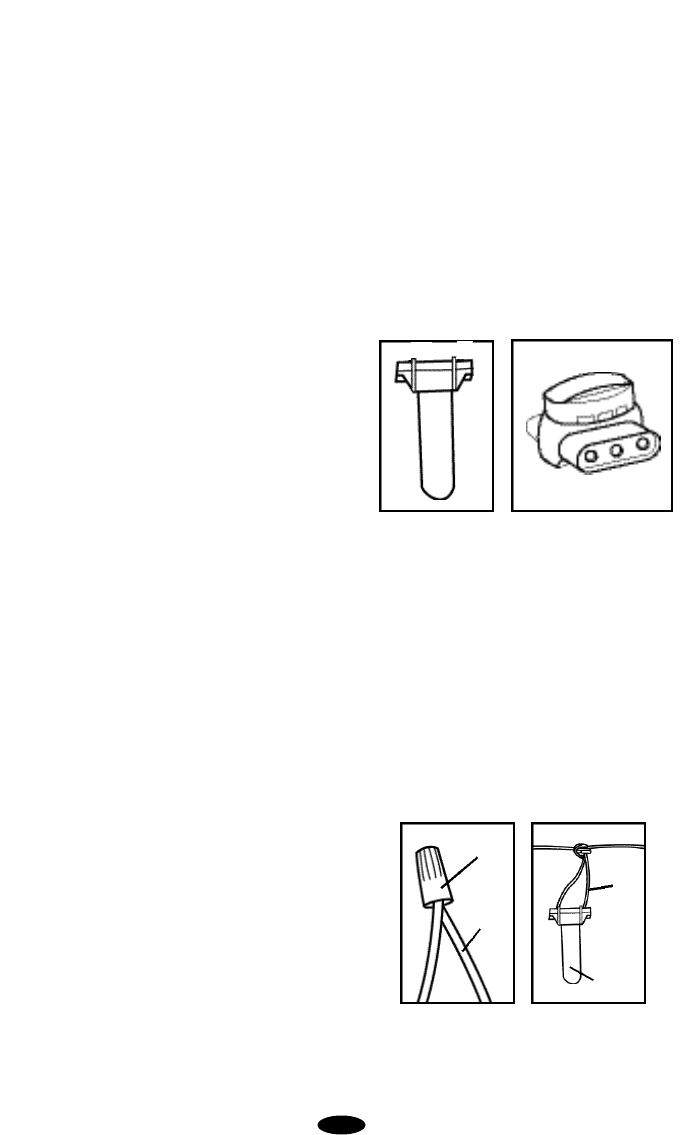
SETTING UP THE COLLAR RECEIVER
When you first set up the collar receiver, you will
need to insert the supplied 6-volt alkaline battery
in the battery compartment of the collar. Follow
these steps for installing or replacing the battery
in the collar receiver.
2
B. Wire Terminals: These easy-to-use, push-
release wire terminals let you instantly connect or
disconnect the boundary wire leads. W i r e s
should be stripped about a half inch before con-
necting to the wall transmitter.
C. Power: The wall transmitter is powered by a
12-volt, 200 milliAmp adapter that plugs into a
standard 110-volt household outlet and connects
to the power connector port on the side of the wall
transmitter.
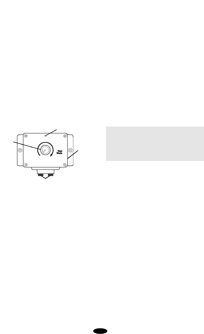
D. Field Width Adjustment Knob: This knob
controls the width of the signal field, the distance
from the boundary wire to the place where the
collar receiver first activates. Turning the knob
clockwise increases the field width; turning it
counterclockwise decreases it. Turning the knob
completely counterclockwise turns off the wall
transmitter power.
Important: Whenever a change is made using
the adjustment knob, the field width must be test-
ed and verified before using the system to contain
your dog. R e fer to Containment Opera t i o n ,
Section 2.F.Testing the System.
E.Indicator Light: The indicator light above the
Field Width Adjustment Knob tells the following
information.
1. Containment Mode = Solid Red Light: A
solid red light on the wall transmitter means the
transmitter is properly powered, both wires are
connected, and the wire forms an unbroken,
continuous loop. NOTE: The wall transmitter
light only indicates continuity.If you have a
loose splice or nicked wire, the red light or a
flickering light may still show, but you may notice
reduced or no field width. If this situation or a
wire break should occur, refer to Containment
Operation, Section 6.A.Troubleshooting.
2. System Malfunction = No Light: No light
tells you one or more of the following: One or
both wires are not properly connected; both
wires are connected but the wire is broken or
nicked at some location in your installation; the
wall transmitter is off; the power has been dis-
connected; or the wall transmitter has malfunc-
t i o n e d . R e fer to Containment Opera t i o n ,
Section 6.Troubleshooting.
1.Place the collar receiver on a flat surface
with the battery cap facing up.
2.Using a coin or a screwdriver, turn the bat-
tery cap counterclockwise to loosen and
remove it.
3.Insert the 6-volt alkaline battery into the bat-
tery compartment with the positive (+) end
closest to the battery cap.
4.Replace the battery cap by turning it clock-
wise until it is firmly seated.
C O N TAINMENT OPERAT I O N
SECTION 1.
F E ATURES OF THE WALL
T R A N S M I T T E R
The wall transmitter is your system’s control cen-
ter and works with the collar receiver and bound-
ary wire to keep your dog safely contained within
an area you select. The wall transmitter contains
the following features:
A.Lightning / Surge Protection: This helps pre-
vent damage to the wall transmitter if a power
surge occurs or if lightning hits in the vicinity of
your home. However, a close lightning strike may
damage the unit. Therefore, Innotek recom-
mends that you unplug the transmitter and dis-
connect the wires during storms. A lifetime-war-
ranted lightning protection module can be pur-
chased to protect the wall transmitter from both
AC power surges and containment wire surges
that occur during a close lightning strike. Contact
Innotek for more information.
Indicator light
Power port
Field width
Wire terminals
3
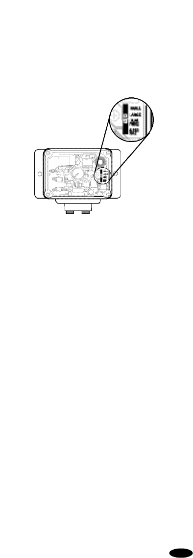
F. Yard Size Jumper: The yard size “jumper”
allows you to customize the wall transmitter for
your installation. The wall transmitter comes from
the factory with the jumper set for a small yard
that utilizes less than 1,000 feet of boundary wire.
It can be changed to accommodate a large yard
that has more than 1,000 feet of boundary wire in
the installation. One 500-foot spool of boundary
wire is included with your system.
To access the Yard Size Jumper, turn the Field
Width Adjustment Knob to the “Off” position.
Remove the four cover screws, the Field Width
Adjustment Knob, and the front cover from the
wall transmitter. The Yard Size Jumper is located
on the right side of the circuit board. When the
jumper covers the two pins next to SMALL, the
wall transmitter is set for a small yard; when the
jumper covers the two pins next to LARGE, the
wall transmitter is set for a large yard. THE
JUMPER MUST BE IN PLACE FOR THE CON-
TAINMENT SYSTEM TO FUNCTION.
When the yard size jumper is appropri a t e l y
placed for your installation, replace the wall trans-
mitter cover, secure it with the four cover screws,
and install the Field Width Adjustment Knob with
the pointer in the “Off” position.
G. Dual Frequency Jumper: The dual frequen-
cy jumper located inside the wall transmitter is
labeled DUAL FREQ and 8.192 KHz. It should
always be set for 8.192 KHz. Do not move this
jumper unless instructed to do so by an Innotek
representative.
H. Stimulation: The stimulation delivered in the
containment system is preset. There are three
special features that increase the effectiveness
for containing your dog.
1. Pre-Stimulation Warning Tone: When the
dog reaches the edge of the signal field in the
yard, it will hear a pre-stimulation warning tone
that lasts about two seconds.If the dog does not
return to the “safe”part of the yard, it will receive
a continuous stimulation until it does re-enter the
“safe”part of the yard.
2. Run-Through Prevention: The receiver
automatically increases the stimulation when the
dog continues more than 1/3 of the way through
the signal field. For example, if the signal is
detected 12 feet from the wire and your dog
enters the signal field, this feature is activated
when the dog is eight feet from the wire. At this
point, the dog automatically receives the High
level of stimulation. The feature acts as an over-
ride to the pre-stimulation warning tone so the
dog cannot “run through” the system without
activating a strong stimulation. As the dog
retreats into the yard, the stimulation will reduce
to the preset stimulation level and then turn off
as the dog returns to the safe part of the yard.
3.Over-Stimulation Prevention: In the unlike-
ly event that your dog becomes “trapped” in the
signal field, this feature limits stimulation dura-
tion to 10 seconds. The system shuts off for 10
seconds before resuming stimulation for another
10 seconds. This pattern will repeat for a maxi-
mum of three cycles, a duration of 60-seconds.
Removing the receiver from the containment
field will reset the unit and allow normal opera-
tion.
SECTION 2.
I N S TALLING THE CONTA I N M E N T
S Y S T E M
A. Creating the Layout
When selecting a layout for your containment sys-
tem, keep it simple; complex installations are
more difficult for dogs to learn. Here are some
key points to remember:
• Consider all the obstacles - gardens, play areas,
driveways, sidewalks, pools, porches, and water
crossings.
• Utility companies must be contacted to mark the
buried utility lines.
4
•To avoid future wire breaks caused by landscap-
ing efforts, the lawn should never be aerated in
the vicinity of the containment wire.
• For your dog's safety, it is recommended to keep
the containment wire at least ten feet from the
street.
• Keep in mind that you will want at least an 8- to
12-foot containment field (8 to 12 feet on each
side of the wire).
• It is possible to cancel the containment signal in
a portion of the containment loop by twisting the
wires 2 to 3 inches apart. This allows the dog to
cross the twisted containment wire in safe areas
of the yard, as illustrated below, without causing
your dog’s collar receiver to deliver stimulation.
Described below are several popular containment
installations. You may find these helpful in plan-
ning the layout that will best meet your needs.
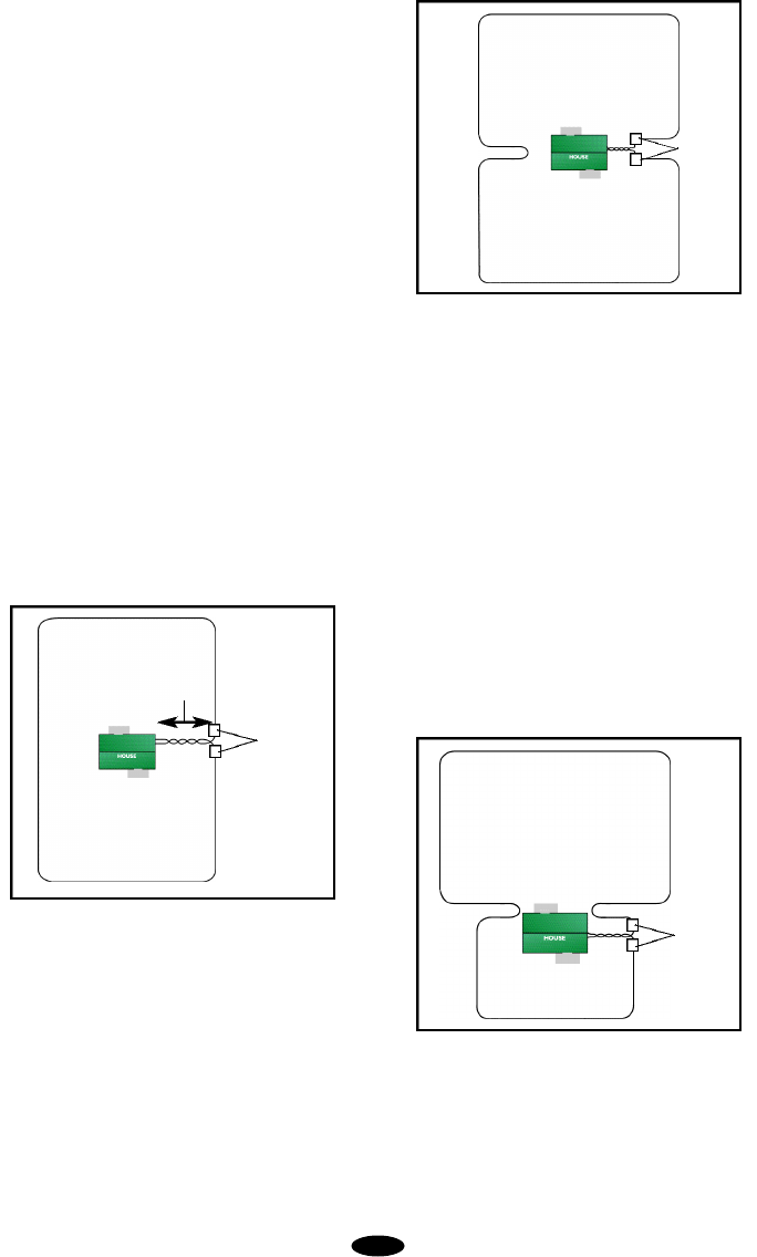
The perimeter loop is the most common installa-
tion. The wire is placed just inside the property
line and usually forms a square or rectangle.
The hourglass design allows your dog to be con-
tained in either the front or back yard. This layout
is similar to the perimeter loop, except the wire is
run close to the house on two sides. When posi-
tioning the wire parallel to itself as it goes toward
the side of the house from the perimeter, keep it
a distance equal to the field width plus three feet
from itself. To prevent your dog from playing in the
side yard, keep the wire a distance equal to the
field width less one foot from the house.
The back yard loop encloses the back yard and
uses the back portion of the house as part of the
barrier. After laying wire on the three sides of the
back yard, bring the wire a distance of the field
width less one foot from the back corner of the
house to prevent your dog from playing in the side
yard. When running the containment wire parallel
to the side and around the front of the house,
keep the wire a distance from the house equal to
the field width plus three feet to prevent sending
s t i mulation through the walls of the house.
Continue placing wire at this distance from the
home until it reaches the entry hole leading to the
wall transmitter.Encircling the house contains
your pet if he bolts out of the front entrance or the
g a rage door. These areas are usually not
flagged.
A double loop installation will provide a barrier in
the back yard without running wire into the front
yard. Beginning at the wall transmitter, lay the
containment wire to the nearest perimeter and
proceed around the back yard until you are at the
Perimeter Loop
Hourglass Design
Backyard Loop
5
splice
containment signal
cancelled in this area
splice
splice
opposite side of the house.When at a distance
from the corner of the house equal to the con-
tainment field width less one foot, do a hairpin
turn and continue positioning the wire a distance
of the field width plus three feet away from itself.
Proceed around the back yard until you return to
the opening leading to the wall transmitter. This
design will keep the back entrances to the house
free from stimulation.
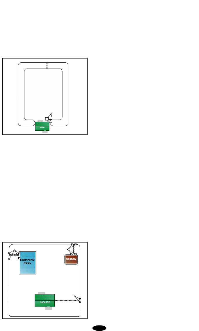
Your containment installation can be customized
to protect areas such as gardens, pools, and spe-
cific landscaping. To accomplish this, encircle the
protected area with containment wire. Twist a
length of boundary wire equal to the distance
between the protected area and the containment
perimeter. Use waterproof splices to connect the
twisted wire to the containment wire at the
perimeter and at the protected area. The con-
tainment signal is cancelled where the twisted
wire is located thus allowing your dog to run
around the garden or pool without receiving stim-
ulation. The containment signal around the pro-
tected area will keep your dog out just as the
perimeter containment wire keeps him in.
Once you are satisfied with the layout of your con-
tainment system, it is time to choose a proper
location for the wall transmitter.
B.Installing the Wall Transmitter
1 . Selecting a Location for the Wa l l
Transmitter - Select a location for the wall trans-
mitter that is within five feet of a standard,
grounded 110-volt household outlet and that will
provide easy access to an exterior wall where
the containment wire can penetrate. If possible,
avoid plugging the unit into an outlet that is pro-
tected by a ground fault current interru p t e r
(GFCI). The GFCI will not interfere with the nor-
mal operation of your system, but in rare cases
lightning strikes may cause a GFCI outlet to trip
(disconnect power), and you would need to reset
the GFCI to restore household power to the sys-
tem. Also check the location where you want to
bring the outside wires through the wall and into
the wall transmitter to avoid electrical or tele-
phone wires, television cables, or water pipes.
Even after checking, there may be unknown
wires or pipes inside the wall. Therefore, con-
sider going through a windowsill or doorframe
whenever possible.Mark the desired location
with a pencil.
The transmitter may be mounted on a hollow
wall or directly to a wall stud using the provided
mounting hardware.The wall transmitter will
withstand freezing temperatures, but it is not
waterproof. Therefore, it is best to locate the
transmitter in a dry, enclosed area where the
temperature range will be between 32OF and
110OF (0OC to 45OC). Preferable locations are
the garage, laundry room, office, or finished
basements. For ease in accessing the wall
transmitter, mount the transmitter at least four
feet from the floor.
2.Installing the Wall Transmitter - After select-
ing a location for the wall transmitter, use a pen-
cil to transfer the screw hole locations on the
side of the wall transmitter onto the wall. Make
sure there are no electrical wires or other
objects directly behind the mounting-hole loca-
tions that may be damaged when the mounting
screws are installed.
For hollow wall installations, drill 1/4-inch diame-
ter holes at the marked locations and tap in the
6
splices splices
splices
Double Loop
splice
6 ft.

hollow wall fasteners with a hammer. For instal-
lation of mounting screws directly into a wall
stud, drill 3/32-inch diameter pilot holes at the
marked locations. Position the wall transmitter
with the screw holes over the pilot holes and
secure with the supplied screws.
At the pre-determined location where the contain-
ment wires will enter the home, drill a 1/4-inch hole
from the inside through the wall or corner of a
windowsill or door frame.A slight downward
angle will help the wire to curve downward out-
side and keep water out.
A masonry bit can be used to drill through cin-
derblock or through the joint crack on brick or
stone walls. A regular 1/4-inch drill bit can be
used if the house is of wooden construction with
vinyl or aluminum siding. In these cases, you
may want to drill from the outside for exterior
aesthetics.
C. Planning the Placement of the Boundary
Wire
With the wall transmitter installed and the hole
drilled for the wires, begin positioning the bound-
ary wire according to your layout. Listed below
are some helpful instructions and tips.
1. Amount of Wire - Your system includes 500
feet of insulated 20-gauge, solid copper core
wire. For yards requiring more wire, boundary
kits are available from Innotek (1-800-826-
5527). It is important that the same gauge wire
be used throughout the installation. Here are
some examples of wire coverage.
Acres Linear Feet Needed
1 850
2 1200
3 1500
4 1700
5 1900
The above figures assume a rectangular layout
and actual footage may vary.
2. Placement of the Wire - For the system to
work properly, the wire must make one continu-
ous loop. The signal is transmitted from one ter-
minal of the transmitter, through the wire, and
back to the other terminal. When placing the
wire, keep in mind that you will want at least an
8- to 12-foot containment field (8 to 12 feet on
each side of the wire). Avoid making passage-
ways too narrow or your dog may be hesitant to
use them (i.e. along the sides of a house).
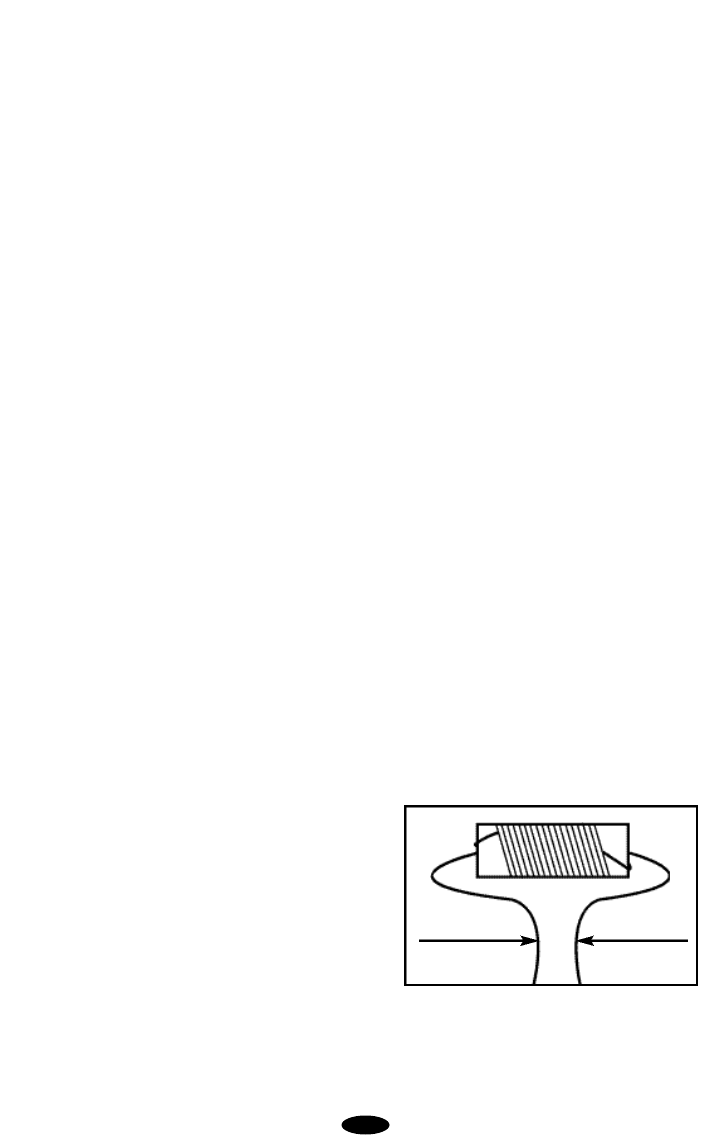
3.Twisted Wire - Prepare and place twisted wire
from the transmitter to the exterior loop wire.
The twisted wire cancels the signal and allows
your dog to cross this area. It can also be used
to connect the containment system to internal
areas that should be protected, like gardens,
pools, and special landscaping.
To twist the wire, cut two equal lengths and hold
them side by side. Put one end of both wires in
a power drill. With a helper holding the other
ends of the wires, turn the drill on and spin the
wires until the twists are 2 to 3 inches apart. The
tighter the twisting of the wire, the better the sig-
nal cancellation. The wire can also be twisted
manually.
4.Rounding Corners- Use gradual turns at the
corners with a minimum of 2.5-foot radius. This
will produce a more consistent containment field
and avoid confusing your dog in these areas.
5.Crossing Driveways, Sidewalks,and Water
Features -When crossing an asphalt driveway,
make a 1/2-inch deep cut across the driveway
using a circular saw and masonry blade. Place
the wire in the crack and seal with asphalt
sealant. On driveways and sidewalks, if an
expansion joint is available, simply place the
wire in the joint and seal with an outdoor caulk.
When crossing gravel, bury the wire at least 3
inches deep.Use a piece of garden hose or
plastic PVC piping to protect the wire. In water,
anchor the wire with large rocks.Protect the
wire with a piece of garden hose or plastic PVC
piping. The wire does not have to be buried, but
to minimize the potential for wire damage, it is
advisable to bury it at least one inch under-
ground.
D.Placing the BoundaryWire
1. Listed below are important tips about place-
ment and burial of the boundary wire:
7
• Do NOT bury the loop within 10 feet parallel to
electrical, telephone, cable TV, or other buried
wire in the yard.
• Do NOT bury one section of wire within 10 feet
of another section or the signal may cancel.
• Do NOT bury your wire within 10 feet of a
n e i g h b o r ing containment system’s boundary
wire.
2. Position the Wire in the Yard -The above
recommendations may cause you to modify
your layout, but it will be time well spent. When
your layout is finalized, place the wire around
your property according to your diagram. The
wire loop should begin and end at a perimeter
location closest to the location of the transmitter.
This will minimize the amount of twisted wire
needed to connect the boundary wire to the
transmitter.
DO NOT BURYTHE WIRE UNTIL YOU HAVE
TESTED THE SYSTEM AND ARE SURE IT IS
WORKING PROPERLY. TAKE CARE NOT TO
NICK OR SCRAPE THE WIRE INSULATION
DURING THE INSTALLATION. AN INTERMIT-
TENT SIGNAL OR NO SIGNAL MAY OCCUR.
E.Making the Final Connections
After the wall transmitter has been installed in a
protected area and the boundary wire is in place,
the final connections must be made.
1. Bringing the Outside Wire to the Wall
Transmitter - From the outside, push the twist-
ed pair of wires through the hole in the exterior
wall. A small piece of electrical tape wrapped
around the end of the wire will keep it from
untwisting in the wall. Push a sufficient length of
wire through the wall to reach the wall transmit-
ter. Strip about 1/2 inch of insulation from each
wire and insert them into the wire terminals on
the wall transmitter by depressing the tabs on
the terminals and inserting one wire in each ter-
minal. Position the wire along the wall as
desired and push excess wire back out through
the hole in the wall.
2. Splicing to the Boundary Wire - Pull the
twisted pair wire to the perimeter location of the
boundary wire. Make sure that the wire length is
adequate to route wire along the outside wall
and bury before cutting. Splice the ends of the
twisted wire to the ends of the boundary with the
supplied waterproof splices.
WARNING: Use only the waterproof splices
(approved for direct burial) supplied with this
system. If additional splices are required, they
may be purchased from Innotek. Using non-
waterproof electrical tape, solder, or twisted wire
nuts will cause an intermittent signal or disable
the system. The waterproof splices included in
your containment system are designed to pro-
vide a sealed connection between the wires.
Waterproof Splices–Your containment system
includes one of two different styles of waterproof
splices that are designed to provide a sealed
connection between the wires.Refer to the fol-
lowing illustrations to identify the splices includ-
ed with your system.
Gel-Filled Capsule Splice–To use the gel-filled
capsule splice, strip 5/8 inch of insulation from
the ends of the wires you are joining. With the
ends of the wires even and together, place the
wire nut over the wire ends and turn the wire nut
clockwise until it is securely fastened. Snap
open the hinged lid of the gel-filled capsule and
insert the wire nut as deeply as possible into the
waterproof gel. Snap the lid shut, making sure
the wires exit the splice on either side.Tie a
knot in the wires as shown in the diagram to
prevent them from pulling out of the gel-filled
capsule when the wire is buried.
Black Cap Splice–To use the black cap splice,
a single boundary wire is placed into one of the
three holes of the spliced.The insulation on the
boundary wire should not be stripped before
8
Gel-filled capsule splice Black cap splice
Gel filled
capsule
Wire
Wire nut
Wire
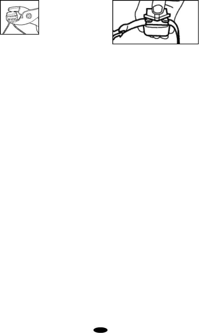
placing wire into the holes.
The other single boundary
wire is placed into one of
the other holes. T h a t
leaves one extra hole that
is not used.A pair of pliers
should be used to press down on the top black
part of the splice.
3.Plugging in the Power Adapter - Make sure
the Field Width Adjustment Knob is in the OFF
position. Plug the power adapter into a nearby
110-volt household outlet and the other end into
the power port on the right side of the wall trans-
mitter.
4. Checking Out the Installation - Make sure
your dog is not wearing the collar and no one is
touching the collar probes. Turn the Field Width
Adjustment Knob clockwise until a click is heard.
This turns the system on. The LED on the wall
transmitter should be solid red to indicate the
boundary loop is properly connected. If the red
light does not illuminate, refer to Containment
Operation, Section 6.Troubleshooting.
F.Testing the System
With the boundary wire in place and properly con-
nected and the collar receiver battery installed, it
is time to set the containment field and test the
system. THE COLLAR RECEIVER SHOULD
NOT BE ON YOUR DOG WHEN THE SYSTEM
IS TESTED.
1. Setting the Yard Size- If you are using a
total boundary wire length of 1,000 feet or less,
set the Yard Size Jumper to SMALL. Otherwise,
set it to large.Refer to Section 1.F for setting the
jumper.
2. Adjusting the Containment Field - The
width of the containment field is adjusted using
the transmitter’s Field Width Adjustment Knob.
Start with a low setting. Move the knob to the 9
o’clock position and test the field width of the
system. For the safety of your dog,the field
width of the system must be tested whenev-
er an adjustment is made to the containment
field. Please follow the instructions below.
3. Testing the Field Width of the System -
Select a section of straight boundary wire that is
at least 50 feet long and perform the contain-
ment field test at the center of the selected sec-
tion. To test the containment field, attach the
test light to the probes and slowly walk the col-
lar receiver toward the boundary wire. The col-
lar receiver should be held at the height of your
dog’s neck with the probes pointed upward.
Listen for the warning sound and watch for the
test light to illuminate.The wider the contain-
ment field, the less chance the dog can run
through the field.
The containment field should extend at least 8
to 12 feet on each side of the wire. This helps
make the Run-Through Prevention more effec-
tive. To increase the field width, turn the Field
Width Adjustment Knob clockwise and recheck
the distance the signal is broadcasting from the
w i r e. To decrease, turn counterclock w i s e.
Repeat this procedure until you are satisfied
with the location of the stimulation throughout
the installation.
Note: When testing the field width, the collar
receiver may demonstrate the over-stimulation
p r evention safety feature described in
Containment Operation, Section 1.H.3. Over-
Stimulation Prevention.
4. Verifying the Safe Part of the Yard - Once
the field width is set, slowly walk the collar
receiver around the entire boundary perimeter
maintaining a distance from the wire that is at
least three feet farther than the field width set-
ting selected in the previous step. Verify the col-
lar receiver does not activate. Inconsistencies
in the field width may occur where there are
buried electrical, telephone, cable TV or other
wires or metallic objects in the yard. The con-
tainment signal from the boundary wire can
couple onto the buried wires and extend the sig-
nal into the safe part of the yard. Repositioning
the boundary wire in these areas can minimize
the unwanted signal coupling; however, you
may not be able to completely eliminate the
effect. The unwanted signal coupling can be
9
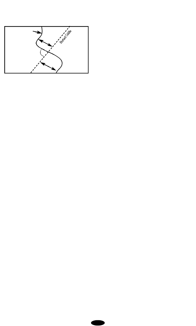
minimized by orienting the boundary wire so
that it is perpendicular to the buried wire for
approximately ten feet on each side of the
buried wire (see graphic below).
5.Burying the BoundaryWire -You may need
the fo l l owing tools for efficient installation:
S t raight-edged spade, pliers, and wire
cutter/stripper. If you plan to run the wire across
concrete, you will also need a caulk gun, sili-
cone caulking, and a circular saw with a mason-
ry blade.
a. Ensure the system is turned OFF at the
wall transmitter.
b. Burying the wire - To bury the wire, dig
about 3 to 4 inches deep where the wire first
enters the ground near the transmitter and
continue around the path of the loop wire. A
30Oto 45Oangle cut made with a flat blade
spade will be the easiest to close and heal.
Allow for slack in the wire throughout the
boundary wire loop to compensate for expan-
sion and contraction due to tempera t u r e
changes.
When covering a large area, you may wish to
use a lawn edger or trenching machine to cut
into the ground. However, we recommend
that the wire be placed in the trench by hand.
A commercial wire-placement machine may
break the wire or damage the wire insulation.
c. Checking the system field width and plac-
ing the flags - Repeat Testing the System
(Containment Operation, Section 2.F.3.) until
you are satisfied with the field width setting.
As you approach the boundary wire, place a
flag at the perimeter where the receiver first
detects the warning tone. This will add a visu-
al cue to the audio warning tone and help the
dog learn the boundary. Continue placing the
flags at 6- to 8-foot intervals around the entire
containment area using this technique.
If the field adjustment knob position is altered,
you must test the containment field for the
desired setting and reposition the flags as
necessary.
d.Plugging the holes - With the twisted wire in
place near the wall transmitter, caulk and seal
the interior and exterior holes to prevent dam-
age from moisture and insects.
SECTION 3.
USING THE CONTAINMENT SYSTEM
A.Fitting the Collar to Your Dog
1. Probes - Use short probes for shorthaired
dogs. Use long probes for longhaired dogs.
Finger tighten the probes, then turn one addi-
tional revolution with the probe wrench. Do not
over-tighten the probes.
2. Collar Strap - Place the collar around the
dog’s neck with the receiver box under the chin.
Fit the strap as snugly as possible, without
restricting breathing. There should be enough
room to fit only one finger between the strap
and the dog’s skin at the back of its neck. Make
sure both probes contact the dog’s skin.
Remove the collar and trim any excess strap
length, leaving 4 to 6 inches. Then seal the end
with a lighted match for 1-2 seconds. This will
prevent fraying.
B. Important Notes About the Collar
1. Always use the rubber insulators between
the collar strap and probes to provide insulation
in damp conditions.
2. If needed, a small amount of hair removal or
thinning will improve probe contact with the
skin. Do NOT shave the dog’s neck.
3. Check your dog's neck weekly for skin irrita-
tion.
4. This product is not recommended for dogs
under six months of age.
5. Check the tightness of the probes regularly
and frequently to prevent loss of the receiver
box.Lost receivers are not covered under man-
ufacturer warranty.
10
Boundary Wire
10’
10’
90˚

6. To prevent accidental stimulation inside the
home, remove the collar from your dog's neck
when it comes inside.
7. Check the collar receiver once a week to
make sure the collar receiver battery has ade-
quate power.
8. Test the collar receiver in the containment
field weekly to verify that the system is func-
tioning properly. To test, hold the supplied test
light to the collar receiver probes. Holding the
receiver by the case, NOT by the probes, walk
into the containment field. With the receiver
held at the height of your dog with the probes
facing upward, verify the warning tone is pres-
ent and the test light illuminates.
SECTION 4.
TIPS FOR CONTAINMENT TRAINING
To get the most out of your containment system,
keep these tips in mind:
A. The collar receiver must be properly fit to
ensure adequate contact between your dog’s
skin and the receiver probes.Place the collar
high and snug on your dog’s neck.
B. Never leave the collar receiver on your dog
for longer than 12 hours a day. Leaving the col-
lar on your dog for extended periods could
result in irritation around the neck or at the site
where the probes make contact with the skin.
C. Begin training when your dog has reached
four to six months of age.
D. Always make sure the collar is functioning
properly BEFORE putting it on your dog. Verify
the containment transmitter is operating proper-
ly and the field width is appropriate. To test the
containment field, refer to Containment
Operation, Section 2.F.3. Testing the Field Width
of the System.
E. Remove any metal collars or tags from the
dog when it wears the electronic collar. Metal
collars and tags can cause intermittent opera-
tion and/or prevent the dog from feeling the
stimulation.
F. Place the training flags at the perimeter
where the warning tone is heard. This will add
a visual cue to the audio warning tone and help
your dog learn the boundary.
G. Never call or pull a dog into the containment
field.
H. Keep training sessions brief (10 to 15 min-
utes) and stop the session before your dog has
lost interest. Take a break to rest or play.
I. Do NOT become overly confident that your
dog has become conditioned sooner than
expected. Complete all of the steps in the
Training Plan before allowing your dog to run
free.
J. ALWAYS praise your dog for good behavior.
SECTION 5.
THE TRAINING PLAN
Review the video that is packaged with the sys-
tem.It offers a visual step-by-step guide to train-
ing your dog.
The goal of containment training is:
•To teach your dog to identify and retreat from the
boundaries.
•To make the training fair--so your dog will under-
stand the consequences of leaving the yard.
• To make the training fun--so your dog will enjoy
staying and playing on your property.
This training plan is divided into four part s :
Training Equipment, The Schedule, Rules and
Routine, and Training Lessons.
A.Training Equipment
You'll need a training collar.Choose either a flat or
slip collar. Use a flat collar on a mild mannered
dog.A slip collar works best on a hard to handle
or easily distracted dogs.
You'll need a lead.This training plan recommends
that you work with a 6-foot, 15-foot, or retractable
lead.
11

B.The Schedule
The six dog-training lessons take place over the
course of about 4 weeks. For total success it is
necessary to complete the entire course.
Practice sessions are 10-15 minutes each, 2
times per day.Short, fun sessions are more effec-
tive. Anything longer will cause your dog to men-
tally tire.
Lesson 1: The Retreat Pattern - 6 Sessions.
Lesson 2: The Stimulation - 1 Session.
Lesson 3: Distractions - 7-8 Sessions.
Lesson 4: Off Lead, Supervised - 1 Week
Lesson 5: Off Lead, Unsupervised - 2 Weeks
Lesson 6: Flag Removal - Every other day until
gone.
Use the calendar only as a guideline. Your dog's
behavior tells you when to move to the next les-
son.
C.Rules and Routine
The rules and routine of the typical training ses-
sion include putting the collar receiver and lead
on your dog making sure the collar receiver is
high on your dog's neck and snug with the probes
touching the skin.
Start every session with play and praise. Make
sure the dog is comfortable--have fun! Laugh! and
praise him.
Most importantly, review the previous day's les-
son to see if your dog is learning on schedule. Do
not proceed to the next step until your dog under-
stands what is expected. Do boundary work at
locations all around the property. End the session
with relaxing play.
Bring your dog indoors and remove both the train-
ing collar and the collar receiver.If you're training
more than one dog, train each dog at separate
training sessions.
D.Training Lessons
Lesson 1: The Retreat Pattern
Before you start to train, make sure the collar
receiver is functioning and the battery has ade-
quate power. Remove the standard probes and
install the black plastic probes.The black plastic
probes ensure that your dog does not receive a
stimulation until he learns to retreat from the
boundary.
Put the collar receiver on your dog.Make sure the
wall transmitter is turned on.
Lesson 1- Day 1. The goal for Day 1 is to intro-
duce your dog to the boundary and to help him
understand he should retreat when he hears the
warning sound. Depending on the lead there are
several ways to do this.
Using a 6-foot lead, casually walk your dog to the
boundary.When the dog reaches the containment
field let go of the slack in your left hand, immedi-
ately spin to your right, and instantly grasp the
lead under your right hand and retreat.Your dog
will continue forward and then feel the tug. As he
runs back towards you, praise him.
Using a retractable or 15-foot lead, casually walk
your dog toward the boundary.Your dog may indi-
cate he hears the warning sound by tilting his
head or twitching his ears.The instant the dog
hears the warning sound, give a tug on the lead
and bring him back.
On a retractable lead, press the brake. This will
redirect the dog back into the safe area.Have fun
and praise him.
On days two and three repeat the lesson of Day
1.
As the training sessions progress through the
three days of lesson one, you'll see that your dog
will begin to anticipate the signal and retreat with-
out prompts.
Day three is successful if your dog retreats with
no prompt from you or he refuses to approach the
boundaries. Remember to praise, praise, praise
proper behavior.
Lesson 2: The Stimulation
A dog may be tempted to break the rules.To pre-
vent this, he must understand that there are con-
sequences for inappropriate behavior.When your
dog retreats from the boundaries on his own or
12
MTWT F S S
Week 1 Retreat Distractions
Week 2 Off Lead Supervised
Off Lead Unsupervised
Flag Removal Every Other Day
Week 3

won’t go into flagged areas, he is ready to receive
the stimulation.
Before you begin this lesson, remove the black
plastic probes and install the standard probes.
Make sure the wall transmitter is turned ON and
functioning properly.
Use a 15-foot or a retractable lead.Have a family
member run through the containment field. Let
your dog follow.The distracter must not stop, look
back, or call the dog.After your dog receives the
stimulation, pull him back to you and lavish him
with loud, happy pra i s e . Try it again. If he
responds correctly, praise him, then move to
another boundary area.
Lesson 3: Distractions
If your dog is avoiding the boundary, he is ready
for distractions.This is the most important but
often shortchanged part of the training. This les-
son teaches your dog that he must resist tempta-
tions. When practicing distractions, never call or
pull your dog into the containment field.
Most dogs have a hard time generalizing con-
cepts so you can't assume that if your dog won't
chase a ball he won't chase a bicycle.You have to
go through a list of distractions that will tempt your
dog the most.Dogs will learn specifics.If your dog
likes to chase, distract with balls, bikes--anything
that moves. If your dog is attracted by children,
family members, other dogs--use them as temp-
tations.
Lesson 4: Off Lead, Supervised
After several sessions of distractions, your dog
should be ready for off lead play.You must stay in
the yard for off lead training.
In fact, it's wise to spend more quality time in the
yard with your dog.The more your dog stays on
the property for the first month, the less confused
he will be.
If you wish to take your dog off the property,
remove the collar receiver and take him off and
back onto the property in the car.
Lesson 5: Off Lead, Unsupervised
When your dog resists distraction of any kind,
both on and off lead, he can be left unattended in
the yard but observed from inside the home.This
freedom should be brief at first. You must fre-
quently go out and check on your dog. Over the
next several weeks, unsupervised freedom can
be gradually increased.
Before and after each unsupervised session, you
must continue the play and praise routine so that
your dog understands that the yard is a happy
place to be.
Lesson 6: Removing the Flags
After 2 weeks of successful unsupervised con-
tainment, you can begin removing the flags.Start
by removing every other flag every other day until
all are gone.
The leads, trainers, flags and the collar receiver
signals are all training clues for your dog. During
the last three weeks of training --one by one--all
but the collar receiver will be removed.
As the training clues are removed it is essential
that you continue to use distractions to make sure
your dog retreats from the unmarked boundary.
The stimulation teaches the consequences of the
improper response.Know your dog and what
tempts him.Gradually extend the amount of unsu-
pervised freedom, and finally remove the flags
when you are confident that your dog is fully
trained.
If you have any questions about your containment
system, or about training your dog, please review
the video included with this product. If you still
have questions or concerns, please call Innotek.
SECTION 6.
T R O U B L E S H O O T I N G
Always remove the collar from the dog before doing any troubleshoot testing.
The following table identifies the solutions to common problems associated with pet containment systems.If
a problem occurs, first check this table and try to determine what the problem may be.If, for any reason, your
system still does not operate as described in this manual or if you have any questions or problems not includ-
ed in this manual, please call Innotek at 1-800-826-5527.
13

Dog Response Problem Possible Solutions Reference
1.Dog appears to not “feel”the A.Collar fit is not tight enough to make good
stimulation skin contact. Page 10
B. Make sure black probes are not on collar
receiver. Use standard probes.
C. Probes are not long enough to
make skin contact. Page 10
D. Dog’s hair is too long or thick. Trim the
hair or order special thick-haired probes
from Innotek. Page 10
E.Receiver battery needs to be replaced. Page 3
F.Verify the wall transmitter is on and
functioning properly. Page 3
G.Remove any metal collars and tags
from the dog. Page 11
2.Dog appears to“feel”the A.Collar fit is not tight enough to make good
stimulation, but still skin contact. Page 10
constantly enters the containment B. Field width setting is not wide enough. Page 9
field. C. Remove any metal collars or tags
from the dog. Page 11
D. Additional training may be needed. Page 11
3.Dog receives an intermittent A.Use of non-waterproof connections. Page 8
signal. B. A nick or scrape in wire insulation. Perform
the Wire Break Location Test Procedure. Page 15
4.Dog acts fearful of going into A.Dog received stimulation too early in
the yard. training.Stop training and play with dog in
safe area.Resume training when dog is
no longer fearful in safe area. Page 11
B.Field width set too wide. Page 9
C. Check yard’s safe area for unexpected
containment signal due to signal coupling. Page 9
5.Dog receives stimulation in the A.Field width set too wide.Decrease the
safe part of the yard. field width and re-verify the detection
distance. Change field size jumper to
SMALL if necessary. Page 9
B.Check for buried cables, wires, or
metallic objects in the yard. Page 7
C. Reposition boundary wire away from
fixed metal objects such as metal buildings,
chain-link fences, large satellite dishes, etc. Page 9
D. Move large metal objects such as swing
sets and trampolines farther away from the
boundary wire. Page 9
6.Dog receives stimulation inside A.Remove the collar receiver when the dog
the home. enters the home. Page 10
B. Field width too wide. Page 9
14

Dog Response Problem Possible Solutions Reference
6.Dog receives stimulation inside C. Reposition the boundary wire farther
the home. (continued) from the house. Page 9
D. Place wall transmitter away from areas
where the dog may be confined.A low level
containment signal is radiated from these
components and can cause the collar
receiver to deliver stimulation. Page 6
Wall Transmitter Problems Possible Solutions Reference
1.No indicator light on the wall A.Verify the Field Width Adjustment Knob is
transmitter. not in the “Off” position Page 3
B. Check that the adapter is plugged in properly. Page 8
C. If system is plugged into a GFCI outlet,
check to see if the circuit has been tripped.
Reset GFCI circuit if required. Page 6
D. If possible, check the voltage of the power
adapter using a digital multimeter. It should
read greater than 12 volts DC.
E.Check the yard size jumper. If removed,
the system will not function. Page 4
F. Perform Transmitter Lop Test Procedure to
locate and correct the problem. Page 16
G.Perform the Wire Break Location Test
Procedure and correct the problem. Page 16
2.Indicator light on wall transmitter is A.Boundary wire has a nick in the insulation. Page 3
flickering. B. A boundary wire connection is loose. Page 8
Collar Receiver Problem Possible Solutions Reference
Collar receiver does not appear to be A.Verify the transmitter is turned on and the
operating in containment field area. indicator light is solid red. Page 9
B. Perform the field width test using the test
light and determine if the test light is
illuminating. Page 9
C. Perform the System Test Procedure to
determine which component is malfunctioning. Page 15
A.System Test Procedure
The system test procedure is used to determine
the probable cause of system problems that have
not been addressed elsewhere. You will need a 6-
foot piece of boundary wire for use as a test loop
wire. Strip 1/2 inch of insulation from both ends of
the wire. To perform the System Test Procedure,
please follow these steps:
1. Remove the receiver collar from your dog
prior to testing the system.
2. Set the transmitter internal Yard Size Jumper
to SMALL.
3. Make a test loop using a piece of wire at least
6 feet in length.
15
4. Disconnect the existing boundary wire from
your wall transmitter.
5. Insert the two ends of the test loop wire into
the wall transmitter.
6. Note the original position of the Field Width
Adjustment Knob and turn the Field W i d t h
Adjustment Knob to a minimum setting (9
o’clock).
7. Place the test light on the collar receiver. With
the collar strap in hand, back up to be outside
the field and approach the test loop.Make a
mental note of the distance between you and
the wire when the collar activates.
8. Turn the Field Width Adjustment Knob to a
medium setting (10 o’clock).
9. Back away from the wire and approach it
again. Determine the distance between you and
the wire when the collar activates. The distance
should be greater on the 10 o'clock range set-
ting than on the minimum setting.
10. If more than one collar receiver is used on
the system, repeat the above test on each col-
lar.
11. Interpreting the Results
a. If there is no light on the transmitter with the
test wire in place, the wall transmitter is mal-
functioning.
b. If the red light is solid on the wall transmit-
ter, but the collar does not activate on the test
loop wire, the collar receiver is not working.
c. If the red light is solid on the wall transmit-
ter and the collar receiver is activating at dif-
ferent distances on the test loop wire, the
problem is in the yard wire.
B.Transmitter Loop Test Procedure
The Transmitter Loop Test Procedure should be
performed if the transmitter indicator light is not
functioning properly.You will need a short 6-foot
piece of boundary wire with 1/2-inch of the insu-
lation stripped from both ends. Verify the AC
adapter is plugged into the transmitter and into a
functioning AC outlet, the transmitter Field Width
Adjustment Knob is not in the OFF position, and
all boundary wire connections at the transmitter
are properly connected.If the indicator light is still
off, continue with the following steps.
1. Remove the existing twisted wire pair from the
transmitter connector by pushing red and black
release levers on the connector and remove the
two wires from the transmitter.
2. Insert the ends of the 6-foot wire into the con-
nector on the transmitter and recheck the trans-
mitter indicator light.
a. If the indicator light is on, the problem is in
the boundary wire.check for visible damage to
the wire at the entry into the house.If none is
observed, perform the Wire Break Location Test
Procedure to find and correct the wire break.
b. If the indicator light is still off, the malfunction
is in the transmitter or the AC adapter. Contact
Innotek at 1-800-826-5527 for assistance.
C.Wire Break Location Test Procedure
To locate wire breaks in the loop installation, use
a wire break location device called an RF Choke,
which is available at Radio Shack (Catalog #273-
102;10 mH, 2 Amp). You will also need a portable
AM radio.Once you have these items, follow
these steps:
1. Disconnect the transmitter power by unplug-
ging the adapter from the outlet.
2. Disconnect the boundary wires from the wall
transmitter.
3. Bend the leads of the RF Choke into the
shape in the illustration.
4. Gently wrap the RF Choke leads around the
boundary wire (stripped) ends (one to each
side).
16
1/4”

17
5. Plug the boundary wire and RF Choke leads
into the wire terminals on the wall transmitter.
6. Plug the adapter into the outlet.
7. Set a portable AM radio to AM-60 or AM-600.
8. Set the Field Width Adjustment Knob high
enough to obtain a signal on the portable radio
when holding the radio over the containment
boundary wire.
9. The signal should be absent on the twisted
wire portions because twisting cancels the sig-
nal. When you reach a single wire area of your
boundary, listen for pulsating static on the radio.
10. Hold the radio 1 to 2 feet off the ground and
swing the radio over the wire as you walk along
the boundary.
11. If the static stops, weakens, or changes
pitch, mark the spot with a flag or stick. No
sound indicates a complete break in the wire. If
the signal fades or changes in pitch, look for a
nick in the insulation.
Note: Do not confuse straying from the bound-
ary wire path for a wire break. Make sure you
follow the known location of your boundary wire.
12. Continue around the remaining boundary
and mark each signal change with a flag or
stick.
13. After completing the entire boundary, return
to the marked spots. Examine the wire for 3 to
4 feet in each direction.
14. Replace the wire using the same gauge wire
used in the original installation and use water-
proof splices to make the connection.
Contact Innotek if additional wire and waterproof
splices are needed.
SECTION 7.
GENERAL MAINTENANCE TIPS
Your system requires very little maintenance. The
collar receiver is water resistant and should not
be immersed in water. To remove dirt, simply
wipe with soap and water. Never place the collar
receiver in a dishwasher.
The wall transmitter is not waterproof and must
be protected from the weather.
Do not attempt to dismantle or repair any compo-
nents of the system;this will void the manufactur-
er’s warranty in full. These components contain
computerized circuitry that should be serviced
only by an authorized expert.
IF YOU HAVE ANY QUESTIONS
ABOUT THE USE OF YOUR SYS-
TEM, DO NOT RETURN IT TO
THE PLACE OF PURCHASE. CALL
INNOTEK AT 800-826-5527 OR 260-467-
5000 (US).
SPRING / SUMMER HOURS:
M O N D AY THROUGH FRIDAY 8 A.M. TO 5 P. M .
S AT U R D AYS 8 A.M. TO 4 P.M. CENTRAL TIME
FALL / WINTER HOURS: MONDAY THROUGH
F R I D AY 8 A.M. TO 5 P.M.
S AT U R D AYS 8 A.M. TO 4 P.M. EASTERN TIME
LIMITED LIFETIME WARRANTY
Innotek warrants that this product will be
free from defects in material and work-
manship, under normal use, for a period
of one year from the date of the original
retail purchase.If you are not satisfied
with the performance of this product,
please call 800-826-5527 for return
instructions. Please do not return the
product to your retailer.After one year
from date of original consumer pur-
chase, a prorated parts and labor sched-
ule provides additional warranty cover-
a g e. Please call 800-826-5527 fo r
details. This product is also covered by a
30-day money-back guarantee.If you
are not satisfied with the performance of

this System, please call 1-800-826-5527
to obtain instructions on how to return
your System and receive a refund.
D u r ing the initial 12-month peri o d ,
Innotek will either repair, or replace any
d e fe c t i ve components, subject to a
$15.00 processing fee. Prior to returning
any component to Innotek, the purchas-
er is urged to call 1-800-826-5527 to
obtain instructions on returning compo-
nents.
This Limited Warranty covers only the
components manufactured by Innotek.
Innotek neither assumes, nor do we
authorize any other person to assume
for us, any other liability in connection
with the sale of Innotek products. The
Innotek Limited Warranty shall not apply
to any product that has been subject to
accident, neglect, alteration, or misuse.
This Limited Wa r ranty is void if any
attempts are made to alter or repair any
component prior to returning it to our
facility. This Limited Warranty specifical-
ly excludes lost parts or components,
broken probes, damage as a result of
dog chews, or lightning damage.
THE REMEDIES AS SET FORTH IN
THIS LIMITED WARRANTY SHALL BE
THE EXCLUSIVE REMEDIES AVAIL-
ABLE TO THE ORIGINAL RETAIL PUR-
CHASER, AND INNOTEK SHALL NOT
BE LIABLE OR RESPONSIBLE FOR
ANY INCIDENTAL OR CONSEQUEN-
TIAL DA M AGES RESULTING FRO M
THE USE OF THE PRODUCT COV-
ERED BY THIS LIMITED WARRANTY
OR CAUSED BY ANY DEFECT, FAIL-
URE OR MALFUNCTION OF THE SYS-
TEM, WHETHER A CLAIM IS BASED
UPON WARRANTY, CONTRACT, NEG-
LIGENCE OR OT H E RW I S E . S o m e
states do not allow the exclusion of inci-
dental or consequential damages, so
this limitation may not apply in your par-
ticular state. This limited warranty gives
you specific legal rights, and you may
have other rights which vary from state
to state.
To the extent permitted by applicable
l aw, THIS LIMITED WA R R A N T Y
SPECIFICALLY EXCLUDES ANY AND
ALL IMPLIED WARRANTIES OF MER-
C H A N TABILITY AND/OR FITNESS
FOR A PA RTICULAR PURPOSE.
Otherwise all implied warranties are lim-
ited in duration to one year from the date
of original retail purchase. THERE ARE
NO OTHER WA R R A N T I E S, EITHER
EXPRESS OR IMPLIED, OF ANY KIND
OR NATURE WHICH EXTEND
BEYOND THE DESCRIPTION ON THE
FACE HEREOF.
This product is not a substitute for tradi-
tional obedience training. Innotek does
not wa r rant the effe c t i veness of this
product due to variances in canine per-
s o n a l i t y, temperament and influences
beyond the control of Innotek.
If a warranty claim is to be made, please
call 1-800-826-5527 to obtain a Return
Materials Authorization Number (RMA)
and instructions on how to return the
product. Defective components or the
complete product should be sent by a
trackable carrier such as insured U.S.
mail, or UPS to the address specified
b e l ow. All returns are subject to a
$15.00 processing fee and such pro-
cessing fee must be included with the
returned product.
1000 Fuller Drive
Garrett, IN 46738
Ph: 260-467-5000
Toll Free: 800-826-5527
www.innotek.net
18
Innotek and Innotek logo are registered trademarks of Innotek, Inc.
All other product or service names are the property of their respective owners.
© 2002, Innotek, Inc.All rights reserved.

Warning 1:Occasionally a dog cannot be trained
to respond to a remote trainer or containment
system. Sometimes even a properly trained dog
may disobey a command. Therefore, Innotek, its
distributors, and dealers cannot guarantee that
the system will, in all cases, keep the customer’s
dog from disobeying commands. Accordingly, if
the customer has reason to believe that his or her
dog may pose a danger to others, harm itself, or
would react adversely after receiving stimulations
from this system, the customer should not rely
solely on this product to train or contain his or her
dog.
Warning 2: The user of this system is hereby
warned to be alert for growling, snarling, biting, or
other aggressive behavior by a dog using the sys-
tem, especially during tra i n i n g . If any such
behavior is observed, particularly if it appears to
be associated in any way with the system, the
customer should immediately stop using the sys-
tem and remove the collar receiver from the dog.
Consult a certified animal behaviorist.
19

2100222-1