Radio Systems 050261 Pet containment transmitte User Manual Invisible Fence 800 Series Installation Manual
Radio Systems Corporation Pet containment transmitte Invisible Fence 800 Series Installation Manual
Users manual

2
Foreword
This document contains important information regarding the installation and operation of
the ICT 801, ICT 802, and ICT 810 Transmitters, and the R21 v4.0 Titanium Computer
Collar®. Prior installation of signal field wire is assumed. Review all instructions before
installation and use.
System Information
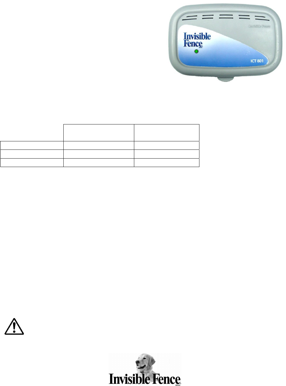
The ICT 801, ICT 802, and ICT 810
Transmitters are used as part of an Invisible
Fence® Brand pet containment system. These
transmitters must always be installed in a dry,
protected area to insure they will not be
exposed to the elements.
The transmitters are connected to an external signal field wire and send a coded, digital
signal along the entire length of wire. The following wire specification should be
followed:
ICT 801 / ICT 802
Up to 3,000 ft.
ICT 810
Up to 5,000 ft.
Feet of twisted pair 150 feet 200 feet
Wire size 14 AWG 12 AWG *
Jacket PE .045” PE .045”
*12 AWG is recommended, however, it may require a pigtail to 14 AWG for insertion
into the LP-4100 or LP-4200 connectors.
The ICT 801 and ICT 802 are programmable to transmit a digital signal either at 7KHz
or at 10KHz, whereas the ICT 810 transmits only a 7KHz digital signal. The ICT 801,
ICT 802, and ICT 810 Transmitters are only compatible with the R21 v4.0 Titanium
Computer Collar®. All ICT 801, ICT 802, and ICT 810 Transmitters have removable
circuit boards that can be replaced if damaged.
Planning the Installation
Install the transmitter in a dry indoor location, near a grounded 110VAC electric outlet
that offers easy access to the outdoors. A garage or basement is usually the best
location. If you are not sure the intended outlet is grounded, use a 3-wire circuit
analyzer or contact an electrician. To fasten the transmitter base to the wall, you
need four ¾ inch long (19mm), #8, or #10 pan-head sheet metal screws.
Caution: Never install a system or equipment, or service any equipment, during a
thunderstorm or electrical storm, or when thunder or lightning is in your area.
3
Connecting the Signal Field Wire
All Invisible Fence® Brand Pet Containment Systems must be grounded per
the NATIONAL ELECTRICAL CODE (NEC) to be protected against lightning.
ICT 801, ICT 802, and ICT 810 Transmitters must be installed using the LP-4100
(ICT 801 and ICT 810) or LP-4200 (ICT 802) Lightning Protection devices in
accordance with the NEC and applicable local building codes.
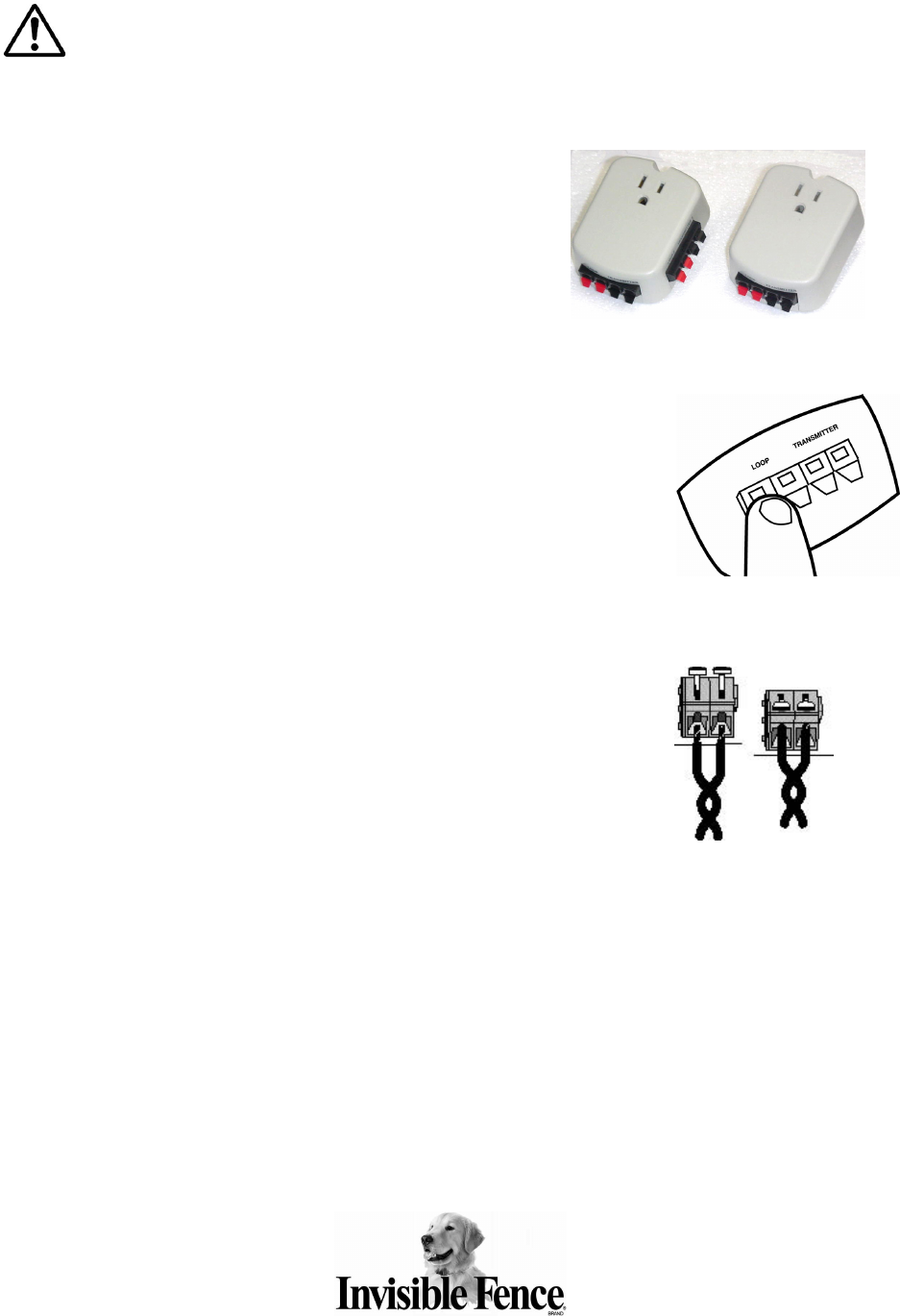
1. Strip approximately ¼ inch (6.3mm) of insulation
from each end of the signal field wires (in-ground
containment loop). Using your finger, depress the
tab of one red connector (marked LOOP) on the
Lightning Protector. Insert one stripped end of the
signal field wire into the red connector hole.
Release the tab. Repeat for the remaining signal
field wire. Note: Insert only one wire per hole.
2. Next, connect the ICT 801, ICT 802, or ICT 810 transmitter
to the LP-4100 or LP-4200 with a short length of twisted
pair wire. Strip approximately ¼ inch (6.3mm) of insulation
from each end of the twisted pair wires. Insert one of the
twisted pair transmitter wires into a black connector hole
(marked TRANSMITTER) of the LP-4100 or LP-4200 in the
same manner as the signal field wires connected in step #1.
Repeat for the remaining twisted pair wire. (Remember —
insert only one wire per hole)
3. Connect the other end (stripped the same way as in step #2)
of the twisted pair wires to the transmitter via the signal field
connectors. Use your thumb to push back on the white tabs
located on top of the signal field wire connectors. While
pushing back the tabs, put the end of each wire into each
opening of the connectors. Hold the wires steady, and
release the tabs.
4. Before plugging in the LP-4100 or LP-4200, make sure the electric outlet is properly
grounded. Remove the plastic cover that protects the plug on the LP-4100 or LP-
4200 and plug it into a grounded 3-prong household outlet (110VAC) within five feet
(5’) of where you wish to install the transmitter. When possible, use the center screw
that holds the outlet cover plate in place. If this screw is missing or not long enough,
use the longer screw provided with the Lightning Protector. NOTE: This screw is for
mechanical attachment only and does NOT provide electrical ground!
Instructions are continued on the next page…
LP-4200 LP-4100
4
5. Plug the transmitter power AC adapter into the 3-prong socket in the LP-4100 or LP-
4200.
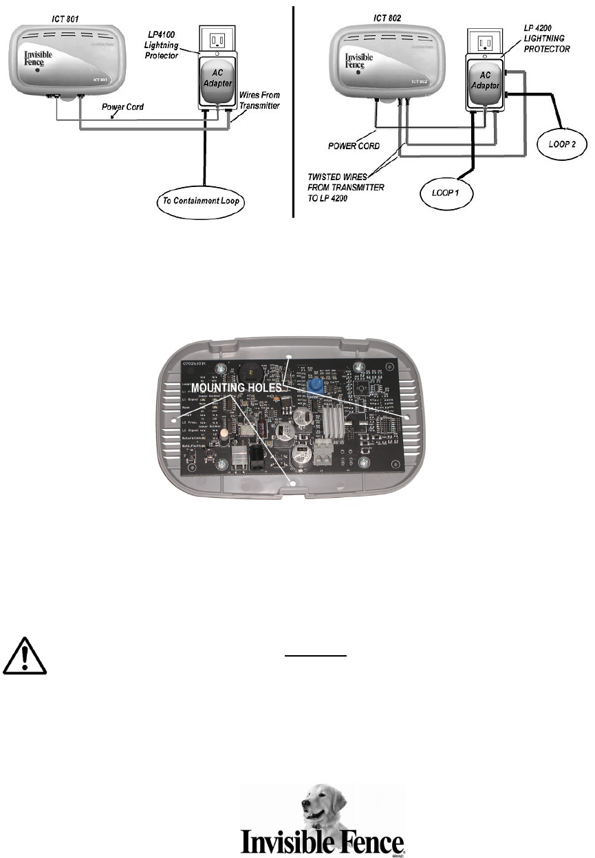
6. Install the transmitter base to the wall using four ¾ inch long (19mm), #8, or #10
pan-head sheet metal screws. Insert the screws through the four mounting holes
(shown below) in the base of the transmitter case.
NOTE: The Invisible Fence® Brand system and the LP-4100/LP-4200 will function properly in a GFCI
outlet. In rare cases, lightning strikes or overload fault conditions may cause the GFCI to trip. You
must instruct the homeowner to reset the tripped CFCI outlet in order for the Invisible Fence® Brand
system to function properly.
IMPORTANT NOTE: Always use a grounded 3-prong 110VAC outlet with the LP-4100/LP-
4200 in order to ensure maximum lightning surge protection. Please note that removing
the center ground pin from an LP-4100/LP-4200 will void the warranty. This product must always be
located in a dry, protected area where it will not be exposed to the elements. For installations with
ungrounded, 2-prong 110VAC outlets, refer to Technical Bulletin #0204 – Procedure for Grounding
LP-4000 Series Module.
5
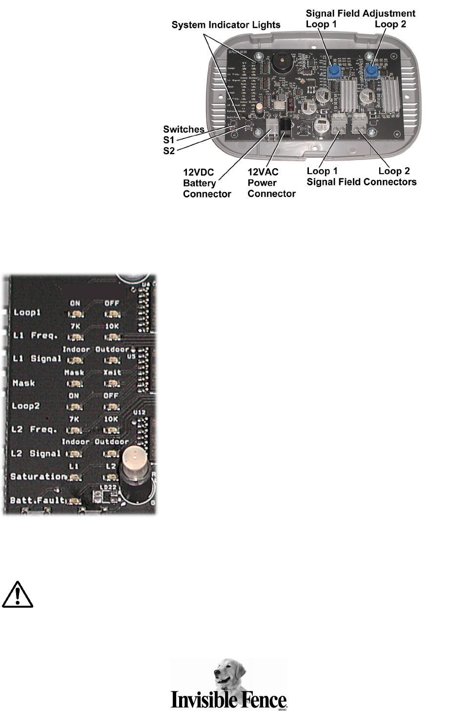
ICT 801
Transmitter
The ICT 801 is a single
loop programmable
transmitter designed for
installations with up to
3,000 feet of signal field
wire and up to 150 feet
of twisted pair wire. The
ICT 801 has one signal
field adjustment to
increase or decrease
the width of the signal
field. See page 11 for
instructions for setting
the signal field width.
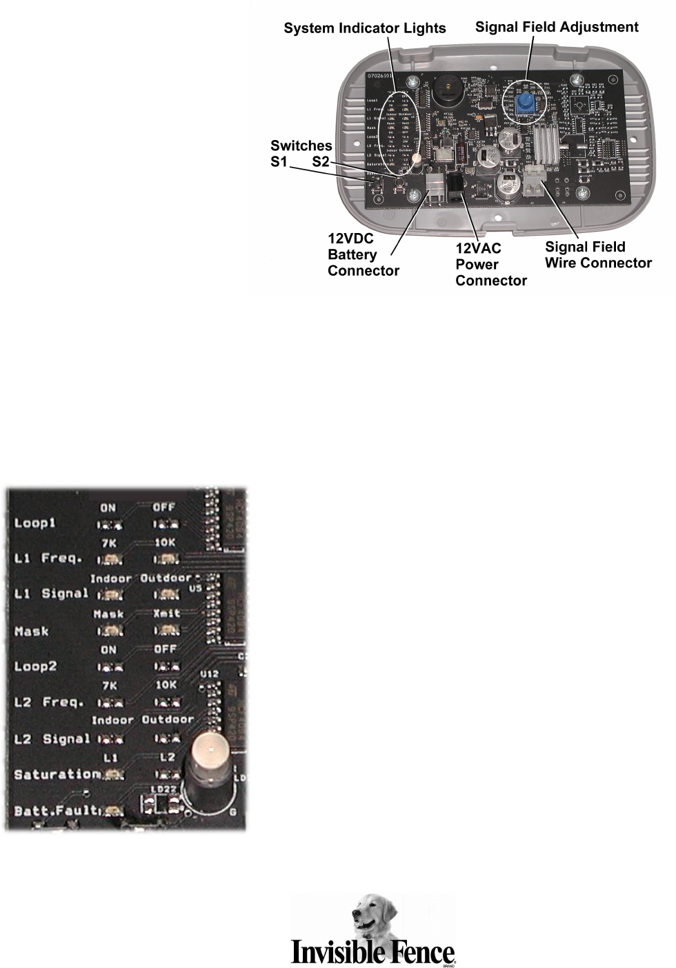
User Settings and Functions for ICT 801 Transmitter:
Loop 1: Loop 1 is always functioning on the ICT 801. (No indicator
light on the circuit board.)
L1 Freq.: Select either 7K or 10K signal for Loop 1. The default setting
is 7K.
L1 Signal: Select either Indoor or Outdoor mode for Loop 1. The
default setting is Outdoor.
Mask: Select either Mask or Xmit to transmit a mask or boundary
signal for Loop 1. The default setting is Xmit.
Saturation: Indicates Loop 1 transmitter output saturation. Loop
saturation exists when the signal has reached maximum output level,
which is caused by excessive loop size, excessive resistance, or poor
connections.
Batt. Fault: Indicates when 12VDC backup battery is not installed or
not working properly.
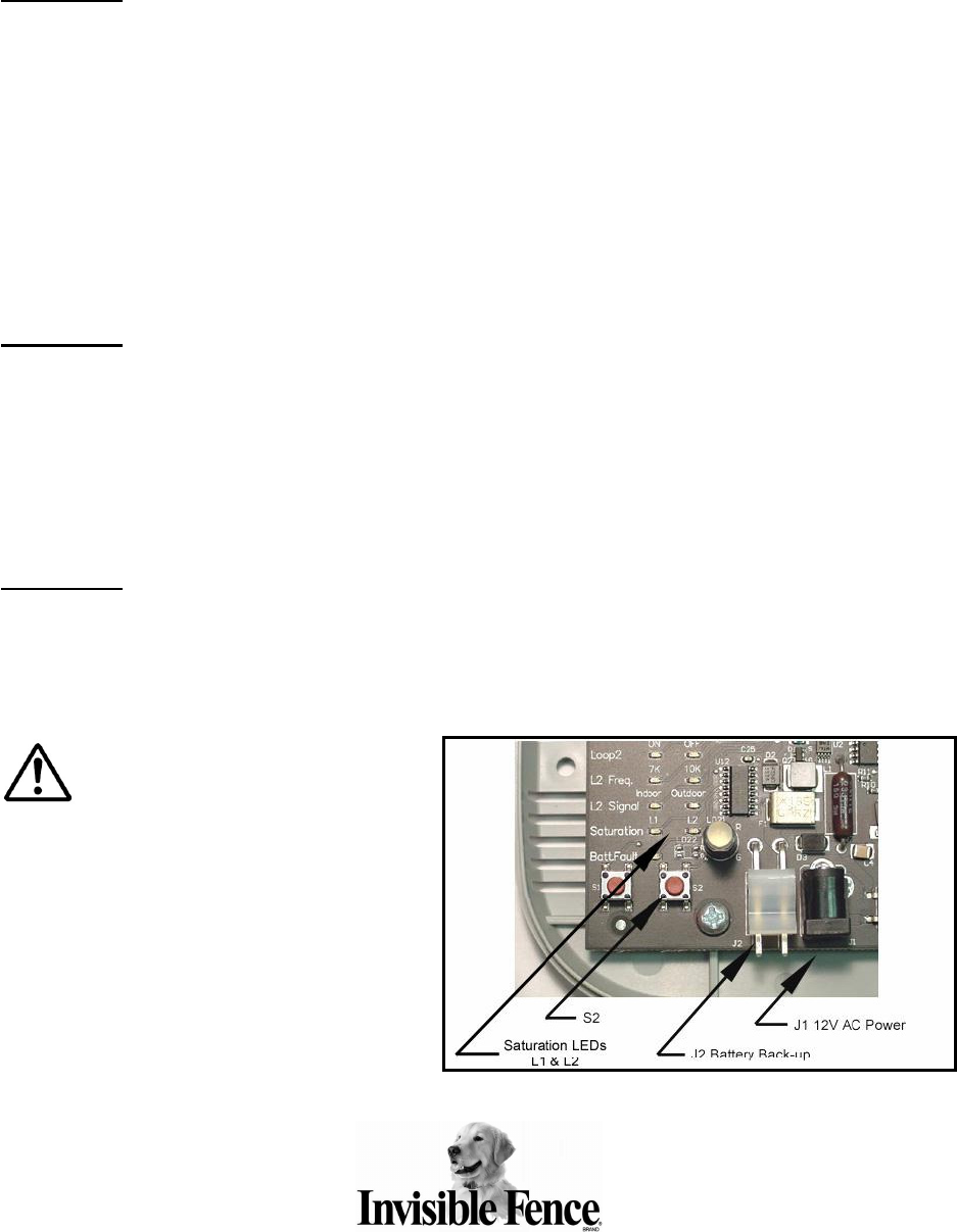
System Indicator Lights
6
ICT 802 Transmitter
The ICT 802 is a dual loop
programmable transmitter.
Each loop on the ICT 802 can
have up to 3,000 feet of loop
wire and up to150 feet of
twisted pair. Signal width for
each loop can be adjusted by
using the signal field
adjustments for Loop 1 and
Loop 2.
See page 11 for instructions
for setting the signal field
width.
User Settings and Functions for ICT 802 Transmitter:
Loop 1: Used to turn Loop 1 LED circuitry ON or OFF. If OFF is
selected, all LEDs for Loop 1 will not light.
L1 Freq.: Select either 7K or 10K signal for Loop 1. The default
setting is 7K.
L1 Signal: Select either Indoor or Outdoor mode for Loop 1. The
default setting is Outdoor.
Mask: Select either Mask or Xmit to transmit a mask or boundary
signal for Loop 1. The default setting is Xmit.
Loop 2: Used to turn Loop 2 LED circuitry ON or OFF. If OFF is
selected, all LEDs for Loop 2 will not light.
L2 Freq.: Select either 7K or 10K signal for Loop 2 if the loop is
ON.
L2 Signal: Select either Indoor or Outdoor mode for Loop 2 if the
loop is ON.
Saturation: Indicates Loop 1 and/or Loop 2 transmitter output
saturation. Loop saturation exists when the signal has reached
maximum output level, which is caused by excessive loop size,
excessive resistance, or poor connections.
Batt. Fault: Indicates when 12VDC backup battery is not installed
or not working properly.
Important: When using Loop 1 of the ICT 802 transmitter as a Mask, remember to adjust
the Mask signal appropriately. Make sure the Mask signal is not radiating further than the
actual signal bleed it is masking. To measure the Mask field, turn off the containment loop, change
the Mask loop back to transmit mode (Xmit), and measure the signal field with a R21 v4.0 receiver
where the Mask is placed. Change the loop back to Mask mode when finished.
System Indicator Lights
7
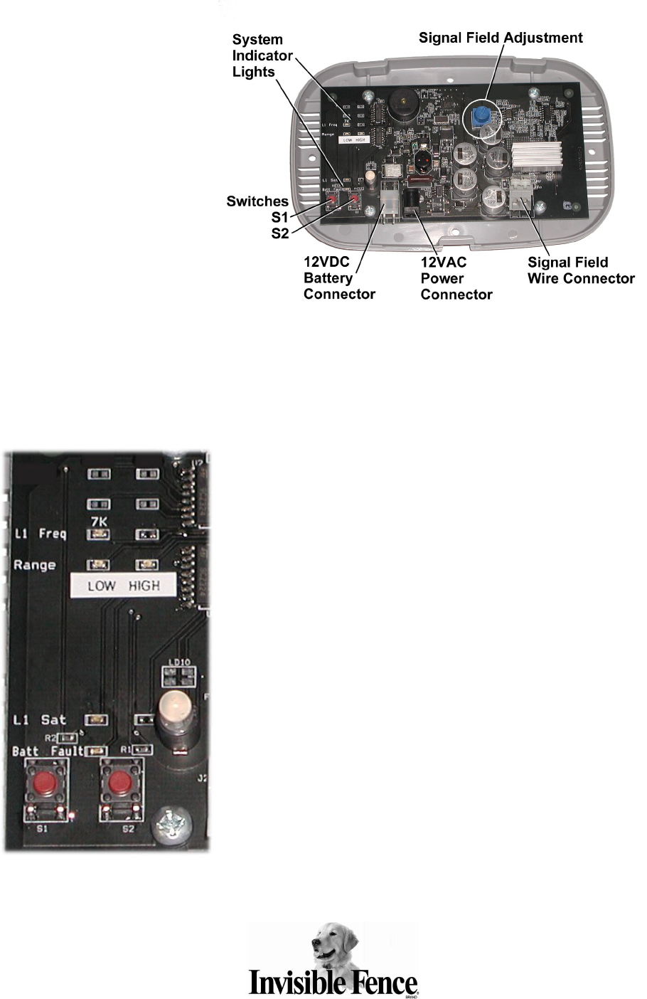
ICT 810 Transmitter
The ICT 810 is a single loop
programmable transmitter
designed for installations
with up to 5,000 feet of
signal field wire and up to
200 feet of twisted pair wire.
The ICT 810 has one signal
field adjustment to increase
or decrease the width of the
signal field. See page 11 for
instructions for setting the
signal field width.
User Settings and Functions for ICT 810 Transmitter:
L1 Freq.: ICT 810 is always set to 7K.
Range: ICT 810 range can be set to LOW or HIGH. This setting
adjusts the sensitivity of the signal field adjustment knob. Using the
LOW range setting allows for smaller signal field setting while the
HIGH range setting will create a larger signal field.
L1 Sat: Indicates Loop 1 transmitter output saturation. Loop
saturation exists when the signal has reached maximum output
level, which is caused by excessive loop size, excessive resistance,
or poor connections.
Batt. Fault: Indicates when 12VDC backup battery is not installed
or not working properly.
System Indicator Lights
8
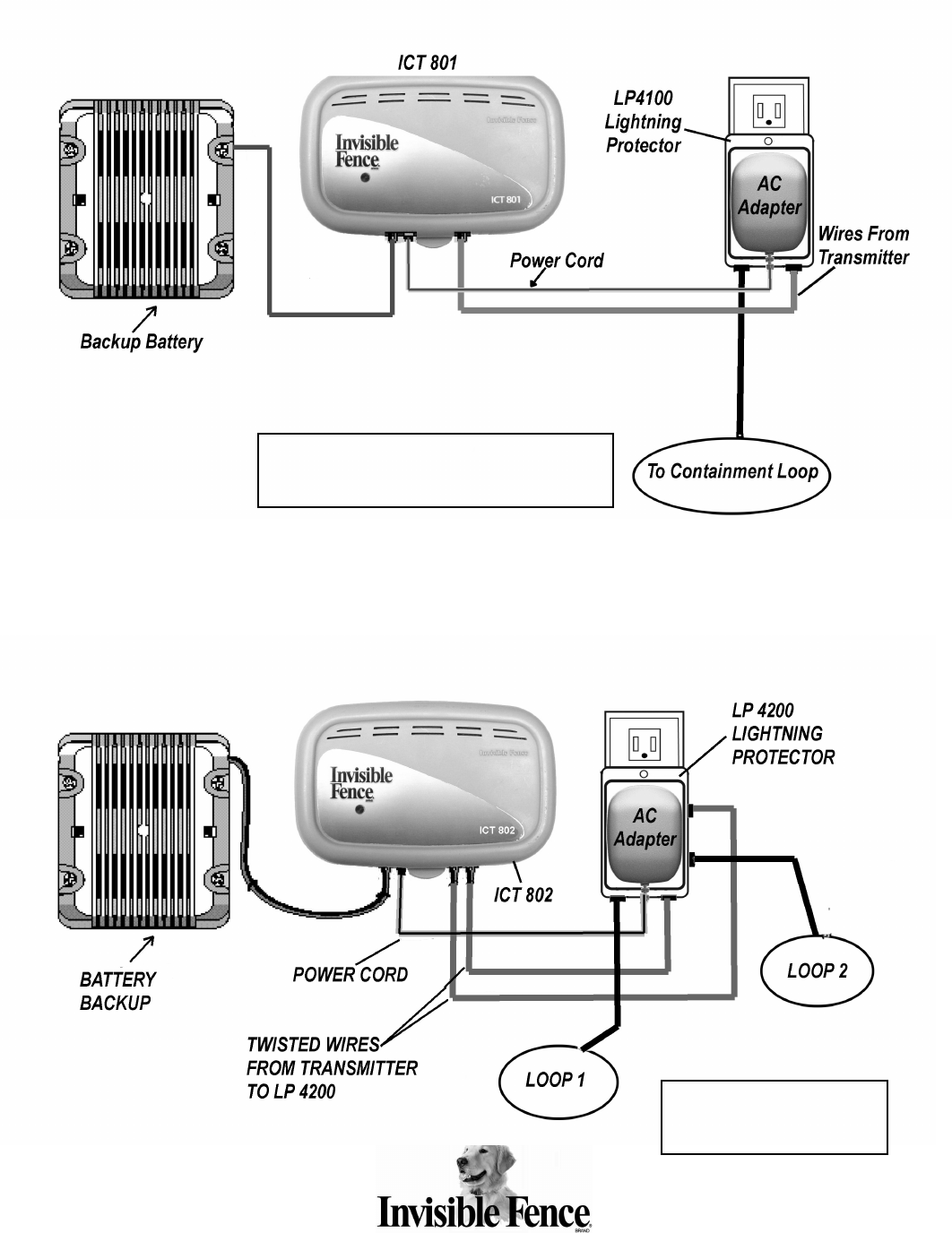
Typical ICT 801 and ICT 810 Installation
Typical ICT 802 Installation
P
Pr
ro
og
gr
ra
am
mm
mi
in
ng
g
t
th
he
e
I
IC
CT
T
8
80
01
1,
,
I
IC
CT
T
8
80
02
2,
,
a
an
nd
d
I
IC
CT
T
8
81
10
0
T
Tr
ra
an
ns
sm
mi
it
tt
te
er
rs
s
ICT 801: loop can be up to 3000 feet long
ICT 810: loop can be up to 5000 feet long
ICT 802: each loop can be
up to 3000 feet long
9
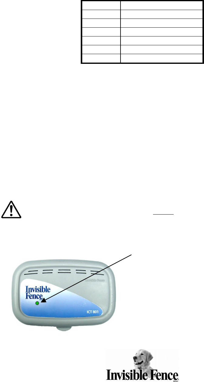
Programming the ICT 801, ICT 802, and ICT 810 Transmitters
On first time power up, the LED status indicator lights will display the following default
settings.
Indicator Default Setting
Loop 1 ON
L1 Freq. 7K
L1 Signal Outdoor
Mask Xmit
Loop 2 Off (for 802 model only)
Range LOW (for 810 model only)
Once the transmitter has been programmed, the settings will remain in the system
memory. To program the transmitter:
1. Press and hold the S1 button for approximately 4 seconds until
a. For ICT 801: The L1 Freq. LED begins to blink.
b. For ICT 802: The Loop 1 LED begins to blink.
c. For ICT 810: The Range LED begins to blink.
2. Release the S1 button.
3. Momentarily press and release the S2 button to toggle between each setting
option.
4. Press and release the S1 button to move to the next setting.
5. Continue until all choices are selected.
6. The cursor LED will stop blinking approximately ten seconds after the buttons are
released, and the transmitter will automatically exit the programming mode.
IMPORTANT: If the transmitter is disconnected from the power source while the status
indicator lights are still blinking, the settings will not be saved to the
system memory.
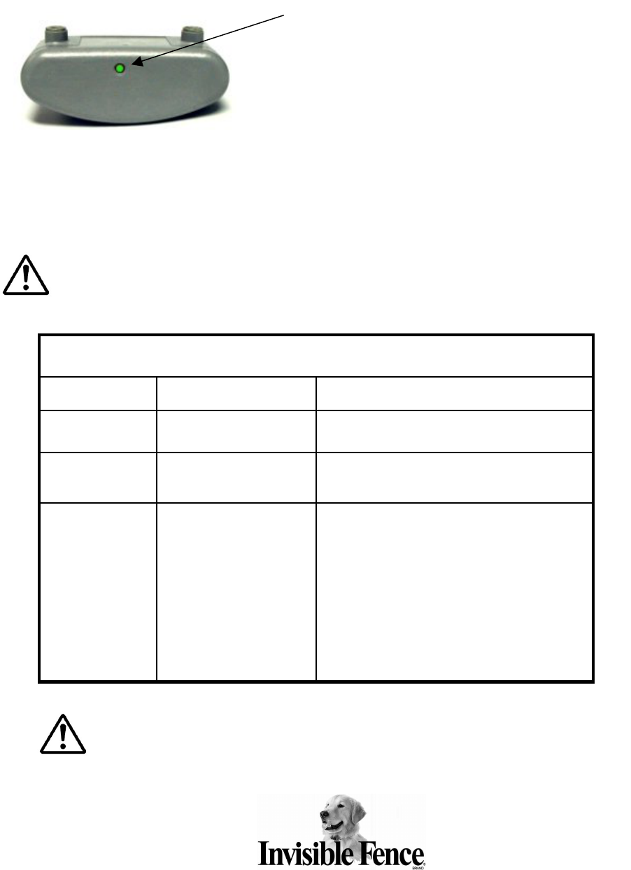
LED Status Indicator Light: This is the only visible light from outside of the enclosure when the cover is
closed.
LED Status Indicator Light
Audible Alarm: There is an audible alarm for
certain alert conditions (See table on page
10). Press and release either the S1 or the S2
button on the circuit board to silence the
alarm. The alarm will re-activate on power-up,
or when exiting set-up mode (if a failure
condition still exists).

10
Primary power: Primary power to the unit shall be provided by:
ICT 801 Transmitter: AC Adapter Model 100-0020-01
ICT 802 Transmitter: AC Adapter Model 100-0018-01
ICT 810 Transmitter: AC Adapter Model 100-0018-01
Backup Battery power: The ICT 801, ICT 802, and ICT 810 Transmitters can continue to
function in the event of a power outage when connected to a fully charged backup
battery system. A fully charged 12VDC battery with a 5.0Ah (Amp hours) rating provides
enough power to the system for approximately 10 hours with the signal field set to the
maximum width. Conversely, the narrower the signal field is set, the longer the battery
will continue to power the system.
Invisible Fence® Brand Backup Battery Model 10-900-0040-01 must be used.
The ICT 801, ICT 802, and ICT 810 Transmitters are designed so the battery backup
system is not necessary for normal operation. If a backup battery is not installed, the
Batt. Fault system indicator LED on the transmitter circuit board will be ON.
IMPORTANT: The recommended battery has a limited shelf life and should be replaced
every five years. The approved 5.0Ah battery (Model 10-900-0040-01) will take up to 50
hours to charge to full power.
• Chirp every 5 seconds
(Can be silenced by pressing S1 or
S2 button)
• Steady red light
RED
Defective backup battery
• Constant beeping (Can be silenced
by pressing S1 or S2 button)
• Steady red light
RED
Loop wire break or
decrease in signal field
• Chirp every 5 seconds
(Can be silenced by pressing S1 or
S2 button)
• Slow red flash
• 1 second on, 4
seconds off
RED
AC Failure
(Only if optional Backup
Battery is installed)
• None
• Slow green flash
• 1 second on, 4
seconds off
GREEN
System OK
A
Au
ud
di
ib
bl
le
e
A
Al
le
er
rt
t
I
In
nd
di
ic
ca
at
to
or
r
L
LE
ED
D
C
Co
ol
lo
or
r
S
St
ta
at
tu
us
s
I
I
C
C
T
T
8
8
0
0
0
0
S
S
e
er
r
i
ie
es
s
–
–
S
S
t
ta
at
tu
u
s
s
L
Li
ig
g
h
ht
t a
an
nd
d
A
Au
u
d
d
i
ib
bl
le
e A
Al
la
ar
r
m
m T
Tr
r
o
ou
u
b
bl
le
es
sh
ho
oo
ot
ti
in
ng
g

11
Setting the Signal Field Width
The signal field width is what activates the R21 v4.0 Titanium Computer Collar®. The
signal field can be set to various distances from the signal field wire. The distance from
the wire loop to the edge of the signal field is called the signal field width.
There is one signal field adjustment knob on ICT 801 and ICT 810 transmitters and two
signal field adjustment knobs on the ICT 802 transmitter. See page 5, 6, or 7 as
appropriate for location of signal field adjustment knobs. Turning the signal field
adjustment knob clockwise increases the signal field width. Conversely, turning it
counter-clockwise decreases the signal field width.
IMPORTANT: These adjustments do not change the correction level of
the Invisible Fence® Brand R21 v4.0 Titanium Computer Collar® receiver,
it only changes the width of the signal field.
You can check the width of the signal field
by holding the Invisible Fence® Brand
R21 v4.0 Titanium Computer Collar®
receiver so that it is parallel to the signal
field wire. Hold the collar so the receiver
is about the same height and at the same
angle as it will be when the pet is wearing
it. Walk slowly toward the signal field wire.
The receiver will activate when it is at the
edge of the signal field.
IMPORTANT: Invisible Fence® Brand R21 v4.0 Titanium Computer Collar®
receivers have a fail-safe mechanism. Should the pet become caught in the signal
field, the receiver will go through three cycles of 10 seconds ON, 10 seconds
OFF, and then shut down. The collar will not reactivate until it is completely
removed from the signal field, and then brought back into it.
12
Setting the Break-Alert® Detection Level:
The Break Alert® alarm can be set to make a sound when the signal field width is
reduced by 25% or more of the set signal field width.
Read entire procedure before performing. Only the loops turned on will be
programmed.
Option #1: To set the Break Alert® to activate when a 25% reduction in set signal field
width occurs:
1. Set the signal field width for desired system operation.
2. If battery backup is being used, remove 12VDC battery power wire harness from transmitter
connector J2 (see picture below).
3. Remove 12VAC power from transmitter connector J1.
4. Press and hold S2 button while reconnecting 12VAC power back to transmitter connector
J1.
5. Continue holding S2 button for approximately five more seconds.
6. Release S2 button.
7. Break Alert® levels are now set. Setting will remain in memory even after power is removed.
8. Reconnect battery backup wire harness to transmitter connector J2, if applicable.
Option #2: To set the Break Alert® to activate at more than a 25% reduction in set
signal field width:
1. Set the initial signal field width to the desired operational signal field width. Note the position
of the indicator on the adjustment device.
2. Now adjust the signal field width to less than the desired operational signal field width.
3. Complete steps 2 – 6 under Option #1.
4. Adjust the signal field width to the desired operational field width.
5. Break Alert® levels are now set. Setting will remain in memory even after power is removed.
Option #3: To set the Break Alert® level back to the default settings (less than 1 foot).
1. Set the signal field width to the lowest setting (turn signal field adjustment all the way
counterclockwise).
2. Complete steps 2 – 6 under Option #1.
3. Set the signal field width to the desired operational field width.
4. Break Alert® levels are now set. Setting will remain in memory even after power is removed.
IMPORTANT: During a wire break,
the alarm sounds and the
Saturation LED L1 and/or L2 will light to
notify which loop the break is on. The
alarm will also sound if the signal field
adjustment setting is below the
programmed Break Alert® level.
13
R21 v4.0 Titanium Computer Collar® Receiver
Invisible Fence® Brand Computer Collar® receivers are microprocessor-controlled units
powered by a Power Cap® battery .
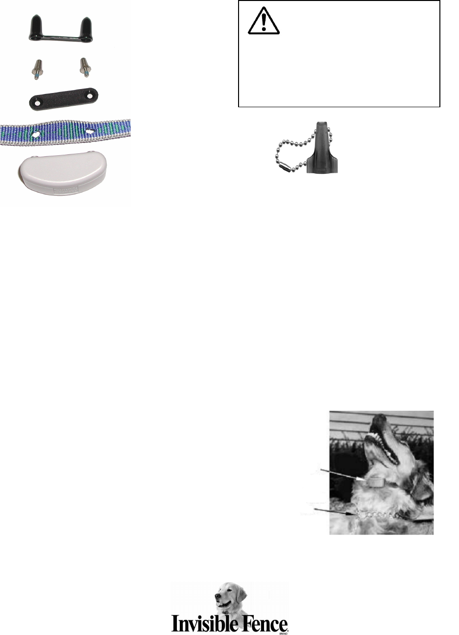
Fitting the Invisible Fence® Brand Titanium Computer Collar® receiver on the Pet:
To work properly, the correction posts on the Invisible Fence® Brand Computer Collar®
receiver must touch the pet’s skin.
1. Position the Invisible Fence® Brand Computer Collar® receiver high up on the pet’s
neck with the receiver under its lower jaw.
2. To avoid having a collar that is too tight on a thick-haired pet, thin some hair away to
make skin contact with the correction posts. DO NOT shave the pet’s neck.
3. Tighten the strap of the Invisible Fence® Brand Computer Collar® receiver
appropriately. Adjust the collar so it is snug enough to slide one finger between the
correction post and the pet’s neck.
4. The fit of the Invisible Fence®
Brand Computer Collar® receiver
should be adjusted as necessary
as the pet’s coat, weight, and age
change.
5. Allow the pet to become
accustomed to its new Invisible
Fence® Brand Computer Collar®
receiver. The collar should be
removed each night during the first
month of training and regularly
thereafter. This ensures proper fit and avoids the possibility of skin irritation from the
correction posts.
Correction Post Covers
Correction Posts
Retaining Strip
Collar Strap
R21 v4.0 Titanium
Computer Collar® Receiver
ALWAYS use the post-tightening
tool to tighten the receiver correction posts.
DO NOT secure the correction posts to the
Invisible Fence® Brand Computer Collar®
receiver with any kind of glue or adhesive.
Post-Tightening Tool
Slip or
Woodhouse collar
is only used during
training.
Compute
r
Colla
r
®
14
Invisible Fence® Brand R21 v4.0 Titanium Computer Collar®
Power Cap® Battery Status:
The ICT 801, ICT 802, and ICT 810 Transmitters utilize the R21 v4.0 Titanium
Computer Collar® receiver. This receiver monitors Power Cap® battery status and will
alert the owner when the Power Cap® battery needs to be replaced. A Power Cap®
battery test is also performed each time it is inserted into the Computer Collar® receiver.
When the Power Cap® battery is inserted:
The LED status indicator shows GREEN for up to 1 second while testing, and then
blinks (4 times) one of the following 3 colors to indicate the Power Cap® battery status:
• GREEN = Power Cap® battery is good.
• YELLOW = Replace the Power Cap® battery.
• RED = Replace NOW! Do not rely on the Invisible Fence® Brand system to
contain the pet. The owner must become familiar with the Power Cap®
battery status indicators.
For detailed instructions on how to program the R21 v4.0 Titanium Computer Collar®
receiver, please refer to the CF-2200 Programming Tool Manual.
LED Status Indicator
(Top view of R21 v4.0 Titanium Computer Collar® receiver)
• DO NOT RELY ON THE INVISIBLE
FENCE® BRAND SYSTEM TO KEEP
THE PET CONTAINED!
• Replace the Power Cap®
• When a replacement Power Cap® is
installed and signal field checked, the
Invisible Fence® Brand System is
ready for pet containment.
Power Cap® is dead
Flashing Red
• Replace Power Cap® - The Power
Ca
p
®has lost most of its
p
ower.
Power Cap® is low
Flashing Yellow
• No Action Required
Power Cap® is good
No light
Action Required Condition LED Indicator
R21 v4.0 Titanium Computer Collar® Status Light Indicator
15
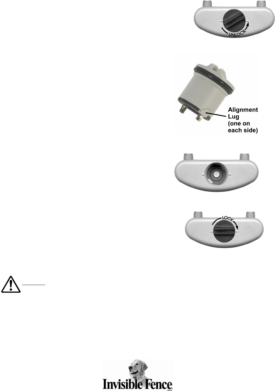
Changing the Power Cap® Battery:
1. Use a small, thin coin to remove the Power Cap® battery
from the R21 v4.0 Titanium Computer Collar® receiver.
Insert the coin in the slot on top of the Power Cap®
battery and turn it counter-clockwise. Do not push
down while turning. The Power Cap® battery will rotate
up and out of the R21 v4.0 Titanium Computer Collar®
receiver’s battery chamber.
2. Install a new Power Cap® battery using the following
steps:
a. Line up the lugs on each side of the bottom of
the Power Cap® battery with the grooves in the
sides of the R21 v4.0 Titanium Computer
Collar® receiver’s battery chamber. Make sure
the metal tabs on the bottom of the Power
Cap® battery are not bent.
b. Place the Power Cap® battery into the chamber
while gently, but firmly, turning it clockwise with
your fingers.
c. Use a small, thin coin in the slot on top of the
Power Cap® battery to turn it clockwise until the
slot on the top of the Power Cap® battery is
lined up with the two small raised tabs on the
bottom of the receiver. Do not over tighten
by turning the slot past the tabs on the
receiver.
On average, the Power Cap® battery should be
changed every 3 months. Low temperatures, the
number of times the pet challenges the system
boundary, and improper collar fit can all reduce Power
Cap® battery life.
Warning: The use of any power source other than a Power Cap®
battery will cause the receiver to operate erratically or fail. Failure of the receiver due to the
use of an unauthorized power source will result in denial of a warranty claim.
The use of unnecessary force may damage the case and render the Power Cap® battery inoperable.
NEVER open a Power Cap® battery, dispose of it in fire, recharge it, heat it above 212°F (100°C), or
expose its contents to water. Doing so can cause leakage or explosion and may lead to personal
injury.

FCC ID# KZ3050261 “This device complies with Part 15 of the FCC Rules. Operation is subject
to the following two conditions: 1) This device may not cause harmful interference, and 2) This
device must accept any interference received, including interference that may cause undesirable
operation. Changes or modifications not expressly approved by the party responsible for
compliance could void the user’s authority to operate the equipment.”
INDUSTRY CANADA CERTIFIED
Canada 2430A-050261
© 2005 Invisible Fence, Inc., 1000 Fuller Drive, Garrett, IN 46738
0405 2100289-1
Printed in USA. All rights reserved.