Radio Systems 3001183 INVISIBLE FENCE BRAND DOORMAN User Manual
Radio Systems Corp INVISIBLE FENCE BRAND DOORMAN Users Manual
Users Manual

Invisible Fence® Brand Doorman™
Electronic Pet Door
Operating Guide
Model Numbers: RAC00-13211
Please read this entire guide before operating.
Important Safety Information
Explanation of Attention Words and Symbols used in this guide
This is the safety alert symbol. It is used to alert you to potential personal injury hazards.
Obey all safety messages that follow this symbol to avoid possible injury or death.
WARNING indicates a hazardous situation which, if not avoided, could result in death or
serious injury.
CAUTION, used with the safety alert symbol, indicates a hazardous situation which, if
not avoided, could result in minor or moderate injury.
NOTICE is used to address safe use practices not related to personal injury.
WARNING
• When children are present in the home, it is important to consider the pet door
during child proofing activities. The pet door may be misused by a child resulting
in the child accessing potential hazards that may be on the other side of the pet
door.
• Purchasers/Homeowners with swimming pools should ensure that the pet door is
monitored at all times and that the swimming pool has adequate barriers to entry.
If a new hazard is created inside or outside of your home, which may be
accessed through the pet door, Invisible Fence® Brand recommends that you
properly guard access to the hazard or remove the pet door.
• The closing panel or lock, if applicable, is provided for aesthetic and energy
efficiency purposes and is not intended as a security device. Invisible Fence®
Brand will not be liable for unintended use and the purchaser of this product
accepts full responsibility for oversight of the opening it creates.
CAUTION
• The user, prior to installation, must become familiar with all building codes that
may affect the installation of the pet door and determine, along with a licensed
contractor, its suitability in a given installation.
• This pet door is not a fire door. It is important for the owner and contractor to
consider any risks that may be present inside or outside of the pet door, and any
risks that may be created by subsequent changes to your property and how they
may relate to the existence and use, including misuse of the pet door.
NOTICE
• Keep these instructions with important papers; be sure to transfer these
instructions to the new owner of the property.
• Unauthorized changes or modifications may void the user’s authority to operate
this equipment, and void the warranty.
Thank you for choosing the Invisible Fence® Brand Doorman™. You and your pet
deserve a companionship that includes memorable moments and a shared
understanding together. Our products and training tools promote a lifestyle of protection,
teaching, and love—essentials that influence memories for a lifetime. If you have any
questions about our products or training your pet, please visit our website at
www.invisiblefence.com or contact your local dealer.
______________________________________________________________________
Table of Contents
How the Invisible Fence® Brand Doorman™ Electronic Pet Door Works
Invisible Fence Doorman - Controls and Features
1.1 Input & Output Controls
1.2 Features
XXXXX
XXXXX
XXXXX
XXXXX
XXXXX
How the Invisible Fence® Brand Doorman™ Electronic Pet Door Works
Using radio-frequency technology, the Invisible Fence® Brand Doorman™ Electronic Pet
Door reads the Computer Collar® SmartLink™ II code and triggers a battery power-
driven flap to unlock so your pet(s) can come and go as they please. When Invisible
Fence® Brand Doorman™ Electronic Pet Door no longer senses your pets’ SmartLink™ II
code, the flap automatically locks back into place. The Invisible Fence® Brand
Doorman™ Electronic Pet Door can detect up to five programmed SmartLink™ II codes
and also operates in two other modes: locked mode and unlocked mode.
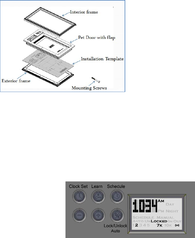
Components
Invisible Fence® Brand Doorman™ - Controls and Features
1.1 Input & Output Controls
Input:
Push Buttons:
There are 6 pushbutton switches available for a user to control the various functions
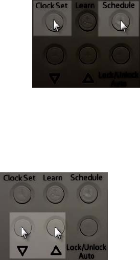
and settings of the door. The buttons are shown below in Figure 1.
Figure 1: Pushbuttons for Controlling Door Functionality
Going from left-to-right, top-to-bottom, the buttons are called
(1) Clock Set
(2) Learn
(3) Schedule
(4) Down
(5) Up
(6) Lock/Unlock/Auto
Wireless (RF):
The pet door has the ability to receive wireless radio frequency (RF) signals. Some
functions, such as the Learn function, utilizes wireless signals to read new transmit
codes associated with the Computer Collar®.
Output
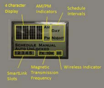
LCD Display:
The LCD Display is used to show various settings and information about the door. It is
comprised of various LCD segments that can be activated or deactivated. These fields
are black when turned-on and can’t be seen when turned-off. Figure 2 below shows all
possible segments that may be on at any given time.
Figure 2: LCD Display
Upon power-up, all segments that are used will be turned-on for 1 second and then
turned-off for 0.5 seconds. This feature is used to verify on and off functionality of all
relevant LCD segments.
Sound: The door contains a speaker that is capable of generating an audible tone.

Signal Activation Technology: Technology that allows activation communication to
occur between the pet door and the Computer Collar® within an adjustable range area.
1.2 Features
The Invisible Fence® Brand Doorman™ contains a variety of features and abilities that
can be controlled and configured by users. By utilizing the pet door’s Input and Output
Control capabilities a user may:
‐ Set the Clock
‐ Learn SmartLink™ II Code(s)
‐ Display SmartLink™ II Slots in Use
‐ Establish a Schedule
‐ Turn Scheduling On or Off
‐ Set Signal Activation Range
‐ Switch between Locked, Unlocked and Automatic modes
‐ Change frequencies settings between 7K and 10K
‐ Lock Pushbuttons to prevent tampering/adjustments
‐ View Low Battery Indicator.
Setting the Clock:
Upon powering-up the pet door, the LCD clock defaults to 12:00 AM. The clock must be
set each time the batteries are replaced.
Buttons used in setting the Clock are the Clock Set, Learn, Down and Up buttons
Press and hold the Clock Set button until the hours digits begin blinking.
Use the Down and Up arrow buttons to adjust the hour to the appropriate time. When
adjusting the hour, it will “roll-over” automatically from AM to PM .

Pressing the Clock Set button again will cause the minute digits to blink. The Down and
Up buttons are used to adjust the minutes field to the appropriate time. When the
correct time is displayed, press the Learn button to save the desired time.
Learn SmartLink™ II Code(s):
Each Computer Collar® is configured with a SmartLink™ II code. The code will be preset
to codes between 10 and 19. Utilizing the CF-3000 Dealer Tool, the code can be
changed to any number between 1 and 31. The CF-3000 Dealer Tool can be used to
configure multiple Computer Collars® with the same SmartLink™ II code.
Invisible Fence® Brand Doorman™ is capable of learning five different SmartLink™ II
codes.
The following section describes how an Invisible Fence® Brand Doorman™ can Learn
up to five different SmartLink™ II codes.
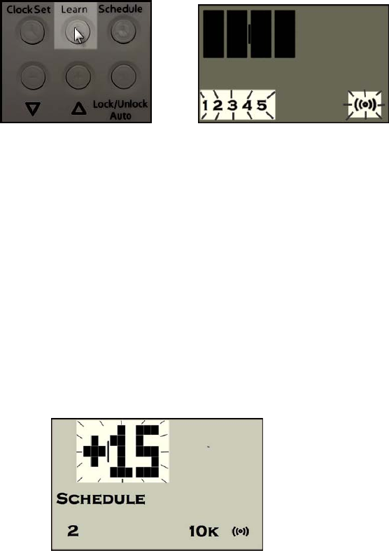
Buttons used for the Learn function are the Learn, Schedule, Down and Up buttons.
The LCD Segments utilized in the Learn function include the hour and minute indicators,
the 1 – 5 slot indicators and the Wireless indicator. The slot numbers represent the
number of SmartLink™ II codes that are stored. The Wireless symbol will blink each time
data or the SmartLink™ II code is transmitted or received wirelessly.
Press and hold the Learn button for 2 seconds to enter Learn mode. One of the 5
numeric SmartLink™ II slots and the Wireless symbol will begin to blink on the LCD
Display. The first empty slot (number 1 of 5) will be used to store the SmartLink™ II code.
If all slots are full and a new code is stored, the new code will overwrite the code
currently stored in the first slot. If a duplicate SmartLink™ II code is received, its slot is
automatically selected and no additional empty slots are used.
There are two methods that can be utilized to instruct the pet door what SmartLink™ II
code to learn:
1) A Computer Collar® can be brought within proximity to the pet door after
entering the Learn mode
2) The Down and Up buttons may be used to manually set the SmartLink II code
that is stored in the selected slot.
Utilizing Method (1), the ‘+’ sign will appear along with the numeric SmartLink™ II code
when any SmartLink™ II code is received wirelessly. It will become blank if the transfer
of data does not occur or when it does not receive one successfully.
Method (2) is useful in situations where the SmartLink™ II code of a Computer Collar® is
known beforehand.
In using either method, the right-most 3 characters of the LCD display will show the
numeric SmartLink™ II code that occupies the selected slot.
After all applicable SmartLink™ II codes have been Learned, the Schedule button can
be pressed to save the changes. Alternatively, changes are saved automatically when
no button is pressed for 20 seconds after codes have been Learned.
Showing SmartLink™ II Slots in Use
When the Learn button is pressed and released, all SmartLink II slots that contain an
authorized code will be displayed for a period of one second.
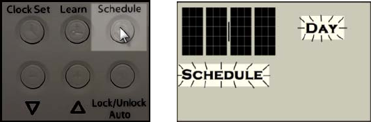
Establish a Schedule
The 24-hours of a day can be divided into two non-overlapping intervals, each with its
own start time and pet door setting (Auto/Locked/Unlocked). The Day and Night
segments on the LCD display are used to distinguish the intervals.
Press and hold the Schedule button for 2 seconds to enter the Schedule mode. The
Schedule segment on the LCD display will begin to blink and the Day interval is
automatically selected first. The Schedule button can be used to select between the
Day and Night intervals. The Down and Up buttons are used to change the start time (in
15 minute increments) of the selected interval and the Auto/Lock/Unlock button is used
to set the mode of the selected interval to one of the available pet door modes.
See ‘Switch between Locked, Unlocked and Automatic Modes’ for more details on the
door modes.
When Scheduling is turned on and an interval’s start time arrives, the pet door will make
the transition to the applicable pet door mode specified for that interval.
Turn Schedule On and Off
The Schedule button is used to turn on/off Schedule mode. Note the pet door may
transition to a different state when Schedule mode is turned on. For example, if the pet
door is locked at the point Schedule mode is turned on and the ‘Unlocked’ state is
associated with the current Schedule interval, the door will unlock.
Set Range
Five range settings are available. The Down and Up buttons are used to select the
desired range. Changing the range will decrease / increase the distance from the pet
door that a Computer Collar® is able to respond to the pet doors transmissions.
When either the Down or Up buttons are pressed, the current range setting is shown on
the display. This will be a number between 1 and 5. To the left of the range number will
be a vertical bar that indicates the strength of the signal being generated. Pressing the
Down or Up buttons again, while the range is being displayed, will decrease or increase
the range accordingly.
Switching between Locked, Unlocked and Automatic Modes
Pressing the Lock/Unlock/Auto button will cause the pet door to transition to one of the
three available modes:
‐ Auto
‐ Unlocked
‐ Locked.
If the Schedule mode is active when the Lock/Unlock/Auto button is pressed, the current
schedule interval’s pet door mode is overridden. The mode selected by the pressing of
the Lock/Unlock/Auto button takes precedence over the scheduled mode. When the
start time of the next schedule interval is reached, the original scheduled mode will be
reinstated. This allows scheduled pet door modes to be manually superseded on a
temporary basis until the next schedule interval begins.
When the pet door is placed in Auto mode, it is automatically locked and will only unlock
in the presence of an authorized and programmed Computer Collar® comes within
proximity of the pet door. The pet door will relocked automatically when all programmed
collars are out of range for 10 seconds.
When the pet door is set to Manual Locked or Manual Unlocked mode, the pet door will
lock or unlock, as appropriate, and remain in that mode state until the next schedule
interval occurs (if Schedule is on) or when the Lock/Unlock/Auto button is pressed.
When this mode is selected the proximity of an authorized Computer Collar® has no
effect on the pet door.
Each time the Lock/Unlock/Auto button is pressed, the display advances to the next
mode, but does not physically change the state of the pet door to that specific mode.
Only when the Learn button is pressed or after no button is pressed for 20 seconds
does the pet door set to the specific selected mode.
If the pet door fails to set to the selected mode there are 3 reasons why the pet door
may fail to establish the connection:
‐ High door motor current (motor turning is being hindered in some way)
‐ Pet door timeout (it took more than 18 seconds to transition to the specified
mode)
‐ Pet door jams (the door is unable to close, usually caused by an obstruction)
If the connection fails to occur, the LCD display will display the error and the pet door
mode will show the actual state of the door instead of the specified mode. For example,
if the Lock/Unlock/Auto is pressed to change the door from unlocked to locked, and a
jam occurs, the door will indicate that a jam has occurred and remain unlocked. NOTE:
When the door detects that the door is unable to travel freely while closing, it will re-
open and attempt to close again. A total of three attempts will be made to clear the
problem before a jam is deemed to have occurred and noted on the LCD display.
Changing Frequencies Between 7K and 10K
If Clock Set and Schedule buttons are pressed simultaneously and held for 2 seconds,
the frequency of the Magnetic Transmission mode will immediately change between 7
kHz and 10 kHz.
Disable and Enable the Pushbuttons
If the Down and Up buttons are pressed simultaneously and held for at least 2 seconds,
the keypad will become disabled. Repeating the process will enable the keypad and
return it to an active state.
A one second tone will sound indicating the change has occurred and a message will
scroll across the display when the pushbuttons have been disabled reading as, “Keypad
Locked”. If any of the keys are pressed while the keypad is locked, a “Keypad Locked”
message will scroll across the LCD display.
Low Battery Indication
The battery voltage is consistently measured once every 4 hours. If the reading is below
4.4 Volts each of the times it is checked within a 24-hour period, the Low Battery alarm
will activate. When this occurs, the pet door will beep and display “LOW BATT” on the
LCD display once every 20 seconds. The audible alarm can be disabled by pressing
any of the keypad buttons. If the audible alarm is disabled, the “LOW BATT” message
will appear on the LCD screen every 2 seconds.

Installing Your Invisible Fence® Brand Doorman™
Step 1
Determine Pet Door Location
1A 1B
1A Measure and mark your pet’s shoulder height on the door.
1B Determine location for the pet door. Draw a vertical center line through the shoulder
height line using a level.
NOTICE
If homeowner’s door or other application is not level, the pet door must be
marked level to swing properly.
Step 2
2A Remove door from hinges
2B Place on level saw horses and pad to protect the door
Helpful Tip: Clamp or weigh down the door to prevent it from moving.
NOTE: The pet door can be installed with the door hanging based on your skill level.
2C Match the marked lines on the door with the shoulder and center lines on the
template. Tape the template in place.
NOTICE
When applying the template there should be a minimum of 3” (7.6 cm) between
the bottom and sides of the door and the outer edge of the template to maintain
the structural integrity of the door.
Step 3
Cut Pet Door Opening
3A3B
3A Drill 1/2” holes in the inside corners of template. These will be the pilot holes for the
saw blade. Use a 3/8” drill bit to mark the mounting holes. Make sure that the drill is
level to endure the holes line up on interior and exterior of door. You will need to
enlarge the mounting holes on the interior side to ensure that the mounting post can be
inserted. Remove template from door.
Helpful Tip: Use both hands to hold drill steady and straight at a 90° angle.
3B Beginning in one of the pilot holes, cut along the template lines. You may need to
recut to square the opening. This is necessary for the pet door frame to fi t correctly.
Helpful Tip: Use a proper saw blade according to door material. Ensure that the
blades are sharp and straight. When cutting use both hands to hold the saw slow,
steady and straight at a 90° angle. This will prevent the blade from cutting
unevenly between interior and exterior areas of door.
NOTICE
Make sure there is nothing underneath the door where you will be drilling the
holes or cutting out opening.
Step 4
Install Pet Door
Before putting away the jigsaw, check fit by placing the interior frame (frame with the
control panel) inserting the mounting post into the mounting holes and putting frame
inside cutout. Repeat with the external frame. If frames do not fit inside the opening,
you may need to recut to square the opening before proceeding with installation.
4 Re-hang door and place interior frame on the door by inserting the mounting post in
the mounting holes. Make sure that the interior frame is flush with the door. Place
exterior frame by repeating interior frame steps. Make sure the mounting post on interior
and exterior frame align.
Step 5
Insert Screws
5 Thread mounting screws through interior frame and align with exterior frame. Tighten
with screwdriver. DO NOT OVERTIGHTEN. Helpful Tip: If using an electric screwdriver,
set on low torque.
Step 6
Train the Pet
6 Tape the flap open or remove the flap to help your pet become familiar with the pet
door opening. When your pet is more comfortable, let the flap down or reinstall and
operate the Invisible Fence® Brand Doorman™ in UNLOCKED Mode encouraging your
pet to push through the flap. Once your pet is comfortable entering and exiting through
the closed flap, set the pet door to AUTOMATIC Mode and operate with your pet’s
programmed Computer Collar® walking your pet up to the pet door until the Computer
Collar® is detected and the flap unlocks. Repeat training your pet to walk up to the
Invisible Fence® Brand Doorman™ and push open flap to the other side. Helpful Tip: Try
treats to encourage your pet to push through the pet door flap.
NOTE: The Invisible Fence® Brand Doorman™ is designed with an electric motor to
release and unlock the pet door flap when a SmartLink™ II code is present and
detected. Do not allow your pet to run or charge through the Invisible Fence® Brand
Doorman™.
Terms of Use and Limitation of Liability
1. Terms of Use
This Product is offered to you conditioned upon your acceptance without modification of
the
terms, conditions and notices contained herein. Usage of this Product implies
acceptance of all
such terms, conditions, and notices.
2. Proper Use
This Product is designed for use with pets where training is desired. The specific
temperament
of your pet may not work with this Product. If you are unsure whether this is appropriate
for
your pet, please consult your veterinarian or certified trainer. Proper use includes
reviewing
the entire Operating Guide provided with your Product and any specific Caution
statements.
3. No Unlawful or Prohibited Use
This Product is designed for use with pets only. This pet training device is not intended
to
harm, injure, or provoke. Using this Product in a way that is not intended could result in
violation of Federal, State or local laws.
4. Limitation of Liability
In no event shall Radio Systems® Corporation be liable for any direct, indirect, punitive,
incidental, special or consequential damages, or any damages whatsoever arising out
of or
connected with the use or misuse of this Product. Buyer assumes all risks and liability
from
the use of this Product.
5. Modification of Terms and Conditions
Radio Systems Corporation reserves the right to change the terms, conditions and
notices
under which this Product is offered.
Perchlorate Battery
Perchlorate Material – special handling may apply. See
www.dtsc.ca.gov/hazardouswaste/
perchlorate.
Important Recycling Advice
Please respect the Waste Electrical and Electronic Equipment regulations in your
country. This
equipment must be recycled. If you no longer require this equipment, do not place it in
the normal municipal waste system. Please return it to where it was purchased in order
that it can be placed in our recycling system. If this is not possible, please contact the
Customer Care
Center for further information.
Battery Disposal
Separate collection of spent batteries is required in many regions; check the regulations
in your area before discarding spent batteries.
Invisible Doorman™:
This device operates on four Alkaline batteries of the type C-cell with a 1.5 Volt, 8350
mAH capacity. Replace only with the equivalent batteries.
Computer Collar®:
This device operates on one Power Cap®. Replace only with Power Cap® from your
local Invisible Fence® Brand Dealer.
Compliance
US and Canada
Model: RAC00-13211
FCC ID: KE3-3001183
IC: 2721A-3001183
This device complies with Industry Canada license-exempt RSS standard(s). This
device complies with Part 15 of the FCC Rules. Operation is subject to the following two
conditions: (1) this device may not cause interference, and (2) this device must accept
any interference, including interference that may cause undesired operation of the
device.
Le présent appareil est conforme aux CNR d’Industrie Canada applicables aux
appareils radio exempts de licence. Cet appareil est conforme à la partie 15 des régles
FCC. L’exploitation est autorisée aux deux conditions suivantes : (1) l’appareil ne doit
pas produire de brouillage, et (2) l’utilisateur de l’appareil doit accepter tout brouillage
radioélectrique subi, même si le brouillage est susceptible d’en compromettre le
fonctionnement.
Modification or changes to this equipment not expressly approved by Radio Systems®
Corporation may void the user’s authority to operate the equipment.
This equipment has been tested and found to comply with the limits for a Class B digital
device, pursuant to part 15 of the FCC Rules. These limits are designed to provide
reasonable protection against harmful interference in a residential installation. This
equipment generates, uses, and can radiate radio frequency energy and, if not installed
and used in accordance with the instructions, may cause harmful interference to radio
communications. However, there is no guarantee that interference will not occur in a
specific installation. If interference does occur to radio or television reception, which can
be determined by turning the equipment off and on, the user is encouraged to try to
correct the interference by one or more of the following measures:
• Reorient or relocate the receiving antenna.
• Increase the separation between the equipment and the receiver.
• Connect the equipment to an outlet on a circuit different from that to which the receiver is
connected.
• Consult the dealer, or an experienced radio/TV technician for help.
This Class B digital apparatus complies with Canadian ICES-003.
Cet appareil numérique de la classe B est conforme à la norme NMB-003 du Canada.
Australia
This device complies with the applicable EMC requirements specified by the ACMA (Australian
Communications and Media Authority).
European Union
This equipment has been tested and found to comply with relevant EU Electromagnetic
Compatibility, Low Voltage and R&TTE Directives. Before using this equipment outside the EU
countries, check with the relevant local R&TTE authority. Unauthorized changes or
modifications to the equipment that are not approved by Radio Systems Corporation are in
violation of EU R&TTE regulations, could void the user’s authority to operate the equipment,
and void the warranty.
This product is in full compliance with the provisions of the R&TTE - Directive 1999/05/EEC.
The Declaration of Conformity can be found at:
http://www.invisiblefence.com/international/declarations-of-conformity.asp.