Radio Systems 3002789 MURS RF SNIFFER User Manual Mobile Commands and Display Messages
Radio Systems Corp MURS RF SNIFFER Mobile Commands and Display Messages
UserManual.wiki
>
Radio Systems
>
3002789 User Manual
User Manual
Navigation menu
Upload a User Manual
Namespaces
Wiki Guide
HTML
PDF
Info
Views
User Manual
Discussion / Help
Navigation
![Page 1 of 24 Radio Systems Corp. – Proprietary and Confidential GPS Containment: RF Sniffer/Status Unit PC Interface Manual v3 Initial File Date: 04/03/2012 Author: Scott McFarland Revision File Date: 09/10/2012 Related Documents: [1] US Patent - Maddox 6,903,682 B1 [2] GPSC System Manual v4 [3] GPSC Mobile Unit PC Interface Manual v4 [4] GPSC Base Unit PC Interface Manual v41 [4] 37287.00 DRAFT Revised Application (clean) (00259633).PDF "Actionable Position and Speed" Revision History: 04/03/2012 Version v1 Initial release. 09/10/2012 Version v2 SAM Converted TRACE200000 to a single line trace. Effects S23, S24, S25, S26, S27, S28, and S32. 09/10/2012 Version v3 Updated "Base Ping" with "Base GPS" and "Mobile Ping" with "Mobile GPS" per our current naming conventions. Changed from using the word "Packet" to describe an RF transmission to the word "Block".](https://usermanual.wiki/Radio-Systems/3002789/User-Guide-2093680-Page-1.png)
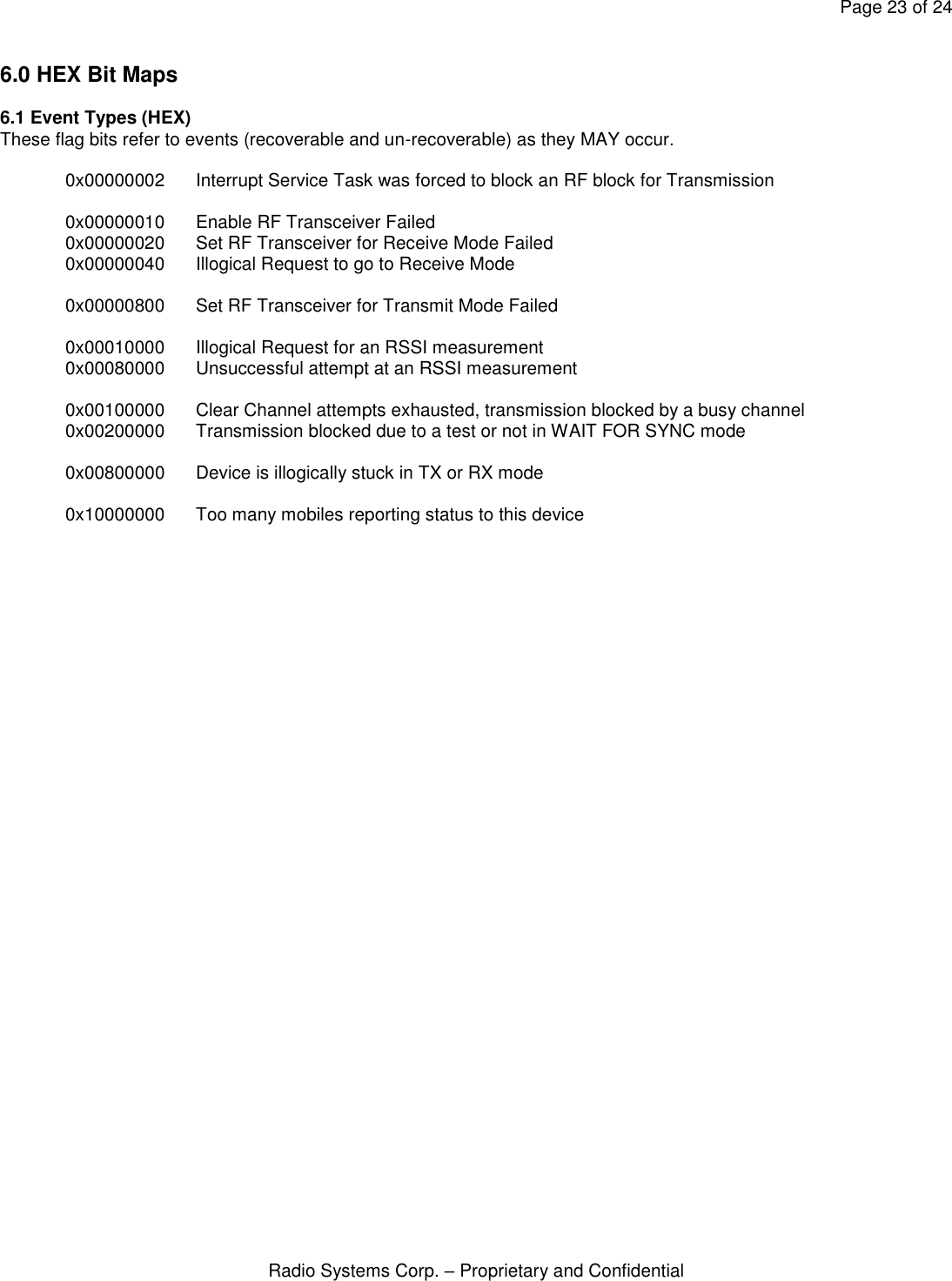
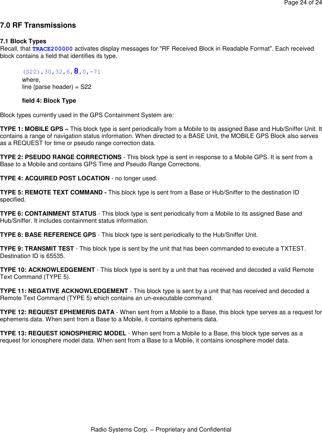
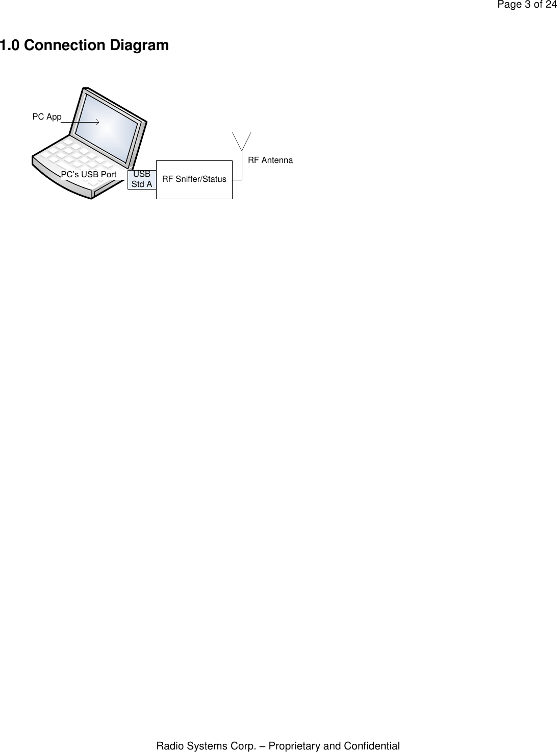
![Page 2 of 24 Radio Systems Corp. – Proprietary and Confidential Contents 1.0 Connection Diagram 2.0 Personal Computer Requirements 2.1 Hardware 2.2 Software 2.3 Port Settings 3.0 Input and Output Formats 3.1 Input Format 3.2 Output Format 4.0 Available Commands 4.1 Commands For All Likely Users 4.2 Commands Specific to Factory Test, Engineering, and/or Emissions Compliance 5.0 Decoding Output Headers and Messages 5.1 (Trace) Headers 5.2 [Task] Headers 6.0 Hex Bit Maps 6.1 Event Types (HEX): 7.0 RF Transmissions 7.1 Block Types](https://usermanual.wiki/Radio-Systems/3002789/User-Guide-2093680-Page-2.png)
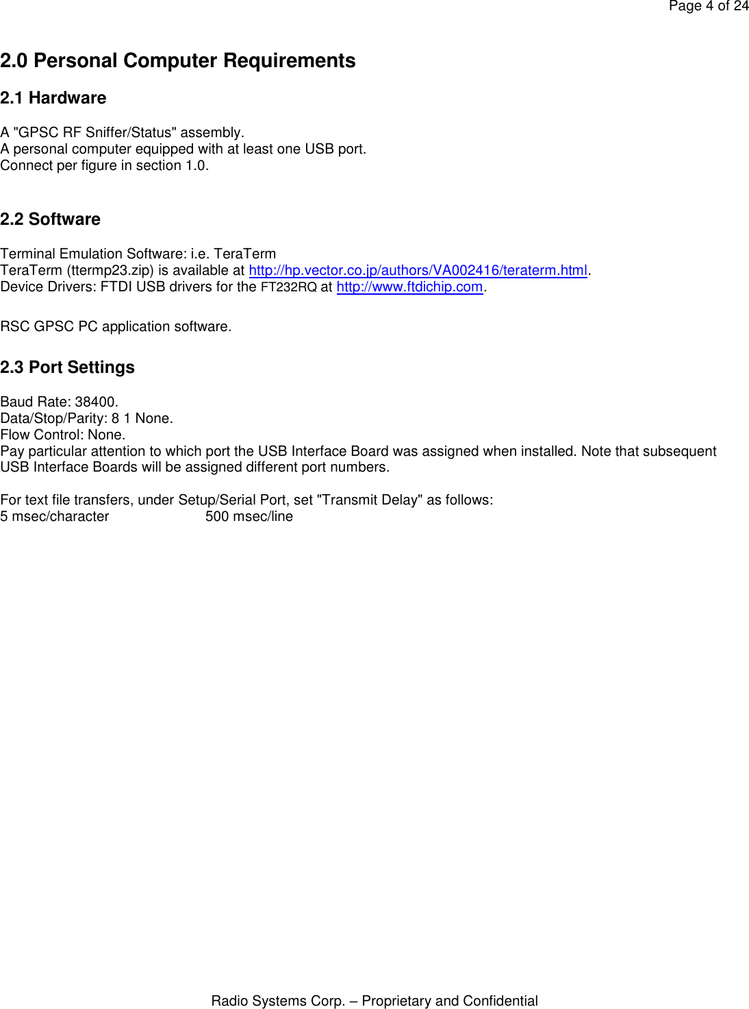
![Page 5 of 24 Radio Systems Corp. – Proprietary and Confidential 3.0 Input and Output Formats A Sniffer/Status Command Prompt will appear on the terminal emulator screen as, “SNIFF> “. Prior to entering or transferring command text, depress the <enter> key to force a Sniffer command prompt. If a command prompt does not appear, check all connections and PC port settings. 3.1 Input Format A Command is entered or transferred as text in CAPITAL LETTERS. The characters entered are echoed and appended to the end of the command prompt. A command is executed by depressing the <enter> key following the command text. For example, SNIFF> COMMAND<enter>. Some commands have a numeric input value which may accompany the command. For these commands, the input sequence is SNIFF> COMMANDxx..x<enter>, where xx..x is the numeric input value. The number of digits and range of the numeric value is command dependent. DO NOT put a SPACE between the command and the numeric input value. The numeric input value is always a WHOLE number, NO DECIMAL POINT. Items that typically require a decimal point (i.e. latitude and longitude) are entered in units that provide sufficient accuracy without a decimal point (i.e. 10e-06 degrees). If a text entry cannot be executed as typed, the SNIFFER will respond with either a [?] or it will display the command and setting as it is currently (i.e. did not accept the numeric input or one was not provided). 3.2 Output Format All responses from the unit will begin with one of two HEADERs. A (trace header) – precedes a display message activated by a command (i.e. the TRACExx..x command). A [task header] – precedes an informative message from a specific task. Informative [task] output may occur at any time. All fields following a header are comma delimited for easy parsing (i.e. capturing and decoding) by a computer. In general, the response to a command will be one or more lines starting with a (trace) or [task] header. See section, “Decoding Output Messages” for the meaning of each of the response fields. Example - After a POWER UP RESET As seen on the terminal emulator display: [SNV],POR [SNV],RESTORE-FFS [S],GPSC,Sniffer,V0.100,03-30-2012,(c)RSC SNIFF> Above is a multi-line output in response to a reset. [SNV] is a task header. The first line indicates a “power on reset” has occurred. The second line indicates that non-volatile parameters have been accessed and restored from the flash file system. [S] is also a task header. In this instance the SHELL task is displaying the firmware revision. Prior to entering or transferring command text, depress the <enter> key to force a Sniffer command prompt.](https://usermanual.wiki/Radio-Systems/3002789/User-Guide-2093680-Page-5.png)
![Page 6 of 24 Radio Systems Corp. – Proprietary and Confidential 4.0 Available Commands Commands are initiated by typing or transferring one of the following in ALL CAPITAL LETTERS and the <enter> key. Prior to entering or transferring command text, depress the <enter> key to clear any orphaned characters from the serial port buffers and force a command prompt. Commands for all likely users "VERSION" Display firmware version. "PRINTNV" Display parameter settings. "DEFAULTNV" Set parameters to their default settings. "DEVID" Display/Set Sniffer Unit Device ID. "BASEREFID" Display/Set Base Reference Unit Device ID. "CLEARMOBILESTATUS" Clear ALL mobile status information. "BOOT" Cause the unit to enter USB Boot mode. Commands Specific to Factory Test, Engineering, and/or Emissions Compliance "LEDTEST" Execute an LED TEST – Red/Grn. "TXTEST" Place RF transceiver into one of several transmit test modes (periodic or continuous). "TXTESTEND" Ends TXTEST, restores RF transceiver to normal operation. "RXTEST" Place RF transceiver into continuous receive mode. "RXTESTEND" Ends RXTEST, restores RF transceiver to normal operation. "DEST" Send a TEXT COMMAND to a remote device via the RF link. "TRACE" Selects one or more diagnostic messages, numeric value in HEX. "......" Provided on a need to know only basis for setting Manufacturing ID 1. "......" Provided on a need to know only basis for setting Manufacturing ID 2. 4.1 Commands For All Likely Users See section, “Decoding Output Headers and Messages” for the meaning of each of the response fields. VERSION<enter> Description: Display firmware version. Numeric Input Range: N/A Example (Inquiry): SNIFF> VERSION [S],GPSC,Sniffer,V0.100,03-30-2012,(c)RSC SNIFF> PRINTNV<enter> Description: Display parameter settings. Numeric Input Range: N/A Example (Inquiry): SNIFF> PRINTNV [SNV],DEVID,30 [SNV],BASEREFID,39 [SNV],MFG1,T [SNV],MFG2,A SNIFF> DEFAULTNV<enter>](https://usermanual.wiki/Radio-Systems/3002789/User-Guide-2093680-Page-6.png)
![Page 7 of 24 Radio Systems Corp. – Proprietary and Confidential Description: Display parameter settings. Numeric Input Range: N/A Example (Set): SNIFF> DEFAULTNV [S],DEFAULTNV [SNV],RESTORE-DEFAULTS SNIFF> Suggested Numbering Convention: It is REQUIRED to have a unique DEVID for each Base, Sniffer/Status, and Mobile unit within 2000 ft. of the installation. BASE ID’s should set for 10, 20, 30, 40, etc. Mobile DEVID’s associated with BASE ID 10 should be set to 11, 12, … 18 (8 max per Base) Sniffer/Status DEVID associated with BASE ID 10 should be set to 19 Mobile DEVID’s associated with BASE ID 20 should be set to 21, 22, … 28 (8 max per Base) Sniffer/Status DEVID associated with BASE ID 20 should be set to 29 etc. DEVIDxx..x<enter> Description: Display or set the Sniffer/Status Unit DEVICE ID. If a bad or no numeric input is supplied, the current DEVID is displayed. When a valid numeric input is supplied, non-volatile memory will be updated with the numeric value and displayed. The Sniffer/Status DEVICE ID (set with this command) must match the ID set with the "STATUSID" command on each Base and Mobile reporting to this device. Numeric Input Range: 1 - 65535. Example (Inquiry): SNIFF> DEVID [S],DEVID,19 SNIFF> Example (Set): SNIFF> DEVID29 [SNV],UPDATE [S],DEVID,29 SNIFF> BASEREFIDxx..x<enter> Description: Display or set the Base Reference Unit ID. A Sniffer/Status unit periodically communicates information with the Base Reference Unit. If a bad or no numeric input is supplied, the current BASEREFID is displayed. When a valid numeric input is supplied, non-volatile memory will be updated with the numeric value and displayed. Numeric Input Range: 1 - 65535. Example (Inquiry): SNIFF> BASEREFID [S],BASEREFID,10 SNIFF>](https://usermanual.wiki/Radio-Systems/3002789/User-Guide-2093680-Page-7.png)
![Page 8 of 24 Radio Systems Corp. – Proprietary and Confidential Example (Set): SNIFF> BASEREFID20 [SNV],UPDATE [S],BASEREFID,20 SNIFF> CLEARMOBILESTATUS<enter> Description: Clear ALL mobile status accumulated in RAM data structure. Numeric Input Range: N/A Example (Inquiry): BASE> CLEARMOBILESTATUS [S],CLEARMOBILESTATUS BASE> BOOT<enter> Description: Cause the unit to enter USB Boot mode. Numeric Input Range: N/A Example (Inquiry): SNIFF> BOOT 4.2 Commands Specific to Factory Test, Engineering, and/or Emissions Compliance Manufacturing ID commands are made available on an as needed basis only! The operator must end the current test before beginning a new test. LEDTEST<enter> Description: A red – green sequence will be executed. Numeric Input Range: N/A Example (Execute): SNIFF> LEDTEST [S],LEDTEST SNIFF> RXTEST<enter> Description: The RF transceiver is placed into continuous receive only mode. Numeric Input Range: N/A Example (Execute): SNIFF> RXTEST [S], RXTEST SNIFF> RXTESTEND<enter> Description: Ends "RXTEST", restores RF transceiver to normal operation. Numeric Input Range: N/A Example (Execute):](https://usermanual.wiki/Radio-Systems/3002789/User-Guide-2093680-Page-8.png)
![Page 9 of 24 Radio Systems Corp. – Proprietary and Confidential SNIFF> RXTESTEND [S], RXTESTEND SNIFF> TXTESTx<enter> Description: Places RF transceiver into one of several transmit test modes. Numeric Input Range: NONE, 1, 4, 5 Examples (Execute): SNIFF> TXTEST<enter> full data blocks are transmitted every 2 secs (periodic). SNIFF> TXTEST1<enter> produces a continuous carrier only signal. SNIFF> TXTEST4<enter> continuous 1010 modulated data signal. SNIFF> TXTEST5<enter> continuous PN9 modulated data signal (random data). Example (Execute a full data block periodic test): SNIFF> TXTEST [S],TXTEST,0 SNIFF> The following information will be displayed for a TXTEST command and will continue for 100 transmission blocks or until a TXTESTEND command is entered. [S],TXTEST,100 [S],TXTEST,99 [S],TXTEST,98 . . . [S],TXTEST,1 Example (Execute a continuous test): SNIFF> TXTEST1 [S],TXTEST,1 SNIFF> When performing tests 1, 4, or 5, the RF channel is 100% consumed and no longer available for other routine transmissions. Therefore, you will also see the following when performing one of these tests. The following text also serves as a reminder to execute a TXTESTEND command. [Event],!!WIP TXTESTEND<enter> Description: Ends "TXTEST", restores RF transceiver to normal operation. Numeric Input Range: N/A Example (Execute): SNIFF> TXTESTEND [S],TXTESTEND SNIFF>](https://usermanual.wiki/Radio-Systems/3002789/User-Guide-2093680-Page-9.png)
![Page 10 of 24 Radio Systems Corp. – Proprietary and Confidential DESTxxxxxcommandtext<enter> Description: Forward a text command over the RF channel to a specific unit. Since the RF transceiver in a Mobile Unit is predominantly off, commands for a Mobile Unit must be queued and await transmission until the destination Mobile is ready to receive. Numeric Input Range: Mobile ID (5 digits with leading 0’s) followed by Mobile command text and any numeric input. Example (Execute): SNIFF> DEST00032TONE [S],Command-in-Queue [S],TONE,32 SNIFF> [S],Command-Accepted,32 TRACEx<enter> Description: Selects one or more diagnostic output messages, numeric value in HEX. See section, “Decoding Output Headers and Messages” for the meaning of each of the response fields. Setting more than one bit location to a one will display each trace diagnostic message. It is STRONGLY RECOMMENDED that only one message is selected at a time. The command response includes a timer used to automatically shut all traces off after 300 seconds. Numeric Input Range: value 0 to FFFFFFFF (HEX), leading zeros are not required Example (Execute): SNIFF> TRACE200000 [S],TRACE,0x00200000,300 Example (to see how many seconds are left before auto-shutoff): SNIFF> TRACE [S],TRACE,0x00200000,187](https://usermanual.wiki/Radio-Systems/3002789/User-Guide-2093680-Page-10.png)
![Page 11 of 24 Radio Systems Corp. – Proprietary and Confidential 5.0 Decoding Output Headers and Messages Most status and diagnostic messages are turned “ON” and “OFF” by the TRACExx…x command. Trace activated messages are suitable for parsing by a computer program as part of a GUI. Each (trace) activated display line will begin with one of the (trace) HEADERs detailed below. A (trace)will automatically shut-off once the (trace) timer decrements to zero. When a (trace) is executed, the timer is set for 300 seconds. Individual FIRMWARE TASKS will also display messages deemed informative regardless of the TRACExx…x command. Their output can occur at any time and is also suitable for parsing by a computer program. Each [task] output line and will begin with one of the [task] HEADERs detailed below. Each header, (trace) or [task], can be uniquely identified (either individually or by using the secondary parse strings that accompany the header). Once identified, the defined comma delimited fields that follow may be decoded. The receive program must check for the correct number of fields associated with each HEADER and/or check each input character for the beginning of a NEW HEADER (either a "(" or a "["). The receive program may abort the decoding if the message is garbled due to multiple output messages. Example: !!WIP](https://usermanual.wiki/Radio-Systems/3002789/User-Guide-2093680-Page-11.png)
![Page 12 of 24 Radio Systems Corp. – Proprietary and Confidential 5.1 (Trace) Headers A (trace) diagnostic message is turned “ON” or “OFF” by the TRACExx…x command. The xx…x (HEX) numeric input value represents a 32 bit map. A message is activated by turning on the corresponding bit in the bit map and is de-activated by turning the bit off. A (trace) header is bracketed by “()”. To end any and all TRACE(s), type TRACE0. All (traces) will end if the (trace) timer decrements to zero. Below is a list of available (trace) activated messages. Hex Map: Message Description: Command: 0x00000010 RF Receive Block in BLOCK Format TRACE10 0x00000020 RF Receive Block in WORD Format TRACE20 0x00001000 RF Receive Block in BLOCK Format containing Bit Errors TRACE1000 0x00002000 RF Receive Block in WORD Format containing Parity Error TRACE2000 0x00004000 Mobile Status TRACE4000 0x00100000 Low level RF Channel activity TRACE100000 0x00200000 RF Received Block in Readable Format TRACE200000 0x00400000 RF Noise Floor Measurements TRACE400000 Multiple TRACES (i.e. messages) may be active simultaneously, however it is NOT RECOMMENDED. To end any and all TRACE(s), type TRACE0 at any time, regardless of the characters being displayed on the screen. The (S#) header, where # is a unique number, precedes a trace message that has been turned on by command. Each header identifies the proper way to interpret the comma delimited fields that follow. (S6) – Header for RF Receive Blocks in BLOCK Format, a continuous response activated by TRACE10 or Header for RF Receive Block in BLOCK Format containing Bit Errors, a continuous response activated by TRACE1000 SNIFF> TRACE10 or TRACE1000 [S],TRACE,0x00000010,300 (S6),0,0,-70 . . where, line (parse header) = S6 field 1: Block Codeword Errors field 2: Block Bit Errors field 3: Received Signal Strength Note, TRACE1000 will only display blocks with bit errors. (S7) – Body for RF Receive Blocks in BLOCK Format, a continuous response activated by TRACE10 or Body for RF Receive Block in BLOCK Format containing Bit Errors, a continuous response activated by TRACE1000 (S7),0x00203474 (S7),0x001E7567 (S7),0x012A011F (S7),0x2E20063B (S7),0x1404A4CF (S7),0x1388067C (S7),0x00000000 (S7),0x00000000](https://usermanual.wiki/Radio-Systems/3002789/User-Guide-2093680-Page-12.png)
![Page 13 of 24 Radio Systems Corp. – Proprietary and Confidential (S7),0x00410126 (S7),0x0039FE7A (S7),0xDF2B2E8C (S7),0x6000A297 (S7),0x00005EAE (S7),0x19209168 (S7),0x40064071 (S7),0x00C84D1A . . where, line (parse header) = S7 field 1: 32 bit Receive Data Word (HEX) Note, TRACE1000 will only display blocks with bit errors. (S8) – Header for RF Receive Block WORD Format, a continuous response activated by TRACE20 or Header for RF Receive Block WORD Format containing Parity Error, a continuous response activated by TRACE2000 SNIFF> TRACE20 or TRACE2000 [S],TRACE,0x00000020,300 (S8),32,30,6,0,1,4,0,0,5,-73 . . where, line (parse header) = S8 field 1: Source ID field 2: Destination ID field 3: Block Type field 4: Multi-Block transmission, 1 is yes, 0 is no field 5: Last Block of transmission, 1 is yes, 0 is no field 6: Transmit # field 7: Block Codeword Errors field 8: Block Bit Errors field 9: Block Ones Count field 10: Received Signal Strength Note, TRACE2000 will only display blocks with errors. (S9) – Body for RF Receive Block WORD Format, a continuous response activated by TRACE20 or Body for RF Receive Block WORD Format containing Parity Error, a continuous response activated by TRACE2000 (S9),0x012A (S9),0x0171 (S9),0x0008 (S9),0x0128 (S9),0x2710 (S9),0x0000 (S9),0x0000 (S9),0x0000 (S9),0x00F5 (S9),0x0006 (S9),0x06DF (S9),0x2C28 (S9),0x0004](https://usermanual.wiki/Radio-Systems/3002789/User-Guide-2093680-Page-13.png)
![Page 14 of 24 Radio Systems Corp. – Proprietary and Confidential (S9),0x0000 (S9),0x1632 (S9),0x6120 (S9),0x005A (S9),0x005B . . where, line (parse header) = S9 field 1: 16 bit Receive Data Word (HEX) Note, TRACE2000 will only display blocks with errors. (S16) – Mobile Status, a continuous response activated by TRACE4000. Information presented here is collected from received MOBILE GPS and CONTAINMENT STATUS blocks. The information collected is maintained in RAM memory. Information is collected for up to 8 Mobile's. SNIFF> TRACE4000 [S],TRACE,0x00004000,300 (S16),32,0.266,-119,-90,3829,1,3,7,35.914260,-84.134736,1,1,4,0.0,22.1,35.914271,-84.134734,5,0,0,0 . . where, line (parse header) = S16 field 1: Mobile ID field 2: Mobile Firmware Version Alias field 3: Mobile RF Noise Floor field 4: Mobile average receive level for Base RF transmissions field 5: Mobile Battery (mV) field 6: Mobile Navigation has Started, 1 is yes, 0 is no field 7: Mobile Fix Quality Metric (3=hi, 2=par, 1=lo, 0=no fix) field 8: Mobile most recent Time to First Useable Fix field 9: Mobile GNSS latitude (decimal degrees) field 10: Mobile GNSS longitude (decimal degrees) field 11: Mobile within Containment Area, 1 is yes, 0 is no field 12: Mobile is Armed for Corrections, 1 is yes, 0 is no field 13: Mobile Seconds without Motion field 14: Mobile Actionable Speed field 15: Mobile Distance to Nearest Boundary Segment field 16: Mobile Actionable latitude (decimal degrees) field 17: Mobile Actionable longitude (decimal degrees) field 18: Containment Correction Level Setting field 19: WARNING Event Count field 20: CORRECTION Event Count field 21: DISARM Event Count (S18) – RF Noise Floor Measurements, a continuous response activated by TRACE400000 SNIFF> TRACE400000 [S],TRACE,0x00400000,300 (S18),-116 (S18),-116 (S18),-120 (S18),-125 (S18),-123 . .](https://usermanual.wiki/Radio-Systems/3002789/User-Guide-2093680-Page-14.png)
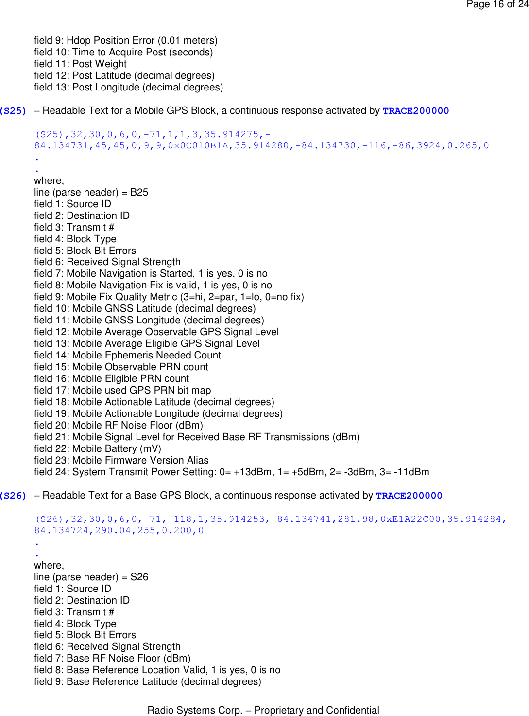
![Page 15 of 24 Radio Systems Corp. – Proprietary and Confidential where, line (parse header) = S18 field 1: RF Noise Floor (dBm) (S22) – Header for RF Received RF Blocks in Readable Format, a continuous response activated by TRACE200000. This header is the generic output for all other RF Blocks that are not otherwise printed in readable format for by S23, S24, S25, S26, S27, S28, or S32. SNIFF> TRACE200000 [S],TRACE,0x00200000,300 (S22),32,30,0,6,0,-71 where, line (parse header) = S22 field 1: Source ID field 2: Destination ID field 3: Transmit # field 4: Block Type field 5: Block Bit Errors field 6: Received Signal Strength (S23) – Readable Text for a Transmit Test Block, a continuous response activated by TRACE200000 (S23),32,30,0,6,0,-71,100 . . (S23),32,30,0,6,0,-71,99 where, line (parse header) = S23 field 1: Source ID field 2: Destination ID field 3: Transmit # field 4: Block Type field 5: Block Bit Errors field 6: Received Signal Strength field 7: Test Block # (S24) – Readable Text for a Mobile Post Block, a continuous response activated by TRACE200000 (S24),32,30,0,6,0,-71,1,-75,44,322,164,4,4,35.914286,-84.134748 . . where, line (parse header) = S24 field 1: Source ID field 2: Destination ID field 3: Transmit # field 4: Block Type field 5: Block Bit Errors field 6: Received Signal Strength field 7: Post # field 8: RF Received Signal Strength](https://usermanual.wiki/Radio-Systems/3002789/User-Guide-2093680-Page-15.png)
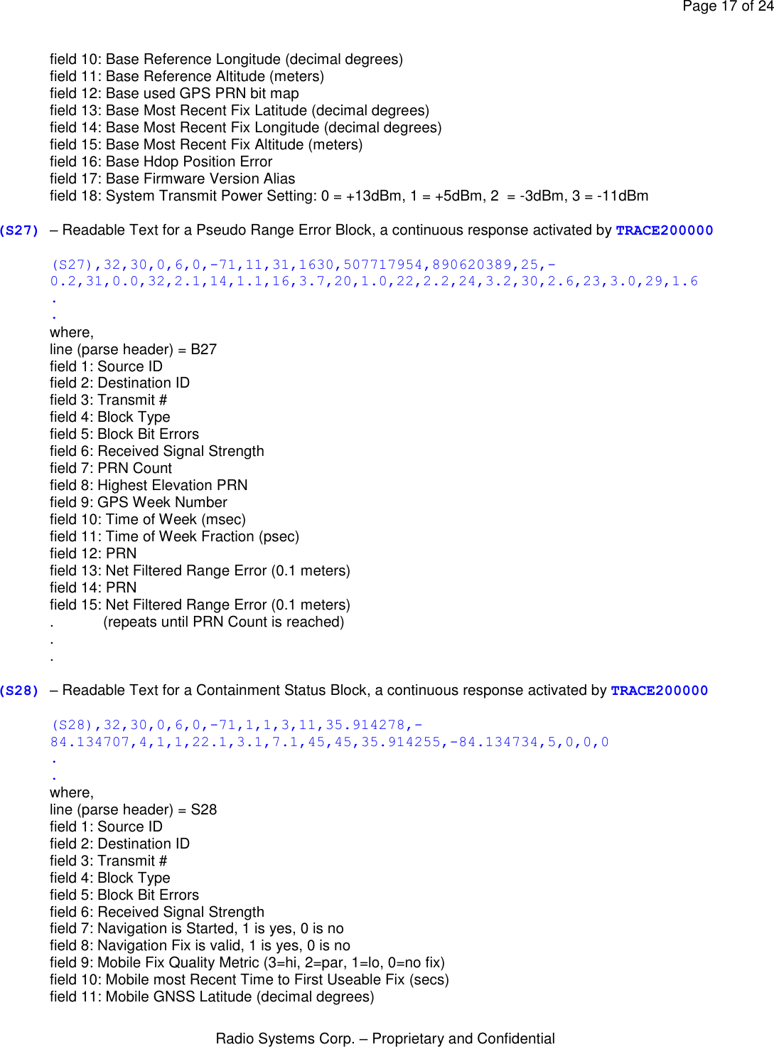
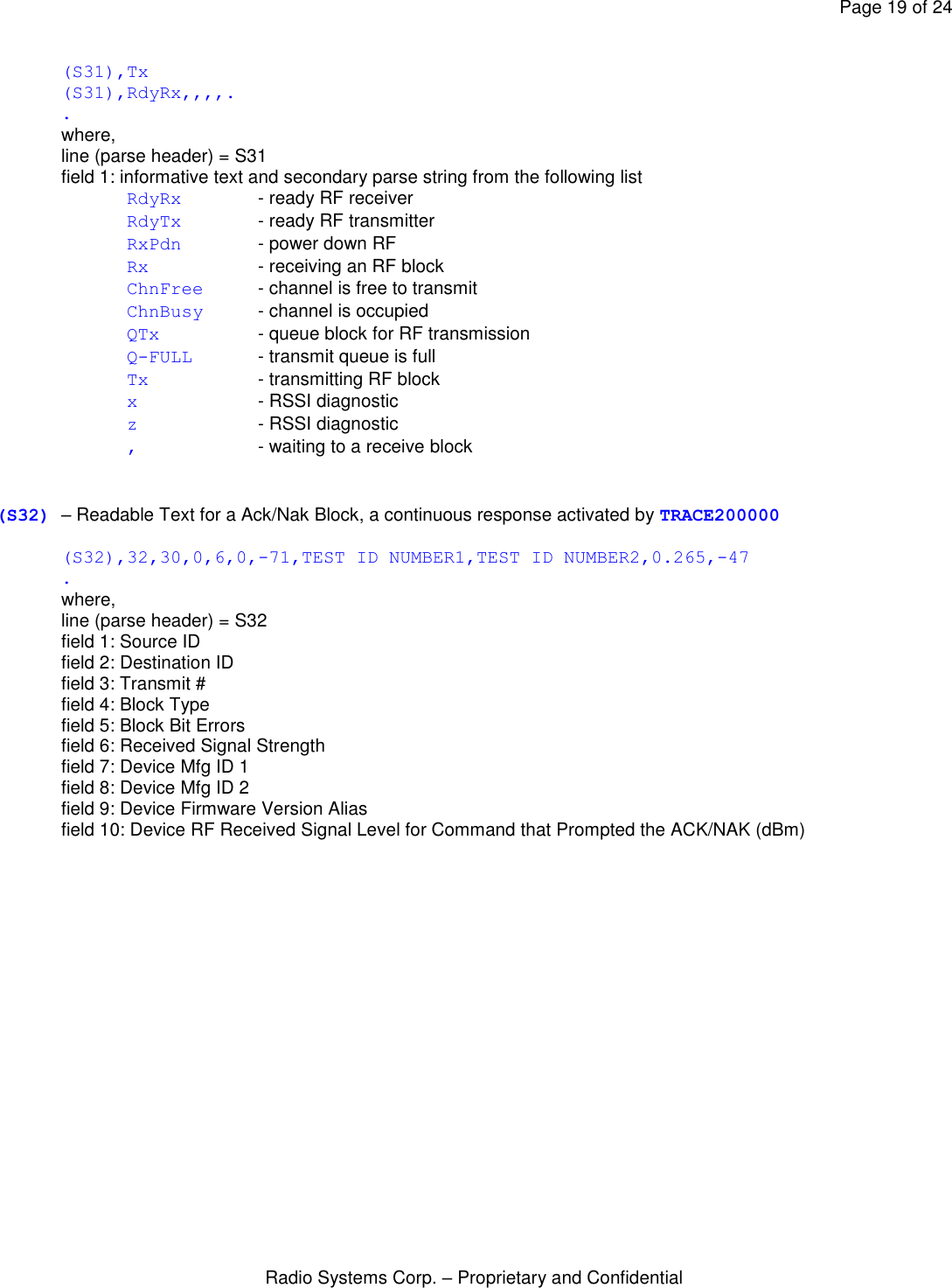
![Page 18 of 24 Radio Systems Corp. – Proprietary and Confidential field 12: Mobile GNSS Longitude (decimal degrees) field 13: Mobile Seconds without Motion field 14: Mobile is within the Containment Area, 1 is yes, 0 is no field 15: Mobile is Armed for Corrections, 1 is yes, 0 is no field 16: Mobile Distance to Nearest Boundary Segment (ft.) field 17: Mobile Actionable Speed (ft. / sec) field 18: Mobile Time to Nearest Boundary Segment (secs) – 1000 if the time is not relevant field 19: Mobile Average Observable GPS Signal Level field 20: Mobile Average Eligible GPS Signal Level field 21: Mobile Actionable Latitude (decimal degrees) field 22: Mobile Actionable Longitude (decimal degrees) field 23: Containment Correction Level Setting field 24: WARNING Event Count field 25: CORRECTION Event Count field 26: DISARM Event Count (S29) – not used (S30) – RF Receive Block in WORD Format containing Parity Error, a continuous response activated by TRACE2000 (S30),76 . . where, line (parse header) = S30 field 1: Ones Count Sum (Compare to field 9: Block Ones Count of the header line (B8)) (S31) – Low level RF channel activity, a continuous response activated by TRACE100000 !!WIP SNIFF> TRACE100000 [S],TRACE,,0x00100000,300 (S31),Rx (S31),Rx (S31),Rx,,,,, (S31),Rx (S31),Rx (S31),Rx (S31),QTx,,, (S31),ChnFree (S31),RdyTx (S31),Tx (S31),Tx (S31),Tx (S31),RdyRx,,,,,,,, (S31),Rx (S31),Rx,,,,,,, (S31),Rx (S31),Rx (S31),Rx (S31),QTx,,, (S31),ChnFree (S31),RdyTx (S31),Tx (S31),Tx](https://usermanual.wiki/Radio-Systems/3002789/User-Guide-2093680-Page-18.png)
![Page 20 of 24 Radio Systems Corp. – Proprietary and Confidential 5.2 [Task] Headers A [task header] is bracketed by “[]” and identifies the line as an informative task output message. All fields following the header are comma delimited. Specific task headers are: [T] Periodic Task Header [P] Protocol Task Header [PSwi] Protocol Software Interrupt Header [R] RF Comm Task Header [S] Shell Task Header [Event] Diagnostic Event Activity Header [SNV] Sniffer Non-Volatile File Activity Header 5.2.3 [S] task header. Additional informative text and output fields that accompany the [S] task header. [S],“Command Text” (See also “Available Commands” section). [S],GPSC,Sniffer,V0.100,03-30-2012,(c)RSC [S],Command-in-Queue [S],Command-Accepted [S],Command-Failed [S],Pls End Current Test First Example (“Command Text” Inquiry): SNIFF> DEVID [S],DEVID,19 SNIFF> line 1: [task header] = S field 1: DEVID, informative text displaying the command to be executed field 2: numeric value for DEVID Example (“Command Text” Set): SNIFF> DEVID20 [SNV],UPDATE [S],DEVID,20 SNIFF> line 1: (parse header) = NV field 1: UPDATE, informative text, secondary parse string line 2: [task header] = S field 1: DEVID, informative text displaying the command to be executed field 2: numeric value for DEVID Example (“DEST” Command): SNIFF> DEST00032TONE [S],Command-in-Queue [S],TONE,32 SNIFF>](https://usermanual.wiki/Radio-Systems/3002789/User-Guide-2093680-Page-20.png)
![Page 21 of 24 Radio Systems Corp. – Proprietary and Confidential [S],Command-Accepted,32 line 1: [task header] = S field 1: Command-in-Queue informative text indicating the command is in queue and awaiting transmission line 2: [task header] = S field 1: TONE informative text displaying the command is being forwarded to a device field 2: DEVID of the Unit to receive the command (Note: this action mimics a typed command, therefore the Base prompt is also displayed.) line 3: [task header] = S field 1: Command-Accepted informative text indicating the command has been accepted by the device field 2: DEVID of the unit accepting the command Example (“VERSION” Command): SNIFF> VERSION [S],GPSC,Sniffer,V0.74,04-14-2011,(c)RSC where, line 1: [task header] = S field 1: GPSC informative text and secondary parse string field 2: Base informative text and secondary parse string field 3: Version number field 4: Version date field 5: RSC copywrite 5.2.4 [SNV] task header. Additional informative text and output fields that accompany the [SNV] task header. The [SNV] header signifies an operation involving non-volatile parameter activity. Non-volatile parameters are copied to RAM for real time access. When a parameter is accessed for display, it is accessed from RAM and a message of type [SNV],informative-text,value will appear. When a parameter is changed, it is first changed in RAM and then a new file is written to the non-volatile FLASH FILE SYSTEM. Whenever a change is made to the non-volatile FLASH FILE SYSTEM, the [SNV],UPDATE message will be displayed. !!WIP Instances of the [SNV]HEADER will appear as follows: [SNV],UPDATE - a update to non-volatile FLASH FILE SYSTEM [SNV],POR - a power on reset [SNV],RESTORE - a non-volatile file restore operation [SNV],RESTORE-DEFAULTS - a non-volatile file restore and set to default operation where, line (parse header) = SNV field 1: informative text and secondary parse string The [SNV] header is also used when accessing and displaying non-volatile memory parameters in response to various commands, (i.e. PRINTNV). When accessing and displaying non-volatile memory parameters one or more of the following will appear: [SNV],DEVID,39 where, line (parse header) = SNV](https://usermanual.wiki/Radio-Systems/3002789/User-Guide-2093680-Page-21.png)
![Page 22 of 24 Radio Systems Corp. – Proprietary and Confidential field 1: DEVID, informative text and secondary parse string [SNV],BASEREFID,30 where, line (parse header) = SNV field 1: BASEREFID, informative text and secondary parse string field 2: BASEREFID, the destination ID that this unit will use to report status information 5.2.5 [Event] task header. Additional informative text and output fields that accompany the [Event] task header. The [Event] task header precedes an event diagnostic message. This message type may appear at any time. Example: [Event],!!WIP where, line (parse header) = Event field 1: Task ID Number field 2: Event ID Number field 3: Event Debug Value](https://usermanual.wiki/Radio-Systems/3002789/User-Guide-2093680-Page-22.png)