Radio Systems 300741 TRANSMITTER FOR PET BOUNDARY SYSTEM User Manual
Radio Systems Corp TRANSMITTER FOR PET BOUNDARY SYSTEM Users Manual
Users Manual
paw point
custom wireless fence
operating and training guide
Model Number
PIF00-13651
PLEASE READ THIS ENTIRE GUIDE BEFORE BEGINNING
2 1-800-732-2677
Important Safety Information
Explanation of Attention Words and Symbols used in this guide
This is the safety alert symbol. It is used to alert you to potential personal injury hazards. Obey all safety messages that
follow this symbol to avoid possible injury or death.
WARNING indicates a hazardous situation which, if not avoided, could result in death or serious injury.
CAUTION, used without the safety alert symbol, indicates a hazardous situation which, if not avoided, could
result in harm to your pet.
NOTICE is used to address safe use practices not related to personal injury.
• Not for use with aggressive dogs. Do not use this product if your dog is prone to aggressive behavior.
Aggressive dogs can cause severe injury or death to their owners and others. If you are not sure that this
product is right for your dog, please talk to your veterinarian or a certified trainer.
• Risk of electric shock. Use the Fence Transmitter indoors in dry location only.
• Turn off power before changing Mode Selection Switch setting on Transmitter.
• This PetSafe® Paw Point Custom Wireless Fence is NOT a solid barrier. The system is designed to act as
a deterrent to remind pets by Static Correction to remain in the boundary established. It is important that
you reinforce training with your pet on a regular basis. Since the tolerance level to Static Correction varies
from pet to pet, Radio Systems® Corporation CANNOT guarantee that the system will, in all cases, keep a
pet within the established boundary. Not all pets can be trained to avoid crossing the boundary! Therefore,
if you have reason to believe that your pet may pose a danger to others or harm himself if he is not kept
from crossing the boundaries, you should NOT rely solely upon the PetSafe® Paw Point Custom Wireless
Fence to confine your pet. Radio Systems® Corporation shall NOT be liable for any property damage,
economic loss or any consequential damages, sustained as a result of any animal crossing the boundary.
• Proper fit of the collar is important. A collar worn for too long or made too tight on the pet’s neck may
cause skin damage. Ranging from redness to pressure ulcers; this condition is commonly known as bed
sores.
- Avoid leaving the collar on the dog for more than 12 hours per day.
- When possible reposition the collar on the pet’s neck every 1 to 2 hours.
- Check the fit to prevent excessive pressure; follow the instructions in this manual.
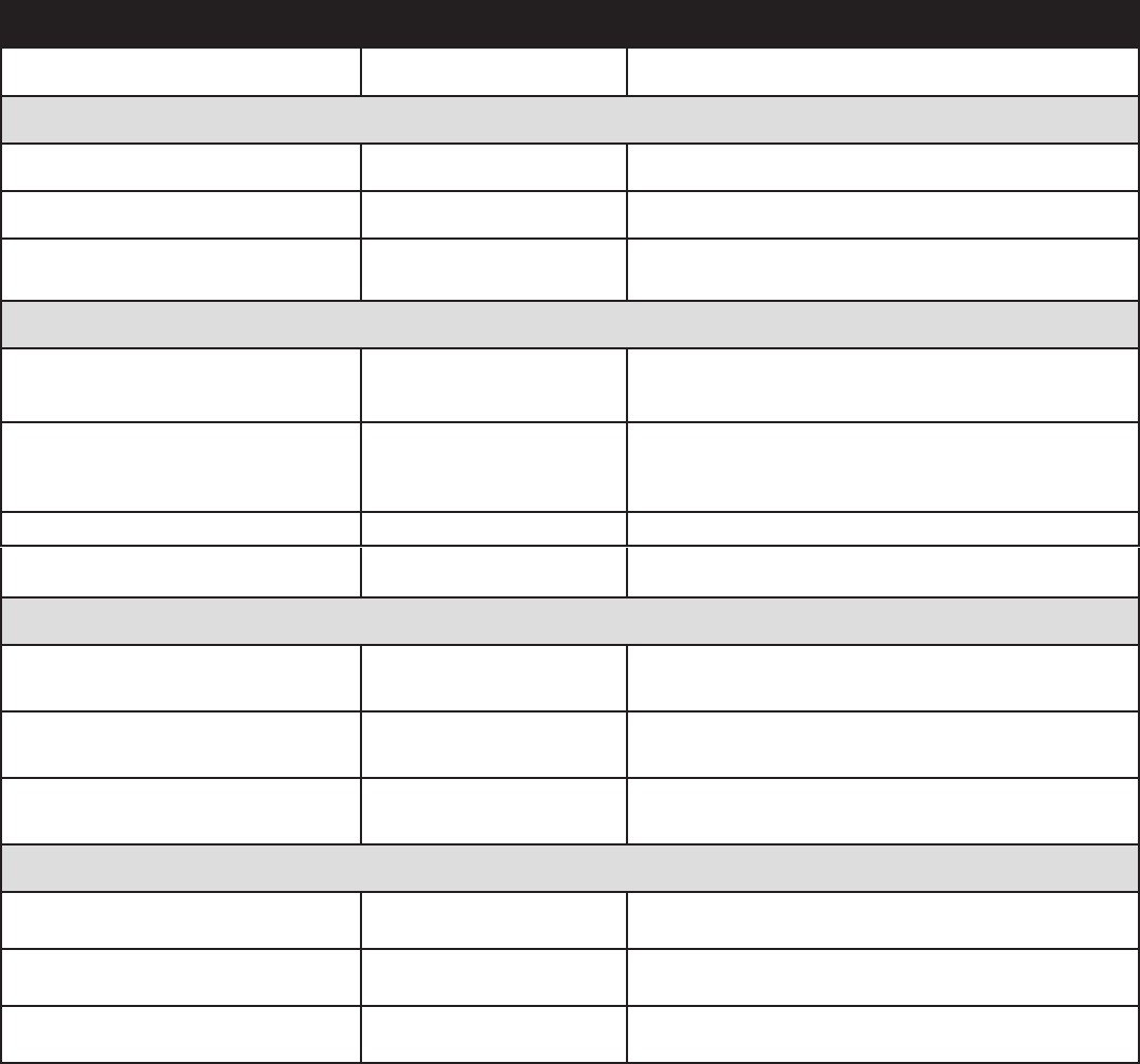
- Never connect a lead to the electronic collar; it will cause excessive pressure on the contacts.
- When using a separate collar for a lead, don’t put pressure on the electronic collar.
- Wash the dog’s neck area and the contacts of the collar weekly with a damp cloth.
- Examine the contact area daily for signs of a rash or a sore.
- If a rash or sore is found, discontinue use of the collar until the skin has healed.
- If the condition persists beyond 48 hours, see your veterinarian.
- For additional information on bed sores and pressure necrosis, please visit our website.

www.petsafe.net 3
Always remove the Receiver Collar from your pet when indoors to avoid accidental activation of the
Receiver Collar.
These steps will help keep your pet safe and comfortable. Millions of pets are comfortable while they wear
stainless steel contacts. Some pets are sensitive to contact pressure. You may find after some time that
your pet is very tolerant of the collar. If so, you may relax some of these precautions. It is important to
continue daily checks of the contact area. If redness or sores are found, discontinue use until the skin has
fully healed.
• You may need to trim the hair in the area of the Contact Points. Never shave the dog’s neck; this may lead
to a rash or infection.
• Always remove your dog’s Receiver Collar before performing any Transmitter testing.
• The Receiver Collar should not be on your dog when the system is tested. Your pet may receive an
unintended correction.
• The Boundary Width of the system must be tested whenever an adjustment is made to the containment
field to prevent unintended corrections to your pet.
• If you use a collar and leash for training, be sure the extra collar does not put pressure on the contact
points.
• Never remove power from the system when the collar is on the pet. This may activate the Receiver Collar.
• Radio Systems® Corporation recommends the use of an Uninterruptible Power Supply (UPS) for use with
your wireless fence. Should the power go out at your home, your pet will be unprotected. Power outages
can be unpredictable, and the use of a UPS will provide you with some time to properly restrain your pet.
• To prevent an unintended correction, after the Boundary Flags have been placed, be sure to set the static
correction on the Receiver Collar back to level 1 tone only.
• Do not charge your Receiver Collar every night. Charging too often can reduce battery life. Charge your
Receiver Collar when the Receiver Indicator Light blinks red/green; or when the light blinks red.
• Do not place anything on the top of the Transmitter or cover any ventilation holes. This may overheat the
Transmitter and cause early transmit failure.
• Do not place Transmitter in a closet or any other confined, unventilated area.

4 1-800-732-2677
Thank you for choosing PetSafe® brand. You and your pet deserve a companionship that includes
memorable moments and a shared understanding together. Our products and training tools
promote a lifestyle of protection, teaching, and love — essentials that influence memories for a
lifetime. If you have any questions about our products or training your pet, please visit our website
at www.petsafe.net or contact our Customer Care Center at 1-800-732-2677.
To get the most protection out of your warranty, please register your product within 30 days
at www.petsafe.net. By registering and keeping your receipt, you will enjoy the product’s full
warranty and should you ever need to call the Customer Care Center, we will be able to help
you faster. Most importantly, PetSafe® will never give or sell your valuable information to anyone.
Complete warranty information is available online at www.petsafe.net.
Table of Contents
Components ....................................................................................................................................................................................... 5
Other Items You May Need ............................................................................................................................................................... 5
How the System Works ...................................................................................................................................................................... 6
Key Definitions ................................................................................................................................................................................... 6
Operating Guide .......................................................................................................................................... 7
Lay out the System .......................................................................................................................................................................... 8
Set Up the Transmitter .................................................................................................................................................................. 11
Charge the Receiver Collar ........................................................................................................................................................... 11
Prepare the Boundary Programming Unit .................................................................................................................................... 12
Prepare the Receiver Collar for Programming .............................................................................................................................. 12
Place the Boundary Flags.............................................................................................................................................................. 13
Programming the Boundary .......................................................................................................................................................... 13
Test the Receiver Collar ................................................................................................................................................................ 14
Prepare the Receiver Collar .......................................................................................................................................................... 15
Fit the Receiver Collar ................................................................................................................................................................... 18
Training Guide ............................................................................................................................................ 20
Be Patient With Your Pet............................................................................................................................................................... 20
Day 1 - Boundary Awareness ........................................................................................................................................................ 21
Days 2 thru 4 - Continue Boundary Awareness ............................................................................................................................ 22
Days 5 thru 8 - Distraction Phase .................................................................................................................................................. 22
Days 9 thru 14 - Unleashed Supervision ....................................................................................................................................... 23
Days 15 thru 30 - Pet Monitoring ................................................................................................................................................. 23
Taking Your Pet Out of the Pet Area ................................................................................................................................................ 23
Accessories ....................................................................................................................................................................................... 24
Frequently Asked Questions ............................................................................................................... 24
Troubleshooting ......................................................................................................................................... 25
Terms of Use and Limitation of Liability .......................................................................................................................................... 27
Compliance ...................................................................................................................................................................................... 27
Customer Care International ............................................................................................................................................................ 27
www.petsafe.net 5
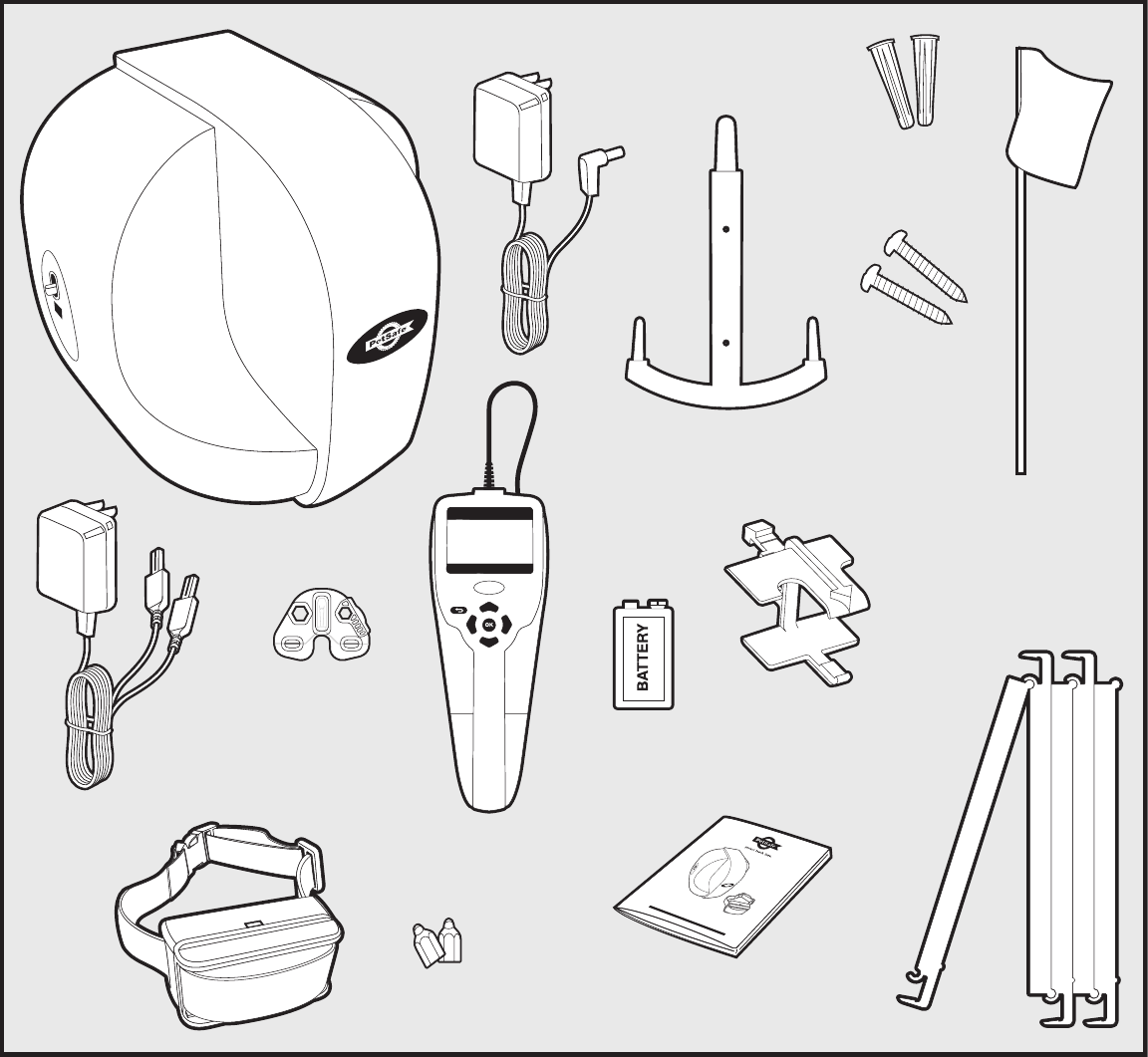
Components
Transmitter
Transmitter
Mounting Bracket
Receiver
Mounting
Bracket
Receiver
Handle
Boundary
Programming Unit
Operating and
Training Guide
Receiver
Collar
with
Short
Contact
Points
Test Light
Tool
Receiver
Charger
(6 ft.)
Long Contact
Points (2)
Boundary Flags (130)
Transmitter
Power
Adapter
(12 ft.)
boundary mapping
wireless fence
operating and training guide
Model Number
PIF00-13651
PLEASE READ THIS ENTIRE GUIDE BEFORE BEGINNING
9-Volt Alkaline
Battery
Mounting
Anchors (2)
Mounting
Screws (2)
Other Items You May Need
•Phillips screwdriver
•Scissors
•Lighter
•Drill
•Tape Measure
•Non-metallic collar and leash
Set up and training help: www.petsafe.net/fence

6 1-800-732-2677
How the System Works
The Transmitter is centrally located and transmits a radio signal 90 feet in all directions. Boundary flags are temporarily
positioned around your yard to define the Pet Area and guide you in the programming of the boundary. The Boundary
Programing Unit is used to collect boundary data information at each of the flag locations and then program this
boundary information into the Receiver Collar. The flags are also used for a visual aid in training your pet and are
removed when training is complete. Your pet wears the Receiver Collar that monitors your pet’s location within the
boundaries that you have set. As your dog approaches the boundary, the receiver issues a warning tone. If he proceeds
further he receives a safe but startling Static Correction. While harmless, the correction will persuade him to stay in the
containment area you’ve established. Once trained, your pet is allowed to roam freely in the Pet Area. The PetSafe®
Paw Point Custom Wireless Fence has been proven safe, comfortable, and effective for pets over 15 pounds.
Key Definitions
Transmitter: Transmits the radio signal. The positioning of the Transmitter is critical to the performance of this
system.
Pet Area: Distance from the Transmitter where your pet can roam freely.
Warning Zone: Outer edge of the Pet Area where your pet’s Receiver Collar begins to tone warning him not to go
into the Static Correction Area.
Boundary: Outlines area of containment. If dog exceeds Boundary, he will receive a Static Correction.
Static Correction Area: Area beyond the Programmed Boundary Flag Location where your pet’s Receiver Collar
will emit a Static Correction, signaling him to return to the Pet Area.
Receiver Collar: Receives the radio signal from the Transmitter
Receiver Indicator Light: Indicates the level of correction at which the Receiver Collar is set. This light also
indicates battery status.
Contact Points: Deliver the safe Static Correction when your pet moves into the Static Correction Area.
Mode Button: Turns Receiver Collar on/off and adjusts Static Correction Level.
Receiver Charger: Charges the battery inside the Receiver Collar.
Receiver Charge Jack: Connection point for charging Receiver battery.
Power Light: Indicates the Transmitter is turned on.
Power Jack: Where the Power Adapter plugs into the Transmitter. The Transmitter is powered by a standard AC
power outlet.
Transmitter Frequency Switch: Used to avoid interference with identical containment systems on neighboring
properties.
Boundary Programming Unit (BPU): Devise that connects to the Receiver Collar and configures Receiver Collar.
Boundary Flag: Flag that represents the location from which each boundary point will be programmed.
Reference Point: A specific point in your yard that can easily be remembered such as the corner of a sidewalk or
driveway. This is used during programming and for adding additional Receiver Collars.
www.petsafe.net 7
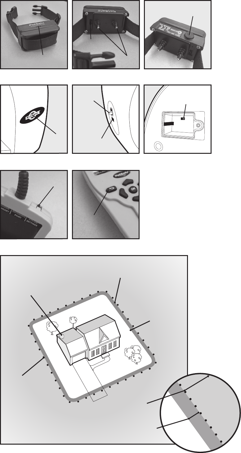
Receiver Collar
Receiver
Indicator Light Contact
Points
Receiver
Charge Jack
Transmitter
Boundary Programming Unit (BPU)
Power
Light
Power
Switch
BA
Power
Jack
Back
Button
Frequency
Switch
Mode
Button
Power
Switch
Boundary Callouts
Pet
Area
Static
Correction
Area
Fence
Transmitter
Warning
Zone
Boundary
Flags
Static
Correction
Area
Warning
Zone
Static
Correction
Area
8 1-800-732-2677
Operating Guide
Lay out the System
Basic Planning Tips
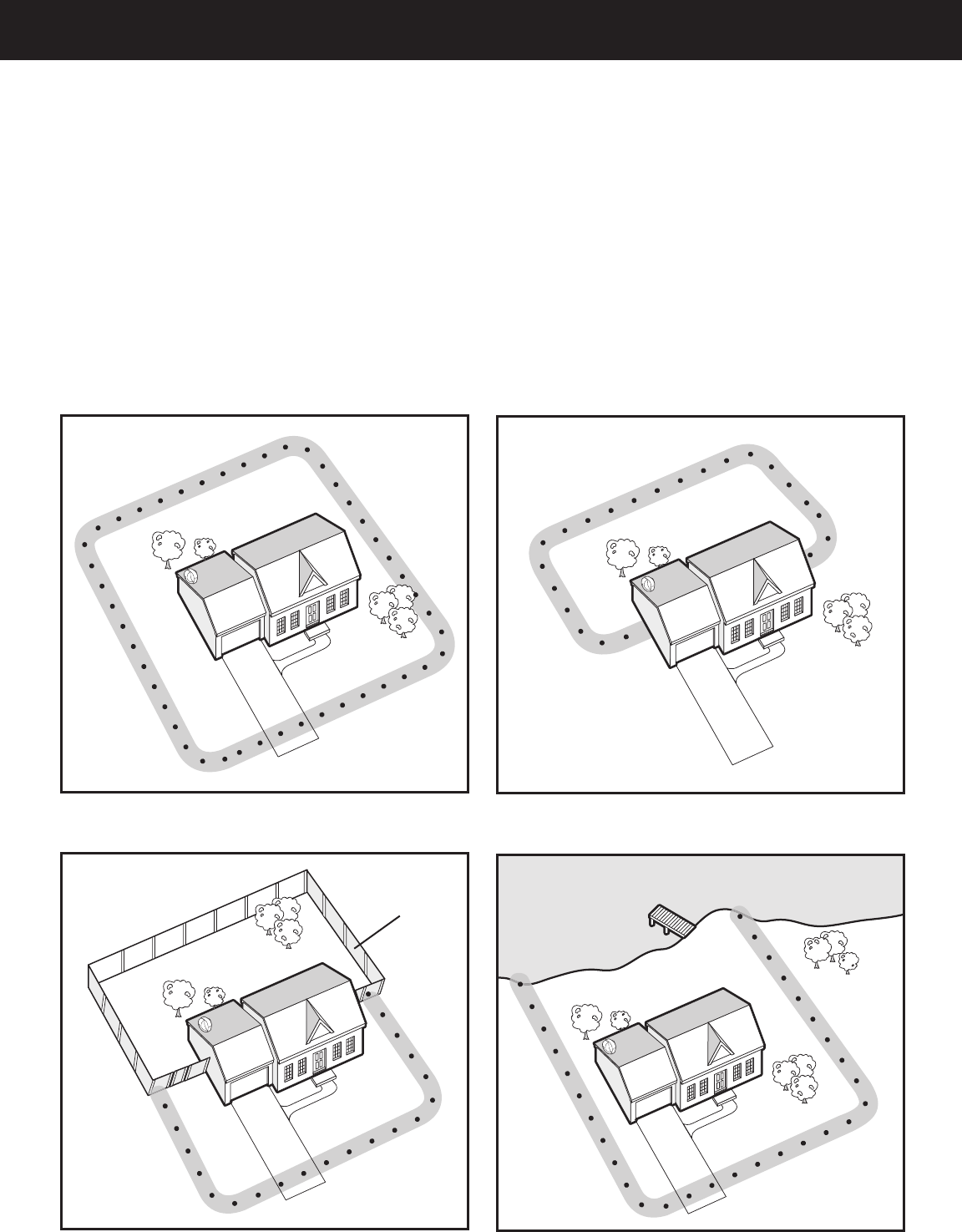
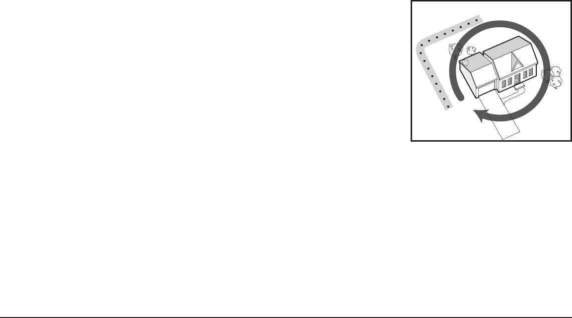
Design a layout that is suitable for your yard. Sample layouts are provided in this section. Decide if you want
a partial boundary or full boundary. A full boundary completely encircles the house and Fence Transmitter
located within the house (1A).
A partial boundary does not completely encircle the Transmitter. Partial boundaries typically have starting
and ending flags located at house corners or up against an outside wall or fence (1B, 1C, 1D). A partial
boundary may be appropriate if:
• You want to limit the containment area to a smaller portion of the yard, such as the back yard or front yard.
• You need to avoid running your boundary parallel with buried utilities.
• Your house is so large that it cannot be completely encircled with a full boundary covering the 90 foot maximum
range.
• You need to avoid violating any of the installation requirements on page 9.
Full boundary
1A
Partial boundary: Backyard only
1B
Partial boundary: Front yard only, using
fence as boundary
1C
Partial boundary: Majority of yard, using
lake as boundary
1D
Tip: Have all underground utilities marked before you decide which layout to pursue. In most areas this is a free service.
Step
1
Physical
Fence Lake
www.petsafe.net 9
In addition to knowing what type of layout you would like to have, you also need to meet several installation
requirements that must be followed in order for this system to function properly. Before setting up the
Transmitter, please review and follow these requirements.
Installation requirements
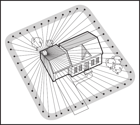
1. Each boundary flag placement must be located
between 15 feet and 90 feet from the transmitter.
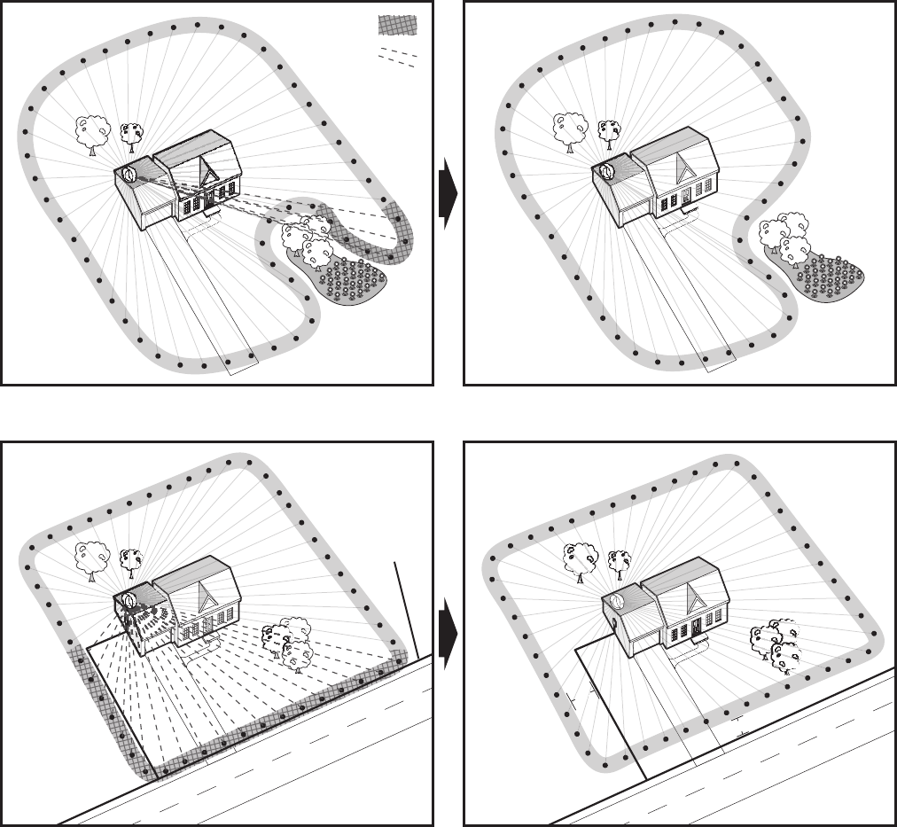
2. Each boundary flag must have a unique radial line to
the transmitter and cannot cross over another flag
radial line (1E, 1G, 1I).
3. When implementing a partial boundary, the first and
last boundary flags must be located within 1 foot of
the physical boundary, for example the house, fence,
outside wall, etc.
4. Any buried utility line such as power, CATV, phone
or metal water line must not run parallel (1H) with
the boundary unless separated from the boundary
by at least 15 feet (1I). Because they are not buried
as deeply, CATV or phone lines usually cause more
problems than power and water lines. This may require
using a partial boundary to avoid this problem.
5. Always avoid crossing buried lines at points far away
from the Transmitter. If it is required for the boundary
to cross a buried utility line, it should cross at
1E
Each
Boundary
Flag must
have a
unique
radial line
as shown.
approximately a right angle, and it is preferable that the crossing be as close to the Transmitter as possible,
but not closer than the 15 foot minimum (1H).
6. Do not mount the transmitter within 15 feet of large metal surfaces such as refrigerators, washer/dryers,
metal tables or shelving, water heaters, mirrors, furnaces, etc.
7. Do not mount the Transmitter within 2 feet of a concrete floor or adjacent to metal HVAC ductwork.
8. If placing the Transmitter in the garage, mount Transmitter near the ceiling and at least 2 feet above roof of
any vehicle parked in the area. Keep the Transmitter at least 10 feet from metal overhead garage doors.
9. Do not mount the Transmitter near electrical service panel or near main wiring trunks due to the large
concentration of house wiring.
10. Transmitters may be located in basements as long as requirement 5, 6 and 8 are observed.
11. For a partial boundary, locate Transmitter at least 10 foot away from entry door where dog will exit home
and enter containment area.
12. If a successful boundary is not obtained with the first choice transmitter location, try a second or third
location. Different locations can be tried by temporarily placing transmitter atop a stack of cardboard
boxes. If a trial location proves to provide a successful boundary, then transmitter can be more permanently
secured prior to programming a more exact final boundary.
If there is a pre-existing In-Ground containment system, the perimeter wire MUST be totally disconnected
from its Fence Transmitter.
www.earth.google.com is an effective tool to use to help you plan your layout.
10 1-800-732-2677
Non-unique
radial line =
Error =
Incorrect
1F
Multiple
Boundary
Flags are
blocking
unique radial
line to the
Transmitter.
Solution
1G Move Boundary Flags
to allow each Point
a unique radial
line to the
Transmitter.
Incorrect
1H
Boundary
Flags are
too close to
buried utility
lines.
Buried
Utility
Lines
15’
15’
5
1
Solution
1I Seperate
boundary at
least 15 feet
from buried
utlility lines.
Transmitter
should be
located as
close as
possible to
utility line and
Boundary
crossing.
www.petsafe.net 11
Installing the Transmitter
Before mounting the transmitter, make sure that you follow
Installation Requirements 5 through 9 on page 8. If the transmitter
will be mounted in a high traffic area, mount it high enough on
the wall so that you can walk underneath it. The Transmitter Power
Adapter is equipped with a 12 foot power cord to facilitate mounting
the transmitter high on the wall. It is important that the transmitter
is not moved once your boundary has been established.
To ensure proper operation, this transmitter must be permanently
mounted on a vertical, non-metallic surface using the mounting
bracket provided.
Remove mounting bracket from Transmitter. Using the screws and
mounting anchors provided, mount the bracket to the wall. Slide the
Transmitter over the bracket.
Plug the adapter into a functional AC wall outlet.
Slide the power switch to turn on the Transmitter.
THIS
SIDE UP
THIS
SIDE UP
Charge the Receiver Collar
The Receiver Collar Charger is designed to plug into a standard AC wall outlet. The Receiver Collar light will
glow red when the Receiver Charger is properly seated into the Receiver Charge Jack. The light will turn
green when charging is complete. A built in safety circuit prevents the Receiver Collar from overcharging.
The Receiver Collar will achieve a full charge in 2-3 hours. Each charge can last approximately 9 days
depending upon frequency of use.
The Receiver Collar must be fully charged prior to programming a Boundary. The Receiver Collar is non-
operational until it is programmed with a Boundary.
Do not charge your Receiver Collar every night. Frequent charging can have a negative effect on the
battery life. We recommend that the Receiver Collar be used until the Receiver Indicator Light blinks
red/green or red.
To charge the Receiver Collar, lift the rubber plug to allow access
to the Receiver Charge Jack (3A). The rubber plug needs to remain
attached to the Receiver Collar. Plug the Receiver Charger into the
Receiver Charge Jack on the Receiver Collar. The Receiver Charge
Jack and Receiver Charger are keyed to fit one way. Do not force it
in backwards.
3A
Step
2
Step
3
12 1-800-732-2677
Preparing the Boundary Programming Unit
The Boundary Programming Unit (BPU) is a hand-held device that is used to program a Boundary Area into
the Receiver Collar for proper use. The BPU includes modes that allow you to test the boundary, program
the boundary, set-up various functions within the Receiver Collar, and add multiple Receiver Collars. Remove
back cover from the Boundary Programming Unit. Insert 9 volt battery and replace back cover.
BPU Operation
The ON/OFF switch is located at the top of the BPU near the cable exit location (4A).
When the BPU is first turned on, there is a splash screen displayed briefly, and then
will immediately go to the TEST MODE main menu screen. This is indicated by the
triangular Mode Cursor blinking underneath printed TEST MODE on the BPU. The
Left and Right keypad buttons are used to move the cursor across the screen to the
different menus. Each main menu heading will be displayed and briefly describe the
purpose for each of the modes. To select a mode, press the OK button and the Mode
Cursor will stop blinking and will be continuously illuminated while in that mode. The
Back button (the keypad with the arrow) can be pressed at any time to back out of
menus and return to the main menu. In some of the menus, a smaller blinking cursor
4A
is used to indicate when a selection is to be made. The Up, Down, Left, or Right buttons may be used to
move the cursor and the OK button is used to choose the selection.
When a mapped boundary has been successfully programmed into the Receiver Collar, the boundary
information is stored within the BPU. This allows you to add additional Receiver Collars to your containment
system without going to each mapped point to recollect the boundary information.
As you move from flag to flag when programming the boundary, the data collected at each flag location
is saved in the BPU. If you need to modify the boundary or want to change the layout, you may be able to
use the saved flag locations. If you are moving the flags in a small area you can just retake the data for the
affected flags; however, the number of flags relocated must remain the same. If additional flags are added
you will have to retake the boundary data at all subsequent boundary flag locations. If you are interrupted
during the boundary programming process, you can re-enter the Program Boundary mode and use the saved
flags menu to continue programming from where you stopped. Once you start to program a new boundary,
any old boundary information will be erased.
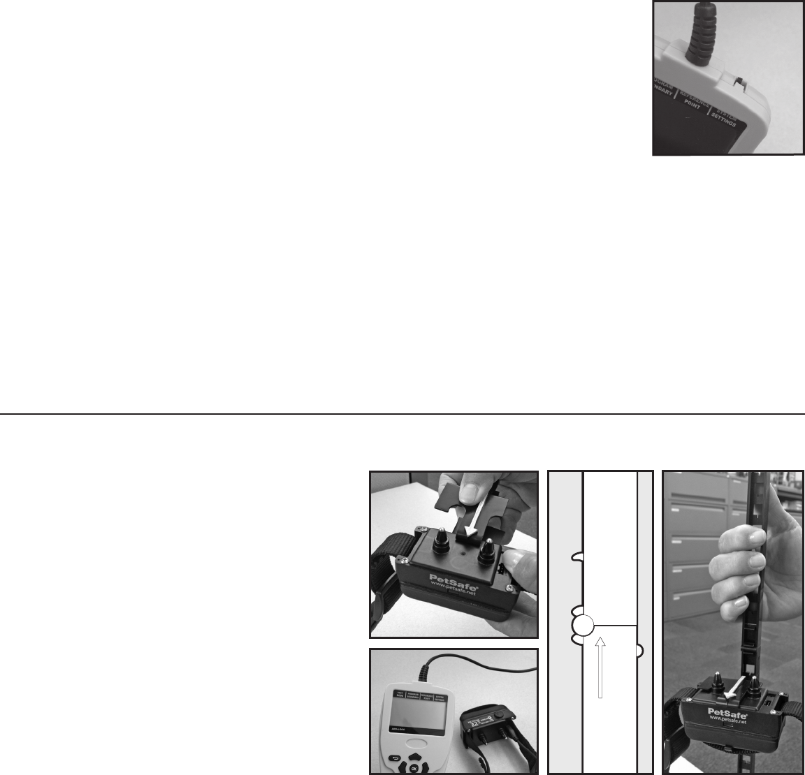
Preparing the Receiver Collar for Programming
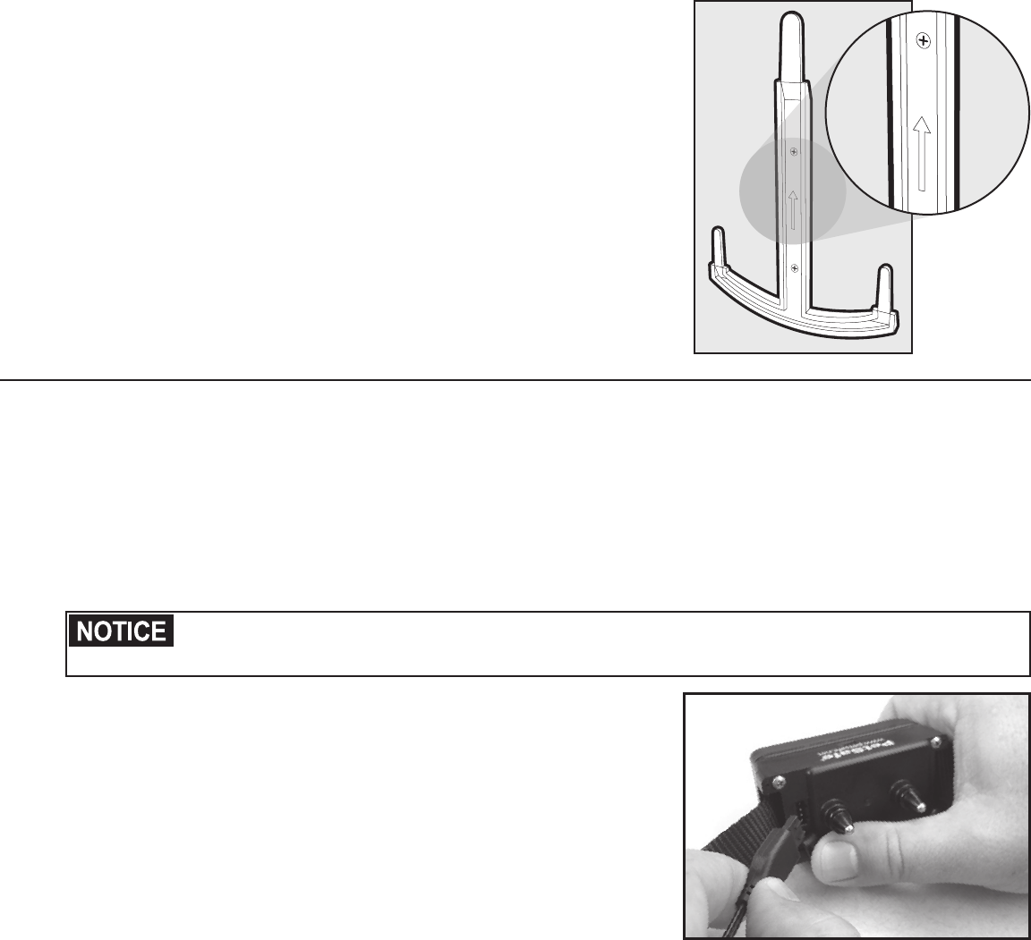
1. Open the Receiver Handle and snap each
section into place to form a long pole.
2. Slide the Receiver Mounting Bracket
on the Receiver Collar before installing
the Receiver Mounting Bracket on the
Receiver Handle. The Receiver Collar must
be installed with the arrow on the Receiver
Mounting Bracket pointing toward the
Receiver Collar PetSafe® logo (5A).
3. Orient Receiver Handle so that the
arrow on the Receiver Handle is pointing
up (5B). Determine the height of your
dog’s neck above the ground and snap
the Receiver Mounting Bracket on the
Receiver Handle to match the height
of your dog’s neck (5C). Important: If
you will be programming multiple dogs,
position the handle to match the height of
your dog’s neck using the shortest dog’s
measurements – closest to the ground.
4. Plug the Boundary Programming Unit into
the Receiver Collar (5D). The cable from
the BPU plugs into the Receiver Collar
charge jack (3A).
5. Turn on the Boundary Programming Unit.
UP
5A 5C5B
5D
Step
4
Step
5
www.petsafe.net 13
Placing the Boundary Flags
Test Mode
The BPU automatically goes to the Test Mode main menu when turned ON. The Test Mode allows you to
test potential boundary flag locations to make sure the flags meet certain requirements. If the flag location
is acceptable, a menu will display that the flag is good and provide an approximate range measurement.
Testing Boundary will not program your system.
If the flag is not acceptable, the BPU will display a message indicating why the location failed. For example,
the location could be too far away from the Transmitter, too close to the Transmitter, or may be in an area of
high signal distortion. Follow the display directions to test your Boundary Flag locations.
Boundary Flag Placement and Distance Verification
In order to verify that the maximum locations of your desired boundary
are within the range limits of the system, place the “corner” flags at the
minimum and maximum distance points of your desired boundary and
test these flags to verify that corner points are within the acceptable 15
feet to 90 feet range from the Transmitter. Once you have verified that
the corner flags are within the acceptable range, fill in the remaining flags.
The maximum number of flags the system can accept is 128. Flags within
30 feet of the Transmitter should be spaced approximately 3 feet apart.
Flags between 30 and 70 feet from the Transmitter should be spaced
approximately 4 feet apart. Flags greater than 70 feet from the Transmitter
should be placed 4 to 5 feet apart. Keep in mind that each flag must have
a unique radial line and the radial lines must not cross with one another
START
POINT
P
R
O
G
R
A
M
B
O
U
N
D
A
R
Y
I
N
C
L
O
C
K
W
I
S
E
D
I
R
E
C
T
I
O
N
.
6A
(See Installation Requirements on Page 8). It is recommended that you number the flags with a permanent
marker to assist in keeping track of the flag numbers when programming the boundary. The first flag should
be at the start of a partial boundary or can be anywhere on a full boundary. The numbering should increase
as you move in a CLOCKWISE direction around the Transmitter (6A).
Testing the Boundary Flag Placement
With the BPU in Test Mode, start at flag 1 and test each flag and verify that each flag is accepted before
moving to the next flag. The BPU will show the distance of each flag in feet from the Transmitter. As you
test the flags monitor the distance readings for changes that are significantly different from one flag to the
next i.e. greater than the actual distances between the flags. Large distance measurements between flags
or a group of flags can indicate possible problems with buried utilities or wires. If possible, avoid these
areas or modify the boundary to minimize the measurement differences observed between the flags. The
measurement distances between two adjacent flags should be equal to or less than the actual distance
measured on the BPU.
Programming the Boundary
This mode allows you to program the boundary you have just set up. You will need to select the type of
boundary that you will be using, Full or Partial. You will collect boundary data at each flag location in a
CLOCKWISE direction around the Transmitter. As in the TEST MODE, the range will be displayed if the flag is
accepted. Otherwise, an error menu will indicate what caused the location to fail. Follow all directions shown
on the BPU display. As a reminder the maximum number of flags is 128. Be sure to point the arrow on the
Receiver Mounting Bracket in a direction away from the Transmitter. While acquiring the boundary data at
each flag, the Receiver should not be moved.
Reference Point
Following programming of all of the flags the BPU will instruct you to move to your Reference Point location.
The Reference Point is a location that can easily be remembered and is permanent (i.e. a corner of a sidewalk
or driveway). The Reference Point must be located 20 to 90 feet from the Transmitter. This Reference Point
location is used to add multiple receivers to the system. Following the programming of the Reference Point,
the Boundary data is calculated, and is programmed into the Receiver. This programming may take several
minutes to complete.
Programming Complete
At the completion of the Receiver Collar programming, the BPU will display that programming is complete.
You may now disconnect the BPU from the Receiver Collar and turn the BPU off. When disconnecting the
BPU, the Receiver Collar will automatically go through the Ready Test Feature and into normal operation
mode. See Step 9 on page 14.
Step
6
Step
7
14 1-800-732-2677
System Settings
This mode allows you to select features to customize the Receiver Collar. Refer to page 19 for further details
on these features.
ADD-A-DOG
This mode is used if multiple Receivers are to be added to the same containment area programmed in the
BPU. Refer to page 20 for further directions on this feature.
Test the Receiver Collar
After you program the boundary, take the Receiver Collar around the boundary and verify that the boundary
programmed correctly. Leave the Receiver Collar on the Receiver Handle while doing this and always move
the Receiver Collar in the direction of the white arrow, i.e., don’t move the receiver back and forth like a
pendulum. Do not walk or move the Receiver Collar backwards.
Approach each flag from the Pet Area, and verify that the Receiver Collar generates the warning tone. This
will vary slightly but should be approximately 3 feet from the Boundary Flag Location. The Boundary Flags
location is where the Receiver activates the Run-Through stimulation level. The Receiver Collar generates
three distinct Warning Tones to assist you in determining the Receiver Activation Status. See alarm tone
description in Receiver Collar Status Indicator table in Step 9.
Walk along the Pet Area, especially around AC power entrances, cable TV and phone line entrances into
the home, and near air conditioning units. Make sure the collar does not tone in the area where your dog
should be free to play. If there are problems, you will need to adjust your layout to exclude these areas or
possibly move your Transmitter to a different location. Reminder: If you move the Transmitter you will need
to reprogram your Boundary.
Test Light Instructions
If there are distractions impeding hearing of
the tone, an alternative detection method
would be to utilize the Test Light Tool. Remove
from the Receiver Handle first.
1. Set the Correction Level to 2 or above.
See Step 9.
2. Hold the Test Light Contacts to the
Receiver Collar Contact Points (8A).
3. PetSafe® logo needs to be forward and
facing the outward direction.
4. Walk toward the Boundary Zone holding
the Receiver Collar at your pet’s neck level
(8B)
until the Test Light flashes (8C).
Save Test Light for future testing.
8B
B
o
u
n
d
a
r
y
Z
o
n
e
Pet
Area
8C
8A
Moving the Boundary Flags to the Warning Zone
The PetSafe® training protocol instructs that the flags be placed at the location of the start of the warning
tone. The flags are the visual cue for the edge of the boundary area. After the boundary has been
programmed and you are satisfied that the boundary is adequate for your intended area, you will need to
move the flags to the location where the warning tone starts activating.
Setting the Warning Zone Width
The Warning Zone width is adjustable using the System Settings menu in the BPU. The Warning Zone width
default setting is Medium. The adjustable ranges are as follows:
•Low: approximately 1 foot warning distance.
•Medium: approximately 3 feet warning distance
•High: approximately 5 feet warning distance
Refer to Page 19 for further information on this feature.
If your boundary flags are close to your house and you need a wider area for your dog to be able to run
through this area, you may want to set your Warning Zone to the minimum distance or Low setting. Please
note with the Warning Zone set to Low, your dog will have very little warning before the higher level Run
Through Prevention Static Correction is generated. If your dog is more stubborn, you may want to set your
Warning Zone to the maximum distance or High setting.
Step
8
www.petsafe.net 15
Placing Flags at Warning Zone
Leave the Receiver Collar on the Receiver handle while performing this and always move the receiver Collar
in the direction of the Arrow on the Receiver Mounting Bracket. Starting from within the Pet Area walk
toward the boundary Flags. Remove the Boundary Flags from programming location and place them at the
point where the Receiver Collar Warning Tone starts. If you have trouble hearing the tone, you may use the
Test Light Tool to see where the test light begins to flash.
After about 15 seconds of anti-linger or normal static correction, the Receiver Collar will enter a timeout
condition, and you must allow for a full 10 seconds recovery time (and be back inside the Pet Area) before
the Receiver Collar will again respond to boundary. If the Receiver Collar fails to detect the boundary, then
timeout is the likely cause. Wait 10 seconds and try again.
When repeatedly testing boundary detection, the Receiver Collar will skip the warning tone and go straight
to the Anti-Linger tone unless the Receiver Collar has been back in the Pet Area for a full 10 seconds since
the last instance of Anti-Linger or Static Correction toning.
Prepare the Receiver Collar
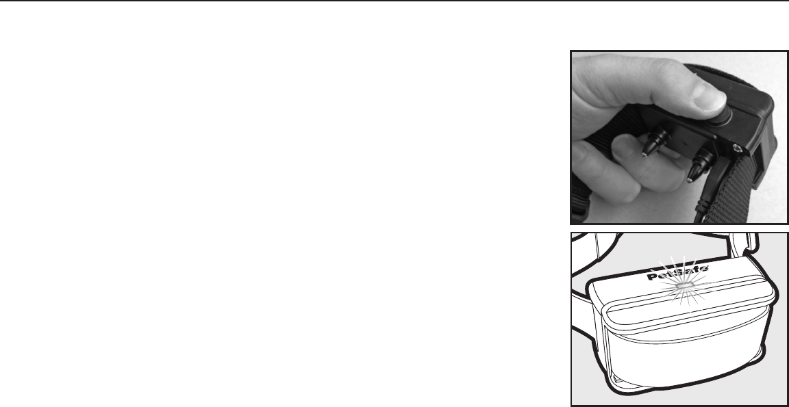
Turning the Receiver Collar ON.
Press and hold the Mode Button continuously for 2 seconds. (9A)
The green or red/green or red Receiver Indicator Light will turn ON for
5 seconds (9B) to indicate battery status, followed by the red Receiver
Indicator Light flashing the Static Correction Level Settings.
Turning the Receiver Collar OFF
Press and hold the Mode Button continuously for 5 seconds (9A). The
red Receiver Indicator Light will be ON during this time. The red Receiver
Indicator Light will then turn OFF and all Receiver Indicator Lights will stay
OFF indicating that the unit is turned OFF.
To extend the time between charging the Receiver Collar, consider turning
OFF the Receiver Collar when it is not in use.
ReadyTest® Feature
ReadyTest® gives you added confidence that the Receiver Collar is
working and ready to use. When you remove the Receiver Collar from
the Charger or turn the collar on with the Mode Button, the receiver will
automatically go into self-test mode for approximately 15 seconds. The
Receiver’s internal diagnostics will check that the battery charge is full and
that all circuits are working correctly. The receiver will also alert you if the
transmitter is not turned on during the self-test verification.
9A
www.petsafe.net
w.p
pe
fe
et
sa
ts
www.petsafe.net
w
w
p
pe
pe
pe
pe
e
tsa
tsa
tsa
tsa
e
e
e
fe
fe
fe
n
w
w
ww
w
w
w
e
e
n
9B
Receiver Collar Status Indicators
The Receiver Collar uses colored LEDs and an Alarm Tone to indicate the functional and operational status of
the receiver. Refer to the Receiver Collar Status Indicator Table to understand the operation of the lights and
tones for the Receiver Collar.
Step
9
16 1-800-732-2677
Receiver Collar Status Indicator Table
Status Light Alarm Tone Condition
While Plugged into Receiver Charger
Solid red No tone Charge in progress
Solid green No tone Charge complete
No light Charge failure, contact
Customer Care Center
ReadyTest® after removing from Receiver charger or turning on the Receiver Collar
Red for 3 seconds / Off for 1 second
Red/green for 3 seconds
Off for 1 second
No tone
Unit is performing internal self test.
Note: For Mode Button turn on Status Light starts
with red/green on for 3 seconds.
Continuous green or red/green or red
(5 second duration) No tone
Battery charge indicator:
Green = 100% - 60%
Red/green = 60% - 20%
Red = 20% or less
Red flash occurring from 1 to 6 times No tone Unit is reporting Static Correction level from 1 to 6
No light 3 note chime,
3 consecutive times Transmitter is turned off or Receiver Collar is out of range
Operating Battery Status
Slow blinking green
(every 4-5 seconds) No tone Collar battery charge 100%-60%
Slow blinking red/green
(every 4-5 seconds) No tone Collar battery charge 60%-20%
Slow blinking red
(every 4-5 seconds) No tone Collar battery charge 20% or less, charge immediately
Receiver Activation Status
Fast pulsating green
(3 flashes per second)
Low frequency
warning tone Receiver collar in Warning Zone area
Fast pulsating red
(3 flashes per second)
Mid frequency
warning tone
Anti-linger static correction being delivered with the
Receiver Collar in the Warning Zone area
Fast pulsating red
(3 flashes per second)
High frequency
warning tone
Run through static correction being delivered with the
Receiver Collar beyond the mapped boundary point area
www.petsafe.net 17
Adjusting the Static Correction Level
The Static Correction Level can be changed by two methods. The first method of changing the correction
level is by pressing the Receiver Collar Mode Button briefly when the unit is turned on. The indicator light
will light red when the button is pressed. When the button is released the unit will flash the red indicating the
Correction Level by the number of times the indicator flashes (See Function and Response Table below). To
change the Static Correction Level, press the mode button within 5 seconds of the last red flash. The Static
Correction Level will then increase one level and report the new level by flashing the number of times again.
Continue to repeat this procedure until the desired static correction level is achieved.
The Static Correction Level can also be changed by connecting the BPU and navigating to the System Setting
screen and selecting the Receiver Settings menu.
Function and Response Table
Indicator Light Response Static Correction Level Receiver Collar Function Temperament of Pet
1 Red Flash 1 No Static Correction, Tone Only Initial Training Mode
2 Red Flashes 2 Low Static Correction Timid
3 Red Flashes 3 Medium-Low Static Correction Timid or Average
4 Red Flashes 4 Medium Static Correction Average Energy
5 Red Flashes 5 Medium-High Static Correction Average or High Energy
6 Red Flashes 6 High Static Correction High Energy
Set the Correction Level at Level 1 (tone only) for the first day of training.
Anti-Linger Prevention
Where Static Correction begins. The Anti-Linger Prevention feature keeps your dog from staying in the
Warning Zone for long periods of time and draining the Receiver Collar battery. Your dog will hear a two
second warning tone when he reaches the Warning Zone. If your dog does not return to the Pet Area after
two seconds, he will receive a continuous Static Correction until he returns to the Pet Area. Once the Static
Correction has started, your dog must remain in the Pet Area for at least 10 seconds to reset the Warning
Tone output. If he re-enters the Warning Zone prior to the 10 second reset period, he will automatically
receive the Anti-Linger Correction upon entering the Warning Zone.
Run-Through Prevention
Higher Level of Static Correction. This system includes a unique “run-through” prevention so that your
dog cannot escape the Pet Area without receiving an increased level of Static Correction. The Receiver
Collar automatically increases the Static Correction when your dog continues beyond the Boundary Flag
Programmed points.
Over Correction Protection
If your pet leaves the Pet Area, this feature limits the Static Correction duration to 15 seconds. While the
system locks out further Static Correction, the green light will remain on for 10 seconds. If your pet returns to
the Pet Area, he will not receive a Static Correction upon return to the Pet Area.
18 1-800-732-2677
Fit the Receiver Collar
Important: The proper fit and placement of your Receiver Collar is important for effective training. The Contact Points
must have direct contact with your pet’s skin on the underside of his neck.
Please read and follow the instructions in this manual. Proper fit of the collar is important. A collar
worn for too long or made too tight on the pet’s neck may cause skin damage. Ranging from redness
to pressure ulcers; this condition is commonly known as bed sores.
• Avoid leaving the collar on the dog for more than 12 hours per day.
• When possible reposition the collar on the pet’s neck every 1 to 2 hours.
• Check the fit to prevent excessive pressure; follow the instructions in this manual.
• Never connect a lead to the electronic collar; it will cause excessive pressure on the contacts.
• When using a separate collar for a lead, don’t put pressure on the electronic collar.
• Wash the dog’s neck area and the contacts of the collar weekly with a damp cloth.
• Examine the contact area daily for signs of a rash or a sore.
• If a rash or sore is found, discontinue use of the collar until the skin has healed.
• If the condition persists beyond 48 hours, see your veterinarian.
• For additional information on bed sores and pressure necrosis, please visit our website.
These steps will help keep your pet safe and comfortable. Millions of pets are comfortable while they
wear stainless steel contacts. Some pets are sensitive to contact pressure. You may find after some
time that your pet is very tolerant of the collar. If so, you may relax some of these precautions. It is
important to continue daily checks of the contact area. If redness or sores are found, discontinue use
until the skin has fully healed.
You may need to trim the hair in the area of the Contact Points. Never shave the dog’s neck; this may
lead to a rash or infection.
Your Receiver Collar comes with Short Contact Points installed. Use the Long Contact Points for pets with
long or thick hair. Check tightness weekly.
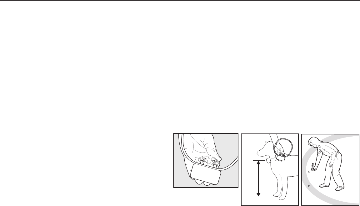
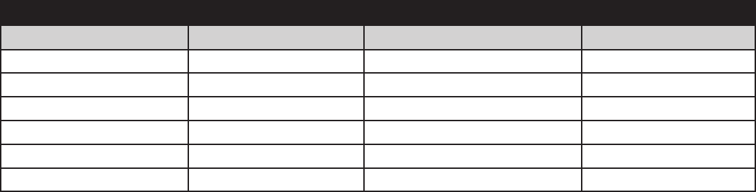
To assure a proper fit, please follow these steps:
1. Make sure Transmitter is not plugged in, and
the receiver is turned off.
2. Start with your pet standing comfortably
(10A).
3. Make sure PetSafe® logo is upright, facing
the dog’s chin (10B).
4. Center the Contact Points underneath your
pet’s neck, touching the skin.
10B
10A
You may need to trim the hair in the area of the Contact Points. Never shave the dog’s neck; this may
lead to a rash or infection.
5. Check the tightness of the Receiver Collar by inserting one
finger between the end of a Contact Point and your pet’s
neck. The fit should be snug but not constricting (10B).
6. Allow your pet to wear the collar for several minutes then
recheck the fit. Check the fit again as your pet becomes
more comfortable with the Receiver Collar.
7. Trim the collar as follows (10C):
a. Mark the desired length of the Receiver Collar with a pen.
Allow for growth if your pet is young or grows a thick
winter coat.
b. Remove the Receiver Collar from your pet and cut off the
excess.
c. Before placing the Receiver Collar back onto your pet,
seal the edge of the cut collar by applying a flame along
the frayed edge.
10C
10B
Step
1
0
www.petsafe.net 19
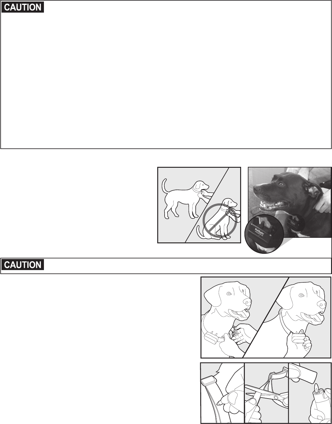
To Re-Thread the Collar
Slide Buckle
Ridges
The slide buckle prevents the collar from becoming loose
around your pet’s neck.
The ridges must be facing up; the collar will slip if it is
not properly threaded.
Always remove the Receiver Collar from your pet when indoors to avoid accidental activation of the
Receiver Collar.
System Settings Menus and Description
Within the BPU system settings are user selectable features that allow you to customize the way the system
functions. This section describes each of these features and how they function.
Receiver Settings
Correction Level: Used to program the Static Correction Level into the Receiver Collar. You can select levels from 1
to 6. Level 1 is tone only and produces no static correction output. Levels 2 through 6 produce both tone and Static
Correctionn outputs. Level 2 is the lowest level and 6 is the highest level. Note: These Static Correction Levels can
also be changed without using the BPU. The Mode Button on the receiver will also allow you to change the Static
Correction Level.
Warning Zone Width: Used to program the Warning Zone distance from the Boundary Flag Programmed points.
You can select three distances, Min, Average, and Max. These distances correspond to 1 foot, 3 foot and 5 foot
respectively. The default setting is the Average warning zone width.
Max Range Correction, Enable Correction beyond maximum Transmitter Range: This feature is used in
conjunction with a partial boundary. Enabling this feature protects your dog from wandering away from the
unprogrammed portion of the boundary. For example, if you have a partial boundary in your back yard and the
dog escapes out your front door, the Receiver Collar will generate a Static Correction when the dog reaches
the maximum Transmitter range if this feature is enabled. The maximum Transmitter range that the Receiver will
generate a Static Correction is approximately 110 feet. The default setting is YES which enables this feature.
Sleep Mode: Enable Sleep Mode to extend battery life. This feature is used to program whether the Receiver
Collar is allowed to go into a Sleep Mode to conserve battery life when your dog is not moving. For the Receiver
Collar to go into the Sleep Mode the Receiver Collar location must be at least 20 feet away from the programmed
boundary, at least 12 feet away from the Transmitter, and must have remained in the same location (i.e. not more
than 6 inches of movement) for at least 15 seconds. Under typical conditions the battery life with sleep mode
enabled should be 10 to 14 days. With the Sleep Mode disabled, the battery life is reduced to approximately 7
days. The default setting is YES which enables this feature.
Battery Status: Used to determine the charge status of the receiver battery. Before starting to program a
boundary, make sure that the Receiver Collar is fully charged.
Boundary Status: Used to verify that a valid boundary has been programmed into the Receiver Collar.
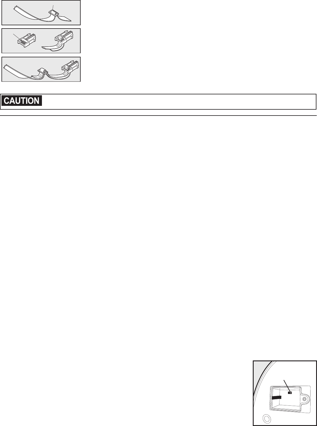
Transmitter Settings
This feature is used to program the Receiver Collar to the operating frequency mode
of the Transmitter. This containment system is capable of operating on two different
frequencies. This feature is utilized when two containment systems are operating in close
proximity to one another. The Paw Point Custom Wireless Fence will not function properly
if you and your neighbor have the Paw Point Custom Wireless Fence operating on the
same frequency mode and the transmitters are located within 120 feet of each other.
This feature only changes the operating frequency mode of the receiver. The Transmitter
contains a frequency mode switch on the rear of the housing (10D), accessed through
a panel labeled Mode Selection Switch. The default setting is Mode A. Likewise the
Transmitter Mode Selection Switch is set to Mode A from the factory.
BA
Frequency
Switch
10D
20 1-800-732-2677
System Information
PIC Version, MSP Version, Receiver Version, Error Log: These features are used to access the operating software
versions that are programmed into the BPU and Receiver Collar and the Error Log. These features are intended to
be used when contacting Customer Care to assist in troubleshooting certain problems that might occur.
Reset All
This feature is used to restore all of the user selectable settings back to the factory default settings.
ADD-A-DOG / Programming Additional Collars
To add multiple dogs to your system, first charge the additional Receiver Collars. Attach the new Receiver
collar to the Receiver Mounting Bracket and the Receiver Handle. Turn on the BPU and plug the PBU cable
into the Receiver Collar. Walk to your Reference Point in your yard. Move the BPU curser to the ADD-A-
DOG position, press OK, and follow the BPU directions. Once you receive the message that programming is
compete, disconnect the Receiver Collar, turn off the BPU and verify that receiver is operating properly with
the Warning Zone and Static Correction Areas.
Training Guide
Be Patient With Your Pet
Important: Proper training of your pet is essential to the success of the PetSafe® Paw Point
Custom Wireless Fence. Read this section completely before beginning to train your pet.
Remember that the PetSafe® Paw Point Custom Wireless Fence is not a solid barrier.
•Have fun with your pet throughout the training process. Training should be
fun, fair, firm and consistent.
•Train for 10 to 15 minutes at a time. Don’t try to do too much too
quickly. More-frequent short sessions are better than less-frequent
longer sessions.
•We suggest a minimum of 14 days of training. Depending on your pet
and how he learns, the training could take more or less time.
•If your pet shows signs of stress, slow down the training schedule, add
additional days of training, or increase the amount of play time with your
pet in the Pet Area. Common stress signals include:
-Pet pulling on leash toward the house
-Ears tucked
-Tail down
-Body lowered
-Nervous / frantic movement or stiffening of pet’s body
•Your pet must be completely comfortable near the Boundary Flags at the end of every training
session. Spend at least 5 minutes of “play time” at the completion of each session within 10 feet of
the Boundary Flags.
•Finish each training session on a positive note with lots of praise and play.
•Remove the Receiver Collar after each training session.
•Be sure to contain your pet by another means during the training period (e.g. pen, tie-out, leash,
etc.).
•During training, if you need to take your pet out of the Pet Area, remove the Receiver Collar and
either pick your pet up or put him in the car to pass out of the Pet Area.
•Even if you think your pet is responding well to the training, complete the entire training.
Reinforcement is important!
1234567
8910 11 12 13 14
15 16 17 18 19 20 21
22 23 24 26 27 28
29 30 31
SMTWTFS
25
30
0
15
min.
45
www.petsafe.net 21
Day 1 - Boundary Awareness
Tone Only Training Mode
Perform three sessions on day 1, each training session lasting 10-15 minutes.
Goal:
To have your pet learn that the Boundary Flags and warning beep from the Receiver Collar define the
new Pet Area.
Setup:
•Program the Static Correction Level on the Receiver Collar to Level 1 Tone Only training mode.
•Put a separate non-metallic collar on your pet’s neck ABOVE the Receiver Collar and attach a leash.
Be sure the extra collar does not put pressure on the Contact Points.
•Have tiny pieces of treats that your pet will find desirable available (hot dogs or lunch meat work
well).
•Have your pet’s favorite play toy available.
Steps:
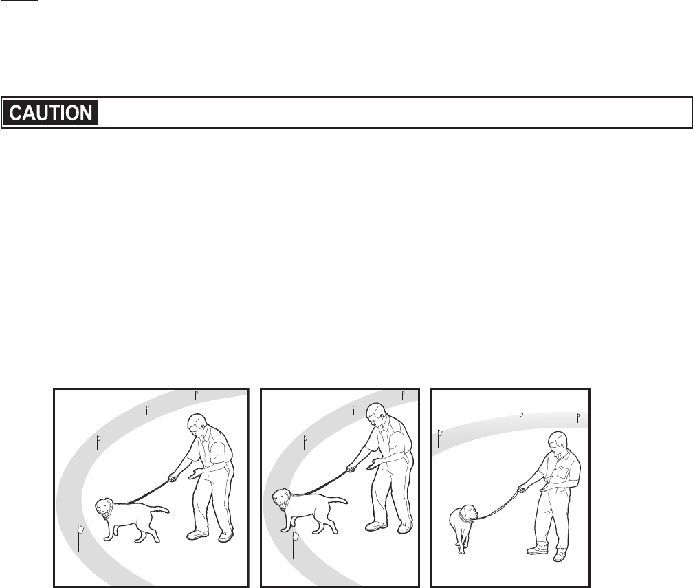
1. Begin by walking your pet on a leash in the Pet Area. Calmly praise and talk to your pet.
2. Move toward the Boundary Flags (1A). Keep your mood happy.
3. With full control of your pet on a leash, walk to the flags. As your pet enters the Boundary Zone, the
Receiver Collar will begin to beep (1B). Allow your pet to stay in the Boundary Zone for up to 2 seconds
then gently help him back into the Pet Area (1C). Immediately praise and offer your pet a treat as he
enters the Pet Area, even if you have helped with the leash.
4. Repeat this process at the same Boundary Flag until your pet resists going into the Boundary
Zone.
5. Aim to master 3-4 Boundary Flags per session. Make this FUN! Praise if your pet quickly retreats
or resists going into the Boundary Zone.
1A 1B 1C
Phase
1
22 1-800-732-2677
Days 2 thru 4 - Continue Boundary Awareness
Introduction to Static Correction
Perform three sessions per day, each lasting 10-15 minutes.
Goal:
To train your pet to stay in the Pet Area and respect the boundary.
Setup:
•Program the Static Correction Level on the Receiver Collar to Level 2.
•Put a separate non-metallic collar on your pet’s neck ABOVE the Receiver Collar and attach a leash.
Be sure the extra collar does not put pressure on the Contact Points.
•Have tiny pieces of treats available (hot dogs or lunch meat work well).
•Have your pet’s favorite play toy available.
Steps:
1. Repeat steps 1-5 in Phase One.
2. If your pet does not respond to the Static Correction, confirm that the Receiver Collar is fitting properly
according to Step 10 on page 17.
3. If the Receiver Collar is fitted properly and your pet does not respond to the Static Correction, increase
the Static Correction Level by 1. Watch for slight reactions at first such as ears up, head turned, looking
at the ground.
4. Stay at the same flag until your pet resists going into the Boundary Zone.
Days 5 thru 8 - Distraction Phase
Perform three training sessions per day, each lasting 10 to 15 minutes.
Goal:
To train your pet to stay within the Pet Area with distractions outside of the Pet Area.
Setup:
•Program the Static Correction Level on the Receiver Collar to level 2 or higher depending on the reaction
results from days 2 thru 4.
•Put a separate non-metallic collar on your pet’s neck ABOVE the Receiver Collar and attach a leash.
Be sure the extra collar does not put pressure on the Contact Points.
•Have tiny pieces of treats available (hot dogs or lunch meat work well).
•Have your pet’s favorite play toy available.
•Create distractions to tempt your pet to enter the Boundary Zone, such as:
-Have a family member cross from inside the Pet Area to outside of it.
-Throw a ball or treat outside of the Pet Area.
-Have a neighbor walk their pet outside of the Pet Area.
•Gradually increase distraction level. Never coax or call your pet out of the Pet Area.
Steps:
1. With full control of your pet on a leash, have the distraction presented.
2. If your pet does not move toward the distraction, praise and offer a treat.
3. If your pet does react to the distraction, allow him to go into the Boundary Zone.
4. Help your pet back into the Pet Area if he does not turn back after 2 seconds.
5. Treat and praise your pet anytime he comes back into the Pet Area with or without help.
6. Repeat this process with other distractions. Use other family members during this process.
7. If your pet does not respond to the Static Correction, confirm that the Receiver Collar is fitting properly
according to Step 10 on page 17.
8. If the Receiver Collar is fitted properly and if your pet does not respond to the Static Correction, increase
the Static Correction Level by 1.
Phase
2
Phase
3
www.petsafe.net 23
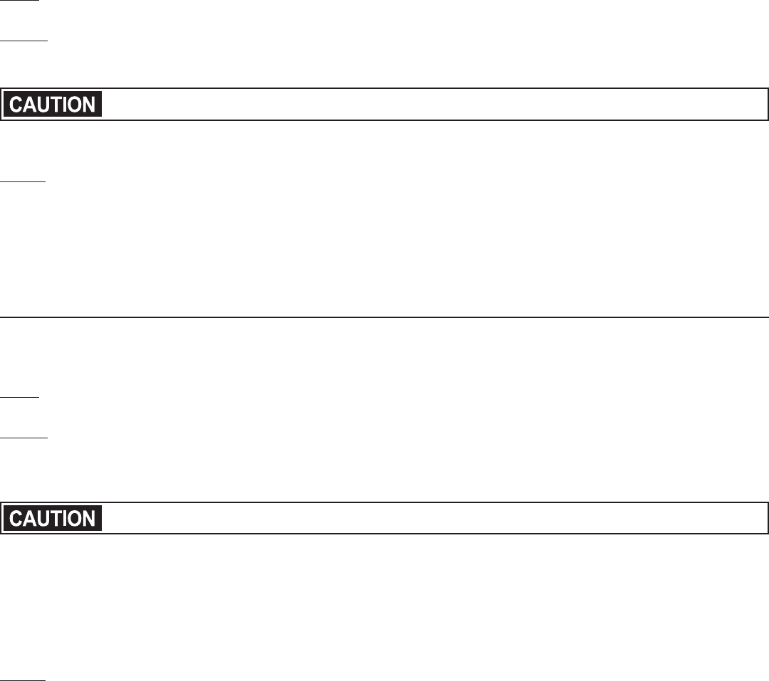
Days 9 thru 14 - Unleashed Supervision
Training sessions should start at 10-15 minutes, gradually increasing to over an
hour.
Your pet is ready for this step only when he clearly avoids the entire Boundary
Zone, regardless of any distractions or temptations. During this step, do not
leave your pet unattended.
Goal:
To give your pet free run of the Pet Area off the leash.
Setup:
Adjust the Receiver Collar to the permanent setting appropriate for your pet.
Steps:
1. Enter the Pet Area with your pet wearing the Receiver Collar.
2. Walk around the yard and play with your pet, staying within the Pet Area at all times.
3. Preoccupy yourself with another task in the yard while watching your pet.
Days 15 thru 30 - Pet Monitoring
Your pet is ready to run! Check in on your pet at regular intervals.
Note: After you are satisfied your pet’s training is complete, remove every other Boundary Flag every 4 days
until all flags are removed. Save Boundary Flags for future use.
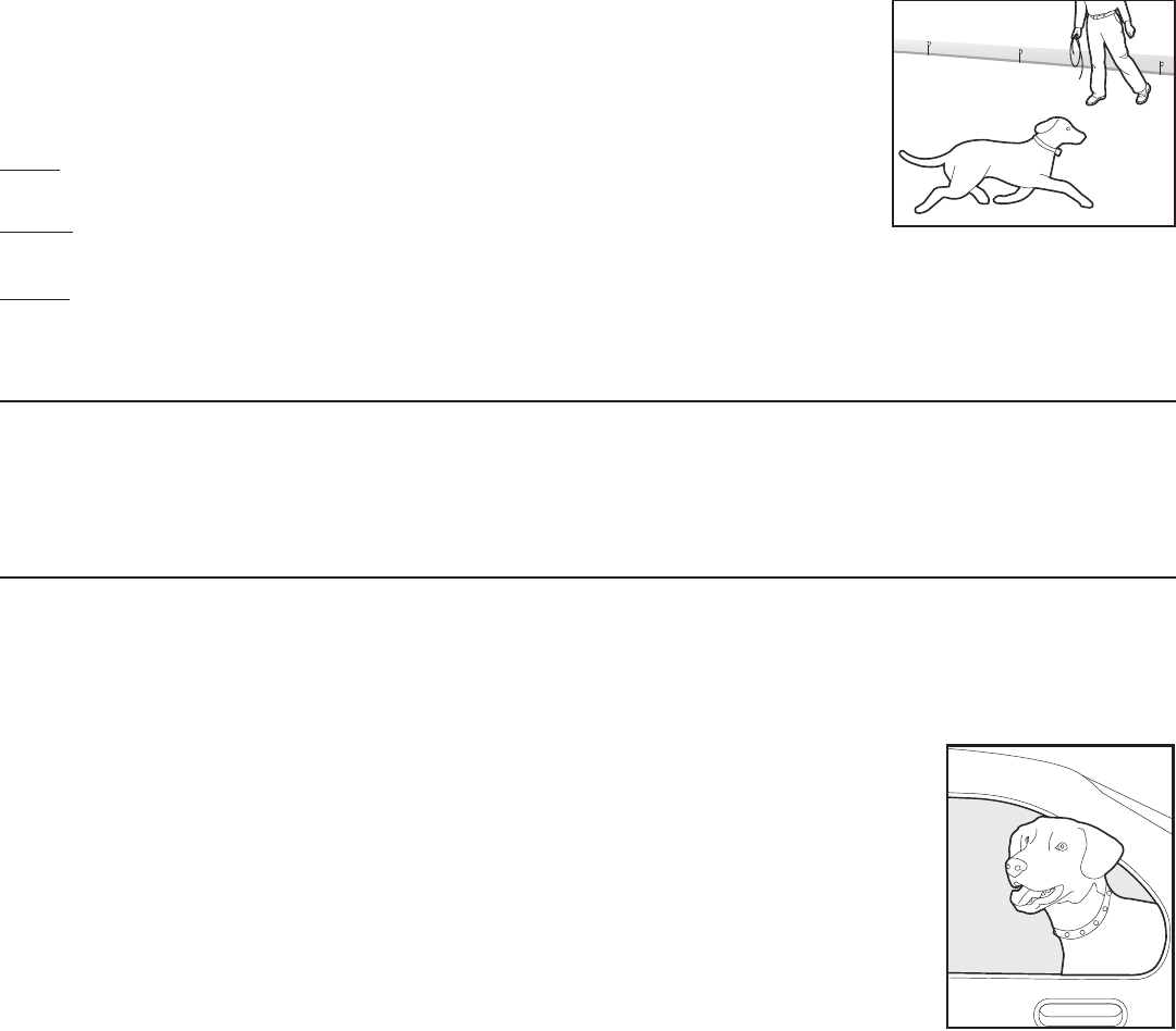
Taking Your Pet Out of the Pet Area
Important: Remove the Receiver Collar and leave it in the Pet Area.
Once your pet learns the Boundary Zone, he will be reluctant to cross it for walks
or car rides.
Option 1: Replace the Receiver Collar with a regular collar. Put your pet in a car that is within
the Pet Area and drive him out of the Pet Area.
Option 2: Replace the Receiver Collar with a regular collar and leash. Walk your pet out of the
Pet Area while giving a command such as “OK” at a specific place of the Boundary Zone (the
end of your driveway, sidewalk, etc.). Always leave the Pet Area with a leash at this place and
your pet will associate leaving the Pet Area only on a leash, only at this place, and only with a
person. You may initially need to convince your pet to leave the Pet Area with a food treat and
lots of praise.
Note: You may also carry your pet out of the Pet Area.
Congratulations!
You have now
successfully completed
the training program.
Phase
4
Phase
5
24 1-800-732-2677
Accessories
To purchase additional accessories for your PetSafe® Paw Point Custom Wireless Fence, contact the Customer Care
Center at 1-800-732-2677 or visit our website at www.petsafe.net to locate a retailer near you.
Component Part Number
Extra Receiver Collar PIF00-13652
Extra Receiver Collar Charger PIF00-13981
Extra Boundary Flags RFA-2
Receiver Collar Strap RFA-491
Transmitter with Mounting Bracket and Hardware PIF00-13984
Boundary Programming Unit (BPU) PIF00-13982
Transmitter Mounting Bracket and Hardware PIF00-13985
Transmitter Adapter PIF00-13986
Receiver Handle and Receiver Mounting Bracket PIF00-13983
Short Contact Points RFA-262
Long Contact Points RFA-263
Frequently Asked Questions
Is the Receiver Collar waterproof? •Yes.
Will a sloping yard or hills affect the
Pet Area?
•No. The Transmitter signal extends up to 90 feet in all directions. A
sloping yard or a yard with hills can cause the Pet Area to appear less or
more than expected. Consider repositioning the Transmitter to maximize
your Pet Area. Reminder: By moving your Transmitter you will need to
reprogram your Boundary.
Can I use more than one Receiver
Collar with the Paw Point Custom
Wireless Fence?
•Yes. There is no limit to the number of pets you can contain with the Paw
Point Custom Wireless Fence. You must purchase an additional Receiver
Collar for each pet. Contact the Customer Care Center at 1-800-732-2677
or visit our website at www.petsafe.net to locate a retailer near you.
Will the Paw Point Custom Wireless
Fence keep other pets out of my
yard?
•No. The Paw Point Custom Wireless Fence is only effective on pets who
wear the Receiver Collar.
Is there a hand-held remote
Transmitter that will work with the
Receiver Collar?
•No. You would need to purchase a separate Remote Training System.
Contact the Customer Care Center at 1-800-732-2677 or visit our website
at www.petsafe.net to locate a retailer near you.
If I have a question about my Paw
Point Custom Wireless Fence or
need replacement parts, where can I
get answers or service?
•Contact the Customer Care Center at 1-800-732-2677 or visit our web
site at www.petsafe.net.
Can I use the Paw Point Custom
Wireless Fence on an aggressive
pet?
•This product is not for use with aggressive pets. If you are unsure if your
dog is aggressive, please consult your veterinarian or a certified trainer.
Can I use the Paw Point Custom
Wireless Fence on a cat?
•The Paw Point Custom Wireless Fence can be used as long as the cat can
comfortably wear the Receiver Collar and is 15 lbs. or larger..
What happens if the power goes
out?
•The Paw Point Custom Wireless Fence is designed to recognize power
outages and shuts down without activating the Receiver Collar.
If my pet leaves the Pet Area, how
long will he be corrected?
•Your pet will receive Static Correction for up to 15 seconds as long as he
is outside the Pet Area.
How often do I need to charge the
Receiver Collar battery?
•Each charge can last up to 2 weeks depending upon frequency of use.
The Receiver Indicator Light acts as a
low battery indicator, flashing red every 4 to 5 seconds when battery
charging is required.
Can I place the Receiver on another
collar?
•Yes. You may use any 1 inch, non-metallic collar.
www.petsafe.net 25
Do I need to perform maintenance
on my Paw Point Custom Wireless
Fence?
•Yes. Check your pet’s neck daily for irritation from the Contact Points.
•Check the Contact Points on the Receiver Collar weekly to make sure they
are clean.
•The Contact Points are designed to be hand tightened. Do not over tighten.
•Check the fit of the Receiver Collar weekly.
•The Receiver Indicator Light acts as a Battery Status Indicator, flashing red
every 4 to 5 seconds when battery charging is required.
How do I know the battery in the
Receiver Collar is charged?
•Check Battery Status Indicator Lights. Light will flash green or red/green
or red indicating the charge status of the battery.
Will vehicles, buildings and landscape
features (trees, shrubs, etc.) affect
the performance of the
Paw Point
Custom Wireless Fence
?
•Yes. Placing the Transmitter inside a metal building can reduce the maximum
range of the Paw Point Custom Wireless Fence.
•Parking a vehicle near the boundary, can reduce the range in that area and
cause your pet to receive a Static Correction where it otherwise would not if
the vehicle was not there.
•Fixed large metal objects such as metal sheds can affect the signal by
reducing the maximum range of the system at the location of the object.
What do I do if my pet’s neck
becomes red and irritated?
•This condition is due to the Contact Points irritating the skin. Discontinue
use of the Receiver Collar for a few days. If the condition persists beyond
48 hours, see your veterinarian. Once the skin returns to normal, replace
the Receiver Collar and monitor the skin condition closely.
Can I attach a leash to the Receiver
Collar?
•No. This can result in pulling the Contact Points too tightly against your
pet’s neck or the collar may break. Attach a leash to a separate, non-
metallic collar positioned above the Receiver Collar.
Why does my Receiver Collar have a
tone only mode?
•The tone only mode can be used in training your pet to his boundary or for
well-trained pets that no longer require Static Correction.
What is the maximum distance the
Receiver Collar can operate from the
Transmitter?
•90 feet.
Troubleshooting
The Receiver Collar is not beeping
when setting up the Warning Zone.
•Make sure Receiver Collar is turned on and Battery Status Lights are
flashing every 4-5 seconds
•Charge Receiver Collar
•The beep may be difficult to hear in a noisy environment.
•Use Test Light as explained in the “Test Light Instructions” section, and
use it to determine the location of Warning Zone.
The Receiver Collar is not beeping or
administering a Static Correction.
•Make sure Receiver Collar is turned on and Battery Status Lights are
flashing every 4-5 seconds
•Charge Receiver Collar
•Check that the Transmitter is plugged into a working AC outlet, the
Power Light is on.
The Receiver Collar is beeping inside
the house.
•It is recommended to remove the Receiver Collar from your pet when
indoors to avoid activation of the Receiver Collar.
My pet is receiving a Static
Correction in his metal crate.
•The Receiver Collar activates when it loses the Transmitter signal. The
metal crate may block the Transmitter signal which causes the Receiver
Collar to activate.
•Remove the Receiver Collar from your pet before placing him in his metal
crate.
The Warning Zone seems to
fluctuate.
•This is normal for the electromagnetic field of the Paw Point Custom
Wireless Fence. The field may be affected by surrounding “electronic
noise,” which can cause it to fluctuate up to 5%.
•Where the Receiver Collar activates is influenced by the speed and
orientation of the Receiver Collar as your pet enters the
Warning
Zone.

26 1-800-732-2677
The Receiver Collar activates in the
middle of the yard.
•The Receiver Collar activates when it loses the Transmitter signal. This
sometimes occurs if a large metal object is between the Receiver Collar
and Transmitter, if the orientation of the Receiver Collar changes near the
Warning Zone, or if the surrounding “electronic noise” interferes with the
signal. If this continues to occur, consider relocating the Transmitter and
resetting the Pet Area.
•Connect the BPU to the Receiver Collar and test the areas of the yard where
the Receiver Collar is activating. There may be something underground that
may be causing the Transmitter signal to be distorted in that area.
The Receiver Collar is beeping but
my pet is not responding to the
Static Correction.
•Make sure the Static Correction Level is set at 2 or above.
•Test the Receiver Collar with the Test Light.
•If the Test Light flashes, check the fit of the Receiver Collar.
•Trim your pet’s fur where the Contact Points touch the neck and/or switch
to the longer Contact Points.
•Contact Points must be in contact with dog’s skin.
•Increase the Static Correction Level.
•Repeat training steps to reinforce training.
My pet reacts strongly to the Static
Correction and has become fearful.
•Lower the Static Correction Level.
•Make sure you are in control of the situation when your pet receives his first
Static Corrections (have him on a leash attached to a separate, non-metallic
collar) and lead him into the Pet Area and praise him. If your pet remains
fearful, suspend training and start again the next day. Make sure to end all
training sessions on a positive note with lots of praise and play.
•Make sure the Transmitter Power Switch is turned on.
The Transmitter Power Light is not
on.
•Make sure the Power Light on the Power Adapter is on when plugged into
a working AC power wall outlet.
•Make sure the Transmitter Power Switch is turned on.
•If Power Adapter Light is not on, contact the Customer Care Center for a
replacement Power Adapter.
The Receiver Collar has injured my
pet’s neck.
•Failing to follow the important safety information at the front of the
Operating and Training Guide has caused pressure ulcers. Some
descriptions of advanced pressure ulcers describe the sores as looking
like burns on the dog’s neck. Be assured that electronic collars do not use
enough energy to create electrical burns. The energy in an output pulse is
only a few thousandths of a Joule; it is similar in nature to the static pulse
that you may feel when you touch a door knob. In some cases, pressure
ulcers are described as chemical burns. The battery in your Receiver
Collar is sealed, in addition, your collar’s housing is also sealed. This
redundant sealing makes it virtually impossible, without misuse or abuse,
for your Receiver Collar battery to leak onto your pet’s neck. Please
review and follow the important safety information on page 2, and the
instructions in Step 10 under the heading “Fit the Receiver Collar” on
pages 18 and 19.

www.petsafe.net 27
Terms of Use and Limitation of Liability
1. Terms of Use
This Product is offered to you conditioned upon your acceptance without modification of the terms, conditions and
notices contained herein. Usage of this Product implies acceptance of all such terms, conditions, and notices.
2. Proper Use
This Product is designed for use with pets where training is desired. The specific temperament of your pet may not
work with this Product. If you are unsure whether this is appropriate for your pet, please consult your veterinarian or
certified trainer.
3. No Unlawful or Prohibited Use
This Product is designed for use with pets only. This pet training device is not intended to harm, injure or provoke. Using
this Product in a way that is not intended could result in violation of Federal, State or local laws.
4. Limitation of Liability
In no event shall Radio Systems® Corporation be liable for any direct, indirect, punitive, incidental, special or
consequential damages, or any damages whatsoever arising out of or connected with the use or misuse of this
Product. Buyer assumes all risks and liability from the use of this Product.
5. Modification of Terms and Conditions
Radio Systems® Corporation reserves the right to change the terms, conditions and notices under which this Product is
offered.
Compliance
FCC/Canada
This Class B digital apparatus complies with Canadian ICES-003. This equipment has been tested and found to comply
with the limits for a Class B digital device, pursuant to Part 15 of the FCC Rules. These limits are designed to provide
reasonable protection against harmful interference when the equipment is operated in a residential environment. This
equipment generates, uses, and can radiate radio frequency energy and, if not installed and used in accordance with
the instruction guide, may cause harmful interference to radio communications. However, there is no guarantee that
interference will not occur in a practical installation. If this equipment causes harmful interference to radio or television
reception, which can be determined by turning the equipment off and on, the user is encouraged to try to correct the
interference by one or more of the following measures:
•Relocate the interfered receiving antenna.
•Increase the separation between the equipment and receiver.
•Connect the equipment into an outlet on a circuit different from that to which the receiver is connected.
•Contact the Customer Care Center at 1-800-732-2677.
This device complies with part 15 of the FCC Rules. Operation is subject to the following two conditions: (1) This
device may not cause harmful interference, and (2) this device must accept any interference received, including
interference that may cause undesired operation. This device complies with Industry Canada licence-exempt RSS
standard(s). Operation is subject to the following two conditions: (1) this device may not cause interference, and (2)
this device must accept any interference, including interference that may cause undesired operation of the device.
Unauthorized changes or modifications to the equipment, not approved by Radio Systems
®
Corporation, could result in
not meeting compliance with FCC regulations and void the user’s authority to operate the equipment.
Australia
This device complies with the applicable EMC requirements specified by the ACMA (Australian Communications and
Media Authority).
Customer Care International
USA & Canada - Tel: 800-732-2677
Monday - Friday 8 AM - 8 PM / Saturday 9 AM – 5 PM
Australia - Tel: 1800 786 608
Monday - Friday 8:30 AM - 5 PM
New Zealand - Tel: 0800 543 054
Monday - Friday 10:30 AM - 7 PM
This product has the benefit of a limited manufacturer’s warranty. Details of the warranty applicable to this product and its
terms can be found at www.petsafe.net and/or are available by sending a stamped addressed envelope to PetSafe® Ltd.
Redthorn House, Unit 9, Chorley West Business Park, Ackhurst Road, Chorley, Lancashire PR7 1NL, United Kingdom.
Radio Systems® Corporation
10427 PetSafe Way
Knoxville, TN 37932
1-800-732-2677
www.petsafe.net
Protected by US Patent 7,656,291 B2.
400-1630
©2012 Radio Systems Corporation