Radio Systems 320103 ELECTRONIC SMARTDOOR User Manual 400 900 11 9 indd
Radio Systems Corp ELECTRONIC SMARTDOOR 400 900 11 9 indd
USERS MANUAL
Operating Guide
Guide d’emploi
Guia para el uso
Model Numbers: PPA11-10711 Small, PPA11-10709 Large
Numéros de modèles : Petit PPA11-10711, Grand PPA11-10709
Números de modelo: PPA11-10711 Pequeño, PPA11-10709 Grande
Please read this entire guide before installing.
Veuillez lire tout ce manuel avant de commencer.
Por favor, lea completamente esta guía antes de comenzar.

2 1-800-732-2677
Important Safety Information
Explanation of Attention Words and Symbols used in this guide
This is the safety alert symbol. It is used to alert you to potential personal
injury hazards. Obey all safety messages that follow this symbol to avoid
possible injury or death.
WARNING WARNING indicates a hazardous situation which, if not avoided, could
result in death or serious injury.
CAUTION CAUTION, used with the safety alert symbol, indicates a
hazardous situation which, if not avoided, could result in minor or
moderate injury.
NOTICE
NOTICE is used to address safe use practices not related to
personal injury.
WARNING • When children are present in the home, it is important to consider the
pet door during child proofi ng activities. The pet door may be misused
by a child resulting in the child accessing potential hazards that may
be on the other side of the pet door. Purchasers/Homeowners with
swimming pools should ensure that the pet door is monitored at all
times and that the swimming pool has adequate barriers to entry.
If a new hazard is created inside or outside of your home, which
may be accessed through the pet door, Radio Systems® Corporation
recommends that you properly guard access to the hazard or remove
the pet door. The closing panel or lock, if applicable, is provided
for aesthetic and energy effi ciency purposes and is not intended
as a security device. Radio Systems® Corporation will not be liable
for unintended use and the purchaser of this product accepts full
responsibility for oversight of the opening it creates.
• Power Tools. Risk of severe injury; follow all safety instructions for
your power tools. Be sure to always wear your safety goggles.
CAUTION The user, prior to installation, must become familiar with all building
codes that may affect the installation of the pet door and determine,
along with a licensed contractor, its suitability in a given installation.
This pet door is not a fi re door. It is important for the owner and
contractor to consider any risks that may be present inside or outside of
the pet door, and any risks that may be created by subsequent changes
to your property and how they may relate to the existence and use,
including misuse of the pet door.
NOTICE
• Keep these instructions with important papers; be sure to
transfer these instructions to the new owner of the property.
• Unauthorized changes or modifi cations may void the user’s
authority to operate this equipment, and void the warranty.
www.petsafe.net 3
Thank you for choosing the PetSafe® brand. You and your pet deserve a companionship that
includes memorable moments and a shared understanding together. Our products and training
tools promote a lifestyle of protection, teaching, and love—essentials that infl uence memories
for a lifetime. If you have any questions about our products or training your pet, please visit our
website at www.petsafe.net or contact our Customer Care Center.
PRODUCT WARRANTY
To get the most protection out of your warranty, please register your product within 30 days at
www.petsafe.net. By registering and keeping your receipt, you will enjoy the product’s full
warranty and should you ever need to call the Customer Care Center, we will be able to help you
faster. Most importantly, PetSafe® will never give or sell your valuable information to anyone.
Complete warranty information is available online at www.petsafe.net.
________________________________________________________________________________
Table of Contents
Components .....................................................................................................................4
Tools Needed .................................................................................................................... 4
How the SmartDoor™ Works ................................................................................................ 4
Install the SmartDoor™ Through a Wall with the SmartDoor™ Conversion Kit ............................... 4
Key Defi nitions .................................................................................................................. 4
PREPARE
A. Place Batteries in SmartDoor™ ...................................................................................... 5
B. Place Battery in SmartKey™ .......................................................................................... 6
C. Check Operational Mode Before Installation ................................................................... 6
D. Check SmartDoor™ Location Before Installation .............................................................. 7
INSTALL
Installing your SmartDoor™ .............................................................................................. 7
SET
A. Setting SmartDoor™’s Sensitivity Level ........................................................................ 10
B. Understanding Sensitivity and the Active Area .............................................................. 10
C. Programming a New SmartKey™ ................................................................................. 11
D. Attaching SmartKey™ to Collar .................................................................................... 11
OPERATE
Operating Your SmartDoor™ ........................................................................................... 11
Troubleshooting Chart ...................................................................................................... 11
Revert SmartKey™ to Factory Default Settings ...................................................................... 12
Clear SmartKey™ Memory ................................................................................................. 12
Replacement Parts and Accessories .................................................................................... 12
Customer Care - International ........................................................................................... 12
Terms of Use and Limitation of Liability ............................................................................... 13
Perchlorate Battery .......................................................................................................... 13
Important Recycling Advice ............................................................................................... 13
Battery Disposal .............................................................................................................. 13
Compliance ..................................................................................................................... 13
Français ........................................................................................................................15
Español .........................................................................................................................29
4 1-800-732-2677
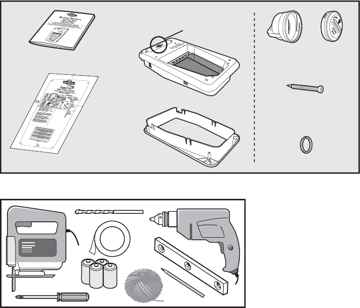
Components
Interior Frame
with Flap
Located inside the battery
compartment is the SmartKey™, RFA-67
battery, mounting screws and key ring.
Exterior Frame
Cutting Template
Operating Guide
Mounting Screws
(4 pcs. small door)
(8 pcs. large door)
Key Ring
SmartKey™Battery
(PetSafe®
RFA-67)
Tools Needed • Jigsaw or Keyhole Saw
• Electric Drill
• ⅜” (10 mm) Drill Bit
• Phillips Screwdriver
• 4 D-Cell (LR20)
Batteries (required)
• Level
• Tape
• Pencil
• String
____________________________________________________________________________________________________________________________________________
How the SmartDoor™ Works
Using radio-frequency technology, the SmartDoor™ reads a SmartKey™’s unique signal and triggers
a battery power-driven fl ap to unlock so your pets can come and go as they please. When the
SmartDoor™ no longer senses your pets’ SmartKey™, the fl ap automatically locks back into place.
The SmartDoor™ can detect up to fi ve programmed SmartKeys™ and also operates in two other
modes: fully locked mode and unlocked mode.
Install the SmartDoor™ Through a Wall with the
SmartDoor™ Conversion Kit
SmartDoor™ Conversion Kits are available for wall installation applications. The wall extension
conversion kit frames out exposed areas, giving your door installation a clean, smooth, fi nished
look. For brick, concrete or block wall construction an additional extension is available for the
large conversion kit. Note: The SmartDoor™ Conversion Kit Small is designed to be recessed into
the brick and does not require additional tunnel extensions. You may purchase a SmartDoor™
Conversion Kit or large extensions through selected online websites, www.petsafe.net or by calling
our Customer Care Center. See “Replacement Parts” on page 12.
Key Defi nitions
Radio-Frequency Technology – The use of a radio-frequency signal that can be transmitted
without wires.
SmartKey™ – A SmartKey™ is a battery-operated transmitter that sends a unique code to
the SmartDoor™.

www.petsafe.net 5
SmartDoor™ – The SmartDoor™ is an intelligent receiver using an internal antenna to pick up a
unique SmartKey™ code for selective pet entry and exit.
SmartDoor™ Flap – The SmartDoor™ fl ap is a weather resistant, plastic fl ap with UV
sun protection.
Antenna - The antenna is located inside the SmartDoor™ and receives radio signals from the
SmartKey™. The SmartKey™ must be located within a certain proximity of the antenna in order for
the unique code to be read.
Radio-frequency Interference – Radio-frequency interference is due to radio-frequency signals
from other household appliances or common electronic products that negatively affect the ability
of the SmartDoor™ to receive a signal from a SmartKey™. Radio-frequency interference or “noise”
can come from a variety of sources. Interference can be minimal, constant or ever changing based
on usage and closeness of other electronic household items during SmartDoor™’s operation. It is
recommended that household appliances and common electronic products be placed at least two
feet (60 cm) away from the SmartDoor™’s location.
Sensitivity Knob – Conveniently placed on the interior frame of the SmartDoor™ is the sensitivity
knob. You can easily adjust the SmartDoor™’s sensitivity, taking into account common interferences
and environmental factors to optimize SmartDoor™ operation.
Sensitivity Level – The level of sensitivity can be adjusted by turning the sensitivity knob
from minimum to maximum, depending on radio-frequency interference and the SmartDoor™’s
application and/or location. Pre-set from the factory, the sensitivity level should not be adjusted
until after installation. For example, the sensitivity level may need to be increased if the
SmartDoor™ is installed in a metal door. Reference page 10 for more information on how to
adjust sensitivity.
MODE-RESET Button – Easily select an Operational Mode on your SmartDoor™ by holding the
MODE-RESET button to cycle through selections of operation: LOCKED, UNLOCKED or AUTOMATIC.
LEARN Button – The LEARN button programs a SmartKey™’s unique code to be read by the
SmartDoor™. (One) SmartKey™ comes programmed and ready to use. You may program up to fi ve
SmartKeys™ (each sold separately) to one SmartDoor™.
Operational Modes
LOCKED Mode – The SmartDoor™ fl ap is locked and does not allow entry or exit for any pet.
UNLOCKED Mode – The SmartDoor™ fl ap is unlocked and allows entry and exit for all pets.
AUTOMATIC Mode – The SmartDoor™ fl ap is electronically locked and allows entry and exit for
the pet wearing a programmed SmartKey™.
Battery Compartment – The battery compartment is located on the Interior Frame and requires
(four) D-cell (LR20) batteries. Installation mounting screws, key ring, SmartKey™ and the (one)
RFA-67 battery are all located inside the battery box during shipping for your convenience.
RFA-67 Battery – The RFA-67 battery powers the SmartKey™ and is replaceable. Additional
RFA-67 batteries are available at retailers, or by calling PetSafe® Customer Care Center or visiting
www.petsafe.net. Typical life of the RFA-67 is approximately six months.
Outer Frame Size – Overall pet door dimensions
Cut-out Size – Opening cut in homeowner’s door for proper fi t and pet door installation
Replacement Flap Size – Overall fl ap size when removed from pet door
Flap Opening Size – Usable fl ap space for pet to enter and exit through the pet door
Interior Frame – Pet door frame on the inside of home
Exterior Frame – Pet door frame on the outside of home
PREPARE
Preparing Your SmartDoor™
DO NOT PROCEED WITH CUT-OUT OR INSTALLATION UNTIL ALL STEPS A-D BELOW
HAVE BEEN COMPLETED. DO NOT REMOVE SENSITIVITY STICKER UNTIL AFTER
INSTALLATION.
6 1-800-732-2677
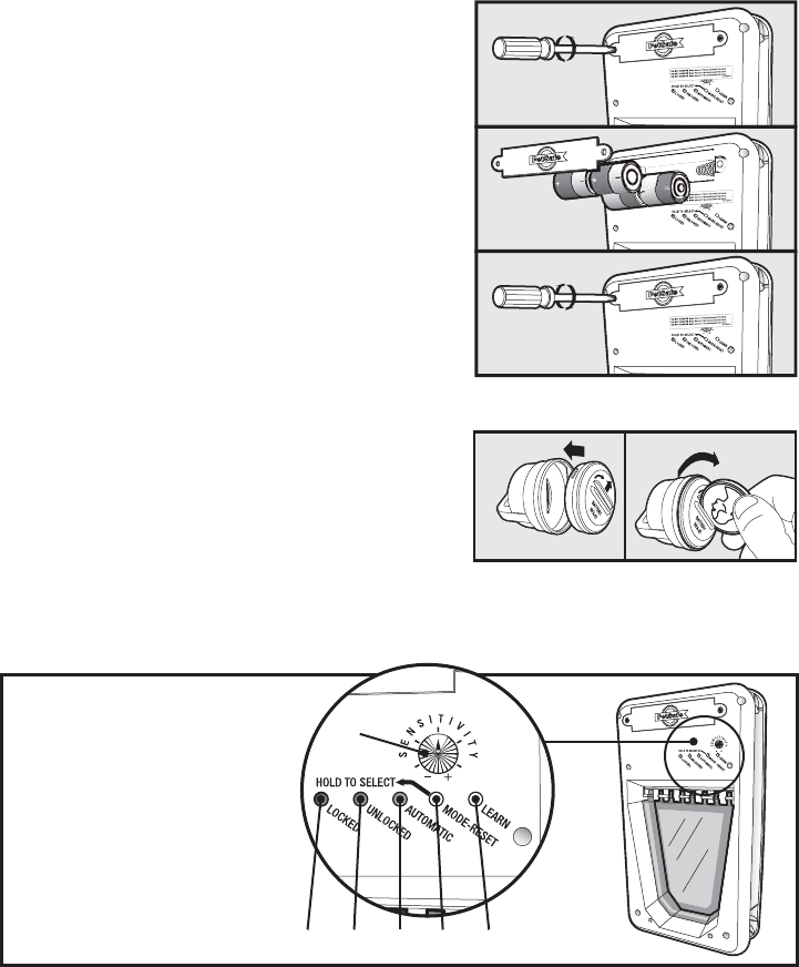
A. Place Batteries in the SmartDoor™
1. With a Phillips screwdriver, remove the two Battery
Compartment Cover screws.
2. Remove the Battery Compartment Cover.
3. Refer to the inside of the Battery Compartment
Cover for the proper orientation of the four D-Cell
(LR20) batteries.
4. Replace the Battery Compartment Cover and re-
install the two screws.
5. When the batteries are placed in the Electronic
SmartDoor™ the red light will illuminate for
two seconds and the fl ap will move into the
locked position, unless the fl ap is already in the
locked position.
NOTE:
The door must be in the upright position for
the fl ap to center properly and operate correctly.
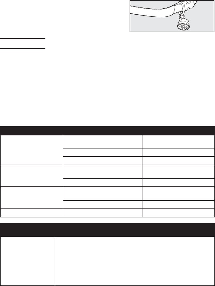
B. Place Battery in the SmartKey™
1. Place the PetSafe® RFA-67 battery into the bottom of
the SmartKey™.
2. Using a coin, rotate one-quarter turn clockwise to
secure the PetSafe® RFA-67 battery.
NOTE:
The SmartKey™ has a red light that will fl ash
when the PetSafe® RFA-67 battery is low; the battery
should be replaced as soon as possible.
C. Check Operational Modes Before Installation
Operational Indicators
Electronic SmartDoor™
A. Sensitivity Knob
B. Locked or Low
Battery Red Indicator
C. Unlocked or Learn
Mode Green Indicator
D. Automatic or Error
Mode Yellow Indicator
E. Mode-Reset
Selection Button
F. Learn Mode Button
B C D E F
A
• To check if operational settings are working properly, hold down the MODE-RESET button
until each operational mode has cycled through once to allow red, green and yellow lights to
illuminate one at a time.
Operational Modes
LOCKED MODE – Does not allow entry or exit for any pet. The SmartDoor™ ships from the
factory in LOCKED MODE and when batteries are placed in the SmartDoor™, it will enter
LOCKED MODE. To set: hold the MODE-RESET button until red light illuminates and release
when selected.
UNLOCKED MODE – Allows entry and exit for all pets. To set: hold the MODE-RESET button
until the green light illuminates and release when selected.
www.petsafe.net 7
AUTOMATIC MODE – Allows entry and exit for a pet wearing a programmed SmartKey™.
To set: hold the MODE-RESET button until the yellow light illuminates and release when
selected. Five SmartKeys™ can be programmed to one SmartDoor™ for selective entry and exit
during AUTOMATIC MODE.
NOTE:
If at any time the red light remains illuminated, replace with a set of fresh batteries. If
that does not reset the red light, please call our Customer Care Center for additional help.
If any part of step C was unsuccessful, please call our Customer Care Center for additional help.
D. Check SmartDoor™ Location Before Installation
DO NOT REMOVE SENSITIVITY STICKER BEFORE INSTALLING THE SMARTDOOR™.
Prior to installation, it is recommended to check that the SmartDoor™ will operate properly in the
intended location or application to guard against possible severe radio-frequency interference.
Household appliances and common electronic products should be located at least two feet (60 cm)
away from the SmartDoor™’s location. Radio-frequency interference detected from other household
appliances or common electronic products will negatively affect the ability of the SmartDoor™ to
receive a SmartKey™ signal. Typical appliances and products to consider are laptop computers,
wireless telephones, microwaves, televisions, garage door openers, hand-held electronic devices
(such as cell phones, game stations and remote controls).
The sticker placed over the sensitivity knob should not be removed until after installation, as the
factory default sensitivity setting is positioned at the optimal level for most installations.
It is recommended to install SmartDoor™ in a location where direct wind is not a factor. Operating
Temperature Range: -5˚ F to 180˚ F (-20.5˚ C to 82˚ C). Operating Humidity Range: 0 to 99.9%.
• To check if SmartDoor™’s radio-frequency technology will operate properly in desired location
and application, place SmartDoor™ directly in front of and against the door or application in the
upright position. After performing steps A-C, now set the SmartDoor™ in AUTOMATIC mode and
hold the SmartKey™ directly in front of the SmartDoor™. The SmartDoor™ fl ap should unlock in
about three seconds. Remember, the SmartKey™ included in the kit is already programmed to
the SmartDoor™.
NOTE:
If there are existing SmartKeys™ in the household, remove all (RFA-67)
batteries while performing step D except the SmartKey™ included with the SmartDoor™.
If the SmartDoor™ does not unlock, move the SmartDoor™ to another location and follow steps A-D
once more. If the SmartDoor™’s location test above was unsuccessful, please call our Customer
Care Center for additional help.
When steps A-D are completed and all are successful, your SmartDoor™ is ready for installation.
INSTALL
Installing Your SmartDoor™
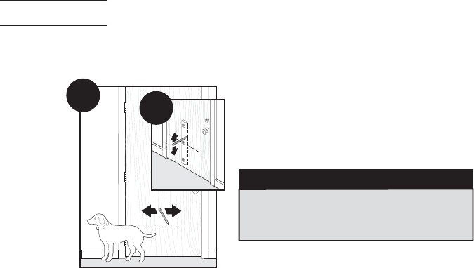
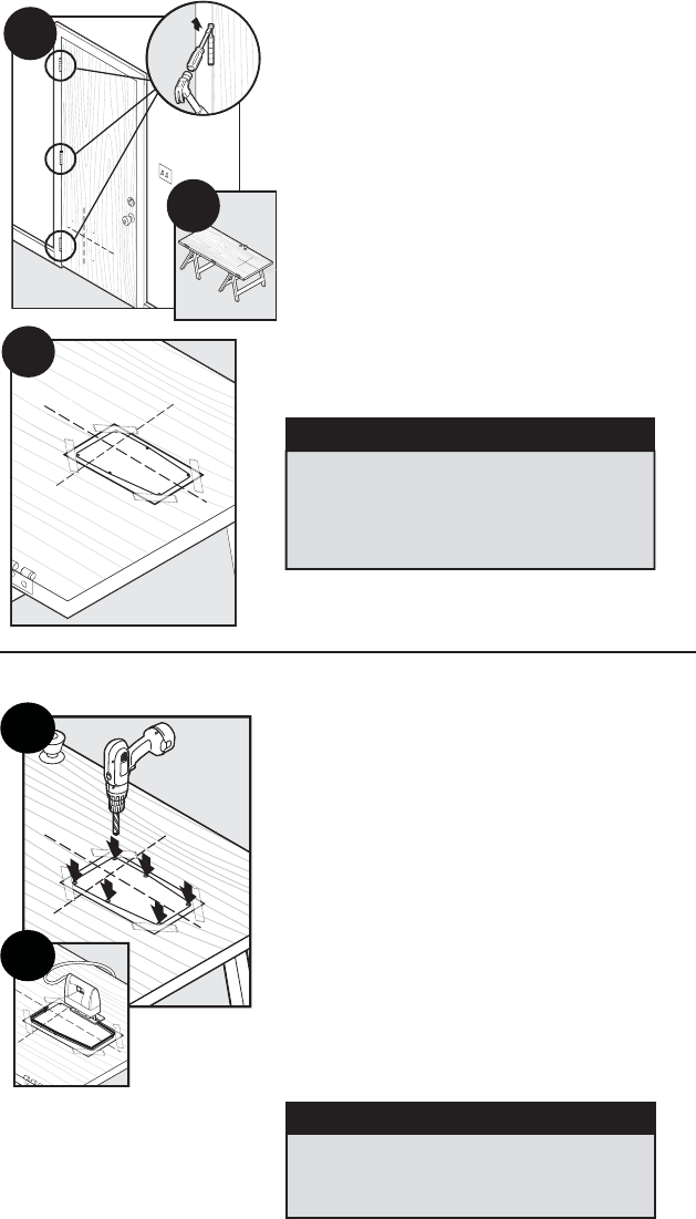
Step
1
Determine Pet Door Location
1A 1B 1A
Measure and mark your pet’s shoulder
height on the door.
1B Determine location for the pet door. Draw
a vertical center line through the shoulder
height line using a level.
NOTICE
If homeowner’s door or other application is
not level, the pet door must be marked level to
swing properly.
8 1-800-732-2677
Step
2
Preparing Door
2A
2B
2C
2A Remove door from hinges.
2B Place on a raised level surface such as
saw horses.
Helpful Tip:
Clamp or weigh down the door to
prevent it from moving.
NOTE:
The pet door can be installed with the
door hanging based on your skill level.
2C Match the marked lines on the door with the
shoulder and center lines on the template. Tape
the template in place.
NOTICE
When applying the template there should be a
minimum of 3” (7.6 cm) between the bottom
and sides of the door and the outer edge of the
template to maintain the structural integrity of
the door.
Step
3
Cut Pet Door Opening
3A
3B
3A Leave template on and drill ⅜” (10 mm) holes
in the inside corners of template. These will be
the pilot holes for the saw blade.
Helpful Tip: Use both hands to hold drill steady and
straight at a 90° angle.
3B Beginning in one of the holes you just drilled,
cut along the template lines. After cutting out the
opening, remove excess template. You may need
to recut to square the opening. This is necessary
for the pet door frame to fi t correctly.
Helpful Tip:
Use a proper saw blade according
to door material (for example a wood blade for
wood door and metal blade for a metal door).
When cutting use both hands to hold the saw
slow, steady and straight at a 90° angle. This will
prevent the blade from cutting unevenly between
interior and exterior areas of door.
NOTICE
Make sure there is nothing underneath the
door where you will be drilling the holes or
cutting out opening.
www.petsafe.net 9
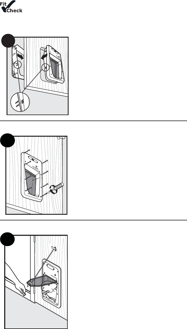
Step
4
Install Pet Door
Before putting away the jigsaw, place the interior frame (frame with the
fl ap) inside the cut out and check the fi t. Then, place the exterior frame into the
underside of the door to check the fi t. If frames do not fi t inside the opening, you
may need to recut to square opening before proceeding with installation.
4
4 Re-hang door and place interior frame with
fl ap inside cut-out of interior door. Place exterior
frame on exterior of door and press fi rmly against
interior frame and exterior frame with both hands.
Continue to press while moving hands from bottom
to top of frames until alignment tabs connect and
both frames are fi rmly in place.
Helpful Tip:
Use painters’ tape across SmartDoor™’s
interior frame and door to keep in place while
positioning the exterior frame.
Step
5
Insert Screws
5
5 Thread mounting screws through interior
frame and align with exterior frame. Tighten with
screwdriver. DO NOT OVERTIGHTEN.
Helpful Tip:
If using an electric screwdriver, set on
low torque.
NOTE:
Small SmartDoor™ has four screw
placement holes and Large SmartDoor™ has eight
screw placement holes.
Step
6
Train Your Pet
6
6 Tape the fl ap open to help your pet become
familiar with the pet door opening. When your pet
is more comfortable let the fl ap down and operate
the SmartDoor™ in UNLOCKED Mode encouraging
your pet to push through the fl ap. Once your
pet is comfortable entering and exiting through
the closed fl ap, set SmartDoor™ to AUTOMATIC
Mode and operate with your pet’s programmed
SmartKey™. Walk your pet up to the SmartDoor™
until the SmartKey™ is detected and fl ap unlocks.
Repeat training your pet to walk up to SmartDoor™
and push open fl ap to the other side.
Helpful Tip:
Try treats to encourage your pet to
push through the SmartDoor™ fl ap.
10 1-800-732-2677
NOTE:
The SmartDoor™ is designed with an electric motor to release and unlock fl ap when a
SmartKey™ is detected. Do not allow your pet to run or charge through the SmartDoor™. Due to
variable radio-frequency interferences it could take several seconds for SmartKey™’s unique code
to read properly and SmartDoor™’s fl ap to unlock.
SET
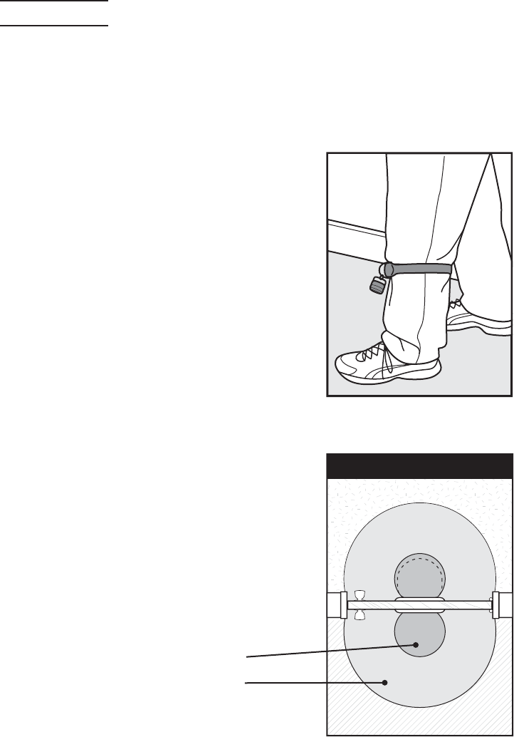
A. Setting SmartDoor™’s Sensitivity Level
It is necessary to set your SmartDoor™’s sensitivity level so your pet’s SmartKey™ works properly
due to location or application material, such as radio-frequency interferences, wood or metal
door installations.
To begin, it is recommended to use the split ring (included) to attach the SmartKey™ to the D-ring
on your pet’s collar. Also do not use metal tags as the additional metal can cause radio-frequency
interference and hinder the detection of your pet’s SmartKey™. Now, continue with the following
“product in use” steps:
1. Put the dog’s collar on your leg just below your knee. Tape
may be used to secure the collar, if necessary. See A.
2.
Stand directly in front of the SmartDoor™ so the SmartKey™
is approximately 2.5 feet (76 cm) from the SmartDoor™.
3. Put the SmartDoor™ in the UNLOCKED Mode. (See page 6
for operational instructions).
4. Put the SmartDoor™ in the Sensitivity Test Mode by
holding down the MODE-RESET and LEARN buttons at the
same time until all three lights fl ash once.
5. Turn the Sensitivity Knob counter clockwise to the
minimum position, then turn the Sensitivity Knob
clockwise until all lights begin to fl ash again.
6. Slowly continue to adjust the Sensitivity Knob clockwise
until you see a minimum of six consecutive fl ashes and
stop adjusting. Do not adjust higher than necessary.
7. Put the SmartDoor™ in AUTOMATIC Mode and step away
at least 10 feet (3 m), allowing the door to automatically
lock. This may take up to fi fteen seconds after the
SmartKey™ no longer is detected.
8. Now confi rm the sensitivity level by approaching the
SmartDoor™ again. The door should unlock when you
step within approximately 2 feet (60 cm) in front of the
SmartDoor™.
A.
B. Understanding Sensitivity and the
Active Area
The Active Area is the area where the SmartDoor™ will
consistently open based on your adjustment of the
sensitivity level. In the Fringe Area the SmartDoor™ may
open inconsistently due to variables of radio-frequency
interferences or refl ections. In the Inactive Area the door
will generally not unlock automatically. See B.
You may see slight differences between Outside and Inside
Active Areas due to radio-frequency interferences.
Depending on location
and application
~ 2.5 feet (76 cm)
~ 6 feet (183 cm)
Inactive
Inactive
Outside
Inside
Fringe
Active
Active
Fringe
Door - Top View
B.
www.petsafe.net 11
C. Programming a New SmartKey™
To reduce error while programming, remove the RFA-67 battery from all programmed SmartKeys™
except the one you are programming. Press and hold the LEARN button until the green light
illuminates and begins to fl ash, now release the button. Bring the SmartKey™ directly below the
green light and the light will stop fl ashing and illuminate for two seconds. Now your new SmartKey™
has been programmed and added to memory. Up to fi ve different SmartKeys™ can be added, one at
a time.
D. Attach the SmartKey™ to the Pet’s Collar
A split key ring has been provided to attach to your pet’s
collar and should hang under the pet’s neck.
The SmartDoor™ includes (one) SmartKey™ which comes
pre-programmed and ready to use.
OPERATE
Operating Your SmartDoor™
LOCKED MODE – Does not allow entry or exit for any pet. The SmartDoor™ ships from the factory
in LOCKED MODE and when batteries are placed in the SmartDoor™, it will enter LOCKED MODE. To
set: hold the MODE-RESET button until the red light illuminates and release when selected.
UNLOCKED MODE – Allows entry and exit for all pets. To set: hold the MODE-RESET button until
the green light illuminates and release when selected.
AUTOMATIC MODE – Allows entry and exit for a pet wearing a programmed SmartKey™; up
to fi ve SmartKeys™ can be programmed into one SmartDoor™ for selective entry and exit during
automatic mode. To set: hold the MODE-RESET button until the yellow light illuminates and
release when selected.
NOTE:
If at any time the red light remains illuminated, replace with a set of fresh batteries. If that
does not reset the red light, please call our Customer Care Center for additional help.
Illuminating Color Condition Pet Door Status
RED
Solid only for two seconds after
selecting LOCKED Mode LOCKED Mode
Flashing Low battery alert
Constant solid Internal failure has occurred
GREEN
Solid only for two seconds after
selecting UNLOCKED Mode UNLOCKED Mode
Flashing Learn Mode
YELLOW
Solid only for two seconds after
selecting AUTOMATIC Mode AUTOMATIC Mode
Flashing Error alert
RED, GREEN AND YELLOW Flashing at the same time Sensitivity Test Mode
Troubleshooting
SmartDoor™ does
not respond to the
presence of the
SmartKey™ when my
pet is directly in front
of the SmartDoor™
within three seconds
• Check that the SmartDoor™ is in AUTOMATIC Mode.
• Check that the SmartKey™ has been programmed to the SmartDoor™.
• Check sensitivity level has been properly set, see page 10.
• Check that the RFA-67 battery in the SmartKey™ is screwed in tightly.
• Check that the batteries in the SmartDoor™ are fresh.
• If the condition persists, check that there are no radio-frequency
transmitting devices or electronic devices that radiate electrical
energy, which may interfere with the operation of the SmartDoor™.

12 1-800-732-2677
Yellow light is fl ashing • Obstruction to the flap has been detected.
• Press the MODE-RESET button to cause the SmartDoor™ to attempt
to lock the flap. Clear any obstructions that keep the flap from
locking. When the flap successfully locks, normal operation is resumed.
• If your large SmartDoor™ does not close properly, you can purchase
an additional magnet kit to help center flap due to constant wind
or a variance between indoor and outdoor pressure. Please call the
Customer Care Center for further assistance.
Red light remains
illuminated (internal
failure has occurred)
• Remove batteries and replace them with a fresh set of batteries. If
that does not reset the red light, please call Customer Care Center at
1-800-732-2677 for additional help.
Red light is fl ashing • Low battery indicator, replace batteries.
Red, green and yellow
lights are fl ashing • Sensitivity set mode has been activated. It will automatically
de-activate in thirty minutes, or can be immediately de-activated by
pressing the MODE-RESET button once.
Revert SmartKey™ to Default Factory Setting
The SmartDoor™ can be cleared of all additional programmed SmartKey™ EXCEPT the one included
from the factory. To do this, fi rst take out batteries from battery compartment. Then, as you place
batteries back into the battery compartment, hold down the LEARN button. When LEARN button
is held and the last battery is in place, the red and green lights will illuminate three times. Now,
all SmartKeys™ programmed to the SmartDoor™ have been cleared except the one SmartKey™
included with your SmartDoor™.
Clear SmartKey™ Memory
The SmartDoor™ can be cleared of all programmed SmartKeys™, even the one included from the
factory. To do this, fi rst remove batteries from battery compartment. Then, as you place batter-
ies back into the battery compartment, hold down the MODE-RESET button. When MODE-RESET
button is held and the last battery is in place, the red and yellow lights will illuminate three times.
Now all SmartKeys™ have been cleared.
______________________________________________________________________________
Replacement Parts and Accessories
To purchase replacement parts for your PetSafe® SmartDoor™, contact the Customer Care Center
at 1-800-732-2677 or visit our website at www.petsafe.net to locate a retailer near you.
Customer Care International
Canada: 1-800-732-2677
United Kingdom: 0800 046 1414
Europe: 00 800 18 18 20 20
Australia: 1800 786 608
New Zealand: 0800 543 054
Component Part Number
SmartKey™PAC11-11405
PetSafe® RFA-67 Battery RFA-67
Small Replacement Flap CPA11-11580/MPA00-12830
Large Replacement Flap CPA11-11579/MPA00-12829
Small SmartDoor™ Hardware Kit CPA00-11617/MPA00-12814
Large SmartDoor™ Hardware Kit CPA00-11618/MPA00-12815
Small Wall Conversion Kit MPA11-12019
Large Wall Conversion Kit MPA11-12020
Large Extension Tunnel CPA00-12021/MPA00-12820
Small Wall Conversion – Hardware Replacement Kit CPA00-12054/MPA00-12821
Large Wall Conversion – Hardware Replacement Kit CPA00-12055/MPA00-12822

www.petsafe.net 13
This product has the benefi t of a limited manufacturer’s warranty. Details of the warranty
applicable to this product and its terms can be found at www.petsafe.net and/or are available by
sending a stamped addressed envelope to PetSafe® Ltd. Redthorn House, Unit 9, Chorley West
Business Park, Ackhurst Road, Chorley, Lancashire PR7 1NL, United Kingdom.
______________________________________________________________________________
Terms of Use and Limitation of Liability
1. Terms of Use
This Product is offered to you conditioned upon your acceptance without modification of the
terms, conditions and notices contained herein. Usage of this Product implies acceptance of all
such terms, conditions, and notices.
2. Proper Use
This Product is designed for use with pets where training is desired. The specific temperament
of your pet may not work with this Product. If you are unsure whether this is appropriate for
your pet, please consult your veterinarian or certified trainer. Proper use includes reviewing
the entire Operating Guide provided with your Product and any specific Caution statements.
3. No Unlawful or Prohibited Use
This Product is designed for use with pets only. This pet training device is not intended to
harm, injure, or provoke. Using this Product in a way that is not intended could result in
violation of Federal, State or local laws.
4. Limitation of Liability
In no event shall Radio Systems® Corporation be liable for any direct, indirect, punitive,
incidental, special or consequential damages, or any damages whatsoever arising out of or
connected with the use or misuse of this Product. Buyer assumes all risks and liability from
the use of this Product.
5. Modification of Terms and Conditions
Radio Systems Corporation reserves the right to change the terms, conditions and notices
under which this Product is offered.
Perchlorate Battery
Perchlorate Material – special handling may apply. See www.dtsc.ca.gov/hazardouswaste/
perchlorate.
Important Recycling Advice
Please respect the Waste Electrical and Electronic Equipment regulations in your country. This
equipment must be recycled. If you no longer require this equipment, do not place it in the normal
municipal waste system. Please return it to where it was purchased in
order that it can be
placed in our recycling system. If this is not possible, please contact the Customer Care
Center for further information.
Battery Disposal
Separate collection of spent batteries is required in many regions; check the regulations in your area
before discarding spent batteries.
SmartDoor™:
This device operates on four Alkaline batteries of the type LR20/D-cell with a 1.5 Volt, 18,000 mAH
capacity. Replace only with the equivalent batteries.
SmartKey™:
This device operates on two Lithium batteries of the type CR2032 with a 3 Volt, 220 mAH capacity.
Replace only with equivalent battery available from the Customer Care Center.
Please see page 6 for instructions on how to remove the batteries from these products for
separate disposal.
______________________________________________________________________________
Compliance
FCC/Canada
This Class B digital apparatus complies with Canadian ICES-003. This equipment has been tested
and found to comply with the limits for a Class B digital device, pursuant to Part 15 of the FCC
Rules. These limits are designed to provide reasonable protection against harmful interference
when the equipment is operated in a residential environment. This equipment generates, uses,
and can radiate radio frequency energy and, if not installed and used in accordance with the

14 1-800-732-2677
instruction guide, may cause harmful interference to radio communications. However, there is
no guarantee that interference will not occur in a practical installation. If this equipment causes
harmful interference to radio or television reception, which can be determined by turning the
equipment off and on, the user is encouraged to try to correct the interference by one or more of
the following measures:
• Relocate the interfered receiving antenna.
• Increase the separation between the equipment and receiver.
• Connect the equipment into an outlet on a circuit different to that to which the receiver
is connected.
• Contact the Customer Care Center.
This device complies with Industry Canada Rules. This device complies with part 15 of the FCC
Rules. Operation is subject to the following two conditions: (1) This device may not cause harmful
interference, and (2) this device must accept any interference received, including interference that
may cause undesired operation.
Unauthorized changes or modifi cations to the equipment, not approved by Radio Systems®
Corporation, could result in not meeting compliance with FCC regulations and could void the user’s
authority to operate the equipment.
This equipment has been tested and found to comply with relevant EU Electromagnetic
Compatibility, Low Voltage and R&TTE Directives. Before using this equipment outside the EU
countries, check with the relevant local R&TTE authority. Unauthorized changes or modifi cations to
the equipment that are not approved by Radio Systems® Corporation are in violation of EU R&TTE
regulations, could void the user’s authority to operate the equipment, and void the warranty.
The Declaration of Conformity can be found at: http://www.petsafe.net/customercare/eu_docs.php.
Australia
This device complies with the applicable EMC requirements specifi ed by the ACMA (Australian
Communications and Media Authority).