Radio Thermostat of America 6021Z Thermostat (2.4GHz Transceiver) User Manual 711 002 IBIE 6021z Install guide 1nov07 ai
Radio Thermostat Company of America, Inc Thermostat (2.4GHz Transceiver) 711 002 IBIE 6021z Install guide 1nov07 ai
User Manual
• Your thermostat is a precise instrument, take care.
• Turn off electricity to the appliance before installing or
servicing thermostat or any part of the system.
• Do not turn electricity back on until work is completed.
• Do not short (jumper) across electric terminals at control on
furnace or air conditioner to test the system. This will damage
the thermostat or Wall Unit and void your warranty.
• All wiring must conform to local codes and ordinances.
• This Thermostat/Wall Unit is designed for use with 24 volt AC
and millivolt systems. The Wall Unit should be limited to a
maximum of 1.0 amps; higher amperage may cause damage
to the Wall Unit.
Caution
Front Cover
Back Cover
2nov07draft2
28oct07initialrel
1711-002
Install guide 6021z
Customer Support: 877-505-2353 or
Visit our website www.ritetemp-thermostats.com
Printed in China
Installation 8082
RESET
MENU PROGRAM
Front cover
pg 1
pg 2
Instruction Book Concept
First page
spread
C A U T I O N
Your thermostat is a precise instrument.
Please handle it with care.
Turn off electricity to the appliance before installing or
servicing thermostat or any part of the system. Do not
turn electricity back on until work is completed.
Do not short (jumper) across electric terminals at
control on furnace or air conditioner to test the system.
This will damage the thermostat and void your warranty.
All wiring must conform to local codes and ordinances.
This thermostat is designed for use with 24 volt AC and
millivolt systems. The thermostat should be limited to a
maximum of 1.0 amps; higher amperage may cause
damage to the thermostat.
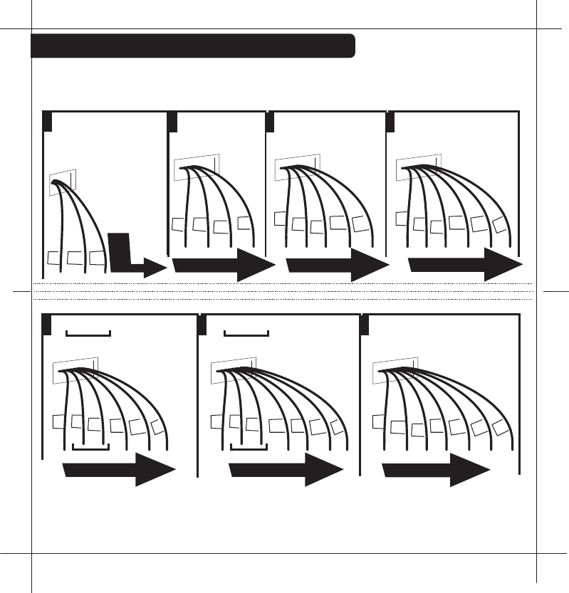
On replacement installations, mount the new thermostat in place of the
old one if possible.
On new Installations, follow the guidelines listed below.
Locate the thermostat on an inside wall, about 5 ft. (1.5m) above the
floor, and in a room that is used often.
Do not install it where there are unusual heating conditions, such as: in
direct sunlight; near a lamp, radio, television, radiator register, or
fireplace; near hot water pipes in a wall; near a stove on the other side
of a wall.
Good
5ft.
(1.5m)
PG
2
Installation 8082
1 Location
Caution
Tools
To avoid electrical shock and to prevent damage to the furnace, air conditioner,
and thermostat, disconnect the power supply before beginning work.
This can be done at the circuit breaker, or at the appliance.
On replacement installations, mount the new thermostat in place of the
old one if possible.
On new Installations, follow the guidelines listed below.
Locate the thermostat on an inside wall, about 5 ft. (1.5m) above the
floor, and in a room that is used often.
Do not install it where there are unusual heating conditions, such as: in
direct sunlight; near a lamp, radio, television, radiator register, or
fireplace; near hot water pipes in a wall; near a stove on the other side
You will need #1 Phillips screwdriver (small) and
Drill with 3/16-in. (4.8mm) bit for this installation.
ENGLISH
HEATCOOL2STGFAN
BINDINGLOW
BATT
HEAT
HEAT
COOL
OFF
FAN
AUTO
ON
NORMAL
SAVE
ENERGY
HEATCOOL2STGFAN
BINDINGLOW
BATT
HEAT
HEAT
COOL
OFF
FAN
AUTO
ON
NORMAL
SAVE
ENERGY
Product Name: 6021z
Document Title: Install Guide ENG
Document Type Code: IBIE
Part Number: 711-002
InstallWallUnit
Caution
Tools
Toavoidelectricalshockandtopreventdamagetothefurnace,airconditioner,
andthermostatwallunit,disconnectthepowersupplybeforebeginningwork.
Thiscanbedoneatthecircuitbreaker,orattheappliance.
The6021zWirelessThermostatsystemis
madeoftwoparts-TheThermostatand
theWallUnit.YouwillfirstinstalltheWall
UnitandthenconfiguretheThermostat.
Replacementinstallations-YoucanmounttheWallUnitinplaceoftheold
thermostat.Rememberthe"C"powerwireisrequiredforoperationthis
supplies24VACtothetransmitterintheWallUnitandallowscontinuous
communicationwiththeThermostat.Becausethe6021zsystemiswirelessit
iseasiesttomounttheWallUnitnexttotheHVACunitinthebasementatticor
HVACcloseteveninareplacementinstallation.
NewInstallationorChangeoflocationfromWalltoHVAC
WerecommendtheWALLUNITunitbeinstalledinthesameareaandcloseto
theHVAClocationsoitcanbewireddirectlytotheHVAC'sthermostat
terminals.TheWALLUNITunithasnotemperaturesensingdevicesbutstill
shouldnotbemountedoutsideorwhereitwouldbeexposedtoweather
conditions.Itcanbemountedatanyangleonthewall.
24VACPower-TheWallUnitREQUIREStheHVAC24VACpowerwire(C)to
work.IftheCwireisnotavailableatapreviouswallinstallation,theCwire
mustbeaddedortheWallUnitshouldbemountedattheHVAClocation
wheretheCwirepowerisalwaysavailable.
YouwillneedasmallPhillipsscrewdriverandpossiblyadrill
with3/16-in.(4.8mm)bitformountingtheWallUnit.
PG 1
fold and
staple
PG 2
Install guide 6021z
HEATCOOL2STGFAN
BINDINGLOW
BATT
Removeoldunit
Preparewires
IMPORTANT:LABELALLWIRES
BEFOREDISCONNECTINGTHEM!
IfyouaregoingtoplacetheWallUnitinthe
samelocationastheoldthermostats...
ïSwitchelectricitytothefurnaceandair
conditionerOFF;thenproceedwiththefollowing
steps.
ïRemovecoverfromoldthermostat.Mostare
snap-ontypesandsimplypulloff.Somehavelockingscrews
onthesideorfront.Thesemustbeloosened.Notethelettersprinted
neartheterminals.Attachlabels(enclosed)toeachwirefor
identification.
ïLabelthewiresoneatatime.Youmustlabelallthewiresbeforeyou
proceed.Withallwireslabeled,removethemfromtheoldunit.
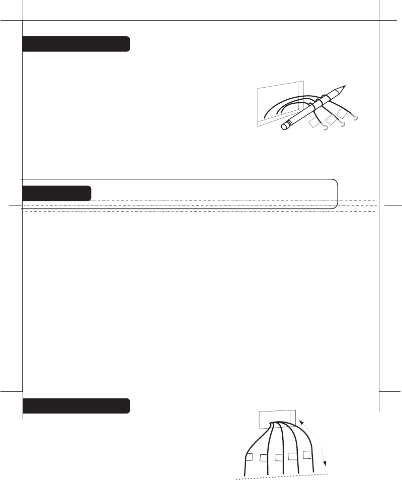
ïMakesurethewiresdonotfallbackinsidethewall.Youcanwindthem
aroundapenciltokeepthemfromfalling.
ïLoosenallscrewsontheoldthermostatandremoveitfromthewall.
ïFillwallopeningwithnon-combustibleinsulationtopreventdrafts.
IfyouaregoingtolocatetheWallUnitattheHVAC...
ïSwitchelectricitytothefurnaceandairconditionerOFF;thenproceed
withthefollowingsteps.
ïOpentheservicecoverofyourHVACsystemandlocatethethermostat
terminals.
ïRemoveanyexistingwireandrunnewthermostatwiretoaconvenient
locationforthe6021zWallUnit.
ïNotewhatcolorisconnectedtowhatterminaloftheHVACsystem.
PG
3
PG
4
B
G
W
Caution
Readinstructionscarefullybeforeremovinganywiringfromexistingthermostat.
Wiresmustbelabeledbeforetheyareremoved.THEREISNOSTANDARD
COLORCODE.Whenremovingwiresfromtheirterminals,ignorethecolorof
thewiressincethesemaynotcomplywithanystandard.
ïYouwillneedatleast2.6"ofwireforeach
ofyourconnectionstotheWallUnit.
ïIfyoudonothaveenoughwire,splice
additionalwiretoallowenoughslack.
ïFanoutwiresbelowtheholeasshown.
From Wall
G
CYRH
W
Trim
2.6"
BeforeyouConnectWires
Caution Donotallowwirestotoucheachotherorpartsonthermostat.
Pleasefollowtheseguidelinesforsafeandsecure
wireconnections.
ïEasyTerminalsdonotrequirestrippingthewire.
ïClipanybarewirefrompreviousinstallation.
ïTakecarenottodamagethelabelsforeachwireinhandling.
ïFanwiresoutasillustratedwithWallUnitbelowthewallopening.
ïWireswilldressbehindtheWallUnitandupovertheterminalarea.
ïUsetheStep-By-Stepdiagramasyourguide.
ïDonotbunchwiresbehindWallUnit.Feedslackbackintothewall
opening.
ïInsertthewireintheterminalandtighten
thescrewsecurely.
ïYouwillneedtosetConfiguration
JumperspertheStep-By-Step
diagram.Aneedle-nosepliermaybe
requiredtomodifyjumperpositions
PG
5
PG
6
Determinewhichstep-by-stepwiring
diagrambelowyoushoulduse.Make
sureyourwiresarelabeled.Thismay
requireyoutofindthe'otherend'connectionforeachwireonyourheatingor
airconditioningequipmentandreadthelabelthere.
TheWallunitmusthavethe24VACtooperate.ThisisavailableastheC
wireattheHVACora24VACadaptercanbeusedconnectedtotheRHand
theCterminal.
Whatwiresdoyouhave?
G
CYRH
W
RESET
C B O
W2
W1
Y1
Y2
RH
RC
G A
RESET
C B O
W2
W1
Y1
Y2
RH
RC
G A
HEATCOOL2STGFAN
BINDINGLOW
BATT
ïIf you combination of wires is not above you can use the wiring table
on pages 24-25 to determine your connections, or call our USA
support line at 1-877-505-2353 for help.
ïFindthereferencepagewithyourwiringdiagramandjumperset-up
information.Remember,theCwireor24vdcpowerisrequiredfortheWallUnit.
Find the set-up diagram for your system
PG
7
PG
8
Go To Page 22Go To Page 21Go To Page 20
Go To Page 18
Go To Page 23
G
RH
C W2 W Y Y2 RH G
2 stage Cool
2 stage Heat
From
Furnace
Y
2
CWY
W2
G
C W Y RH RC G
5 Wire
Heat/Cool
From
Furnace
RC
CYRH
W
C W Y RH G
4 Wire
Heat/Cool
From
Furnace
G
CYRH
W
C W RH G
3 Wire
Heat
From
Furnace
CRH G
W
From
Furnace
CW
RH
C W RH
2 Wire
Heat
Go To Page 24
C B or O W2 Y RH G
5 Wire
Heat Pump
w/ Aux Heat
From
Furnace
RH
CO
or
W2
B
G
Y
G
C B or O Y RH G
4 Wire Heat Pump
w/o Aux Heat
From
Furnace
RH
CO
or
Y
B
Go
To
PAGE 19
WIRES
WIRES
WIRES
WIRES
WIRES
WIRES
WIRES
PG 9
PG 10
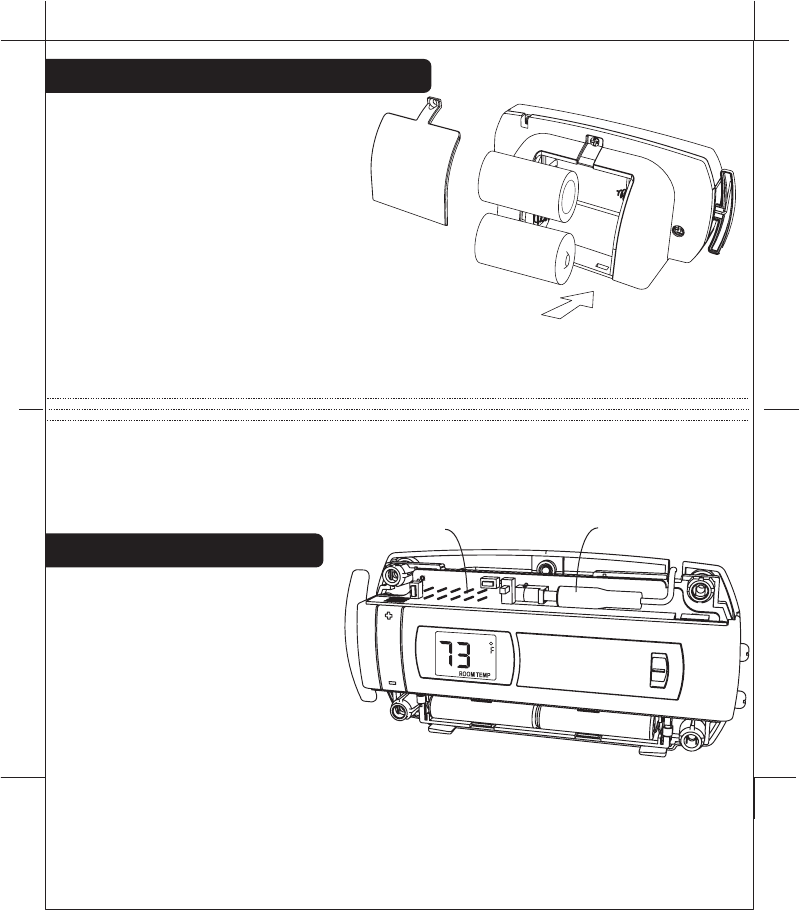
Install AAA Batteries in unit
ï
The Wall Unit requires 2 AAA batteries for power loss backup.
ï
Install 2 AAA alkaline batteries according to the polarity noted in
the compartment. The Green LED will blink.
ï
Press the RESET button to clear transient program memory. The
green LED will Blink briefly.
NOTE: Replace the batteries when the red LOW battery
indicator blinks or once a year.
ï
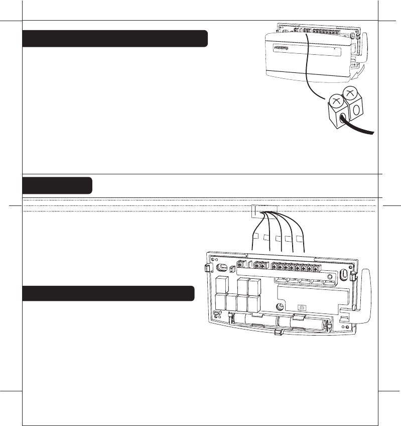
Replace cover on Wall unit.
Wall
Wires
Wall
Unit
Wall anchor
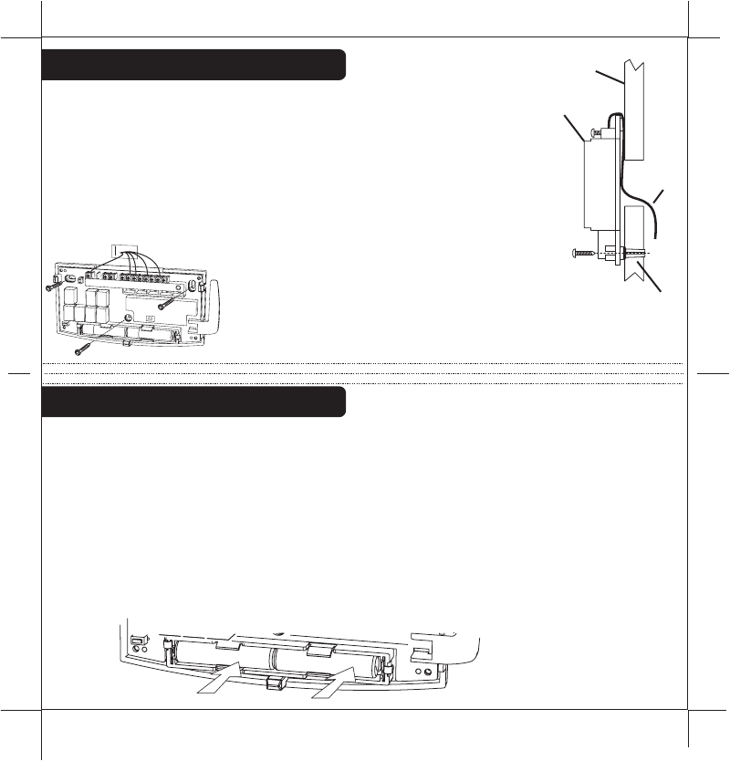
ïHoldtheWallunitagainstthewall,withthewirescoming
overthetopaboveterminalblock.Theunitwillcoverthe
holeinthewall.
ïPositionWallunitforbestappearance.Usetheoptional
stand-offsifmorespaceforwiresisneededbehind.
ïAttachtheunittothewallwiththescrewsprovided.
ïIfyouaremountingtheunittosheetrockorifyouareusing
theoldmountingholes,usetheplasticanchorsprovided.Drill
a3/16-in.(4.8mm)holefortheinsertat
eachscrewlocation,thenmountthe
base.
Mount the Wall Unit
RESET
BINDING
C B O
W2
W1
Y1
Y2
RH
RC
G A
AAA
+-
AAA
+
-
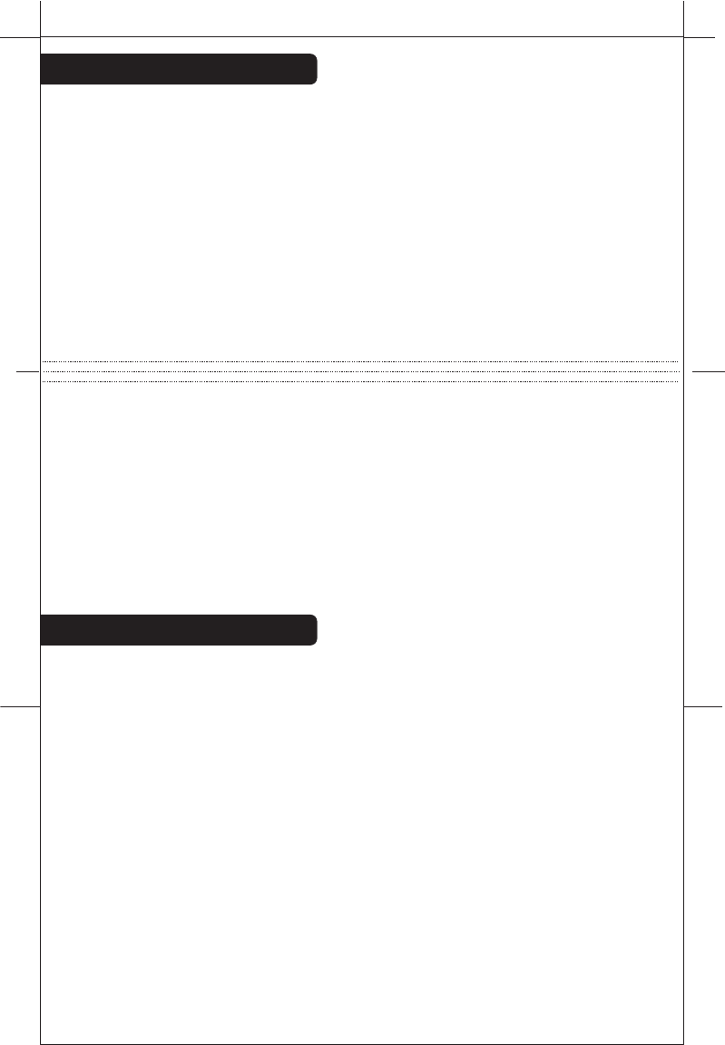
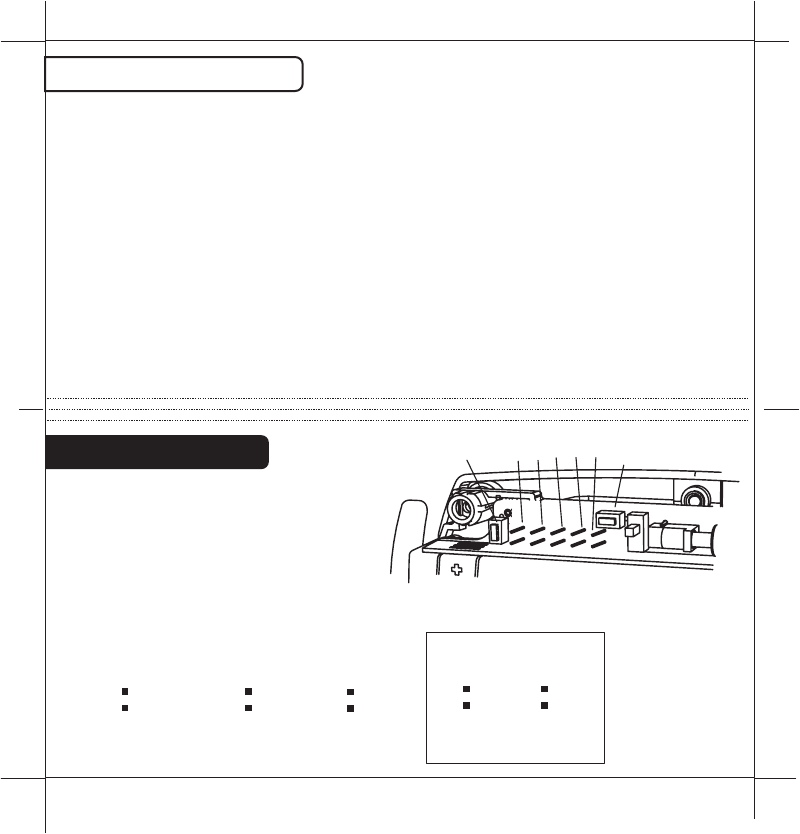
Install batteries in the Thermostat
Set Thermostat Jumpers
ïRemove the screw on the back
cover and install 2 Alkaline C cell
batteries according to noted
polarity. Replace back cover.
ïRemove the bottom front cover and
install 2 AAA Alkaline batteries according to
noted polarity. Replace bottom front cover.
NOTE: The batteries will last over 1 year and should be replaced when the
battery icon comes on, first the AAA batteries and then the C batteries.
The Thermostat can also run on the provided 6VDC plug-in adapter. It plugs
into the Thermostat under the top cover.
NOTE: The Thermostat can be wall mounted by removing the "C" battery
stand, the 6VDC power adapter is required for operation.
ïRemove top cover to
configure the Thermostat.
Refer to the step-by-step
wiring diagram you used to
wire the Wall Unit. There you
will find a jumper setting
diagram for the Thermostat unit
(pages 18 through page 24).
Push RESET on the Thermostat (anytime set up jumpers are
changed, reset is required)
PG
11
PG
12
6VDC adapter
Jumpers
C
C
AAA AAA
+
+
+
+
-
-
-
-
HEAT
NORMAL
SAVE
ENERGY
Make Wireless Connection
PG
13
PG
14
After you have finished the wiring of the WALL UNIT unit and the set the
JUMPERs of the Thermostat, the two units must be radio connected
before they can be used. If the BINDING LED at the WALL UNIT unit is on
solid, they are connected; if it is NOT ON follow this procedure connect
them.
On the WALL UNIT
Push and Hold the binding button
Touch the reset button once
When the binding LED is on solid, release the binding button
On the 6021Z THERMOSTAT
Push and Hold the binding button
Touch the reset button once
When the TEMPERATURE comes on screen, release the binding button
The above procedures clears the two radios so they can now be
connected by doing the following:
Push the Wall Unit's BINDING button once.
Push the Thermostat's BINDING button once; watch the displayed
countdown and wait! The two units are radio connected when the B units
BINDING LED is on solid.
The ZigBee radio system
There have been many radio controlled thermostat systems but they were
one way and there was no indication if they were working. The new
ZigBee radio is two way, it sends the command and gets back confirmation
that the command was received and implemented.
There is a radio tower icon on the Thermostat lower right display. If this
icon is not there, communication has been lost. If this occurs, all HVAC
functions are shut off.
Though the units are designed to work at least 100 feet from each other
that distance can be affected by interference or blocking from walls etc. If
your Thermostat unit cannot stay in communication (the radio tower icon
does not stay on) you may need a repeater unit between the two which
can be purchased at home depot.
The radio tower icon also shows a radiation pattern every time the
Thermostat communicates with the WALL UNIT unit.
NOTE: If you have labeled your wires, follow the correct Step-By-Step, and
these Check procedures do not operate your system call support at
1-877-505-2353
Check the system
Once the two units are connected, follow these procedures to verify you
have correctly installed the Thermostat and its WALL UNIT unit.
Because of the radio communication
confirmation system, there will be a
small delay between the operation
and the function. Follow these
procedures to verify you have
correctly installed the 6021z system.
To check Fan: (If you connected the
G wire - fan relay)
ïSwitch the FAN switch to the ON
position. You should see the FAN light go ON on the Wall Unit and verify that
air is blowing from the system.
Return to AUTO position for normal operation.
To check HEAT mode:
Set the mode switch to HEAT.
Set the fan switch to AUTO.
ïUsing the TEMP + button raise the Target Temp to 90deg.
Allow the system 2 min to respond.
ïVerify that heat is blowing from the system. HEAT light on the Wall Unit
should go ON.
To check COOL mode:
ïSet the mode switch to COOL.
ïPress the TEMP - button to a temp 5 degrees below the room temp.
Allow the system 2 minutes to respond.
ïVerify that cool air is blowing from the system. COOL light on the Wall Unit
should go ON.
Congratulations, you have successfully installed your unit.
Please proceed to the OPERATING Guide to initialize the
6021z System.
PG
15
PG
16
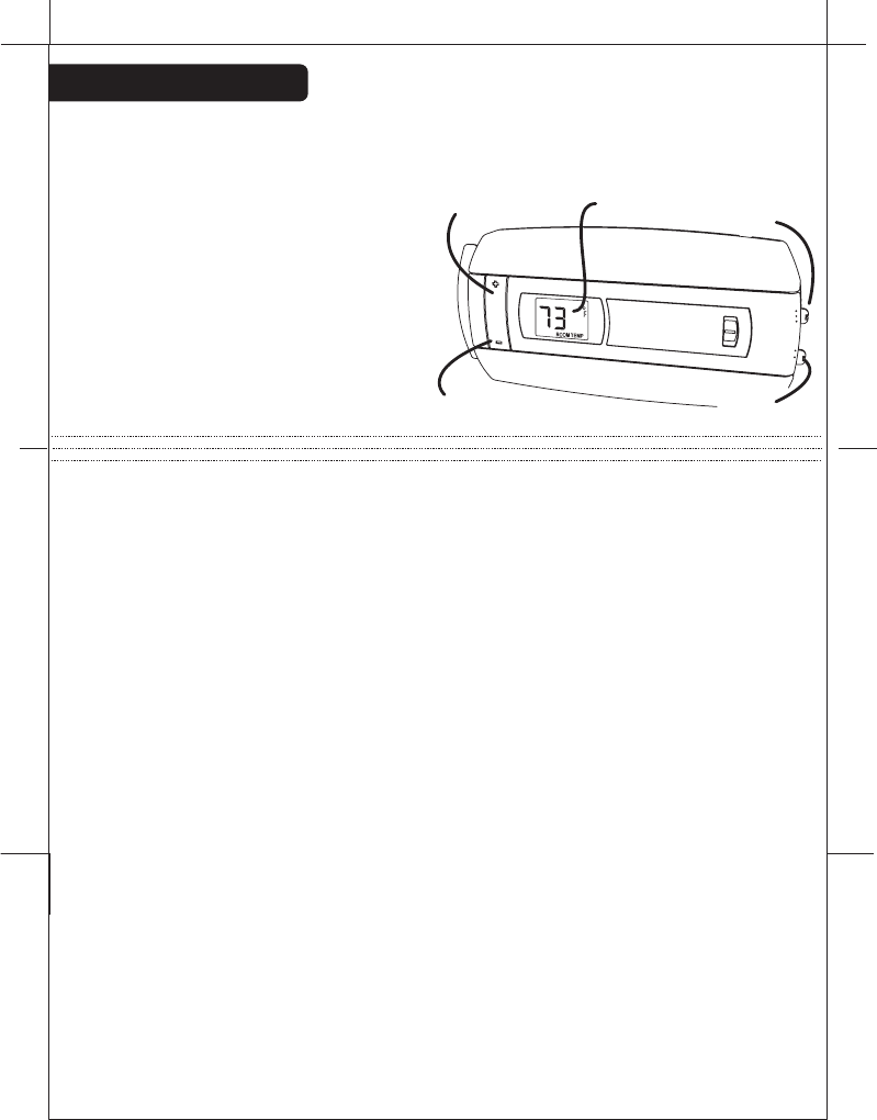
TEMP
UP button
TEMP
DOWN button
Temperature
Display Mode
Switch
Fan
Switch
HEAT
HEAT
NORMAL
SAVE
ENERGY
COOL
OFF
FAN
AUTO
ON
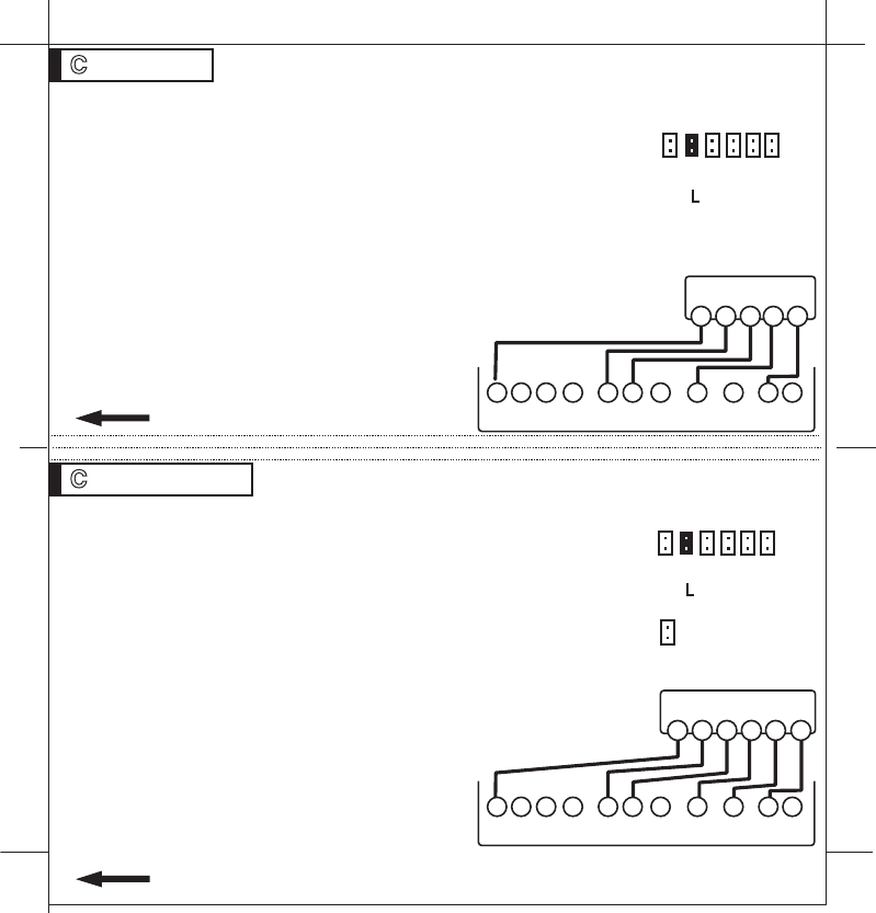
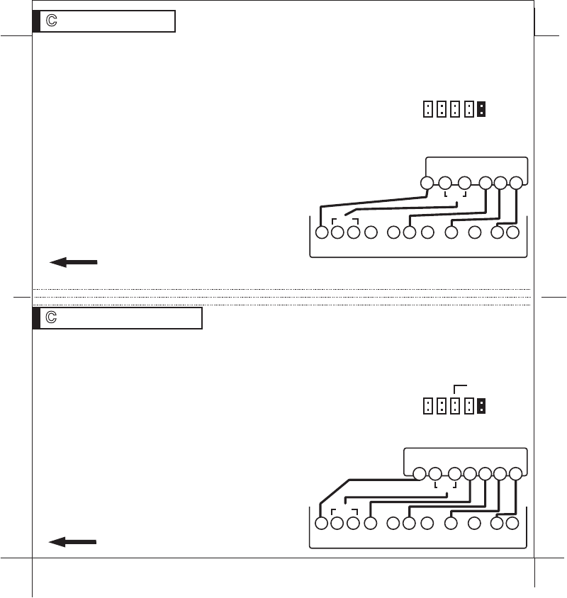
STEP 1 - Connect the W wire to the W terminal and W2 to
W2 on the Wall Unit. This connects 2 stages of heat.
STEP 2 - Connect the Y wire to the Y terminal and Y2 wire
to Y2 on the Wall Unit. This connects 2 stages of cool.
STEP 3 - Connect the RH or R wire to the RH terminal on
the thermostat. This connects the Heater/Cooler Power.
STEP 4 - Connect the G wire to the G terminal on the
Thermostat. This connects to the Fan.
STEP 5 -C wire to the C on the Wall Unit for 24vac power.
STEP 6 - Set Config jumpers per this diagram. If you
have Electric heat remove 5.
Your HVAC system is now connected
to the Wall Unit.
Please Go To Page 9
PG
18
PG
17
NOTE:The Thermostat comes from the factory calibrated to +/- 1o of actual
temperature. It is an accurate instrument. If you want your thermostat to
display the same temperature as another thermometer in your home, you
can adjust its calibration.
To change the calibration:
Remove the top cover.
Locate the calibration switch and slide it to the ON
position. The current calibration factor (+/-) of the
Thermostat will appear in the LCD display.
Push the UP or DOWN arrows until the desired
calibration factor is reached.
Slide the Calibration switch to the OFF position. The
new calibrated temperature will be displayed on the LCD.
Calibration
W2 W Y Y2 RH RC G 2 Stage Heat and Cool
Wall Unit
Terminals
Y2
W2
W Y
RH
RC G
C
HVAC SYSTEM
C B O W2 W Y Y2 RH RC G A
WIRES
Calibrate
switch
remove if
elect heat
6 5 4 3 2
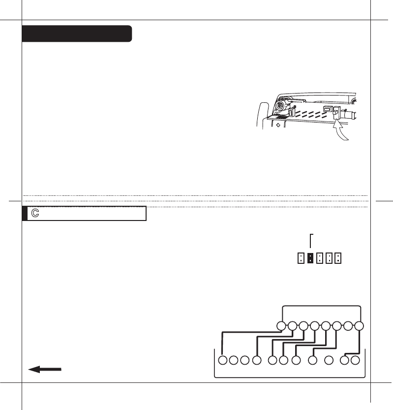
STEP 1 - Connect the R (or RH) wire to the RH terminal on
the Wall Unit. This connects the Heater Power to the Wall Unit.
STEP 2 - Connect the W wire to the W on the Wall Unit.
This connects the heater control line to the 6021z system.
STEP 3 - C wire to the C on the Wall Unit for 24vac power.
NOTE: For gas millivolt system, a 24VAC wall adapter must be
connected to the RH and C terminals to power the WALL UNIT
STEP 4 - Set Config jumpers per this diagram.
Your Heater is now connected to the
Wall Unit.
Please Go To Page 9
PG
19
2 Wire Heat Heating GAS MILLIVOLT or 24vac
PG 20
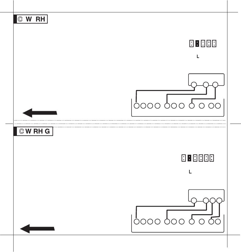
3 Wire Heat
Wall Unit
Terminals
Wall Unit
Terminals
W
R
C
GAS Milivolt Heat
C B O W2 W Y Y2 RH RC G A
W
R G
C
HVAC SYSTEM
C B O W2 W Y Y2 RH RC G A
STEP 1 - Connect the R (or RH) wire to the RH terminal on
the Wall Unit. This connects to the Heater Power .
STEP 2 - Connect the W wire to the W terminal on the Wall
Unit. This connects the heater control line to the 6021z
system.
STEP 3 - Connect the G wire to the G terminal on the
thermostat. This connects the Fan to the Wall Unit.
STEP 4 - C wire to the C on the Wall Unit for 24vac power.
STEP 5 - Set Config jumpers per this diagram.
If you have Electric heat remove 5.
Your system is now connected to the
Wall Unit.
Please Go To Page 9
WIRES WIRES
6 5 4 3 2
SET THERMOSTAT
JUMPERS
SET THERMOSTAT
JUMPERS
6 5 4 3 2 1
remove
if elect
remove
if elect
STEP 1 - Connect the W wire to the W terminal on the
thermostat. This connects to the heater control line.
STEP 2 - Connect the Y wire to the Y terminal on the Wall
Unit. This connects to the Cooler compressor.
STEP 3 - Connect the RH wire to the RH terminal and the
RC wire to the RC terminal on the Wall Unit. This connects
the Heater and Cooler Power.
STEP 4 - Connect the G wire to the G terminal on the
Thermostat. This connects to the Fan.
STEP 5 - C wire to the C on the Wall Unit for 24vac power.
STEP 6 - Remove the RH/RC jumper on the Wall Unit.
STEP 7 - Set Config jumpers per this
diagram. If you have Electric heat
remove jumper 5.
Your HVAC system is now connected
to the Wall Unit.
Please Go To Page 9
STEP 1 - Connect the W wire to the W terminal on the
thermostat. This connects to the heater control line.
STEP 2 - Connect the Y wire to the Y terminal on the Wall
Unit. This connects to the Cooler compressor.
STEP 3 - Connect the RH or R wire to the RH terminal on the
thermostat. This connects the Heater/Cooler Power.
STEP 4 - Connect the G wire to the G terminal on the
Thermostat. This connects to the Fan.
STEP 5 - C wire to the C on the Wall Unit for 24vac power.
STEP 6 - Set Config jumpers per this diagram. If you have
Electric heat remove jumper 5.
Your HVAC system is now connected
to the Wall Unit.
Please Go To Page 9
W Y RH G
PG 21
4 Wire Heat/Cool
Wall Unit
Terminals
YW
R G
C
HVAC SYSTEM
C B O W2 W Y Y2 RH RC G A
WIRES
W Y RH RC G
PG 22
5 Wire Heat/Cool
Wall Unit Terminals
YW
RH RC G
C
HVAC SYSTEM
C B O W2 W Y Y2 RH RC G A
WIRES
remove
if elect
remove
if elect
6 5 4 3 2 1
6 5 4 3 2 1
RH/RC
on Wall Unit
STEP 1 - Connect O wire to the O terminal or B wire to the B terminal on
the Wall Unit. (If you have
both
O and B - connect O wire to O terminal
DO NOT connect B to B terminal - see pg 24 Trane for B wire terminal)
This connects the change-over valve.
STEP 2 - Connect the Y wire to Y on the Wall Unit. This
connects the Compressor.
STEP 3 - Connect the R wire to RH on the Wall Unit. This
connects to the 24vac power.
STEP 4 - Connect the G wire to the G terminal on the Wall
Unit. This connects the Fan.
STEP 5 - C wire to the C on the Wall Unit for 24vac power.
STEP 6 - Set Config jumpers per this
diagram. Set jumper 2. Remove jumper 5.
Your HVAC system is now connected
to the Wall Unit.
Please Go To Page 9
B
or
O Y R G
PG 23
PG 24
4 Wire Heat Pump w/o Aux
WIRES
STEP 1 - Connect O wire to the O terminal or B wire to the B terminal on
the Wall Unit. (If you have
both
O and B -connect O wire to O terminal DO
NOT connect B to B terminal - see pg 24 Trane for B wire terminal)
STEP 2 - Connect the W2 wire to W2 on the Wall Unit.
STEP 3 - Connect the Y wire to Y on the Wall Unit.
STEP 4 - Connect the R wire to RH on the Wall Unit.
STEP 5 - Connect the G wire to G on the Wall Unit.
STEP 6 - C wire to the C on the Wall Unit for 24vac power.
STEP 7 - Set Config jumpers per this diagram. Remove
jumper 5. Use jumper 4 for Gas or Oil aux heat.
Your HVAC system is now connected
to the Wall Unit.
Please Go To Page 9
B
or
O W2 Y RH G 5 Wire Heat Pump w/ Aux Heat
WIRES
Wall Unit Terminals
Wall Unit
Terminals
Set Thermostat Jumpers
YB
R G
C
HEAT PUMP SYSTEM
O
C B O W2 W Y Y2 RH RC G A
set if gas oil AUX
or
or
Y
W2
B
R G
C
HEAT PUMP SYSTEM
O
C B O W2 W Y Y2 RH RC G A
or
or
6 5 4 3 2
6 5 4 3 2
The6021zcanbeusedwithmost24voltgas,oilorelectricheatingandair
conditioningsystems,heatpumpsorgasmillivoltheatingsystems.Itcannot
beusedwith120voltheatingsystems.AskTheHomeDepotforother
thermostatstocontrolthosesystems.
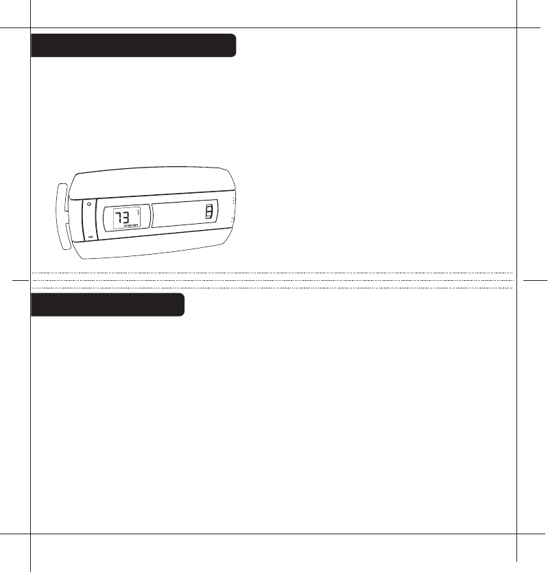
The6021zisdigital.Youcansetyourdesiredheatandcooltemperature
setpointdirectlyontheLargeLCD
display.Youcaneasilyoverridetheset
temperatures.
4-minuteminimumofftimeinCOOL
protectsyourairconditioningsystem
frombeingdamaged.
6021zFeatures
WireReference
Your Wires Ritetemp Terminal
R or V or VR RH and RC Single power for HEAT and COOL
RH or 4 RH Power for HEAT (RH not connected to RC)
RC RC Power for COOL (RH not connected to RC)
W W Heat control
W2 W2 2nd stage HEAT or heat pump auxiliary heat
? A 3rd wire for zoned hot water heat (see zoned)
Y Y COOL control
Y2 Y2 2nd stage COOL control
G or F G FAN control
C or X C Common 24VAC power (to power thermostat)
E Emergency heat (do not connect, tape off)
L System monitor (do not connect, tape off)
T Outdoor sensor (do not connect, tape off)
B or B Heat pump changeover (cool to heat, powered in heat)
O O Heat pump changeover (heat to cool, powered in cool)
B and O SEE NOTE
PG 25
PG 26
B and O
NOTE: If
there are both
B and O wires
(Trane pump
products)
DO NOT
CONNECT B
to B terminal,
connect B to C
terminal
HEAT
HEAT
COOL
OFF
FAN
AUTO
ON
NORMAL
SAVE
ENERGY
Wire Reference cont
Your Wires Ritetemp Terminal
Lennox Heat Pump
V or VR or R RH
M or Y Y
Y or W or W2 W2
F or G G
R or O O
X or X2 or C C
Trane Products [American Standard]
BC
W or W1 W2
Zoned Systems
Your Wires Ritetemp Terminal
2 wire Zoned Hot Water
R RH
W W
3 Wire Zoned Hot Water
Motor Driven Valves
R RH
W W
Y (the 3rd wire) A
3 Wire Zoned Hot Water
Solenoid Valves
R RH
W A
Y (the 3rd wire) W
HEAT PUMP
PUMP AUX
ELECT
CENTIGRADE
OPEN
AUX ONLY
OPEN
PUMP AUX
GAS OR OIL
OPEN
FAHRENHEIT
CLOSEDCLOSED or
CLOSED
CLOSED
NORMAL HEAT (NO PUMP)
OPEN
NORM/PUMP/AUX
CENTIGRADE
RESET UNIT
AFTER JUMPER CHANGE
SELECT
TYPE
AUX
FAHRENHEIT
GAS/OIL
OPEN
ELECTRIC
HEAT
CLOSED
FAN
CONTROL
HEAT PUMP'S
BOTH OPEN
PG
27
PG
28
Jumper Reference
Configuration jumpers allow your
6021z Thermostat to be adapted to
many different HVAC control
applications.
65
43
2
2RESET
BINDING 3
4
5
6
29
This device complies with Part 15 of the FCC Rules. Operation is subject to the
following two conditions: (1) This device may not cause harmful interference, and (2)
This device must accept any interference received, including interference that may
cause undesired operation.
Warning: Changes or modifications to this unit not expressly approved by the party
responsible for compliance could void the user`s authority to operate the equipment.
Note: This equipment has been tested and found to comply with the limits for a Class B
digital device, pursuant to Part 15 of the FCC Rules. These limits are designed to provide
reasonable protection against harmful interference in a residential installation. This
equipment generates,uses and can radiate radio frequency energy and, if not installed and
used in accordance with the instructions,may cause harmful interference to radio
communications. However, there is no guarantee that interference will not occur in a
particular installation. If this equipment does cause harmful interference to radio or
televsion reception, which can be determined by turning the equipment off and on, the user
is encouraged to try to correct the interference by one or more of the following measures:
- Reorient or relocate the receiving antenna.
- Increase the separation between the equipment and receiver.
- Connect the equipment into an outlet on a circuit different from that to which the receiver
is connected.
- Consult the dealer or an experienced radio/TV technician for help.
PG
30
PG
PG1
foldandstaple
PG8
Statementofuse:The6021zcanbeusedwithmillivolt,
24VAC,1and2stageconventionalgas/oil/elecheat,1and2
stageheatpumps,2or3wirezonedhotwater,zonedforced
air,1and2stagecoolingandhybridsystems.
Itcannotbeusedwith120voltheatingsystems.
Celsius
jumper AuxOnly
HeatPump
CustomerSupport:877-505-2353Visitourwebiste
www.ritetemp-thermostats.com 1711-003
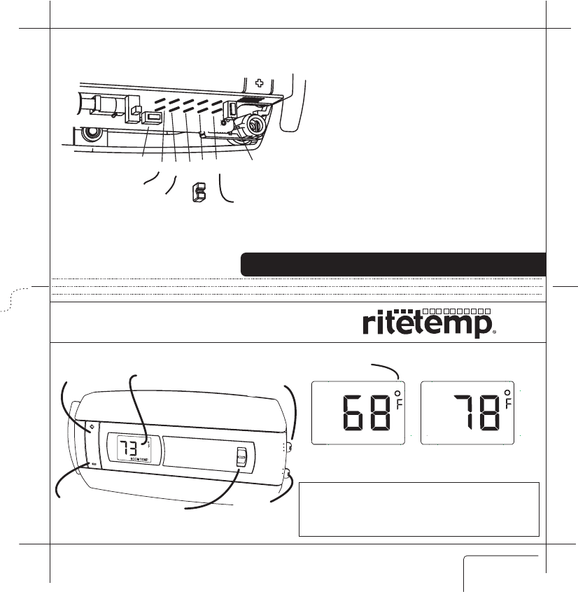
Farenheit/Celcius
indicator
CurrentTemperature
Display
SETTemperature
Display
ROOMTEMP TARGETTEMP
Operation6021z
ENGLISH
Ifyouhaveaheatpumpwithauxiliaryheat,andtheheatpumpisnot
working,youcanusejusttheauxheat.Todothis,changethemodeswitchto
OFF.Nowswitchtoauxheatonlyby
movingthejumperfromposition2
(heatpump)toposition3(auxonly).
TurnmodeswitchbacktoHEAT.
NOTE:Assoonastheheatpumpis
againworking,switchmodetoOFF
andchangethejumperfrom
position3backtoposition2asaux
heatismoreexpensivethanheat
pump.
TosetaHeatPump'sAuxonlymode
Product Name: 6021z
Document Title: Operation guide ENG
Document Type Code: IBOE
Part Number: 711-0033
7nov07 initial release
1nov07 draft1
TEMP
UP button
TEMP
DOWN button
Temperature
Display Mode
Switch
Save
Energy Switch
Fan
Switch
HEAT
HEAT
NORMAL
SAVE
ENERGY
COOL
OFF
FAN
AUTO
ON
2RESET
BINDING 3
4
5
6
PG2
PG3
Configure
SetHEAT/COOLmodeswitchtoHEATorCOOL.Theunitwilldisplaythe
Roomtemperature.SettheFanswitchtoAUTO.
Location
TheThermostatshouldbelocatedinaconvenientlocationintheliving
area.ItisimportanttokeepthethermostatawayfromHVACregisters,
windows,directsun,orabreezyareas.
DonotholdtheThermostatforlongperiodsasyourhands,thiswillheatit
andchangethedisplayedroomtemperature.Ifthisoccursitmaytake20
minutestore-stabilizetotheactualroomtemperature.
PresstheTEMPUPandTEMPDOWNbuttonsontheThermostattoselect
thedesiredtemperature.TheTARGETiconwillbedisplayedwithyour
desiredtemperature.(Displaywillreturntoroomtempin5sec).
Inthewinter,setthesystemswitchtoHEATtocontrolyourheatingsystem.
Inthesummer,setthesystemswitchtoCOOLtocontrolyourAC.
Inspringandfallorwhenwindowsareopen,
youcansetthesystemswitchOFF.
SettingtheFANswitchtoAUTOautomaticallyrunsyoursystem'sfanduring
heatingandcooling.
SettingtheFANswitchtoONrunsyoursystem'sfancontinuouslyeven
withoutheatingorcooling.
Operate
PG5
PG4
SaveEnergySwitch
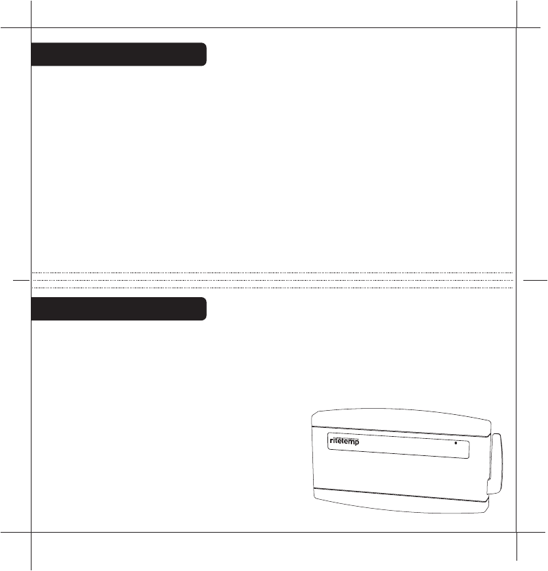
HVACFUNCTIONINDICATORS-TheWallUnitwilllightupthewords
HEAT,COOL,2STG(for2ndstage),andFAN.The2STGwilllightevenif
youdonothavea2ndstageofheatorcool.Thesystemisalwaysready
forthe2ndstage.
COMPRESSORPROTECTION-The
WallUnithasa4minutedelayfor
compressorprotectioninHEATPUMPor
COOL.Thisprotectsthecompressor
fromtofrequentcycling.Whenthe
systemisinthis4mindelay,the
FUNCTIONINDICATORSwillblinkon
theWallUnituntilthe4mindelayisover
andthengosolidandlettheHVACrun.
WallUnitOperation
TheNORMAL/SAVEENERGYswitchallowsyou
tosetacomforttargettemperature(NORMAL)
andanoffsettargettemperature(SAVEENERGY)temperature.Thedefaults
forheattargetsare:NORMAL70F,SAVEENERGY64F.Thedefaultsforcool
targetsare:NORMAL75F,SAVEENERGY80F.However,these4target
temperaturescanbesettoyourpreferencebyusingthe+/-buttons.The
saveenergypositioncouldbeusedwhenyouaregoingtowork,goingto
bed,onvacation,etc.
SettingtheFANswitchtoAUTOautomaticallyrunsyoursystem'sfan
duringheatingandcooling.SettingtheFANswitchtoONrunsthesystems
fancontinuously(ifyouhaveaGwireconnectedtotheWallUnitfromthe
HVAC).
TheThermostatshouldnotbeheldforverylongastheheatfromyour
handswillheatupthe6021Zandeventuallychangethedisplayedroom
temperature.IfthisoccurstheHVACsystemwillactonthisincorrecttemp
readingcausingunreliableresults.
HEATCOOL2STGFAN
BINDINGLOW
BATT
PG7
PG6
F0
/C
0
Select
TheF/Cjumperisunderthetopcoverjumper#6.Itdetermineswhich
temperaturesystemisdisplayedontheLCDdisplay.Withthejumperoff,the
displayisFahrenheit(default).Withthejumperonbothpins,thedisplayis
Centigrade.Whenthisjumperischanged,theunitmustbereset
(underthetopcover).
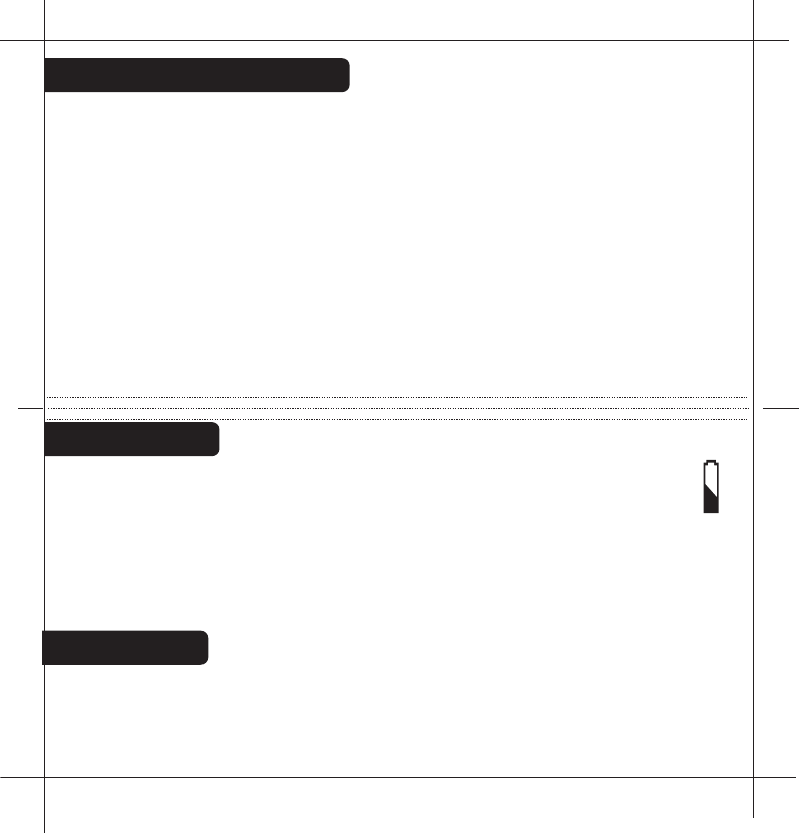
LowBattery
LOWBATTERYThermostat-Whenthebatteriesarelowonthe
Thermnostat,thebatteryiconwillflash.Removethebottomcoverand
replacethetwoAAAbatteriesfirst.Thenremovethebackcoverand
replacethetwoCbatteries.
LOWBATTERYWALLUNIT-WhenthebatteriesarelowontheWall
Unit,theBINDINGLEDwillturnred.Removethetopcoverand
replacethetwoAAAbatteries.
The new ZigBee radio is two way, it sends the command and gets back
confirmation that the command was received and implemented.
There is a radio tower icon on the Thermostat lower right display. If this
icon is not there, communication has been lost. If this occurs, all HVAC
functions are shut off. The radio tower icon also shows a radiation pattern
every time the Thermostat communicates with the WALL UNIT unit.
Though the units are designed to work at least 100 feet from each other
that distance can be affected by interference or blocking from walls etc. If
your Thermostat unit cannot stay in communication (the radio tower icon
does not stay on) you may need a repeater unit between the two which can
be purchased at home depot.
The ZigBee radio system