RadioFrame Networks DH2 DH2 User Manual RFN Customer MOP 3 1
RadioFrame Networks, Inc DH2 RFN Customer MOP 3 1
Installation Guide

Method of Procedure
RadioFrame System
RFN 3.1
May 2003
998-3213-00 Rev B

Method of Procedure
ii RFN_3.1 Beta
Notices
These installation standards have been prepared to provide RadioFrame Networks’ customers with general
standards necessary to ensure that installed RadioFrame Networks equipment operates in accordance with
the design parameters in the owned or leased buildings of RFN’s customers, and its customers, and to
make certain equipment is installed safely and efficiently.
RadioFrame Networks reserves the right to revise this document for any reason, including, but not limited to,
conformity with standards promulgated by various governmental or regulatory agencies, utilization of
advances in the state of the technical arts, or to reflect changes in the design of equipment, techniques, or
procedures described or referred to herein.
Liability to anyone arising out of use or reliance upon any information set forth herein is expressly
disclaimed, and no representation or warranties, expressed or implied, are made with respect to the
accuracy or utility of any information set forth herein.
NOTE: RadioFrame Networks has fully tested up to 6 iDEN RadioBlades per RFU in a full-capacity system
(8 ACUs and 64 RFUs).
Revision History
Software Release Date Sections Updated
iDEN 1.3 May 2002 Phase 0
iDEN 1.4/802.11b 1.3 July 2002 Phase 1
RFN 2.0 December 2002 5.3, 7.1, 7.5
RFN 2.1 December 2002 5.3, 7.1
RFN 3.1 May 2003
To Obtain Copies
Contact RadioFrame Networks at:
• RadioFrame Networks, Inc.
1120 112th Avenue NE, Suite 600
Bellevue, WA 98004
• Telephone (425) 278-2780
• FAX (425) 278-2781
• E-mail USinfo@radioframenetworks.com
Final copies of this document are also posted as .pdf files on the RadioFrame Networks web site at:
http//www.radioframenetworks.com.
Your Comments are Valued
The information in this document is subject to change. Please do not hesitate to point out discrepancies,
express your concerns and make suggestions.
Copyrights and Trademarks
RadioFrame Networks, RadioBlade, and the RadioFrame Networks logo are trademarks or service marks,
and RadioFrame is a registered trademark of RadioFrame Networks, Inc. You may not use these or any
other RadioFrame Networks trademarks or service marks without the written permission of RadioFrame
Networks, Inc. All other trademarks and trade names are the property of their respective owners.
Throughout this publication, the terms RadioFrame Networks, RadioFrame and RFN signify RadioFrame
Networks, Inc.
Method of Procedure/RadioFrame System
© Copyright 2003 RadioFrame Networks, Inc. All Rights Reserved.

RadioFrame System
RFN_3.1 Beta iii
Contents
1 Introduction ............................................................................................................... 1
1.1 Scope of the Manual...................................................................................... 1
1.1.1 Prerequisites and Responsibilities................................................................... 1
1.1.2 Site Documentation ......................................................................................... 2
1.1.3 Reference Documents..................................................................................... 3
1.2 Quality Standards.......................................................................................... 3
1.3 Static Sensitive Precautions ........................................................................3
1.4 Safety Precautions ........................................................................................ 4
1.4.1 Safety Warnings .............................................................................................. 4
1.4.2 Safety with Electricity....................................................................................... 5
1.4.3 Recommendations........................................................................................... 6
1.4.3.1 Safety Recommendations..............................................................6
1.4.3.2 Guidelines for Working on Equipment Powered by Electricity .......6
1.4.3.3 In the Event of an Electrical Accident ............................................6
2 System Description...................................................................................................7
2.1 Functional Relationships.............................................................................. 7
2.1.1 The iDEN Interface .......................................................................................... 8
2.1.1.1 integrated Site Controller (iSC-3)...................................................8
2.1.1.2 GPS Antennas .............................................................................10
2.1.1.3 Channel Service Unit (CSU) ........................................................11
2.1.2 RadioFrame System (RFS) ........................................................................... 11
2.1.2.1 Network Chassis Unit (NCU) .......................................................12
2.1.2.2 Airlink Chassis Unit (ACU) ...........................................................13
2.1.2.3 RadioFrame Unit (RFU) ...............................................................14
2.1.2.4 iDEN RadioBlade (RadioBlade or RB).........................................14
2.1.2.5 802.11b RadioFrame Access Point (RAP)...................................15
2.1.2.6 Universal Repeater Unit (URU)....................................................15
2.1.2.7 Ethernet Media Converter............................................................15
2.1.3 Power Plant ................................................................................................... 15
2.1.3.1 Rectifier........................................................................................16
2.1.3.2 Battery Plant ................................................................................16
2.1.4 Local Area Network (LAN)............................................................................. 17
2.2 Physical Relationships ............................................................................... 18
2.2.1 Main Rack...................................................................................................... 19
2.2.2 Remote ACUs................................................................................................ 21
2.2.3 RFUs ............................................................................................................. 21
2.2.3.1 RadioBlades and RAPS...............................................................21
2.2.4 LAN................................................................................................................ 22
3 Pre-Installation ........................................................................................................ 23
3.1 Receipt of Equipment.................................................................................. 23
3.1.1 Equipment Inspection .................................................................................... 23
3.1.2 Equipment Inventory...................................................................................... 24

Method of Procedure
iv RFN_3.1 Beta
3.1.3 RadioFrame Networks Documents Shipped with the RFS............................ 24
3.2 Site Planning................................................................................................ 25
3.2.1 Site Considerations ....................................................................................... 25
3.2.1.1 Main Rack ....................................................................................25
3.2.1.2 Remote ACUs ..............................................................................26
3.2.1.3 RFUs............................................................................................26
3.2.1.4 LAN ..............................................................................................26
3.3 Main Rack and Supporting Hardware........................................................ 26
3.3.1 Mounting........................................................................................................ 27
3.3.1.1 Plumb and Squareness................................................................27
3.3.1.2 Anchoring.....................................................................................27
3.3.1.3 Mounting on Concrete Floors.......................................................27
3.3.1.4 Isolated Mounting.........................................................................28
3.3.1.5 Mounting on Wood or Fiberglass Floors ......................................28
3.3.1.6 Anchoring Equipment to Raised Floors .......................................29
3.3.1.7 Seismic Anchoring .......................................................................29
3.3.2 Clearances .................................................................................................... 32
3.3.2.1 Back.............................................................................................33
3.3.2.2 Front.............................................................................................33
3.3.2.3 Sides............................................................................................34
3.3.2.4 Above...........................................................................................34
3.3.3 Weight ........................................................................................................... 34
3.3.4 Power ............................................................................................................ 35
3.3.5 Grounding...................................................................................................... 36
3.3.6 Environment .................................................................................................. 36
3.3.7 Heat Load ...................................................................................................... 37
3.3.8 GPS Antennas............................................................................................... 38
3.3.9 Surge Arrestors ............................................................................................. 38
3.3.10 Cable Support................................................................................................ 39
3.3.10.1 Securing cabling within racks or cabinets....................................39
3.3.10.2 Routing cables within racks and cabinets ....................................39
3.3.10.3 Protecting cables within racks and cabinets ................................40
3.3.10.4 Cable bending radius within racks and cabinets..........................40
3.3.10.5 Cable separation and grouping within racks or cabinets .............40
3.3.11 Alarm Blocks.................................................................................................. 40
3.4 Remote ACUs............................................................................................... 40
3.4.1 Mounting........................................................................................................ 41
3.4.2 Clearances .................................................................................................... 41
3.4.2.1 Back.............................................................................................41
3.4.2.2 Front.............................................................................................41
3.4.2.3 Sides............................................................................................41
3.4.2.4 Above...........................................................................................41
3.4.3 Weight ........................................................................................................... 41
3.4.4 Power ............................................................................................................ 41
3.4.5 Grounding...................................................................................................... 42
3.4.6 Environment .................................................................................................. 42
3.4.7 Heat Load ...................................................................................................... 42

RadioFrame System
RFN_3.1 Beta v
3.4.8 Cable Support................................................................................................ 42
3.5 RFUs ............................................................................................................. 42
3.5.1 Location ......................................................................................................... 42
3.5.2 Mounting........................................................................................................ 43
3.5.3 Clearances .................................................................................................... 43
3.5.3.1 Back.............................................................................................43
3.5.3.2 Front.............................................................................................43
3.5.3.3 Sides............................................................................................43
3.5.3.4 Above...........................................................................................43
3.5.4 Weight ........................................................................................................... 44
3.5.5 Power ............................................................................................................ 44
3.5.6 Grounding...................................................................................................... 44
3.5.7 Environment .................................................................................................. 44
3.5.8 Heat Load ...................................................................................................... 44
3.5.9 RF Exposure.................................................................................................. 44
3.5.10 Cable Support................................................................................................ 44
3.6 RadioBlades................................................................................................. 45
3.6.1 Mounting........................................................................................................ 45
3.6.2 Clearances .................................................................................................... 45
3.6.2.1 Back.............................................................................................45
3.6.2.2 Front.............................................................................................45
3.6.2.3 Sides............................................................................................45
3.6.2.4 Above...........................................................................................45
3.6.3 Weight ........................................................................................................... 45
3.6.4 Power ............................................................................................................ 45
3.6.5 Grounding...................................................................................................... 46
3.6.6 Environment .................................................................................................. 46
3.6.7 Heat Load ...................................................................................................... 46
3.7 RAPs ............................................................................................................. 46
3.7.1 Mounting........................................................................................................ 46
3.7.2 Clearances .................................................................................................... 46
3.7.2.1 Back.............................................................................................46
3.7.2.2 Front.............................................................................................47
3.7.2.3 Sides............................................................................................47
3.7.2.4 Above...........................................................................................47
3.7.3 Weight ........................................................................................................... 47
3.7.4 Power ............................................................................................................ 47
3.7.5 Grounding...................................................................................................... 47
3.7.6 Environment .................................................................................................. 47
3.7.7 Heat Load ...................................................................................................... 47
3.8 URU............................................................................................................... 48
3.8.1 Mounting........................................................................................................ 48
3.8.2 Clearances .................................................................................................... 48
3.8.2.1 Back.............................................................................................48
3.8.2.2 Front.............................................................................................48
3.8.2.3 Sides............................................................................................48
3.8.2.4 Above...........................................................................................48

Method of Procedure
vi RFN_3.1 Beta
3.8.3 Weight ........................................................................................................... 48
3.8.4 Power ............................................................................................................ 48
3.8.5 Grounding...................................................................................................... 49
3.8.6 Environment .................................................................................................. 49
3.8.7 Heat Load ...................................................................................................... 49
3.9 Interconnecting Cabling .............................................................................49
3.9.1 T1 .................................................................................................................. 49
3.9.2 Power Cabling ............................................................................................... 50
3.9.2.1 AC Power Cabling........................................................................50
3.9.2.2 DC Power Cabling .......................................................................51
3.9.3 Category 5 Cabling........................................................................................ 52
3.9.3.1 Case Type....................................................................................53
3.9.3.2 Connecting Hardware ..................................................................53
3.9.3.3 Cable and Connector Wiring........................................................53
3.9.4 Installation ..................................................................................................... 54
3.9.4.1 NEC Compliance .........................................................................55
3.9.4.2 Local Jurisdictions........................................................................55
3.9.4.3 Routes..........................................................................................55
3.9.4.4 Testing .........................................................................................56
3.9.4.5 Labeling .......................................................................................57
3.10 Main Rack Configuration ............................................................................ 58
3.11 RF Planning.................................................................................................. 60
3.12 Site Survey ................................................................................................... 60
3.13 Alarm Configuration.................................................................................... 60
3.14 Tools Required ............................................................................................ 60
3.14.1 Hand Tools .................................................................................................... 60
3.14.2 Laptop Computer........................................................................................... 61
3.14.3 System Manager Software ............................................................................ 61
3.14.4 IP Addresses for all cards in the RFS............................................................ 61
3.14.5 iSC-3 Configuration ....................................................................................... 61
3.14.6 Test Equipment ............................................................................................. 61
3.14.7 Additional Materials ....................................................................................... 62
4 Installation ............................................................................................................... 63
4.1 Main Rack and Supporting Hardware........................................................ 63
4.1.1 Main Rack...................................................................................................... 63
4.1.2 Auxiliary Equipment....................................................................................... 64
4.1.2.1 GPS Antennas .............................................................................64
4.1.2.2 Environmental Alarm Block..........................................................65
4.1.2.3 Mandatory Alarms........................................................................66
4.1.2.4 Surge Arrestors............................................................................67
4.1.2.5 Grounding ....................................................................................67
4.1.2.6 Cable Supports ............................................................................68
4.2 Remote ACUs............................................................................................... 68
4.2.1 Mount the remote ACU.................................................................................. 68
4.2.2 Connect the ACU to the NCU and the RFUs................................................. 69

RadioFrame System
RFN_3.1 Beta vii
4.3 URU............................................................................................................... 70
4.3.1 Installing a URU............................................................................................. 70
4.3.2 Changing the URU Mode of Operation.......................................................... 71
4.4 RFU ............................................................................................................... 72
4.4.1 Mounting and Anchoring................................................................................ 72
4.4.1.1 Wall Mount ...................................................................................73
4.4.1.2 Ceiling Mount ...............................................................................73
4.4.2 Connect the RFUs to the ACU ...................................................................... 74
4.4.3 Insert the RadioBlades and RAPs into the RFU............................................ 75
4.5 Interconnecting Cabling .............................................................................77
4.5.1 T1 .................................................................................................................. 77
4.5.2 RFS to iDEN Interface ................................................................................... 78
4.5.3 RFS to Customer LAN................................................................................... 80
4.5.4 Punch Block to EAS ...................................................................................... 80
5 Equipment Commissioning.................................................................................... 82
5.1 iDEN Interface .............................................................................................. 82
5.2 Power Plant .................................................................................................. 82
5.3 RadioFrame System .................................................................................... 83
5.3.1 Start System Manager................................................................................... 83
5.3.2 Navigating the System Configuration ............................................................ 85
5.3.3 Checking the Status of RFS Components..................................................... 86
5.3.4 Configuring the NCU ..................................................................................... 87
5.3.5 Configuring the ACUs.................................................................................... 88
5.3.6 Configuring the RFUs .................................................................................... 89
5.3.7 Viewing Hardware and Software Versions .................................................... 89
5.3.8 Changing the Default iDEN BR Cabinet Position .......................................... 91
5.4 Coverage Validation .................................................................................... 92
5.4.1 Detailed Building Plans—RF Modeling.......................................................... 92
5.4.2 Measurement-based Estimate....................................................................... 92
5.4.3 Floor Plan Estimate ....................................................................................... 92
5.5 Site Acceptance Guidelines .......................................................................92
5.5.1 Site As-Built Documentation.......................................................................... 92
5.5.2 Site As-Built Acceptance Test Procedures.................................................... 93
5.5.2.1 Grounding ....................................................................................94
5.5.2.2 Power Plant..................................................................................94
5.5.2.3 Battery..........................................................................................94
5.5.2.4 Main Rack ....................................................................................95
5.5.2.5 T1 Line.........................................................................................95
5.5.3 RadioFrame System As-Built Documentation ............................................... 95
5.5.3.1 Equipment Inventory ....................................................................95
5.5.3.2 Cabling Pathways ........................................................................96
5.5.3.3 Floor Plan/Site Drawing ...............................................................96
5.5.4 RadioFrame System Acceptance Test .......................................................... 96
5.6 RadioFrame System Functionality Test .................................................... 96
5.6.1 RadioFrame System iDEN Functionality Test ............................................... 97

Method of Procedure
viii RFN_3.1 Beta
5.6.1.1 Interconnect & Dispatch Setup & Voice Quality...........................97
5.6.1.2 Packet Data Service Connection and Latency.............................99
5.6.1.3 Short Message Service..............................................................100
5.6.1.4 Handover and Cell Reselection .................................................100
5.6.1.5 Interconnect Connection Stability and SQE Performance .........101
5.6.1.6 Dispatch Connection Stability ....................................................101
5.6.1.7 Idle SQE Testing and Validation ................................................101
5.6.1.8 System Self-Recovery Test .......................................................102
5.6.1.9 Packet Data Stability and Throughput .......................................102
5.6.1.10 Validation of ‘Unable to Key BR’ Alarm......................................103
5.6.2 Rectifier & AC Power Alarms....................................................................... 103
5.6.3 iSC-3 Functionality Test .............................................................................. 103
6 Connecting the RFS to the Customer LAN ......................................................... 104
6.1 Connect the NCU to the Customer LAN .................................................. 104
6.2 Configure the RFS Global 802.11 Services ............................................. 104
6.2.1 Service Set Identity (SSID).......................................................................... 107
6.2.2 WEP Encryption .......................................................................................... 108
6.2.2.1 Encryption (On/Off) ....................................................................108
6.2.2.2 Shared Key Authentication ........................................................108
6.2.2.3 WEP Keys..................................................................................108
6.2.3 Enhanced Security ...................................................................................... 109
6.2.4 User Access Control.................................................................................... 109
6.2.5 Add/Remove MAC Addresses..................................................................... 109
6.2.5.1 Adding MAC Addresses.............................................................110
6.2.5.2 Removing MAC Addresses........................................................110
6.2.5.3 Saving MAC Addresses .............................................................110
6.3 Configuring an Individual RAP................................................................. 111
6.4 Viewing WLAN User/RAP Associations ..................................................113
6.5 Verifying the Wireless LAN (802.11b) Installation .................................. 114
7 Operations and Maintenance ............................................................................... 115
7.1 Upgrading System Software..................................................................... 115
7.2 Preventive Maintenance............................................................................ 115
7.2.1 iSC-3............................................................................................................ 115
7.2.2 Power Plant ................................................................................................. 115
7.2.2.1 Semi-Annual Maintenance.........................................................116
7.2.2.2 Annual Maintenance ..................................................................116
7.2.3 Batteries ...................................................................................................... 118
7.2.4 RadioFrame System.................................................................................... 118
7.3 Corrective Maintenance ............................................................................ 118
7.3.1 iSC-3............................................................................................................ 119
7.3.2 Power Plant ................................................................................................. 121
7.3.3 RadioFrame System.................................................................................... 122
7.3.3.1 Network Chassis Unit.................................................................122
7.3.3.2 Airlink Chassis Unit ....................................................................124
7.3.3.3 RadioFrame Unit........................................................................125

RadioFrame System
RFN_3.1 Beta ix
7.3.3.4 Universal Repeater Unit.............................................................125
7.4 Field Replaceable Units ............................................................................ 126
7.4.1 iSC-3............................................................................................................ 126
7.4.2 Power Plant ................................................................................................. 126
7.4.2.1 Removal and Replacement of Distribution CBs.........................126
7.4.2.2 Rectifier Removal and Replacement .........................................127
7.4.3 RadioFrame System.................................................................................... 127
7.5 Alarm Resolution Procedures .................................................................. 129
7.5.1 Viewing System Manager Alarms................................................................ 129
7.5.2 OMC Alarm Code and Severity Levels........................................................ 131
7.5.3 System Manager Alarms ............................................................................. 132
7.6 Repair and Technical Support.................................................................. 136
7.6.1 Before calling............................................................................................... 136
7.6.2 Technical Assistance Center ....................................................................... 137
7.6.3 Repair Procedure ........................................................................................ 137
Appendix A Glossary ............................................................................................... 138
Appendix B Site Survey ........................................................................................... 140
Appendix C NCU and ACU Main Rack Installation ................................................ 147
Appendix D RFS Default IP Addresses................................................................... 150
Appendix E RF Planning Guide 990-1001-00 ......................................................... 152
Appendix F System Manager Guide 981-6300-00.................................................. 152
Appendix G RFN Recommended Data Fill 998-0100-10 ....................................... 152
Appendix H RFN Field Guide 998-1000-00 ............................................................. 152

Method of Procedure
x RFN_3.1 Beta
List of Figures
Figure 1 The RadioFrame Networks iDEN/802.11b solution consists of the iDEN
Interface, the RadioFrame System, a Power Plant, and the customer’s
Local Area Network. ..................................................................................... 7
Figure 2 The iSC-3 functional diagram. ...................................................................... 8
Figure 3 Environmental Alarm System functional diagram....................................... 10
Figure 4 The RadioFrame System uses a ‘tree’-style architecture to connect
components. ............................................................................................... 12
Figure 5 NCU functional diagram. ............................................................................ 13
Figure 6 ACU functional diagram.............................................................................. 13
Figure 7 RFU functional diagram.............................................................................. 14
Figure 8 iDEN RadioBlade functional diagram. ........................................................ 15
Figure 9 RadioFrame Access Point (RAP) functional diagram. ................................ 15
Figure 10 RFS and customer LAN functional diagram. .............................................. 17
Figure 11 A typical RadioFrame System iDEN/802.11b installation........................... 19
Figure 12 The main rack houses the iDEN interface, the NCU and one ACU of the
RadioFrame System, and the Power Plant. ............................................... 20
Figure 13 RFUs are located throughout the building to provide coverage.................. 21
Figure 14 RadioBlade and RAP antennas must point straight down to the ground.... 22
Figure 15 Telco (T1/E1) interface with the iDEN/802.11b RFS. ................................. 38
Figure 16 T568B standard. ......................................................................................... 54
Figure 17 Standard 19" 7’ rack configuration and power requirements for the
RadioFrame System................................................................................... 59
Figure 18 Environmental Alarm Block ........................................................................ 66
Figure 19 Mount the ACU only in an EIA-standard compliant 19” rack. ..................... 69
Figure 20 Connect Port 1 on the front of the ACU to the specified port (1-8) on the
back of the NCU. Connect RFUs to Ports 1-8 on the back of the ACU...... 70
Figure 21 The URU can be placed or mounted on any flat surface............................ 71
Figure 22 The URU dip switch is located on the bottom of the unit and is used to
configure the input and output power for the unit. ...................................... 72
Figure 23 A wall mount requires two screws to anchor the RFU................................ 73
Figure 24 Use the provided bracket when mounting an RFU on the ceiling,
ensuring that all bolts or screws penetrate wood........................................74
Figure 25 Connect the RFU to the ACU, then ensure that the RFU is receiving
power and connectivity from the ACU. ....................................................... 75

RadioFrame System
RFN_3.1 Beta xi
Figure 26 Slide each iDEN RadioBlade into the specified slot in the RFU. ................ 76
Figure 27 Place the ground strap(s) between the iDEN RadioBlades and their
antennas..................................................................................................... 76
Figure 28 Insert the 802.11b RAPs into the specified slots of the RFU...................... 77
Figure 29 T1 interface cable configuration ................................................................. 78
Figure 30 Connecting the RFS to an iSC-3 requires using an Ethernet Media
Converter.................................................................................................... 79
Figure 31 Punch Block 1: EAS pinout......................................................................... 81
Figure 32 Connect Port 2 on the front of the NCU to the customer’s LAN. .............. 104
Figure 33 Each global 802.11 configuration setting has a separate “save” button... 106
Figure 34 Replacing a board in an NCU or an ACU. ................................................ 128
Figure 35 Alarms are listed up to 200 at time and continue to scroll as events
occur. 130
Figure 36 Mount the NCU only in an EIA-standard compliant 19” rack. ................... 148
Figure 37 Mount the ACU only in an EIA-standard compliant 19” rack. ................... 149
Figure 38 Connect the RJ45-to-RJ45 CAT 5 cable for each ACU to the specified
RJ45 port on the back of the NCU............................................................ 149

Method of Procedure
xii RFN_3.1 Beta

RadioFrame System
Introduction
RFN_3.1 Beta 1
1 Introduction
1.1 Scope of the Manual
This manual describes standards for installing, modifying and maintaining
RadioFrame Networks’ equipment at RadioFrame customer sites. All
specifications and requirements pertain to the RadioFrame Networks equipment
required in RFN customer iDEN (integrated Digital Enhanced Network) and
802.11b installations. RadioFrame Networks recommends reading the entire
manual before attempting to install or operate RadioFrame Networks equipment.
1.1.1 Prerequisites and Responsibilities
All installers are required to be trained and certified to install RadioFrame
Networks equipment as follows:
• Installers shall be trained for specific equipment or the warranty on that
equipment may be invalidated.
• All installers shall be able to use required tools and test equipment properly.
• Installers shall clean up and properly store tools at the end of each day’s
work.
The installation Project Manager shall be responsible for, but not limited to:
• Ensuring that all detailed engineering specifications, job drawings, technical
information, and documentation required to successfully complete an
installation are on site.
• Making an inventory and conducting a visual inspection of all equipment
shipped to the job site prior to the installation.
• Identifying any physical damage, defects, or problems that may prevent the
proper installation, maintenance, or operation of equipment and reporting this
information to the proper parties involved.
• Ensuring that all installation job activities are completed in a safe and
professional manner whether or not the specific activity is mentioned in this
manual.
• Ensuring that all locations where painted surfaces have been marred are
touched up. The touch-up paint shall be the same quality and shade as the
paint used on the item being touched up.
• Using this Method of Procedure/RadioFrame System manual to ensure that
each specific job has been performed.
• Ensuring that the site is cleaned up after installation.
Method of Procedure
Introduction
2 RFN_3.1 Beta
Preparation of a site and installation of equipment requires close coordination
between RFN, RFN’s customer and its customers, and designated third-party
RFN Certified Integration Partner(s). Domains of responsibilities are shown in the
following table.
Task Responsible Party
Prepares system design and quotes RFN Customer
Provides Project Management, including site survey RFN Customer
Constructs site, including racks, ironwork (ceiling support,
ladder racks, etc.), AC power, DC power, and battery
backup systems.
RFN Customer/Customer
Lays conduit and cable, installs new fiber raceways, and fire
stopping after cables have been laid.
RFN Certified Integration Partner
Installs, tests, and commissions RadioFrame Networks
equipment, including site acceptance.
RFN Certified Integration Partner
Maintains RadioFrame Networks equipment, including
logbook.
RFN Customer/Customer
1.1.2 Site Documentation
The following documents are required for installing, commissioning, testing, and
maintaining RadioFrame Networks equipment. Some or all of this documentation
will be left on site. In addition, a logbook will be stored on site that will be used for
tracking all changes, updates, and maintenance work done on RadioFrame
System equipment.
Document
Site Survey
Pre-Installation Checklist
Equipment Inventory
Site Acceptance Test
Equipment Functionality Acceptance Test
Site As-built
Site As-built Acceptance Test
Equipment As-built
Equipment As-built Acceptance Test
Alarms
Alarm Procedures

RadioFrame System
Introduction
RFN_3.1 Beta 3
1.1.3 Reference Documents
The following documents are intended to supplement the information contained
in this manual.
• RF Planning Guidelines for iDEN Installations, RadioFrame Networks,
990-1001-00
• Customer Release Notes RFN_3.1, RadioFrame Networks,
P/N 991-1000-31
• Gen 3 Site Controller System Manual, Motorola, 68P80801E30-O
• PECO II Rectifier System Manual: 127NHL-IBWS
• PECO II System Manual 40-719010-1005
• Battery Manufacturer’s Installation and Maintenance Documentation
• Quality Standards—Fixed Network Equipment (FNE) Installation Manual
(R56), Motorola, R56 current edition
• National Electrical Code (NEC), current edition
1.2 Quality Standards
The installation section of this manual requires the Motorola Quality Standards-
Fixed Network Equipment (FNE) Installation Manual (R56) as a reference. The
R56 contains onsite installation, integration, optimization, and maintenance
information for trunked radio equipment. Technicians and installation personnel
must be familiar with procedures and guidelines presented within the R56
manual.
1.3 Static Sensitive Precautions
Electrostatic discharge (ESD) can damage equipment and impair electrical
circuitry. It occurs when electronic printed circuit cards are improperly handled
and can result in complete or intermittent failures.
Extreme care must be taken while handling, shipping, and servicing boards and
RadioBlades. To avoid static damage, observe the following precautions:
• Prior to handling, shipping, and servicing equipment, always put on a
conductive wrist strap connected to a grounding device. This discharges any
accumulated static charges. All RFN RadioBlades and Field Replaceable
Units (FRUs), including NPCs and APCs, are shipped with a disposable anti-
static wrist strap (RFN P/N 110-0610-00).
Warning!
Use extreme caution when wearing a conductive wrist strap near sources of high
voltage. The low impedance provided by the wrist strap also increases the danger
of lethal shock should accidental contact with high voltage sources occur.

Method of Procedure
Introduction
4 RFN_3.1 Beta
• Handle boards by the edges and avoid touching any conductive parts of the
board with your hands.
• Never remove a board with power applied to the unit (hot-pull) unless you
have verified it is safe to do so. Make sure the unit will not be damaged by
removing the board.
• Avoid carpeted areas, dry environments, and certain types of clothing (silk,
nylon, etc.) during service or repair due to the possibility of static buildup.
• Apply power to the circuit under test before connecting low impedance test
equipment (such as pulse generators, etc.). When testing is complete,
disconnect the test equipment before power is removed from the circuit under
test.
• Be sure to ground all electrically powered test equipment. Connect a ground
lead (-) from the test equipment to the board or module before connecting the
test probe (+). When testing is complete, remove the test probe first, and then
remove the ground lead.
• Place all boards and RadioBlades on a conductive surface (such as a sheet
of aluminum foil) when removed from the system. The conductive surface
must be connected to ground through 100kΩ.
• Never use non-conductive material for packaging boards or RadioBlades for
shipment or storage. All units should be wrapped with anti-static (conductive)
material. Replacement units shipped from the factory are packaged in a
conductive material.
• If possible, retain all original packing material for future use.
1.4 Safety Precautions
Read all the notices in this section prior to installing or using the RadioFrame
System or any of its components.
1.4.1 Safety Warnings
Warning!
Only trained and qualified personnel should be allowed to install, replace, or
service this equipment.
Warning!
This product relies on the building’s installation for short-circuit (over current)
protection. Ensure that a fuse or circuit breaker no larger than 120VAC, 15A U.S.
(240VAC, 10A international) is used on the phase conductors (all current-carrying
conductors).
RadioFrame System
Introduction
RFN_3.1 Beta 5
Warning!
To comply with FCC RF exposure requirements, iDEN antennas must be installed
to provide at least 8 inches (20 cm) separation from all persons, with antenna gain
not exceeding zero (0) dBi.
Warning!
Never defeat the ground conductor or operate the equipment in the absence of a
suitably installed ground conductor. Contact the appropriate electrical inspection
authority or an electrician if you are uncertain that suitable grounding is available.
Warning!
The plug-socket combination must be accessible at all times because it serves as
the main disconnecting device.
Warning!
The RadioFrame Unit (RFU) is intended to be mounted on a wall. The RFU can
also be installed on or above a ceiling. Please read the RFU mounting instructions
carefully before beginning the installation. Failure to use the correct hardware or to
follow the correct procedures could result in a hazardous situation to people and
damage to the system.
Warning!
Ultimate disposal of this product should be handled according to all national laws
and regulations.
1.4.2 Safety with Electricity
Warning!
To avoid electric shock, do not connect safety extra-low voltage (SELV) circuits to
telephone-network voltage (TNV) circuits. LAN ports contain SELV circuits, and
WAN ports contain TNV circuits. Some LAN and WAN ports both use RJ45
connectors; incorrect interconnection can cause equipment damage. Use caution
when connecting cables.
Warning!
Before working on equipment that is connected to power lines, remove jewelry
(including rings, necklaces, and watches). Metal objects will heat up when
connected to power and ground and can cause serious burns or weld the metal
object to the terminals.
Warning!
Hazardous network voltages are present in WAN ports regardless of whether
power to the attached equipment is OFF or ON. To avoid electric shock, use
caution when working near WAN ports. When detaching cables, detach the end
away from the router first.
Warning!
Do not touch the power supply when the power cord is connected. For systems
with a power switch, line voltages are present within the power supply even when
the power switch is off and the power cord is connected. For systems without a
power switch, line voltages are present within the power supply when the power
cord is connected.

Method of Procedure
Introduction
6 RFN_3.1 Beta
1.4.3 Recommendations
1.4.3.1 Safety Recommendations
• Keep tools away from walk areas where you and others could fall over them.
• Wear safety glasses if you are working under any conditions that might be
hazardous to your eyes.
• Do not perform any action that creates a potential hazard to people or makes
the equipment unsafe.
1.4.3.2 Guidelines for Working on Equipment Powered by Electricity
• Locate the emergency power off switch for the room in which you are
working. Then, if an electrical accident occurs, you can act quickly to turn off
the power.
• Before installing, removing, or repairing an NCU, ACU or URU, unplug the
power cord.
• Disconnect all power before working near power supplies.
• Do not work alone if potentially hazardous conditions exist.
• Never assume that power is disconnected from a circuit. Always check.
• Look carefully for possible hazards in your work area, such as moist floors,
ungrounded extension cables, frayed power cords, and missing safety
grounds.
1.4.3.3 In the Event of an Electrical Accident
• Use caution; do not become a victim yourself.
• Turn off power to the system.
• If possible, send another person to get medical aid. Otherwise, assess the
condition of the victim and then call for help.
• Determine if the victim needs rescue breathing or external cardiac
compressions, then take appropriate action.

RadioFrame System
System Description
RFN_3.1 Beta 7
2 System Description
The RadioFrame Networks iDEN/802.11b solution generates RF within the
building using low-power transceivers that are placed as needed to meet
coverage and capacity requirements. The low-power nature of the transceivers
minimizes interference with the surrounding macrocell system so that the
macrocell system views the RFN iDEN/802.11b solution as a peer. The RFN
iDEN/802.11b solution is remotely monitored down to the component level,
including alarms and system performance, using a web-based interface.
The RadioFrame Networks iDEN/802.11 solution consists of the following four
systems:
• iDEN Interface
• RadioFrame System
• Power Plant
• Local Area Network
2.1 Functional Relationships
The following diagram depicts the components of each system in the
RadioFrame Networks iDEN/802.11 solution.
Figure 1 The RadioFrame Networks iDEN/802.11b solution consists of the iDEN
Interface, the RadioFrame System, a Power Plant, and the customer’s
Local Area Network.
NCU
ACU(s)
RFU(s)
iDEN RadioBlades
RadioFrame Access Points (RAPs)
Ethernet Media Converter
URU(s)
RadioFrame System
iSC-3
EAS
CSU
GPS Antennas
Rectifier
Batteries
Power Plant
iDEN Interface
Customer-
defined LAN
equipment
Local Area Network
Method of Procedure
System Description
8 RFN_3.1 Beta
2.1.1 The iDEN Interface
The iDEN (integrated Digital Enhanced Network) interface supplies T1 and GPS
antenna connections, via the iSC-3, for the RadioFrame System. The iDEN
interface also provides an Environmental Alarm System (EAS) and a Channel
Service Unit (CSU) for the T1 input to the iSC-3.
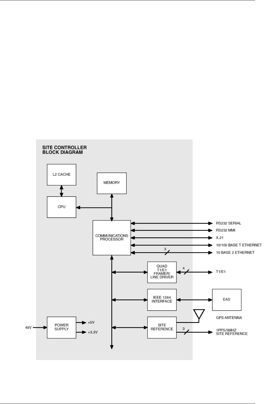
2.1.1.1 integrated Site Controller (iSC-3)
The integrated Site Controller, or iSC-3, consists of a site controller and an
Environmental Alarm System (EAS). Most systems are configured with two
iSC-3s (an active and a standby) and one EAS. For more information about the
iSC-3, refer to the Motorola document Gen 3 Site Controller System Manual,
68P80801E30-O.
Figure 2 The iSC-3 functional diagram.

RadioFrame System
System Description
RFN_3.1 Beta 9
Site Controller CPU Board
The following is a list of CPU Board main features:
• PPC750 host processor with 1MByte L2 cache
• MPC8260 communications processor for all serial I/O
• 32 MBytes of FLASH on the PPC bus
• 64 MBytes of SDRAM on the PPC bus
• 16 MBytes SDRAM on the MPC8260 local bus
• 32 KBytes battery backed SRAM with real time clock on the MPC8260 local
bus
• Four E1/T1 span lines supported by a single quad E1/T1 framer/line driver IC
• One 10/100BaseT Ethernet port
• Three 10Base2 Ethernet ports
• One X.21 port
• One IEEE 1284 parallel port
• Two RS232 serial ports
• Internal or remote GPS Receiver
• Three time/frequency reference outputs
Environmental Alarm System (EAS)
The EAS provides a central location for site alarm signal processing. The EAS
monitors site environmental conditions, including AC power, smoke alarms,
intrusion alarms, antenna tower lights, etc.
The Site Controller and EAS interact in a master/slave relationship. The Site
Controller sends commands to the EAS to determine the status of alarm inputs or
set the state of control outputs. The EAS, in turn, sends alarm status responses
to the Site Controller.
The EAS continuously scans the status of the alarm inputs, ensuring that all
alarms are consistently monitored.
Alarm wiring routes directly from the RadioFrame Networks site equipment and
power supply equipment to the EAS. The EAS sends alarm status to the site
controller via the IEEE 1284 parallel connection.
The EAS can monitor up to 48 inputs, each of which must be a contact closure
between the alarm input and its return. Alarm inputs are optically isolated. The
EAS also provides eight relay outputs. Four RJ45 connectors replicate the
physical interfaces to the three RF cabinets and one control cabinet. The
remaining alarm inputs and relay outputs are accessible via two 50-pin DSUB
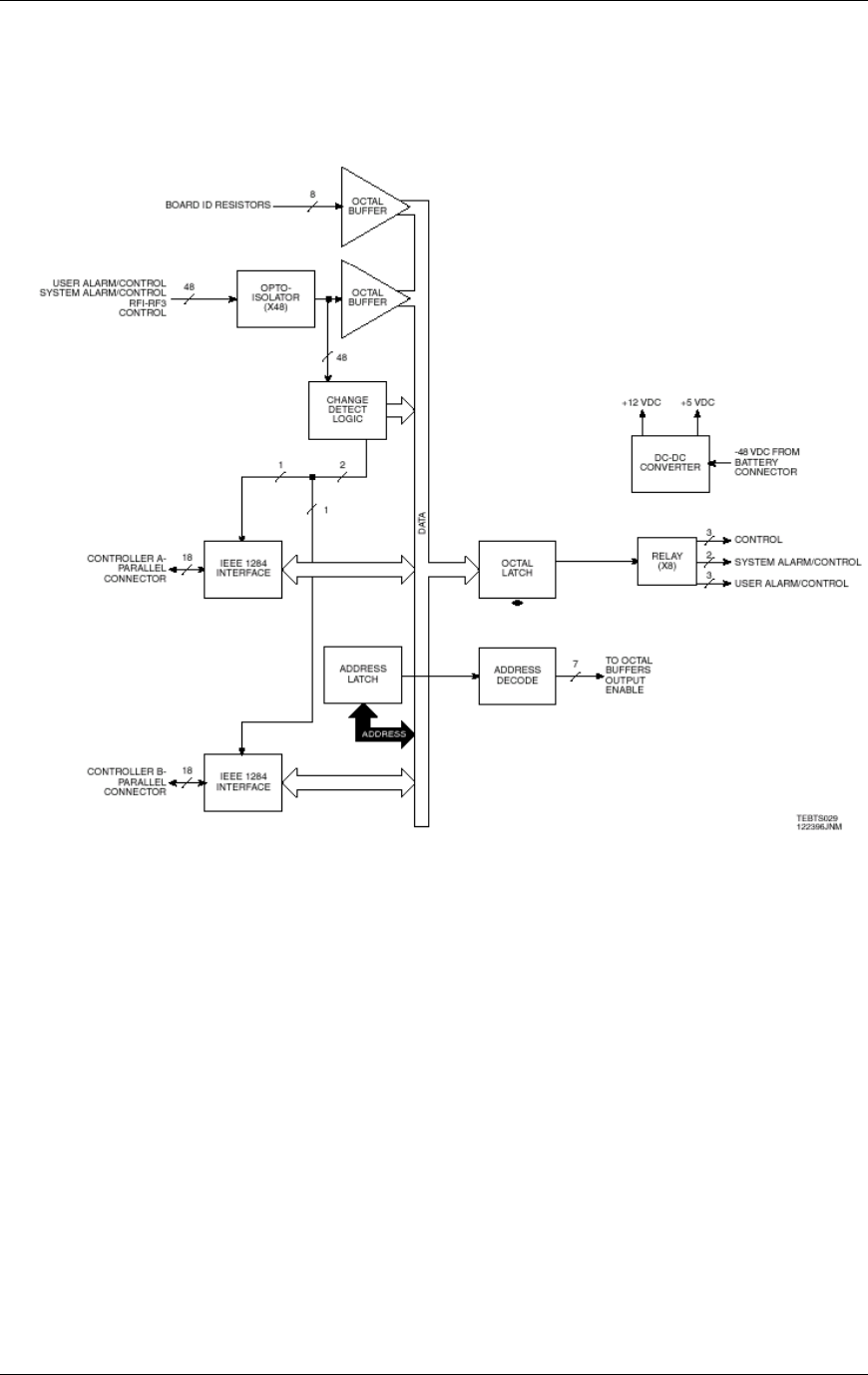
Method of Procedure
System Description
10 RFN_3.1 Beta
connectors. These connectors are cabled to punch blocks to allow simple
installation of the remaining site alarm and control I/O.
Figure 3 Environmental Alarm System functional diagram.
2.1.1.2 GPS Antennas
The Global Positioning System (GPS) antenna provides the timing reference to
the iSC-3. One GPS antenna with a dedicated 50ohm coax is required for each
iSC-3.
Generally, the GPS antennas are to be mounted on a stable platform with a clear
view of the southern horizon and secured access. Horizontal separation of the
antennas is not required for proper operation; however, it is generally required to
increase survivability of the antenna from falling objects.
GPS satellite acquisition and lock can be verified with a handheld GPS receiver
prior to installation. Four satellites should be available.

RadioFrame System
System Description
RFN_3.1 Beta 11
Coax size, 1/2" or 7/8", is determined by the overall length of the coax run (the
distance in feet from the GPS antenna to the top of the equipment rack
containing the iSC-3). The maximum run length for using 50ohm 1/2" coax is
166'. The maximum run length for using 50ohm 7/8" coax is 290'.
2.1.1.3 Channel Service Unit (CSU)
The Channel Service Unit (CSU) provides the T1 connection between the iSC-3
and the telephone company that provides the T1 line. The CSU provides surge
protection to the T1 line and loop-back testing for the telephone company.
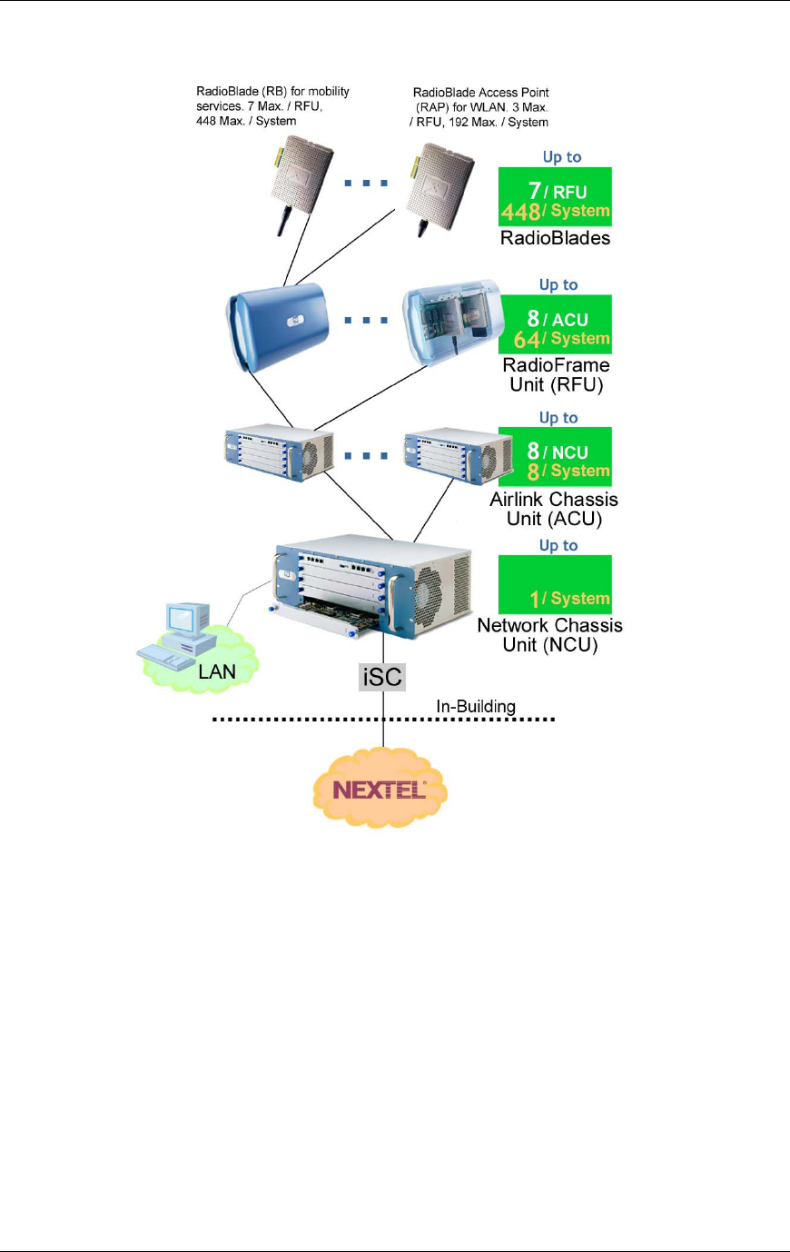
2.1.2 RadioFrame System (RFS)
The RadioFrame System is comprised of several components, which are
connected in a ‘tree’-style architecture (see the following illustration):
• The Network Chassis Unit (NCU) acts as the sole connection point (i.e. the
‘root’) to all ACUs (and RFUs) which ‘branch’ off this ‘root’ chassis. The NCU
also connects to the iSC and the customer LAN.
• Up to eight Airlink Chassis Units (ACUs) connect from the NCU and send
traffic, power and timing to the RFUs over standard CAT 5 wiring.
• Up to 64 RadioFrame Units (RFUs), that house the RadioBlades, provide
access points mounted on walls and ceilings.
• Up to seven iDEN RadioBlades (RBs) can be installed per RFU, and up to
three 802.11b RadioFrame Access Points (RAPs) per RFU; the combined
total is seven RBs/RAPs per RFU. Each iDEN RB and RAP provides a single
RF transceiver that supports iDEN or 802.11b (WLAN).
• Up to two Universal Repeater Units (URUs) can be installed to extend the
distance between components from 328’ (100 meters) to 984’ (300 meters).
• An Ethernet Media Converter is provided to connect the NCU and the iSC-3.
Method of Procedure
System Description
12 RFN_3.1 Beta
Figure 4 The RadioFrame System uses a ‘tree’-style architecture to connect
components.
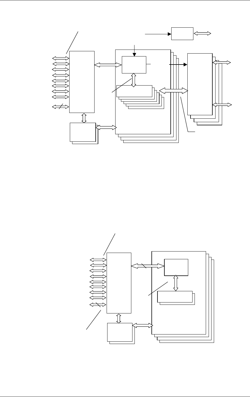
2.1.2.1 Network Chassis Unit (NCU)
The Network Chassis Unit is the main controller of the RFS, providing external
network interfaces and the baseband network processing for the ACUs and
RFUs. The NCU also is the interface between the RFS and the
telecommunications switching entities.
RadioFrame System
System Description
RFN_3.1 Beta 13
Figure 5 NCU functional diagram.
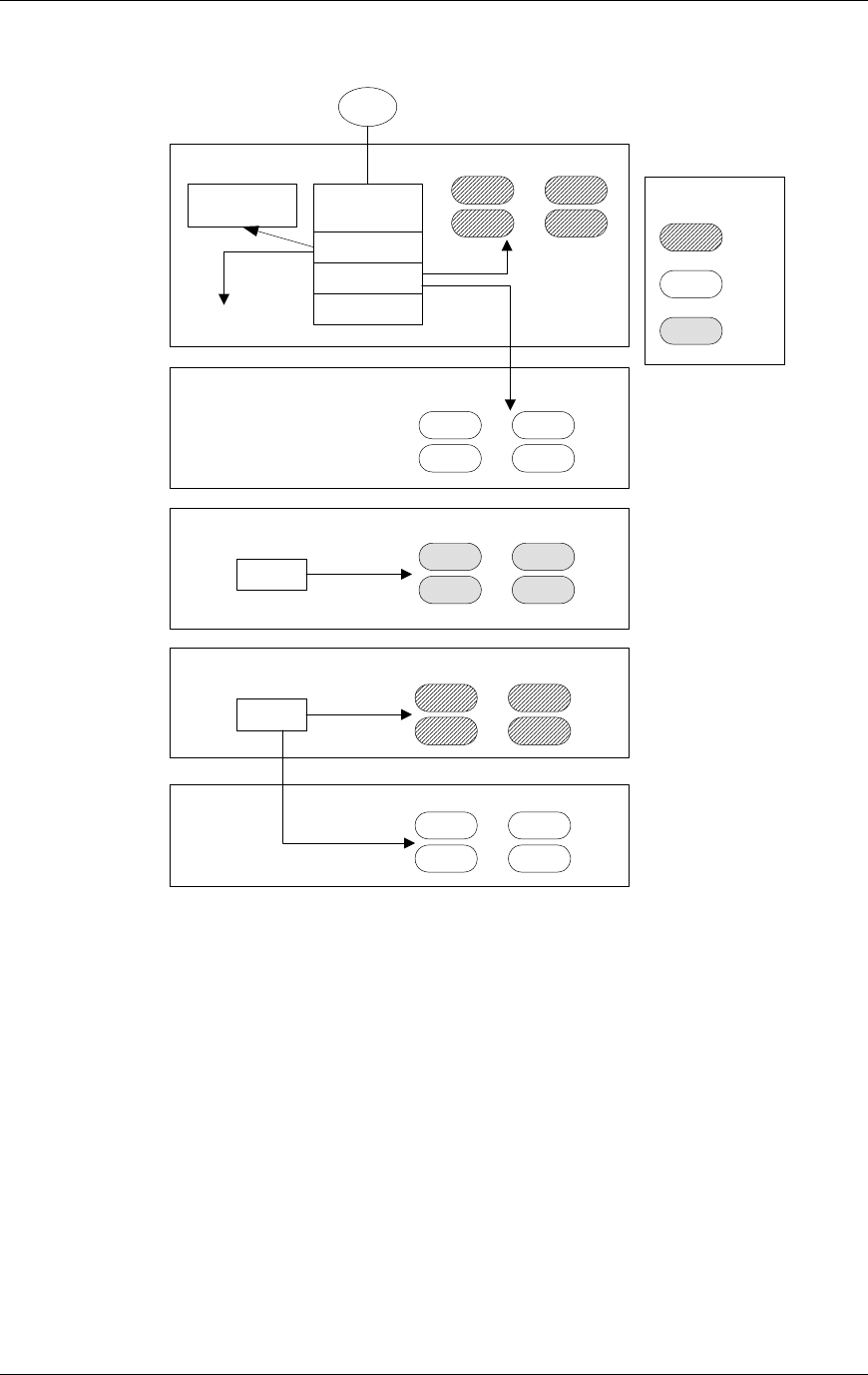
2.1.2.2 Airlink Chassis Unit (ACU)
The Airlink Chassis Unit provides the baseband airlink processing for up to 8
RadioFrame Units, providing a coverage area up to 250,000 square feet. The
ACU is the interface between the RFUs and the Network Chassis Unit, and
provides power, signals, and timing to the RFUs.
Figure 6 ACU functional diagram.
AC-DC
Power
DLC
or
ALC
DLC
or
ALC
DLC
or
ALC
Control &
Encoded Voice
Data
CPU
RLIC
APC (1)
. . .
APC (8)
(Non-fully
configured)
DLC
or
ALC
Host I/F,
Encoded
Voice
Sys Config,
RF Control
Encoded
Voice
IS 41
Messaging
. . .
GU
PCM
DLC
Control &
Config
External
Mode
m
NPC
DSP Plug-In
DSP Plug-In
DSP Plug-In
DSP Plug-In
DSP Plug-In
DSP Plug-In
AC-DC
Power
4 “other”
LAN
Connections
AC-DC
Power
WLAN data, IQ
Samples, Clock,
Control, & Power
CPU
RIC
RFU (1)
. . .
RFN
LAN/WAN/
NCU
RFU (8)
WLAN Data,
Encoded Voice,
Layer 3
Messa
g
in
g
Host I/F,
IQ,
Encoded
Voice
IQ, WLAN
Data, Sys
Config, RF
Control
APC
DSP Plug-In
DSP Plug-In
AC-DC
Power
Method of Procedure
System Description
14 RFN_3.1 Beta
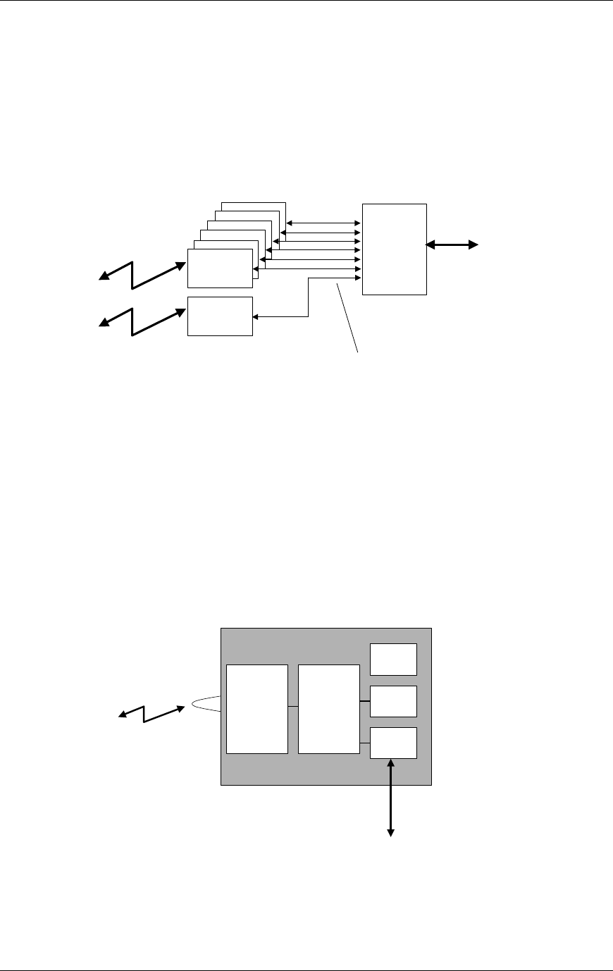
2.1.2.3 RadioFrame Unit (RFU)
The RadioFrame Unit serves as the access interface between signals received
from mobile terminals and the airlink processing performed in the ACU. The RFU
connects to the ACU via a single CAT 5 connection, and receives its power,
signals, and timing from the ACU. Each RFU holds up to 7 RadioBlades in
combination of: a maximum of 6 iDEN RadioBlades, a maximum of 3 RAPs.
Figure 7 RFU functional diagram.
2.1.2.4 iDEN RadioBlade (RadioBlade or RB)
Each iDEN RadioBlade provides a single RF channel transceiver supporting the
iDEN voice standard. Each RadioBlade contains an onboard omnidirectional
antenna and provides a coverage area of approximately 32,000 square feet
(nominal 100’ radius cell). Each RadioBlade inserts into a slot in the RFU.
Figure 8 iDEN RadioBlade functional diagram.
ACU, B
RB (1)
RB (1)
RB (1)
RB (1)
RB (1)
RFU
Backplane
RB (1)
REM
data, clock,
config, control,
timing and
power
Air Interface
Air Interface RF
Section
Digital
Processing
Power
Timing
Ethernet
RFU Backplane
RadioFrame System
System Description
RFN_3.1 Beta 15
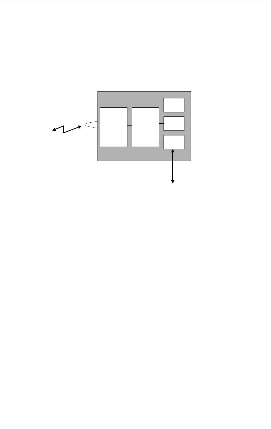
2.1.2.5 802.11b RadioFrame Access Point (RAP)
The 802.11b RadioFrame Access Point (RAP) provides a single RF channel
transceiver supporting the 802.11b (WLAN) standard for wireless data. Each
RAP contains an onboard omnidirectional antenna and provides a coverage area
of approximately 32,000 square feet (nominal 100’ radius cell). Each RAP inserts
into a slot in the RFU.
Figure 9 RadioFrame Access Point (RAP) functional diagram.
2.1.2.6 Universal Repeater Unit (URU)
The Universal Repeater Unit (URU) extends the distance between RFS
components, including the NCU and the iSC, from 328’ (100 meters) to 656’ (200
meters). Up to two URUs can extend the distance to 984’ (300 meters). The unit
repeats the Ethernet signal and timing, and can also supply power to an RFU.
2.1.2.7 Ethernet Media Converter
The Ethernet Media Converter (Allied Telesyn model number AT-MC15) is
installed between the NCU and iSC-3. The MC15 converts signals from twisted
pair cable to thinnet cable, and vice versa, providing seamless connection
between two different media with a 10Base-2 BNC connector. An external 12
Vdc power adapter supplies power to the media converter.
2.1.3 Power Plant
The Power Plant consists of two components: a rectifier and battery plant.
Air Interface RF
Section
Digital
Processing
Power
Timing
Ethernet
RFU Backplane

Method of Procedure
System Description
16 RFN_3.1 Beta
2.1.3.1 Rectifier
The DC power supply is a PECO II 127NHL Low Profile -48 VDC, 20 to 60 Amp
power system, which converts 85 to 265 VAC to -48 VDC using one or two 30
Amp Modular Rectifiers (20 Amp output with a 115 VAC @ 15 Amp input circuit).
The rectifiers can be paralleled for increased power and redundancy and are
capable of "Hot Insertion".
The Low Profile plant is self-contained and includes DC Distribution plus a
system Simple Controller. Each rectifier module contains a micro-controller,
which monitors internal temperatures, voltages and currents, and makes
adjustments to reliably deliver maximum output power.
Rectifier modules digitally exchange status data with the Simple Controller via a
data bus. The system Simple Controller evaluates all data, displays rectifier and
system parameters, compensates the battery voltage for temperature, extends
alarms and provides access to changing setpoints and system status. Monitors
for battery string temperature and midpoint are optional. Connections have been
connectorized to facilitate installation.
Basic Design
Basic features of all 127NHL plant include Distribution, a Distribution Monitor and
a Simple Controller. The Distribution Monitor provides fuse alarm inputs, plant
voltage and current monitoring, low voltage disconnect control, and battery
monitoring. With the optional Battery Temperature Compensation kits, the
127NHL plant can monitor up to two strings of batteries and adjust rectifier output
voltage to compensate for battery temperature, reducing the potential for VLRA
battery thermal runaway and potentially extend battery life.
The plant Simple Controller is the user interface and collects and reports
monitored signals and alarms. A local display provides a visual indication of plant
status, alarm conditions and plant settings as well as status of each individual
rectifier. The user interface supports the adjustment of setpoints and changing
plant status (i.e. Enter Equalize mode).The controller provides two Form C
contacts for PMN (Plant Minor)and PMJ (Plant Major) alarms plus a Maintenance
Port for a PC interface. PC Interface software and cabling kit is an available
option.
For more information, refer to the product specification information provided by
Peco II, Inc., the rectifier manufacturer: PEC 127NHL.
2.1.3.2 Battery Plant
The main equipment cabinet relies on an 8-hour backup system. The equipment
cabinet requires the following components that will define the Battery Plant.
• 2 Strings of -48 Volts 105 Amp Capacity Battery, such as Deka or Power
Batteries (or other approved vendors)
RadioFrame System
System Description
RFN_3.1 Beta 17
• 2 Standard Battery Shelves (19”)
• 2 Battery Manual Disconnects
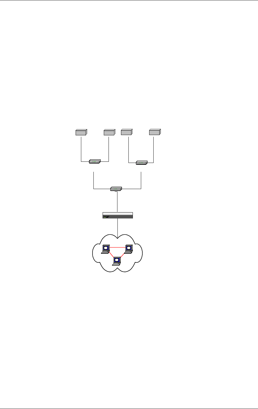
2.1.4 Local Area Network (LAN)
The RadioFrame System plugs into the customer’s local area network (LAN)
using a standard Ethernet connection over CAT 5 wiring. The customer’s LAN
may include a variety of equipment, including switches, routers, and gateways.
The RFS connects to the LAN via Port 2 on the front of the NCU. The RAPs
installed in the RFUs support the LAN.
Figure 10 RFS and customer LAN functional diagram.
In the above diagram, an optional “gateway” device is shown between the
customer LAN and the RFS to provide a point of control, thus isolating the RFS
from the customer’s LAN. The gateway may be used to perform inter-network
routing and access control, permitting only authorized users access to the
customer LAN via the RFS. It may also perform service accounting and user
mobility functions.
NOTE: Though not required, the use of a gateway device is strongly
recommended, particularly for use as an access control mechanism to prevent
Customer LAN
NCU
ACU
RFUs
ACU
RFUs
Gateway

Method of Procedure
System Description
18 RFN_3.1 Beta
unauthorized access to the customer LAN. In addition, while a router between
the RFS and the customer LAN is not required, it is highly recommended that a
combination router and security gateway be used.
The RFN implementation of 802.11b provides a transparent MAC layer bridging
function between the RFS and the customer’s LAN. No layer 3 (IP) protocol
routing is required for operation.
The NCU contains a card that is assigned a fixed address during installation.
Once the NCU has been configured, the NCU will automatically assign IP
addresses to each network element in the RFS.
2.2 Physical Relationships
The RadioFrame System is laid out as follows:
• Main rack: Located in a Telco closet, the main rack houses the entire iDEN
Interface and Power Plant, along with the NCU and one ACU of the
RadioFrame System.
• Remote ACUs: Up to seven additional ACUs can be connected to the NCU.
The remote ACUs are installed in closets or Telco rooms throughout the
building to support additional RFUs.
• RFUs: Up to 8 RFUs per ACU are installed on walls or on or above ceilings
throughout the building to provide coverage for the iDEN/802.11b RFS; RFUs
house the iDEN RadioBlades RAPs.
• LAN: Customer equipment located in a customer-defined area.
The following illustration depicts a typical RadioFrame Networks iDEN/802.11
solution. The main rack is located on Floor 4 housing the iDEN Interface, Power
Plant, and the NCU and one ACU of the RFS. The Customer LAN equipment is
also located on Floor 4.
Remote ACUs are located on Floors 1 and 2, with each ACU supporting up to
eight RFUs. The ACU located on Floor 1 also supports RFUs in the parking level.
RFUs on each floor of the building, 1, 2, 3, 4 and the parking level, support one
of three sectors. RFUs on Floors 1 and 4 support sector 1. RFUs in the parking
level and on floor 3 support sector 2. RFUs on Floor 2 support sector 3.
RadioFrame System
System Description
RFN_3.1 Beta 19
Figure 11 A typical RadioFrame System iDEN/802.11b installation.
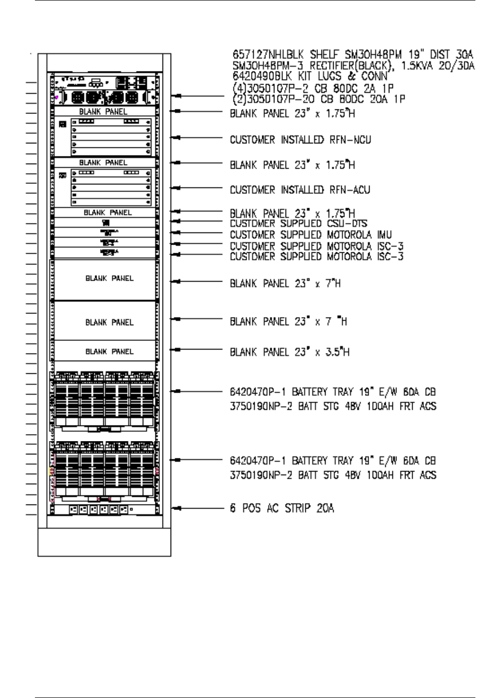
2.2.1 Main Rack
The following illustration shows a typical 19” EIA standard rack diagram for a
RadioFrame System installation. This main rack includes:
• the entire iDEN interface: two iSC-3s, an EAS, GPS Antennas and a CSU
• the NCU and one ACU of the RadioFrame System
• the entire Power Plant: 2 rectifiers and 8 battery backup units
NCU
ACU
ACU
Floor 4
GPS
To Remote ACUs
Floor 3
Sector 1
Legend
Sector 3
Sector 2
Floor 2
ACU
Floor 1
Parking
Level
iDEN
Interface
Power Plant
RFU 4
RFU 2
RFU 3
RFU 1
RFU 4
RFU 2
RFU 3
RFU 1
RFU 4
RFU 2
RFU 3
RFU 1
RFU 4
RFU 2
RFU 3
RFU 1
RFU 4
RFU 2
RFU 3
RFU 1
Customer
LAN
Main Rack
Method of Procedure
System Description
20 RFN_3.1 Beta
Figure 12 The main rack houses the iDEN interface, the NCU and one ACU of the
RadioFrame System, and the Power Plant.
RadioFrame System
System Description
RFN_3.1 Beta 21
2.2.2 Remote ACUs
Remote ACUs are located in Telco rooms or other closets throughout the
building mounted in 19” EIA-standard compliant racks or equivalent. The racks
for remote ACUs may be either floor or wall-mounted racks. Any other method
used to mount the remote ACU is not approved, and could void the warranty on
the product and other components in the RFS.
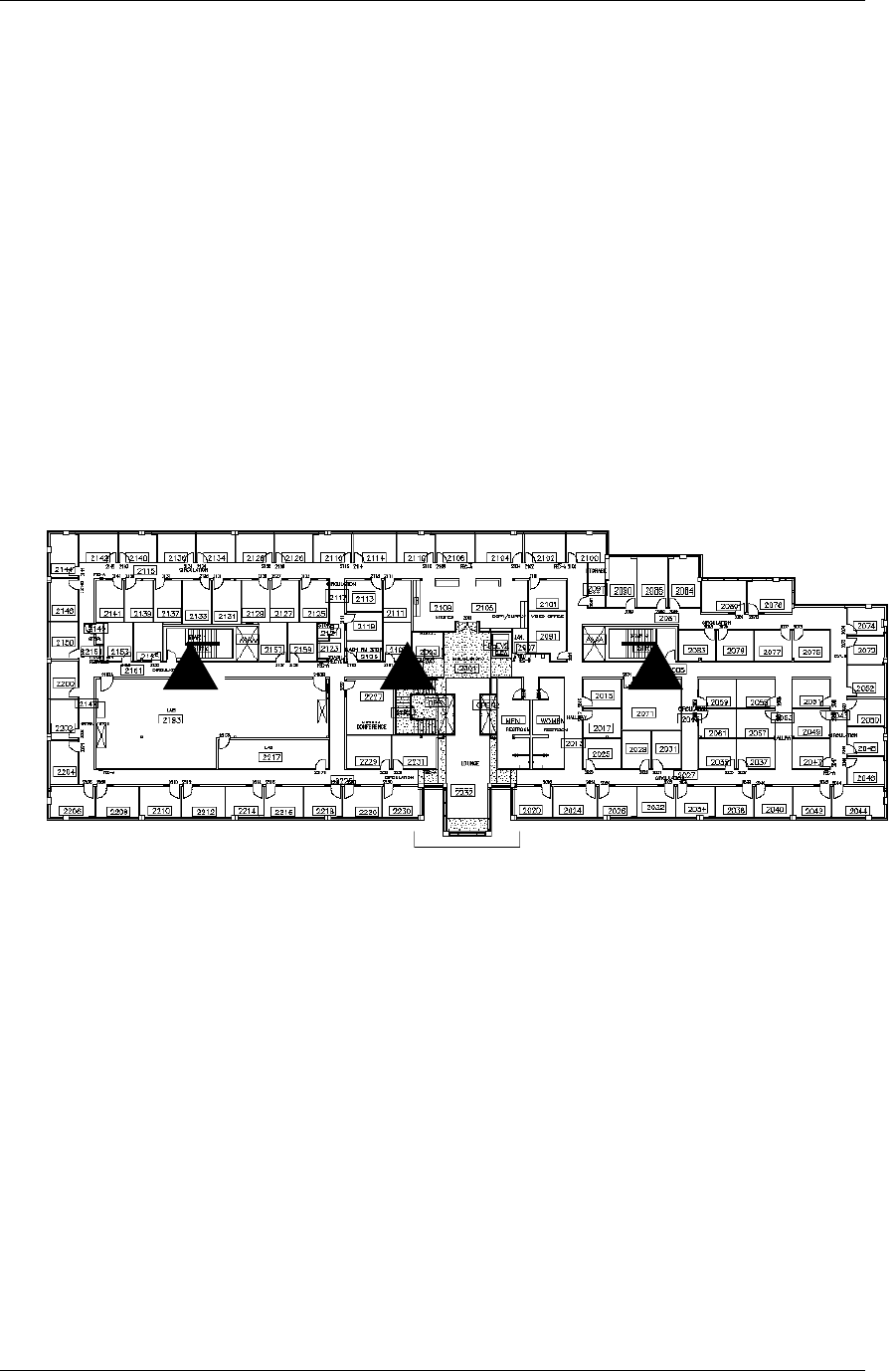
2.2.3 RFUs
RFUs are located throughout the building to provide coverage for specific areas.
RFUs are typically mounted on or above the ceiling, or on a wall. The following
illustration depicts typical RFU locations using a simple floor plan. Three RFUs,
denoted by triangles, are located along the central hallway providing coverage to
each portion of the floor. Antenna coverage for each RFU is a 100-foot radius
(30.3 meters) or approximately 32,000 square feet (2,920 square meters).
Figure 13 RFUs are located throughout the building to provide coverage.
2.2.3.1 RadioBlades and RAPS
The number and combination of RadioBlades and RAPs to be installed in each
RFU is driven by the coverage and capacity requirements of that particular
portion of the building. A maximum of six iDEN RadioBlades can be installed in
each RFU. A maximum of three RAPs can be installed in each RFU. The
combined total of iDEN RBs and RAPs is seven per RFU. Each RadioBlade is
supplied with an antenna that must be installed vertically and pointed down
towards the ground.

Method of Procedure
System Description
22 RFN_3.1 Beta
iDEN RB 802.11b RAP RFU
Figure 14 RadioBlade and RAP antennas must point straight down to the ground.
2.2.4 LAN
The customer LAN equipment can be located anywhere within the building. An
Ethernet cable connection must available from the LAN to the main rack for
connection to the NCU.

RadioFrame System
Pre-Installation
RFN_3.1 Beta 23
3 Pre-Installation
This section provides pre-installation information for a RadioFrame System at a
RFN customer site. A pre-installation site review and evaluation helps prevent
potential equipment installation problems. Consider every subject discussed in
this section before installing the iDEN/802.11b RFS.
3.1 Receipt of Equipment
The main rack is provided pre-installed with the following equipment:
• Rectifier, PECO II
• NCU (Network Chassis Unit), RadioFrame Networks
• ACU (Airlink Chassis Unit), RadioFrame Networks
• CSU (Channel Service Unit), DTS
• EAS (Environmental Alarm System), Motorola
• two iSC-3s (integrated Site Controllers), Motorola
• two battery trays, 2 x 100 amp batteries
All other equipment is RadioFrame Networks equipment and is shipped as
follows: each RFU, remote ACU, and URU is shipped in its own box. The iDEN
RadioBlades and RAPs are shipped several to a box and individually wrapped in
antistatic packaging. Unpack each unit only at the time of installation—leave
items in their shipping containers until ready for use. Unpacking instructions are
contained inside each shipping container.
3.1.1 Equipment Inspection
Inspect the RadioFrame Networks iDEN solution equipment immediately upon
receipt. If obvious damage has occurred to shipping containers before
unpacking, contact the shipping agent. Ask that a representative of the shipping
company be present while the equipment is unpacked. Observe guidelines for
safe handling of electrostatic sensitive devices or equipment to prevent damage
due to electrostatic discharge. A conductive wrist strap is provided with each
RFU and should always be worn when handling any electrical component,
including iDEN RadioBlades.
Check for the following:
• loose or damaged equipment in the pre-installed main rack
• dents, scratches, or other damage on all sides of each component
• physical damage to iDEN RadioBlade or RAP antennas or connectors

Method of Procedure
Pre-Installation
24 RFN_3.1 Beta
If any equipment is damaged, contact the shipping company immediately, then
your RFN customer representative.
3.1.2 Equipment Inventory
Check all the RadioFrame System equipment against the itemized packing list to
ensure receipt of all equipment. If available, check the sales order with the
packing list to account for all equipment ordered. Contact your RFN customer
representative to report missing items and for additional information.
3.1.3 RadioFrame Networks Documents Shipped with the RFS
The following RadioFrame Networks documents are shipped with the
RadioFrame System.
Document Title RFN Part Number
RFS Installation Guide 981-6200-00
RFS Operators Guide 981-6300-00
Unpack the Box: NCU 981-5000-00
Unpack the Box: ACU 981-5100-00
Unpack the Box: RFU 981-5200-00
Unpack the Box: URU 981-5300-00
Unpack the Box: Ethernet Media Converter 981-5020-00
RFU Mounting Template: Ceiling 981-1010-00
RFU Mounting Template: Wall 981-1020-00
Universal Repeater Unit Mounting Template 981-0641-00
Product Specification: Chassis Unit 981-0500-00
Product Specification: RFU 981-1000-00
Product Specification: URU 981-0640-00
Product Specification: Ethernet Media Converter 981-0660-00
Product Specification: iDEN RadioBlade 981-0620-00
Product Specification: 802.11b RadioFrame Access Point 981-0531-00

RadioFrame System
Pre-Installation
RFN_3.1 Beta 25
3.2 Site Planning
Licensing and the availability of space help to determine a site selection. On a
RFN customer owned or controlled site, field engineering and program
management will plan the system and site layouts. Planning helps prevent
potential on-site and off-site interference from other RF systems. Site layouts
should always be planned to minimize inter-cabling lengths between RF
equipment.
3.2.1 Site Considerations
3.2.1.1 Main Rack
The site for the main rack should not contain windows and must be able to resist
extreme weather conditions. It should be designed to meet the requirements of
the American National Standards, Building Code Requirements for Minimum
Design Loads in Buildings and Other Structures. RFN recommends the following
considerations when selecting a site:
• A minimum floor space of at least 42 square feet is recommended to allow
enough space for front and rear access to the main rack.
• The minimum ceiling height of at least 8’6” above a finished floor is required
to allow enough space for the height of the main rack and cable access at the
top of the cabinet.
• The ceiling structure should be able to support a cable tray assembly for
routing the inter-cabinet cabling and other site cabling. The cable tray
assembly is mounted to the site ceiling and walls per site plan and should be
at least 7’6” from the site floor to allow for the height of the main rack.
• The minimum door dimensions should be at least 3’ wide and 6’8” high.
• All exterior doors should have tamper proof locks installed for security
purposes.
• The interior site environment should be maintained at a constant 78° F
(25.6° C). The site should be capable of maintaining this temperature in an
outside ambient temperature range of -10 to +105° F (-23.4 to +40.6° C).
RadioFrame Networks iDEN solution equipment is not approved or
recommended for outdoor use.
• Proper surge protection is required for all antennas and power inputs to
prevent potential damage to site equipment.
• The site floor should be level to within 1/8” and able to support the weight of
site equipment.

Method of Procedure
Pre-Installation
26 RFN_3.1 Beta
3.2.1.2 Remote ACUs
Remote ACUs are located in Telco rooms or other closets throughout the
building. Any such location must be free of dust, wind, salt and liquids. All other
operating environment specifications that apply to an ACU in the main rack also
apply to a remote ACU.
Remote ACUs must be mounted in a 19” EIA-standard compliant rack or
equivalent. The racks for remote ACUs must be either floor or wall mounted. Any
other mounting method is not approved, and could void the warranty on the
product and other components in the RFS.
The number and location of remote ACUs is determined by the number of RFUs
required to provide coverage for the iDEN/802.11b RFS.
3.2.1.3 RFUs
The RadioFrame System is designed to simplify site planning. The RFS
intentionally limits antenna coverage to a 100-foot radius (30.3 meters) or
approximately 32,000 square feet (2,920 square meters). To determine the
number of RFUs required to provide coverage, divide the desired area’s square
footage by the RFS minimum coverage area (32,000). This determines the
minimum number of RFUs.
The capacity requirements of the site determine the number of iDEN
RadioBlades and 802.11b RAPs that will be required. RFUs are mounted so that
the antennas of the installed iDEN RadioBlades and 802.11b RAPs point to the
ground. This orientation of the antennas must not be changed.
The number and exact location of RFUs is determined by capacity and coverage
requirements, as well as site considerations, such as mounting considerations,
interior structures, and interference from macro systems. For more information
on site planning considerations, refer to the RFN document, RF Planning Guide
for RadioFrame iDEN Systems (P/N 990-1001-00).
3.2.1.4 LAN
Connecting the RFS to the customer LAN requires only a single Ethernet cable
from the NCU in the main rack to the customer’s LAN equipment (gateway,
switch, router etc.). No other site considerations are required.
3.3 Main Rack and Supporting Hardware
Most communications equipment is mounted into standard 19” EIA racks or
enclosed cabinets. Follow the rack and/or equipment manufacturer's instructions
when installing equipment into racks or cabinets.
For example:
• All supplied bracing hardware shall be properly utilized.

RadioFrame System
Pre-Installation
RFN_3.1 Beta 27
• Proper hardware shall be used to secure equipment.
• Convected heat transfer from one piece of equipment rack to another shall be
considered. Heat baffles may be required.
3.3.1 Mounting
The front panels of the NCU, ACU, iSC-3s, CSU, PDU and EAS are 19” wide to
allow for installation into 19” wide cabinets. All of this equipment is typically
installed into a 19” wide cabinet prior to shipment to the site. For rack installation
instructions for the NCU and ACU, see Appendix C NCU and ACU Main Rack
Installation.
3.3.1.1 Plumb and Squareness
Equipment shall be level and plumb. Equipment level shall be tested on a known
flat surface in at least two directions to verify accuracy.
Equipment shall be parallel or perpendicular to the surrounding walls and
adjacent installed equipment.
3.3.1.2 Anchoring
Anchoring is the mechanical fastening of the communications equipment to
suitable locations using hardware acceptable for the application.
Although every installation is unique, certain methods for anchoring shall be
adhered to for all installations. Typically, at least four anchor points shall be used
on each item of equipment mounted to the floor. The only exception is when the
equipment manufacturer supplies other than four mounting points.
3.3.1.3 Mounting on Concrete Floors
Equipment racks or cabinets should be positioned and anchored to the floor
using preferred mounting methods. In general, observe the following:
• An anchor specifically designed for concrete shall be used. The preferred
method for anchoring racks, or other ancillary equipment to concrete floors is
to use flush-mount expansion anchors properly sized for the application.
Flush mount expansion anchors do not extend above the surface of the floor
and provide an easy bolt down. They also provide the required pullout and
shear strength. If at a later time equipment needs to be moved, flush mount
expansion anchors do not get in the way.
NOTE: Unless an isolating mounting scheme is used (refer to section 3.3.1.4
Isolated Mounting, next in this section), ensure that no anchors come in
contact with reinforcing rods or wire mesh buried in the concrete; the rack
shall be electrically isolated from any other equipment or materials at the site.

Method of Procedure
Pre-Installation
28 RFN_3.1 Beta
• In applications where flush-mount expansion anchors are not preferred or
acceptable, then wedge-type stud anchors may be used.
• All concrete anchors shall be zinc-plated carbon steel for standard
applications, galvanized steel for mildly humid or corrosive environments, and
yellow zinc or stainless steel for humid, highly corrosive, or acidic
environments. Minimum bolt diameter shall be 10 mm (0.375 in.) with 12 mm
(0.5 in.) preferred. Anchor embedment depth should be at least 76 mm (3 in.)
to provide good tensile and shear strength. Follow manufacturer's instructions
for depth reduction when rebar is encountered. A heavy-duty washer should
be part of the anchor assembly to ensure the equipment is secure.
3.3.1.4 Isolated Mounting
Isolated mounting is recommended to prevent a second electrical path to ground
through the concrete floor, and is required for the installation of certain
equipment. In these cases expansion anchors are inserted into the concrete
floor. However, isolation of the equipment rack is ensured using an insulating
plate and hardware. If the installation is in an earthquake zone, additional
anchors are used.
NOTE: Motorola equipment frames are always required to use, and are shipped
with, isolating washer and bolt assemblies, and have separate insulating
mounting plates. Refer to the Motorola document 68P09226A18 Frame Mounting
Guide for more information.
3.3.1.5 Mounting on Wood or Fiberglass Floors
Appropriately sized lag bolts shall be used for mounting on wood or fiberglass
floors. If the underside is accessible and the floor stability is questionable, then
thru-bolting may be desirable.
RFN recommends mounting non-racked ancillary equipment on a "C-channel"
type of mounting track where possible. This provides for easy cleaning and some
isolation in the case of standing water. Another benefit of installing non-rack
mounted equipment off the floor is that the weight is distributed across the floor.
In these cases, C-channel type mounting provides multiple floor anchor points
where the equipment provides only four to six anchor points.
When mounting racks to raised computer floors, 0.5 in. (13 mm) minimum
diameter allthread rod and flush-mount expansion anchors shall be used to
anchor to the concrete subfloor. When mounting consoles to a raised floor,
0.375 in. (10 mm) minimum allthread rod and hardware shall be used for
anchoring. Mounting arrangement shall be in accordance with mounting kit
manufacturer's instructions.

RadioFrame System
Pre-Installation
RFN_3.1 Beta 29
3.3.1.6 Anchoring Equipment to Raised Floors
The anchoring of overhead and wall-mounted devices present a number of
considerations. Placement is very important; if equipment is bolted to a wall that
is on an aisle, the aisle may be unacceptably narrowed with the danger of injury
to personnel. Also, the serviceability of the equipment being mounted to adjacent
equipment may be inhibited.
Overhead applications generally include coax cabling, cable runways, and
mounts for earthquake bracing. All overhead applications should keep in mind
loading of overhead surfaces. Care must be exercised when deciding how much
can be held by the ceiling without some sort of building foundation support. In the
case of earthquake bracing equipment, cable runways can be secured overhead
then affixed to the equipment racks providing acceptable foundation support.
When anchoring cable runways to ceilings or walls, the manufacturer-supplied
support hardware shall be used.
Anchors used in overhead applications vary depending on the ceiling structure as
follows:
• For concrete and wood ceilings, the same principles discussed in floor
anchoring apply.
• For an exposed steel l-Beam ceiling, many cable runway manufacturers
make beam clamps for C-channel or threaded drop rods.
• For corrugated steel ceilings, C-channel tracks can be affixed to the ceiling
using properly sized lag bolts. The C-channel will span the corrugated steel
and provide multiple anchor points.
For drywall or plasterboard ceilings, special considerations are required:
• If the drywall is on steel or wooden roof joists, locate and tap into the roof joist
with lag bolts.
• C-channel mounting can be used.
• An alternative to C-channel mounting is using large toggle or molly wings with
hex head tap bolts.
NOTE: Make certain joists are properly located before drilling into drywall.
3.3.1.7 Seismic Anchoring
Seismic anchors are designed, tested, and specified for seismic zones 3 and 4.
Seismic anchors enhance the stability of equipment due to the special
characteristics specifically suited to the dynamic and cyclic loading effects
experienced during earthquake events. As such, anchors shall be used that are
manufactured to particular specifications that make them the most resistant to
the effects of dynamic and cyclic loading effects.

Method of Procedure
Pre-Installation
30 RFN_3.1 Beta
Selected anchors shall meet standards set forth in NESS (Network Equipment
Building Systems) TR-64 and ASTM (American Society For Testing and
Materials) 488-90 for earthquake compliance. This testing evaluates anchors for
bolt failure from shearing and from pullout or slippage. Compliance with these
standards requires that the anchor not allow a standard top heavy 7 ft. (2.2 m)
rack to have a deflection greater than 3 in. (7.6 cm) at the top of the frame. This
compliance will also adhere to Bellcore Technical Specifications AU-434 for
earthquake concrete expansion anchors.
Anchor selection criteria shall comply with all general requirements for standard
concrete anchors plus meet the above seismic requirements. All seismic
anchoring shall be enhanced with top cabinet or rack bracing.
Seismic Considerations
All RadioFrame Networks equipment is seismically rated to withstand vibrations
of a Level 3 earthquake. The property owner is responsible for any damage to
RFN equipment due to building or rack structures that are not rated to withstand
vibrations of a Level 3 earthquake, or not secured to withstand vibrations of a
Zone 4 earthquake.
Site protection from earthquakes may be required in certain areas. Typically, this
would be an area having historical data indicating a Moment Magnitude rating of
3 or 4. Note that areas other than historically prone areas may need
consideration. Obviously, addressing such concerns results in increased costs of
equipment installation.
A certified architect specializing in earthquake-resistant installation shall be
consulted for seismic designs and recommendations in areas where the potential
loss of the site may outweigh associated costs of earthquake-resistant design. In
the United States, it is recommended to consult the US Geological Survey for
more information regarding earthquake probability and historical data for various
areas. In other areas, similar consultation should be done.
• The US Geological Survey information can be accessed at:
http://geohazards.cr.usgs.gov
• Seismic maps are available at:
http: //www.neic.cr.usgs.gov
Earthquake-resistant design should be contracted to a firm specializing in such
work. However, the following general considerations need to be observed and
factored into a seismic design program:
• Equipment shall not be secured to both the shelter walls and floors, since
dissimilar movement between these surfaces is likely in an earthquake.
• Mounting should provide for some "sway" in the overall equipment mounting,
thereby absorbing the energy of an earthquake. This is typically
accomplished by rigid mounting of racked equipment or cabinets at the base,
while semi-rigidly attaching the rack top using 1/8 in (3.2 cm) diameter steel

RadioFrame System
Pre-Installation
RFN_3.1 Beta 31
braided wire rope. Wire rope anchors are then secured to ceilings joists. The
benefit of this type of installation is that racks are allowed to sway within limits
but can't fall over.
• Cabinet designs with wide footprints can be used to help prevent cabinets
from tipping over.
• Columns of cabinets stacked and bolted back-to-back present a very stable
and wide footprint. The bottom cabinets shall still, however, be bolted to the
floor for complete security.
• Some cabinets can be outfitted with outrigger-type support legs to prevent tip-
over. These outriggers alone do not provide adequate earthquake protection,
but are typically adequate if the cabinet is bolted to the floor.
NOTE: If a rack is seismic rated, any add-on aftermarket equipment or
equipment that is not seismic rated will render the overall package as not
being seismic tested and certified as a unit. Therefore, the unit would no
longer be considered as seismic rated.
• When bolting down to computer floor, be sure to anchor all the way to the
subfloor.
• Columns of cabinets must be supported, though not rigidly. Rigid mounting
will result in extreme vibration and resultant mechanical failure during an
earthquake. Semi-rigid mounting is preferred. Semi-rigid bracing is defined as
bracing which allows a measurable amount of movement.
• Some computer floors lose mechanical integrity if several panels are
simultaneously removed. This could lead to equipment floor collapse during
at earthquake. The flooring manufacturer shall be consulted for floor removal
procedures.
• Equipment shall be stabilized by a top support. This is critical in preventing a
column of equipment from toppling, causing injury to personnel. The footings
cabinet columns and racks shall be bolted to the floor as appropriate, using
concrete anchors. Sometimes the cabinet columns are placed on C-channel
tract or wooden pedestals.
• Cables and transmission lines should not be installed rigidly, and without
strain relief. Make broad service loops.
• Lighting fixtures should be prevented from swaying by the addition of one or
more guy wires. A fluorescent lighting fixture in particular, can be very
dangerous if allowed to swing against a wall or equipment racks, shattering
and spraying broken glass below. Fluorescent lighting fixtures shall have
protective lenses or protective plastic sleeves that cover the fluorescent tube,
preventing broken glass from falling on occupants.
• Storage cabinets shall be secured to the wall to prevent upset. Storage
cabinets shall also have closable, secured doors to prevent contents from
spilling during an earthquake.

Method of Procedure
Pre-Installation
32 RFN_3.1 Beta
• Ladders and other large objects shall be secured to a wall or removed from
the equipment room when not in use. These items have been known to fall
into “live” equipment during earthquakes.
3.3.2 Clearances
Proper spacing of equipment is essential for efficient use of the room area, ease
of maintenance, and safety of personnel. The following specifications have been
established to meet the National Fire Protection Associations (NFPA) Code, and
the American Society of Heating, Refrigerating, and Air Conditioning Engineers
(ASHRAE) standards. Any local regulations, as applicable, shall also be adhered
to.
• To provide adequate working space, a 576 sq. in. (0.37 m2) footprint (as
measured from facing equipment surfaces) shall be used for combining
equipment.
NOTE: Local codes may require additional clearance. In such cases, the
local code shall prevail.
• 36 in. (91 cm) front and side aisles shall be maintained around electrical
panel boards (NPPA 70, Article 110-26).
• 36 to 48 in. (91 to 123 cm) front, side, and (where applicable) rear aisles are
required for servicing equipment.
• 36 in. (91 cm) aisle shall be maintained in front of all equipment.
• 36 in. (91 cm) aisle shall be maintained between at least one end of an
equipment row and building wall or other obstruction; longer aisles may
require additional access breaks. Larger aisles and additional access breaks
in a row may be require as the row becomes longer, such that a fire in the
aisle does not prevent egress. Comply with any codes regarding fire egress
specifications.
• Ingress and egress to equipment rooms shall conform to NFPA 70, Article
111 and local building and fire codes.
• In US installations where a facility is to be normally occupied, American with
Disabilities Act (ADA) shall be complied with. Some general requirements of
ADA are 91.5 cm (36 in.) wide doors, ramps and safety rails, 36 in. (91.5 cm)
can turn around clearance for wheelchairs, and specific placement of
telephones, fire extinguishers, light switches, etc.
NOTE: ADA compliance in architectural plans may be required in obtaining a
construction permit in some localities.
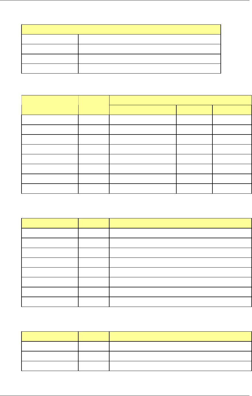
RadioFrame System
Pre-Installation
RFN_3.1 Beta 33
Main Rack Clearances
BACK 36”
FRONT 36”
SIDES 36”
ABOVE 36”
Equipment Dimensions System Unit
Width Depth Height
RadioFrame System NCU 19” 13” 7”
ACU 19” 13” 7”
iDEN Interface iSC-3 (1) 17” 9” 1.75”
iSC-3 (2) 17” 9” 1.75”
EAS 17” 15” 1.75”
CSU 19” 12.5” 1.75”
Power Plant Rectifier 19” 12.5” 5.25”
Battery 19” 20” 14”
3.3.2.1 Back
System Unit Back Clearance
RadioFrame System NCU 7”
ACU 7”
iDEN Interface iSC-3 (1) 7”
iSC-3 (2) 7”
EAS 7”
CSU 7”
Power Plant Rectifier 7”
Battery 7”
3.3.2.2 Front
System Unit Front Clearance
RadioFrame System NCU 12”
ACU 12”
iDEN Interface iSC-3 (1) 12”
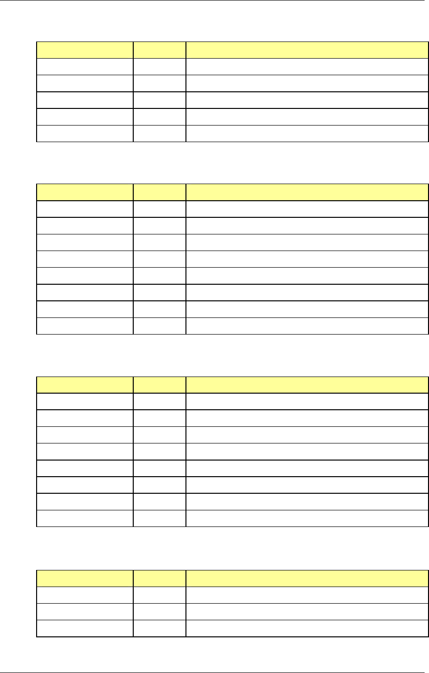
Method of Procedure
Pre-Installation
34 RFN_3.1 Beta
System Unit Front Clearance
iSC-3 (2) 12”
EAS 12”
CSU 12”
Power Plant Rectifier 12”
Battery 12”
3.3.2.3 Sides
System Unit Side Clearance
RadioFrame System NCU right side facing 2”; left side 0”
ACU right side facing 2”; left side 0”
iDEN Interface iSC-3 (1) right side facing 2” / left side 2”
iSC-3 (2) right side facing 2” / left side 2”
EAS right side facing 2” / left side 2”
CSU right side facing 2” / left side 2”
Power Plant Rectifier right side facing 2” / left side 2”
Battery right side facing 2” / left side 2”
3.3.2.4 Above
System Unit Above Clearance
RadioFrame System NCU 0”
ACU 0”
iDEN Interface iSC-3 (1) 0”
iSC-3 (2) 0”
EAS 0”
CSU 0”
Power Plant Rectifier 0”
Battery 0”
3.3.3 Weight
System Unit Weight
RadioFrame System NCU 27 lbs
ACU 27 lbs
iDEN Interface iSC-3 (1)
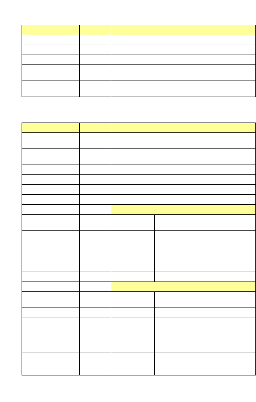
RadioFrame System
Pre-Installation
RFN_3.1 Beta 35
System Unit Weight
iSC-3 (2)
EAS
CSU
Power Plant Rectifier 72 lbs
(Power Plant 58 lbs) + (two Rectifiers at 7 lbs ea.)
Battery 600 lbs
(eight batteries at 75 lbs each)
3.3.4 Power
System Unit Power
RadioFrame System NCU 100-240 Volts AC, 47-63 Hz, 8-3.5A, or
Negative 52.5 ±.5 Volts DC, 11A
ACU
100-240 Volts AC, 47-63 Hz, 8-3.5A, or
Negative 52.5 ±.5 Volts DC, 11A
iDEN Interface iSC-3 (1) Negative 40-60 Volts DC; 1.5 A
iSC-3 (2) Negative 40-60 Volts DC; 1.5 A
EAS
Negative 40-60 Volts DC
CSU
Negative 40 Volts DC
Power Plant Rectifier Input
Voltage
85 to 265 VAC (continuous)
45 to 70 Hz
Current
12 Amp maximum
The rectifier’s micro-controller adjusts
the output current to limit the input
current to allow each rectifier to be
plugged into a standard 115/230 VAC @
15 Amp IEC outlet.
Power Factor >90% for 20% to 100% loads
Output
Voltage
50.00 to 60.00 VDC
52.5 VDC Factory Set (default)
Regulation
± 1.0% (includes output o-ring diode)
Overvoltage
50.00 to 60.00 VDC
57.00 VDC Factory Set (default)
RED [FAIL] LED indication and shuts
down rectifier providing output
current.
Noise
<32 dBmC (voice frequency)
<100 millivolts-RMS (wide band)
<250 millivolts peak-to-peak
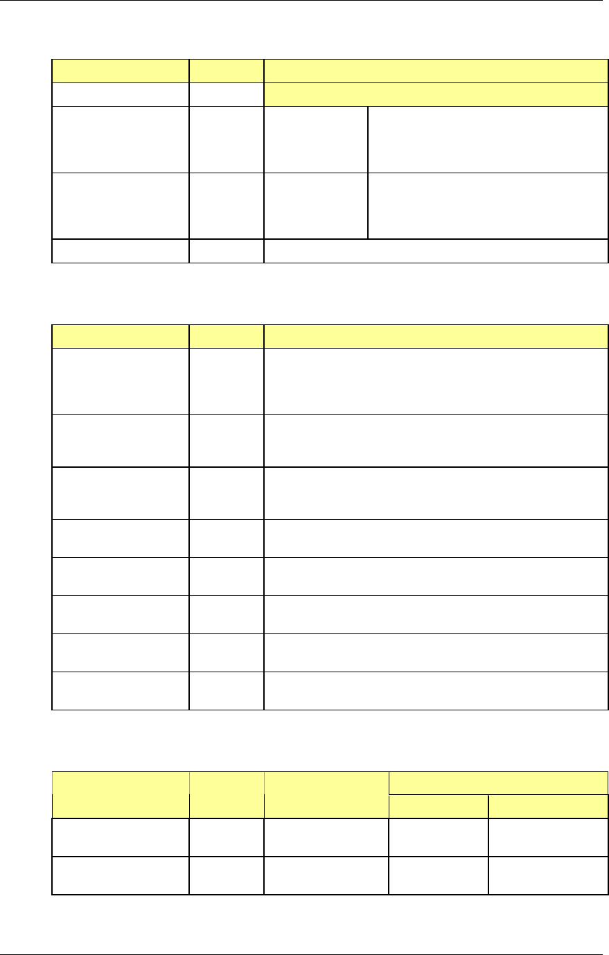
Method of Procedure
Pre-Installation
36 RFN_3.1 Beta
System Unit Power
Output
Power Plant Rectifier Current 20 Amperes/Rectifier for 100/120
VAC
30 Amperes/Rectifier for 200/240
VAC
Output
Paralleling &
Hot Insertion
Each rectifier has an output o-ring diode
in the –48 VDC lead for the purpose of
paralleling and hot insertion in a working
system.
Battery 105ah; VRLA
3.3.5 Grounding
System Unit Grounding
Main Rack #2 AWG green-insulated copper wire between the main
rack and the master ground bar
do not daisy-chain multiple equipment cabinet grounds
using a single ground wire
RadioFrame System NCU internal grounding (UL and CE safety certified)
bonding point provided for protective earth grounding;
#8 screw with internal sems washer
ACU
internal grounding (UL and CE safety certified)
bonding point provided for protective earth grounding;
#8 screw with internal sems washer
iDEN Interface iSC-3 (1) #6 AWG ground wires are attached from the ground studs
on the rear of the iSC-3 to the cabinet ground bus bar
iSC-3 (2) #6 AWG ground wires are attached from the ground studs
on the rear of the iSC-3 to the cabinet ground bus bar
EAS #6 AWG ground wires are attached from the ground studs
on the rear of the EAS to the cabinet ground bus bar
CSU #6 AWG ground wires are attached from the ground studs
on the rear of the CSU to the cabinet ground bus bar
Power Plant Rectifier #6 AWG ground wires are attached from the ground studs
on the rear of the Rectifier to the cabinet ground bus bar
3.3.6 Environment
Operating Ambient Temperature System Unit Storage Temp
MIN MAX
RadioFrame System NCU* -40ºF to +158ºF
(-40ºC to +70ºC)
+32ºF (0ºC) +104ºF (+40ºC)
ACU* -40ºF to +158ºF
(-40ºC to +70ºC)
+32ºF (0ºC) +104ºF (+40ºC)
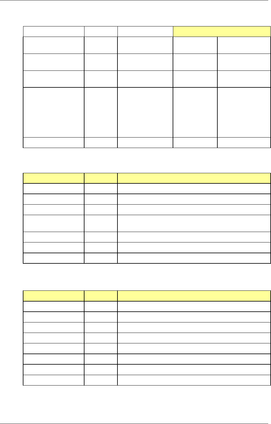
RadioFrame System
Pre-Installation
RFN_3.1 Beta 37
Operating Ambient Temperature
iDEN Interface iSC-3 -40ºF to +185ºF
(-40ºC to +85ºC)
-22ºF (-30ºC) +140ºF (+60ºC)
EAS -40ºF to +185ºF
(-40ºC to +85ºC)
+32ºF (0ºC) +122ºF (+50ºC)
CSU -40ºF to +185ºF
(-40ºC to +85ºC)
+32ºF (0ºC) +122ºF (+50ºC)
Power Plant Rectifier -40ºF to +185ºF
(-40ºC to +85ºC)
+32ºF (0ºC) Sea level to
4800’: 122ºF
(50ºC)
4800-7000’:
113ºF (45ºC)
7000-10,000’
+104ºF (+40ºC)
Battery 77ºF (+25ºC) -40ºF (-40ºC) +122ºF (+50ºC)
* Altitude: -200 to +8,000 feet above mean sea level; above 8000’ reduce maximum operating ambient
temperature by 2ºC per 1000’ to a maximum of 13,000’.
System Unit Relative Humidity
RadioFrame System NCU 10-90% non condensing
ACU 10-90% non condensing
iDEN Interface iSC-3 5-90% non condensing
EAS 5-90% non condensing, non-operating
0-90% non-condensing, operating
CSU 5-90% non condensing
Power Plant Rectifier 5-90% non condensing
Battery N/A
3.3.7 Heat Load
System Unit BTUs per Hour
RadioFrame System NCU 700
ACU 700
iDEN Interface iSC-3 (1) 140
iSC-3 (2) 140
EAS 170
CSU 17
Power Plant Rectifier 13.5 KBTUs (max)
Battery 683
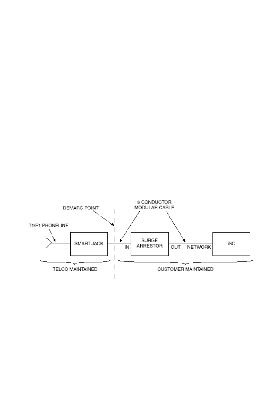
Method of Procedure
Pre-Installation
38 RFN_3.1 Beta
3.3.8 GPS Antennas
The following apply to the GPS antenna array:
• For cable runs up to 166 feet, use ½” diameter LDF.
• For cable runs from 167-290 feet, use 7/8” diameter LDF.
• For cable runs longer than 290 feet consult with the RFN customer’s RF
Engineering.
• For interior cable runs from Polyphaser to site control cabinet use ½”
diameter FSJ.
• Terminate all LDF within 6" of antenna.
3.3.9 Surge Arrestors
The local telephone company installs the T1/E1 line, which terminates in an 8-pin
modular plug. This demarcation (demarc) point connects to the T1/E1 through a
surge arrestor. The following illustration shows the T1/E1 interface with the
iDEN/802.11b RFS.
Figure 15 Telco (T1/E1) interface with the iDEN/802.11b RFS.
The surge arrestor must be adequately grounded as outlined in the Quality
Standards Fixed Network Equipment - Installation Manual (R56). The surge
arrestor usually mounts near the demarcation (demarc) point. The cable
connecting the surge arrestor to the Telco SmartJack should be locally procured,
or should be provided with the surge arrestor. The cable connecting the iSC-3 to
the surge arrestor is locally procured. The following table lists RFN-approved
surge suppression equipment.

RadioFrame System
Pre-Installation
RFN_3.1 Beta 39
AC Data Part # Application Clamp Voltage
TJ1010B T1/E1 Surge Suppression, SAD + Gas Tube Hardwire
and/or RJ connection
10 V
TJ3010B T1/E1 Surge Suppression, SAD + Gas Tube Hardwire 7 V
3.3.10 Cable Support
This section describes requirements for cabling within equipment cabinets and
racks. Cabling within racks and cabinets shall conform to the requirements of
NFPA 70, Article 300, Article 800, Article 810, and Article 820. (Refer to
ANSI/TIA/EIA-568(a) and 569(a) for additional information.)
All cables shall be installed and routed so that personal safety and equipment
functionality is not compromised and that all equipment is accessible for
servicing. The following requirements apply to cabling installed in racks or
cabinets.
3.3.10.1 Securing cabling within racks or cabinets
To help prevent damage or accidental disconnection, cables and conductors
shall be secured at intervals of no more than 3 ft (91 cm). Attachment shall be
accomplished in a manner that does not restrict access to the equipment in the
rack or cabinet.
Insulated standoffs are recommended for use in racks or cabinets. The standoffs
should be of sufficient length to maintain the proper cable separation.
Nonmetallic cable ties shall be used to secure cables and conductors.
Attachment shall be tight enough to secure cables without crushing them.
Cables that span a gap greater than 2 ft (61 cm) shall be supported.
3.3.10.2 Routing cables within racks and cabinets
Grounding conductors within racks or cabinets shall be routed toward the RGB,
MGB, SSGB, or ground bus conductor. Connections to the RGB or ground bus
conductor shall always be made with the equipment grounding or tap conductors
being routed toward the MGB, SSGB, or RGB.
At points where grounding conductors must pass through a hole in a metallic
surface and the hole is slightly larger than the conductor, the conductor shall be
bonded to the metallic surface through which it passes. If the hole or opening is
much larger than the conductor, and it is intended to accommodate several
conductors, the conductor is not required to be bonded.
Cables in racks or cabinets shall be sized to length, and shall be installed and
routed neatly and in a professional manner.
Excess cable shall not be coiled on top of cabinets or racks.

Method of Procedure
Pre-Installation
40 RFN_3.1 Beta
AC power cords longer than necessary may be looped down and back up a rack
or cabinet. Excess lengths of AC power cord shall not be coiled on top of racks or
cabinets.
3.3.10.3 Protecting cables within racks and cabinets
Grounding conductor tap joints shall be installed in order to prevent the
conductor or connection device from coming in contact with metallic surfaces.
Where cables or conductors are routed through holes in metallic surfaces or near
sharp edges, the sharp surfaces shall be suitably protected with a grommet or
similar material to help protect the cable or conductor from damage caused by
sharp edges.
3.3.10.4 Cable bending radius within racks and cabinets
Grounding conductors of all sizes shall maintain a minimum bending radius of 8
in. (20 cm). The angle of any bend shall be not less than 90°.
The bending radius of CAT 5 cables shall be not less than 10 times the outside
diameter of the cable. Follow the cable manufacturer's recommendation and refer
to ANSI/TIA/EIA-568 and CSA-T529 for additional information.
All other cables shall not have sharp bends that will damage or degrade the
performance of the cable. The cable manufacturer's specifications shall be
followed.
3.3.10.5 Cable separation and grouping within racks or cabinets
Cabling in racks or cabinets shall be grouped according to function.
Cable groups within racks and cabinets shall be separated by a minimum of
2 in. (5.1 cm) from other cable groups. Refer to ANSI/TIA/EIA-568a and -569;
and NFPA 70, Articles 800-52, 810-18, and 820-52 for more information.
3.3.11 Alarm Blocks
All alarm wires shall be tagged and labeled with the appropriate alarm item. All
contacts will be normally closed, dry, and isolated from ground. Alarm wire will be
neatly run and secured using nylon cable ties/clamps every three feet to walls
and existing cable tray. All alarm wiring shall be two-wire, 22 AWG.
3.4 Remote ACUs
Up to seven remote ACUs may be installed for a total of 8 ACUs per NCU.

RadioFrame System
Pre-Installation
RFN_3.1 Beta 41
3.4.1 Mounting
Remote ACUs are located in telco rooms or other closets throughout the building,
mounted in 19” EIA-standard compliant racks or equivalent. Any other method
used to mount the remote ACU is not approved, and could void the warranty on
the product and other components in the RFS.
NOTE: The ACU may be placed on a flat surface only if the front and back of the
unit are accessible and if the side vents are not blocked. In this case, the ACU is
not secured and, therefore, is not rated to withstand any level of earthquake, and
the warranty may be voided.
Currently, the remote ACU does not include a Universal Power Supply (future
enhancement). Grounding of the remote ACU is not required by RadioFrame
Networks and is the responsibility of the RFN customer or its customer. A
bonding ground point for protective earth grounding is provided; #6 screw with
internal sems washer.
3.4.2 Clearances
• Dimensions: 19" wide x 7" high x 13" deep (approx.)
3.4.2.1 Back
• 7”
3.4.2.2 Front
• 12”
3.4.2.3 Sides
• Left side (facing unit): 0”; right side: 2”
3.4.2.4 Above
• Above: 0”
3.4.3 Weight
• 27 lbs (fully loaded)
3.4.4 Power
• 100-240 Volts AC, 47-63 Hz, 8-3.5A , or
• Negative 48-56 Volts DC, 11A

Method of Procedure
Pre-Installation
42 RFN_3.1 Beta
3.4.5 Grounding
The ACU is internally grounded by connecting the appliance inlet earthing ground
to the power supply ground terminal.
The chassis unit is also internally bonded by connecting the appliance inlet
earthing ground directly to the chassis (#6 AWG screw with internal sems
washer).
3.4.6 Environment
• Operating Ambient Temperature: 0oC to +40oC (+32oF to +104oF)
• Altitude: -200 to +8000 feet above mean sea level; above 8000', reduce
maximum operating ambient temperature by 2oC per 1000' to a maximum of
13000'
• Storage Temperature: -40oC to +70oC (-40oF to +158oF)
• Relative Humidity: 10-90% non condensing
• Shock: 40 g’s
• Vibration: Level 3 earthquake
• Keep product free from dust, wind, salt, liquids
3.4.7 Heat Load
• 700 BTUs
3.4.8 Cable Support
• Power cord
• CAT 5 wiring to NCU
• CAT 5 wiring to as many as 8 RFUs
3.5 RFUs
3.5.1 Location
RFU placement is determined by first choosing an approximate location for each
RFU using basic coverage requirements, then identifying the mounting
configuration for each RFU (ceiling or wall). The number of RFUs is determined
by dividing an area’s square footage by the minimum RFU coverage area,
(32,000’). Typically, a floor plan of each story in the building is used as an aid to
identify RFU placement.

RadioFrame System
Pre-Installation
RFN_3.1 Beta 43
In addition, RFU placement requires taking into consideration such factors as
interior structures, multiple-floor installations, elevators and stairwells, and
neighboring macro cell systems. For more information, refer to the RFN
document, RF Planning Guide for RadioFrame Systems (990-1001-00).
3.5.2 Mounting
Once the approximate RFU locations have been identified, determine the
mounting configuration required for each RFU—on or above the ceiling, or on a
wall. Wall mounts are ideal, provided the wall is of low density. Mounting the RFU
to a structural brick or concrete wall can alter the unit’s omni directional pattern.
Also, each RadioBlade installed in an RFU is supplied with an antenna designed
to be installed vertically and pointed down. Do not change this orientation.
Suspended ceilings are very common in commercial buildings and mounting the
RFU above the ceiling can work well, provided lower half of the RFU is kept clear
of metal objects such as water pipes, wire bundles and light fixtures. The added
benefit of an above-ceiling installation is that the RFU is hidden yet still easily
accessed. Generally, suspended ceiling panels are of low-density lightweight
materials that do not attenuate RF. The metal grid supports typically are spaced
at greater than 2-foot intervals and will not dramatically affect the RFUs’
performance if they are kept at least 1-foot away from the antennas.
3.5.3 Clearances
• Dimensions: 13.5" wide x 8" high x 5" deep (approx.)
3.5.3.1 Back
• 0”
3.5.3.2 Front
• 0”
3.5.3.3 Sides
• 0”
3.5.3.4 Above
• Leave at least 1.25” between the top of the RFU and the ceiling or any
overhead structure.
• Leave at least 3” below the RFU.

Method of Procedure
Pre-Installation
44 RFN_3.1 Beta
3.5.4 Weight
• 12 lbs (fully loaded with 7 RadioBlades/RAPs)
3.5.5 Power
• Negative 36-56 Volts DC, 0.8A
3.5.6 Grounding
• No additional grounding required
3.5.7 Environment
• Operating Ambient Temperature: 0oC to +40oC (+32oF to +104oF)
• Altitude: -200 to +8000 feet above mean sea level; above 8000', reduce
maximum operating ambient temperature by 2oC per 1000' to a maximum of
13000'
• Storage Temperature: -40oC to +70oC (-40oF to +158oF)
• Relative Humidity: 10-90% non condensing
• Shock: 40 g’s
• Vibration: Level 3 earthquake
• Keep product free from dust, wind, salt, liquids
3.5.8 Heat Load
• 85 BTUs
3.5.9 RF Exposure
To comply with FCC RF exposure requirements, iDEN antennas must be
installed to provide at least 9 inches (20 cm) separation from all persons, with
antenna gain not exceeding zero (0) dBi.
3.5.10 Cable Support
• CAT 5 wiring to ACU

RadioFrame System
Pre-Installation
RFN_3.1 Beta 45
3.6 RadioBlades
3.6.1 Mounting
• The iDEN RadioBlades are inserted into the RFU.
• RFUs must be mounted in such a way that the iDEN RadioBlade antenna
points downward to the ground.
• To prevent RF attenuation within the RFU, a ground strap is placed between
the iDEN RadioBlades and the RadioBlade antennas.
3.6.2 Clearances
• Dimensions: 3” wide x 4” high (plus antenna) x 0.5” thick (approx.)
• The iDEN RadioBlade is housed in the RFU. If the RadioBlade is properly
inserted into the RFU, no additional clearances are required.
3.6.2.1 Back
• 0”
3.6.2.2 Front
• 0”
3.6.2.3 Sides
• 0”
3.6.2.4 Above
• 0”
3.6.3 Weight
• 0.5 lb (approx.)
3.6.4 Power
• 3.3 VDC, 720mA max
• 2.5 VDC, 50mA max

Method of Procedure
Pre-Installation
46 RFN_3.1 Beta
3.6.5 Grounding
• No additional grounding is required
3.6.6 Environment
• Operating Ambient Temperature: 0oC to +40oC (+32oF to +104oF)
• Altitude: -200 to +8000 feet above mean sea level; above 8000', reduce
maximum operating ambient temperature by 2oC per 1000' to a maximum of
13000'
• Storage Temperature: -40oC to +70oC (-40oF to +158oF)
• Relative Humidity: 10-90% non condensing
• Shock: 40 g’s
• Vibration: Level 3 earthquake
• Keep product free from dust, wind, salt, liquids
3.6.7 Heat Load
• Not applicable
3.7 RAPs
3.7.1 Mounting
• The 802.11b RadioFrame Access Points (RAPs) are inserted into the RFU.
• RFUs must be mounted in such a way that the RAP antenna points
downward to the ground.
3.7.2 Clearances
• Dimensions: 3” wide x 4” high (plus antenna) x 0.5” thick (approx.)
• The RAP is housed in the RFU. If the RAP is properly inserted into the RFU,
no additional clearances are required.
3.7.2.1 Back
• 0”

RadioFrame System
Pre-Installation
RFN_3.1 Beta 47
3.7.2.2 Front
• 0”
3.7.2.3 Sides
• 0”
3.7.2.4 Above
• 0”
3.7.3 Weight
• 1 lb (approx.)
3.7.4 Power
• 3.3 VDC, 1.5A
• 2.5 VDC, 1.5A
3.7.5 Grounding
• No additional grounding is required
3.7.6 Environment
• Operating Ambient Temperature: 0oC to +40oC (+32oF to +104oF)
• Altitude: -200 to +8000 feet above mean sea level; above 8000', reduce
maximum operating ambient temperature by 2oC per 1000' to a maximum of
13000'
• Storage Temperature: -40oC to +70oC (-40oF to +158oF)
• Relative Humidity: 10-90% non condensing
• Shock: 40 g’s
• Vibration: Level 3 earthquake
• Keep product free from dust, wind, salt, liquids
3.7.7 Heat Load
• Not applicable

Method of Procedure
Pre-Installation
48 RFN_3.1 Beta
3.8 URU
3.8.1 Mounting
The URU can be placed on any flat surface or mounted using the provided
mounting screws. The URU must be located within 12 feet of an approved power
source.
3.8.2 Clearances
• Dimensions: 5.5" wide x 1.25" high x 5.5" deep (approx.)
3.8.2.1 Back
• 2”
3.8.2.2 Front
• 3”
3.8.2.3 Sides
• 1”
3.8.2.4 Above
• Above: 0”
• Below: 0.125”
3.8.3 Weight
• 1.5 lbs
3.8.4 Power
• 100-240 Volts AC converts to negative 48VDC (power cord provided)*
* The URU uses –48 VDC. The input voltage connector on the URU requires
–48 VDC. The provided power cord includes an external isolated power
supply that converts 100-240 VAC to –48 VDC. The input supply requires 48
volts DC, 2A.

RadioFrame System
Pre-Installation
RFN_3.1 Beta 49
3.8.5 Grounding
• No additional grounding is required
• A ground point for chassis ground is provided: #4 screw with internal sems
washer
3.8.6 Environment
• Operating Ambient Temperature: 0oC to +40oC (+32oF to +104oF)
• Altitude: -200 to +8000 feet above mean sea level; above 8000', reduce
maximum operating ambient temperature by 2oC per 1000' to a maximum of
13000'
• Storage Temperature: -40oC to +70oC (-40oF to +158oF)
• Relative Humidity: 10-90% non condensing
• Shock: 40 g’s
• Vibration: Level 3 earthquake
• Keep product free from dust, wind, salt, liquids
3.8.7 Heat Load
• Not applicable
3.9 Interconnecting Cabling
Site planning requires true single point grounding. The Telco entrance and Telco
termination board should be located as close to the transmission line entry and
AC service entrance as possible. This enables the individual ground leads to
bond to a single point, with the least amount of distance between the ground
leads.
3.9.1 T1
T1 lines are used to connect the RadioFrame System with the Mobile Switching
Center (MSC). Each RFN customer iDEN/802.11b RFS site is typically fed with a
single T1 line, and subsequently protected with a surge suppressor. The
suppressor is located between the "smart jack" (maintained by the local
telephone company) and the Channel Service Unit (CSU). The suppressor
should be grounded downward directly to the master ground bus (MGB) using a
#6 AWG green wire.
The Telco board and the MGB should be mounted adjacent to each other on the
same wall (the coax ground and power ground should also be at this same

Method of Procedure
Pre-Installation
50 RFN_3.1 Beta
location to achieve single point grounding). The Smart Jack and T1 suppressor
are located on the Telco board near the T1 line entrance to the site. The CSU is
located in main rack. The CSU is grounded to the main rack and subsequently to
the master ground bar approximately 15 wire-feet away.
3.9.2 Power Cabling
All electrical wiring for the site must meet the requirements of NEC and all
applicable local codes.
3.9.2.1 AC Power Cabling
This section describes only the AC power. All grounding shall limit the exterior
connections to a single point. The transmission wire entrance for the GPS and
the telco service and board must be installed on a common wall to have true
single point grounding.
Caution
Facility AC wiring within junction boxes, receptacles, and switches shall be performed by a
licensed and bonded electrical contractor. Personnel safety and liability hazards can result
from AC wiring performed by installation personnel other than an electrical contractor.
When an open equipment rack is used, hardwiring of power is not always
possible. Mounting a dedicated simplex receptacle or receptacle assembly on the
rack may be the most convenient method of supplying power, especially if
multiple pieces of equipment are mounted on the rack. This is also a convenient
way to install personal protection type 3 SPD devices (such as Motorola PN
RLN4924A) to the equipment.
These receptacle assemblies can be pre-manufactured and mounted to the top
face of an equipment rack. Mounting can also use a fabricated power pole
mounted between racks.
Equipment that contains its own AC power supply is typically fitted with a
standard grounded line cord. Where this equipment is used, the rack shall be
equipped with a dedicated simplex receptacle or receptacle assembly.
Use only the power cables provided by RadioFrame Networks. Use of any other
cable is strictly prohibited and may void the warranty and/or cause electrical fire
and damage.
Caution
Under no circumstances shall consumer-grade power outlet strips be used In any
Installation. Extension cords of any type shall not be use for connecting line power to
communications equipment.
RadioFrame System
Pre-Installation
RFN_3.1 Beta 51
AC input power
Main Rack: The AC input power for the RFN iDEN/802.11b RFS solution shall
be of 208/240 single phase and shall be coming off one designated 30 amp
breaker. AC input power will be supplied to the Peco II rectifier panel.
Remote ACUs: for 120VAC power, use the power cord provided (use of a
different cord may void the warranty and/or cause electrical fire and damage).
URUs: for 120VAC power, use the power cord provided (use of a different cord
may void the warranty and/or cause electrical fire and damage).
Circuit breakers
Square D QO Plug-On type (30 Amp breaker)
Rectifier frame feeds (for Peco II Rectifiers)
Refer to the PEC 127NHL document for more information.
3.9.2.2 DC Power Cabling
Use of UL approved cable is required; the suggested standard is UL1007.
For RFN equipment, follow the cabling instructions described below for proper
cable gauge, length, and color.
Caution
The power supply cord is used as the main disconnect device; ensure that the socket-outlet is
located/installed near the equipment and is easily accessible.
For -48VDC power, use only an AMP connector Part Number 350766-1 or
equivalent using the following pinout:
Pin Number Wire Connection
1 -48 Volts DC Return (black)
2 -48 Volts DC (red)
3 No connect

Method of Procedure
Pre-Installation
52 RFN_3.1 Beta
Wire shall be sized to carry a minimum of 11 Amps per these recommendations:
Length of Run Minimum recommended wire gauge
Up to 6’ 16 AWG
6’ - 10’ 14 AWG
10’ - 15’ 12 AWG
15’ - 24’ 10 AWG
3.9.3 Category 5 Cabling
All components of the RFS are connected using standard CAT 5 cabling installed
in existing raceways or conduits when available. Use only RJ45 (T568B)
connectors for system components. The same is true for connecting the RFS to
the iDEN Interface and the Customer LAN.
If using a patch panel between RFS components, ensure the following:
• Use only a CAT 5e- or CAT 6-rated patch panel.
• Follow all TIA 568B standards.
• Total impedance, end to end, cannot exceed 8 ohms.
• Use only CAT 5e or CAT 6 wiring.
Maximum length between RFS components shall not exceed 328’ (100 meters).
A Universal Repeater Unit (URU) can be installed to extend the distance
between any two RFS components to 656’ (200 meters).
Up to 2 URUs can be used between any two RFS components to extend the
distance to 984’ (300 meters).
The maximum DC resistance allowed cannot exceed 26.2 Ohms per 1000 feet.
Use plenum rated cable if the cable traverses through a plenum (open air) space.
The proper installation of computer network cabling is critical to the safe and
reliable operation of the computer network. It is recommended that standards
developed by the Telecommunications Industry Association/Electronic Industries
Association (TIA/EIA) and the Canadian equivalent (or equivalent standards in
other countries) be followed. Applicable NFPA codes, local electrical codes, local
building codes and other standards in this manual shall also be conformed to
when installing computer network cabling.
NOTE: It is recommended that a specialist in the installation of computer
networks perform computer network cable installations. The specialist should
have the expertise, knowledge of applicable local codes, and the test equipment
required for a quality installation.

RadioFrame System
Pre-Installation
RFN_3.1 Beta 53
NOTE: This section cites standards from the American National Standards
Institute (ANSI), the Electronic Industry Association (EIA), the
Telecommunications Industry Association/Electronic Industries Association
(TIA/EIA), and the Canadian Standards Association (CSA). Even in non-domestic
installations, these standards should be adhered to.
3.9.3.1 Case Type
CAT 5 Unshielded Twisted Pair (UTP), 100-ohm cable is the recommended
cable type for computer network cabling, and will be the assumed cable type
throughout this section. CAT 5 cable is preferred over CAT 3 and CAT 4 cables
because of its ability to support 100Mbps (Megabits per second) systems and
because of its better immunity to Electromagnetic Interference (EMT) and Radio
Frequency Interference (RFI). Refer to ANSI/TIA/EIA-568-A, and CSA-T529 for
more information.
3.9.3.2 Connecting Hardware
UTP cables shall be terminated with connecting hardware of the same category
rating or higher. This includes all connectors, punch blocks, cross-connect
jumpers and patch cords. It is recommended that hardware used to terminate
cables be of the insulation displacement (IDC) type. Modular connectors shall
also be of the proper typed for the cable used; solid conductor cable uses a
different connector than stranded cable. Refer to ANSI/TIA/EIA-568-A, and CSA-
T529 for more information.
3.9.3.3 Cable and Connector Wiring
Appropriate color-coding and jack pair assignments should be followed when
wiring modular jacks, connectors, and cables. The same wiring standard shall be
used throughout the cabling system. ANSI/TIA/EIA T568B is the recommended
standard. The following illustration shows end views of an 8-pin Modular female
jack for T568B with the pairs and colors identified. Refer to ANSI/TIA/EIA-568-A,
and CSA-T529 for more information.
Warning!
Crimp all connector wiring completely. Ensure that all crimps have fully
penetrated the protective coating on the wiring. Ensure that enough of the
protective coating is left in place to fit inside the connector. Failure to follow
these instructions may cause system failures to occur.
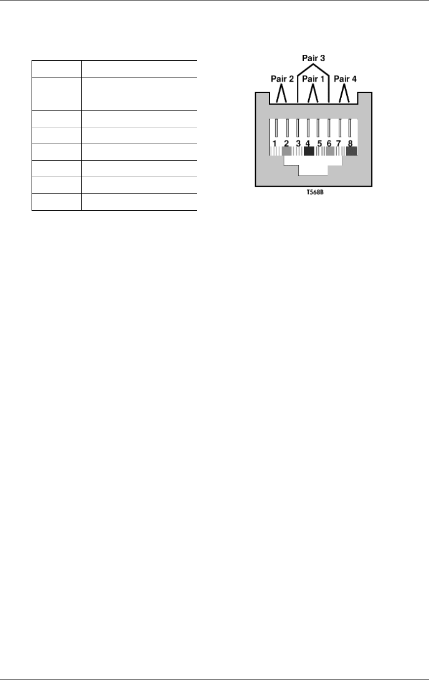
Method of Procedure
Pre-Installation
54 RFN_3.1 Beta
Pin# Color Code (wires)
1 white/orange
2 orange/white
3 white/green
4 blue/white
5 white/blue
6 green/white
7 white/brown
8 brown/white
Figure 16 T568B standard.
3.9.4 Installation
Avoid any unnecessary junction points and cross-connects. Every added junction
point and cross-connect can decrease the performance of the network.
Multiple appearances of the same cable at different locations, referred to as
bridge taps shall be avoided. Each cable segment shall have only one source
and one destination.
Never untwist the twisted pairs of a CAT 5 cable beyond 1.3 cm (0.5 in.) from the
point of termination. Untwisting the wires can decrease the cable's category
performance rating and degrade system performance. Refer to ANSI/TIA/EIA-
568-A and CSA-T529 for more information.
Do not make sharp bends in CAT 5 cable. The bend radius for CAT 5 cable shall
not be less than ten times the outside diameter of the cable. Bending the cable
with a shorter bend radius can affect the electrical characteristics of the cable
and degrade system performance. Refer to ANSI/TIA/EIA-568-A and CSA-T529
for more information.
Do not pull a CAT 5 cable with excessive force. CAT 5 cable should not be pulled
with a force greater than 110 Newtons (25 lbs force), or as suggested by the
cable manufacturer. Pulling a cable with too much force can change the cable's
electric characteristics and degrade its performance. Refer to ANSI/TIA/EIA-568-
A and CSA-T529 for more information.
Do not over tighten CAT 5 cable with cable ties or other supports. Over tightening
cable ties or other supports can change the electrical characteristics of the cable
and degrade the system performance. Refer to ANSI/TIA/EIA-568-A and CSA-
T529 for more information.
CAT 5 segment lengths shall not exceed 100 m (328 ft.). This includes 90 m
(295 ft.) of building cabling and up to 10 m (32.8 ft.) of equipment cords, cross-

RadioFrame System
Pre-Installation
RFN_3.1 Beta 55
connects and patch cords. Of the 10 m (32.8 ft.) allowed for equipment cords,
cross-connects and patch cords, a maximum of 3 m (9.8 ft.) should be used from
the computer workstation to the information outlet. Refer to ANSI/TIA/EIA-568-A
and CSA-T529 for more information.
For simplifying installation and reducing cable runs, a single CAT 5 cable may be
run from the equipment room hub to an additional hub in the computer
workstation area for distribution to the individual computers. This can reduce the
number of cables required between the equipment room and the individual
computers. Refer to ANSI/TIA/EIA-569-A for more information.
If cable segments need to be extended beyond 100 m (328 ft.), an additional hub
may be installed. Each individual segment between hubs shall not exceed 100 m
(328 ft.). Note that no more than the one intermediate hub shall be used. If the
required distance is greater than, a specific cabling system shall be engineered.
Refer to ANSI/TIA/EIA-569-A for more information.
3.9.4.1 NEC Compliance
All RadioFrame Networks products and equipment are NEC compliant.
3.9.4.2 Local Jurisdictions
Local jurisdiction codes shall apply and override any other requirements specified
in this document.
3.9.4.3 Routes
Consideration should be given to using some method of cable management and
containment for runs of CAT 5 cable. Such methods can be dedicated cable
runs, lay-in wireways, cable runways and conduits. Refer to ANSI/TIA/EIA-569-A
and CSA-T530 for more information.
CAT 5 cable shall not be installed in the same conduit, cable runway, outlet box,
or similar device with AC power cables, unless separated by a barrier as allowed
in NFPA 70, Article 800-52. Doing so can be unsafe and is likely to cause EMI
onto the CAT 5 cable, causing network errors. Refer to NFPA 70, Article 800-52,
ANSI/TIA/EIA-568-A, and CSA-T529 for more information.
Precautions should be taken to avoid routing CAT 5 cable near sources of
EM/RFI. Such noise sources may be electrical power wiring, dimmer switches,
radio frequency transmitters, motors, generators, and fluorescent lights.
Precautions may include, increasing the physical distance between the CAT 5
cable and the source of the EMI/RFI, installing the CAT 5 cable inside of a
grounded metallic conduit, or use of a CAT 5100-ohm screened twisted pair
cable as permitted by ANSI/TIA/EIA-568-A. Routing cables near sources of
EMI/RFI can cause data errors and degraded system performance. Refer to
ANSI/TIA/EIA-568-A and CSA-T529 T530 for more information.

Method of Procedure
Pre-Installation
56 RFN_3.1 Beta
Cables shall be separated by at least 5.1 cm (2 in.) from AC power conductors.
Refer to NFPA 70, Article 800-52 for more information.
CAT 5 cables installed in ducts, plenums, and other air-handling spaces shall be
installed in accordance with other sections of this document and NFPA 70, Article
300-22. Also refer to NFPA 70, Article 645.
CAT 5 cables installed in hazardous areas as defined in NFPA 70, Article 500
shall be installed in accordance with NFPA 70, Article 500 and any other
applicable electrical and building codes.
CAT 5 cable shall not be attached by any means to the exterior of a conduit or
other raceway as a means of support. Refer to NFPA 70, Article 725-54 and
NFPA 70, Article 800-52 for more information.
Suspended ceiling support rods and wires may be used as a means of support
for computer network cabling if used in conjunction with appropriate cable
fasteners. Refer to ANSI/TIA/EIA-569-A and CSA-T530 for more information.
CAT 5 cables shall not be laid directly on the tiles of a false ceiling. Refer to
ANSI/TIA/EIA-569-A and CSA-T530 for more information.
CAT 5 cables shall not be run from one building to another building. If the
computer network needs to be extended to another building, a specific cabling
system shall be engineered. Options for extending from one building to another
may include the use of fiber optic cable or a T1. Computer network cabling
entering and/or leaving a building shall be properly grounded and protected from
surges as required elsewhere in this document.
3.9.4.4 Testing
Every effort should be made to ensure a quality installation of the computer
network cabling system. Even the best installation effort cannot guarantee a
properly working system. It is therefore required that a computer network cabling
system be tested for proper performance.
The procedures and specifications in the TIA/EIA Telecommunications System
Bulletin (TSB) 67 shall be used for this testing. TSB 67 has four primary
parameters to test. Below is an overview of the four test parameters needed to
assure a properly working system.
Wire map
The wire map test is used to verify wire pair to pin termination at each end of the
cable and to check for installation connectivity errors. It is recommended that
100% of cables be tested using a testing tool such as Microtest® Microscanner™
Pro. (Be sure the tester can check for a “split pair” configuration).
Each of the 8 conductors in the cable are tested for:
• Conductor continuity to the remote end of the cable

RadioFrame System
Pre-Installation
RFN_3.1 Beta 57
• Shorts between any two or more conductors in the cable
• Crossed pairs in the cable
• Reversed pairs in the cable
• Split pairs in the cable
• Any other wiring errors in the cable
Length
The length test is used to determine the maximum physical length of the cable
segments. The Microscanner™ Pro and many other models can be used to
check cable, which are accurate within a few feet. The RFN guideline for cable
length is 100 meters (approximately 328’ for less).
Attenuation
Attenuation is the measure of signal loss in the cable segment.
Near-End Crosstalk (NEXT) loss
NEXT loss is a measure of signal coupling from one wire pair to another within a
single UTP cable segment.
3.9.4.5 Labeling
Cabling shall be identified with a standardized, double-ended system to facilitate
cable and equipment connection identification. (Refer to ANSI/TIA/EIA-606 for
more information.) The label should show the following:
• Equipment identification for each end of cable.
• Connector reference designator for each end of cable.
• Direction along the cable where terminating equipment is located.
• Floor and room of the equipment.
In general, the following considerations need to be observed in implementing a
labeling system:
• Labeling shall indicate the destination ends of the cable, in terms of
equipment name and connector reference designator or name. This applies
to connectorized, lugged, or punched-down cable terminations, regardless of
the application (RF, audio, or control).
• Labeling shall be imprinted on white opaque material (preferably plastic or
plasticized paper) using indelible black ink.

Method of Procedure
Pre-Installation
58 RFN_3.1 Beta
• Labeling should wrap entirely around the cable. It should be secure enough
to assure label retention if the cable is to be pulled through conduit.
• Label placement shall be between 10 and 16 cm (4 and 6 in.) from each end
of the cable (or the most logical point that would allow the label to be easily
read).
• Information printed on each label should be brief but clearly understandable.
Because of limited space, abbreviations and acronyms should be used. If
abbreviations are used, they should be industry standard.
• All cables shall be properly labeled by the manufacturer as to the type,
capacity, and approval ratings of the cable.
3.10 Main Rack Configuration
The following illustration shows a typical main rack installation for a RadioFrame
System. The main rack contains the iDEN Interface, the NCU and one ACU of
the RadioFrame System, and the Power Plant. The rack must be an EIA-
standard compliant rack, or equivalent.
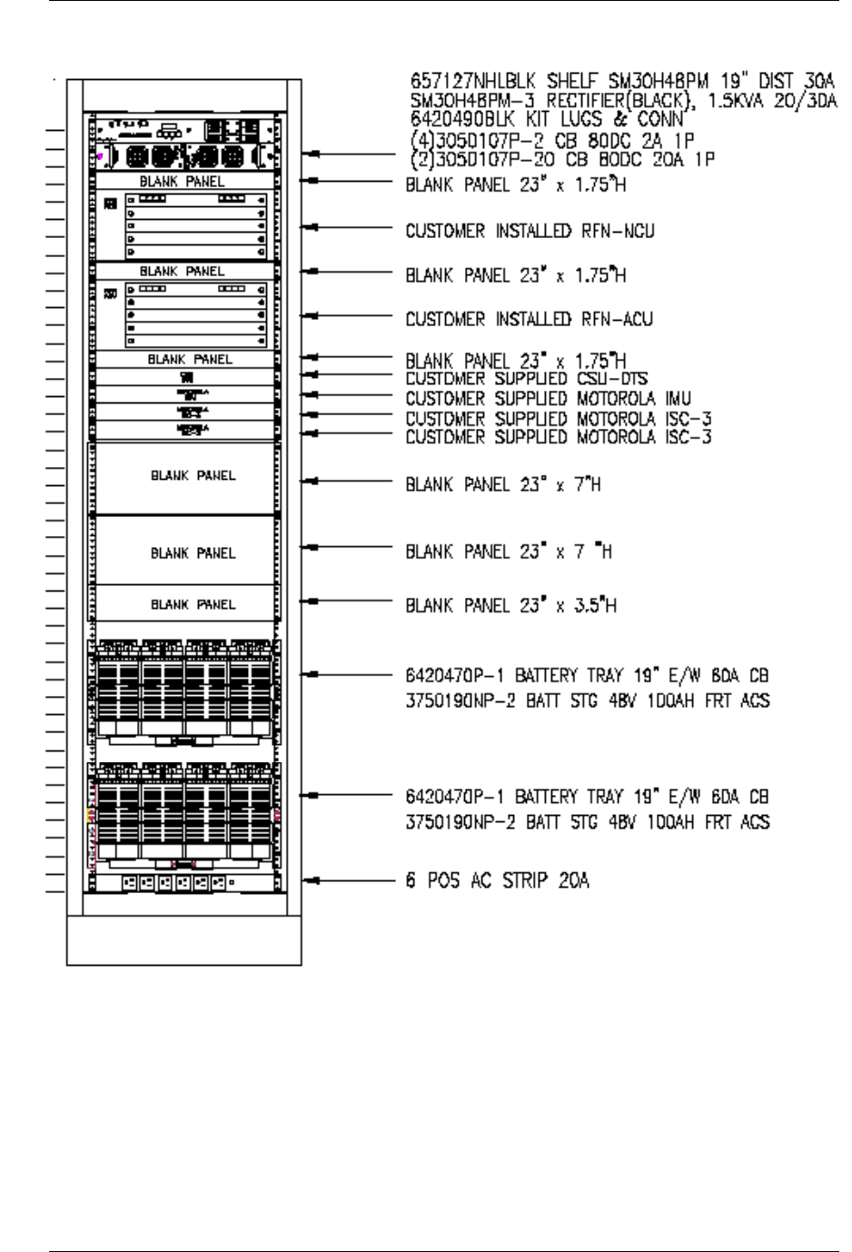
RadioFrame System
Pre-Installation
RFN_3.1 Beta 59
Figure 17 Standard 19" 7’ rack configuration and power requirements for the
RadioFrame System.

Method of Procedure
Pre-Installation
60 RFN_3.1 Beta
3.11 RF Planning
RF planning places a minimum number of RadioFrame Units in locations that will
provide optimal coverage and voice quality. RF planning for the RadioFrame
System takes into consideration anything that might affect RF propagation,
including:
• RFU locations, including coverage and mounting requirements, multi-story
installations, and elevator shafts and stairwells
• Simulcasting, including single-sector and multi-sector systems
• Interference, including out-of-building emissions and in-building interference
from macro systems
• RFN recommends using three channels of separation
For more information about site planning, refer to the RFN document, RF
Planning Guide for RadioFrame iDEN Systems (990-1001-00).
3.12 Site Survey
An informal site survey can be conducted to determine RFS equipment locations.
Based upon the RFS square footage model, preliminary site designs are
relatively easy to calculate prior to a formal site survey (refer to Appendix B “Site
Survey” for an example of site survey questions and information).
3.13 Alarm Configuration
Various alarms or sensors are installed within the RFN customer RFS site
building. All alarm wiring terminates at the Environmental Alarm System (EAS)
location within the main rack. The electrical contacts for the alarms must be dry
contacts and normally remain closed (open on alarm).
3.14 Tools Required
The RadioFrame System comes with all the parts necessary to mount each
component of the system. This section describes all of the equipment necessary
to install the RadioFrame System.
3.14.1 Hand Tools
• #2 Phillips screw driver.
• Optional: For RFU ceiling mounts, a drill with a 3/16” bit for use with provided
wood screws, or a 9/32” bit and four ¼” bolts (not provided).

RadioFrame System
Pre-Installation
RFN_3.1 Beta 61
3.14.2 Laptop Computer
A laptop computer is required to bring up the RFS. The laptop must be loaded
with the following fully functional equipment (or equivalent):
• Serial cable
• Adapter for APC/NPC cards
• Ethernet cables to connect to the RLIC:
- crossover EIA/TIA 658A
- straight through EIA/TIA 568B
• EtherPeek
• CD-ROM capability
• FTP server (WFTPD)
• Telnet and serial communications software (TeraTerm)
• Administration rights to change settings on laptop
3.14.3 System Manager Software
• Loaded on RLIC, which is used for the download
• Up-to-date version loaded on the laptop (backup)
• Loaded on a CD ROM (backup)
• New versions can also be downloaded from RFN web site (backup)
3.14.4 IP Addresses for all cards in the RFS
• RadioFrame LAN Interface Cards (RLIC)
• Network Processing Cards (NPC)
• RadioFrame Interface Cards (RIC)
• Airlink Processing Cards (APC)
3.14.5 iSC-3 Configuration
• Data fill of iSC (refer to RFN Recommended Data Fill, P/N 998-0100-00)
• Method by which regional office identifies sector/cabinet positions
3.14.6 Test Equipment
• Ethernet cable tester

Method of Procedure
Pre-Installation
62 RFN_3.1 Beta
3.14.7 Additional Materials
• Wire ties
• Straight blade screwdriver
• Spare RJ45 connectors
• Wire cutters
• RJ45 connector crimper

RadioFrame System
Installation
RFN_3.1 Beta 63
4 Installation
Following all construction work, both exterior and interior, the site and facility
shall be in a suitable condition for the installation of communications equipment.
In general, the following considerations need to be observed:
• Interior of facility shall be free of excessive dust.
• All refuse related to the installation tasks shall be removed.
Consideration should be exercised when laying out a site to allow primarily for all
code requirements for spacing, and then the most efficient use of space. Special
attention shall be given to future expansion with regard to cable runway heights,
electrical outlet placement, and equipment placement.
The procedures described in this chapter assume the field technician or installer
has knowledge of the installation techniques contained in the Quality Standards
Fixed Network Equipment - Installation Manual (R56).
Prior to performing the installation procedures, prepare the site with all
associated antennas, phone lines, and other related site equipment. This
information is covered in the Pre-Installation chapter. The main rack may already
be installed, depending on the site configuration.
4.1 Main Rack and Supporting Hardware
This section provides installation instructions for a cabinet already containing the
iDEN Interface, RadioFrame Networks NCU and ACU, and the Power Plant. The
procedure listed here is for permanently mounting the equipment cabinet within a
site.
The following procedures describe how to mount non-wheeled cabinets in a
system site building. Be sure to read all of the procedures carefully to ensure a
quality installation.
4.1.1 Main Rack
The main rack must be secured to the floor for optimum stability. Since the main
rack is very heavy, this procedure is written so that the rack is moved only once.
Warning!
Always use two or more persons whenever moving a cabinet. A fully
configured equipment cabinet weighs approximately 800 lbs (360 kg).

Method of Procedure
Installation
64 RFN_3.1 Beta
Perform the following steps to properly install the main rack within the site
building:
1 Measure the mounting location for the main rack within the row.
2 Carefully mark the mounting holes with a pencil, as indicated on the
appropriate main rack footprint.
3 Drill the marked mounting holes to the appropriate depth of the mounting
hardware with a hammer drill and bit.
4 Insert an anchor into the drilled hole.
If necessary, tap the anchor into place using a hammer.
5 Remove the four screws securing the bottom kick panel to the front and back
of the main rack.
Remove the kick panel and set aside during installation.
6 Carefully move the main rack into the position indicated by the holes in the
floor.
Adjust and level the main rack as necessary to align the rack mounting holes
with the pre-drilled holes in the floor.
7 Secure the main rack to the site floor with the locally procured mounting
hardware.
8 If required, connect adjacent cabinets to each other using ganging hardware.
4.1.2 Auxiliary Equipment
Auxiliary equipment for the main rack includes:
• GPS antenna
• Environmental alarm block
• Mandatory alarms
• Optional alarms
• Surge arrestors
• Grounding
• Cable supports
4.1.2.1 GPS Antennas
When locating the GPS antennas, install vertical mast (or antenna mount) at a
location that provides a line of sight to as much of the horizon as possible. Solid
buildings and overhanging trees will block the 1.575 GHz signal and cut down on
the amount of sky visible and therefore the number of satellites the antenna can
see. Satisfactory performance can be achieved with as much as 25 percent of
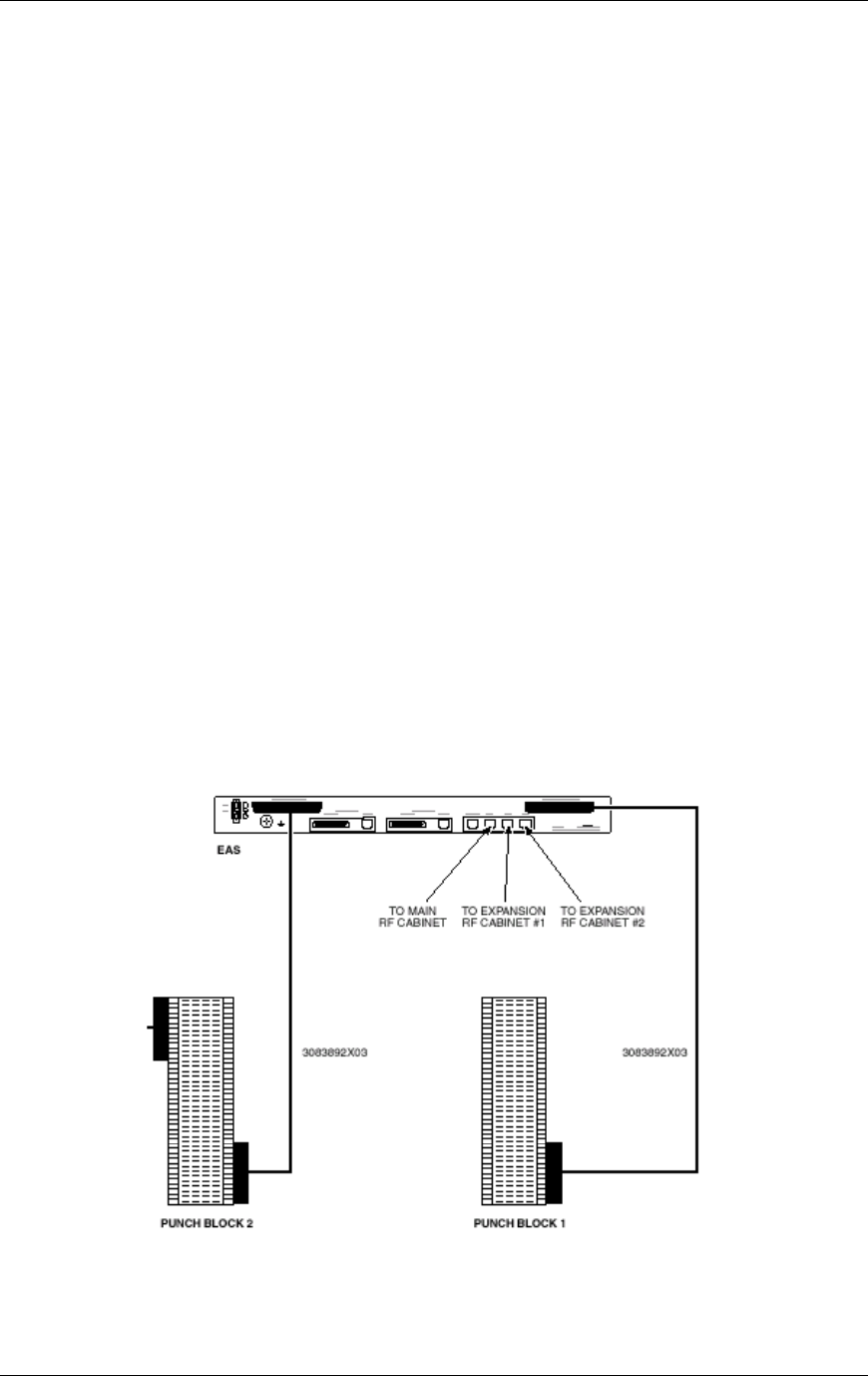
RadioFrame System
Installation
RFN_3.1 Beta 65
the sky being obscured. Reflecting objects such as air conditioners, walls, and
metal surfaces may cause multi-path interference with the GPS signal and
should be kept below 10 degrees above the horizon.
• Minimum separation between GPS antennas is 4 feet.
• GPS antennas should be installed at a height that allows for regional snow
depth.
The antennas may be installed on building tops utilizing mounting hardware
designed to allow physical positioning aiming the antennas to the designated
coverage area sectors. Downtilt brackets should be installed during initial
installation of antenna at all sites other than omni configurations.
Antenna installation shall be per the manufacturer’s instructions. All antennas
shall be placed according to RF engineering information supplied by the RFN
customer. The installation hardware supplied with the antennas by the
manufacturer shall be used unless the RFN customer is supplying special
brackets for unusual mounting.
In order for sites to hand off correctly, each site’s GPS antenna must receive
pulse signals from a minimum of one satellite. From that pulse the sites will set
their “internal clocks” so that all sites will be synchronized.
4.1.2.2 Environmental Alarm Block
Alarm wiring fitted with modular (8-pin Telco) connectors terminate at the EAS.
All other connections are designed to terminate at a punch block.

Method of Procedure
Installation
66 RFN_3.1 Beta
Figure 18 Environmental Alarm Block
Each of the site alarm contacts are normally closed and connected to the EAS
through a 50-pin Champ cable that connects to a punch block. All alarm contact
pairs must be dry (isolated from ground). Most alarm connections are inputs.
Outputs provide a dry relay closure rated at 0.5 Amps, 30 Vrms or 60 Vdc, 10VA
max.
Alarm wiring for the main rack terminates directly to the EAS rear panel. Connect
the alarm cable as shown in the previous illustration.
Four outputs on the User Alarm/Control and System Alarm/Control connectors
are available for customer-defined applications. Diode suppression of inductive
surges is required if anything but a resistive load is connected to this output.
Eighteen customer-defined alarm inputs are available on the User Alarm/Control
connector. The alarms are reported to the Operations and Maintenance Center
(OMC) by the respective alarm code. The OMC must be programmed with the
proper alarm name corresponding to each code. All connections on User
Alarm/Control and System Alarm/Control connectors must be defined and
provided to the OMC to insure the effectiveness of monitoring those alarms.
Backboard
A wall mounted AC grade fire-rated plywood backboard (1/2” x 4’ x 4’) must be
provided within the site. Reserve a two square foot area on the Telco backboard
for dedicated system use.
A 117 VAC dual receptacle outlet (3 prong) should be installed on or adjacent to
the Telco backboard. This outlet can be used for accessories, such as modems
and other AC powered devices. It may also be used as a general service outlet.
4.1.2.3 Mandatory Alarms
RFN recommends site installation of the following alarms:
Alarm Code Alarm Type EAS standard alarm connection
219 Intrusion alarm predefined input, site entry
220 High temperature predefined input, site high ambient temperature
221 Low temperature predefined input, site low ambient temperature
222 Smoke detector (120 VAC) predefined input, site smoke detector
242 Power Plant alarms: AC power failure
243 low DC voltage
244 high DC voltage
245 breaker alarm failure

RadioFrame System
Installation
RFN_3.1 Beta 67
Alarm Code Alarm Type EAS standard alarm connection
246 minor rectifier failure
247 major rectifier failure
4.1.2.4 Surge Arrestors
T1
The T1 surge arrestor must be adequately grounded as outlined in the Quality
Standards Fixed Network Equipment - Installation Manual (R56). The surge
arrestor usually mounts near the demarcation (demarc) point. The cable
connecting the surge arrestor to the Telco SmartJack should be locally procured,
or should be provided with the surge arrestor. The cable connecting the iSC-3 to
the surge arrestor is locally procured.
GPS antennas
All antenna feed lines should terminate with a suitable surge arrestor within 12”
inside of the entry window. Each arrestor must connect to the master ground bar
located below the entry plate. It is recommended that the arrestors be mounted
to a mounting bracket to simplify grounding and cable installation.
AC power (optional)
An RFN customer-approved surge arrestor must be installed adjacent to the AC
power panel. Very short wire lengths between the arrestor and the power panel
are required for proper operation of equipment.
4.1.2.5 Grounding
Within the site, ground the main rack with a single dedicated connection between
the main rack and the master ground bar. The connecting wire must be a #2
AWG green-insulated copper wire.
Use appropriate lugs (and split ring lock washers when possible) with an anti-
oxidant grease applied for interior grounding connections and exterior secondary
grounding connections. If lock washers are used, they should be placed between
the nut and the lug to ensure the mechanical integrity of the connection. The
washer must not be secured between the lug and the surface to which it is
connected. Painted connections must be scraped clean before applying the anti-
oxidant grease and lug.
The main rack (ground bus) must be connected to the site ground using a single
dedicated ground wire.
Method of Procedure
Installation
68 RFN_3.1 Beta
Warning!
Never use a bare or damaged wire for the connection of chassis ground or for the
electrical wiring to prevent damage to equipment or potential injury to personnel.
4.1.2.6 Cable Supports
All installations requiring cable trays shall be the responsibility of the RFN
customer or its customer. Cable tray requirements vary from site to site and are
not specific to the RadioFrame System. All cable tray installations shall receive
permits from and be inspected by the local municipality governing tenant
improvements, including mechanical and electrical inspections. Site plans,
procurement, installation, grounding/bonding, and inspecting of the cable tray
shall be the responsibility of the RFN customer or its customer.
4.2 Remote ACUs
To install a remote ACU, first mount the unit then connect the ACU to the NCU
and each associated RFU. Repeat the following two procedures for each remote
ACU.
4.2.1 Mount the remote ACUs
Mount each remote Airlink Chassis Unit (ACU) as follows:
1 Find these items in the ACU shipping container: one ACU, four mounting
screws, and one 120VAC power cord.
2 Mount the ACU only in an EIA-standard compliant (19”) rack using all 4
screws provided. Refer to the site documentation for the exact location of the
ACU. For safe operation, follow these guidelines:
• Do not mount the ACU in any orientation other than that specified in the
following illustration.
• Mount the ACU so that both the front and the back are accessible.
• If the mounting holes do not line up, adjust the ACU up or down until the
mounting holes line up.
Caution
Do not block the air vents on the sides or rear of the ACU.
3 Plug the ACU into an approved power source with the provided power cord.
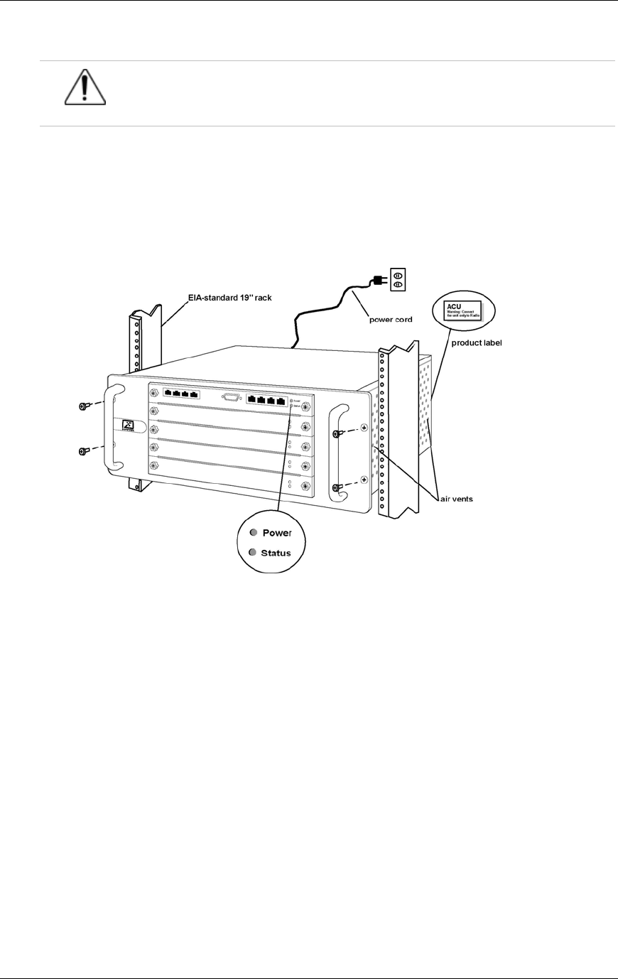
RadioFrame System
Installation
RFN_3.1 Beta 69
Caution
The power supply cord is used as the main disconnect device; ensure that the
socket-outlet is located/installed near the equipment and is easily accessible.
4 Verify that the ACU is receiving power and that all cards installed in the ACU,
front and back, are operational.
Each card installed in the front and back of the ACU has two LEDs: Power
and Status. All LEDs should light green.
Figure 19 Mount the ACU only in an EIA-standard compliant 19” rack.
4.2.2 Connect the ACUs to the NCU and the RFUs
1 Connect Port 1 on the front of the ACU to the specified port (1-8) on the back
of the NCU using an RJ45-to-RJ45 CAT 5 cable (see the following
illustration).
2 Verify that the ACU is connected to the NCU.
The Link and Activity LEDs on Port 1 should both light green, and the Activity
LED should blink rapidly indicating that the connection to the NCU is
operating.
3 Connect the RJ45-to-RJ45 CAT 5 cable for each RFU to the specified port
(1-8) on the back of the ACU.
The Link and Activity LEDs on the ports will remain unlit until each RFU has
been installed.
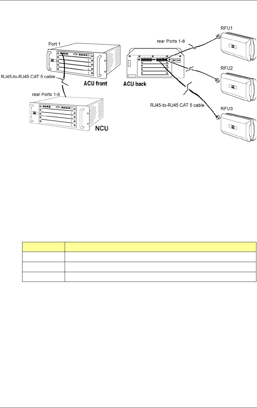
Method of Procedure
Installation
70 RFN_3.1 Beta
Figure 20 Connect Port 1 on the front of the ACU to the specified port (1-8) on the
back of the NCU. Connect RFUs to Ports 1-8 on the back of the ACU.
4.3 URU
The maximum length of CAT 5 wire between RadioFrame System components is
100 meters (approximately 328’). The distance between any two components
can be extended by installing additional CAT 5 cabling and up to two URUs.
# of URUs Maximum CAT 5 Cable Length between RFS components
no URU 100 meters (approximately 328’)
1 URU 200 meters (approximately 656’)
2 URUs 300 meters (approximately 984’)
4.3.1 Installing a URU
Install Universal Repeater Units while wiring the RadioFrame System.
1 Find these items in each Universal Repeater Unit (URU) shipping container:
one URU, mounting screws, and one power cord with a 120VAC-to-negative
48VDC converter.
2 Place or mount the URU on any flat surface (see the following illustration).
The URU can be placed or mounted on any flat surface using the provided
mounting screws. The URU must be located within 12 feet of an approved
power source. Refer to the site documentation for the exact location of each
URU.
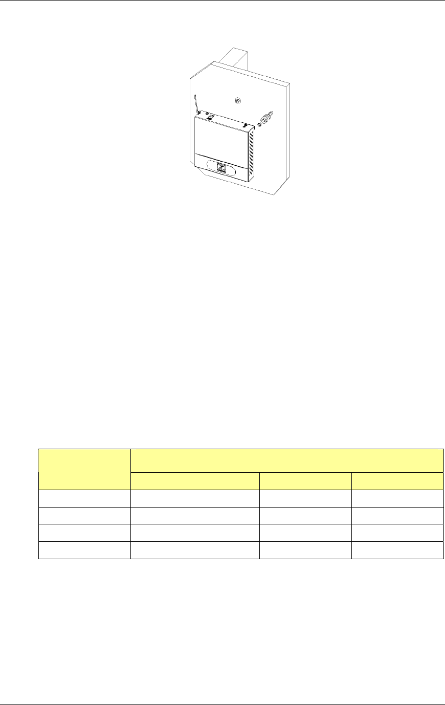
RadioFrame System
Installation
RFN_3.1 Beta 71
Figure 21 The URU can be placed or mounted on any flat surface.
3 Plug the URU into an approved power source, then, using the tie wrap
attached to the URU, secure the power cord to the unit.
4 Verify that the URU is receiving power.
The Power and Status LEDs should both light as green.
4.3.2 Changing the URU Mode of Operation
On the bottom of the URU is a dip switch that is in the “Auto Sense” configuration
by default (see the following illustration). If the URU receives 48 Volts DC on
either “IN” connector, it will output 48 Volts DC on its respective “OUT”
connector. If any other mode of operation is required, set the dip switches as
follows:
Desired Mode of Operation
DIP Switch
Number Auto Sense Power In/Out 48VDC Output On 48VDC Output Off
1 OFF ON OFF
2 OFF ON OFF
3 ON OFF OFF
4 ON OFF OFF
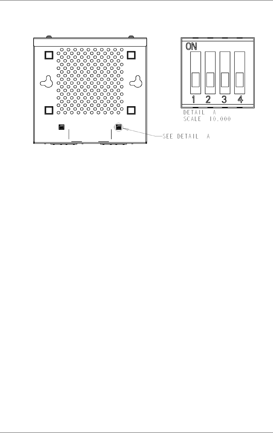
Method of Procedure
Installation
72 RFN_3.1 Beta
Figure 22 The URU dip switch is located on the bottom of the unit and is used to
configure the input and output power for the unit.
4.4 RFU
This section describes the methods used to mount an RFU, including both wall
and ceiling mounts. The RFU is shipped with mounting screws and anchors, two
mounting templates (wall and ceiling), one ceiling bracket (optional), and two
ground straps (one 3-hole and one 4-hole) for the iDEN RadioBlades.
First, mount an RFU, then connect it to the ACU and verify that the RFU is
receiving power from the ACU. Next, insert the RadioBlades into the RFU in the
configuration specified in the site documentation, and replace the front cover on
the RFU.
4.4.1 Mounting and Anchoring
The RFU is to be installed on a wall or on or above the ceiling. The RFU is to be
fix-mounted on indoor permanent structures providing a separation distance of at
least 8 inches (20 cm) from all persons during normal operation and 10 feet
(3 meters) from other RFU mounted assemblies.
The RadioFrame Unit (RFU) is not intended for mounting to drop ceilings.
Mounting this unit to a drop ceiling voids any warranty, expressed, implied, or
otherwise. Mounting this unit to a drop ceiling voids any regulatory agency
approvals, including, but not limited to, Underwriters Laboratories (UL), Canadian
Standards Association (CSA), and the European Community (CE).
NOTE: Mounting the RFU directly to a drop ceiling is expressly forbidden by the
National Electric Code (NEC), National Fire Protection Association (NFPA), and
the Uniform Building Code (UBC). RadioFrame Networks is not liable for any
direct, indirect, special, incidental, or consequential damages arising out of
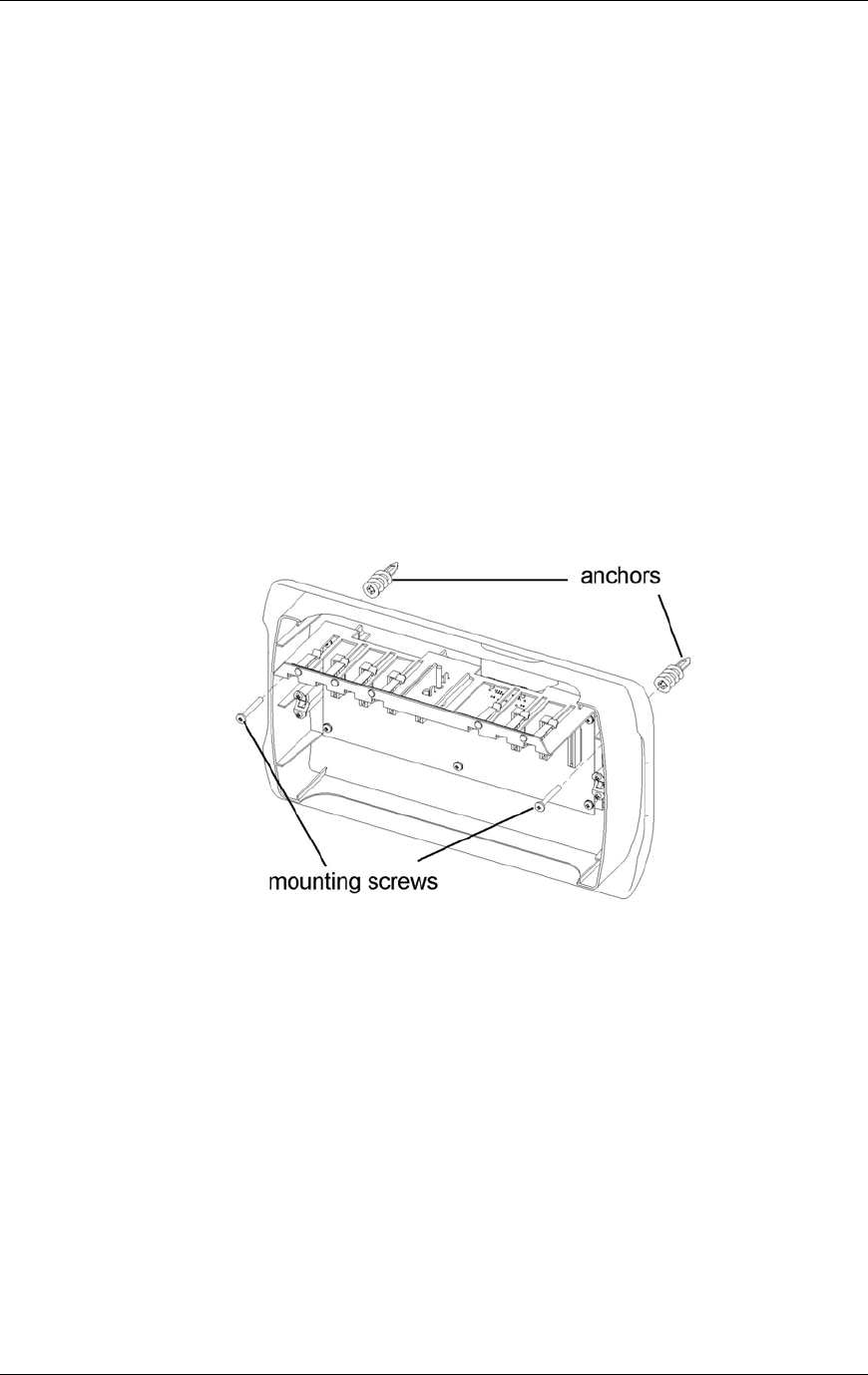
RadioFrame System
Installation
RFN_3.1 Beta 73
mounting this unit in any fashion not recommended and approved by
RadioFrame Networks. This includes, but is not limited to, damage to, or loss of,
equipment, loss of data, or loss of profit, even if RadioFrame Networks was
advised of the possibility of such damages
4.4.1.1 Wall Mount
1 Place the 11” x 17” drawing template (P/N 981-1020-00) on the wall where
the RadioFrame Unit is to be mounted.
2 Mark the two locations indicated on the template.
3 Screw the two supplied anchors into the locations as shown in the following
diagram.
4 Screw the two supplied screws into the anchors, leaving approximately 1/4”
of each screw exposed.
5 Hang the RFU on the anchors and fully tighten both screws.
Figure 23 A wall mount requires two screws to anchor the RFU.
4.4.1.2 Ceiling Mount
1 Place the 8.5” x 11” drawing template (P/N 981-1010-00) on the ceiling where
the RFU is to be mounted.
2 Mark the four locations indicated on the template.
3 Drill four holes with the appropriately sized bit: 3/16” for the provided wood
screws, or 9/32” for 1/4” bolts (bolts not provided).
If using the provided wood screws, ensure that all four screws penetrate
wood. Otherwise, use alternative mounting screws or bolts to secure the
ceiling bracket.
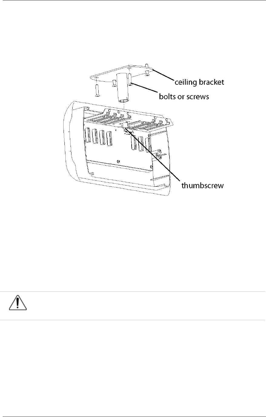
Method of Procedure
Installation
74 RFN_3.1 Beta
4 Using four screws or bolts, attach the ceiling bracket to the ceiling as shown
in the following diagram.
5 Attach the RFU to the ceiling mount bracket and fully tighten the thumbscrew.
Figure 24 Use the provided bracket when mounting an RFU on the ceiling,
ensuring that all bolts or screws penetrate wood.
4.4.2 Connect the RFUs to the ACUs
1 Connect the RJ45 port labeled MAIN on the top of the RFU to the ACU using
an RJ45-to-RJ45 CAT 5 cable (see the following illustration).
Caution
Do not remove the protective cover from or use the RFU port labeled AUX. Damage may
occur to the RFU, ACU, or both.
2 Verify that the RFU is receiving power and connectivity from the ACU.
The Link and Activity LEDs on the MAIN port should light as green, and the
Activity LED should blink rapidly indicating connectivity. If the LEDs do not
light, verify that the ACU is powered on, and if a URU is installed between the
ACU and RFU, that the URU is receiving power.
3 Complete the next procedure “Insert the RadioBlades” before placing the
front cover on the RFU.
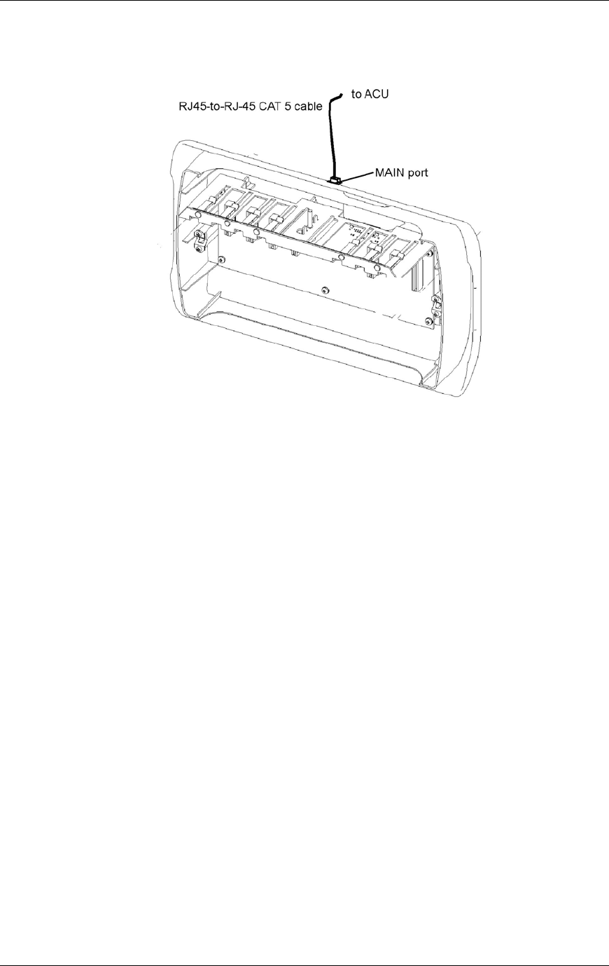
RadioFrame System
Installation
RFN_3.1 Beta 75
Figure 25 Connect the RFU to the ACU, then ensure that the RFU is receiving
power and connectivity from the ACU.
4.4.3 Insert the RadioBlades and RAPs into the RFU
The iDEN RadioBlades and 802.11 RAPs are shipped several to a box in
individually wrapped antistatic packaging. Each box of RadioBlades/RAPs
includes a disposable antistatic wrist strap to be used when inserting the
RadioBlades/RAPs into the RFU. Refer to the site documentation for the exact
slot location of each RadioBlade/RAP within the RFU.
1 Unwrap 30 cm (12”) of the disposable wrist strap and wrap the adhesive side
around your wrist.
2 Unroll the rest of the band and remove the liner from the copper tape.
3 Attach the copper tape to the metal card cage inside the RFU.
4 Un-package the iDEN RadioBlades to be inserted in the RFU.
5 Insert the iDEN RadioBlades, one at a time, into the specified slots (1 through
7) in the RFU until the connector on each RadioBlade seats firmly into the
back of the RFU (see the following illustration).
6 Unscrew the antenna from each iDEN RadioBlade, one at a time, and place
the antennas on an antistatic surface (see the second following illustration).
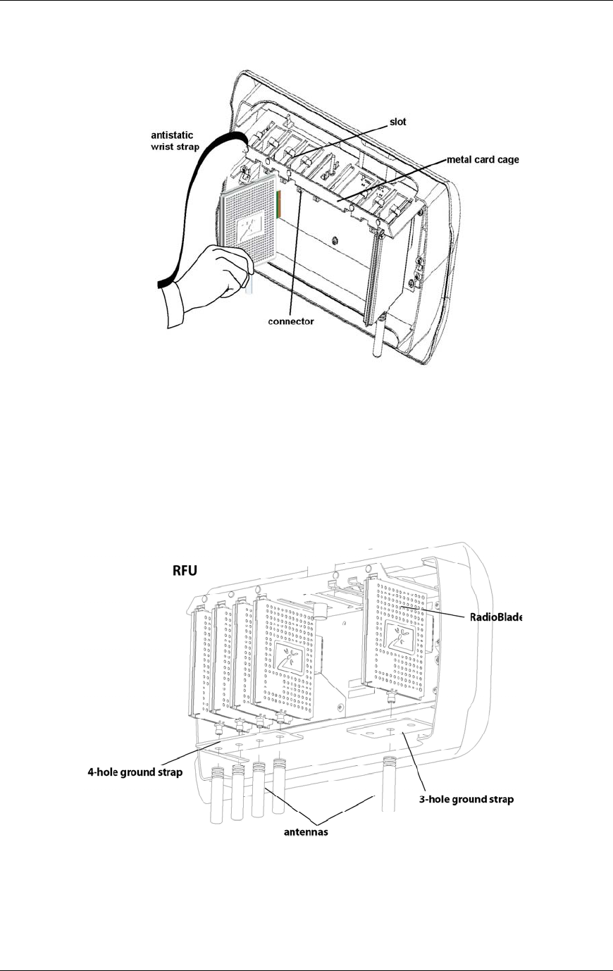
Method of Procedure
Installation
76 RFN_3.1 Beta
Figure 26 Slide each iDEN RadioBlade into the specified slot in the RFU.
7 Place the provided ground strap over the SMA connectors using either the
3-hole ground strap (P/N 510-0931-99) or the 4-hole ground strap
(P/N 510-0933-99) depending on the number and configuration of iDEN
RadioBlades in the RFU (see the following illustration).
Figure 27 Place the ground strap(s) between the iDEN RadioBlades and their
antennas.
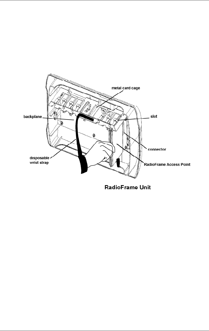
RadioFrame System
Installation
RFN_3.1 Beta 77
8 Holding the ground strap in place, replace each iDEN RadioBlade antenna
one at a time.
9 Insert the 802.11b RAPs, one at a time, into the specified slots in the RFU
until the connector on each RAP seats firmly into the back of the RFU (see
the following illustration).
10 Remove the antistatic wrist strap and place the front cover on the RFU.
Figure 28 Insert the 802.11b RAPs into the specified slots of the RFU.
4.5 Interconnecting Cabling
4.5.1 T1
The Telco interface should have been installed according to the Pre-installation
chapter.
NOTE: The equipment can be installed and tested without the Telco T1/E1
present. The T1/E1 must be connected for proper operation of the site.
NOTE: Some modular cables have a ridge along one side of the cable for
purposes of alignment with the connector.
NOTE: The SmartJack is capable of passing -48V Telco power through to the
site controller. For operation, iDEN does not require this power. If -48V is present
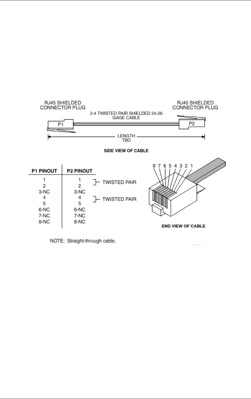
Method of Procedure
Installation
78 RFN_3.1 Beta
on the network connection to the site controller, the SmartJack is incorrectly
configured. Contact the service provider immediately to correct this situation. The
SmartJack switch should be set so that -48V power does not pass through to the
site controller.
If this cable is locally manufactured, crimp the 8-pin connectors as shown in the
following illustration. The wires should be routed straight through. Make sure that
the conductor color is the same at both ends for each conductor of the cable.
Figure 29 T1 interface cable configuration
4.5.2 RFS to iDEN Interface
To connect the RFS to the iDEN Interface, connect the NCU to the iSC-3 using
an Ethernet Media Converter. The Ethernet Media Converter is shipped with
other RadioFrame System equipment in its own container with all the cables
necessary to install it.
Connecting the NCU to the iSC-3
1 Find these items in the shipping box: one MC15 Ethernet Media Converter,
Allied Telesyn User Guide (contains all product specifications), four rubber
feet, one AC-DC power adapter, one 10BaseT Ethernet cable (straight-
through RJ45-to-RJ45 CAT 5 cable), and one 10Base2 cable (50 ohm coaxial
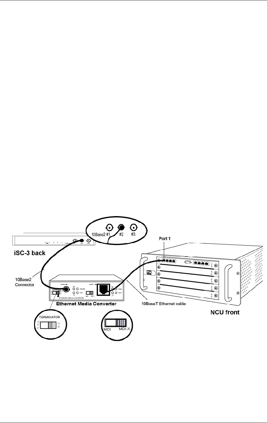
RadioFrame System
Installation
RFN_3.1 Beta 79
cable with two male BNC connectors; one connector is a tee adapter
terminated on end of the tee—this end is connected to the iSC-3).
2 Lay the Ethernet Media Converter on any flat surface following these
guidelines:
• Do not block the air vents on the sides of the Ethernet Media Converter.
• Mount the Ethernet Media Converter so that both the front and back are
accessible.
3 Plug the Ethernet Media Converter into an approved power source using the
provided power adapter (use of a different cord may void the warranty and/or
cause electrical fire and damage).
4 Set the Terminator switch on the front of the Ethernet Media Converter to
“On”, and set the MDI switch to “MDI-X” (see the following illustration).
5 Connect Port 1 on the front of the NCU to the 10BaseT port (RJ45) on the
Ethernet Media Converter using the provided straight-through CAT 5 cable.
6 Connect one of the three 10Base2 ports on the back of the iSC-3 (port to be
specified by the RFN customer) to the 10Base2 port on the Ethernet Media
Converter.
Use only the provided 10Base2 cable: 50 ohm coaxial cable with two male
BNC connectors; the terminated tee adapter connector connects to the iSC-3
only.
Figure 30 Connecting the RFS to an iSC-3 requires using an Ethernet Media
Converter.

Method of Procedure
Installation
80 RFN_3.1 Beta
4.5.3 RFS to Customer LAN
The RFS is connected to the customer LAN only after all other connections have
been made and all other system functionality has been tested and is performing
accurately. The RFS is connected to the Customer LAN using an RJ45-to-RJ45
CAT 5 cable. For more information, refer to Chapter 6 “Connecting the RFS to
the Customer LAN”.
4.5.4 Punch Block to EAS
Each alarm is connected to a pair of terminals on the punch block, the upper
terminal of the pair represents the return and the lower terminal represents the
hot side (see the following illustration). For example, on the first numbered pair of
the punch block 26 represents return and 1 represents the hot side. The punch
block wiring as it appears here is the recommended wiring.
The EAS connector and pin label information refers to the connectors on the EAS
itself. Only the alarm code number is passed to the OMC. The following table
shows those alarms that connect from the System/Alarm/Control connector on
the back of the EAS to punch block 1.
Alarm Code Punch block 1 pairs EAS standard alarm connection
219 7, 32 predefined input, site entry
220 8, 33 predefined input, site high ambient temperature
221 9, 34 predefined input, site low ambient temperature
222 10, 35 predefined input, site smoke detector
242 12, 37 AC power failure
243 13, 38 low DC voltage
244 14, 39 high DC voltage
245 15, 40 breaker alarm failure
246 16, 41 minor rectifier failure
247 17, 42 major rectifier failure
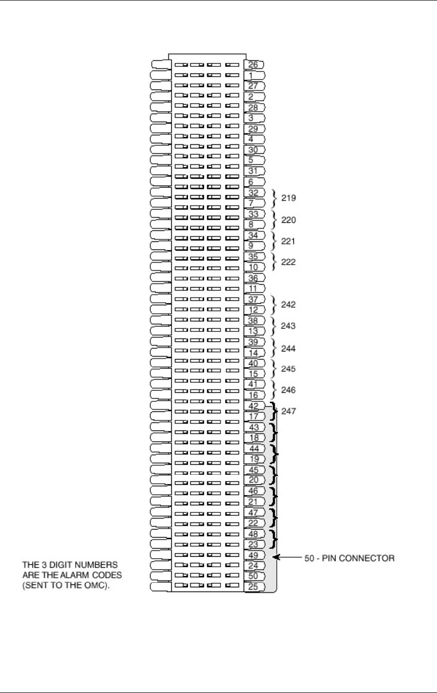
RadioFrame System
Installation
RFN_3.1 Beta 81
Figure 31 Punch Block 1: EAS pinout
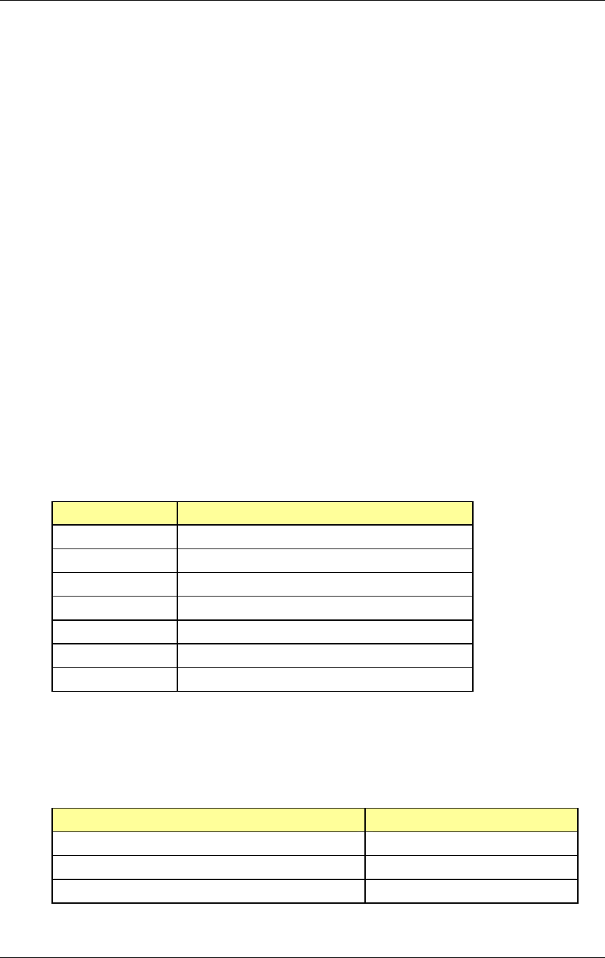
Method of Procedure
Equipment Commissioning
82 RFN_3.1 Beta
5 Equipment Commissioning
The procedures in this chapter describe how to conduct final checkout and
system test procedures for each portion of the iDEN/802.11 RadioFrame System,
including the iDEN Interface, the Power Plant, and the RFS. Following the
successful completion of procedures described in this chapter, the RFS can be
connected to the customer LAN as described in Chapter 6 “Connecting the RFS
to the Customer LAN”.
The procedures in this chapter are to be used in conjunction with troubleshooting
and repair information provided in Chapter 7 Operations and Maintenance and
the RFN document, Field Guide to the RadioFrame System. Together, these
troubleshooting solutions and commissioning procedures provide the necessary
information to isolate failures to a Field Replaceable Unit (FRU). This minimizes
system downtime by quickly returning the site to normal operation.
This chapter’s procedures check system functions and help isolate failures down
to the FRU level. If a failure cannot be isolated after performing these tests, refer
to Chapter 7 “Operations and Maintenance” for technical assistance information.
5.1 iDEN Interface
Perform the following procedures described in the Gen 3 Site Controller System
Manual, Motorola, 68P80801E30-O:
Chapter Procedure Title
5 Final Checkout Final Checkout Setup
Powering the Site Controller Rack
Circuit Breakers
6 System Testing Site Controller Startup Sequence
T1 Connection Test
EAS Alarm Checkout
GPS Status
5.2 Power Plant
Perform the following procedures described in the PEC 127NHL Manual,
PECO II, 438127NHL-IBWS-PD:
Chapter Procedure Title
4 Initial Turn On and Acceptance Test Procedures Complete Operational Checkout
Alarm Tests
BTC Probe Compensation Test

RadioFrame System
Equipment Commissioning
RFN_3.1 Beta 83
Chapter Procedure Title
Test Completion
GPS Status
5.3 RadioFrame System
After installation of all RadioFrame Networks equipment, including verification
that each unit is receiving power, start the System Manager to complete the
installation of the RadioFrame System.
The System Manager automatically downloads information about each
component in the RFS, including assigned IP addresses, sector information, port
connections, and component status, as well as specifying default information that
can be changed, or ‘configured’.
To configure each system component, you will specify a device name, adding
building/site location information for each component. Anytime an RFU port
connection is moved or changed, or when an NPC or APC is moved to another
slot within the same chassis unit (NCU and ACU, respectively), you must restart
the System Manger to download the new information. For other RFS component
changes, restarting is not required, however, RFN recommends validating that
the port change is reflected in System Manager. When new releases of System
Manager are provided, download the new release as described in section 7.1
Upgrading System Software.
NOTE: During configuration, verify that the following information displayed in
System Manager matches the Equipment Inventory. If any changes are made in
System Manager, those changes must also be shown on the Equipment
Inventory or site as-built documentation.
• Physical location
• IP addresses
• Port connections
• Sector locations
5.3.1 Start System Manager
1 Using a 9-pin serial cable, connect a laptop computer to the RS232 port on
the front of the NCU.
2 Start the browser on the laptop, and enter the provided URL to start System
Manager.
The System Manager Home page appears (see the following illustration).
System Manager contains five tabs you select from to set up and monitor the
RadioFrame System:
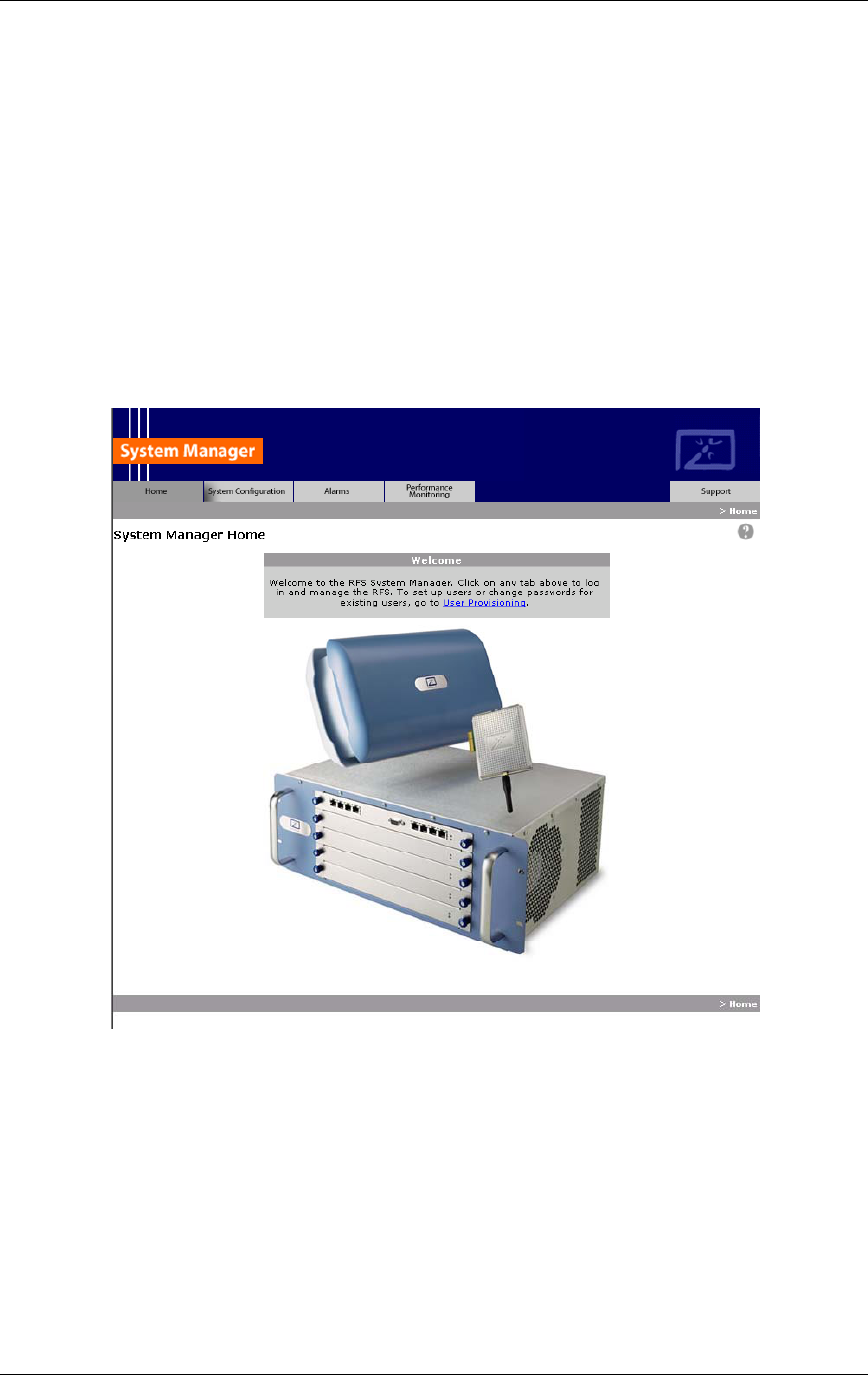
Method of Procedure
Equipment Commissioning
84 RFN_3.1 Beta
• Home—displays a welcome banner and a link for setting up users and
changing the RFS password.
• System Configuration—displays the configuration of each RFS
component, and depicts the location and status of each component,
including the NCU, ACUs, and RFUs.
• Alarms—displays alarm information for each component of the RFS.
• Performance Monitoring—displays real-time performance information
about the RFS.
• Support—displays support information, including online help.
3 To log in, select any tab except the Home tab.
The login page appears (see the following illustration).
4 For User Name, type your RFS user name.
5 For Password, type your RFS password.
6 To save the password so you don’t have to retype it the next time you log in,
check ‘Save this password in your password list’ checkbox.
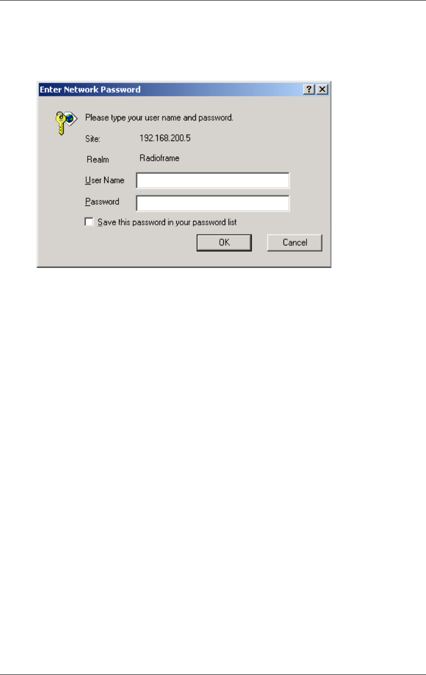
RadioFrame System
Equipment Commissioning
RFN_3.1 Beta 85
7 Select OK.
5.3.2 Navigating the System Configuration
The System Configuration displays icons representing each component included
in the RFS starting with the NCU (see the following illustration). In the following
example, one ACU is connected to the NCU: ACU0 is connected to the NCU via
rear port 1. Generally, ACU0 is the ACU located in the main rack, while ACU1
through ACU7 are remote ACUs. Configuration information for the NCU is
displayed on the left side of the page, including the device name and IP address.
1 To view configuration information for an ACU, select its icon.
A page similar to the NCU page appears displaying configuration information
for the selected ACU and icons for each RFU connected to the ACU. In the
same way you can view the status of each iDEN RadioBlade installed in
every RFU in the RFS by selecting an RFU icon.
2 To return to a previous page, select the component pathname shown at the
top of the tab (System Configuration>NCU>ACU…).
3 To return to the NCU, select the System Configuration tab at any time.
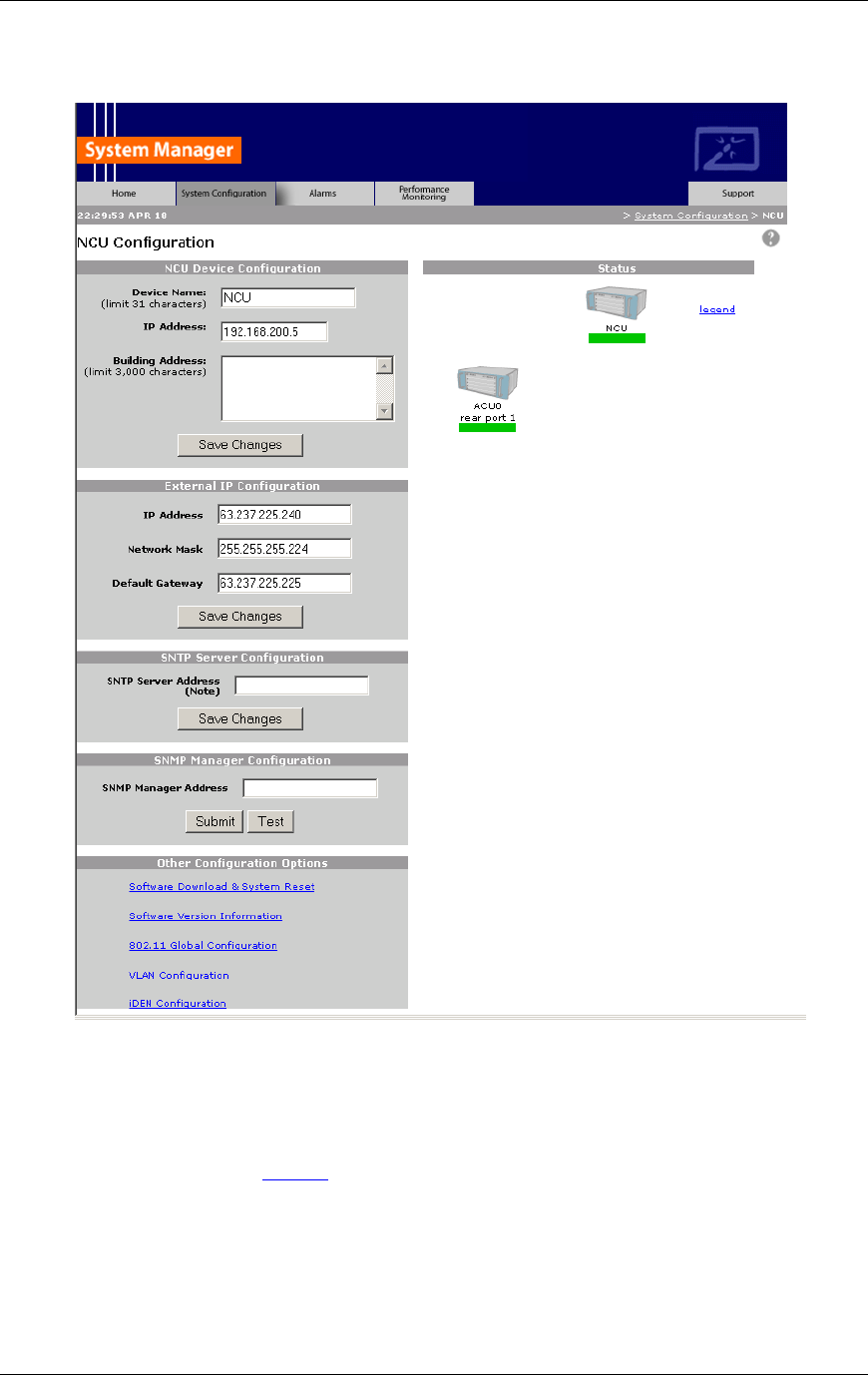
Method of Procedure
Equipment Commissioning
86 RFN_3.1 Beta
5.3.3 Checking the Status of RFS Components
The colored bar beneath each component icon shows the status of that
component. Select legend on any System Configuration page to display the
legend of available status conditions (see the following illustration). The legend
displays the icon representations of each component of the RFS as well as each
available status condition.
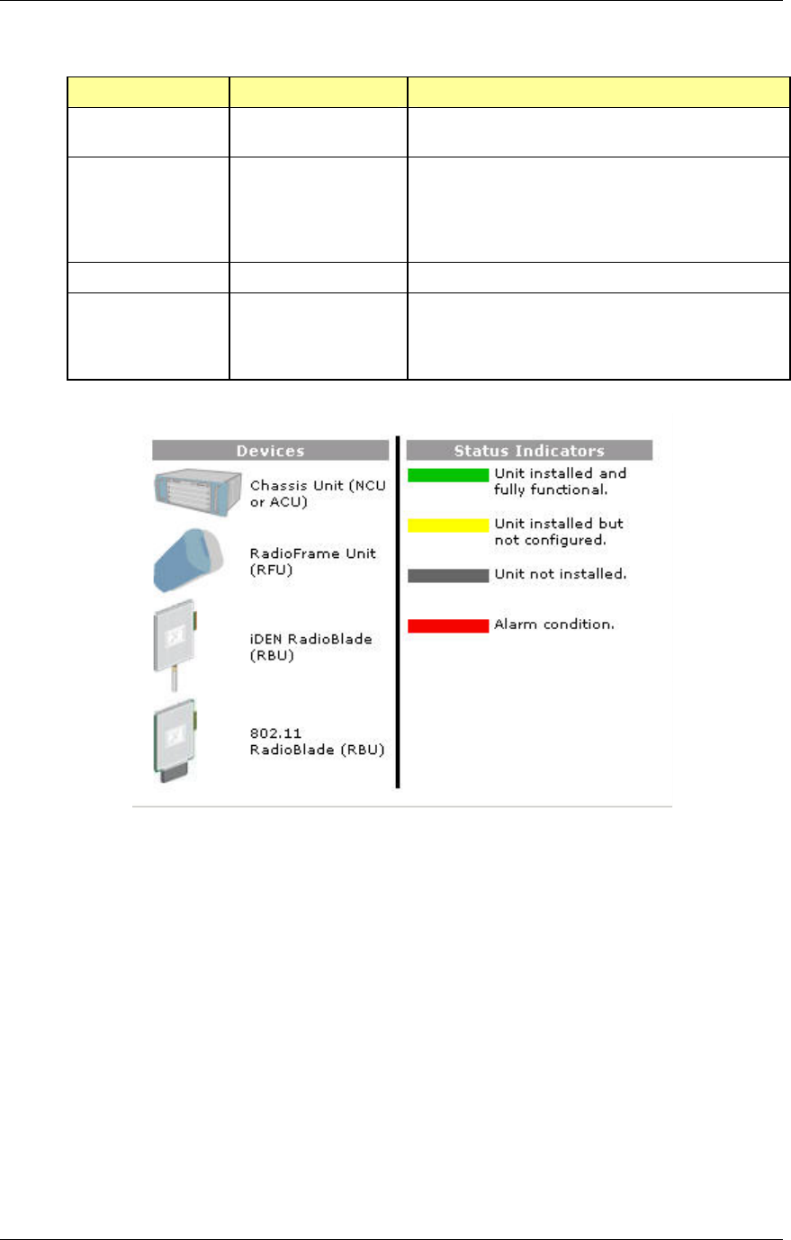
RadioFrame System
Equipment Commissioning
RFN_3.1 Beta 87
Status Indicator Description Action
Green Unit Installed and fully
functional
The component has been installed, configured,
and is operating as it should.
Yellow Unit installed but not
configured
Component has been installed and the System
Manager software is still configuring the
component. When System Manager has finished
startup (10 to 20 minutes), the status will turn to
green, unless there’s a problem with the unit.
Gray Unit not installed Component has not yet been installed.
Red Alarm condition The component has returned an alarm condition.
Refer to Section 7 “Operations and Maintenance”
for specific alarm conditions pertaining to the
component.
5.3.4 Configuring the NCU
The NCU System Configuration page displays the NCU Device Configuration,
including the Device Name, IP Address, and Building Address for the NCU—you
can change this information at any time. This page also displays the External IP
Configuration, the information that systems outside the RFS use to recognize
the RFS, the SNTP Server Configuration, and Other Configuration Options.
1 For Device Name, enter up to 31 alphanumeric characters to uniquely
identify the NCU.
2 The IP Address is assigned during the installation of the RFS. You don’t
need to change the value of this internal address.
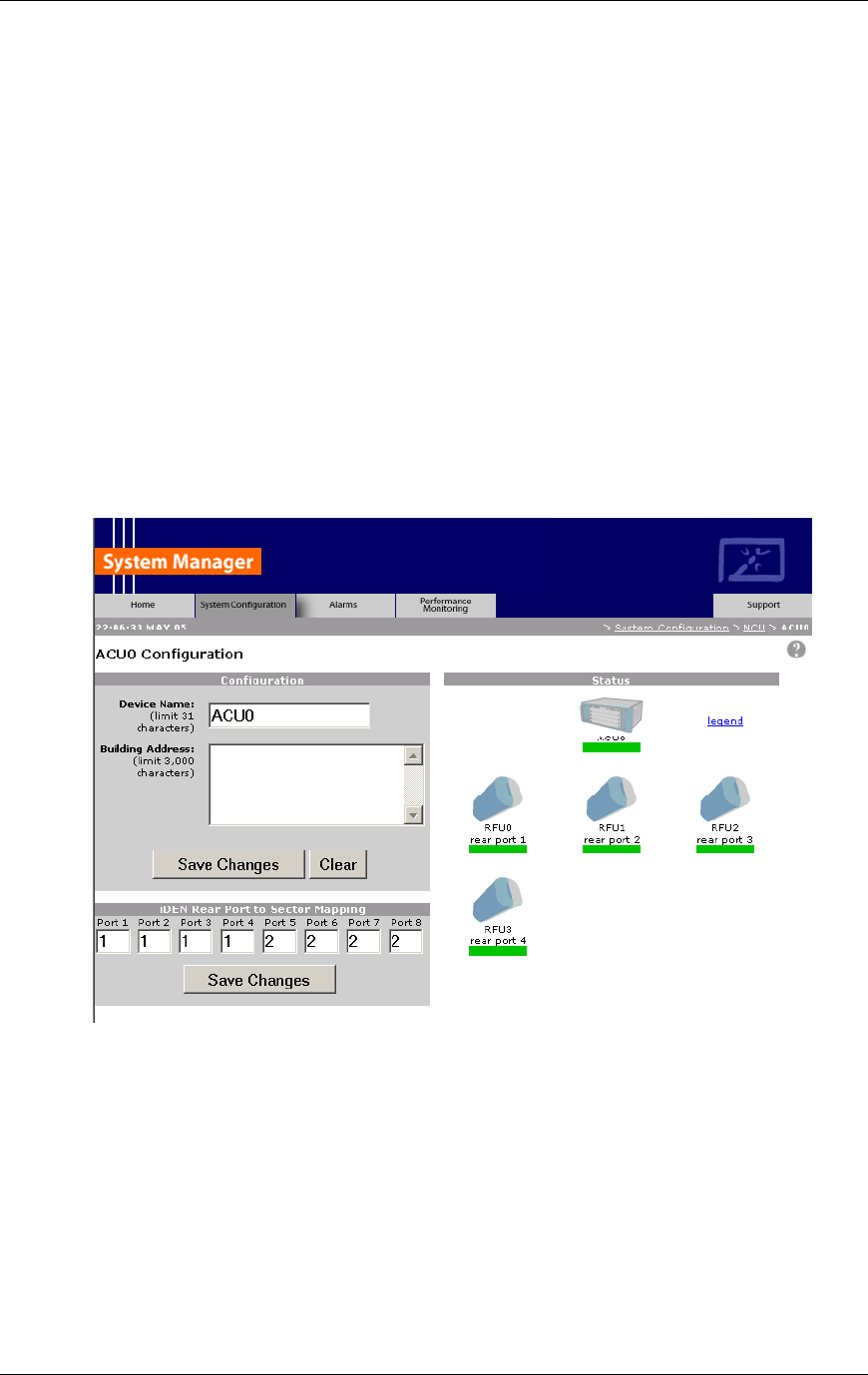
Method of Procedure
Equipment Commissioning
88 RFN_3.1 Beta
3 For Building Address, enter up to 3,000 alphanumeric characters specifying
the location of the NCU.
You can describe the street address, mailing address, building, and other site
information, as well as the building floor, telco closet, and rack to indicate the
location of the unit.
4 Select Save Changes.
5.3.5 Configuring the ACUs
Configure each ACU as you would the NCU, by entering a device name and site
address information (see the following illustration). For each ACU, the System
Configuration page shows the RFUs connected to the ACU (by port) and which
ACU ports are dedicated to which sectors in the iDEN installation. Sector
information is provided to the RFS via the iSC-3 data fill.
1 Navigate to the page of the ACU you want to configure.
2 For Device Name, enter up to 60 alphanumeric characters to uniquely
identify the ACU.
3 For Building Address, enter up to 3,000 alphanumeric characters specifying
the location of the ACU.
You can describe the street address, mailing address, building, and other site
information, as well as the building floor, telco closet, and rack to indicate the
location of the ACU.
4 Select Save Changes or Clear to start over.
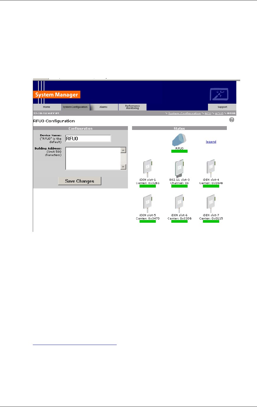
RadioFrame System
Equipment Commissioning
RFN_3.1 Beta 89
5.3.6 Configuring the RFUs
Configure an RFU as you would the NCU or ACU, by entering a device name
and site address information. For each RFU, the configuration page shows the
iDEN RadioBlades and RAPs inserted into the RFU by slot.
1 Select the icon of the RFU you want to configure.
2 For Device Name, enter up to 60 alphanumeric characters to uniquely
identify the RFU.
Use names that are meaningful to the installation.
3 For Building Address, enter up to 3,000 alphanumeric characters specifying
the location of the NCU.
You can describe the street address, mailing address, building, and other site
information, as well as the building floor to indicate the location of the unit.
4 Select Save Changes.
5.3.7 Viewing Hardware and Software Versions
1 On the System Configuration (the ‘NCU Configuration’) page, select the link
Software Version Information in the Other Configuration Options section.
The Software Version Information page depicts component in the RFS, and each
board installed in that component (see the following illustration). For each board,
the page lists:
• HW—hardware version of the component
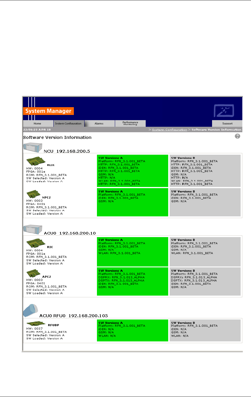
Method of Procedure
Equipment Commissioning
90 RFN_3.1 Beta
• FPGA—Field Programmable Gate Array version (manufacturer defined)
• ROM—software loaded onto board at time of shipment
• SW Selected—currently selected software version, A or B
• SW Loaded—currently loaded software version, A or B
• SW Versions A—Software version
• SW Versions B—Software version
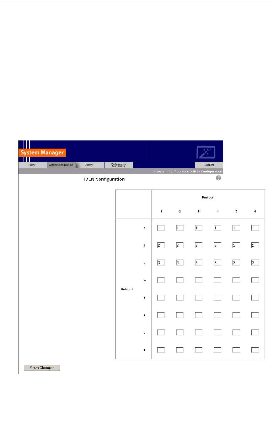
RadioFrame System
Equipment Commissioning
RFN_3.1 Beta 91
5.3.8 Changing the Default iDEN BR Cabinet Position
The RadioFrame System operates as a series of base radios. Each iDEN
RadioBlade in the RFS is assigned a BR ID and sector (1, 2, or 3). Each BR in
the RFS is assigned a default cabinet position in the iSC data fill.
To change the default Cabinet Position:
1 Select the iDEN Configuration link at the bottom of the System Configuration
tab.
The iDEN Configuration page appears (see the following illustration).
2 Enter the new cabinet position for the specified RFS BR(s).
3 Select the Save Changes button to save your changes.

Method of Procedure
Equipment Commissioning
92 RFN_3.1 Beta
5.4 Coverage Validation
Once the components of the RadioFrame System have been configured, use
iFTA-software, a laptop and an iDEN handset to check for regions of low signal
strength. If increasing the transmit power from one or more local RFUs does not
resolve the problem, adding another RFU is the surest remedy.
5.4.1 Detailed Building Plans—RF Modeling
Testing by RFN has shown that simple Linear Attenuation Models (LAM) as
discussed in COST 231, Chapter 4 section 4.7 “Indoor Propagation Models” work
well provided they are used on a floor-by-floor basis. An attenuation coefficient of
0.62dB/m is recommended for dense, single-floor propagation, but this can
double if concrete walls are present.
5.4.2 Measurement-based Estimate
A battery-powered test transmitter can be moved between each RFU location
and a handheld signal strength meter used to monitor RSSI. This method can be
useful when RF penetration is desired through suspect walls or where wall
construction data is lacking. Generally, this method provides good agreement
when it is used to identify regions of poor coverage rather than to establish
sufficient coverage zones. This is because it is usually inconvenient to duplicate
an RFUs’ position during initial coverage surveys.
5.4.3 Floor Plan Estimate
Oftentimes, only simple floor plans are available for the building in which the
RFUs are to be installed. Without specifics about the building construction, such
as interior wall, floor and ceiling construction, propagation models are of limited
value. A measurement-based approach (discussed earlier) works well, but for
simple buildings, installing RFUs at the candidate locations and then testing the
results will likely be adequate. If regions of poor coverage are found, transmit
power can be increased or if necessary, additional RFUs added.
5.5 Site Acceptance Guidelines
5.5.1 Site As-Built Documentation
As-built documentation consists of the original site development documentation
with post-installation information. On the job, installers use site development
documentation for reference, to make notes, and to document completion of
each step of the installation.

RadioFrame System
Equipment Commissioning
RFN_3.1 Beta 93
Conduct an onsite walk through to verify that the following Site Development
Punch List items have been properly installed. This inspection ensures that the
site installation meets quality standards.
• Grounding
- buss bar OK (optional)
- NCU/ACU rack(s)
- rectifier rack
- battery shelf (GNB)
• Peco II Rectifier Voltages (measured voltages)
- float voltage
- equalize voltage
- high voltage
- low voltage
- low voltage pickup
- low voltage drop out
• Battery Information (for batteries 1 through 8)
- Plant voltage
- Measured voltage
- connections corroded
- terminals greased
- signs of leakage
• Main Rack
- EAS revision complete
- CSU grounded
- 5 MHz ‘A’ split with ‘T’
- 5 MHz ‘B’ split with ‘T’
• T1 Information, Primary and Secondary
- T1 circuit ID#
- T1 surge arrestor installed/grounded
- T1 repeater shelf / cfl cabinet location
- T1 level at extended demarc (RJ48 x jack)
• Summary
- log book at site with recent entry
- outstanding issues/punch list items for site
- defective equipment found/replaced
5.5.2 Site As-Built Acceptance Test Procedures
Complete the test procedures described in this section to record the site as built.
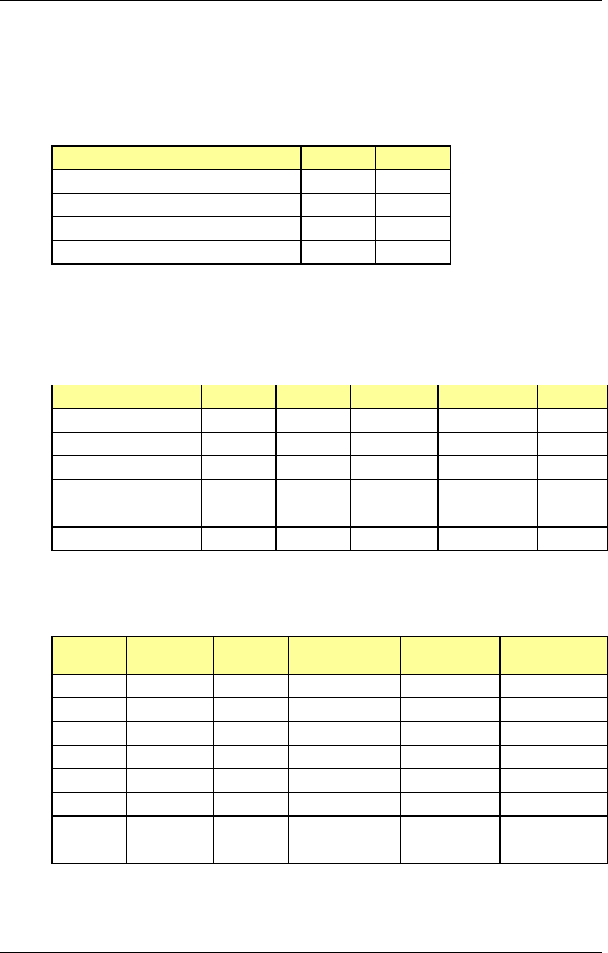
Method of Procedure
Equipment Commissioning
94 RFN_3.1 Beta
5.5.2.1 Grounding
Record the following grounding information. For any unacceptable item, take
corrective action and record what occurred, or record the item for the next site
visit.
Yes No
Buss Bar O.K. (optional)
NCU/ACU rack(s)
Rectifier rack
Battery shelf (GNB)
5.5.2.2 Power Plant
Measure and record the following voltages for the Peco II rectifier. (For further
information, refer to the product specification information provided by Peco II,
Inc., the rectifier manufacturer: Small DC Power Systems, Spec. No. 127NHL.)
GNB Dynasty
Float voltage Suggested -54.0 vdc -54.8 vdc Measured at
Equalize voltage Suggested -56.4 vdc -58.4 vdc Measured at
High voltage Suggested -56.0 vdc -58.0 vdc Measured at
Low voltage Suggested -43.0 vdc -43.0 vdc Measured at
Low voltage Pick-up Suggested -46.0 vdc -46.0 vdc Measured at
Low voltage drop-out Suggested -42.0 vdc -42.0 vdc Measured at
5.5.2.3 Battery
Record the following information for each of the eight batteries.
Plant
Voltage
Measured
At
Connections
Corroded (Y/N)
Terminals
Greased (Y/N)
Signs of
Leakage (Y/N)
Battery 1
Battery 2
Battery 3
Battery 4
Battery 5
Battery 6
Battery 7
Battery 8
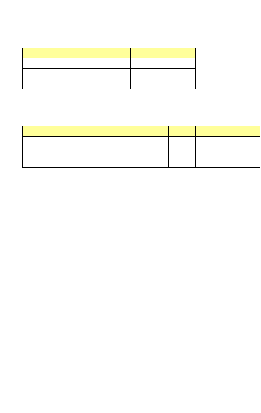
RadioFrame System
Equipment Commissioning
RFN_3.1 Beta 95
5.5.2.4 Main Rack
Record the following information for the main rack.
Yes No
CSU grounded
5 Mhz “A” split w/ “T”
5 Mhz “B” split w/ “T”
5.5.2.5 T1 Line
Record the following information for the T1 line.
T1 circuit ID # Primary Secondary
T1 surge arrestor installed/grounded Yes No
T1 repeater shelf/cfl cabinet location Inside Outside
T1 level at extended demarc (RJ48x jack) +/- dbsx Voltage
5.5.3 RadioFrame System As-Built Documentation
As-built documentation for the RadioFrame Networks equipment includes the
following:
• Equipment inventory
• Cabling pathways
• Floor Plan with site configuration and component locations
5.5.3.1 Equipment Inventory
The final Equipment Inventory should show the following information for the RFS
components installed:
• Part number
• Serial number
• Rack position (NCUs and ACUs only)
• Card position (APCs and NPCs only)
• RFU location (including floor and sector)
• iDEN RadioBlade and RAP positions in RFU
• Universal Repeater Unit (URU) location
• MAC Address
• IP Address

Method of Procedure
Equipment Commissioning
96 RFN_3.1 Beta
• Channel (RAPs only)
• Port connections between RFS components
5.5.3.2 Cabling Pathways
A schematic showing the route of each cable run at the site. For each cable run,
list the following:
• Cable length
• Cable type
• Connector types (both ends)
• Cable labeling completed per specs
• Port Connections
• Continuity test results
• Distance test results
5.5.3.3 Floor Plan/Site Drawing
Use a floor plan or site drawing to denote the location of the following on each
floor of the building:
• Main rack
• Remote ACUs, including power source
• RFUs
• URUs, including power source
5.5.4 RadioFrame System Acceptance Test
During installation, each component of the RFS is verified for power and
connectivity. Assuming that each system component—NCU, ACU, RFU, and
URU—has been properly installed and is receiving power, double check that all
Power, Status, Link and Activity LEDs throughout the system are lit and are
green. For any other condition on any system component or connection, refer to
section 7.3 Corrective Maintenance, subsection 7.3.3 RadioFrame System for
troubleshooting procedures.
5.6 RadioFrame System Functionality Test
This section describes the procedures that are used to test and verify the
RadioFrame Networks equipment. This certification process ensures proper
operational performance and verifies the integrity of the following services:

RadioFrame System
Equipment Commissioning
RFN_3.1 Beta 97
• RFS iDEN functionality test:
- iDEN 3:1 Interconnect Voice
- iDEN 6:1 Private and Group Dispatch
- iDEN Packet Data
- iDEN Short Message Service
• Rectifier & AC power alarms
• iSC-3 functionality test
Once the RFS System Functionality Testing is successfully completed, the RFS
can be connected to the Customer LAN, and system testing for the WLAN may
be completed.
5.6.1 RadioFrame System iDEN Functionality Test
Test and verification of the RadioFrame System will specifically validate the
following aspects of the above services:
• Voice quality for 3:1 Interconnect Voice
• Voice quality for 6:1 Private Group Dispatch Voice
• Call setup reliability for 3:1 Interconnect Voice
• Call setup reliability for 6:1 Private and Group Dispatch Voice
• Call stability for all of the above voice services
• Voice capacity
• Connection quality, stability, delay and perceived throughput for the Packet
Data service
• Connection setup reliability for Packet Data
• Idle SQE quality and variation
• Call up SQE quality and variation
• Short Message Service
• Handover and cell reselection
• Overall system stability (includes recovery from T1, iSC-3 and GPS outages)
• Performance will also be validated by collecting at least one week of
performance statistical data
5.6.1.1 Interconnect & Dispatch Setup & Voice Quality
Interconnect and Dispatch voice quality will be assessed by evaluating voice
links as described in Tables 1, 2, and 3. RSSI and SQE measurements will be
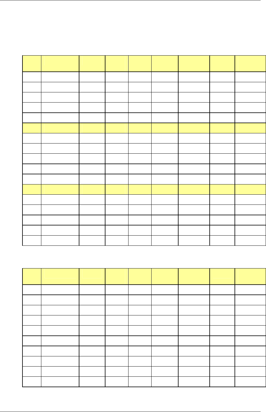
Method of Procedure
Equipment Commissioning
98 RFN_3.1 Beta
made via the handset. These tests are to be performed on a selected sample set
of links.
Table 1 Interconnect Call Quality, Setup and Stability
Test
#
MOP/PSTN Carrier # RSSI
(dbm)
SQE
(dbm)
Quality
(1-5)
Distance
(ft)
Sector Duration
(Min)
1 50 2
2 50 2
3 50 2
4 50 2
5 50 2
PSTN/MT
1 50 2
2 50 2
3 50 2
4 50 2
5 50 2
MO/MT
1 50 2
2 50 2
3 50 2
4 50 2
5 50 2
Table 2 Group Dispatch Call Quality, Setup, and Stability
Test
#
MO/MT Carrier # RSSI
(dbm)
SQE
(dbm)
Quality
(1-5)
Distance
(ft)
Sector Duration
(Min)
1 50 2
2 50 2
3 50 2
4 50 2
5 50 2
6 50 2
7 50 2
8 50 2
9 50 2
10 50 2
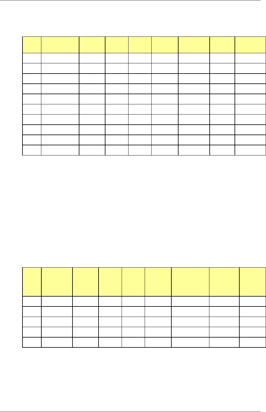
RadioFrame System
Equipment Commissioning
RFN_3.1 Beta 99
Table 3 Private Dispatch Call Quality, Setup, and Stability
Test
#
MO/MT Carrier # RSSI
(dbm)
SQE
(dbm)
Quality
(1-5)
Distance
(ft)
Sector Duration
(Min)
1 50 2:30
2 50 2:30
3 50 2:30
4 50 2:30
5 50 2:30
6 50 2:30
7 50 2:30
8 50 2:30
9 50 2:30
10 50 2:30
5.6.1.2 Packet Data Service Connection and Latency
The Packet Data service will be tested and verified on the RadioFrame System.
Motorola’s Packet Data Applet will be used to connect to the RFN customer’s
Packet Data network over the RadioFrame System, using a tethered connection
with a Motorola handset.
Several samples of PING requests will be sent to a Router in the RFN customer’s
Packet Data network and average round trip times will be recorded to measure
latency. The table below presents the data to be collected for each ping using the
RFS. These tests shall be performed using Windows 2000 OS and the timeout
for each ping reply shall be set to 2000 milliseconds.
Table 4 Packet Data Latency over the RFS (Ping –n 100 –w 2000 xx.xxx.xxx.x )
T
est # Handset Carrier # RSSI
(dbm)
SQE
(dbm)
Ping
(No. of
Echos)
Router (IP
Address)
Average
Round
Trip Time
(msec)
Packet
Loss
(%)
1 100 xxx.xxx.xxx.x
2 100 xxx.xxx.xxx.x
3 100 xxx.xxx.xxx.x
4 100 xxx.xxx.xxx.x
5 100 xxx.xxx.xxx.x
The following table presents (baseline) data collected for each ping using a
Motorola Macrocell in order to average Round Trip time over the RFS versus
over Motorola standard Base Station equipment.
Method of Procedure
Equipment Commissioning
100 RFN_3.1 Beta
Table 5 Packet Data Latency over Motorola EBTS
T
est # Handset Carrier # RSSI
(dbm)
SQE
(dbm)
Ping
(No. of
Echos)
Router (IP
Address)
Average
Round
Trip Time
(msec)
Packet
Loss
(%)
1 100 xxx.xxx.xxx.x 0
2 100 xxx.xxx.xxx.x 0
3 100 xxx.xxx.xxx.x 0
4 100 xxx.xxx.xxx.x 0
5 100 xxx.xxx.xxx.x 0
5.6.1.3 Short Message Service
The Short Message Service (SMS) will be tested and verified by initiating the
delivery of a voice mail notification to the handset via one of the iDEN
RadioBlade links. Complete the following only if such testing is available via the
RFN customer’s web site.
1 Navigate on a network connection to the Internet.
2 Navigate to the RFN customer’s web site in the web browser.
3 On the RFN customer’s web site, enter the 10-digit phone number of the test
phone in the messaging field, which will display the mobile messaging page.
4 Enter a short text message into the field for message, and also enter a
subject in the subject line.
5 Press the Send button.
The message should appear on the test phone within a few minutes.
5.6.1.4 Handover and Cell Reselection
Handover and Cell Reselection shall be tested and verified that mobiles on the
RFS successfully handoff to the macro-cellular network during an interconnect
call. These tests shall also verify that mobiles on the RFS perform successful cell
reselection when in an idle state. The following table presents the data to be
collected for the handover and reselection tests.
Table 6 Handover & Idle Mode Reselection
Test
#
Handover (Mobile #) Carrier # from (HEX) Carrier # to (HEX)
1
2
3
RadioFrame System
Equipment Commissioning
RFN_3.1 Beta 101
Cell Reselection (Mobile #)
1
2
3
5.6.1.5 Interconnect Connection Stability and SQE Performance
A single link for 3:1 Interconnect will be maintained for 30 minutes each. The
following table presents the data to be collected for each selected link. The iDEN
Field Test Application (IFTA) shall be used in “Single Cell” mode to observe the
SQE performance and plotted over time.
Table 7 Interconnect Connection Stability
Interconnect #1 Carrier # RSSI (dBm) SQE (dB) Sector Duration (min)
30
Interconnect #2
30
Interconnect #3
5.6.1.6 Dispatch Connection Stability
To verify Dispatch connection stability, a Dispatch (private or group) call will be
maintained for several minutes. The following table presents the data to be
collected for each dispatch call.
Table 8 Dispatch Connection Stability
Dispatch #1 Carrier # RSSI (dB) SQE (dB) Sector Quality
(1-5)
Duration
(min)
3
Dispatch #2
4
Dispatch #3
5
5.6.1.7 Idle SQE Testing and Validation
To validate SQE performance, the following test shall be conducted:
1 Control Channel SQE:

Method of Procedure
Equipment Commissioning
102 RFN_3.1 Beta
The iFTA tool shall be used in “Single Cell” mode and idle RSSI and SQE
values shall be recorded for control channel for at least one hour per sector,
while the mobile remains fixed.
A second test per sector shall be performed in “Single Cell” mode while
walking the facility for approximately 15 minutes.
2 SQE and RSSI Variation Test for all 4 iDEN Channels
In this test, the iFTA shall be placed in “Monitor Many” mode and idle RSSI
and SQE values shall be recorded for all iDEN channels for at least one hour
per sector while the mobile remains fixed.
These tests shall be conducted over a period of 3 days and minimally 3 times in
a 24-hour period.
5.6.1.8 System Self-Recovery Test
The following test is to determine the RFS’ ability to recover from various iSC-3
conditions.
1 Loss of T1
While the RFS is operating, the T1 connection to the iSC-3 will be
disconnected for one minute and then reconnected. System recovery will be
monitored and validated by placing a successful call on each sector.
2 iSC-3 Power Loss
While the RFS is operating, the iSC-3 shall be power cycled and system
recovery will be monitored and validated by placing a successful call on each
sector.
3 Loss of GPS
While the RFS is operating, the GPS connection to the iSC-3 will be
disconnected until all Satellites are lost and then reconnected. System
recovery will be monitored and validated by placing a successful call on each
sector.
4 New data-fill download
System recovery will be verified by pushing a new data-fill download to the
iSC-3.
5.6.1.9 Packet Data Stability and Throughput
The Packet Data stability and throughput to the Internet will be verified. A
tethered Packet Data connection will be set up on a laptop and speed tested by
using the www.bandwidthplace.com website. This continuous download of data
stream will validate system stability and help to quantify user experience of
Packet Data over the RadioFrame System.

RadioFrame System
Equipment Commissioning
RFN_3.1 Beta 103
5.6.1.10 Validation of ‘Unable to Key BR’ Alarm
While the RFS is operating, any system component, from the NCU to the RFU,
will be disconnected, and the OMC will be monitored to validate the generation of
the “Unable to Key BR” alarm by the RFS.
The RFS provides fault alarming and isolation within System Manager for
individual components, which consists of detecting catastrophic faults that
prevent an RFS component from responding to a periodic “ping”. All fault alarms
generated by the RFS are received at the OMC via the iSC. The “Unable to Key
BR” alarm will appear at the OMC as minor, major, or critical as follows (for more
information about alarms, refer to section 7.5 Alarm Resolution Procedures):
‘Unable to Key BR’ alarm severity Indication
minor An iDEN RadioBlade or 802.11b RAP has failed.
major An RFU has failed.
critical A card in a chassis unit has failed (except for the RLIC,
which is responsible for returning the alarm information.)
5.6.2 Rectifier & AC Power Alarms
For information on conducting an Rectifier functionality test, refer to the Peco II
document: Peco II 127HNL.
5.6.3 iSC-3 Functionality Test
For information on conducting an iSC-3 functionality test, refer to the Motorola
document: Gen 3 Site Controller System Manaual, 68P80801E30-O.
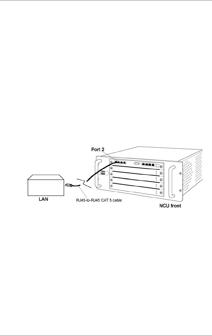
Method of Procedure
Connecting to the Customer LAN
104 RFN_3.1 Beta
6 Connecting the RFS to the Customer LAN
Once the RadioFrame System has been installed, commissioned, and all iDEN
Acceptance Test and System Functionality procedures have been successfully
completed, the RFS can be connected to the Customer LAN. Once the LAN has
been physically connected, the RFS must be globally configured to support the
LAN. Individual RAPs can also be configured, overriding certain global
configuration options.
6.1 Connect the NCU to the Customer LAN
In an 802.11b installation, RAPs are installed in each RFU supporting the WLAN.
Once the RFS has been physically connected to the LAN, use the System
Manager to configure the RFS to support the WLAN.
1 Connect Port 2 on the front of the NCU to the customer’s local area network
using an RJ45-to-RJ45 CAT 5 cable (see the following illustration).
Figure 32 Connect Port 2 on the front of the NCU to the customer’s LAN.
6.2 Configure the RFS Global 802.11 Services
This section describes how to configure the RFS global, or system-wide, 802.11
configuration settings. First, start the System Manager, then configure the
following five items:
• Service Set Identity (mandatory)
• WEP Encryption (optional)
• Enhanced Security (optional)
• User Access Control (optional)
• Add/Remove MAC Addresses (optional)
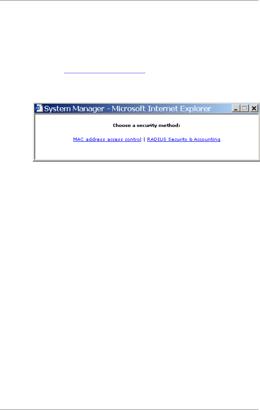
RadioFrame System
Connecting to the Customer LAN
RFN_3.1 Beta 105
1 Start System Manager and log in to the RFS.
Start your browser, and enter the provided RFS URL to start System
Manager. Enter your User Name and Password to log in to the RFS.
2 Select the System Configuration tab.
3 Select the 802.11 Global Configuration link under Other Configure Options.
The following screen appears. You must choose a security method for the
RFS, or the RFS will not work.
4 Select “MAC address access control”.
The 802.11 Global Configuration page appears (see the following illustration).
The 802.11 settings are divided into five groups:
• SSID
• WEP Encryption
• Enhanced Security
• User Access Control
• Add/Remove MAC Addresses.
When you make changes to any of these five settings, you must save the
changes for that section using the Save Changes button for that setting.
5 For SSID, enter up to 32 alphanumeric characters to identify the Service Set
Identity for the RFS, and select Save Changes to save your changes.
You must enter an SSID in order for the RFS to have 802.11 capabilities.
Typically, the SSID reflects the owner of the RFS. By default, the owner is
RFN Customer. For more information, refer to section 6.2.1 Service Set
Identity (SSID).
6 For WEP Encryption, RFN recommends that you set Encryption to “On”. In
this case, you must also define the four WEP keys.
To enter a WEP Key, first select the radio button next to the text box of the
WEP key you want to enter or change. Enter each WEP key in hexadecimal
format consisting of five pairs of hex digits. Five pairs of hex digits form a 40-
bit binary string, which is the standard length of a WEP key. Only one WEP
Key can be selected at a time (the radio button is selected). Then, choose
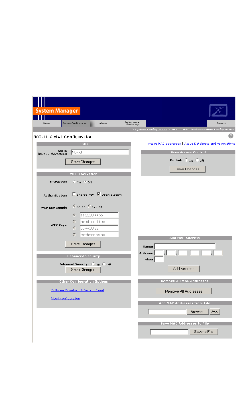
Method of Procedure
Connecting to the Customer LAN
106 RFN_3.1 Beta
one of the four keys to be used for RAP identification (select the radio button
of the key you want to use).
For Shared Key Authentication, RFN recommends that you leave this
option disabled, that is, do not select the option. When you have set all the
WEP Encryption options you want, select Save Changes.
Refer to section 6.2.2 WEP Encryption for more information on using WEP
Encryption settings.
Figure 33 Each global 802.11 configuration setting has a separate “save” button.

RadioFrame System
Connecting to the Customer LAN
RFN_3.1 Beta 107
7 For Enhanced Security, RFN recommends that you select “On” to prevent
RAPs from broadcasting their SSIDs. Then select Save Changes.
For more information, refer to section 6.2.3 Enhanced Security for more
information on using this setting.
8 For User Access Control, RFN recommends that you select “On” to control
which devices will have access to the customer LAN via the RFS. Then select
Save Changes.
For more information, refer to section 6.2.4 User Access Control for more
information on using this setting.
9 For Add MAC Address, enter the MAC address of each device that will be
authorized to the use the customer LAN. You can enter MAC addresses one
at a time, or copy them from a database or other file (Add MAC Addresses
from file). You can also remove the entire list of MAC addresses (Remove
All MAC Addresses), or save the list of MAC addresses to a file (Save MAC
Addresses to File).
For more information, refer to section 6.2.5 Add/Remove MAC Addresses for
more information on using these options.
6.2.1 Service Set Identity (SSID)
The only mandatory RFS 802.11b configuration setting is the Service Set Identity
(SSID). The SSID must be configured in all installations where 802.11b
RadioFrame Access Points are installed. If the SSID is not configured, the
802.11b capability will not be available.
The SSID is necessary because, unlike wired LANs, a device which is part of an
802.11 LAN may be within radio range of multiple “groups” of 802.11 stations. In
order to isolate stations in one group from stations in another group, the SSID
was created. It is an 802.11-only construct, which does not exist for any other
type of LAN. The SSID identifies a collection of 802.11 stations for the purpose of
communication as a group.
The SSID is 1 to 32 characters in length. Typically, the SSID reflects the owner of
the RFS. By default, the SSID is ‘RFN Customer’. This way, users can
distinguish their LAN from any other 802.11 LAN which might physically overlap
their area.
For example, the SSID “RFN_Customer_Marketing” could provide the Marketing
department at the RFN customer with its own distinct wireless LAN. Other
departments within the RFN customer, such as “RFN_Customer_Operations”,
might be in close proximity to the Marketing department. The staff in the two
departments would both have 802.11 access to the company LAN, but their
access would be provided via different RAPs, based on which SSID they use.

Method of Procedure
Connecting to the Customer LAN
108 RFN_3.1 Beta
6.2.2 WEP Encryption
The Wired Equivalent Privacy (WEP) encryption technology is defined in the
IEEE 802.11 standard, and is intended to provide the same quality of privacy and
access control for an 802.11 LAN as is provided for a wired LAN. That is, a WEP-
protected 802.11 is should be no easier to infiltrate or eavesdrop than would be
on a wired LAN.
Any LAN (wired or wireless) can be made more secure and private by applying
additional security measures (such as encryption, centralized strong
authentication, firewalling, etc.). The difference between a wired LAN and a
wireless LAN, however, is that without including encryption of user traffic and
encryption-based access control, a wireless LAN is inherently less secure than a
wired LAN, all other things being equal.
6.2.2.1 Encryption (On/Off)
WEP encryption is enabled or disabled by selecting “On” or “Off,” respectively.
When “Off” is selected, all other items related to WEP encryption are disabled
(WEP Keys and Shared Key Authentication), and need not be configured. When
“On” is selected, then the WEP keys must be entered.
6.2.2.2 Shared Key Authentication
When Shared Key Authentication is enabled, or “checked,” the RAPs will require
client devices (such as laptop computers) to prove their authenticity by answering
a challenge from the RAP. This challenge (authentication protocol) can be
answered correctly only if the client device “knows” the WEP keys configured into
this RFS.
NOTE: RFN does not recommend the use of Shared key authentication,
because the messages used to accomplish this authentication may provide
information to eavesdroppers as an aid in cracking the WEP encryption on future
messages. The ability to enable or disable Shared Key Authentication is provided
mainly for compatibility purposes. Some client adapters may require Shared Key
Authentication whenever WEP encryption is enabled. If this is not the case with
the client adapters used in your location, then it is best to leave this setting
disabled. This does not compromise security, however, because with WEP
encryption enabled, the RAP will not accept traffic from 802.11 client devices
unless the traffic is encrypted.
6.2.2.3 WEP Keys
When WEP Encryption is enabled, you must enter values for the four WEP keys
in order for the RFS 802.11 implementation to function. WEP Keys are used to
encrypt 802.11 traffic that is transmitted by a RAP.
Each WEP Key has a radio button. When you select the radio button, you can
enter, change, or delete information for that key only. Each WEP key consists of

RadioFrame System
Connecting to the Customer LAN
RFN_3.1 Beta 109
five pairs of hex digits forming a 40-bit binary string, which is the standard length
of a WEP key.
Only one WEP Key can be selected at a time. The selected key is used to
encrypt 802.11 traffic that is transmitted by a RAP. However, any of the four keys
may be used by client devices for their transmissions. The determination of which
key is used by a client device is performed at the client device, usually in a
manner similar to the way the RAP is configured.
6.2.3 Enhanced Security
Enhanced Security provides another layer of protection for the RFS 802.11
implementation. When enabled, or “On”, this setting prevents RAPs from
broadcasting their SSID information. This helps to prevent unwanted users from
accessing the customer’s WLAN. When disabled, or “Off”, any system can ‘see’
the SSID of RAPs in the customer WLAN.
6.2.4 User Access Control
The RFS provides the ability to restrict access to the customer LAN to certain
pre-authorized devices. RFN recommends setting the User Access Control
option to “On” to provide a means to identify those devices that are authorized to
communicate over the customer’s LAN via the RFS. When this option is disabled,
set to “Off”, any client device may associate with the RFS.
Devices are identified by a number that is programmed into the 802.11b network
interface installed in the device. For instance, laptop PCs typically use a PCMCIA
card plugged into the laptop’s PCMCIA bay to access an 802.11 network. Every
802.11b PCMCIA card comes from the manufacturer with a unique serial number
programmed into it. No two 802.11b devices are ever manufactured with the
same serial number.
In IEEE 802 networking terminology, this serial number is called the MAC
address (Media Access Control address), an addressing mechanism that is
present in all types of IEEE 802 LANs. The MAC address is typically represented
as six sets of hexadecimal (base 16) numbers, with two hexadecimal digits in
each set. The following is an example of how a MAC address may be written:
00:04:16:A3:29:B7
Authorized MAC addresses/devices are listed below the User Control option. To
learn how to add and remove MAC addresses, read the following section 6.2.5
Add/Remove MAC Addresses. When you are done adding and removing MAC
addresses, you’ll select the Save Changes button under User Access Control.
6.2.5 Add/Remove MAC Addresses
Start by collecting a list of MAC addresses for all user devices that will be
authorized to access the customer’s LAN via the RFS 802.11. It is best to keep a

Method of Procedure
Connecting to the Customer LAN
110 RFN_3.1 Beta
permanent list (on paper, in a spreadsheet, or other computer storage) that
includes each MAC address and a description of the device, including the name
of the person who owns the device, etc. Also refer to section 6.4 Viewing WLAN
User/RAP Associations, later in this chapter.
6.2.5.1 Adding MAC Addresses
MAC addresses are added to the list of authorized client devices in one of two
ways: one, you can enter the addresses one at a time, or two, you can enter the
MAC addresses into a text file and “upload” this list into the MAC address
database.
To add an individual MAC address, enter it in the box labeled Address. Enter
each MAC address in the format described above, that is, six pairs of
hexadecimal digits (for example 00:04:16:A3:29:B7). The alphabetic values of
hexadecimal digits—A,B,C,D,E,F—may be in either upper case or lower case.
For Name, enter a meaningful device name or identifier, or the name of the
person who owns the device, then select Add Address.
To add MAC addresses from a file, either enter the file name under Add MAC
Addresses from File (including drive letter and full pathname), or select the
Browse… button to locate the file. Then, select Add. This appends the MAC
addresses from the file to any other MAC addresses already entered into System
Manager.
TIP Add one or two individual MAC addresses, then save those MAC addresses
to a file (see “Saving MAC Addresses” later in this section). Then open the text
file and copy the saved address(es) to a new line in the file, and edit each line to
specify a different client device and MAC address. This way, you can create your
list of authorized devices, save the file as a backup, and upload the file into the
System Manager knowing that the format of the text file will be acceptable to the
System Manager.
6.2.5.2 Removing MAC Addresses
To remove a MAC address, select the delete option listed next to the MAC
address you wish to remove.
To remove all MAC addresses, select the Remove All Addresses button under
Remove All MAC Addresses.
6.2.5.3 Saving MAC Addresses
When all additions or removals have been completed, select the Save Changes
button at the bottom of the User Access Control section. This will record the
MAC addresses and the User Access Control setting and activate them.
To save the entire list of MAC addresses to a file, enter a file name in the text
box under Save MAC Addresses to File, then select the Save to File button.
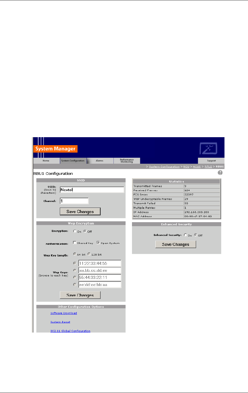
RadioFrame System
Connecting to the Customer LAN
RFN_3.1 Beta 111
6.3 Configuring an Individual RAP
RadioFrame Access Points (RAPs) provide the 802.11b wireless interface
between the RFS and the corporate local area network (LAN). Typically, all RAPs
in the RFS are configured at one time using the 802.11 Global Configuration
options. These global settings can be overridden by changing configuration
information for individual RAPs. Individual RAPs can also be isolated from further
global changes as well.
NOTE: WEP Encryption and Enhanced Security settings override global 802.11
settings. Typically, changing these settings is done to isolate the RAP for testing.
1 Using the System Configuration tab, drill down to the RFU that contains the
RAP(s) you want to configure, and then select the RAP icon to display its
configuration page.
2 For SSID, either leave the globally configured SSID name as it is, or enter up
to 31 alphanumeric characters to change it.

Method of Procedure
Connecting to the Customer LAN
112 RFN_3.1 Beta
The SSID you enter must be a valid SSID that is recognized by System
Manager.
3 For Channel, type 1, 6, or 11 to specify the channel to be used by the RAP.
At the time of shipment, all RAPs are set to Channel 6 by default. Channel
numbers can only be changed at the RAP level—channels cannot be
changed using global settings. If a 3-channel frequency plan is implemented,
RFN recommends using channels 1, 6, and 11 (in countries where these
channels are permitted).
4 Select ‘Save Changes’ to save the SSID and Channel settings.
5 When WEP Encryption is disabled or “Off”, all other items related to WEP
encryption are disabled (WEP Keys and Shared Key Authentication). When
“On”, a WEP Key other than the globally configured WEP key can be
selected. Also, Shared Key Authentication can be enabled or disabled,
“checked” or “unchecked” respectively. For more information about Shared
Key Authentication, refer to section 6.2.2.2 Shared Key Authentication.
RFN recommends that RAP WEP Encryption settings be set globally rather
than individually.
RAP WEP Encryption changes remain until changes are made to the global
802.11 settings.
6 Statistics lists information about the functioning of the RAP, including:
Statistic Description
Transmitted Frames Number of frames transmitted by the RAP
Received Frames Number of frames received by the RAP
FCS Errors Number of FCS errors
WEP Undecryptable Frames Number of frames that could not be unencrypted
Transmit Failed Number of failed transmissions
Multiple Retries Number of retries attempted
IP Address IP address of the RAP
MAC Address MAC address of the RAP
7 For Enhanced Security, select either “On” or “Off”, and then select Save
Changes.
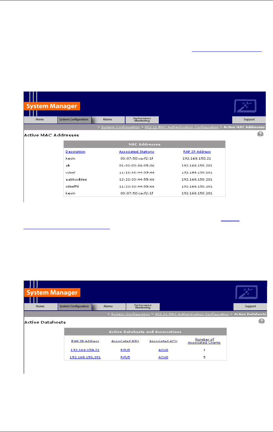
RadioFrame System
Connecting to the Customer LAN
RFN_3.1 Beta 113
6.4 Viewing WLAN User/RAP Associations
To view clients and their associated RAP(s), select the Active MAC addresses
link on the 802.11 Global Configuration page. For each RAP, the Active MAC
Addresses page lists each user associated with the RAP, including the user
name (Description) and the IP address of the workstation or piece of equipment.
Information is sorted by the RAP IP address.
To view the number of users supported by each RAP, select the Active
DataHosts and Associations link at the top of the 802.11 Global Configuration
page. The Active DataHosts page identifies the location of each RAP by RFU
and ACU, and displays the number of users associated to the RAP. You can
view the configuration for each RAP, RFU or ACU by selecting the link for that
component. This information can be used to analyze the load distribution in the
WLAN RadioFrame system.

Method of Procedure
Connecting to the Customer LAN
114 RFN_3.1 Beta
6.5 Verifying the Wireless LAN (802.11b) Installation
Verifying the LAN installation requires a laptop that has 802.11b internally or a
client card that plugs into the PCMCIA port.
1 Associate with a RAP in the RFS by matching the SSID on the client (laptop)
and the SSID that is configured in the System Manager.
2 Setup a static address on the client to communicate with the RFS (refer to the
appendixes for a list of default IP addresses for the RFS).
3 Once associated, open a command window and ping the RLIC IP addresses
to confirm that the client is properly associated with the RAP (this also
confirms connectivity up to the RLIC).
4 Once associated, navigate to a few Internet addresses. This requires that the
Administrator correctly configure their network for this navigation.

RadioFrame System
Operations and Maintenance
RFN_3.1 Beta 115
7 Operations and Maintenance
A report of the RFS iDEN/802.11 site should be maintained and left on site. The
report should include iDEN Interface, Power Plant, and RFS. This report will
provide metrics for possible concerns with individual components and /or the
entire system.
It is important that the technician performing the checks understand the
equipment theory and operation. Review the documentation (references) prior to
verification and performing service.
This chapter contains procedures for the following:
• Upgrading System Software
• Preventive maintenance
• Corrective maintenance
• Field replaceable units (FRUs)
• Alarm resolution procedures,
• Repair and technical support
7.1 Upgrading System Software
The RadioFrame System is shipped with the latest software and hardware
installed. With each new software release, RFN provides its customers with the
new software (this software can also be downloaded from the RFN FTP site) and
upgrade instructions for that release in the Customer Release Notes RFN_X.X
(P/N 991-xxxx-00). The instructions describe how to upgrade to the latest
software from any prior version.
To upgrade hardware, refer to section 7.4 Field Replaceable Units—RadioFrame
System.
7.2 Preventive Maintenance
7.2.1 iSC-3
Refer to the Gen 3 Site Controller System Manual, Motorola, 68P80801E30-O for
preventive maintenance information.
7.2.2 Power Plant
A report of the Total Plant Condition should be maintained and left on site. The
report should include rectifier, controller operation and condition of batteries. This

Method of Procedure
Operations and Maintenance
116 RFN_3.1 Beta
report will provide metrics for possible concerns with individual cells and /or the
entire battery string. This service is available from PECO II. Call 1-(419)-768-
7700 for more details.
It is important that the technician performing the checks understand the
equipment theory and operation. Review the documentation (references) prior to
verification and performing service.
• PECO II Rectifier System Manual: 127NHL-IBWS
• PECO II System Manual 40-719010-1005
• Battery Manufacturers Installation and Maintenance Documentation
The 127NHL-IBWS plant should have the following semi-annual and annual
maintenance procedures performed. Also verify all plant settings after adding or
replacing rectifiers and/or batteries.
NOTE: A software kit with interface cable is available from PECO II to aid in
troubleshooting and maintenance, via interface port to laptop. Contact PECO II
for ordering information.
7.2.2.1 Semi-Annual Maintenance
Visually inspect Rectifiers for loose or foreign items and for heat spots.
Verify proper Plant Voltages at Rectifiers, Batteries and Plant Controller.
7.2.2.2 Annual Maintenance
General
Visually inspect Rectifiers for loose or foreign items and for heat spots.
Verify proper Plant Voltages at Rectifiers, Batteries and Plant Controller.
Power Plant
Verify Alarms settings as follows:
• Fuse Alarms (FA)
• Battery Disconnect set point
• Rectifier Fail Alarm (RFA)
• Power Minor Alarm (PMN)
• Power Major Alarm (PMJ)
Check all set points and adjust if necessary. The factory settings are as follows:

RadioFrame System
Operations and Maintenance
RFN_3.1 Beta 117
• Float Voltage: 54.45 VDC
• Equalize Voltage: 55.0 VDC
• Low Voltage Alarm: 51.0 VDC ± .5VDC
• High Voltage Alarm: 56.0 VDC ± .5VDC
• Low Low Voltage Alarm: 46.0 VDC ± .5VDC
• Low Voltage Disconnect for A & B Loads: 42.0 VDC ± .5VDC
• Low Voltage Reconnect for A & B Loads: 52.0 VDC ± .5VDC (not adjustable)
If deviations from the factory settings are desired, refer to Section 1.18
“Navigating the Simple Controller” in the PECO II Rectifier System Manual:
127NHL-IBWS manual.
To verify system connections, refer to Chapters 2 & 3 for mechanical and
electrical installation information in the PECO II Rectifier System Manual:
127NHL-IBWS manual.
Verify alarms if extended to an Alarm Termination Panel.
Check operation and calibration of Plant Volt and Amp Meter.
It is important that the rectifier fans be inspected regularly to make sure they
aren't damaged or filled with dust. Be sure the plant is getting adequate
ventilation by ensuring there are no restrictions in the surrounding area such as
boxes leaning against any of the plant components, or within 18 inches of them.
Inspect all cable connections, and tighten if necessary. System connections for
AC input, battery, and distribution are plug-in, and should be checked to ensure
they are properly seated.
Ground studs/bolts should have the following torque:
Bolt Size (inches) Bolt Steel (Grade 5)
FT LBS / IN LBS
¼ 7.6 / 91.2
5/16 15.3 / 183.6
3/8 27.0 / 324.0
7/16 43.0 / 516.0
½ 64.0 / 768.0
Rectifiers
Verify Rectifier voltage and amperage setting: High Voltage (HV), Current Limit,
Low Current, Float as applicable.
Verify Alarms are extended to Plant Controller.

Method of Procedure
Operations and Maintenance
118 RFN_3.1 Beta
Thermography (optional)
A thermal scan should be done on all AC components associated with the DC
power system.
Perform thermal scans on all battery and DC power connections, DC buss-work,
and circuit breakers.
7.2.3 Batteries
Conduct the following annual maintenance:
• Inspect Batteries: All cable connections and inter-cell connections. Check for
oxidation at terminal posts and clean as required.
• Check for leaks or seepage at terminal posts and battery jar seals.
• Replace the battery jar if any leak or seepage.
• Torque battery terminal and strap connections nuts and bolts to
manufacturer’s specifications. Power Battery CSL-12100 Specification is 115
in/lbs.
• Verify battery voltage and mid-point voltage.
• Perform Midtronics battery analysis using digital battery analyzer (optional).
7.2.4 RadioFrame System
Conduct the following semi-annual maintenance:
• Visually inspect all RFS components for loose or foreign items and for visible
damage.
• Confirm that each component is receiving power (refer to the troubleshooting
tables listed in 7.3 Corrective Maintenance, next in this chapter).
• Verify that all RFS components are operational (refer to section 5.3.1.2
Checking the Status of RFS Components).
• Verify coverage validation by conducting spot tests described in section 5.4
Coverage Validation.
• Verify iDEN functionality by conducting spot tests using the procedures
described in section 5.6 RFS Functionality Test.
7.3 Corrective Maintenance
The fault indications identified in this section provide a guide for isolating failures
to a Field Replaceable Unit (FRU). The service technician should perform
troubleshooting whenever a failure occurs during normal operation that cannot be
resolved by the Operations and Maintenance Center (OMC).

RadioFrame System
Operations and Maintenance
RFN_3.1 Beta 119
Some indications list several possible failures along with corresponding
corrective actions. If a failure is isolated to the FRU level, the suspected
component should be replaced with a new one. This restores the system to
normal operation as quickly as possible. For more information, refer to section
7.6 Repair and Technical Support.
7.3.1 iSC-3
This section lists troubleshooting procedures for both the iSC-3 (site controller)
and the Environmental Alarm System (EAS). For further information, refer to the
Gen 3 Site Controller System Manual, Motorola, 68P80801E30-O.
Site Controller Troubleshooting
Indication Possible failure Corrective action
status gps MMI command
response: Satellite tracking
mode on all channels is less
than 8
Antenna, cables, surge
arrestors, RFI
Check antenna, cables, and
surge arrestors before
placing the site controller.
If antenna installation is OK,
suspect intermodulation
desensitizing.
status gps MMI command
response: S/N numbers of
mode 8 satellites are less than
25
Antenna, cables, surge
arrestors, RFI
Check antenna, cables, and
surge arrestors before
placing the site controller.
If antenna installation is OK,
suspect intermodulation
desensitizing.
ping gps MMI command
indicates no satellites tracked.
Open or damaged GPS and
surge satellites tracked.
Verify GPS antenna, lead-in,
and surge arrestor.
Slow handovers. Open or damaged GPS and
surge satellites tracked.
Verify GPS antenna, lead-in,
and surge arrestor.
Check for open 5 MHz cable
and missing termination of 5
MHz cable.
Power LED is not lit No power to site controller Check power source
Cabling
Check power cabling to site
controller. If necessary,
replace cabling.
Site controller failure Replace the site controller.
Site controller can’t
communicate over Ethernet
Ethernet cabling or
terminations
Check cabling. Verify that
each end of the cable has a
50-ohm termination.
Site controller failure Replace the site controller.
LOS/OOF LED is lit
(Loss of Signal/Loss of Frame)
T1/E1 cabling Check cabling to site
controller. If necessary,
replace the cabling.
Site controller failure Replace the site controller.
Yellow Alarm LED is lit Site controller is receiving an
alarm from the far end.
Check for proper operation
of external site equipment.

Method of Procedure
Operations and Maintenance
120 RFN_3.1 Beta
Indication Possible failure Corrective action
alarm from the far end. Notify far end.
AIS LED is lit
(Alarm Indication Signal)
Far end equipment failure NOTE: The AIS LED is lit
when the All Ones Keep
Alive signal is received.
Check for proper operation
of external site equipment.
Notify far end.
FE/CRC LED is lit
(Framing Error/CRC Error)
T1 is no configured for ESF Configure T1 correctly.
Bit errors
Check T1/E1 cabling.
Check T1/E1 levels.
Check for T1/E1 noise or
crosstalk.
Site controller failure Replace Site controller.
BPV/PD LED is lit T1 is not configured for
B8Zs
Configure T1 correctly
Bit errors
Check T1/E1 cabling.
Check T1/E1 levels.
Check for T1/E1 noise or
crosstalk.
Site controller failure Replace iSC-3.
Net LED is lit
(Network Loopback)
The Site controller has
received an in-band or out-
of-band loopback code, and
is in loopback mode.
Notify far end.
Local LED is lit
(Local Loopback)
Front panel switch has put
the iSC-3 into loopback
mode.
Push and hold the Sel/Loop
switch for 2 seconds. This
action takes the unit out of
loopback mode.
EAS Troubleshooting
Indication Possible failure Corrective action
EAS breaker on Cabinet
breaker is on, but POWER
LED (green) on EAS is not lit.
No power connected to
EAS.
Check power source.
Cabling
Check power cabling to EAS;
replace cable if necessary.
Wrong EAS response. Miswired modular cable Check EAS modular cabling.
AC fail alarm AC input, or an open or
disconnected alarm lead.
Verify AC in put, check for
open and disconnected
alarm leads.
High temperature alarm AC input to air conditioner Verify AC input.
Site air conditioner Call for service on air
conditioner.

RadioFrame System
Operations and Maintenance
RFN_3.1 Beta 121
Indication Possible failure Corrective action
Alarm sensor improperly set
or wires shorted.
Check and adjust alarm
sensor.
Alarm sensor located in a
hot spot.
Check and adjust alarm
sensor.
Low temperature alarm Air conditioner does not shut
off.
Repair HVAC.
Thermostat is set too low. Set thermostat to 78ºF
Cold air blowing on alarm
sensor.
Shield or relocate sensor.
7.3.2 Power Plant
If for any reason assistance is needed on any Power equipment, Field Service
technicians are available through Gallon, OH to assist you. Call (419)-468-7700
or (419)-468-7600 and ask for Field Service.
Troubleshooting
Indication Corrective Action
Rectifier Fail Alarm
Review alarm status on controller.
Review all alarms to ensure only an RFA and a PMN
condition exists.
Confirm error condition.
Is there an AC fail alarm?
If an AC fail condition exists, troubleshoot AC source.
If no other error conditions are present that would cause the
RFA alarm, remove and reseat the rectifier.
Does the alarm condition continue to be present?
If alarm condition is present, remove rectifier and replace
with a known good rectifier.
Error condition should clear.
If condition clears, send the faulty rectifier to PECO II
following the instructions given on page 6 of the 127NHL
manual.
If the error condition did not clear, check the pins on the
backplane and the rectifier jack.
Do all appear to be okay?
If okay, contact PECO II service following the instructions
on page 6 of 127NHL manual.
Fuse Alarm
Determine if FA originates from the six breakers on the
shelf or from an external FA that is being detected by the
system. (During installation, an external FA can be
connected to the rear of the plant to monitor for an FA
condition).
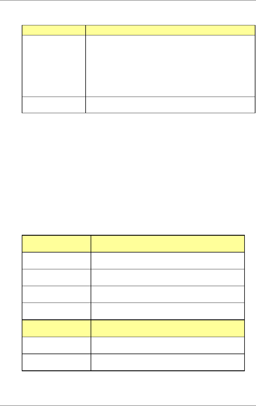
Method of Procedure
Operations and Maintenance
122 RFN_3.1 Beta
Indication Corrective Action
Reset the breaker and measure the load through the
breaker using a current measuring device.
Does the current exceed 80% of the rating of the breaker?
If yes, remove and replace the breaker with a breaker that
meets the 80% rule.
Note: Maximum rating of the shelf is 30 amps and per CB
position is 30 amps.
Do not exceed the CB/plant ratings.
If current does not exceed 80% rating and breaker does not
trip, troubleshooting is complete.
7.3.3 RadioFrame System
RadioFrame Networks equipment and components are not field repairable. Do
not attempt to repair RFN equipment and components in the field. RFN
components are individually tested prior to shipment. Should a failure occur
replacement boards must be inserted and the RFS re-booted.
This section describes troubleshooting information for each component of the
RadioFrame System: NCU, ACU, RFU, and URU. If the provided solutions do
not resolve the problem, refer to the Field Guide to the RadioFrame System for
further troubleshooting information. If none of the provided solutions resolve the
problem, contact the Customer Assistance Center (TAC) at (425) 424-7620.
7.3.3.1 Network Chassis Unit
NCU front ports Description
Port 1 (RJ45) iSC—iDEN installations only
Port 2 (RJ45) Ethernet LAN—network installations only
Ports 3-8 (RJ45) additional Ethernet LANs
EIA-232 9-pin serial port for debugging—Customer Service use only
NCU back ports
Ports 1-8 (RJ45) ACUs—up to 8 ACUs may be connected to the NCU
5MHz/1PPs IN BNC connector for timing interface

RadioFrame System
Operations and Maintenance
RFN_3.1 Beta 123
NCU back ports
5MHz/1PPs OUT BNC connector for timing interface
GPS ANT GPS antenna connection
Each card installed in the front and back of the NCU has two LEDs: Power (top)
indicates power, and Status (lower) indicates the status of the card. Each RJ45
port has two LEDs: Link (right) indicates Ethernet connectivity, and Activity (left)
blinks to indicate Ethernet activity. All LEDs should light as green. For all other
conditions, refer to the following table.
Indication Possible failure Corrective action
Power and Status LEDs
for cards installed in
front or back of NCU are
not lit
no power to NCU Verify that the power cord is
installed and properly seated.
Verify that the power source is
operational (120VAC or
–48VDC).
Contact Customer Support.
Status LED is red—top
front card only
timing source not
available
Connect the timing source. In
iDEN installations, this is usually
the iSC-3. In some cases, the
timing source is the GPS
antenna.
Check all connections.
failed initialization
Reboot the system: unplug the
NCU, and plug it in again. Boot
up may take several minutes.
fan is not working Verify that the fan is operational.
If the fan is not working, unplug
the NCU and contact Customer
Support.
Status LED is red—any
card
card is not operational Remove and reseat card.
Contact Customer Support.
RJ45 port Link and
Activity LEDs are not lit,
or the Activity LED is not
blinking
connection is not being
made between RFS
components
For the affected port, verify that
all cabling between components
is properly connected.
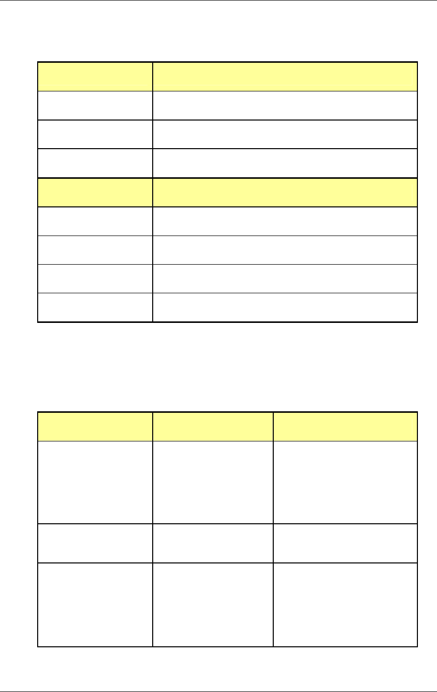
Method of Procedure
Operations and Maintenance
124 RFN_3.1 Beta
7.3.3.2 Airlink Chassis Unit
ACU front ports Description
RJ45 Port 1 NCU—connects the ACU to the NCU
RJ45 Ports 2-8 not currently used
EIA-232 9-pin serial port for debugging—Customer Service use only
ACU back ports
Ports 1-8 (RJ45) RFUs—up to 8 RFUs may be connected to the ACU
5MHz/1PPs IN not currently used
5MHz/1PPs OUT not currently used
GPS ANT not currently used
Each card installed in the front and back of the ACU has two LEDs: Power (top)
indicates power, and Status (lower) indicates the status of the card. Each RJ45
port has two LEDs: Link (right) indicates Ethernet connectivity, and Activity (left)
blinks to indicate Ethernet activity. All LEDs should light as green. For all other
conditions, refer to the following table.
Indication Possible failure Corrective action
Power or Status LEDs
for cards installed in
front or back of ACU are
not lit
no power to ACU Verify that the power cord is
installed and properly seated.
Verify that the power source is
operational (120VAC or
–48VDC).
Contact Customer Support.
Status LED is red—any
card
card is not operational Remove and reseat card.
Contact Customer Support.
failed initialization
Reboot the system: unplug the
ACU, and plug it in again. Boot
up may take several minutes.
fan is not working Verify that the fan is
operational.
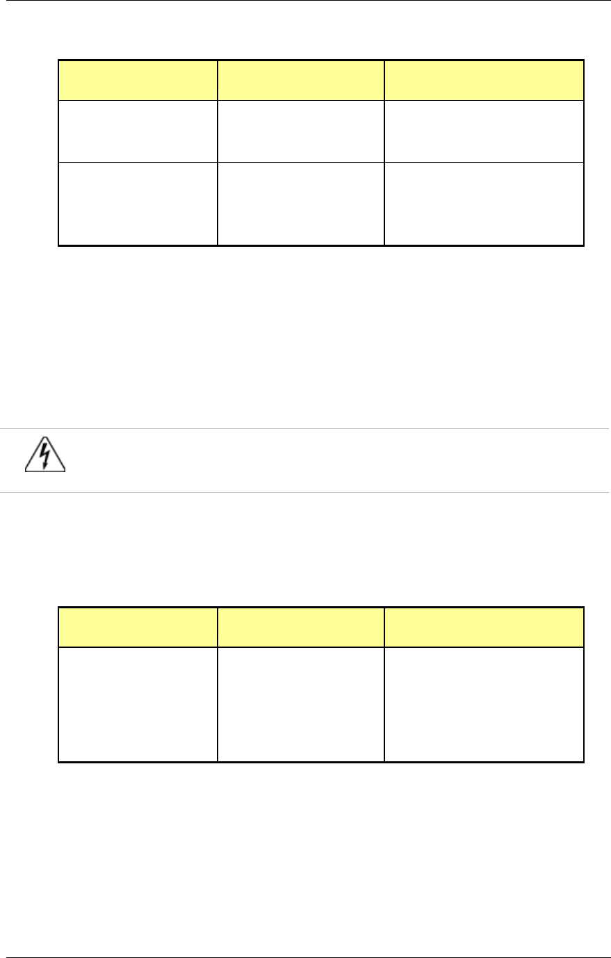
RadioFrame System
Operations and Maintenance
RFN_3.1 Beta 125
Indication Possible failure Corrective action
If the fan is not working, unplug
the ACU and contact Customer
Support.
RJ45 port Link and
Activity LEDs are not lit,
or the Activity LED is not
blinking
connection is not being
made between RFS
components
For the affected port, verify that
all cabling between
components is properly
connected.
7.3.3.3 RadioFrame Unit
The RadioFrame Unit (RFU) has two RJ45 ports on the top of the back cover of
the unit: MAIN and AUX. Only the MAIN port is used. The AUX port has a
protective cover that must not be removed. During installation, ensure that the
RFU is receiving power and connectivity from the ACU before inserting
RadioBlades into the RFU or placing the front cover on the RFU.
Warning!
Do not remove the protective cover from or insert a connector into the AUX port. This will
cause damage to the RFU, the ACU, or both.
The MAIN port has two LEDs: Link (right) indicates Ethernet connectivity, and
Activity (left) blinks to indicate Ethernet activity between the RFU and the ACU.
For all other conditions, refer to the following table.
Indication Possible failure Corrective action
MAIN Port LEDs do not
light
connection is not being
made between the RFU
and the ACU
Verify that all cabling between
the ACU and the RFU is
properly connected.
Verify that the ACU is powered
on.
Contact Customer Support.
7.3.3.4 Universal Repeater Unit
The Universal Repeater Unit (URU) has two pairs of RJ45 ports on the front of
the unit. Each pair (IN/OUT) indicates Ethernet connectivity and activity between

Method of Procedure
Operations and Maintenance
126 RFN_3.1 Beta
two RFS components. During installation, ensure that the URU is receiving
power before installing RFS components.
Each RJ45 port has two LEDs: Link (right) indicates Ethernet connectivity, and
Activity (left) blinks to indicate Ethernet activity between RFS components. For all
other conditions, refer to the following table.
Indication Possible failure Corrective action
LEDs are not lit connection is not being
made between URU
and RFS components
Verify that the URU is plugged in to an
approved power source.
Verify that each RFS component is
powered on.
Verify that all cabling between the RFS
components is properly connected.
7.4 Field Replaceable Units
7.4.1 iSC-3
For the iSC-3 and EAS, refer to Chapter 11 “FRU Replacement Procedures” of
the Gen 3 Site Controller System Manual, Motorola, 68P80801E30-O.
7.4.2 Power Plant
7.4.2.1 Removal and Replacement of Distribution CBs
1 Loosen the three screws that secure the top access cover, and then remove
the cover.
2 Grasp the Circuit Breaker to be replaced and pull it out until it is removed
from the assembly.
3 Install the new CB, pressing it in until it is firmly seated.
Note: Be very careful when installing the output breakers. The common pin of
the alarm circuit on the breaker must engage the jack on the plant. Tolerance
is tight; go straight in with the breaker.
4 Ensure there is not a Fuse Alarm condition present. If an FA is present,
remove and install the CB until the FA condition clears.

RadioFrame System
Operations and Maintenance
RFN_3.1 Beta 127
7.4.2.2 Rectifier Removal and Replacement
1 Loosen the retaining screw and gently pull on the rectifier handle until the
rectifier is removed from the cage.
2 Install the new rectifier into position, and gently push on the front until it is
seated.
3 Secure the rectifier module to the cage with the retaining screw.
7.4.3 RadioFrame System
In the case of chassis units, replacement boards must be inserted and the RFS
re-booted.
1 Always use a static grounding wrist strap before handling any board—do not
attach the wrist strap to any painted surface on the chassis unit.
Note
It is not necessary to unplug the NCU or the ACU prior to removing or
inserting a board.
2 Facing the chassis unit, remove the card that is to be replaced, or the blank
faceplate, following these guidelines:
∙ Loosen the blue knurled knobs on both sides of the board.
∙ Pull firmly to unseat the board from the connectors inside the chassis unit.
∙ Gently slide the board straight out and away from the chassis unit so as
not to damage any components contained on the board.
3 Remove the new board from its antistatic packaging and insert it into the
chassis unit as shown in the following illustration, and follow these guidelines:
∙ Do not jam the board in any way while inserting it.
∙ Do not mount the board in any orientation other than that specified in the
diagram.
∙ Insert the board straight into the chassis unit so as not to damage any
components contained on the board.
∙ Press firmly to seat the board into the connectors within the chassis unit.
∙ Tighten the blue knurled knobs on each end of the board finger tight
only—do not use a screwdriver to tighten the screws and do not over
tighten.
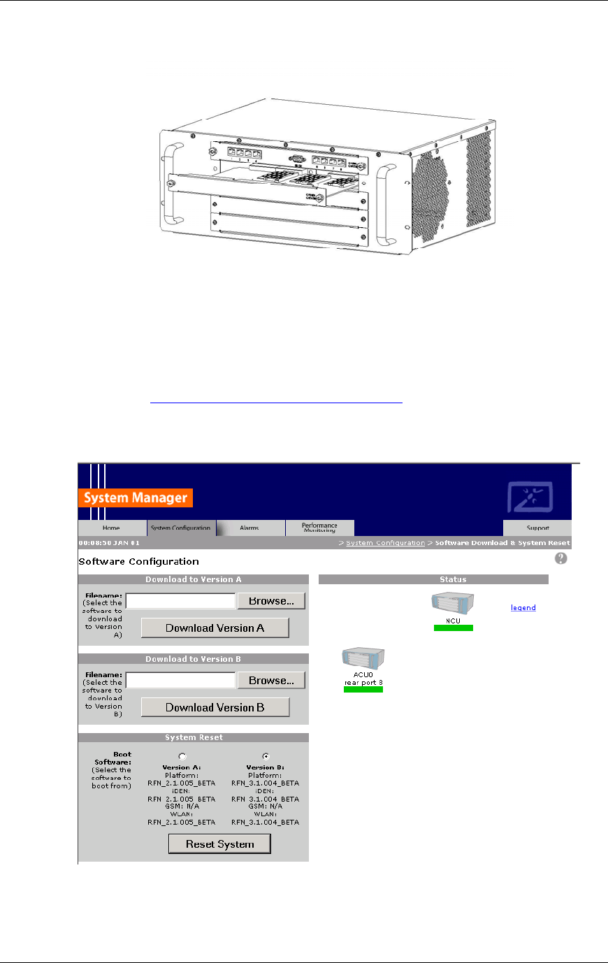
Method of Procedure
Operations and Maintenance
128 RFN_3.1 Beta
Figure 34 Replacing a board in an NCU or an ACU.
4 Place the old board in the antistatic packaging for shipment.
5 Restart the RadioFrame System.
Select the Software Download & System Reset link located at the bottom of
the NCU configuration page, and select the “Reset System” button to cause a
system reset. The reboot may take several minutes to complete.

RadioFrame System
Operations and Maintenance
RFN_3.1 Beta 129
7.5 Alarm Resolution Procedures
The RFS provides fault alarming and isolation within System Manager for
individual components, which consists of detecting catastrophic faults that
prevent an RFS component from responding to a periodic “ping”. Depending on
the severity, alarms are sent to the OMC via the iSC-3. All alarms passed to the
OMC use an Alarm Code, such as 39005, which uses the event description
“Unable to key BR”.
This section describes:
• How to view alarms in System Manger,
• OMC alarm code and severity levels, and
• System Manager alarms and resolution procedures.
7.5.1 Viewing System Manager Alarms
System Manager displays system-related errors. Only some of these errors are
sent to the OMC.
1 To view alarms and other system-related errors in System Manager, select
the Alarms tab.
The Alarms Log displays RFS alarms, listed by Time of occurrence
(including the date), in a sequence of 200 alarms at a time—No. (see the
following illustration). Approximately 25 alarms are visible at any one time. At
the bottom of the page, you can see which alarms are currently displayed, in
this case, 99 through 118 of 118 alarms.
NOTE: If the Alarms page is empty, System Manager is still loading the
page.
2 To display alarms that have scrolled out of view, select first, prev, next, last
or all at the bottom of the alarm page, then enter a value in the Show text
box and press enter.
For example, to view the first 20 alarms, click first and type 20 in the text box,
then press Enter. To return to the bottom of the list of alarms, select last and
type a value in the text box.
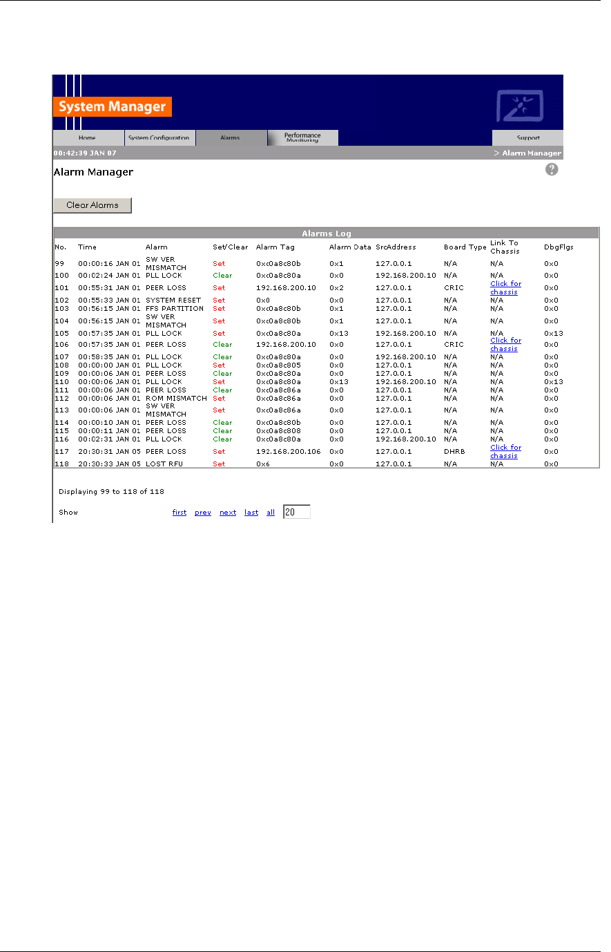
Method of Procedure
Operations and Maintenance
130 RFN_3.1 Beta
Figure 35 Alarms are listed up to 200 at time and continue to scroll as events
occur.
For each Alarm, System Manager displays the alarm description and whether
the alarm is new (Set) or has been cleared (Clear). The same alarm will continue
to be listed as a set alarm until it has been cleared. If an alarm is not cleared, it
will be sent to the OMC (see “System Manager Alarm Descriptions” later in this
section). Other alarms might occur before an alarm clears, so the ‘set’ and ‘clear’
for the same alarm do not necessarily appear in sequence.
The Alarm Tag uniquely identifies each alarm using either the actual IP address
or hex digits to represent the IP address of the affected component. In the latter
case, the last four digits of the alarm tag represent the last two sets of digits of
the IP address of the component. For example, 0xc0a80679 represents
xxx.xxx.06.121. The IP address of the board generating the alarm is shown
under SrcAddress, or ‘source address’.
Board Type identifies which board within a chassis unit is affected (APC, CRIC,
etc.). For these alarms, select Click for chassis link to display the page for that
component.

RadioFrame System
Operations and Maintenance
RFN_3.1 Beta 131
NOTE: When troubleshooting alarms that require assistance from RadioFrame
Networks, you’ll need to provide the data displayed in the Alarm Data and
DbgFlgs fields.
7.5.2 OMC Alarm Code and Severity Levels
All RFS alarms sent to the OMC use an Alarm Code, such as 35009 (see the
following table). The Event Description for this alarm is ‘Unable to key BR’. The
severity level—minor, major or critical—indicates which RFS component has
been affected (see the second table below).
Event Description
Alarm Code 35009
Event Type CntrlBrd
Alarm Type Equipment Failure
Actionable Yes
Severity Minor, Major or Critical
Bounce Threshold (x) 3
Bounce Threshold Minutes 30
Duration Threshold 10
Related Alarms None
R & C RC
Outage Y/N S1_El CY
Event Description Unable to key BR
Advisor Site Service call
Comments None
Alert Names BREFCTLBD35009
Last updated 8/3/2001
Revision
Change Notes 8/3/2001: per new EBTS rules baseline.
Changed severity and threshold from GR1 to:
Severity=minor
BounceThreshold=3
Bounce Threshold Minutes=30
Duration Threshold=10
Action Create trouble ticket.
Contact Field Technician.
TS/BR
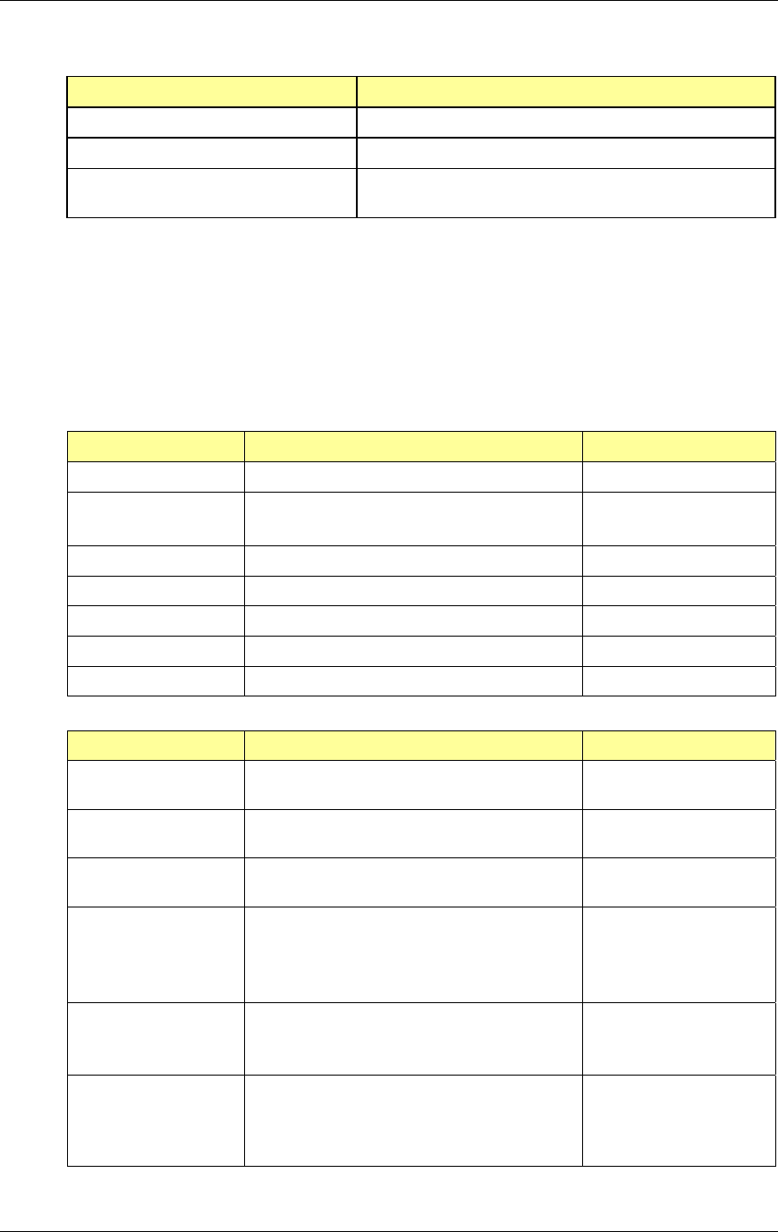
Method of Procedure
Operations and Maintenance
132 RFN_3.1 Beta
‘Unable to Key BR’ alarm severity Description
minor An iDEN RadioBlade or 802.11b RAP has failed.
major An RFU has failed.
critical A card in a chassis unit has failed (except for the RLIC,
which returns alarm information.)
7.5.3 System Manager Alarms
The first table below lists System Manager alarms that are sent to the OMC, the
OMC alarm message, and the severity of the alarm. The second table describes
all System Manager alarms, and what action is required, if any, to resolve the
problem.
OMC Alarm System Manager Alarm Severity
BOARD DISABLED PEER LOSS MINOR (RAP only)
BOARD DISABLED PEER LOSS CRITICAL
(any board except RAP)
EXCESS RESETS EXCESS RESETS CRITICAL
ENABLE WAIT BR ENABLE FAIL MINOR
NO SPAM IN APC APC NO SPAM CRITICAL
RADIO BLADE LOST IDENRB LOSS MINOR
RFU DISABLED LOST RFU MAJOR
Alarm Description Action
5MHz CLOCK RIC or RLIC temporarily lost the 1 PPS
reference.
No action required.
ALARMS CLEARED Alarm Manager was cleared using the Clear
Alarms button.
No action required.
APC NO SPAM There are more BRs than the current SPAM
resources can support.
Add more SPAMs as
required.
APC SLOT MISS Slot mismatch detected on APC or NPC.
Causes a slot sync procedure three times.
If the slot still is not found, generates the
alarm APC SYNC FAIL.
APC SYNC FAIL APC SLOT MISMATCH is not able to
recover after three attempts.
Causes a system reset.
ASSGN FAILURE More than three consecutive assignment
failures occurred on a BR without any
successful calls in between.
The BR is locked out.

RadioFrame System
Operations and Maintenance
RFN_3.1 Beta 133
Alarm Description Action
BAD RB SLOT RB reported a slot number that is out of
range (1-8).
Replace either the RFU
or the RB.
BAD VGA 1180s received from the RB have a
consistently high Gain setting, even in the
absence of any signal indicating Rx
Calibration issues.
RIC will attempt to reset the RB three times,
and then generates a Calibration alarm.
BR ACTIVITY Not currently used. No action required.
BR ENABLE FAIL BR remained disabled for more than 30
minutes.
Causes the BR to go into permanent Error
mode and will not participate in further fault
recovery procedures.
BR STARTUP FAIL Not currently used. No action required.
CHNL SETUP ERR iSC channel setup (channelSetup) is invalid
or inconsistent.
Causes the BR to be de-keyed and to return
to LEI mode to restart the channel
allocations with the iSC.
COMMANDED
RESET
System Reset was initiated via System
Manager.
Causes a system reset.
COVERAGE HOLE One BR in a sector has fewer RBs than
other BRs in that sector.
The BR that is short of Radio Blades has
locked.
DHRB RESET A problem in the DHRB has caused it to
reset.
No action required.
DHRB TASK EXCEP Task Exceptions has occurred for some task
on the DHRB.
DHRB resets.
No action required.
DSP 1180 FLOOD The RB 1180 DSP address is flooding all
ports.
Sends a Stop Tx command to the RB and
causes a system reset.
DSP HPI ERROR Problem in accessing HPI interface for a
DSP.
If errors go beyond a threshold, SPAM is
reset.
DSP LOAD ERROR DSP software not found.
DSP was not initialized.
Check the ffs files etc.

Method of Procedure
Operations and Maintenance
134 RFN_3.1 Beta
Alarm Description Action
DSP LOST PDU DSP is not sending any PDUs to the APC.
The CPU received fewer than threshold
PDUs within a fixed period from the DSP.
SPAM is reset.
DSP TX IQ FAIL DSP Tx counter is not incrementing as per
expectations, implying that DSP has
stopped transmitting.
SPAM is reset.
DSP TX NULL PDU DSP is transmitting too many NULL packets
because it didn’t receive PDUs from CPU.
SPAM is reset.
EXC DSP RESET DSP SPAM has been reset more than four
times within the last 20 minutes.
Causes a system reset.
EXCESS RESETS More than four resets have occurred within
30 minutes.
BRs permanently lock up and require a
system reset.
Reset system.
EXT BR RESET BR received a reset command from the iSC.
Event logged to indicate that BRs went
down on iSC request.
FAN1 ALARM Chassis FAN1 is malfunctioning. Check the chassis fans
for proper operation.
FAN2 ALARM Chassis FAN2 is malfunctioning. Check the chassis fans
for proper operation.
FFS PARTITION Board booted from wrong partition.
May indicate problem with the files on boot
partition.
Verify software versions
for each partition in
System Manager.
IDENRB LOSS Communication with the iDEN Radio Blade
has been lost.
The corresponding BR is locked and all
associated RBs have stopped.
LAPD LINK FAIL The LAPD connection between the BR and
the iSC has been lost.
The BR will try to re-establish the LAPD and
sends a state change trap to iSC.
Check the iSC
connection.
LOST RB DSP is not getting 1180 packets from the
RB.
APC logs the alarm and sends a message to
the RIC to reset the RB.
LOST RFU All the iDEN RBs and Datahosts in an RFU
have been lost.
Check the RFU
connections, etc.
MISC EVT/ALM

RadioFrame System
Operations and Maintenance
RFN_3.1 Beta 135
Alarm Description Action
NET POOL ERROR The free Mblock cluster has gone below 40
on an NPC or AP, the threshold for
APC_NETPOOL_LOWMARK or
NPC_NETPOOL_LOWMARK.
Causes a system reset.
OVERTEMP A chassis has overheated. Check the chassis for
proper operation.
PEER LOSS Communication with a board has been lost.
RIC has detected a PEER LOSS from the
RLIC.
Causes a system reset, unless the cause is
a DHRB, which self resets.
PLL LOCK A RIC or RLIC PLL went out of lock.
The RLIC locks and de-key all BRs, and
then sends a state change trap to the iSC.
RB ALARMS-CRC An RB has generated a RIC CRC error
within the last 30 minutes.
Monitor the RB/RFU
and if it keeps
incrementing, replace
the RB/RFU.
RB ALARMS-MISC An RB has generated a RIC error other than
the CRC error.
If this alarm occurs
frequently while the
system is running,
monitor the RIC.
RB CALIBRATION The RB did not reset after three attempts
due to a Bad VGA.
Identify the RB and
replace it.
RB E2 READ ERR RBSession EEPROM read attempts have
failed beyond threshold.
The RB goes into an error state.
Replace something.
RB ERROR STATE The RB has gone into an error state
because there was either an error reading
I/Q DAC values, or the values were invalid.
Identify and replace the
RB.
RB SLOT MISS APC has detected an RB in the wrong slot.
APC sends a message to the RIC with the
RBIndex.
Causes slot synchronization for the RB.
RB SYNC FAIL Three consecutive attempts to sync up the
RB failed.
Reset the SPAM.
RB TX GAIN CAL
ROM MISMATCH Board boot version is not the same as the
RLIC.
SPAM FAILED Lost DSP PDUs have exceeded threshold.
SPAM is reset.
SW VER MISMATCH Board software version is not the same as
the RLIC.
SYSTEM RESET Alarms that result in a system reset cause
thi l t f th RLIC

Method of Procedure
Operations and Maintenance
136 RFN_3.1 Beta
Alarm Description Action
this alarm, except for the RLIC.
All BRs and boards are locked and reset
except the RLIC.
TASK STARVATION A task is using all the CPU time and starving
other tasks.
Prints a list of ready task and causes a
system reset (unless it’s a DHRB, which
resets itself).
TASK SUSPEND A task got suspended on a board.
Board is reset (unless source is RLIC).
UNK 1180 FAIL The message UNK 1180 FLOOD failed to
recover after three attempts.
Causes a system reset.
UNK 1180 FLOOD RB registration caused wrong address for
DSP 1180 packets.
RB is reset to cause registration.
If fails after three attempts, causes alarm
UNK 1180 FAIL.
UNKN ISC MSG Unknown iSC message has been received. Let the developers
know.
7.6 Repair and Technical Support
RadioFrame Networks provides technical support services to RFN customers for
the installation and maintenance of RadioFrame Networks equipment. For iSC-3
or T1 related questions, please contact the RFN customer.
7.6.1 Before calling...
Have the following information available prior to contacting RadioFrame
Networks Technical Assistance Center (TAC) to minimize downtime:
• location of the RadioFrame System
• date the RadioFrame System was put into service
• System Manager software version
• symptoms of the problem
• if an alarm was generated, the alarm information including the information
from the Alarm Data and DebugFlag fields on the Alarms page in System
Manager
• date the problem was first noticed
• if the problem can be reproduced

RadioFrame System
Operations and Maintenance
RFN_3.1 Beta 137
• what causes the problem to occur
• any unusual circumstances contributing to the problem (i.e., dropped calls)
7.6.2 Technical Assistance Center
For support of RadioFrame Networks equipment, contact the RadioFrame
Networks Technical Assistance Center at:
(US) (800) 762-6322
7.6.3 Repair Procedure
If RFN equipment should require service or repair, note the following information,
then contact the RFN Technical Assistance Center at (800) 762-6322:
• Include the warranty and serial numbers of the affected equipment.
• Give a clear return address, including a contact person, phone number and,
preferably, an alternate contact person and phone number.
• Always use a static grounding wrist strap before handling any board or
RadioBlade.
• Securely package the board in the original shipping carton, if available.
Otherwise, package in a static protection bag in a well padded carton.

Method of Procedure
Appendix A: Glossary
138 RFN_3.1 Beta
Appendix A Glossary
Acronym Term Description
10Base2
10Base2 is also known as Thin Ethernet. 10Base2 cables
support transmission speeds up to 10 Mbits/second. The
maximum distance per segment is 185 meters.
10BaseT
10BaseT is the most common form of Ethernet cabling. The
cable is thinner and more flexible than the coaxial cable used
for the 10Base2 standard. 10BaseT is also known as
unshielded twisted-pair (UTP). 10BaseT cables support
speeds up to 10 Mbps. The maximum distance per segment is
500 meters.
ACU Airlink Chassis Unit The central baseband processing unit for the RFS. Rx/Tx
airlink traffic to/from RFUs.
APC Airlink Processing Card Interface to the RIC for the control of RFU components and the
transfer of voice I/Q samples to/from RFUs.
CSU Channel Service Unit The CSU provides the T-1 connection between the iSC-3 and
the telephone company that provides the T-1 line.
EIA Electronic Industries
Alliance
The EIA organization establishes electronic interface
standards.
EAS Environmental Alarm
System
The EAS provides a central location for site alarm signal
processing. The EAS monitors environmental conditions of the
site, including power, smoke alarms, and intrusion alarms.
ERTM Ethernet Rear Transition
Module Located in the NCU, provides clock and data to the ACU.
ESD Electrostatic Discharge
The dissipation of electricity, commonly known as a shock.
ESD can destroy semiconductor products, even when the
discharge is too small to be felt.
ethernet media
converter
Hardware box that converts the 10base2 (coaxial television)
cable to a 10baseT (RJ45) cable. In the RadioFrame System,
this hardware connects the 10base2 cable coming from the
iSC-3 to Port 1 of the NCU.
FRU Field Replaceable Unit
Any unit (module, board, or card) that can be “hot-swapped”,
that is, replaced with another unit while the power is connected
to the item housing the unit.
GPS Global Positioning
System
A system that uses geostationary satellites to triangulate the
position of a GPS receiver located on earth.
ground strap
A metal strip placed between the antennas of RadioBlade that
are installed in an RFU. It prevents RF attenuation within the
RFU.
iDEN integrated Digital
Enhanced Network
Motorola’s proprietary digital technology that combines the
capabilities of a standard analog dispatch system with that of a
cellular interconnect system. iDEN uses an advanced
proprietary modulation technology consisting of a speech
compression scheme enabling three or six communication
paths over a single 25 kHz RF channel.
iSC-3 integrated Site
Controller
The controller and communications gateway between the RFS
and the RFN customer central network. The iSC-3 is required
for all RadioFrame Networks iDEN installations.

RadioFrame System
Appendix A: Glossary
RFN_3.1 Beta 139
Acronym Term Description
NCU Network Chassis Unit
The central network processing unit for the RFS. Also central
management entity for managing configuration and User
Information.
NPC Network Processing
Cards
Interface to the RLIC for the bi-directional transfer of voice I
and Q samples to/from RFUs.
PDU Power Distribution Unit The panel used for distributing power to the units within the
main rack.
PERTM Powered Ethernet Rear
Transition Module
Located in the ACU, provides power, clock, and data to the
RFUs.
RB RadioBlade Provides the airlink interface for the iDEN standard.
RFN RadioFrame Networks Equipment designer and manufacturer of RFS equipment.
RFS RadioFrame System
Digital Communication System for indoor wireless device
users. The RFS consists of several components: NCU, ACU,
RFUs and iDEN RadioBlades.
RFU RadioFrame Unit RF front end for each of the implemented air interface to the
User equipment and connects to ACU on the other end.
RFU BP RadioFrame Unit - Back
Plane
Facilitates High speed intermodule communication between
RFU components and between RFU and ACU.
RIC RadioFrame Interface
Card
Provide the Ethernet switch fabric to route packets to/from
ACUs, RFUs and external IP networks. Also will host a micro-P
(MPC-8240) as primary controller to APCs.
RLIC RadioFrame LAN
Interface Card
Provide the Ethernet switch fabric to route packets to/from
ACUs. Also hosts a micro-P serving as primary controller of
NPCs.
RSSI Received Signal
Strength Indication Strength of the received call signal, in dBm.
SELV Safety Extra-Low
Voltage
A secondary electrical circuit designed so that under normal
and signal fault conditions, its voltages do not exceed a safe-
value.
SPAM Signal Processing Array
Module
A connectorized card which plugs into an APC or NPC and
provides the digital signal processing resources.
SQE Signal Quality Estimate An estimate of signal quality, based on the received signal
strength and quality.
T1 Digital Transmission
Rate 1
A North American leased-line connection capable of carrying
1.544 megabits of data per second (Mbps). T-1 lines are
commonly used to connect networks, ISPs and others to the
Internet.
T1/E1
An E-1 line is the European equivalent to the North American
T-1. However, an E-1 line carries information at the rate of
2.048 Mbps instead of the 1.544 Mbps of a T-1.
T568B
Wiring standard for RadioFrame System CAT-5 cables.
Denotes a specific order of the CAT 5 wires leading into the
RJ-45 connector.
URU Universal Repeater Unit
Repeats signal and timing and can also provide power to an
RFU. Extends distance between RFS components from 100
meters to 300 meters.

Method of Procedure
Appendix A: Glossary
140 RFN_3.1 Beta
Appendix B Site Survey
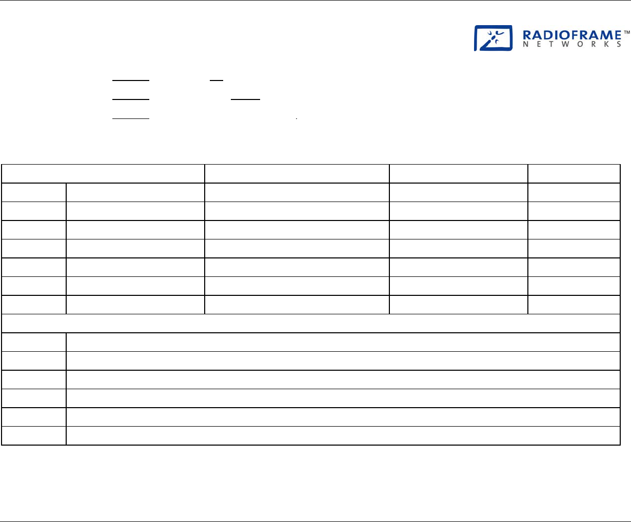
RadioFrame System
Appendix B: Site Survey
RFN_3.1 Beta 141
Site Survey REV A
Carrier Date
Customer Project #
Site Location RFN Project Engineer
Present for Site Survey Name Email Phone
Carrier representative
Customer representative
Building/Site Manager
Installation vendor
RFN Engineer
RFN Project Manager
Other
Customer Expectations
Who will provide RF measurements?
Who will install the RFS?
Who will commission the installation?
Will the RFS be shipped directly to the site or staged?
Will the RFS be assembled and tested at the customer site?
Digital photos permitted during the site survey?
© Copyright 2001 RadioFrame Networks, Inc. All rights reserved.

Method of Procedure
Appendix B: Site Survey
142 RFN_3.1 Beta
Customer Expectations (continued)
Troubleshooting expectations?
Other
RF Planning
Which and how many channels will be provided for indoor use?
Coverage requirements (see RF Measurements below)
Vertical coverage required?
Site WLAN
What is the internet connectivity?
WLAN configuration?
Mobile IP?
Static/administration of IP?
24 X 7 point of contact
RFS Equipment Requirements
Cable path from iSC
Wall mount or ceiling mount of RFUs preferred?
iSC Equipment
iSC location
Power requirements
Rack size
© Copyright 2001 RadioFrame Networks, Inc. All rights reserved.
RadioFrame System
Appendix B: Site Survey
RFN_3.1 Beta 143
RFS Equipment Requirements (continued)
iSC Equipment (continued)
T1 connection location
GPS antenna requirement (cable path to outside antenna location)
NCU
NCU location
Power requirements
4U 19” rack space available per NCU?
Cable run distance from iSC
ACU
ACU location
Power requirements
4U 19” rack space available per ACU?
Cable run distance from NCU
RFU
Wall mount?
Above ceiling panels available? If so, which floors?
Power Requirements
120VAC or –48VDC available?
UPS required?
© Copyright 2001 RadioFrame Networks, Inc. All rights reserved.
Method of Procedure
Appendix B: Site Survey
144 RFN_3.1 Beta
Installation Requirements
Cable and Path Requirements
Plenum rated cable required?
Innerduct required?
Conduit required?
Existing vertical access between floors?
Space available for additional new cable in existing stubs and/or conduit?
Core drill required?
Dedicated CAT 5 (or higher) available?
Ceiling Type
Open
Suspended
Acoustical tile
Hard plaster
Metal
Other
Ceiling Height
Standard
Other
© Copyright 2001 RadioFrame Networks, Inc. All rights reserved.

RadioFrame System
Appendix B: Site Survey
RFN_3.1 Beta 145
Installation Requirements (continued)
Wall Type
Standard drywall construction
Cement/brick
Metal
Other
Firewall
Load bearing
Other RF Barriers
Identify RF blocking areas, items and locations
Local Issues
Union(s) required (identify)?
Local code requirements?
Building management standards?
Permits required?
Other
Access
When can work be conducted (regular hours, after hours, weekends)?
Special scheduling requirements
Point of contact
© Copyright 2001 RadioFrame Networks, Inc. All rights reserved.
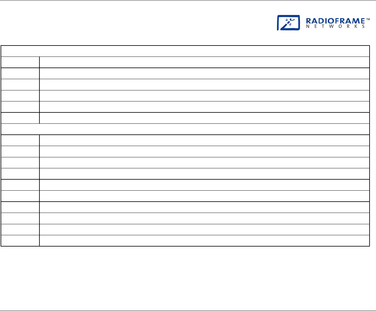
Method of Procedure
Appendix B: Site Survey
146 RFN_3.1 Beta
Installation Requirements (continued)
Access (continued)
Escort required
Between Buildings Only
Space available to mount hubs in 19” racks (fiber solution only)?
New rack space location identified?
Identify all Telecom closets for remote fiber units
Other Requirements/Comments
© Copyright 2001 RadioFrame Networks, Inc. All rights reserved.

RadioFrame System
Appendixes
RFN_3.1 Beta 147
Appendix C NCU and ACU Main Rack Installation
The RadioFrame System NCU and one ACU are mounted in the main rack prior
to shipment to the site. Complete the following three procedures to install the
NCU and main rack ACU:
• Mount the NCU in the Main Rack
• Mount the ACU in the Main Rack
• Connect the NCU to the ACUs
Mount the NCU in the Main Rack
The NCU is the main controller of the RadioFrame System. The NCU is mounted
in the main rack supplied with –48VDC power.
1 Find these items in the NCU shipping container: one NCU, four mounting
screws, one coaxial cable with two male BNC connectors for connecting to
the iSC, and one set of product documentation.
2 Mount the NCU only in an EIA-standard compliant (19”) rack using all 4
screws provided. Refer to the site documentation for the exact location of the
NCU. For safe operation, follow these guidelines:
• Do not mount the NCU in any orientation other than that specified in the
following illustration.
• Mount the NCU so that both the front and the back are accessible.
• If the mounting holes do not line up, adjust the NCU up or down until the
mounting holes line up.
•
Caution
Do not block the air vents on the sides or rear of the NCU.
3 Plug the NCU into main rack power source (rectifier or PDU).
4 Verify that the NCU is receiving power and that each NCU card is
operational.
Each card installed in the front and back of the NCU has two LEDs: Power
and Status. All LEDs should light green.
Note
The Status LED on the top card in the front of the NCU will remain red until the
NCU is connected to a timing source.
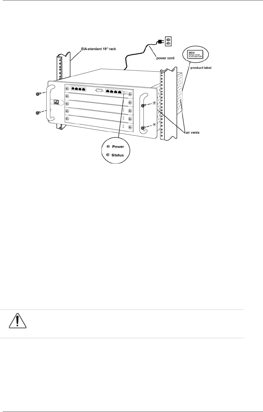
Method of Procedure
Appendixes
148 RFN_3.1 Beta
Figure 36 Mount the NCU only in an EIA-standard compliant 19” rack.
Mount the ACU in the Main Rack
The ACU is mounted in the main rack supplied with –48VDC power.
1 Find these items in the ACU shipping container: one ACU and four mounting
screws.
2 Mount the ACU only in an EIA-standard compliant (19”) rack using all 4
screws provided. For safe operation, follow these guidelines:
• Do not mount the ACU in any orientation other than that specified in the
following illustration.
• Mount the ACU so that both the front and the back are accessible.
• If the mounting holes do not line up, adjust the ACU up or down until the
mounting holes line up.
Caution
Do not block the air vents on the sides or rear of the ACU.
3 Plug the ACU into main rack power source (rectifier or PDU).
4 Verify that the ACU is receiving power and that each NCU card is operational.
Each card installed in the front and back of the ACU has two LEDs: Power
and Status. All LEDs should light green.
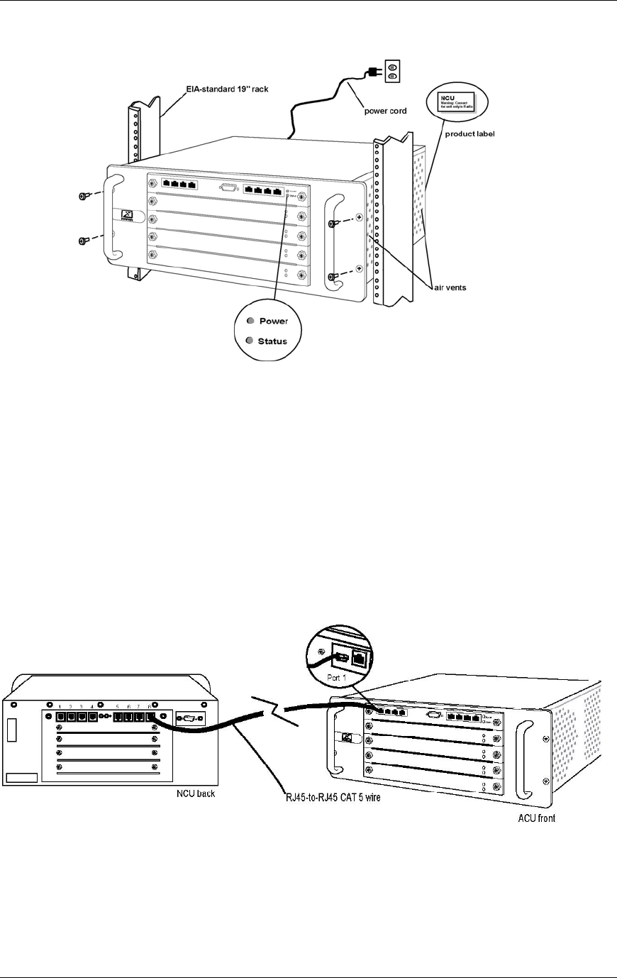
RadioFrame System
Appendixes
RFN_3.1 Beta 149
Figure 37 Mount the ACU only in an EIA-standard compliant 19” rack.
Connect the NCU to the ACUs
After the main rack has been installed and all wiring for the RFS has been
completed, connect the main rack ACU and all remote ACUs to the NCU.
1 Connect the RJ45-to-RJ45 CAT 5 cable for each ACU to the specified RJ45
port (1-8) on the back of the NCU.
Refer to the site documentation to determine which ACU connects to each
port on the NCU. The Activity and Link LEDs above the ports will remain unlit
until each ACU has been installed and plugged in.
Figure 38 Connect the RJ45-to-RJ45 CAT 5 cable for each ACU to the specified
RJ45 port on the back of the NCU.

Method of Procedure
Appendixes
150 RFN_3.1 Beta
Appendix D RFS Default IP Addresses
All chassis boards, RFU backplanes, and RAPs are issued a default IP address
during initial setup (iDEN RadioBlades do not require IP addresses). The
following table lists default IP addresses for all chassis unit boards, as well as the
default IP address required for logging in to the RadioFrame System. In addition:
• RFU backplane default IP addresses are 192.168.200.90 through
192.168.200.153
• RAP default IP addresses are 192.168.200.154 through 192.168.200.254
Device Card Type Chassis Slot IP Address
Laptop N/A N/A 192.168.200. 4
NCU RLIC Slot 0 192.168.200. 5
NPC Slot 1 192.168.200. 6
NPC Slot 2 192.168.200. 7
NPC Slot 3 192.168.200. 8
ACU-1 RIC Slot 0 192.168.200. 10
APC Slot 1 192.168.200. 11
APC Slot 2 192.168.200. 12
APC Slot 3 192.168.200. 13
ACU-2 RIC Slot 0 192.168.200. 20
APC Slot 1 192.168.200. 21
APC Slot 2 192.168.200. 22
APC Slot 3 192.168.200. 23
ACU-3 RIC Slot 0 192.168.200. 30
APC Slot 1 192.168.200. 31
APC Slot 2 192.168.200. 32
APC Slot 3 192.168.200. 33
ACU-4 RIC Slot 0 192.168.200. 40
APC Slot 1 192.168.200. 41
APC Slot 2 192.168.200. 42

RadioFrame System
Appendixes
RFN_3.1 Beta 151
Device Card Type Chassis Slot IP Address
APC Slot 3 192.168.200. 43
ACU-5 RIC Slot 0 192.168.200. 50
APC Slot 1 192.168.200. 51
APC Slot 2 192.168.200. 52
APC Slot 3 192.168.200. 53
ACU-6 RIC Slot 0 192.168.200. 60
APC Slot 1 192.168.200. 61
APC Slot 2 192.168.200. 62
APC Slot 3 192.168.200. 63
ACU-7 RIC Slot 0 192.168.200. 70
APC Slot 1 192.168.200. 71
APC Slot 2 192.168.200. 72
APC Slot 3 192.168.200. 73
ACU-8 RIC Slot 0 192.168.200. 80
APC Slot 1 192.168.200. 81
APC Slot 2 192.168.200. 82
APC Slot 3 192.168.200. 83
RFU-1 Backplane N/A 192.168.200. 90
RFU-2 Backplane N/A 192.168.200. 91
RFU-3 Backplane N/A 192.168.200. 92
.
.
153
RAP-1 N/A N/A 192.168.200 154
RAP-2 N/A N/A 192.168.200 155
RAP-3 N/A N/A 192.168.200 156
.
.
254

Method of Procedure
Appendixes
152 RFN_3.1 Beta
Appendix E RF Planning Guide 990-1001-00
Appendix F System Manager Guide 981-6300-00
Appendix G RFN Recommended Data Fill
998-0100-10
Appendix H RFN Field Guide 998-1000-00