RadioFrame Networks MCRB10 MCRB User Manual 998 4001 00
RadioFrame Networks, Inc MCRB 998 4001 00
Users Manual

RadioFrame Networks
MC-Series System
Installation & Testing
April 19, 2005
998-4001-00 Rev C
Deleted: February 11

MC-Series System Installation & Testing
ii RadioFrame Networks, Inc.
Service Information
This equipment complies with part 15 of the FCC Rules. Operation is subject to the two following conditions: This
device may not cause harmful interference, and this device must accept any interference received, including
interference that may cause undesired operation. This equipment has been tested and found to comply with the limits
pursuant to part 90.691 of the FCC Rules. These limits are designed to provide reasonable protection against harmful
interference when the equipment is operated in a commercial environment.
Notices
These installation standards have been prepared to provide Nextel Communications with general standards
necessary to ensure that installed RadioFrame Networks equipment operates in accordance with the design
parameters in the owned or leased buildings of Nextel Communications and its customers, and to make certain
equipment is installed safely and efficiently.
RadioFrame Networks reserves the right to revise this document for any reason, including, but not limited to,
conformity with standards promulgated by various governmental or regulatory agencies, utilization of advances in the
state of the technical arts, or to reflect changes in the design of equipment, techniques, or procedures described or
referred to herein.
Liability to anyone arising out of use or reliance upon any information set forth herein is expressly disclaimed, and no
representation or warranties, expressed or implied, are made with respect to the accuracy or utility of any information
set forth herein.
Copyrights and Trademarks
RadioFrame Networks, RadioBlade, and the RadioFrame Networks logo are trademarks or service marks, and
RadioFrame is a registered trademark of RadioFrame Networks, Inc. You may not use these or any other
RadioFrame Networks trademarks or service marks without the written permission of RadioFrame Networks, Inc. All
other trademarks and trade names are the property of their respective owners.
Throughout this publication, the terms RadioFrame Networks, RadioFrame and RFN signify RadioFrame Networks,
Inc., and Nextel signifies Nextel Communications.
MC-Series System Installation & Testing
© Copyright 2005 RadioFrame Networks, Inc. All Rights Reserved.

MC-Series System Installation & Testing
RadioFrame Networks, Inc. iii
Contents
1 Introduction........................................................................................................................... 1
1.1 Record of Revisions....................................................................................................... 1
1.2 References .................................................................................................................... 1
1.3 General Safety Information............................................................................................ 2
1.4 Repair and Technical Support ....................................................................................... 3
2 System Description ..............................................................................................................6
2.1 MC-Series System Configuration................................................................................... 7
2.2 RadioFrame Networks Hardware................................................................................... 9
2.3 System Manager Software........................................................................................... 24
2.4 Non-RFN Hardware ..................................................................................................... 25
2.5 Specifications............................................................................................................... 27
3 Pre-Installation.................................................................................................................... 33
3.1 Site Planning ............................................................................................................... 33
3.2 Scheduling / Logistics .................................................................................................. 36
3.3 MC-Series System Installation Kit................................................................................ 36
3.4 iDEN Configuration ...................................................................................................... 37
4 Installation .......................................................................................................................... 38
4.1 Site Inspection ............................................................................................................. 38
4.2 Receipt of Equipment .................................................................................................. 38
4.3 Mounting the MC-Series System Cabinet .................................................................... 39
4.4 Mounting Non-RFN Equipment in the MC-Series System Cabinet .............................. 39
4.5 Mounting Auxiliary Equipment ..................................................................................... 43
4.6 Cabinet-to-Site Cabling................................................................................................ 43
4.7 Intra-cabinet Cabling.................................................................................................... 46
5 Final Checkout and Commissioning ................................................................................. 47
5.1 Prerequisites................................................................................................................ 47
5.2 Checkout Procedures .................................................................................................. 48
5.3 Initial Powering Procedure........................................................................................... 48
5.4 System Setup .............................................................................................................. 50
5.5 Connect the MC-Series System to the Third-party RF Distribution System.................. 55
5.6 Functionality Test......................................................................................................... 55
6 Datafill Parameters & Optimization Procedures............................................................... 57
6.1 Unsupported Datafill Parameters................................................................................. 57
6.2 Parameters that Do Not Apply to the MC-Series System............................................. 58
6.3 Recommended Datafill Parameters ............................................................................. 58
6.4 MIB Disparity ............................................................................................................... 61
6.5 Local Performance Monitoring ..................................................................................... 62

MC-Series System Installation & Testing
iv RadioFrame Networks, Inc.
7 Scheduled and Unscheduled Maintenance....................................................................... 64
7.1 Annual Maintenance .................................................................................................... 64
7.2 Troubleshooting Guidelines ......................................................................................... 64
7.3 Fault Indications........................................................................................................... 64
7.4 System Manager Alarms.............................................................................................. 68
7.5 RF Shelf Alarms and Test Ports................................................................................... 87
7.6 RadioBlade Alarm Handling......................................................................................... 89
7.7 Serial Log Upload Procedure....................................................................................... 91
7.8 Power Down Procedure............................................................................................... 92
7.9 Field Replaceable Unit (FRU) Procedures................................................................... 93
7.10 TOR Tx Measurement Procedure.............................................................................. 112
8 System Configuration Changes....................................................................................... 113
8.1 Upgrading MC-Series System Software..................................................................... 113
8.2 Adding or Removing RadioBlades ............................................................................. 118
8.3 Adding a Sector ......................................................................................................... 118
8.4 Removing a Sector .................................................................................................... 120
8.5 Parts and Suppliers ................................................................................................... 122
8.6 Available Field Replaceable Units (FRUs) ................................................................. 123
8.7 Spares ....................................................................................................................... 124
A. Glossary ........................................................................................................................ 125
B. Default IP Addresses ........................................................................................................ 127
C. Cabling Diagrams: 3-Sector Configuration..................................................................... 128
D. Cabling Diagrams: Omni Configuration.......................................................................... 134
E. Tx / Rx Curves................................................................................................................... 140
F. Functionality Test Procedures......................................................................................... 142
G. System Manager ............................................................................................................... 148
H. BER Test Procedure ......................................................................................................... 156

MC-Series System Installation & Testing
RadioFrame Networks, Inc. v
Figures
Figure 1 The MC-Series System cabinet ................................................................................... 6
Figure 2 MC-Series System 3-sector configuration ................................................................... 8
Figure 3 MC-Series System functional diagram......................................................................... 9
Figure 4 BIC front view............................................................................................................. 10
Figure 5 BIC rear view.............................................................................................................. 10
Figure 6 BIC CRIC ports and indicators................................................................................... 10
Figure 7 BPC indicators............................................................................................................ 11
Figure 8 ERTM ports and indicators......................................................................................... 11
Figure 9 CRTC ports and indicators......................................................................................... 11
Figure 10 AIC front view............................................................................................................. 13
Figure 11 AIC rear view.............................................................................................................. 13
Figure 12 AIC CRIC ports and indicators................................................................................... 14
Figure 13 BPC+SPAM indicators ............................................................................................... 14
Figure 14 ERTM ports and indicators......................................................................................... 14
Figure 15 RBS group functional diagram ................................................................................... 16
Figure 16 RBS interior, top down view....................................................................................... 17
Figure 17 RBS front view............................................................................................................ 17
Figure 18 RBS rear view ............................................................................................................ 18
Figure 19 iDEN 2-port RadioBlade transceiver .......................................................................... 19
Figure 20 RF Shelf functional diagram....................................................................................... 20
Figure 21 RF Shelf front view..................................................................................................... 21
Figure 22 RF Shelf rear view...................................................................................................... 21
Figure 23 PDU front view ........................................................................................................... 23
Figure 24 PDU rear view ............................................................................................................ 23
Figure 25 Punch block location within the MC-Series rack........................................................ 26
Figure 26 MC-Series System rack locations for non-RFN hardware ......................................... 40
Figure 27 Top of the rack (TOR) cabling and equipment........................................................... 44
Figure 28 RadioBlade fault Bounce and Duration for alarm generation.................................... 90
Figure 29 RF Shelf front view..................................................................................................... 94
Figure 30 RF Shelf rear view...................................................................................................... 94
Figure 31 Front view of BIC........................................................................................................ 98
Figure 32 Front view of AIC........................................................................................................ 99
Figure 33 Front view of RBS .................................................................................................... 101
Figure 34 Replacing the CRIC in the BIC or AIC. .................................................................... 103
Figure 35 Replacing the BPC in the BIC or the BPC+SPAM in the AIC. ................................. 104
Figure 36 Rear of BIC (ERTM and CRTC) and AIC (ERTM only). .......................................... 106
Figure 37 Front view of the RadioBlade Shelf (RBS)............................................................... 108

MC-Series System Installation & Testing
vi RadioFrame Networks, Inc.
Figure 38 PDU Rear view.........................................................................................................111
Figure 39 PDU rear view .......................................................................................................... 111
Figure 42 MC-Series System Omni Configuration ................................................................... 134
Figure 43 Transmit filter frequency response........................................................................... 140
Figure 44 Receive filter frequency response............................................................................ 141
Tables
Table 1 MC-Series System FRUs ............................................................................................. 4
Table 2 PDU Circuit Breaker Overview................................................................................... 23
Table 3 TOR output power is based on the DefaultTxPower and the Attenuator setting ....... 59
Table 4 Alarm Interface Port Pinout........................................................................................ 87
Table 5 RF Shelf Diagnostic Port Pinout................................................................................. 88
Table 6 MC-Series System FRUs ........................................................................................... 93
Table 7 MC-Series System FRUs ......................................................................................... 123
Table 8 Interconnect Call Quality, Setup and Stability.......................................................... 142
Table 9 Group Dispatch Call Quality, Setup, and Stability.................................................... 142
Table 10 Private Dispatch Call Quality, Setup, and Stability .................................................. 143
Table 11 Packet Data Latency over the MC-Series System (Ping –n 100 –w 2000 xx.xxx .....144
Table 12 Packet Data Latency over Motorola EBTS .............................................................. 144
Table 13 Handover & Idle Mode Reselection ......................................................................... 145
Table 14 Interconnect Connection Stability............................................................................. 145
Table 15 Dispatch Connection Stability .................................................................................. 145
MC-Series System Installation & Testing
Introduction
RadioFrame Networks, Inc. 1
1 Introduction
This MC-Series System Installation & Testing manual provides an overview of the RadioFrame
Networks Microcell (MC-Series) System and describes standards for installing, modifying and
maintaining RadioFrame Networks equipment at Nextel and Nextel customer sites. All
specifications and requirements pertain to MC-Series System equipment required in Nextel iDEN
(integrated Digital Enhanced Network) installations. RadioFrame Networks recommends reading
the entire manual before attempting to install or operate RadioFrame Networks equipment.
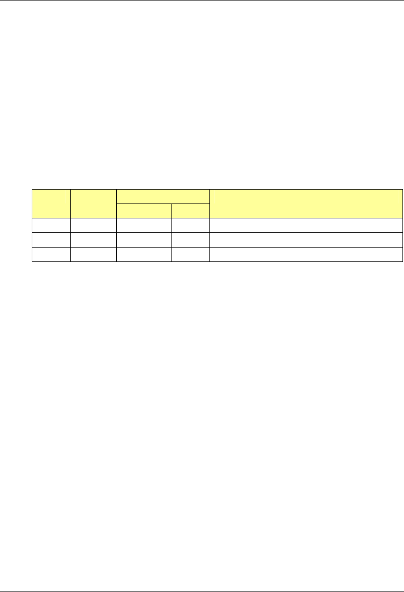
1.1 Record of Revisions
Effect on Issue Date
Page Para
Reason for Revision
A Nov 2004 All Reorganize document; add content
B Dec 2004 All Update content
C Feb 2005 All Update content
Submit comments and corrections to:
• RadioFrame Networks, Inc.
1120 112th Avenue NE, Suite 600
Bellevue, WA 98004
• Telephone (425) 278-2780
• FAX (425) 278-2781
• E-mail USinfo@radioframenetworks.com
This document is posted as a .pdf file on the RadioFrame Networks web site at:
http://www.radioframenetworks.com/support/
1.2 References
In addition to this manual, the following technical manuals are related to the MC-Series System
and may be needed for installation or maintenance.
• Generation 3 Site Controller System Manual, Motorola, 68P80801E30-O
• iDEN OMC-R Configuration Management Parameters Technical Manual, 68P80802E10
• Channel Service Unit (CSU) manufacturer’s documentation
• Cabinet manufacturer’s documentation (shipped with MC-Series System)
• Power supply and battery manufacturer's installation and maintenance documentation
• Distributed Antenna System (DAS) manufacturer's documentation
MC-Series System Installation & Testing
Introduction
2 RadioFrame Networks, Inc.
• General Dynamics R2660 Series Communications System Analyzer Operators Manual, 68-
P35270C001 Rev F
• Quality Standards—Fixed Network Equipment (FNE) Installation Manual (R56), Motorola,
R56 current edition
• National Electrical Code (NEC), current edition
• National Fire Protection Associations (NFPA) Code 70
• ASTM (American Society For Testing and Materials) 488-90
• Bellcore Technical Specifications 1089, GR-63-CORE
1.3 General Safety Information
Read all the notices in this section prior to installing or using the MC-Series System or any of its
components.
1.3.1 Static Sensitive Precautions
Electrostatic discharge (ESD) can damage equipment and impair electrical circuitry. It occurs
when electronic printed circuit cards are improperly handled and can result in complete or
intermittent failures.
• Prior to handling, shipping, and servicing equipment, always put on a conductive wrist strap
connected to a grounding device to discharge any accumulated static charges. All RFN FRUs
ship with a disposable anti-static wrist strap.
Warning!
Use extreme caution when wearing a conductive wrist strap near sources of high
voltage. The low impedance provided by the wrist strap also increases the danger
of lethal shock should accidental contact with high voltage sources occur.
• Place FRUs only on an anti-static mat when removed from the system. The conductive
surface must be connected to ground through 100kΩ.
• Do not use non-conductive material for packaging FRUs for shipment or storage. Wrap all
FRUs with anti-static (conductive) material. Replacement FRUs shipped from the factory are
packaged in a conductive material.
• If possible, retain all original packing material for future use.
1.3.2 Safety Warnings
Warning!
Never defeat the ground conductor or operate the equipment in the absence of a
suitably installed ground conductor. Contact the appropriate electrical inspection
authority or an electrician if uncertain that suitable grounding is available.
Warning!
Ultimate disposal of this product should be handled according to all national laws
and regulations.

MC-Series System Installation & Testing
Introduction
RadioFrame Networks, Inc. 3
Warning!
The user is cautioned that changes or modifications made to the equipment that
are not expressly approved by the party responsible for compliance, could void
the user’s authority to operate the equipment.
Warning!
To ensure FCC compliance of this equipment, it is the user’s responsibility to
obtain and use only shielded and grounded interface cables.
Warning!
FCC RF Exposure Compliance: FCC RF exposure compliance must be
addressed at the time of licensing, as required by the responsible FCC
Bureau(s), including antenna co-location requirements of §1.1307(b)(3). The
applicable exposure limits, to demonstrate compliance, are specified in FCC Part
1.1310. Additionally, to comply with FCC RF exposure compliance requirements,
the antenna(s) used for this transmitter must be fixed-mounted with at least 25
cm separation distance from any person. The installer of the antenna to be used
with this transmitter may be required to perform an MPE evaluation and an
Environmental Assessment (EA) of the location at the time of licensing per CFR
47 Part 1.1307. Fixed mounted antenna(s) that are co-located with other
antenna(s) must satisfy the co-location requirements of Part 1.1307 for satisfying
RF exposure compliance
1.3.3 Recommendations
• Do not work alone if potentially hazardous conditions exist.
• Never assume that power is disconnected from a circuit. Always check.
• Look carefully for possible hazards in the work area, such as moist floors, ungrounded
extension cables, frayed power cords, and missing safety grounds.
1.4 Repair and Technical Support
RadioFrame Networks provides technical support services to Nextel for the installation, operation
and maintenance of RadioFrame Networks equipment. For iSC-3 or T1 related questions, please
contact Nextel.
1.4.1 Before calling...
Have the following information available prior to contacting RadioFrame Networks Technical
Assistance Center (TAC) to minimize downtime:
• Location of the MC-Series System
• MC-Series System software version
• Symptoms of the problem
• If an alarm was generated, the alarm information from the Alarm Log in System Manager
• Date the problem was first noticed
• If the problem can be reproduced

MC-Series System Installation & Testing
Introduction
4 RadioFrame Networks, Inc.
• What causes the problem to occur
• Any unusual circumstances contributing to the problem (i.e., loss of power)
1.4.2 Technical Support
For support of RadioFrame Networks equipment, contact the RadioFrame Networks Technical
Assistance Center (TAC) at:
(US) 1-800-328-0847
1.4.3 Field Replaceable Unit (FRU) Policy
The MC-Series System has been designed so that Field Repairable Units (FRUs) can be
replaced to restore normal system operation as quickly as possible. RFN components are
individually tested prior to shipment. If RFN equipment should require service or repair, note the
following information, and then contact the RFN Technical Assistance Center at (800) 328-0847:
NOTE: Do not attempt to repair RFN equipment and components in the field.
NOTE: Always use a static grounding wrist strap before handling any chassis or RadioBlade.
• Include the serial numbers of the affected equipment.
• Give a clear return address, including:
- contact person,
- phone number, and an
- alternate contact person and phone number (if possible).
• Securely package the FRU in its original shipping carton, if available. Otherwise, package in
a static protection bag in a well-padded carton.
Refer to section 8.6 FRU Replacement Procedures for replacing any of the following equipment.
For equipment not supplied by RadioFrame Networks, follow standard Nextel policies and
procedures for FRU replacement.
Table 1 MC-Series System FRUs
P/N Description
176-0840-xx 800 MHz MC Series iDEN 2-Port RadioBlade (RB) Transceiver
176-0870-xx 800 MHz RF Shelf
176-0535-xx RadioBlade Transceiver Shelf (RBS)
176-0800-xx MC-15 Airlink Interface Chassis (AIC)
176-0900-xx MC-15 BTS Interface Chassis (BIC)
176-7570-xx Base Processing Card (BPC)
176-7550-xx Base Processing Card (BPC) with SPAM
176-7540-xx Common RadioFrame Interface Card (CRIC)

MC-Series System Installation & Testing
Introduction
RadioFrame Networks, Inc. 5
P/N Description
176-7562-xx Ethernet Rear Transition Module (ERTM)
176-7510-xx Signal Processing Array Module (SPAM)
176-0820-xx CRTC
176-7502-xx 4U Chassis
176-0600-xx PDU
176-1219-xx Fan Tray w/Fans for 4U Chassis
176-0011-xx Fan for RBS, RF Shelf, AIC & BIC
MC-Series System Installation & Testing
System Description
6 RadioFrame Networks, Inc.
2 System Description
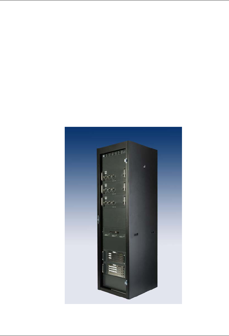
The MC-Series System is a stand-alone microcell base transceiver station (BTS) that provides
radio communication links between the land network and mobile subscriber units in an integrated
Dispatch Enhanced Network (iDEN). The MC-Series System interfaces with the Mobile Switching
Office (MSO) via a standard T1 interface. This link also provides the Operations and Maintenance
Center (OMC) with alarm information, and enables the OMC to remotely control and configure
system operations via a standard site datafill.
The MC-Series System contains both RadioFrame Networks' and non-RFN equipment enclosed
in a single 19” equipment cabinet. The MC-Series System, or MC-15, is a three-sector
configuration that supplies five full-duplex iDEN carriers per sector with the option to upgrade to
24 channels total. In the future, this platform will allow further upgrades to 36 BRs.
The MC-Series System is shipped ready to install and configure. The customer provides all non-
RFN hardware, T1 connectivity, datafill (network provisioning), antenna system, GPS (as required
by iSC), electrical supply and the necessary permitting.
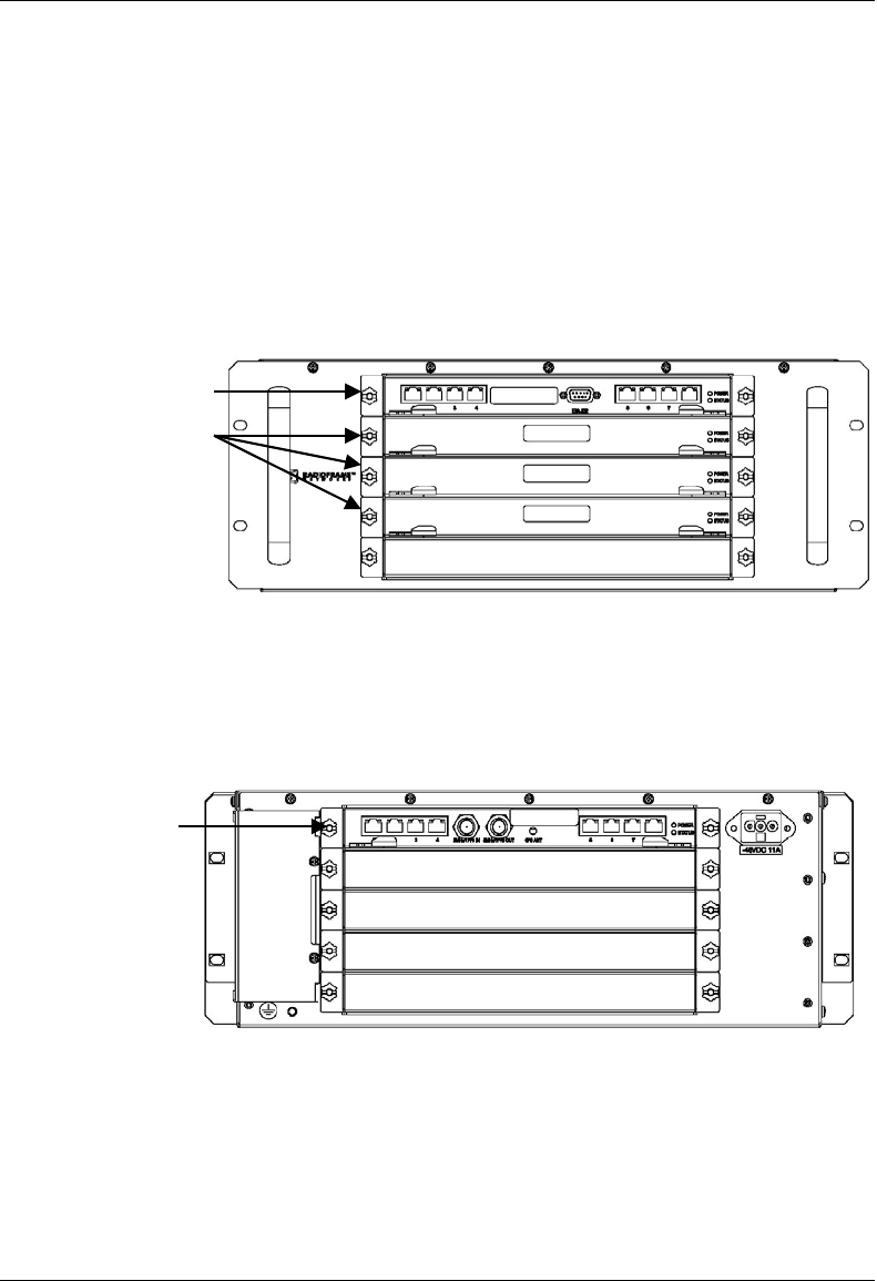
Figure 1 The MC-Series System cabinet

MC-Series System Installation & Testing
System Description
RadioFrame Networks, Inc. 7
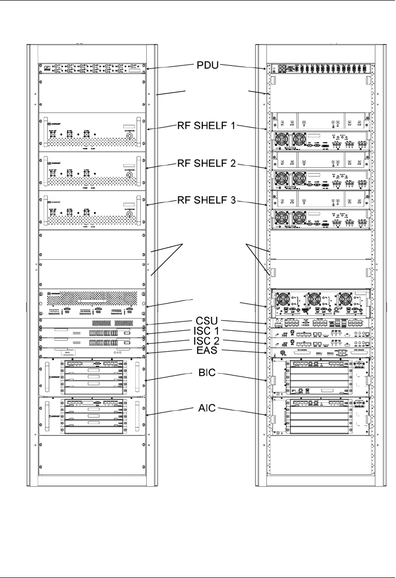
2.1 MC-Series System Configuration
The MC-Series System can be configured to have 1, 2, or 3 sectors. The single sector, or omni
configuration can have up to 20 BRs. In multi-sector configurations, the BRs must be assigned to
sectors in groups of 8. For a 3-sector system the maximum number of BRs per sector is 8. For a
2-sector configuration one of the sectors can have up to 16 BRs, while the other sector can have
up to 8, providing a maximum capacity of 24 BRs in a 2- or 3-sector configuration.
The MC-Series System includes the following RadioFrame Networks hardware:
• BTS Interface Chassis (BIC) is the interface to the iSC and routes Ethernet traffic for up to
three sectors.
• Airlink Interface Chassis (AIC) performs the digital receive and transmit function for each
RadioBlade (RB) and provides the common timing source for each RBS.
• RadioBlade Shelf (RBS) enables up to 24 RadioBlade® transceivers. A second RBS is
required to provide diversity through “receive only” RadioBlade transceivers.
• iDEN 2-port RadioBlade transceivers (RBs) insert into slots in the RBS; each RB corresponds
to one iDEN BR.
• RF Shelf provides Rx-Tx amplification, filtering, and distribution between the RBSs and
external equipment.
• Power Distribution Unit (PDU) distributes DC power and provides overcurrent protection to
each component in the MC-Series System cabinet.
The MC-Series System includes the following non-RadioFrame Networks hardware:
• ISC-3s: two integrated Site Controllers (iSC 3s) for redundancy
• Environmental Alarm System (EAS) provides additional external alarming as required.
• Channel Service Unit (CSU) single-rack unit, high multi-purpose cross-connect, with the
ability to aggregate multiple types of traffic onto a single T1 for backhaul to the MSO.
• DC power source.
MC-Series System Installation & Testing
System Description
8 RadioFrame Networks, Inc.
Figure 2 MC-Series System 3-sector configuration
future RBS
(2 & 3)
reserved for
powerplant
RBS 1
MC-Series System Installation & Testing
System Description
RadioFrame Networks, Inc. 9
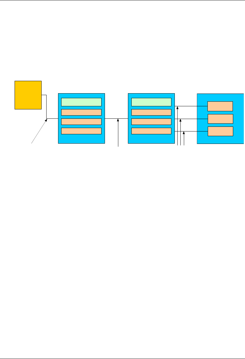
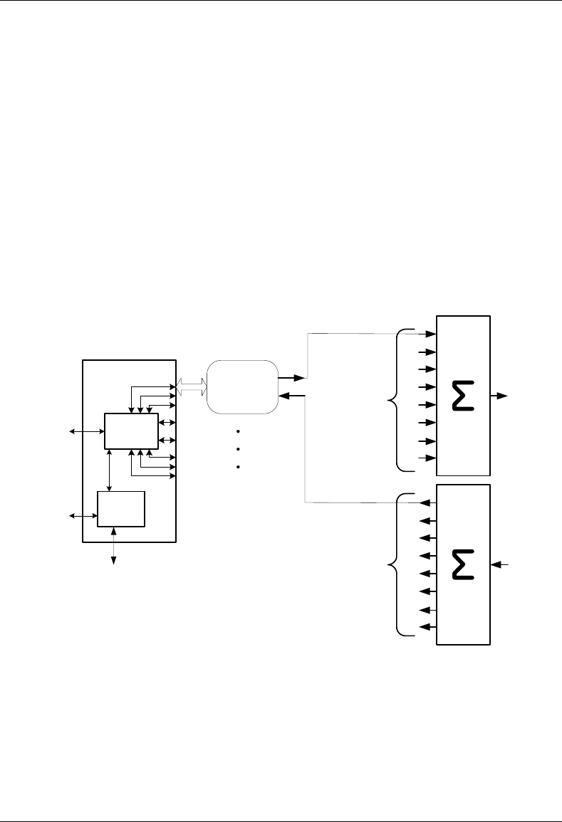
2.2 RadioFrame Networks Hardware
RadioFrame Networks hardware receives layer 3 control messages (control, voice, packet data,
SNMP, etc.) from the iSC, and converts them into layer 2 PDUs (Protocol Data Units) that are
sent every 15mSec (received every 7.5 mSec). Then the AIC converts the layer 2 PDUs into raw
layer 1 BaseBand I/Q samples that are sent/received every 7.5 mSec.
Figure 3 MC-Series System functional diagram
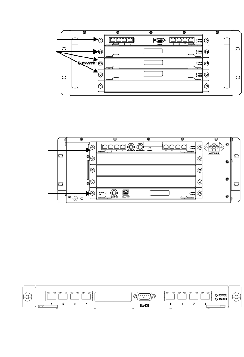
2.2.1 BTS Interface Chassis (BIC)
The BTS Interface Chassis (BIC) interfaces to the iSC and provides all Base Radio management
functionality, including timing, converts iSC layer 3 messaging to layer 2 packets, and converts
1PPS 5MHz clock to packet-delivered timing. Within the BIC chassis are four assemblies (see the
following illustrations):
• BIC Common RadioFrame Interface Card (CRIC)
• BTS Processing Card (BPC)—up to three BPCs per system, one BPC per sector, deployed in
front slots 2, 3, and 4
• Ethernet Rear Transition Module (ERTM)
• Coax-to-RJ45 Transceiver Card (CRTC)
ISC
CRIC
BPC (A)
BPC (C)
CRIC
BPC (A) + SPAM
BPC (B) + SPAM
BPC (C) + SPAM
BIC
10 Base 2
100 BaseT
100 BaseT
AIC
Layer 3 Messges Layer 2 PDUs Layer 1
BaseBand I/Q
Samples
RBS
Group A
Group C
Group B
BPC (B)
MC-Series System Installation & Testing
System Description
10 RadioFrame Networks, Inc.
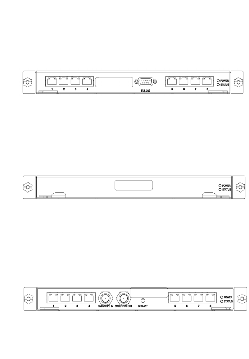
Figure 4 BIC front view
Figure 5 BIC rear view
2.2.1.1 BIC CRIC
The BIC Common RadioFrame Interface Card (CRIC) is located in the top front slot of the BIC.
The BIC CRIC provides the Ethernet switch fabric to route packets to/from the AIC and hosts a
microprocessor that serves as the primary controller of BPCs for system management purposes.
The BIC CRIC has a serial port for local serial access, and eight 10/100BaseT Ethernet ports.
Currently, ports 1 through 7 are not used; only port 8 is used for local Ethernet access.
Figure 6 BIC CRIC ports and indicators
ERTM
CRTC
BPC
BIC CRIC
MC-Series System Installation & Testing
System Description
RadioFrame Networks, Inc. 11
2.2.1.2 BPC
Three BTS Processing Cards (BPCs) are located in BIC front slot positions 2, 3, and 4. The BPC
hosts a microprocessor to perform iDEN voice management and is responsible for layer 2 call
processing.
Figure 7 BPC indicators
2.2.1.3 ERTM
The Ethernet Rear Transition Module (ERTM) is located in the top rear slot of the BIC. The ERTM
interfaces to the CRIC via eight RMII ports in the chassis midplane. The ERTM provides Ethernet
connectivity between the BIC and AIC as well as a connection to the CRTC.
Figure 8 ERTM ports and indicators
2.2.1.4 CRTC
The Coax-to-RJ45 Transceiver Card (CRTC) is located in the bottom rear slot of the BIC. The
CRTC provides conversion of the 10-base 2 connection at the iSC to a 10-base T connection in
the BIC.
Figure 9 CRTC ports and indicators
MC-Series System Installation & Testing
System Description
12 RadioFrame Networks, Inc.
2.2.1.5 BIC Ports
Card Port Description
BIC CRIC Ports 1-7 (RJ45) not currently used
Port 8 (R-45) Nextel technician local Ethernet access
EIA-232 9-pin serial port Nextel technician local serial access
BPC N/A N/A
ERTM Port 1 (RJ45) CRTC Port 10BaseT
Ports 2-7 (RJ45) AIC ERTM port 4
Port 8 (RJ45) Remote Ethernet connectivity (DNX-1u Ethernet)
5MHz/1PPS IN iSC-3 5MHz/1PPS port
5MHz/1PPs OUT not currently used (no terminator required)
GPS ANT not currently used
CRTC 10Base2 – iSC ISC-3 10Base2 port
10BaseT – iSC BIC ERTM port 1
2.2.1.6 BIC Indicators
Each card installed in the BIC has a Power and a Status LED. In addition, each RJ45 port has
an Ethernet link LED that indicates connectivity and an Ethernet activity LED that indicates
Ethernet traffic.
LED Indication
Power Indicates power is applied to card
Status Indicates timing synchronization
link activit
y
MC-Series System Installation & Testing
System Description
RadioFrame Networks, Inc. 13
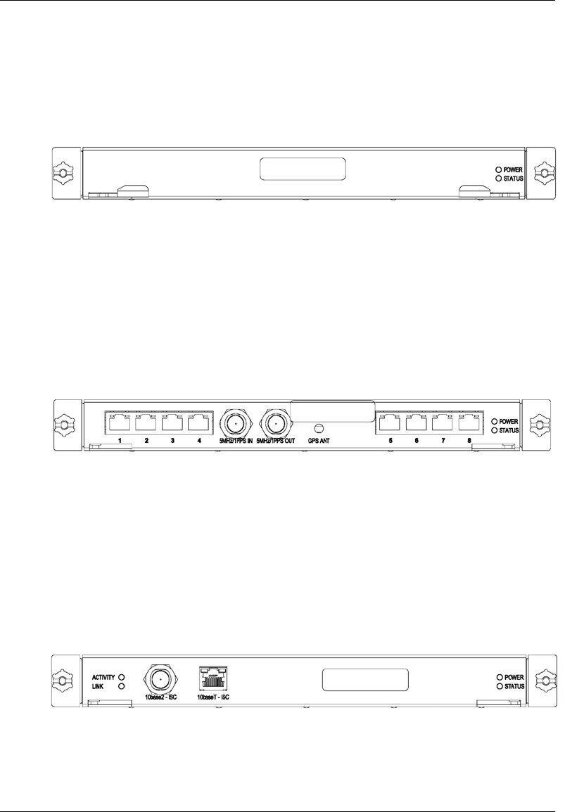
2.2.2 Airlink Interface Chassis (AIC)
The Airlink Interface Chassis (AIC) provides layer 1 (I & Q samples) and layer 2 processing of call
data, including routing of packet data to RadioBlades in RBS, as well as timing to the RBS. Within
the AIC chassis are three assemblies:
• AIC Common RadioFrame Interface Card (CRIC)
• BTS Processing Card + Signal Processing Array Module (BPC+SPAM)—three BPC+SPAM
per AIC in front slots 2, 3, and 4
• Ethernet Rear Transition Module (ERTM)
Figure 10 AIC front view
Figure 11 AIC rear view
ERTM
AIC CRIC
BPC+SPAM
MC-Series System Installation & Testing
System Description
14 RadioFrame Networks, Inc.
2.2.2.1 AIC CRIC
The AIC Common RadioFrame Interface Card (CRIC) provides the Ethernet switch fabric to route
packets to/from the RBS. The AIC CRIC hosts a microprocessor as the primary controller of
BPC+SPAMs. The AIC CRIC has a serial port for local serial access, and eight 10/100BaseT
Ethernet ports that are currently not used.
Figure 12 AIC CRIC ports and indicators
2.2.2.2 BPC+SPAM
BTS Processing Card + Signal Processing Array Module (BPC+SPAMs) are DSP modules that
control the transfer of voice I/Q samples to/from the RBS. BPC+SPAMs perform all necessary
functions of radio link formatting, coding, timing, error control and framing: Voice Control
Procedure (VCP), Associated Control Procedure (ACP), Slot Interchange Procedure (SIP) and
Random Access Protocol (RAP).
Figure 13 BPC+SPAM indicators
2.2.2.3 ERTM
The Ethernet Rear Transition Module (ERTM), located in a rear slot of the AIC, interfaces to the
CRIC via eight RMII ports in the chassis midplane. The ERTM provides Ethernet connectivity
between the AIC and RBS.
Figure 14 ERTM ports and indicators
MC-Series System Installation & Testing
System Description
RadioFrame Networks, Inc. 15
2.2.2.4 AIC Ports
Card Port Description
AIC CRIC Ports 1-8 (RJ45) not currently used
EIA-232 9-pin serial port Nextel technician local serial access
BPC+SPAM N/A N/A
ERTM Ports 1-3 (RJ45) RBS port 10/100 RFN, A, B, and C respectively
Ports 4 (RJ45) BIC ERTM port 2
5MHz/1PPs IN not currently used (no terminator required)
5MHz/1PPs OUT not currently used (no terminator required)
GPS ANT not currently used
2.2.2.5 AIC Indicators
Each card installed in the BIC has a Power and a Status LED. In addition, each RJ45 port has
an Ethernet link LED that indicates connectivity and an Ethernet activity LED that indicates
Ethernet traffic.
LED Indication
Power Indicates power is applied to card
Status Indicates timing synchronization
link activit
y
MC-Series System Installation & Testing
System Description
16 RadioFrame Networks, Inc.
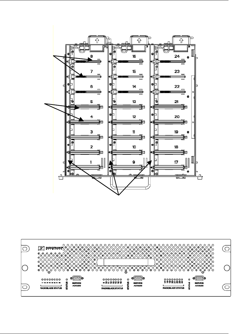
2.2.3 RadioBlade Shelf (RBS)
The RadioBlade Shelf (RBS) houses the iDEN 2-port RadioBlade transceivers, the RadioBlade
transceiver “backplane”, and RF combiner and splitter assemblies. The whole assembly is
housed in a pullout shelf to facilitate field replacement of the RadioBlade transceivers.
The RBS is divided logically into three sets of eight slots. Each set of slots is referred to as a
group—A, B, and C—numbered from left to right when facing the front of the unit. The groups
share redundant DC-DC converters. The slot connectors on the RBS provide the control and data
interface to each RadioBlade transceiver. Each group interfaces with the AIC via a separate
100BaseT Ethernet connection. In addition, a serial console port and status LEDs for each group
are routed to the front panel of the RBS.
RF combining is also accomplished on a per group basis. Integrated into the RBS are 1:8 power
splitters for the Rx path and 8:1 power combiners for the Tx path.
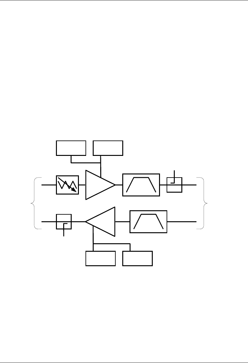
Figure 15 RBS group functional diagram
Serial
Port
100 Base-T
Ethernet to
AIC
Ethernet
Switch
iDEN 2-Port
Radio Blade
8X
RBS Slice
8:1 Power
Splitter
RX RF
Shelf
8:1 Power
Combiner
TX To RF
Shelf
To RadioBlade
RX Port
From
RadioBlade
TX Port
Processor
Alarm
Interface to
RF Shelf
MC-Series System Installation & Testing
System Description
RadioFrame Networks, Inc. 17
Figure 16 RBS interior, top down view
Figure 17 RBS front view
RadioBlades
RadioBlade slots
combiner / splitter housings
A
BC
MC-Series System Installation & Testing
System Description
18 RadioFrame Networks, Inc.
Figure 18 RBS rear view
2.2.3.1 RBS Ports
Front Ports Description
SERVICE ACCESS (A, B, C) Nextel technician local serial access
Rear Ports Description
Tx / Rx (A, B, C) Input and output for RF Shelf
(wiring depends on system configuration)
Fan (A, B, C) Power connector
ALARM INPUT (A, B, C) ALARM serial port on the back of RF Shelf 1, RF Shelf 2, and RF
Shelf 3 (respectively); provides contact closure input from RF
Shelf
10/100 RFN (A, B, C) 100Base-T Ethernet from AIC ERTM Ethernet ports 1, 2, and 3
(respectively)
REF CLOCK not currently used
MC-Series System Installation & Testing
System Description
RadioFrame Networks, Inc. 19
2.2.3.2 RBS Indicators
The front of the RBS has the following LED indicators:
• STATUS indicator for each group—A, B, and C
• RADIOBLADE STATUS indicators, one for each RadioBlade slot in the RBS. LEDs are
arranged by group (8 per group A, B, and C) and are numbered consecutively from left to
right 1 through 24 (A: 1 through 7; B: 8 through16; and C: 17 through 24).
Each RJ45 port (rear only) has an Ethernet link LED that indicates connectivity and an Ethernet
activity LED that indicates Ethernet traffic.
LED Indication
STATUS Indicates timing synchronization for group
RADIOBLADE
STATUS Indicates status of RB: green = operational; red =
alarm condition; not lit = RB not present
2.2.4 iDEN 2-port RadioBlade Transceivers (RadioBlades or RBs)
Each iDEN 2-port RadioBlade transceiver is equivalent to a Motorola Base Radio. Up to 24
RadioBlades are installed into the RadioBlade Shelf. Each RadioBlade has an edge connector to
interface with the slot connector in the RBS. This edge connector provides all data interfaces and
clock inputs to the RadioBlade. The RF interface employs two SMA connectors, one for transmit
and the other for receive.
Figure 19 iDEN 2-port RadioBlade transceiver
Tx port
Rx port
link activit
y
MC-Series System Installation & Testing
System Description
20 RadioFrame Networks, Inc.
2.2.5 RF Shelf
The MC-Series System provides one RF shelf per sector. The RF shelf contains amplifiers, filters,
redundant DC-DC converters, and fans to provide cooling to the power amplifiers (PAs).
The transmit chain includes a variable attenuator for adjusting the Tx power output at the top of
the cabinet, a multi-channel linear power amplifier (PA), a band pass filter, and a sampling port.
The Tx sampling port provides approximately top of the rack (TOR) minus 20 dB output power.
The Tx power output at the top of the rack can be varied by changing the datafill and adjusting
the Tx attenuator setting on the front of the RF shelf (refer to section 7.10 TOR Tx Measurement
Procedure for more information).
The PA is sized to allow sufficient linearity and gain such that a minimum of 10 dBm per carrier
(up to 20 carriers) can be achieved at the top of the rack. The sampling port signal is brought out
to the front of the RF shelf to provide monitoring and testing of the transmit path.
The receive path contains a band pass filter, low noise amplifier (LNA) and a sampling port. As
with the Tx sampling port, the Rx sampling port is brought out to the front panel of the RF shelf.
The Rx sampling port provides approximately top of the rack (TOR) minus 20 dB output power.
Figure 20 RF Shelf functional diagram
TX BPA
RX BPA
LNA
PA
VAR. ATTEN.
TX Test Port
RX Test Port
To RBS
To Top
Of the
Rack
DC-DC
Converter
DC-DC
Converter
DC-DC
Converter
DC-DC
Converter
MC-Series System Installation & Testing
System Description
RadioFrame Networks, Inc. 21
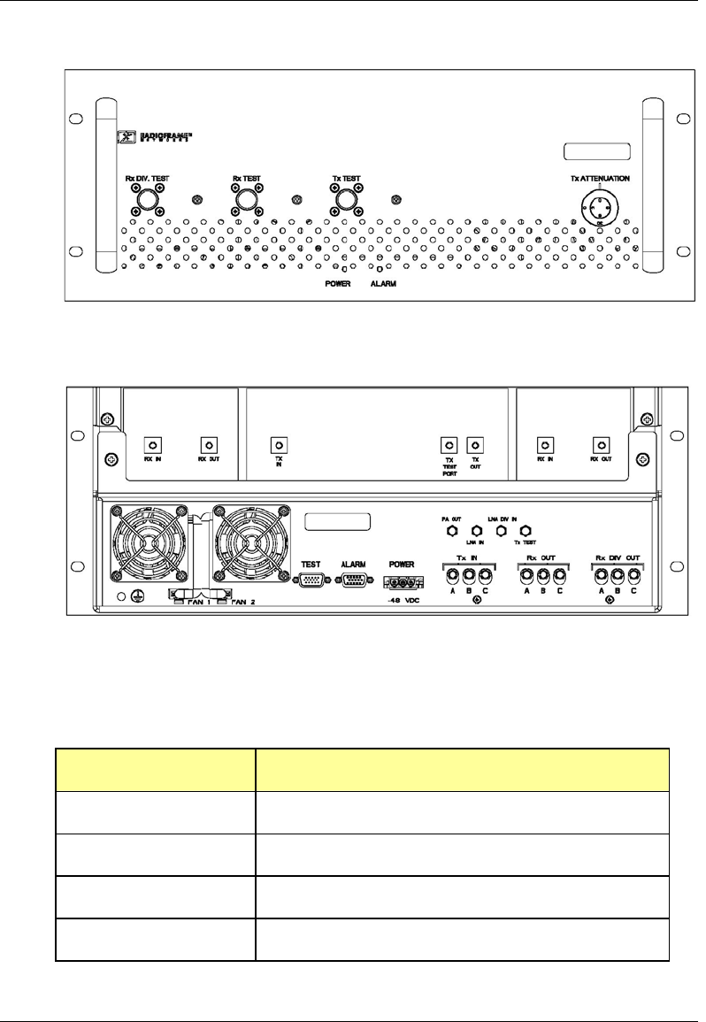
Figure 21 RF Shelf front view
Figure 22 RF Shelf rear view
2.2.5.1 RF Shelf Ports
Front Ports Description
Rx DIV TEST TOR plus 3 dB plus/minus 2 dB
Rx TEST TOR plus 3 dB plus/minus 2 dB
Tx TEST TOR minus 20 dB
Tx ATTENUATION TOR Tx out attenuation adjustment
DIVERSITY

MC-Series System Installation & Testing
System Description
22 RadioFrame Networks, Inc.
Rear Ports Description
RX IN DIVERSITY Connects to TOR Rx 1 Diversity
RX OUT DIVERSITY Connects to RF Shelf LNA DIV IN
TX IN Connects to RF Shelf PA OUT
TX TEST PORT Connects to RF Shelf Tx Test
TX OUT Connects to TOR Tx 1
RX IN Connects to TOR Rx 1
RX OUT Connects to RF Shelf LNA IN
FAN 1 Connects to RF Shelf fan
FAN 2 Connects to RF Shelf fan
TEST Nextel technician local serial access
ALARM Nextel technician local serial access
PA OUT Connects to RF Shelf TX IN
LNA IN Connects to RF Shelf RX OUT
LNA DIV IN Connects to RF Shelf Rx DIV OUT
Tx TEST Connects to RF Shelf TX TEST PORT
Tx IN A, B, C Connects to RBS Tx (A, B, and C, respectively)
Rx OUT A, B, C Connects to RBS Rx (A, B, and C, respectively)
Rx DIV OUT A, B, C Not currently used
MC-Series System Installation & Testing
System Description
RadioFrame Networks, Inc. 23
2.2.5.2 RF Shelf Indicators
The RF Shelf has Power and Alarm LEDs on the front of the unit.
LED Indication
Power Indicates power is applied to card
Alarm Indicates timing synchronization
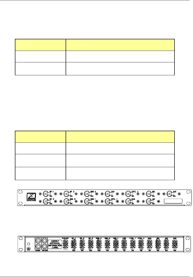
2.2.6 Power Distribution Unit
The Power Distribution Unit (PDU) receives DC input and supplies power via dedicated circuit
breakers to each component in the MC-Series System. Each of the thirteen breakers has a three-
position switch: ON, OFF or TRIPPED. The single alarm output connected to each breaker is
normally closed, and goes open when a breaker is tripped.
Table 2 PDU Circuit Breaker Overview
Breaker Amps Quantity
10 7
6 2
3 4
Figure 23 PDU front view
Figure 24 PDU rear view
MC-Series System Installation & Testing
System Description
24 RadioFrame Networks, Inc.
2.2.7 Cabinet
The MC-Series System cabinet is an APW Pioneer Seismic Series standard 19” equipment
cabinet with vented, lockable side panels, lockable front and rear doors, and a computer shelf on
the inside of the front door. The cabinet is rated for seismic zone 4 and operates in an
environment of 0° to +40° C ambient. External RF connectors are flush with the top of the cabinet
in a recessed bulkhead. For more information, refer to the cabinet manufacturer’s documentation
shipped with the MC-Series System.
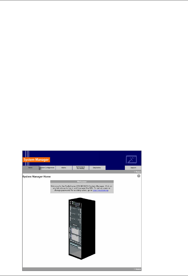
2.3 System Manager Software
The MC-Series System is managed and configured via RadioFrame Network's System Manager,
a Web-based graphical management system, which is accessible via any IP-based connection.
System Manager provides Operations personnel with remote access and control, including
configuration, alarm monitoring, triage/troubleshooting and system statistical reporting. All RFN
MC-Series Systems include System Manager as standard equipment. Core System Manager
functions include:
• Software Download (both locally and remotely)
• X.733 Alarming
• Configuration Management
• Diagnostics and Troubleshooting
• Call Statistics and Uptime
• RF Performance Metrics (e.g., Uplink SQE, Noise Floor, etc.)
• Test and Maintenance (e.g., automated BER testing)

MC-Series System Installation & Testing
System Description
RadioFrame Networks, Inc. 25
2.4 Non-RFN Hardware
Non-RFN hardware for the MC-Series System must be procured and then installed in order for
the MC-Series System to be complete.
2.4.1 integrated Site Controller (iSC-3)
The MC-Series System includes a pair of redundant integrated Site Controllers, or iSC-3s, which
are connected to the macro network through a Channel Service Unit (CSU). The connection
between the iSC and the MC-Series System is via two coaxial interfaces. The first is a 10base-2
Ethernet connection to provide data communications. This connection is made directly to the MC-
Series System and does not require an external media converter. The second connection is a 1
pps reference for system timing.
For more information about the iSC-3, refer to the Motorola document Gen 3 Site Controller
System Manual, 68P80801E30-O.
2.4.2 Environmental Alarm System (EAS)
The Environmental Alarm System (EAS) provides a central location for site alarm signal
processing. The EAS monitors site environmental conditions, including AC power, smoke alarms,
intrusion alarms, antenna tower lights, etc.
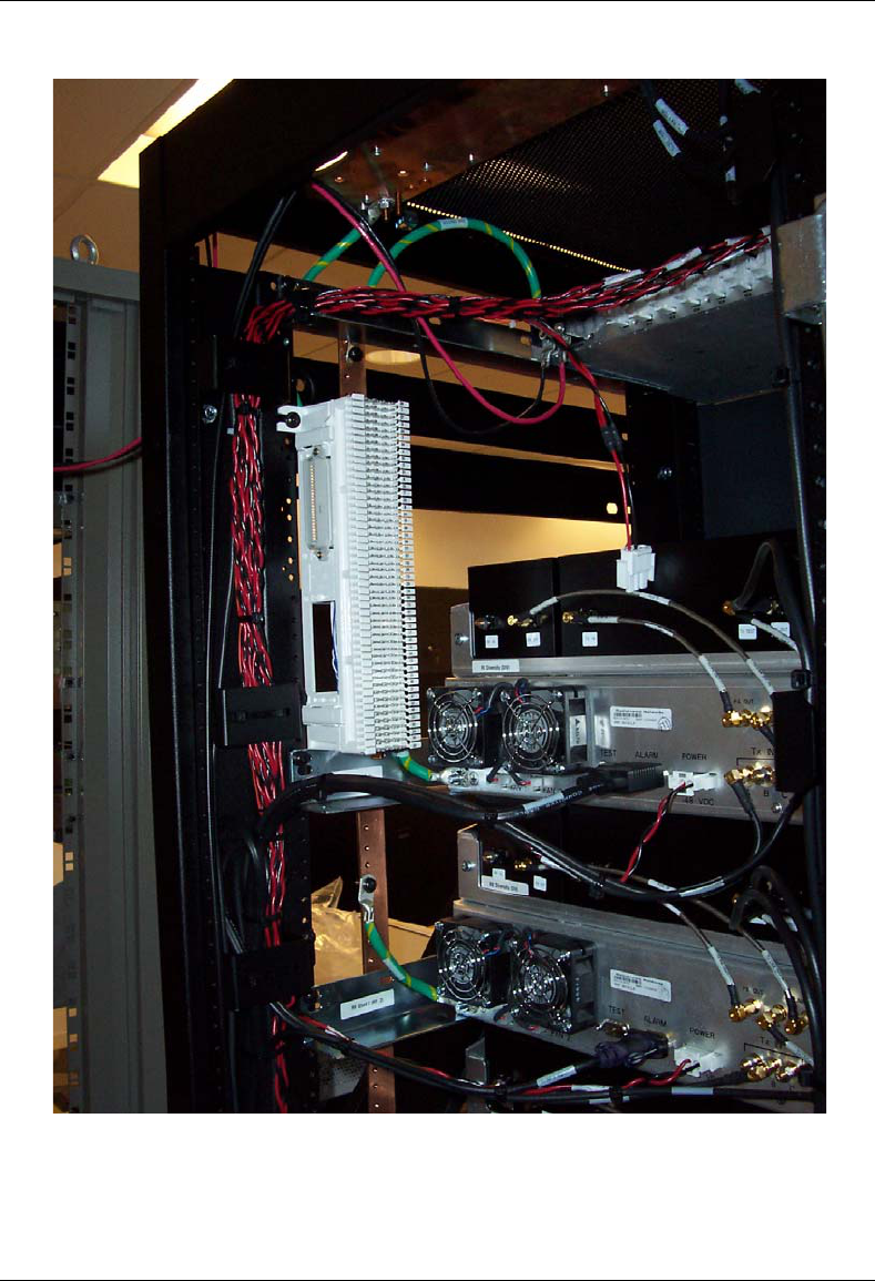
Each of the site alarm contacts are normally closed and connected to the EAS through a 50-pin
Champ cable that connects to a punch block. All alarm contact pairs must be dry (isolated from
ground). Most alarm connections are inputs. Outputs provide a dry relay closure rated at 0.5
Amps, 30 Vrms or 60 Vdc, 10VA max.
Plan to implement EAS alarm blocks, wiring, and sensors as required depending on the
installation:
• If the MC-Series System cabinet is deployed as a standalone unit (i.e., as the only cabinet in
the area), plan to provide standard Nextel facility environmental sensors, wiring, and
connections. Plan to install the EAS alarm blocks on the Telco board on the wall of the space
where the MC-Series System cabinet is located, and locate the high-temperature and low-
temperature sensors there. Plan to provide conduit or other wire routing from a door sensor,
HVAC units (if separate HVAC units are installed for the installation), and AC power failure /
surge arrestor failure sensors.
• If the MC-Series System cabinet is deployed as one of a group of cabinets (i.e., in an RF
“hotel”), plan to provide standard Nextel facility environmental sensors, wiring, and
connections for one of the cabinets. The alarm facilities for the other cabinets will generally
not be used. For the cabinets with unused alarms, plan to strap all alarm inputs with 24AWG
solid-conductor wire (e.g., wire from a Category 5 cable). Plan to extend the 25-pair alarm
cables with pre-connectorized 25-pair extension cables as needed to allow the alarm blocks
to reach the wall space where they are to be mounted. Do not plan to leave the alarm blocks
in the cabinets or otherwise not mounted.
• If the alarm block must be installed within the MC-Series cabinet, mount as shown in the
following photograph.
For more information about the iSC-3, refer to the Motorola document Gen 3 Site Controller
System Manual, 68P80801E30-O.
MC-Series System Installation & Testing
System Description
26 RadioFrame Networks, Inc.
Figure 25 Punch block location within the MC-Series rack.

MC-Series System Installation & Testing
System Description
RadioFrame Networks, Inc. 27
2.4.3 Channel Service Unit (CSU)
The Channel Service Unit (CSU) provides the T1 connection between the iSC-3 and the
telephone company that provides the T1 line. The CSU provides surge protection to the T1 line
and loop-back testing for the telephone company.
For more information about the CSU, refer to the manufacturer's documentation.
2.4.4 GPS Antenna System
The Global Positioning System (GPS) antenna provides GPS signals to the iSC-3, which
constructs the timing reference for the MC-Series System hardware. One GPS antenna with a
dedicated 50ohm coax is required for each iSC-3.
2.4.5 Powerplant
The MC-Series System cabinet is powered by a nominal –48VDC powerplant supplied by the
customer. The powerplant may be installed in the cabinet or used externally. The cabinet is
shipped with a Power Distribution Unit (PDU) installed in the cabinet. The PDU contains circuit
breakers that provide overcurrent protection for MC-Series loads.
2.5 Specifications
2.5.1 Dimensions
Equipment Dimensions Supplier Component
Width Depth Height
RadioFrame Networks cabinet 23.5” 25.5” 79” 42U
BIC 19” 13” 7” 4U
AIC 19” 13” 7” 4U
RBS 19” 13” 7” 4U
RF Shelf 19” 13” 7” 4U
PDU 19” 10” 1.75” 1U
Non-RFN iSC-3 19” 9” 1.75” 1U
EAS 19” 15” 1.75” 1U
CSU 19” 12.5” 1.75” 1U
MC-Series System Installation & Testing
System Description
28 RadioFrame Networks, Inc.
2.5.2 Weight
Supplier Component Weight
RadioFrame Networks cabinet 579 lbs (shipped)
611 lbs (fully loaded)
BIC 22 lbs
AIC 22 lbs
RBS 60 lbs (24 RBs)
RF Shelf 165 lbs
(55 lbs each)
PDU 10 lbs
Non-RFN iSC-3 16 lbs
(8 lbs each)
EAS 6 lbs
CSU 10 lbs
2.5.3 Floor Loading
Supplier Component Floor Loading
RadioFrame Networks cabinet 200 lbs per sq ft (includes 25% safety factor)
2.5.4 Power Requirements
Supplier Component Power
RadioFrame Networks BIC -42 to -56 VDC
AIC
-42 to -56 VDC
RBS
-42 to -56 VDC
RF Shelf
-42 to -56 VDC
PDU -42 to -56 VDC
Non-RFN iSC-3 -40 to -60 VDC
EAS
-40 to -60 VDC
CSU
-40 to -60 VDC
2.5.5 Power Consumption*
Assembly Qty Power[W] Per Assembly Total Power[W] Current[A] @ -48Vdc
RF Shelf 3 68.0 216.0 4.4
MC-Series System Installation & Testing
System Description
RadioFrame Networks, Inc. 29
Assembly Qty Power[W] Per Assembly Total Power[W] Current[A] @ -48Vdc
RBS
(24 RadioBlades) 1 67.2 67.2 1.4
BIC 1 110.0 110.0 2.3
AIC 1 115.2 115.2 2.4
ISC 2 24 48.0 1.0
EAS 1 19.2 19.2 0.4
CSU 1 40 40 0.8
TOTAL 615.6 12.7
* Panduit termination lugs are required for installation.
2.5.6 Grounding*
Supplier Component Ground Resistance (ohms)
RadioFrame Networks cabinet
* Termination lugs are required for installation.
2.5.7 Environment
Value Parameter Condition
Min Typ Max
Unit
Normal operation 0 27 40 °C Ambient Temperature
Storage -40 +70 °C
Normal operation relative,
non-condensing
10 90 %
Humidity
Storage, non-condensing 5 90 %
Altitude Relative to mean sea level. -60 1800 m
Shock 40 G
Vibration Level 4 earthquake; meets or
exceeds GR-63-CORE
Earthquake Environment
NEBS requirements
99.9 % pass
UL Pollution Degree 3 99.9 % pass
Transport Vibration NSTA, ISTA compliant 99.9 % pass
MC-Series System Installation & Testing
System Description
30 RadioFrame Networks, Inc.
2.5.8 Heat Load
Supplier Component BTUs per Hour
RadioFrame Networks BIC 340
AIC 340
RBS 320
RF Shelf 680
PDU 0
Non-RFN iSC-3 140
EAS 170
CSU 17
2.5.9 RF Performance
The MC-Series System will meet the emissions mask requirements per FCC Part 90, section
90.691.
2.5.9.1 Frequency of Operation
Band Receive Frequency (MHz) Transmit Frequency (MHz)
800E 806.0125 to 824.9875 851.0125 to 869.9875
2.5.9.2 Transmitter Performance Summary
Value Parameter 1Condition
Min Typ Max
Unit
2Tx Output Power per
carrier (maximum)
Typical output power +8.0 +10 +12 dBm
Tx Power Output
Range per carrier
-20 +10 dBm
Tx Output Power
Variation
-20dBm ≤ Pout ≤ +10 dBm
851.0125 ≤ f ≤ 869.9875 MHz
-2.0 2.0 dB
Transmit port VSWR Referenced to a 50 ohm
impedance
2:1 -
Downlink Signal Quality
Estimator (SQE)
Average value 30 dB
Occupied bandwidth Per carrier 18.5 kHz
RF Frequency
Tolerance (TX)
Average frequency ± 50 Hz
Note 1: Unless otherwise stated, all values are referenced to the top of the rack.
MC-Series System Installation & Testing
System Description
RadioFrame Networks, Inc. 31
Note 2: At maximum rated RF output power, all spurious and harmonic emissions should be at the noise floor. No
combination of IM products or any other spurious emissions generated in the transmitting equipment should exceed the
underlying noise floor in the operating band. Also, the Tx output power level is a function of the datafill parameters as well
as the RF shelf attenuator setting.
2.5.9.3 Receiver Performance Summary
Value Parameter 1Condition
Min Max
Unit
2% BER -106 -36 dBm
Rx Input Level Absolute Maximum where
no damage occurs
+10 dBm
Residual BER Input signal of –80 dBm 0.1 %
Input IP3 Single channel input +10 dBm
Adjacent Channel
Selectivity*
Quad-channel input -32 dBc
2IMD Immunity Prx = -103 dBm, BER<2%
∆ f1 = ± 1 MHz
∆ f2 = ± 2 MHz
-50 dBm
Note 1: Unless otherwise stated, all values are referenced to the top of the rack.
Note 2: Two-tone test ∆ f1 is a CW interferer, ∆ f2 is an iDEN modulated interferer; refer to RFN test document.
2.5.9.4 Transmit Filter Specification
Value Parameter 1Condition
Min Max
Unit
Pass Band 851.0125 869.9875 MHz
Pass Band Insertion
Loss
Referenced to a 50 ohm
impedance
2.0 dB
Pass Band Ripple Referenced to a 50 ohm
impedance
-0.5 +0.5 dB
Stop Band
Attenuation
Referenced to a 50 ohm
impedance
-60 dBc
Note 1: Unless otherwise stated, all values are referenced to the top of the rack.
Refer to Appendix E for filter curve.
2.5.9.5 Receive Filter Specifications
Value Parameter 1Condition
Min Max
Unit
Pass Band 806.0125 824.9875 MHz
Pass Band Insertion
Loss
Referenced to a 50 ohm
impedance
1.0 dB

MC-Series System Installation & Testing
System Description
32 RadioFrame Networks, Inc.
Value Parameter 1Condition
Min Max
Unit
Pass Band Ripple Referenced to a 50 ohm
impedance
-0.5 +0.5 dB
Stop Band
Attenuation
Referenced to a 50 ohm
impedance
-60 dBc
Note 1: Unless otherwise stated, all values are referenced to the top of the rack.
Refer to Appendix E for filter curve.

MC-Series System Installation & Testing
Pre-Installation
RadioFrame Networks, Inc. 33
3 Pre-Installation
This section provides pre-installation information for the MC-Series System at a Nextel site. Prior
to installation, prepare the site with all associated antennas, phone lines, and other related site
equipment.
3.1 Site Planning
For each of the ensuing site planning subsections, complete the following:
a. Identify work to be completed by Nextel technicians and outside contractors.
b. Create a list of materials to be used by Nextel technicians in completing the work.
c. Create statements of work (SOWs) for work to be completed by outside contractors.
3.1.1 Space Requirements
Establish the following specifications to meet National Fire Protection Associations (NFPA) Code
and American Society of Heating, Refrigerating, and Air Conditioning Engineers (ASHRAE)
standards. Any local regulations, as applicable, shall also be adhered to.
• Ceiling height shall be at least 8'6” above a finished floor to allow enough space for the height
of the cabinet and cable access at the top of the cabinet.
• Door dimensions shall be at least 3' wide and 6'8” high to allow equipment access.
• 36 in. shall be maintained in front of electrical panel boards (NFPA 70, Article 110-26).
• 36 in. aisle shall be maintained in front of the MC-Series System cabinet.
• 30 in. aisle shall be maintained in back of the MC-Series System cabinet.
• No additional space is required on cabinet sides.
• 4' x 4' wall space shall be provided for termination of T1, alarm blocks, environmental
sensors, and the master ground bar.
• Rack space for associated hardware, such as a DAS system or an outside powerplant, may
be required.
• If battery backup is not provided by the facility owner, include space for an auxiliary backup
battery rack. Refer to Nextel standards for sizing and placement.
• As required, install overhead cable tray to support cables to and from the MC-Series System
cabinet per the National Electric Code (NEC), which states: neither the ceiling grid nor its
supports may be used to support cable tray or wiring.
3.1.2 Floor Loading
Refer to section 2.5.3 Floor Loading for specifications.

MC-Series System Installation & Testing
Pre-Installation
34 RadioFrame Networks, Inc.
3.1.3 Anchoring
Anchor the MC-Series System cabinet to the floor using suitable anchors (Hilti or equal). Do not
mount the MC-Series System cabinet on casters.
3.1.4 Seismic Zone Installation
All RadioFrame Networks equipment is seismically rated to withstand vibrations of a Level 4
earthquake. The property owner is responsible for any damage to RFN equipment due to building
or cabinet structures that are not rated to withstand vibrations of a Level 4 earthquake, or not
secured to withstand vibrations of a Zone 4 earthquake.
Ensure that a certified architect specializing in earthquake-resistant installation provides seismic
designs and recommendations in areas where the potential loss of the site may outweigh
associated costs of earthquake-resistant design. PE stamped drawings shall be provided before
the installation proceeds.
3.1.5 Cooling of Equipment
Ensure that the location provides sufficient cooling for the MC-Series System cabinet. Refer to
section 2.5.8 Heat Load for BTUs generated by the MC-Series System.
3.1.6 Power
Ensure that a DC power source is available that can supply full power requirements for both the
MC-Series System cabinet and all ancillary equipment for the installation. This power source may
be a bulk DC power source, an internally mounted DC powerplant, or an external DC powerplant.
For internal or external DC powerplants, backup batteries may or may not be required, depending
on whether or not the powerplant is driven from a UPS (Uninterruptible Power Supply). Refer to
Nextel standards for DC power design.
Any installation of AC power conductors shall be done by a licensed, bonded, and insured
electrician. Follow standard Nextel design practices for AC and DC power circuits including any
required AC surge protection. Identify any contract labor and materials required.
Refer to section 2.5 Specifications for DC power requirements. Plan to use termination lugs.
Required crimp tool is CT-1700.
3.1.7 Grounding
The MC-Series System cabinet must be grounded to either a defined equipment grounding
system in a Nextel facility or to the building grounding electrode in a customer facility. Plan to
install a grounding system for the MC-Series System cabinet and ancillary hardware. Refer to
Chapter 7 and Appendix C of Motorola R56, as modified by Nextel, for grounding standards. The
Master Ground Bar (MGB) will be installed on the wall on the telco board. Plan to use termination
lugs. Required crimp tool is CT-1700.

MC-Series System Installation & Testing
Pre-Installation
RadioFrame Networks, Inc. 35
3.1.8 GPS Antennas
Refer to the Motorola Gen 3 Site Controller System Manual, 68P80801E30-O document and
Nextel standards for GPS antenna design and installation. Per the NEC (1) any cabling run
through an air plenum shall be plenum-rated, and (2) cabling is not to be laid on or suspended
from any ceiling grid or attached to the grid supports. Identify any contract labor and materials
required.
3.1.9 T1 Service
Install T1 cabling from the point of demarcation to the MC-Series System cabinet, and providing
UL497B surge protection for the T1 circuit involved. Use standard Nextel-approved surge
arrestors for the T1 circuit. Per the NEC (1) any cabling run through an air plenum shall be
plenum-rated, and (2) cabling is not to be laid on or suspended from any ceiling grid or attached
to the grid supports. Identify any contract labor and materials required to extend the T1 service
from the demarcation point to the MC-Series System Cabinet. For ease of maintenance,
RadioFrame Networks recommends locating the demarcation point (SmartJack) in the same
space as the MC-Series System cabinet.
Refer to the Motorola Gen 3 Site Controller System Manual, 68P80801E30-O document and
Nextel standards for T1 design and installation.
3.1.10 Alarm Blocks
Various alarms or sensors are installed within the Nextel site building. All alarm wiring terminates
at the Environmental Alarm System (EAS) location within the cabinet. All alarm wires shall be
tagged and labeled with the appropriate alarm item. All contacts will be normally closed, dry, and
isolated from ground. Alarm wire will be neatly run and secured using nylon cable ties/clamps
every three feet to walls and existing cable tray. All alarm wiring shall be two-wire, 22 AWG.
3.1.10.1 Environmental Alarm System (EAS)
Plan to implement EAS alarm blocks, wiring, and sensors as required depending on the the
installation:
If the MC-Series System cabinet is deployed as a standalone unit (i.e., as the only cabinet in the
area), plan to provide standard Nextel facility environmental sensors, wiring, and connections.
Plan to install the EAS alarm blocks on the Telco board on the wall of the space where the MC-
Series System cabinet is located, and locate the high-temperature and low-temperature sensors
there. Plan to provide conduit or other wire routing from a door sensor, HVAC units (if separate
HVAC units are installed for the installation), and AC power failure / surge arrestor failure
sensors.
If the MC-Series System cabinet is deployed as one of a group of cabinets (i.e., in an RF “hotel”),
plan to provide standard Nextel facility environmental sensors, wiring, and connections for one of
the cabinets. The alarm facilities for the other cabinets will generally not be used. For the cabinets
with unused alarms, plan to strap all alarm inputs with 24AWG solid-conductor wire (e.g., wire
from a Category 5 cable). Plan to extend the 25-pair alarm cables with pre-connectorized 25-pair
extension cables as needed to allow the alarm blocks to reach the wall space where they are to
be mounted. Do not plan to leave the alarm blocks in the cabinets or otherwise not mounted.

MC-Series System Installation & Testing
Pre-Installation
36 RadioFrame Networks, Inc.
3.2 Scheduling / Logistics
a. Procure all non-RFN hardware. Refer to Nextel documentation for procurement of iSC-3s,
EAS, and CSU.
b. Procure the materials identified in 3.1 required by Nextel technicians to complete the
installation.
c. Initiate the contracts necessary to engage outside contractors to complete the installation
work necessary, including any design or engineering work necessary for seismic areas. As
noted previously, any installation requiring seismic certification requires a formal design and
installation package from an architect skilled in this area.
d. Follow standard Nextel RF Operations and Site Development procedures for scheduling (a)
all installation activity and (b) all necessary datafill work.
Planning should now be complete for the following tasks:
• Securing the MC-Series System cabinet to the mounting surface
• Installing AC or DC power cabling and DC powerplant
• Installing grounding
• Installing T1 cabling
• Installing a GPS antenna system
• Installing facility alarms
• Adding HVAC
3.3 MC-Series System Installation Kit
RadioFrame Networks provides the following materials in an installation kit shipped with the
MC-Series System:
Qty Item Usage
2 GPS surge arrestors, 2.4 GHz bulkhead N-type, inline TOR
2 RG58/U, 1 meter coax cable, BNC M to BNC M BIC to iSC
2 LMR-195-PVC, 84” cable, N-type iSC to GPS at TOR
20 10/32 Philips thread cutting screw mounting non-RFN HW in rack
4 Lifting eyelet bolt cabinet installation
1 Non-disposable ESD wrist strap ESD prevention
1 Cabinet manufacturer’s installation manual mounting cabinet
4 SMA terminators spares for RF shelf reconfigurations

MC-Series System Installation & Testing
Pre-Installation
RadioFrame Networks, Inc. 37
3.4 iDEN Configuration
The MC-Series System supports WiDEN (Quad BRs) and the use of four adjacent channels and
remote control of these settings. Plan to set up the MC-Series System according to the base
radio (BR) parameters specified in the site datafill for the site, including cabinet, position, and
Quad. Corresponding parameters will be set using the System Manager iDEN Configuration page
during system set up (section 5.5). For more information about site datafill parameter settings,
refer to the iDEN OMC-R Configuration Management Parameters Technical Manual,
68P80802E10.
3.4.1 Cabinet and Position Settings
Each RadioBlade in the MC-Series System operates as a BR. The system ships with default
cabinet and position settings that must be changed during system set up to match the site datafill
BR settings. The iSC then sets up each RadioBlade (BR) with a specific carrier.
3.4.2 Quad BRs
Within the RadioBlade Shelf (RBS), RadioBlades are arranged in three groups of up to 8
RadioBlades. A maximum of one quad BR can be configured in each group. To do this,
determine the cabinet/position settings, if any, to be assigned the quad BR from the parameters
in the datafill. If a quad BR is selected, four RadioBlades from that group will be assigned to a
single BR, leaving the remaining four RadioBlades to be used as EBRCs. When configuring a
quad BR in the datafill (for use in the MC-Series), the number of carriers must be equal to four.
The MC-Series System also supports EBRCs configured with adjacent channels. Instead of
configuring a quad BR in the datafill, configure four EBRCs using four adjacent channels (each
adjacent BR is assigned a separate cabinet/position).
3.4.3 Sectorization
In an omni (single-sector) configuration, all BRs are assigned to the same sector. In a 2- or 3-
sector configuration, each group (A, B, and C) may be assigned to a different sector. In this case,
all RadioBlades within the group must be assigned to the same sector—multiple sectors cannot
be assigned within the same group.

MC-Series System Installation & Testing
Installation
38 RadioFrame Networks, Inc.
4 Installation
4.1 Site Inspection
Following all construction work, both exterior and interior, the site and facility shall be in a suitable
condition for the installation of communications equipment.
In general, the following considerations need to be observed: list section 3.1 items except T1
• Facility is secured with lockable doors.
• HVAC
• Grounding
• Interior of facility shall be free of excessive dust.
• All refuse related to the installation tasks shall be removed.
Consideration should be exercised when laying out a site to allow primarily for all code
requirements for spacing, and then the most efficient use of space. Special attention shall be
given to future expansion with regard to cable runway heights, electrical outlet placement, and
equipment placement.
4.2 Receipt of Equipment
The MC-Series System is provided pre-installed in a standard 79” tall, 19” wide EIA- compliant
cabinet with the following equipment:
• BIC (BTS Interface Chassis)
• AIC (Airlink Interface Chassis)
• RBS (RadioBlade Shelf)
• RF Shelf (3 each)
• PDU (Power Distribution Unit)
• MC-Series System Installation Kit
4.2.1 Equipment Inspection
Inspect the equipment immediately upon receipt. If obvious damage has occurred to the shipping
container before unpacking, contact the shipping agent. Ask that a representative of the shipping
company be present while the equipment is unpacked.
Check for the following:
• loose or damaged equipment in the pre-installed cabinet
• dents, scratches, or other damage on all sides of each component
If any equipment is damaged, contact the shipping company immediately, then a Nextel
representative.
MC-Series System Installation & Testing
Installation
RadioFrame Networks, Inc. 39
4.2.2 Equipment Inventory
Check all MC-Series System equipment against the itemized packing list to ensure receipt of all
equipment. If available, check the sales order with the packing list to account for all equipment
ordered. Contact the Nextel representative to report missing items and for additional information.
4.3 Mounting the MC-Series System Cabinet
Refer to the manufacturer’s documentation (included with the MC-Series System Installation Kit)
for installation procedures for mounting and securing the MC-Series System cabinet.
Warning!
Always use two or more persons whenever moving a cabinet. A fully
configured equipment cabinet weighs approximately 800 lbs (360 kg).
4.4 Mounting Non-RFN Equipment in the MC-Series System Cabinet
This section describes procedures for mounting the following non-RFN equipment in the MC-
Series System cabinet:
• iSC-3 (two)
• EAS
• CSU
Warning!
Any equipment installed in the MC-Series System cabinet shall be UL listed.
Warning!
User equipment that is installed shall not draw a combined current of more
than 5 amps. This combined total shall be determined from the marked current
rating label of the equipment to be installed.
MC-Series System Installation & Testing
Installation
40 RadioFrame Networks, Inc.
Figure 26 MC-Series System rack locations for non-RFN hardware
future RBS
(2 & 3)
reserved for
powerplant
RBS 1
MC-Series System Installation & Testing
Installation
RadioFrame Networks, Inc. 41
4.4.1 iSC-3s
1 While supporting the iSC-3, slide the iSC-3 into the cabinet mounting position.
Mount the iSC-3 in the location shown in the cabinet illustration earlier in this section. If
necessary, install side rails in the mounting position in the rack.
2 Secure the iSC-3 to the cabinet mounting rails using the four mounting screws provided with
the unit. Tighten the screws to 4.5 Nm (40 in-lb).
3 Connect the RFN-provided ground cable (P/N 820-0609-10; ISC1 to GND BAR) between the
cabinet ground bar and the grounding lug on the rear of the iSC-3, and ensure the connection
is tight.
4 Connect the RFN-provided power cable (P/N 820-0613-50; PDU-CTRL_1 to ISC1) between
the iSC-3 power and the CTRL circuit breaker on the PDU (CTRL 1 for the primary iSC and
CTRL 2 for the secondary iSC).
5 Repeat steps 1 through 4 to mount the secondary iSC-3 (cable labels will show ISC2 instead
of ISC1).
6 Connect the two iSC-3s according to Nextel’s installation procedure.
7 Using the RFN-provided coax cable (P/N 111-0001-02; BIC-ERTM 5MHz IN to ISC1 REF
OUT-1), connect the primary iSC-3 port SITE REF OUT 1 to the BIC ERTM port 5MHz IN.
8 Terminate the two remaining SITE REF OUT ports on the primary iSC-3, and terminate all
three SITE REF OUT ports on the secondary iSC-3.
9 Using the RFN-provided coax cable (P/N 111-0001-02; BIC-CRTC to ISC1 REF OUT-1),
connect the primary iSC-3 port 10B2-1 to the BIC CRTC port 10Base2 ISC.
10 Terminate the two remaining iSC-3 10B2 ports on the primary iSC-3, and terminate all three
10B2 ports on the secondary iSC-3.
For complete cabling information, refer to Appendix C Cabling Diagrams: 3-Sector
Configuration.
ISC1
BIC
MC-Series System Installation & Testing
Installation
42 RadioFrame Networks, Inc.
4.4.2 EAS
1 While supporting the EAS, slide the EAS into the cabinet mounting position.
Mount the EAS in the location shown in the cabinet illustration earlier in this section.
2 Secure the EAS to the cabinet mounting rails using the four mounting screws provided with
the unit. Tighten the screws to 4.5 Nm (40 in-lb).
3 Connect the RFN-provided ground cable (P/N 820-0609-10; EAS to GND BAR) between the
cabinet ground bar and the grounding lug on the rear of the EAS, and ensure the connection
is tight.
4 Connect the RFN-provided power cable (P/N 820-0616-50; EAS to PDU-EAS) between the
EAS power and the EAS circuit breaker on the PDU.
5 Connect EAS to each iSC-3 according to Nextel’s installation procedure.
6 Connect the RFN-provided contact closure alarm wires from the CONTROL port on the EAS
(RJ45) to the STATUS connectors on the PDU (Molex).
For complete cabling information, refer to Appendix C Cabling Diagrams: 3-Sector Configuration.
4.4.3 CSU
Warning!
Always connect the power cable to the CSU before connecting the power cable
to the PDU.
1 Remove the cabinet mounting rails from the CSU mounting location.
2 While supporting the CSU, slide the CSU into the cabinet mounting position.
Mount the CSU in the location shown in the cabinet illustration earlier in this section. As
necessary, follow the equipment manufacturer's installation procedure for mounting the CSU
in a 19” standard EIA-compliant rack.
3 Connect the RFN-provided ground cable (P/N 820-0609-10; CSU to GND BAR) between the
cabinet ground bar and the grounding lug on the rear of the CSU, and ensure the connection
is tight.
EAS
PDU

MC-Series System Installation & Testing
Installation
RadioFrame Networks, Inc. 43
4 Connect the RFN-provided power cable (P/N 820-0615-50; CSU to PDU-CSU) to the CSU
power.
5 Connect the other end of the power cable to the circuit breaker on the PDU.
6 Connect the CSU to each iSC-3 according to Nextel’s installation procedure.
For complete cabling information, refer to Appendix C Cabling Diagrams: 3-Sector Configuration.
4.5 Mounting Auxiliary Equipment
Follow Nextel's procedures for mounting the following auxiliary equipment:
• Powerplant
• Backboard
• Surge arrestors
• Alarm blocks
• Environmental sensors
4.6 Cabinet-to-Site Cabling
Follow Nextel's procedures for installing the following wiring at the site, and then complete the
procedures in this section to complete the cabinet-to-site cabling. See the following illustration for
top of the rack connections.
• Grounding
• T1
• GPS surge arrestors
• EAS alarm cabling
• RF (Tx / Rx / Rx diversity)
• Power
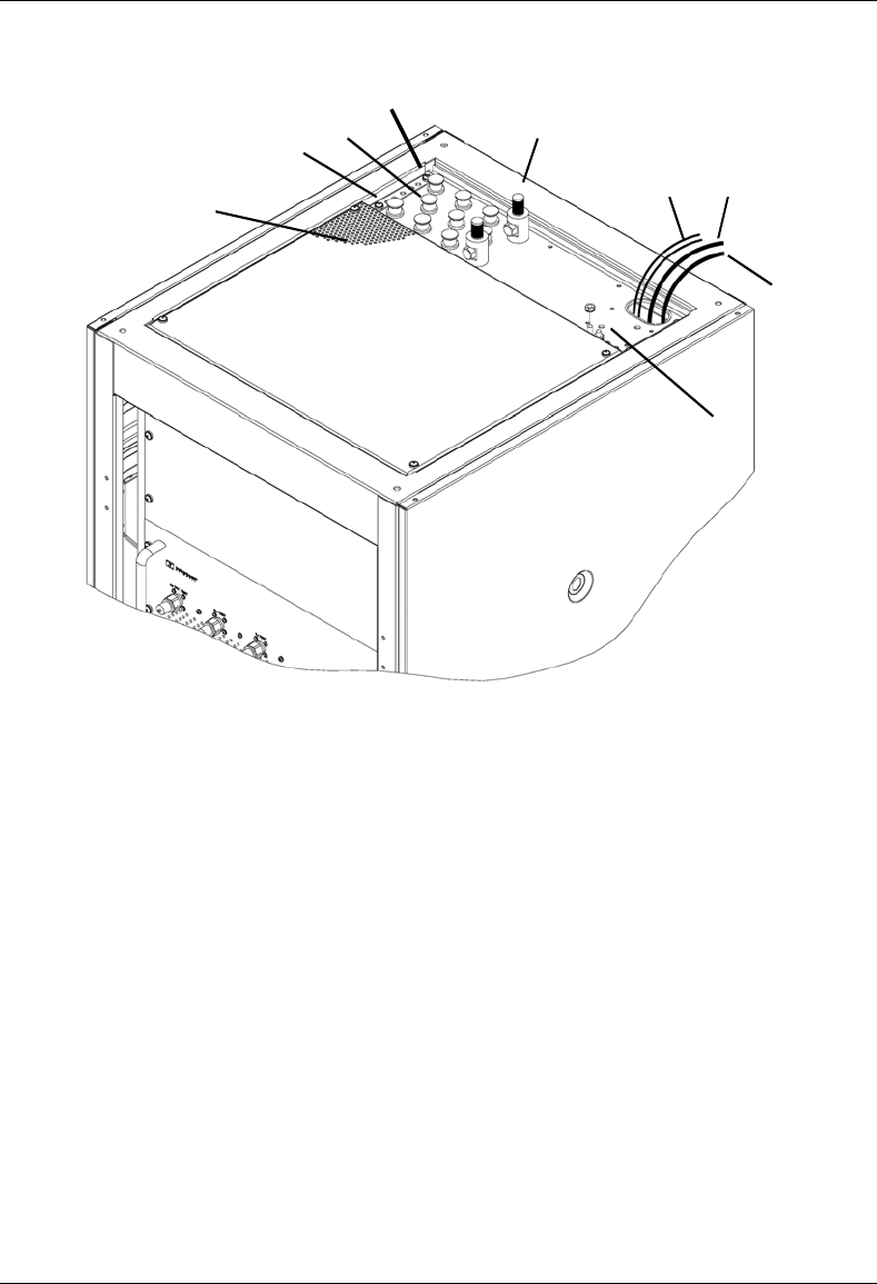
MC-Series System Installation & Testing
Installation
44 RadioFrame Networks, Inc.
Figure 27 Top of the rack (TOR) cabling and equipment
4.6.1 Grounding
1 Ground the cabinet ground bar to the site according to Nextel’s installation instructions using
6 and 8 gauge lugs.
2 Connect the site ground to the ground at the top of the rack according to Nextel’s installation
procedures (see the previous diagram for ground location at the top of the rack).
4.6.2 T1
1 Follow Nextel’s procedure for routing the site T1 cable through the top of the cabinet as
shown in the previous diagram.
2 Connect the T1 cable to the CSU according to Nextel’s installation instructions.
Tx Rx
Diversity
ventilation
GPS
DC PWR T1
EAS alarm
cabling
GND

MC-Series System Installation & Testing
Installation
RadioFrame Networks, Inc. 45
4.6.3 GPS Surge Arrestor
Follow Nextel’s procedure for installing GPS equipment at the site. Then complete the following
procedure:
1 Install the two RFN-provided GPS surge arrestors at the top of the rack as shown in the
previous diagram.
NOTE: Make sure the element on the side of the surge arrestor is accessible, depending on
the site configuration.
2 Connect the cable from GPS surge arrestor to the primary iSC-3, rear port GPS.
(P/N820-0620-00; GPS-ISC to GPS_1 TOR).
3 Connect the cable from the second GPS surge arrestor to the secondary iSC-3, rear port
GPS (P/N820-0620-00; GPS-ISC to GPS_2 TOR).
4 Connect each GPS surge arrestor to the GPS antenna coax according to Nextel’s installation
procedures.
4.6.4 EAS Alarm Cabling
1 Follow Nextel’s procedure for routing the two 50-pair alarm cables through the top of the
cabinet, as shown in the previous (top-of-the-rack) illustration.
2 Connect the two 50-pair alarm cables to the back of the EAS:
EAS: USER ALARM / CONTROL
EAS: SYSTEM ALARM / CONTROL
3 Terminate the two 50-pair alarm cables to the two blocks on the backboard, making sure that
each cable is connected to its specific block.
4.6.5 RF (Tx / Rx / Rx diversity)
The MC-Series System cabinet provides the following RF loads at the top of the rack for
connection to the site RF distribution system:
• Tx 1, Tx 2, Tx 3
• Rx 1, Rx 2, Rx 3
• DIV 1, DIV 2, DIV 3
1 Connect the female N-type connectors to the onsite RF distribution system (antenna, DAS,
etc.).

MC-Series System Installation & Testing
Installation
46 RadioFrame Networks, Inc.
4.6.6 Power
Warning!
Verify that all breakers in the PDU are in the OFF position prior to proceeding.
Leave them in the OFF position until instructed otherwise.
1 Connect the powerplant to the PDU using two lugs. Crimp tool needed: CT-1700.
4.7 Intra-cabinet Cabling
All intra-cabinet cabling will be complete prior to shipment. The standard shipped configuration is
3-sector without diversity. If the required intra-cabinet cabling configuration differs from the
shipped configuration, for example from 3-sector to omni or 2-sector configurations, refer to
section 8.3 Adding a Sector and section 8.4 Removing a Sector for procedures on how to re-wire
the MC-Series System cabinet.

MC-Series System Installation & Testing
Final Checkout and Commissioning
RadioFrame Networks, Inc. 47
5 Final Checkout and Commissioning
The procedures in this chapter describe procedures for conducting final checkout for each portion
of the MC-Series System. This chapter's describes procedures for:
• Prerequisites
• Checkout procedures
• Final checkout setup
• Initial power
• System setup
• System verification
• Functionality test
5.1 Prerequisites
Ensure that the following has taken place:
• The T1 is live and has been tested
• The datafill has been completed, including BR cabinet and position assignments, and
conforms to the recommended datafill shown in section 6.3 Recommended Datafill
Parameters
• Site configuration is available
• All cabling and installation work has been completed and all punchlist items corrected
Required Tools:
• R2660 Series Communication System Analyzer
• Digital RF meter
• Laptop computer to bring up the MC-Series System. At a minimum, the laptop must be
loaded with the following fully functional equipment (or equivalent):
Pentium II / 233MHz (Pentium III / 500 MHz recommended, or better)
128MB of memory (256MB recommended)
10GB hard drive (64MB disk drive space minimum available for software)
12x (or faster) CD-ROM (USB memory stick with 64MB recommended)
Windows 98 (Windows 2000 Professional or better recommended)
Internet Explorer 5.5 (no Mozilla)
• One Ethernet port and one 9-pin serial port
• 6-foot CAT5 (or 5e/6) Ethernet cable (EIA/TIA 568B) to connect to the BIC CRIC
• Straight-through, male-to-female serial cable (DB9/RS232)
• 50 ohm terminating loads for all RF ports to be used according to the site configuration
MC-Series System Installation & Testing
Final Checkout and Commissioning
48 RadioFrame Networks, Inc.
Ensure that the following RadioFrame Networks software is available:
• CD ROM (backup)
• New versions can also be downloaded from RFN web site to the local root directory (C:/)
For local software downloads, have the following available on the laptop:
• FTP server software—WFTPD32 is shareware that can be downloaded from the following
site: http://www.wftpd.com/
• Terminal emulation software (e.g., PROCOM)
5.2 Checkout Procedures
Warning!
Verify that all breakers in the PDU are in the OFF position prior to proceeding.
Leave them in the OFF position until instructed otherwise.
1 Verify that all breakers in the PDU are in the OFF position prior to proceeding. Leave them in
the OFF position until instructed otherwise.
2 Conduct a visual inspection of the cabling on the rear of the cabinet verifying that all
connections are in place, tight, and complete.
3 Add and remove RadioBlades according to the site configuration. Refer to section 7.9.1
Replacing an iDEN 2-Port RadioBlade Transceiver.
4 Verify that cabling matches the site configuration.
Refer to Appendix C “Cabling Diagrams: 3-Sector Configuration”. For any other configuration,
refer to section 8.2 Adding a Sector and section 8.3 Removing a sector.
5 Install 50 ohm 2W terminators on all used Tx / Rx / Diversity ports on the top of the cabinet.
6 Verify that there is DC power at the supply terminals on the PDU and that the polarity is
correct. Refer to 2.5 Specifications for more information.
5.3 Initial Powering Procedure
1 Verify that all breakers in the PDU are in the OFF position.
2 Ensure that the power switches on the iSCs and the EAS are all in the OFF position.
3 Using the breakers on the PDU, turn up the equipment by completing the following steps, and
verifying that each component is operational before proceeding to the next step.
4 Using the breaker on the PDU and the power switch on the front of the primary iSC-3, turn up
the primary iSC-3, and then verify that it is operational and that GPS lock has been
established before proceeding. For more information, refer to the Motorola document Gen 3
Site Controller System Manual, 68P80801E30-O.
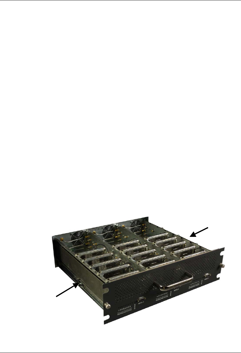
MC-Series System Installation & Testing
Final Checkout and Commissioning
RadioFrame Networks, Inc. 49
5 Using the breaker on the PDU and the power switch on the front of the EAS, turn up the EAS,
and then verify that it is operational before proceeding. For more information, refer to the
Motorola document Gen 3 Site Controller System Manual, 68P80801E30-O.
6 Using the breaker on the PDU and the power switch on the front of the secondary iSC-3, turn
up the secondary iSC-3, and verify that it is operational before proceeding. For more
information, refer to the Motorola document Gen 3 Site Controller System Manual,
68P80801E30-O.
7 Using the breaker on the PDU, turn up the CSU.
Configure the CSU according the manufacturer's documentation and Nextel standards.
8 Using the breaker on the PDU, turn up the BIC, AIC, and RBS 1, and then verify that all three
components are operational before proceeding.
Wait approximately 3 minutes for the following indicators:
• RBS: The STATUS LED for each group will light green in this order: A, B, and then C.
• RBS: The RADIOBLADE STATUS LEDs will light red and then green for each present
RadioBlade. If no RB is present, the LED will not light. To verify the contents of the RBS,
pull out the shelf (powering off is not required) and inspect the RadioBlades and their
respective status LEDs. Reinsert the RBS. To do this, press up on one side rail locking
arm and press down on the other side rail locking arm, and then push the unit into the
rack (see the following illustration).
• BIC CRIC and AIC CRIC: The POWER and STATUS LEDs will light red and then green.
All other BIC and AIC card LEDs will light green.
9 Using the breaker on the PDU, turn up RF Shelf 1, RF Shelf 2, and RF Shelf 3 and then
verify that each RF shelf is operational before proceeding.
The POWER and ALARM LEDs on the front of each RF shelf will light green.
locking arm
locking arm
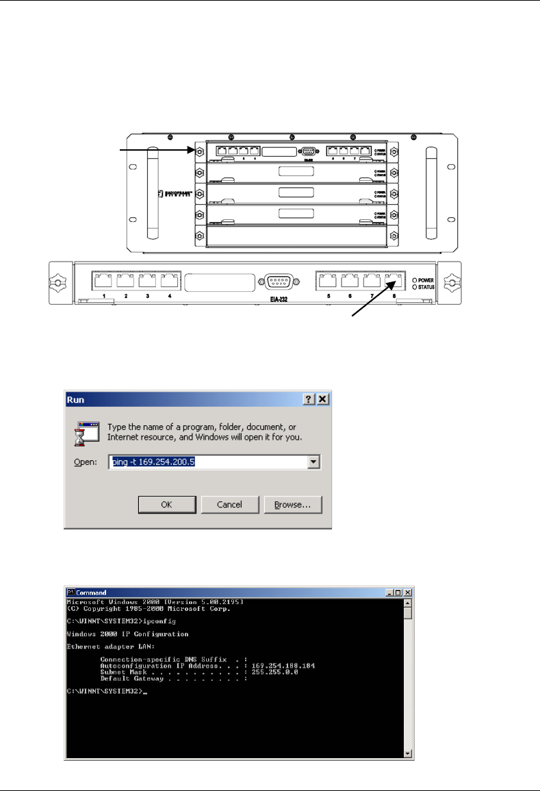
MC-Series System Installation & Testing
Final Checkout and Commissioning
50 RadioFrame Networks, Inc.
5.4 System Setup
1 Connect the laptop to port 8 of the BIC CRIC using an Ethernet (CAT5) cable.
2 From the laptop, ping the External IP Address of the MC-Series System (169.254.200.5).
If replies are returned from the ping, continue to Step 3. Otherwise, open a command prompt
window and enter: ipconfig. Verify that the IP address of the laptop is zero config.
laptop connection
BIC CRIC
BIC front

MC-Series System Installation & Testing
Final Checkout and Commissioning
RadioFrame Networks, Inc. 51
If it is not, at the command prompt enter the command setExtIpAddr:
-> setExtIpAddr
Current Ext IP Addr = 0.0.0.0
Set New External IP Addr
0-
Change the IP address by typing the following information shown in bold. Type the new
value, and press Return. The next line will appear. To leave a value as shown, press Return.
0- 169
0- 254
0- 200
0- 5
New Ext IP Addr = 169.254.200.5
Set New subnet Mask 0xFFFF0000 – 0xFFFF0000
New subnet Mask = 0xFFFF0000
Current Ext IP Addr = 0.0.0.0
Set New External Gateway Addr
Change the system as follows:
0 – 169
0 - 254
0 – 0
0 - 1
If the change is successful, the following information will appear:
New Ext Gateway Addr = 169.254.0.1
Unable to remove existing address
External IP Address = 169.254.200.5
value = 0 = 0x0
3 Start System Manager.
Launch a browser session and enter the MC-Series System IP address: http://169.254.200.5.
The System Manager Home page appears, which contains five tabs to select from:
• Home—displays a welcome banner and a link for setting up users and changing the
MC-Series System password.
• System Configuration—depicts the status of the BIC, AIC, and RBS.
• Alarms—displays alarm information.
• Performance Monitoring—displays real-time performance information.

MC-Series System Installation & Testing
Final Checkout and Commissioning
52 RadioFrame Networks, Inc.
• Diagnostics—provides tools for testing.
• Support—displays support information, including online help.
4 Log in to System Manager.
Select the System Configuration tab to display the login window. For User Name, type
Sysadmin (case sensitive). For Password, type Radioframe (case sensitive), and then
select OK. To change the password, refer to Appendix G: System Manager.
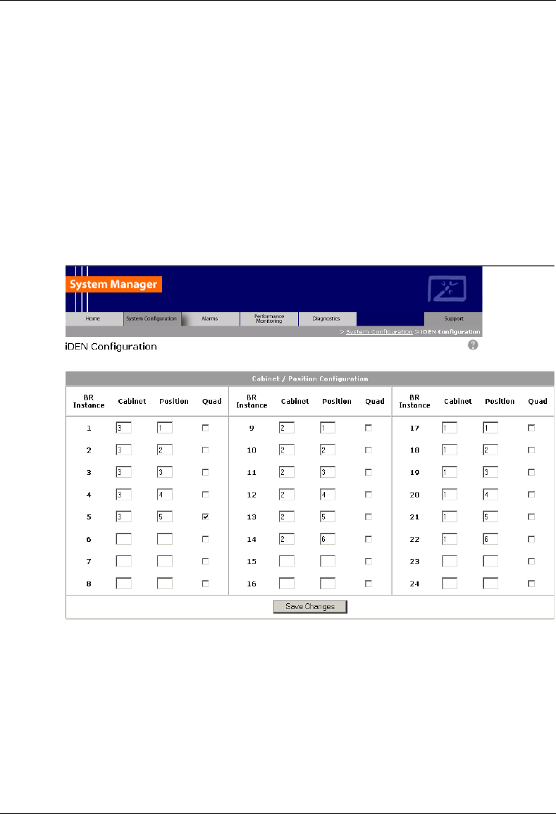
MC-Series System Installation & Testing
Final Checkout and Commissioning
RadioFrame Networks, Inc. 53
5 Select the iDEN Configuration link at the bottom of the System Configuration page, and
verify that the MC-Series System iDEN cabinet/position and quad BR configuration matches
the site datafill.
Change the BR cabinet and position on the iDEN Configuration page to match the site
datafill. Assign quad BRs as required by the site datafill (only one quad BR per group). For
more information, refer to section 3.4 iDEN Configuration.
NOTE: If the number of BR instances in the Site datafill is less than the number of BR
instances (cabinet and positions entered on the iDEN Configuration page) and the number of
RadioBlades installed in the group, the alarm EXT BR RESET will be triggered. RadioBlades
register and seek out a cabinet and position from System Manager; if one is not available,
they go into a standby mode and wait for an empty cabinet and position.
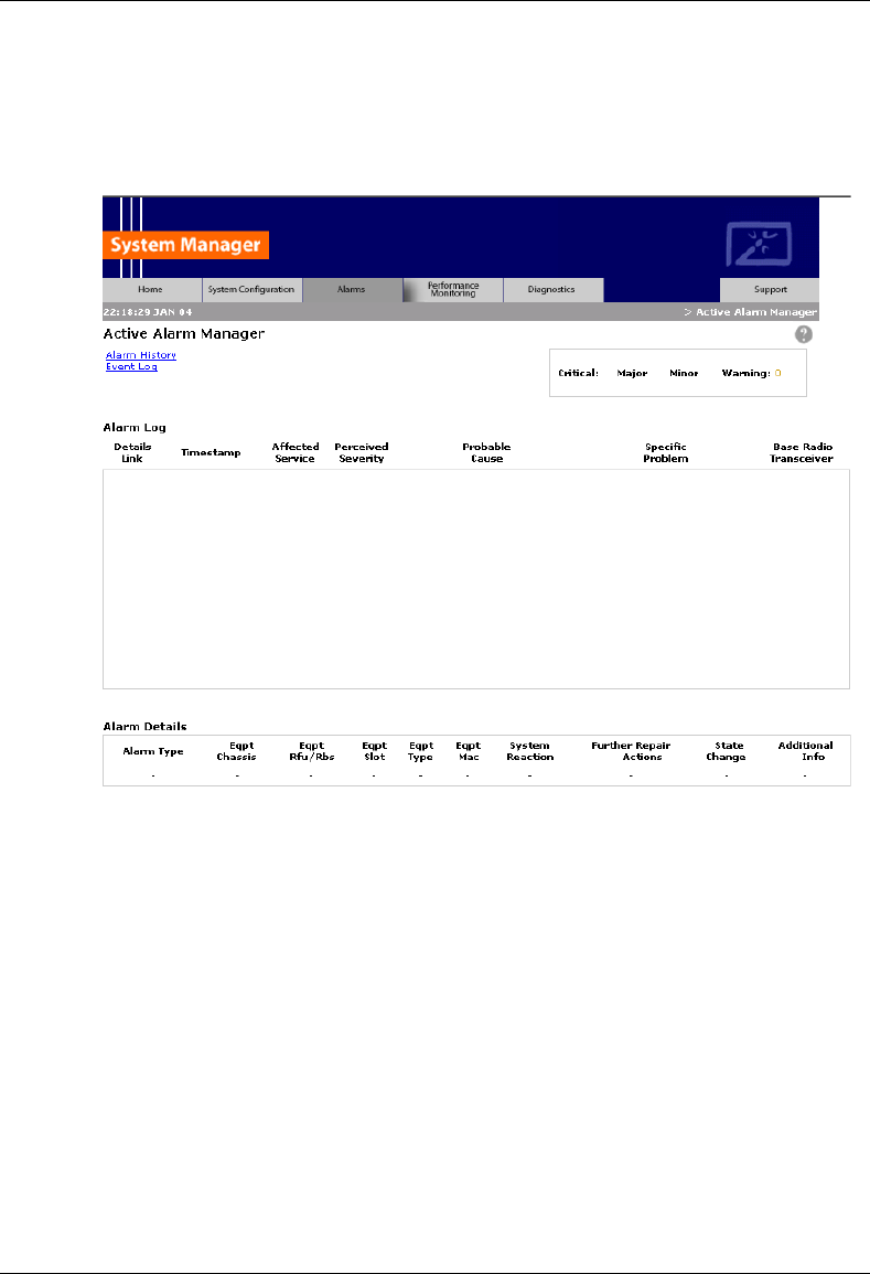
MC-Series System Installation & Testing
Final Checkout and Commissioning
54 RadioFrame Networks, Inc.
6 Select the Alarm tab and review the Active Alarm Manager for any active alarms.
If the Alarm Log is empty, the system may still be loading (it takes approximately 3 minutes
for the system startup to complete). Any RF shelf alarms remaining after startup may be
ignored for now. For more information, refer to section 7.2.2 System Manager Alarms.
7 Set the output power of the first BR according to site requirements.
Connect the General Dynamics R2660 Series Communication System Analyzer to the top of
the rack Tx OUT 1. Then set up the R2660 for iDEN Base mode. Enter the control channel
frequency for sector 1, and then measure the output power of that frequency.
For specifications, refer to section 2.5.9.2 Transmitter Performance Summary. The default is
+0 dBm per carrier, assuming that the datafill parameter defaultTxPower is set to 9.0. Either
adjust the datafill parameter (refer to section 6.3.6 defaultTxPower = 9.0.) or adjust the Tx
ATTENUATION knob on the front of the RF shelf. The outside knob adjusts in 10 dB
increments and the inside knob adjusts in 1 dB increments, up to 50 dB maximum.
NOTE: The default output power is displayed on the front of each RF shelf.
8 Measure the SQE and frequency error for the control channel to see if they are within
specifications.
9 Verify that all BRs have the same output power
000

MC-Series System Installation & Testing
Final Checkout and Commissioning
RadioFrame Networks, Inc. 55
For each channel, enter the frequency into the R2660 and verify that the SQE, frequency
error, and power level are all within specifications (refer to section 2.5.9.2 Transmitter
Performance Summary).
10 Repeat steps 6, 7 and 8 for each sector.
11 Review the Active Alarm Manager for any un-cleared alarms.
Refer to section 7.4 System Manager Alarms for more information.
5.5 Connect the MC-Series System to the Third-party RF Distribution
System
1 All MC-Series System elements can remain powered during removal of or connection to other
equipment.
2 Refer to the third-party RF Distribution System manufacturer's power procedures.
3 Measure the composite output from the Tx 1, Tx 2, and Tx 3 connectors at the top of the
cabinet using a digital RF power meter.
4 Use the variable Tx ATTENUATION knob on the front panel of each RF shelf to adjust the
composite output of each sector to accommodate the power budget of the DAS.
The outside knob adjusts in 10 dB increments, and the inside knob adjusts in 1 dB
increments, up to 50 dB maximum.
NOTE: The variable attenuators only impact the RF downlink. If large values of attenuation
are required, consider adding external attenuation to the uplink of the Rx port to maintain link
balance.
5 Make sure the Nextel-provided coax jumpers have been swept.
6 Connect the jumpers between Tx 1 and DAS RF IN, and then connect the jumpers between
Rx 1 and DAS RF OUT.
Connect the jumpers to the DAS commensurate with the sector coverage area and hub
locations per Nextel design.
7 Measure the output at the DAS remote unit(s) to verify power budget accuracy.
5.6 Functionality Test
RadioFrame Networks recommends that a certification process be completed to ensure proper
operational performance and to verify the integrity of the following services:
• Voice quality for 3:1 Interconnect Voice
• Voice quality for 6:1 Private Group Dispatch Voice
• Call setup reliability for 3:1 Interconnect Voice
• Call setup reliability for 6:1 Private and Group Dispatch Voice
• Call stability for all of the above voice services
• Connection quality, stability, delay and perceived throughput for the Packet Data service
• Connection setup reliability for Packet Data

MC-Series System Installation & Testing
Final Checkout and Commissioning
56 RadioFrame Networks, Inc.
• Idle SQE quality and variation
• Call up SQE quality and variation
• Short Message Service
• Handover and cell reselection
• Performance will also be validated by collecting at least one week of performance statistical
data
Refer to Appendix F Functionality Test Procedures for procedures to conduct functionality testing.
Note: MC-Series does not support 6:1 VSELP calls or Circuit Switched data.

MC-Series System Installation & Testing
Datafill Parameters & Optimization Procedures
RadioFrame Networks, Inc. 57
6 Datafill Parameters & Optimization Procedures
The MC-Series System is designed to be 100% compatible with the Motorola EBRC and QUAD
Base Radios. However, due to architecture differences between the two systems, not all datafill
parameters apply equally to the MC-Series System.
This section describes only those datafill parameters that need to be taken into consideration
when used with the MC-Series System. Any datafill parameter not described here can be
assumed to behave identically to the Motorola EBTS. This section includes:
1. Parameters that RFN does not support.
2. Parameters that have no effect on the RFN system.
3. Parameters that RFN supports, but which need to be setup differently than what is typically
setup for a Motorola Base Radio.
4. MIBs
5. Optimization procedures.
6.1 Unsupported Datafill Parameters
The following datafill parameters are currently not supported.
6.1.1 steThresholdMode
This parameter has three different purposes:
1. Setting to zero allows the EBTS to automatically determine the STE threshold based on
history of inbound transmissions.
2. Setting to maximum value of 250 essentially disables the use of STE filtering.
3. A manual override exists by setting the parameter in the range of 1 to 249. The default value
is set to 250.
The release notes indicate that this should only be used when sites are separated by more than
35 miles.
6.1.2 brPwrReducModeAcg
This parameter is used to enable/disable the Power Reduction feature on a per-BR basis. The
default value is set to 'ON' and it is on-line changeable.
The MC-Series System currently does not use this feature since the system uses considerably
less power than an EBRC.
6.1.3 brAddBuffering
This parameter adjusts the amount of buffering applied to all outbound voice packets prior to
sending to the ISC. The default setting is 0, which corresponds to 45 mSec of buffering.

MC-Series System Installation & Testing
Datafill Parameters & Optimization Procedures
58 RadioFrame Networks, Inc.
6.2 Parameters that Do Not Apply to the MC-Series System
The following parameters have no effect on the RFN system. There is no functional equivalent in
the MC-Series System and as such can be ignored.
6.2.1 combinerType
This parameter specifies the type of combiner used to connect the cells Base Radios to the
antenna. The options are hybrid and cavity. The MC-Series System is similar to a cavity type
combiner physically but it does not have the same frequency limitations as the cavity combiner
that this parameter is used for.
6.2.2 maxTx
No Information available. RFN does not use this value.
6.3 Recommended Datafill Parameters
The following parameters need to be set differently than what is currently set with Motorola BR.
These settings are not required, but recommended for best operation.
6.3.1 bcchInterleave = 4
This parameter defines how far apart the BCCH slots are spaced in the PCCH. RFN recommends
this value so as to maximize the number of outbound CCCH messages that are possible with the
system.
6.3.2 pcchInterleave = 6
This parameter defines how far apart the PCCH slots are spaced. This must be set to 6 if the
bcchInterleave is set to 4.
6.3.3 PCC = -65 (may change)
The power control constant is broadcast on the BCCH and is used by the MS to calculate a target
value for its transmit power. For Indoor, Pico and Micro-Cell applications this value will vary
depending upon the RF environment (i.e., if used outdoors the value will be quite different from
an indoor scenario). The default value should be calculated in accordance with Motorola
guidance detailed in the Datafill Parameter Guide. It should be noted that in cases in which the
Mobile subscribers are near the antenna source (downlink limited), the handsets could transmit at
a much lower level than is the case with a Macro site. Lowering this parameter forces the mobile
to operate at fairly low TX level thus conserving battery life. In cases where the MC-Series is
connected to a fiber DAS the gains and losses of the paths should be taken into consideration.
Additionally the level of uplink interference should be considered when determining this value.

MC-Series System Installation & Testing
Datafill Parameters & Optimization Procedures
RadioFrame Networks, Inc. 59
6.3.4 Pto = 20 (transmit power)
The Cells outbound transmit power referenced at the output of the RF Distribution System
Antenna Port. It is used as a reference point value when computing the link budget of the system.
Although the actual Pto of the MC-Series System is less than 20, RFN recommends this value
since it is the minimum settable value for this parameter bringing it as close as possible to the
actual value.
6.3.5 rxTxGain = 10
This parameter is the difference in gain between the receiver and transmit antenna paths
expressed in dB. The MC-Series System does not use this parameter directly, and the true
rxTxGain is actually 0dB. RFN recommends this setting to help offset the Pto value when used in
making handover calculations.
6.3.6 defaultTxPower = 9.0 (refer to release notes for range information)
This is the average output power of the PA, measured at the RF connector of the BR. For the
MC-Series System, this parameter can be used to adjust the output power of the system. The
MC-Series System has a different range of output levels than a standard Motorola EBTS, and as
such, these values will map to a different set of actual Tx output power levels. This value can be
set from 1.3 (watts) to 70 (watts), however, Quad BRs configured for 4 channels cannot exceed
10.5 (watts). Therefore, the recommended range is limited to 8.4 through 9.5, which allows a
power adjustment range of 11.5 dB.
The transmit power out at the top of the rack (TOR) is dependent on the site datafill as well as the
attenuator settings on the RF Shelves. Each RF Shelf has a default attenuator setting, calibrated
at the time of manufacture and labeled on the front of the RF Shelf, that provides 0 dBm TOR
output power per carrier when the datafill defaultTxPower value is set to 9.0.
The defaultTxPower parameter can take on values between 5 and 75. However, only a range of
these values will result in an actual power output change in the MC-Series System. The following
table summarizes the mapping between the defaultTxPower value and the TOR transmit power
per carrier, for a given RF Shelf attenuator setting.
Table 3 TOR output power is based on the DefaultTxPower and the Attenuator setting
DefaultTxPower Setting
(datafill parameter)
Tx Attenuator Setting (dB) Top of the Rack (TOR)
Output Power (dBm)
TxAtten +5 9.5 and higher
TxAtten - 5 +10
TxAtten +0 9.0 (default)
TxAtten - 10 +10
TxAtten -1 8.9
TxAtten - 10 +9
TxAtten -6 8.4 and lower
TxAtten - 10 +4

MC-Series System Installation & Testing
Datafill Parameters & Optimization Procedures
60 RadioFrame Networks, Inc.
6.3.7 cellPtiMax = 5 (B-Series)
The maximum power an MS is allowed to transmit in a particular cell. For Pico and Micro-Cell
applications in which the mobile subscribers are most likely near the antenna source, the MS can
transmit at a relatively low level. To conserve battery life, we recommend the lowest power
setting.
6.3.8 handoverClass
This parameter indicates for each neighbor cell, whether the neighbor cell should be considered
for handover. RFN recommends the following values for systems that are used within a building.
These values maximize the likelihood that the call will stay on the in-building system, thus
offloading the subscribers from any local macro cell.
a. macro neighbor in RFN list = 1
b. RFN on macro neighbor list = 3
c. RFN on RFN neighbor list = 2
It is also recommended that the RFN sectors isolated to upper floors of buildings do not contain
macros in their neighbor list.
6.3.9 reconnectionClass
Indicates for each neighbor cell, whether the cell should be considered for reconnection.
Reconnection is mobility management during a dispatch call. RFN recommends the following
values for systems that are used within a building. These values maximize the likelihood that the
call will stay on the in-building system, thus off-loading the subscribers from any local macro cell.
a. macro neighbor in RFN list = 1
b. RFN on macro neighbor list = 3
c. RFN on RFN neighbor list = 2
6.3.10 hdvrCINROutboundHysteresis = 8
The outbound C/I+N hysteresis, in dB, for evaluating handover candidates. This is a typical value.
6.3.11 hdvrCINRInboundThreshold = 19
The inbound C/I+N threshold, in dB, for handover and evaluating handover candidates. RFN
recommends this value for increasing the likelihood of the call staying within the RFN cell.
6.3.12 hdvrCINRInboundHysteresis = 8
The inbound C/I+N hysteresis, in dB, for evaluating handover candidates. This is a typical value.

MC-Series System Installation & Testing
Datafill Parameters & Optimization Procedures
RadioFrame Networks, Inc. 61
6.3.13 hdvrCINROutboundThreshold = 6
The outbound C/I+N threshold on the serving cell for handover and for evaluating handover
candidates. RFN recommend this value for increasing the likelihood of the call staying within the
RFN cell.
6.3.14 brBrBand = 2 (800 MHz)
Specifies the operating band of the System. RFN currently supports the 800Mhz band.
6.4 MIB Disparity
The following SNMP MIB (Management Information Base) statistics variables return incorrect
information. The variables are set correctly except where noted.
• cabinetId and postionId
• fneFailThreshold
• maxTxWindow
• assignedChannelBr
• addBufferingBr (not used)
• ccExtension
• pwrReducModeBr (not used)
• numPrapCollision
• carrierIndex
• dcapCount
• sdgcPagingRequestTx
• sdgcGrantTx
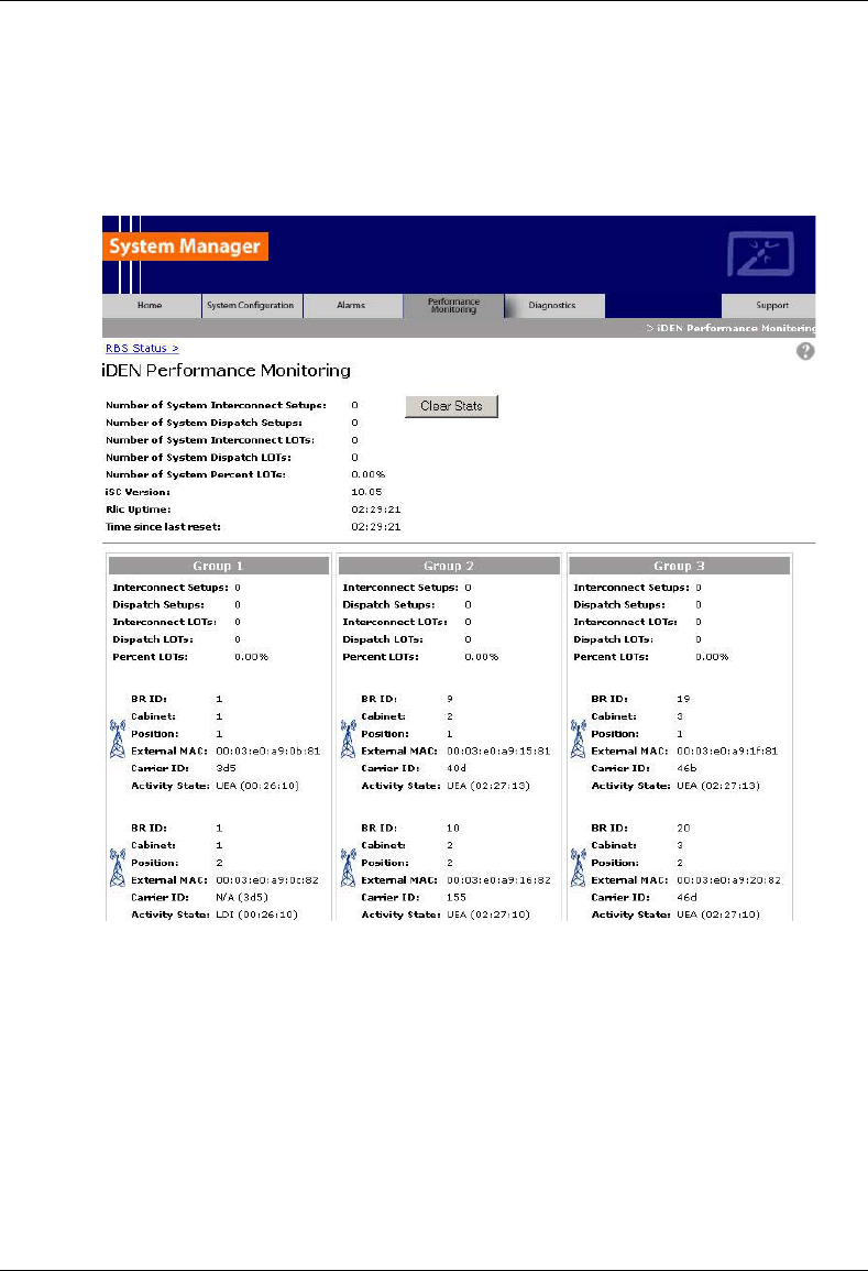
MC-Series System Installation & Testing
Datafill Parameters & Optimization Procedures
62 RadioFrame Networks, Inc.
6.5 Local Performance Monitoring
1 In System Manager, select the Performance Monitoring tab.
2 Select a BR icon to display the Base Radio Performance Statistics page.
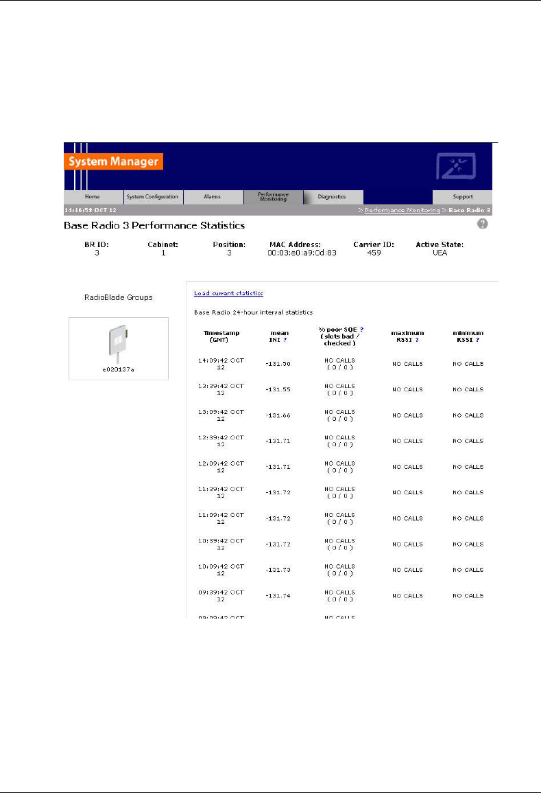
MC-Series System Installation & Testing
Datafill Parameters & Optimization Procedures
RadioFrame Networks, Inc. 63
3 Verify that the mean INI is within normal range (-120 to –130 dBm).
4 Verify that the % poor SQE does not exceed 2% on a substantial number of packets (i.e.,
greater than 10,000 packets).
5 Repeat steps 2 through 4 for each BR in the system.

MC-Series System Installation & Testing
Scheduled and Unscheduled Maintenance
64 RadioFrame Networks, Inc.
7 Scheduled and Unscheduled Maintenance
A report of the MC-Series System should be maintained and left on site. This report will provide
metrics for possible concerns with individual components and/or the entire system. It is important
that the technician performing the checks understand the equipment theory and operation.
Review the documentation (references) prior to verification and performing service.
For non-RFN hardware, refer to the equipment manufacturer’s documentation for maintenance
information and procedures. For the iSC-3s and the EAS, refer to the Gen 3 Site Controller
System Manual, Motorola, 68P80801E30-O. For the CSU, refer to the manufacturer's
documentation for preventive maintenance information.
7.1 Annual Maintenance
Conduct the following annual maintenance:
• Visually inspect all equipment in the MC-Series System cabinet for loose or foreign items and
for visible damage.
• Verify all site configuration cabling is correct (refer to Appendix C and D Cabling Diagrams)
• Conduct the BER test on each RadioBlade transceiver (refer to Appendix H BER Test
Procedure).
• Conduct the TOR Tx measurement (RF output measurement) on each transmitter (refer to
section 7.10)
7.2 Troubleshooting Guidelines
Technicians should conduct the following troubleshooting steps in order:
1 Visually inspect for fault indication (LEDs). Refer to section 7.3.
2 Inspect the Alarm Manager, and follow alarm resolution procedures. Refer to sections 7.4,
7.5, and 7.6.
3 Contact the RFN Technical Assistance Center at: (800) 328-0847. Also, refer to section 1.4
Repair and Technical Support
4 Complete and save the serial log upload of cards. Refer to section 7.7
5 Refer to section 7.9, Field Replaceable Units (FRU) as required.
7.3 Fault Indications
This section provides fault indications for the following RadioFrame Networks components only:
BIC, AIC, RBS, and RF Shelf. For all non-RFN equipment, refer to Nextel’s or the manufacturer’s
documentation.

MC-Series System Installation & Testing
Scheduled and Unscheduled Maintenance
RadioFrame Networks, Inc. 65
7.3.1 BIC
LED Indication Condition Corrective action
not lit no power to BIC Verify that BIC circuit breaker on PDU is
ON.
Check power connection to PDU.
Measure power input, and compare with
tolerances listed in section 2
“Specifications”.
Verify that the power source is
operational.
Contact the TAC: (800) 328-0847
green normal condition none
not lit card(s) not receiving power Verify power to BIC (see “POWER”
above)
bootup not complete Allow three minutes (approx.) for bootup
to complete.
red
CRIC
only
timing not synchronized Verify that the GPS LED on iSC-3 is
green.
Verify that the cable is connected from
BIC ERTM port 5MHz/1PPS IN to iSC-3
port 5MHz/1PPS.
Contact the TAC: (800) 328-0847
STATUS
red
any card
PLLs are not locked Verify that the STATUS LED on the BIC
CRIC is green
Check the Alarm Manager for PLL LOCK
alarm; wait 3 minutes for PLLs to lock; if
they do not:
Verify integrity of Ethernet connection
between BIC and AIC.
Contact the TAC: (800) 328-0847
7.3.2 AIC
LED Indication Condition Corrective action
POWER green normal condition none

MC-Series System Installation & Testing
Scheduled and Unscheduled Maintenance
66 RadioFrame Networks, Inc.
LED Indication Condition Corrective action
not lit no power to AIC Verify that AIC circuit breaker on PDU is
ON.
Check power connection to PDU.
Measure power input, and compare with
tolerances listed in section 2
“Specifications”.
Verify that the power source is
operational.
Contact the TAC: (800) 328-0847
green normal condition none
not lit card(s) not receiving power Verify power to AIC (see “POWER”
above)
STATUS
red PLLs are not locked Verify that the STATUS LED on the BIC
CRIC is green
Check the Alarm Manager for PLL LOCK
alarm; wait 3 minutes for PLLs to lock; if
they do not:
Verify integrity of Ethernet connection
between BIC and AIC.
Contact the TAC: (800) 328-0847
7.3.3 RBS
LED Indication Condition Corrective action
green normal condition none STATUS
not lit no power to RBS Verify that RBS circuit breaker on
PDU is ON.
Check power connection to PDU.
Measure power input, and compare
with tolerances listed in section 2
“Specifications”.
Verify that the power source is
operational.
Contact the TAC: (800) 328-0847

MC-Series System Installation & Testing
Scheduled and Unscheduled Maintenance
RadioFrame Networks, Inc. 67
LED Indication Condition Corrective action
red timing is not synchronized
to the group (A, B, or C)
Board unable to boot
Power cycle the RBS using the
circuit breaker on the PDU.
Contact the TAC: (800) 328-0847
green RB present and operational none
RB not present none
not lit
RB present Reseat RB.
RADIOBLADE
STATUS
red RB is in error state Reseat RB.
If still red, replace RB.
7.3.4 RF Shelf
LED Indication Condition Corrective action
green normal condition none POWER
not lit no power to RF shelf Verify that RF circuit breaker on PDU is
ON.
Check power connection to PDU.
Measure power input, and compare with
tolerances listed in section 2
“Specifications”.
Verify that the power source is
operational.
Contact the TAC: (800) 328-0847
green normal condition none
not lit not receiving power Verify power to RF Shelf (see “POWER”
above).
ALARM
red alarm condition Check the Alarm Manager for:
RF SHELF MINOR, replace fan.
RF SHELF MAJOR, replace RF shelf.
Contact the TAC: (800) 328-0847

MC-Series System Installation & Testing
Scheduled and Unscheduled Maintenance
68 RadioFrame Networks, Inc.
7.4 System Manager Alarms
The MC-Series System provides fault alarming and isolation within System Manager for individual
components, which consists of detecting catastrophic faults that prevent a component from
responding to a periodic “ping”. Depending on the severity, alarms are sent to the OMC via the
iSC-3. All alarms passed to the OMC use the Nextel Alarm Code 35009, which uses the event
description “Unable to key BR”.
This section describes:
• How to view alarms in System Manager,
• OMC alarm code and severity levels,
• System Manager alarms sent to the OMC, and
• System Manager alarms and resolution procedures
7.4.1 Viewing System Manager Alarms
1 Select the Alarms tab in System Manager to display the Active Alarm Manager.
The Alarm Log displays active (un-cleared) alarms listed by date and time, and the Alarm
Details window displays information about a single selected alarm (see the following
illustration). A summary at the top of the page lists the current number of Critical, Major,
Minor, and Warning alarms. Alarms that are no longer active are moved to the Alarm
History Manager.
NOTE: If the Alarms page is empty, System Manager is still loading the page.
Non-alarm events are displayed in the Events Log. The initial Events Log lists all the alarms
generated by RFS components. You can view a smaller list by selecting one of the Show
links at the bottom of the page. Clicking the first link with a value of 20 in the box displays the
first 20 alarms. You can enter any number in the field
Alarms Log Field Description
Details Displays details of the alarm in the Alarm Details window
Timestamp Date and time alarm occurred (in Greenwich meantime-GMT)
Affected Service iden: iDEN software only
asp: platform software only
rfn: All system software is affected (platform, iDEN)
Perceived Severity cleared: A ‘set’ alarm has been cleared and moved to Alarm History
critical : Service affecting failure; requires immediate attention
major : Service affecting degradation; requires urgent attention
minor: Non-service affecting condition; requires scheduled attention
warning: Potential condition that may lead to a more serious alarm
Probable Cause Describes what might have caused the alarm
Specific Problem Describes more the problem more specifically
Base RadioTransceiver BR ID (1 through 32) or n/a for not applicable
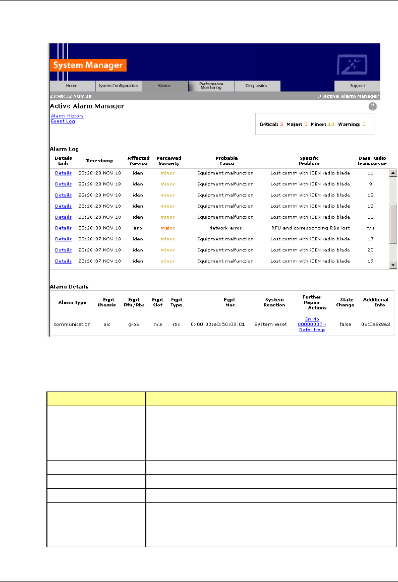
MC-Series System Installation & Testing
Scheduled and Unscheduled Maintenance
RadioFrame Networks, Inc. 69
2 To view details about a specific alarm, select the Details link next to the alarm. The Alarm
Details window displays the following information:
Alarm Details Field Description
Alarm Type Communication : failure to convey information
Quality of service : signal degradation
Processing error: software processing fault
Equipment: equipment fault
Environmental: condition with the equipment enclosure
Eqpt Chassis Affected chassis: bic or aic
Eqpt Rfu/Rbs Affected RBS group: grp A, grp B, or grp C
Eqpt Slot Affected chassis slot: BIC (1-5), AIC (1-5), or RBS (1-24)
Eqpt Type rfn: unknown
rlic: BIC CRIC
bpc: BPC or BPC+SPAM
ric: AIC CRIC

MC-Series System Installation & Testing
Scheduled and Unscheduled Maintenance
70 RadioFrame Networks, Inc.
Alarm Details Field Description
rbs: RBS
idenrb: RadioBlade
Eqpt Mac MAC address of the affected component
System Reaction The action taken by the system as a result of the alarm.
Further Repair Actions Corrective action that should be taken as a result of the alarm.
State Change Not currently used (displays ‘false’ by default)
Additional Info Miscellaneous 32-bit field
7.4.2 OMC Alarm Code
All RFS MC-Series alarms sent to the OMC use the Nextel Alarm Code 35009 (see the following
table). The Event Description for this alarm is 'Unable to key BR'.
Event Description
Nextel Alarm Code 35009
Event Type CntrlBrd
Alarm Type Equipment Failure
Actionable Yes
Severity Minor, Major or Critical
Bounce Threshold (x) 3
Bounce Threshold Minutes 30
Duration Threshold 10
Related Alarms None
R & C RC
Outage Y/N S1_El CY
Event Description Unable to key BR
Advisor Site Service call
Comments None
Alert Names BREFCTLBD35009
Last updated 8/3/2001
Revision
Change Notes 8/3/2001: per new EBTS rules baseline.
Changed severity and threshold from GR1 to:
Severity=minor
BounceThreshold=3
Bounce Threshold Minutes=30

MC-Series System Installation & Testing
Scheduled and Unscheduled Maintenance
RadioFrame Networks, Inc. 71
Event Description
Duration Threshold=10
Action Create trouble ticket.
Contact Field Technician.
TS/BR
7.4.3 System Manager Alarms Sent to the OMC
The table below lists System Manager alarms that are sent to the OMC, the OMC alarm
message, and the severity of the alarm.
OMC Alarm System Manager Alarm Severity
BOARD DISABLED 1.2.3.4 PEER LOSS CRITICAL
COVERAGE HOLE COVERAGE HOLE MAJOR
EXCESS RESETS EXCESS RESETS CRITICAL
ISC VER MISMATCH ISC VER MISMATCH MAJOR
NO SPAM IN APC APC NO SPAM CRITICAL
RADIO BLADE LOST IDENRB LOSS MINOR
RB ASSOC ERROR RB ASSOC ERROR MAJOR
RF SHELF 1, 2, or 3 RF SHELF MINOR MINOR
STARTUP FAIL STARTUP FAIL MINOR
TEMPERATURE CRITICAL TEMPERATURE CRITICAL CRITICAL
TEMPERATURE MAJOR TEMPERATURE MAJOR MAJOR
7.4.4 System Manager Alarms
This section lists MC-Series System alarms numerically by alarm ID (0x01, 0x02, etc.) with the
alarm description as the title of the subsection. These alarms are based on the X.733 conventions
for telecommunications equipment. For more information about field descriptions, refer to section
7.4.1 Viewing System Manager Alarms.
The service can be (asp – platform, iden- iden application, wlan – wireless application). The
cause refers to the x.733 cause type. System reaction describes the action taken by the system
as a result of this alarm and repair actions provides details on what corrective action should be
taken as a result of this alarm.
The Alarm details on the active alarm manager page of the system manager will provide
additional information with respect to the board, slot number, mac address, equipment type etc. is
available in System Manager.

MC-Series System Installation & Testing
Scheduled and Unscheduled Maintenance
72 RadioFrame Networks, Inc.
7.4.4.1 Alarm Overflow error
ID: 0001
Service: asp
Severity minor
Cause: Underlying Resource Unavailable
System Reaction: Alarms Were Discarded
Additional Info: None
Repair Action: This condition results from an error in the alarm manager handler in which there
is no longer enough space for the alarms. If this situation happens, most likely there is a
catastrophic failure that needs to be addressed first. Review previous alarms for root cause.
Note: This alarm does not have a clear.
7.4.4.2 Target Initialization Error
ID: 0002
Service: asp
Severity critical
Cause: Underlying Resource Unavailable
System Reaction: Equipment goes in Disabled State
Additional Info: None
Repair Action: The system was unable to load the software properly for the following reasons.
A) Proper SW version has not been loaded onto the board. Check SW revision and/or re-load
SW.
B) Reset Board
C) Board loader failing. Replace Board
7.4.4.3 Task Abnormally Terminated
ID: 0003
Service: asp
Severity major
Cause: S/W Program Abnormally Terminated
System Reaction: System Reset including RLIC
Additional Info: First 4 ASCII Text characters of the task that suspended
Repair Action: System should recover on its own. However, this alarm should be reported to
RFN for further investigation. Check corresponding board for any connection problems.
Note: This alarm does not have a clear.

MC-Series System Installation & Testing
Scheduled and Unscheduled Maintenance
RadioFrame Networks, Inc. 73
7.4.4.4 Task Abnormally Terminated
ID: 0004
Service: asp
Severity: major
Cause: S/W Program Abnormally Terminated
System Reaction: System Reset except for RLIC
Additional Info: First 4 ASCII Text characters of the task that suspended
Repair Action: System should recover on its own. However, this alarm should be reported to
RFN for further investigation. Check corresponding board for any connection problems.
7.4.4.5 Spinning task starving system
ID: 0005
Service: asp
Severity: major
Cause: Application Subsystem Failure
System Reaction: System Reset
Additional Info: None
Repair Action: Check corresponding board for any flash corruption. System should recover on
its own. However, this alarm should be reported to RFN for further investigation. Collect target
serial logs.
7.4.4.6 Lost communication with target
ID: 0007
Service: asp
Severity: critical
Cause: Remote Node Transmission Error
System Reaction: System Reset
Additional Info: Peer IP Address
Repair Action: This is a result of lost communication with a target board. Check the
corresponding board for improper insertion, faulty cables, improperly inserted cable.
7.4.4.7 5 MHz clock signal not present
ID: 0008
Service: asp
Severity: critical
Cause: Loss of Signal

MC-Series System Installation & Testing
Scheduled and Unscheduled Maintenance
74 RadioFrame Networks, Inc.
System Reaction: No Action Taken
Additional Info: None
Repair Action: This is a result of lost clock signal from the ISC if it is an RLIC or a timing error if
it is a RIC. If the alarm came from the RLIC, check the ISC clock connection. If the alarm came
from a RIC, check the Ethernet cabling between RIC and RLIC. Check GPS light on ISC.
If clear follows soon after set (generally 6 seconds)
- if not too frequent ignore it. Could be an intermittent network error.
- If frequent or periodic, check for bad cable connections. Try a different Ethernet port.
7.4.4.8 Phase lock loops not locked
ID: 0009
Service: asp
Severity: critical
Cause: Timing Problem
System Reaction: All BR’s will lock. Trap sent to ISC.
Additional Info: None
Repair Action: If it is the RLIC check for noisy or missing ISC clock. This alarm will always be
generated as the system is coming up. If there is no clear after 20 minutes, replace board. Check
GPS light on ISC.
7.4.4.9 DSPs failed to load
ID: 0010
Service: asp
Severity: critical
Cause: Equipment Malfunction
System Reaction: No Action taken
Additional Info: None
Repair Action: Verify that the DSP SW loads exist on the system. Try re-downloading the
software. Reseat SPAM. Replace Board.
Note: This alarm does not clear.
7.4.4.10 DSP host port interface failed
ID: 0011
Service: asp
Severity: major
Cause: Equipment Malfunction

MC-Series System Installation & Testing
Scheduled and Unscheduled Maintenance
RadioFrame Networks, Inc. 75
System Reaction: If errors exceed threshold, DSP is reset.
Additional Info: DSP Core ( 1 – 12 )
Repair Action: Can ignore if infrequent. Reseat SPAM in BPC (APC). Replace SPAM or
Replace BPC (APC).
7.4.4.11 Too many resets within window
ID: 0012
Service: asp
Severity: major
Cause: Application Subsystem Failure
System Reaction: All BRs locked, system held in a disabled state
Additional Info: None
Repair Action: This is a result of more than 4 system resets within a 30 minute period.
Investigate cause of system resets from previous alarms. Requires a commanded reset to
restore.
Note: This alarm does not clear.
7.4.4.12 System Reset
ID: 0013
Service: asp
Severity: warning
Cause: Application Subsystem Failure
System Reaction: System Reset
Additional Info: None
Repair Action: This is the result of an alarm that causes a system reset. The purpose of this
alarm is to create a placeholder in the alarm log to indicate that a system reset had taken place.
Investigate root cause from previous alarms.
7.4.4.13 1 of 2 cooling fans has failed
ID: 0014
Service: asp
Severity: minor
Cause: Equipment Malfunction
System Reaction: No Action Taken
Additional Info: Fan number ( 1 or 2 )
Repair Action: Inspect chassis fans for proper operation.

MC-Series System Installation & Testing
Scheduled and Unscheduled Maintenance
76 RadioFrame Networks, Inc.
7.4.4.14 Temperature problem detected
ID: 0015
Service: asp
Severity: warning
Cause: Temperature Unacceptable (Warning)
System Reaction: None
Additional Info: None
Repair Action: Alarm will be generated if temperature exceeds a set threshold and will clear
below a set threshold. Inspect Unit environment.
7.4.4.15 Temperature problem detected
ID: 0017
Service: asp
Severity: major
Cause: Temperature Unacceptable (Major)
System Reaction: None
Additional Info: None
Repair Action: Alarm will be generated if temperature exceeds 49 C and will clear below 46 C.
Inspect Unit environment.
7.4.4.16 Temperature problem detected
ID: 0018
Service: asp
Severity: critical
Cause: Temperature Unacceptable (Critical)
System Reaction: System Reset
Additional Info: None
Repair Action: Alarm will be generated if temperature exceeds 52 C and will clear below 49 C.
Inspect Unit environment.
7.4.4.17 Target booted wrong partition
ID: 0019
Service: asp
Severity: warning
Cause: Corrupt Data

MC-Series System Installation & Testing
Scheduled and Unscheduled Maintenance
RadioFrame Networks, Inc. 77
System Reaction: No Action Taken
Additional Info: None
Repair Action: Check for Correct Version of SW on each partition. Re-download software.
7.4.4.18 Application version mismatch
ID: 0020
Service: asp
Severity: warning
Cause: Configuration Customization Error
System Reaction: No Action Taken
Additional Info: None
Repair Action: Check for correct version of SW on each partition.
7.4.4.19 No SPAM detected in APC
ID: 0023
Service: asp
Severity: major
Cause: Equipment Malfunction
System Reaction: BR will not be allowed to go UEA
Additional Info: None
Repair Action: Verify that the BPC (APC) has a SPAM and that it is the correct capacity. Reseat
the SPAM or Replace. Replace BPC (APC).
7.4.4.20 Unknown device in RFU slot
ID: 0027
Service: asp
Severity: minor
Cause: Configuration Customization Error
System Reaction: No Action Taken
Additional Info: RFU/RBS group slot number
Repair Action: Inspect the RBS/RFU for unusual hardware. Reseat card in question otherwise
replace card in RBS/RFU.
7.4.4.21 User invoked system reset
ID: 0028

MC-Series System Installation & Testing
Scheduled and Unscheduled Maintenance
78 RadioFrame Networks, Inc.
Service: asp
Severity: warning
Cause: User Intervention
System Reaction: System Reset
Additional Info: None
Repair Action: System was reset from System Manager, no action necessary. This alarm is
used as a place holder in the history alarm log.
Note: This alarm has no clear.
7.4.4.22 User invoked alarm history clr
ID: 0029
Service: asp
Severity: warning
Cause: User Intervention
System Reaction: Alarm history log cleared
Additional Info: None
Repair Action: Alarm history log was cleared from System Manager, no action necessary. This
alarm is a used as a place holder in the history alarm log.
Note: There will be no OMC alarm sent for this.
7.4.4.23 Out of assignable IP addresses
ID: 0033
Service: asp
Severity: major
Cause: Underlying Resource Unavailable
System Reaction: No Action Taken
Additional Info: None
Repair Action: Internal error most likely due to improper system configuration. Confirm proper
setup of each component. Report Error to RFN.
7.4.4.24 Software Baselining Server Problem
ID: 0037
Service: asp
Severity: warning
Cause: Underlying Resource Unavailable
System Reaction: No action taken

MC-Series System Installation & Testing
Scheduled and Unscheduled Maintenance
RadioFrame Networks, Inc. 79
Additional Info: None
Repair Action: Re-download the software load lineup to the RLIC and reset system. This alarm
should only occur after a software download and a reset to that partition.
7.4.4.25 RF Shelf External Alarm Major
ID: 0038
Service: asp
Severity: Major
Cause: Equipment Malfunction
System Reaction: No action taken
Additional Info: RBS Group Number
Repair Action: Replace the RF shelf reporting the alarm. Connect serially to the RF shelf to
further isolate the specific failure.
7.4.4.26 RF Shelf External Alarm Minor
ID: 0039
Service: asp
Severity: Minor
Cause: Equipment Malfunction
System Reaction: No action taken
Additional Info: RBS Group number
Repair Action: Replace the defective fan on the back of the RF shelf unit.
7.4.4.27 LAPD connection to ISC failed
ID: 4097
Service: iden
Severity: critical
Cause: Local Node Transmission Error
System Reaction: BR Disabled
Additional Info: minor state 1..15
Repair Action: Check connection to ISC. Check ISC status. Can also be caused by another
RFN system sharing the same connection to the ISC if its BR’s are configured the same.
7.4.4.28 Lost comm. With iDEN RadioBlade
ID: 4098

MC-Series System Installation & Testing
Scheduled and Unscheduled Maintenance
80 RadioFrame Networks, Inc.
Service: iden
Severity: minor
Cause: Equipment Malfunction
System Reaction: RB moved to standby state. BR may be Disabled.
Additional Info: RB Index
Repair Action: This happens when the system is no longer able to communicate with the Radio
Blade. Reseat RadioBlade, Move to different slot, check RBS/AIC connection. Replace
RadioBlade.
7.4.4.29 APC failed to sync with NPC
ID: 4100
Service: iden
Severity: critical
Cause: Equipment Malfunction
System Reaction: System Reset
Additional Info: None
Repair Action: If alarm does not clear, check cabling between AIC and BIC. Replace BPC. This
could be a result of a timing problem on the CRIC or backplane as well.
7.4.4.30 DSP Tx Packet Failed
ID: 4101
Service: iden
Severity: critical
Cause: Loss of Signal
System Reaction: System Reset
Additional Info: dsp index 1..16
Repair Action: Previously called DSP 1180 FLOODING. If happens at startup then check the RB
and try power cycling RB or RFU. Ignore if happens infrequently. If alarm does not clear or alarm
happens frequently,
- Reseat SPAM.
- Replace BPC
7.4.4.31 DSP Rx Packet Failed
ID: 4102
Service: iden
Severity: major

MC-Series System Installation & Testing
Scheduled and Unscheduled Maintenance
RadioFrame Networks, Inc. 81
Cause: Loss of Signal
System Reaction: Reset RadioBlade
Additional Info: Radio Blade index
Repair Action: This problem is a result of the DSP not receiving packets from the RadioBlade. If
this alarm does not clear itself or is happening frequently then replace the RadioBlade. If the
problem still persists, replace SPAM and/or APC.
7.4.4.32 RB VGA Error
ID: 4103
Service: iden
Severity: minor
Cause: Degraded Signal
System Reaction: Reset RadioBlade
Additional Info: Radio Blade index
Repair Action: This is the result of the system detecting a RadioBlade reporting erroneous vga
values. Replace RadioBlade.
7.4.4.33 Carrier Assignment failure
ID: 4104
Service: iden
Severity: major
Cause: Call Establishment Error
System Reaction: BR Disabled
Additional Info: Carrier Frequency
Repair Action: This is a result of an unusually high number of assignment failures from a
particular Mobile on a particular BR. This is an indication of an RF problem with one of the
RadioBlades. The debug field is the frequency of the carrier that would not allow assignment too.
The event log will contain the RadioBlade index of the PCCH. This RadioBlade index will indicate
the RBS, the frequency will be the carrier in that RBS. Replace the RadioBlade.
Note: This alarm does not have a clear
7.4.4.34 DSP reset threshold exceeded
ID: 4105
Service: iden
Severity: critical
Cause: Threshold Crossed
System Reaction: System Reset

MC-Series System Installation & Testing
Scheduled and Unscheduled Maintenance
82 RadioFrame Networks, Inc.
Additional Info: dspId or 0xff for hpi error
Repair Action: Check preceding alarms as to the cause of the SPAM reset. Reseat SPAM, if
problem persists, replace BPC.
7.4.4.35 Network memory shortage
ID: 4106
Service: iden
Severity: critical
Cause: Out of Memory
System Reaction: System Reset
Additional Info: cluster level
Repair Action: Internal problem with the network memory pool. Replace BPC.
7.4.4.36 Invalid RB Slot
ID: 4108
Service: iden
Severity: minor
Cause: Equipment Malfunction
System Reaction: Reset RadioBlade
Additional Info: None
Repair Action: Reseat RadioBlade. If problem still persists, replace RadioBlade or move to
another slot. If problem still persists, replace RBS.
7.4.4.37 DSP Tx null PDU
ID: 4110
Service: iden
Severity: minor
Cause: Loss of Signal
System Reaction: SPAM Reset
Additional Info: APC Mac address
Repair Action: This is a result of the DSP sending incorrect data to the RadioBlade. Ignore if
happening infrequently. Check for intermittent cable connections. Possibly a result of timing
problems on the NPC.
7.4.4.38 Interference/Calibration
ID: 4111

MC-Series System Installation & Testing
Scheduled and Unscheduled Maintenance
RadioFrame Networks, Inc. 83
Service: iden
Severity: minor
Cause: Degraded Signal
System Reaction: Reset RadioBlade
Additional Info: Radio Blade Index
Repair Action: This is a result of either an interference source or the RadioBlade is going out of
Calibration. Lock or swap RadioBlades with that carrier. If the problem follows the carrier, most
likely interference. If the problem follows the RadioBlade, most likely out-of-cal RadioBlade is the
source.
Note: This alarm does not have a clear
7.4.4.39 RB Failed to synchronize
ID: 4112
Service: iden
Severity: minor
Cause: Timing Problem
System Reaction: SPAM Reset
Additional Info: None
Repair Action: After 3 attempts to re-synchronize the RadioBlade, this alarm is issued and the
SPAM is reset. If problem persists, replace RadioBlade or replace SPAM.
Note: This alarm does not have a clear
7.4.4.40 RB Error state
ID: 4113
Service: iden
Severity: major
Cause: Equipment Malfunction
System Reaction: RadioBlade Locked
Additional Info: Radio Blade index
Repair Action: System failed to read EEPROM calibration data from the RadioBlade. Try a
different slot/RFU or replace RadioBlade.
7.4.4.41 Tx DSP not responding
ID: 4115
Service: iden
Severity: major

MC-Series System Installation & Testing
Scheduled and Unscheduled Maintenance
84 RadioFrame Networks, Inc.
Cause: Equipment Malfunction
System Reaction: SPAM Reset
Additional Info: dsp Id
Repair Action: Problem occurs if communication is lost to the Tx DSP. Reseat or replace SPAM.
Replace BPC.
7.4.4.42 Rx DSP not responding
ID: 4116
Service: iden
Severity: major
Cause: Equipment Malfunction
System Reaction: SPAM Reset
Additional Info: dsp Id
Repair Action: Problem occurs if communication is lost to the Rx DSP. Reseat or replace
SPAM. Replace BPC.
7.4.4.43 DSP unlock fail
ID: 4118
Service: iden
Severity: major
Cause: Equipment Malfunction
System Reaction: BR Disabled
Additional Info: None
Repair Action: Check version of the DSP SW.
Note: This alarm does not clear
7.4.4.44 Forward ISC version mismatch
ID: 4119
Service: iden
Severity: major
Cause: Version Mismatch
System Reaction: No Action Taken
Additional Info: ISC VER |or| RFN release version
Repair Action: This alarm occurs when the ISC version is newer than the current RFN SW
version. Verify that the RFN SW version is correct and verify that the ISC version is correct.
Note: This alarm does not have a clear

MC-Series System Installation & Testing
Scheduled and Unscheduled Maintenance
RadioFrame Networks, Inc. 85
7.4.4.45 Tx DSP transmit failed
ID: 4120
Service: iden
Severity: major
Cause: Loss of Signal
System Reaction: SPAM Reset
Additional Info: dsp id
Repair Action: Problem occurs when DSP stops sending data to RadioBlade. Reseat or
Replace SPAM. Replace BPC.
7.4.4.46 Rx DSP Receive failed
ID: 4121
Service: iden
Severity: major
Cause: Loss of Signal
System Reaction: SPAM Reset
Additional Info: dsp id
Repair Action: Problem occurs when DSP stops receiving data from the RadioBlade. Reseat or
Replace RadioBlade. Reseat or replace SPAM. Replace BPC.
7.4.4.47 RB initialization failure
ID: 4122
Service: iden
Severity: major
Cause: Equipment Malfunction
System Reaction: System Reset
Additional Info: Radio Blade Index
Repair Action: RadioBlade failed to Initialize after 3 reset attempts. Replace RadioBlade and
report to RFN for further investigation.
Note: This alarm does not have a clear
7.4.4.48 RB initialization error
ID: 4123
Service: iden
Severity: major

MC-Series System Installation & Testing
Scheduled and Unscheduled Maintenance
86 RadioFrame Networks, Inc.
Cause: Configuration Customization Error
System Reaction: Force RadioBlade to Register
Additional Info: Radio Blade Index
Repair Action: Problem with RadioBlade setting up with wrong address.
7.4.4.49 Internal BR Reset
ID: 4124
Service: iden
Severity: major
Cause: Communications Protocol Error
System Reaction: Reset BR
Additional Info: reason code
Repair Action: An internal system error resulted in an individual Base Radio
needing to be reset. Contact RFN for further investigation.
Reason Codes:
2 – AIC/BPC down
3 – BIC/BPC down
4 – Excess CCCH Messages
5 – Peer Loss
6 – RB Loss
7 – Sync Fail
8 – Excess Resets
7.4.4.50 Excessive RB PLL errors
ID: 4125
Service: iden
Severity: major
Cause: Equipment Malfunction
System Reaction: Lock Radio Blade
Additional Info: PLL Type (1,2,3)
Repair Action: Reseat or replace radio blade.
7.4.4.51 Excessive RB Comm Error
ID: 4126
Service: iden
Severity: major

MC-Series System Installation & Testing
Scheduled and Unscheduled Maintenance
RadioFrame Networks, Inc. 87
Cause: Equipment Malfunction
System Reaction: Lock Radio Blade
Additional Info: Comm Type
Repair Action: Reseat or replace radio blade
7.4.4.52 Excessive RB CRC Error
ID: 4127
Service: iden
Severity: major
Cause: Equipment Malfunction
System Reaction: Lock Radio Blade
Additional Info: None
Repair Action: Reseat or replace radio blade
7.5 RF Shelf Alarms and Test Ports
The RF shelf has two alarm/test ports. Both are DB-15 connectors located on the rear of the unit.
One of these connectors is used for functional test at the time of manufacture and provides the
alarm interface to the system. The other port provides diagnostics and monitoring of the RF shelf
in an operational system.
7.5.1 RF Shelf Alarm Interface Port
The pinout for the RF shelf alarm interface connector is shown below. At present only the major
and minor alarm pins are externally connected to the system. These alarm points are monitored
by the MC-Series System through a direct connection to the RF shelf's corresponding RBS group
alarm inputs.
Table 4 Alarm Interface Port Pinout
1 Major Alarm +
2 Major Alarm -
3 GND
4 Minor Alarm +
5 Minor Alarm -
6 GND
7 Test 15V
8 Test 18V
9 15V Prim. Control
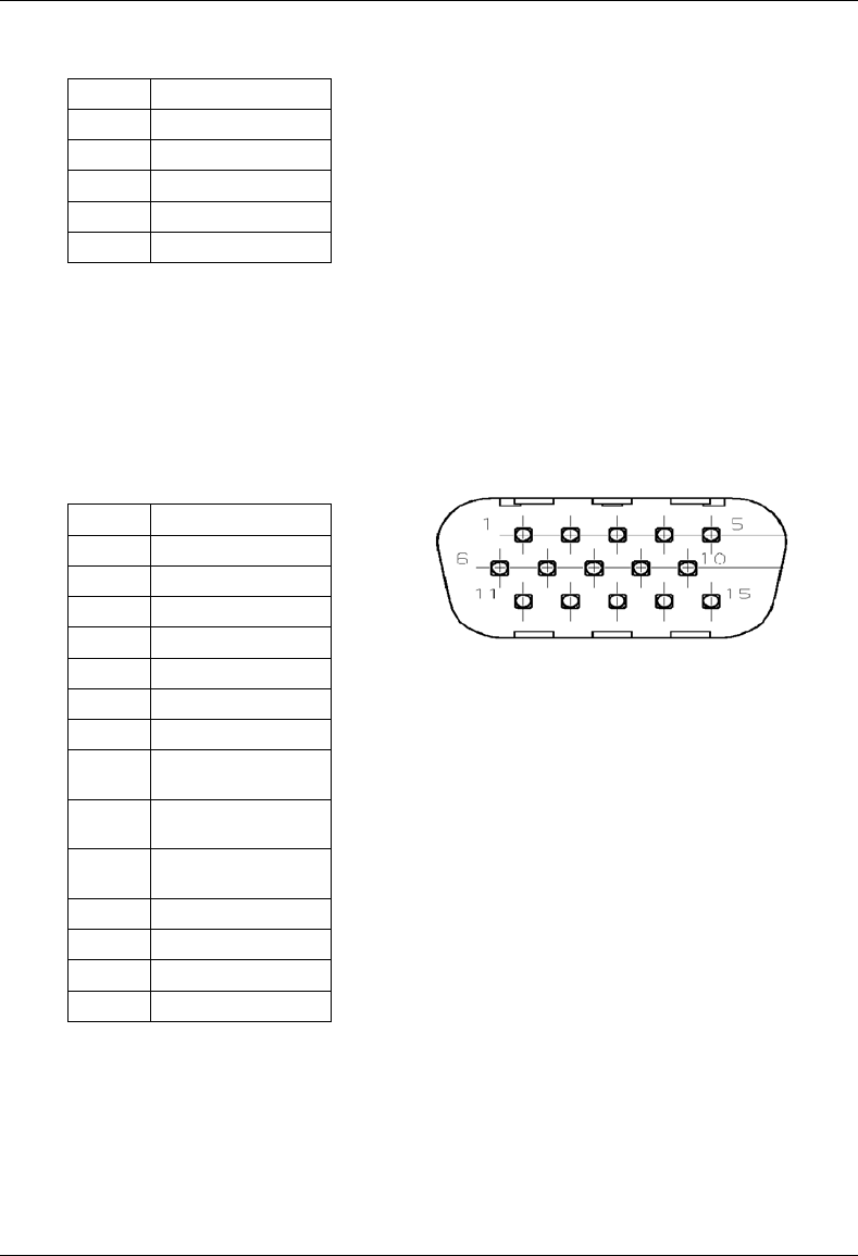
MC-Series System Installation & Testing
Scheduled and Unscheduled Maintenance
88 RadioFrame Networks, Inc.
10 15V Sec. Control
11 28V Prim. Control
12 28V Sec. Control
13 Fan1 Control
14 Fan2 Control
15 NC
7.5.2 RF Shelf Diagnostic Port
The pinout for the RF shelf diagnostic port connector is shown below. In the event of an alarm,
this connector provides access to more detailed information, since only major and minor alarm
states for an RF shelf are recognized by the system.
Table 5 RF Shelf Diagnostic Port Pinout
1 15V Prim Alarm
2 15V Sec Alarm
3 28V Prim Alarm
4 28V Sec Alarm
5 Fan1 Alarm
6 Fan2 Alarm
7 not currently used
8 GND
9 Test PA Rev RF
Power (Analog)
10 Test PA Fwd RF
Power (Analog )
11 Test PA Base
Temperature(Analog)
12 Test RF enable
13 LNA1 Alarm
14 LNA2 Alarm
15 PA VSWR Alarm
7.5.3 Alarm Descriptions
Within the RF shelf there are a number of failure mechanisms that will generate an alarm.
However, since only two alarm inputs are available in each RBS group, the alarms within the RF

MC-Series System Installation & Testing
Scheduled and Unscheduled Maintenance
RadioFrame Networks, Inc. 89
shelf must be AND'd together. The following table shows what constitutes a major alarm and
what constitutes a minor alarm.
Minor Alarm Major Alarm
SINGLE FAN FAILURE LNA (RECEIVE PATH) ALARM
LNA (DIVERSITY PATH) ALARM
PA ALARM
TWO FAN FAILURE
TWO LNA POWER SUPPLY FAILURE
TWO PA POWER SUPPLY FAILURE
ONE PA POWER SUPPLY FAILURE
ONE LNA POWER SUPPLY FAILURE
7.6 RadioBlade Alarm Handling
The iDEN RadioBlades track various faults and report those to the RadioBlade controller. These
faults are monitored and if the rate at which these faults occur surpasses a threshold, the blade is
locked. The RB will generate these faults as the result of normal actions such as re-syncing the
blade, locking and unlocking the RB and locking and unlocking the BR. For these reasons, only if
the blade continues to generate these faults under normal operating circumstances is an alarm
generated.
The RadioBlade tracks the following faults:
i. PLL1 Errors – The Phase Lock Loop #1 went out of lock.
ii. PLL2 Errors – The Phase Lock Loop #2 went out of lock.
iii. PLL3 Errors – The Phase Lock Loop #3 went out of lock.
iv. Tx Underrun – RB did not receive a packet in time to transmit.
v. Tx Overflow – RB received too many packets to transmit.
vi. Rx OverFlow – Sample buffer overflowed.
vii. Slot mismatch – Received packets were not consecutive.
viii. CRC errors – Received Ethernet packets had CRC errors.
If a RadioBlade generates enough errors such that it crosses the Bounce and Duration threshold
for that particular error, an alarm will be generated. This alarm will also cause the RadioBlade
Locking Policy to lock that RadioBlade. The following table lists the number of faults and the fault
period for an alarm to be generated.
Alarm Bounce Threshold (counts) Duration Threshold (minutes)
PLL 1 75 12
PLL 2 75 12

MC-Series System Installation & Testing
Scheduled and Unscheduled Maintenance
90 RadioFrame Networks, Inc.
Alarm Bounce Threshold (counts) Duration Threshold (minutes)
PLL 3 50 12
Tx Underrun 40 12
Tx Overflow 40 12
Rx Overflow 40 12
Slot Mismatch 40 12
CRC Errors 20 12
Packet Size Errors 20 12
Figure 28 RadioBlade fault Bounce and Duration for alarm generation.
In addition to the above-mentioned errors, if the system loses communication with a RadioBlade
or is unable to read the EEPROM from the blade, then that blade is put into an error state and if a
standby blade is available it will switch over automatically.
7.6.1 RadioBlade Policies
The RadioBlade locking policy is the action taken by the system whenever it has determined that
the RadioBlade should no longer be allowed to go active. This could be the result of an alarm,
insertion, removal, or the user specifically locking the RadioBlade.
In general, if a blade is taken out of service and a standby RB is available, then that RB will go
into service. If no standby RB is available then the BR will be locked.
7.6.1.1 Standby Blade
A Standby Blade is an extra RadioBlade that is installed in the system but does not have a
configured BR with which to register. To setup standby blades, make sure that there are more
RadioBlades for each RBS Group than Base Radios configured in the iDEN configuration page.
In all the conditions described below if RBs are present in a RBS that are in a hot standby state,
then locking the RB due to alarms, removal of a RB or administratively locking RBs, will result in
the hot Standby RB to be assigned to the BR that de-registered the locked RB.
7.6.1.2 Locking policy for RB with Errors
If the Radioblade generates enough faults such that it crosses the bounce and duration for that
particular error, an alarm will be generated. The RadioBlade controller then notifies the
associated BR, which then locks the RB.
If we determine there is a faulty RB in the system (i.e., RadioBlades that are generating errors),
we prevent them from coming up after a commanded reset/system reset, but the operator could
manually unlock the RB at which point the RB would be assigned to a BR (Note: this would not
prevent the system from locking it again if an excessive error condition occurs).
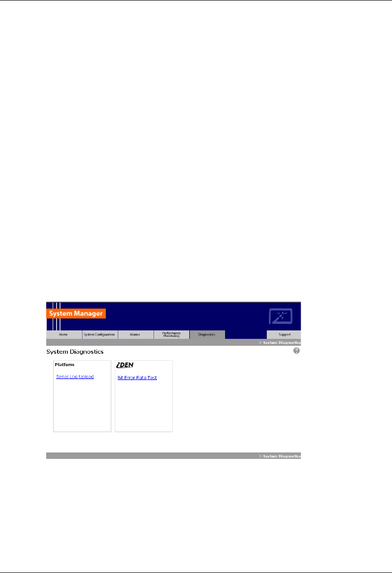
MC-Series System Installation & Testing
Scheduled and Unscheduled Maintenance
RadioFrame Networks, Inc. 91
7.6.1.3 Removal of RB:
When a RB is physically removed an event is generated in the System Manager Event Log
notifying the user about the RB removal. The RB controller will then de-register the RB from the
BR, which will result in locking the BR. A RB Insert event is generated when the RadioBlade is
inserted into the RBS.
7.6.1.4 Administratively locking a RB
Administratively locking a RadioBlade is when the RadioBlade lock icon on the RB Status page is
changed to lock. The following rules apply to this action.
1. If a locked RB is replaced, the new RB will be considered unlocked upon insertion. The
locking applies to a particular RB and not a particular Slot.
2. The locked RadioBlade will be preserved through a system reset.
3. RadioBlades in the disabled state will not be preserved through a system reset.
However, after a system reset, those blades that were originally in the disabled state due
to the effects of the locked RadioBlade and the particular policy will to go back into the
disabled state again.
7.7 Serial Log Upload Procedure
Complete this procedure before disconnecting and removing the BIC, AIC, RBS or an RF shelf
from the MC-Series System rack, or at the direction of RadioFrame Networks technical support.
1 Select the Diagnostics tab in System Manager, and then select the Serial Log Upload link.
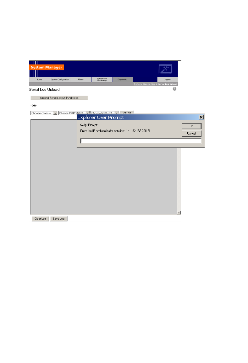
MC-Series System Installation & Testing
Scheduled and Unscheduled Maintenance
92 RadioFrame Networks, Inc.
2 Select the Upload Serial Log w/ IP Address button, and in the pop-up window, enter the IP
address of the component, and the select OK. Refer to Appendix B: Default IP Addresses.
Alternately, the component can be selected from the dropdown menus, though RadioFrame
Networks recommends using the IP address method.
3 Copy the contents of the serial log window into a text file, and save the text file.
4 Email the text file to the Technical Assistance Center at:
7.8 Power Down Procedure
When powering down the entire MC-Series System, follow these instructions.
1 Using the breakers on the PDU, power off equipment in the MC-Series System rack in the
following order:
• BIC
• AIC
• RBS 1 (RBS 2 and RBS 3 if present)
• RF Shelf 1, RF Shelf 2, and RF Shelf 3

MC-Series System Installation & Testing
Scheduled and Unscheduled Maintenance
RadioFrame Networks, Inc. 93
• CSU
• Secondary iSC-3; then ensure that the power switch on the front of the unit is in the OFF
position
• EAS; then ensure that the power switch on the front of the unit is in the OFF position
• Primary iSC-3; then ensure that the power switch on the front of the unit is in the OFF
position
7.9 Field Replaceable Unit (FRU) Procedures
The MC-Series System has been designed so that Field Repairable Units (FRUs) can be
replaced to restore normal system operation as quickly as possible. The following table lists
RadioFrame Networks FRUs. For equipment not supplied by RadioFrame Networks, follow
standard Nextel policies and procedures for FRU replacement. For more information, refer to
section 1.4.3 Field Replaceable Unit (FRU) Policy.
For support of RadioFrame Networks equipment, contact the RadioFrame Networks Technical
Assistance Center (TAC) at:
(US) 1-800-328-0847
Refer to section 1.4 Repair and Technical Support for more information.
Table 6 MC-Series System FRUs
P/N Description
176-0840-xx 800 MHz MC Series iDEN 2-Port RadioBlade (RB) Transceiver
176-0870-xx 800 MHz RF Shelf
176-0535-xx RadioBlade Transceiver Shelf (RBS)
176-0800-xx MC-15 Airlink Interface Chassis (AIC)
176-0900-xx MC-15 BTS Interface Chassis (BIC)
176-7570-xx Base Processing Card (BPC)
176-7550-xx Base Processing Card (BPC) with SPAM
176-7540-xx Common RadioFrame Interface Card (CRIC)
176-7562-xx Ethernet Rear Transition Module (ERTM)
176-7510-xx Signal Processing Array Module (SPAM)
176-0820-xx CRTC
176-7502-xx 4U Chassis
176-0600-xx PDU
176-1219-xx Fan Tray w/Fans for 4U Chassis
176-0011-xx Fan for RBS, RF Shelf, AIC & BIC
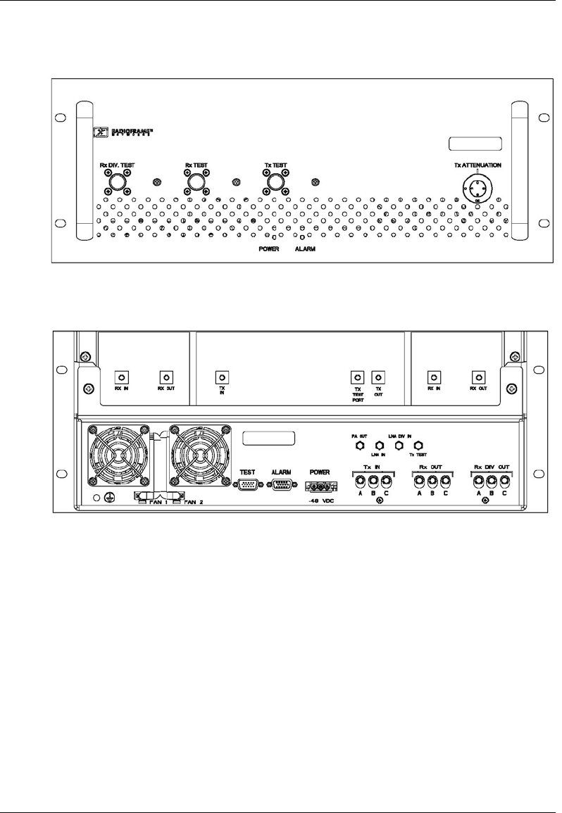
MC-Series System Installation & Testing
Scheduled and Unscheduled Maintenance
94 RadioFrame Networks, Inc.
7.9.1 RF Shelf
Figure 29 RF Shelf front view
Figure 30 RF Shelf rear view
7.9.1.1 RF Shelf Replacement Procedure
1 Power down RFN equipment in the following order using circuit breakers on the PDU:
• BIC
• AIC
• RBS 1 (power down RBS 2 and RBS 3 if they are present)
• RF shelf 1, 2, and 3
2 Disconnect cabling from the back of the chassis to be replaced.
DIVERSITY

MC-Series System Installation & Testing
Scheduled and Unscheduled Maintenance
RadioFrame Networks, Inc. 95
Refer to Appendix C Cabling Diagrams: 3-Sector Configuration and Appendix D Cabling
Diagrams: Omni Configuration.
For RF Shelf 1, disconnect the following cabling from the rear of RF Shelf 1:
Index Part Number Disconnect From To Type
P_1 820-0616-10 RF Shelf 1: power PDU: RF 1 power
G_3 820-0609-00 RF Shelf 1: ground GND BAR ground
RF_1 820-0611-20 RF Shelf 1: Tx IN A RBS 1: Tx A RF cable
RF_4 820-0611-20 RF Shelf 1: Rx OUT A RBS 1: Rx A RF cable
RF_9 820-0610-30 RF Shelf 1: TX OUT TOR: Tx 1 RF cable
RF_10 820-0610-30 RF Shelf 1: RX IN TOR: Rx 1 RF cable
AL_1 820-0607-00 RF Shelf 1: ALARM RBS: ALARM INPUT A serial
For RF Shelf 2, disconnect the following cabling from the rear of RF Shelf 2:
Index Part Number Disconnect From To Type
P_2 820-0616-10 RF Shelf 2: power PDU: RF 2 power
G_4 820-0609-00 RF Shelf 2: ground GND BAR ground
RF_2 820-0611-20 RF Shelf 2: Tx IN B RBS 1: Tx B RF cable
RF_5 820-0611-20 RF Shelf 2: Rx OUT B RBS 1: Rx B RF cable
RF_15 820-0610-30 RF Shelf 2: TX OUT TOR: Tx 2 RF cable
RF_16 820-0610-30 RF Shelf 2: RX IN TOR: Rx 2 RF cable
AL_2 820-0607-00 RF Shelf 2: ALARM RBS: ALARM INPUT B serial
For RF Shelf 3, disconnect the following cabling from the rear of RF Shelf 3:
Index Part Number Disconnect From To Type
P_3 820-0616-10 RF Shelf 3: power PDU: RF 3 power
G_5 820-0609-00 RF Shelf 3: ground GND BAR ground
RF_1 820-0611-20 RF Shelf 3: Tx IN C RBS 1: Tx C RF cable
RF_4 820-0611-20 RF Shelf 3: Rx OUT C RBS 1: Rx C RF cable
RF_9 820-0610-30 RF Shelf 3: TX OUT TOR: Tx 3 RF cable
RF_10 820-0610-30 RF Shelf 3: RX IN TOR: Rx 3 RF cable
AL_1 820-0607-00 RF Shelf 3: ALARM RBS: ALARM INPUT C serial
3 Remove the 4 front mounting screws and remove the RF shelf from the rack, and then
package it for shipment.
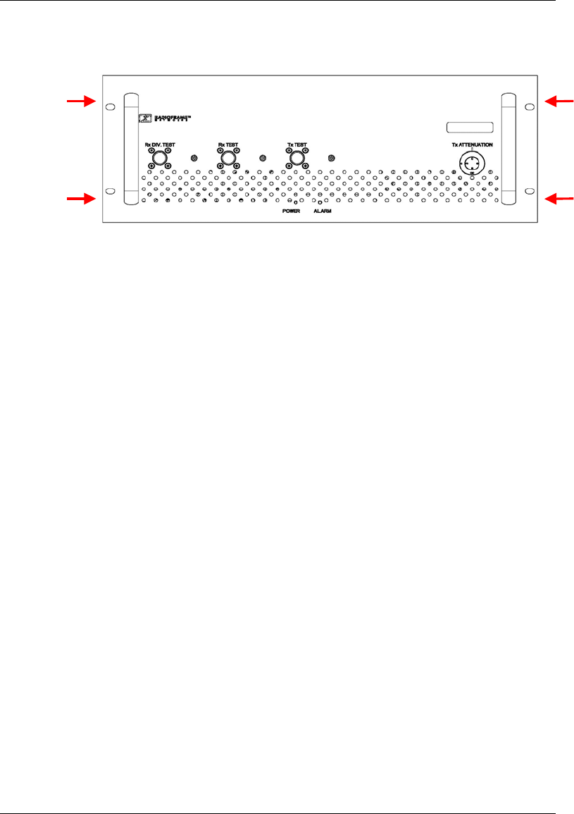
MC-Series System Installation & Testing
Scheduled and Unscheduled Maintenance
96 RadioFrame Networks, Inc.
4 Mount the replacement RF shelf.
While supporting the RF shelf, slide it into the cabinet mounting position. Secure the RF shelf
to the cabinet mounting rails using the four mounting screws provided with the unit. Tighten
the screws to 4.5 Nm (40 in-lb).
5 Reconnect the cabling to the replacement chassis as defined in Step 2.
Use the SMA torque wrench for all SMA connectors.
6 Using the breakers on the PDU, turn up the BIC, AIC, and RBS 1 (and RBS 2 and RBS 3 if
present), and then verify that the components are operational before proceeding.
7 Wait approximately 3 minutes for the following indicators:
• RBS: The STATUS LED for each group will light green in this order: A, B, and then C.
• RBS: The RADIOBLADE STATUS LEDs will light red and then green for each present
RadioBlade. If no RB is present, the LED will not light. To verify the contents of the RBS,
pull out the shelf (powering off is not required) and inspect the RadioBlades and their
respective status LEDs. Reinsert the RBS. To do this, press up on one side rail locking
arm and press down on the other side rail locking arm, and then push the unit into the
rack (see the following illustration).
• BIC CRIC and AIC CRIC: The POWER and STATUS LEDs will light red and then green.
All other BIC and AIC card LEDs will light green.
8 Using the breaker on the PDU, turn up RF Shelf 1, RF Shelf 2, and RF Shelf 3 and verify
that each RF shelf is operational before proceeding. The POWER and ALARM LEDs on the
front of the RF Shelf will light green.
9 Refer to sections 5.4, 5.5 and 5.6 for configuration and verification.
7.9.1.2 Replacing a Fan in the RBS or an RF Shelf
1 Verify which fan has failed (look at each fan and determine which fan(s) are not turning).
2 Disconnect power from the fan.
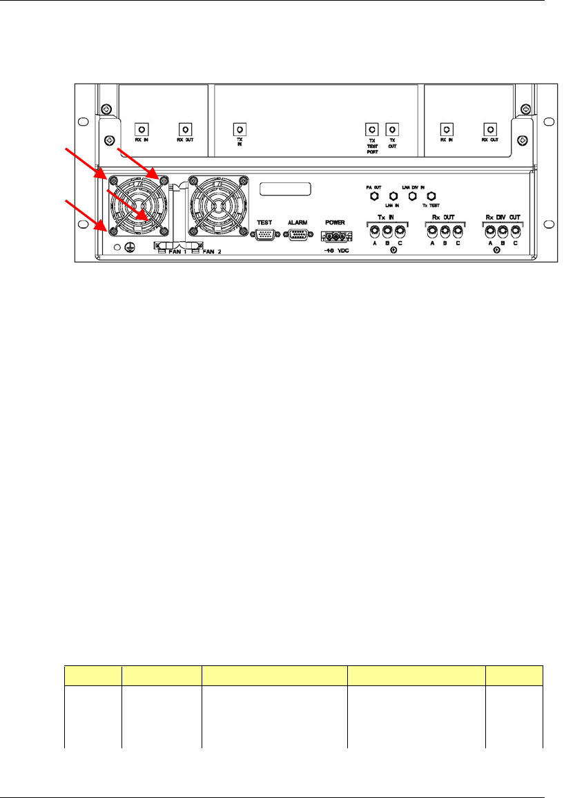
MC-Series System Installation & Testing
Scheduled and Unscheduled Maintenance
RadioFrame Networks, Inc. 97
3 Remove the four fan mounting screws.
4 Replace the fan.
5 Install the four fan mounting screws.
NOTE: Install the finger guard so that the space is aligned vertically.
6 Connect the fan power cable.
7 Verify that the fan is working.
7.9.2 Replacing a Chassis: BIC, AIC, or RBS
7.9.2.1 BIC
1 Power down RFN equipment in the following order using circuit breakers on the PDU:
• BIC
• AIC
• RBS 1 (power down RBS 2 and RBS 3 if they are present)
• RF Shelves 1,2 and 3
2 Disconnect cabling from the back of the chassis to be replaced.
Refer to Appendix C Cabling Diagrams: 3-Sector Configuration and Appendix D Cabling
Diagrams: Omni Configuration.
For the BIC, disconnect the following cabling from the rear of the BIC only:
Index Part Number Disconnect From To Type
P_11 820-0614-00 BIC: power PDU: BIC power
G_13 820-0609-00 BIC: ground GND BAR ground
DAT_4* 111-0565-00 BIC: ERTM PORT 1 BIC: CRTC 10baseT - ISC UTP
DAT_5 111-0565-00 BIC: ERTM PORT 2 AIC: ERTM PORT 4 UTP
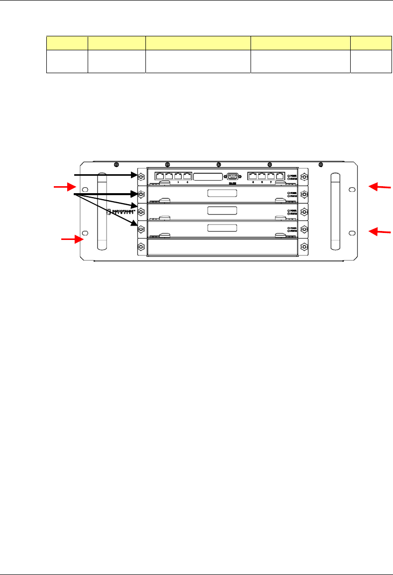
MC-Series System Installation & Testing
Scheduled and Unscheduled Maintenance
98 RadioFrame Networks, Inc.
Index Part Number Disconnect From To Type
DAT_6 111-0001-02 BIC: CRTC 10base2 - ISC ISC 1: 10B2-1 COAX
CLK_1 111-0001-02 BIC: ERTM 5MHz/1PPS IN ISC 1: SITE REF OUT 1 COAX
* Remove both ends of this cable and keep it for the replacement BIC.
3 Remove the chassis from the rack, and package it for shipment.
4 Remove the 4 front mounting screws from the front of the unit (shown with arrows).
Figure 31 Front view of BIC
5 Mount the replacement chassis.
While supporting the chassis, slide the chassis into the cabinet mounting position. Secure the
chassis to the cabinet mounting rails using the four mounting screws provided with the unit.
Tighten the screws to 4.5 Nm (40 in-lb).
6 Reconnect the cabling to the replacement chassis as defined in Step 2.
Use the SMA torque wrench for all SMA connectors.
7 Using the breakers on the PDU, turn up the BIC, AIC, and RBS 1 (and RBS 2 and RBS 3 if
present), and then verify that the components are operational before proceeding.
Wait approximately 3 minutes for the following indicators:
• RBS: The STATUS LED for each group will light green in this order: A, B, and then C.
• RBS: The RADIOBLADE STATUS LEDs will light red and then green for each present
RadioBlade. If no RB is present, the LED will not light. To verify the contents of the RBS,
pull out the shelf (powering off is not required) and inspect the RadioBlades and their
respective status LEDs. Reinsert the RBS. To do this, press up on one side rail locking
arm and press down on the other side rail locking arm, and then push the unit into the
rack (see the following illustration).
• BIC CRIC and AIC CRIC: The POWER and STATUS LEDs will light red and then green.
All other BIC and AIC card LEDs will light green.
BPC
BIC CRIC
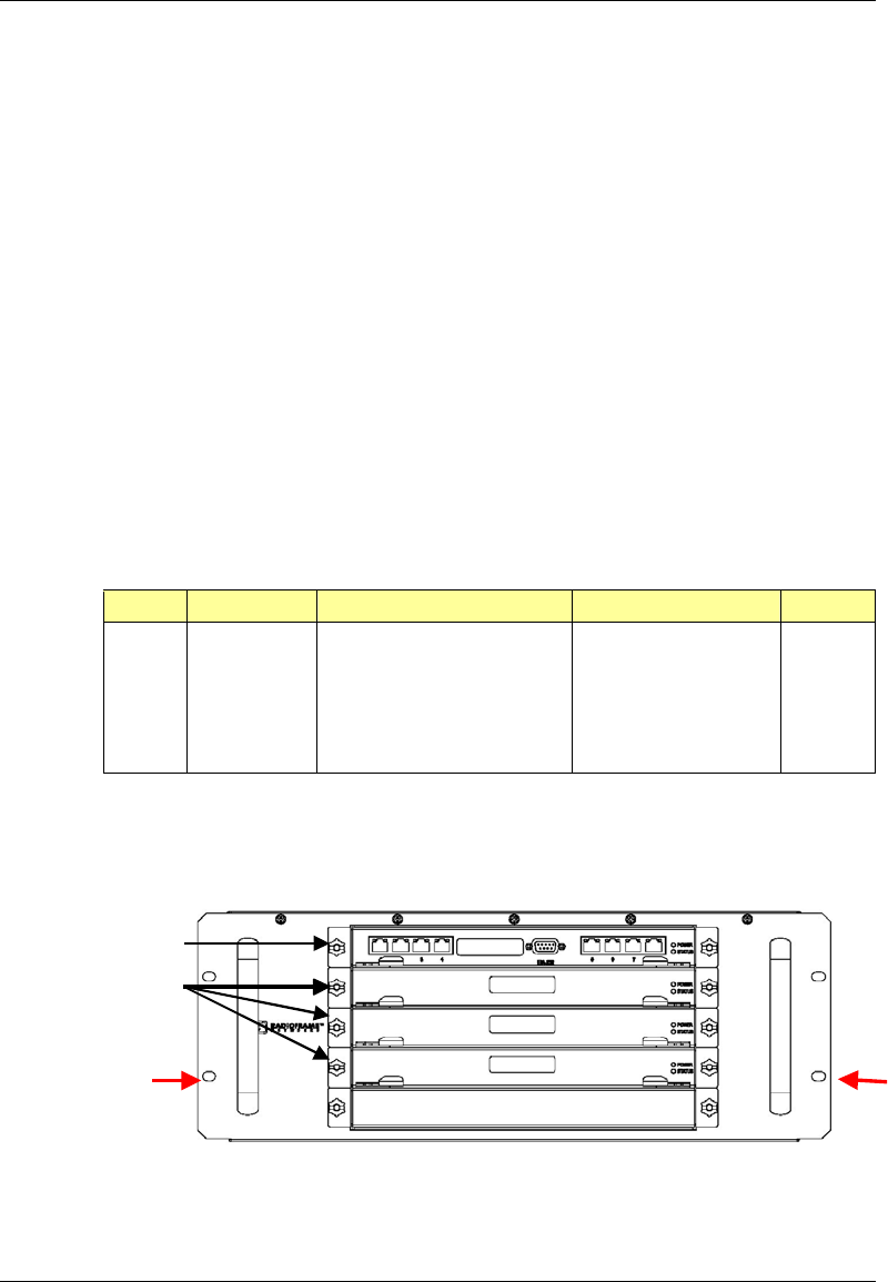
MC-Series System Installation & Testing
Scheduled and Unscheduled Maintenance
RadioFrame Networks, Inc. 99
8 Using the breaker on the PDU, turn up each RF Shelf and then verify that each RF Shelf is
operational before proceeding. The POWER and ALARM LEDs on the front of the RF Shelf
will light green.
9 Complete the procedures in sections 5.4, 5.5 and 5.6.
7.9.2.2 AIC
1 Power down RFN equipment in the following order using circuit breakers on the PDU:
• BIC
• AIC
• RBS 1 (power down RBS 2 and RBS 3 if they are present)
• RF Shelves 1,2 and 3
2 Disconnect cabling from the back of the chassis to be replaced.
Refer to Appendix C Cabling Diagrams: 3-Sector Configuration and Appendix D Cabling
Diagrams: Omni Configuration.
For the AIC, disconnect the following cabling from the rear of the AIC only:
Index Part Number Disconnect From To Type
P_12 820-0614-10 AIC: power PDU: AIC power
G_13 820-0609-00 AIC: ground GND BAR ground
DAT_1 111-0566-00 AIC: ERTM PORT 1 RBS 1: 10/100 RFN A UTP
DAT_2 111-0566-00 AIC: ERTM PORT 2 RBS 1: 10/100 RFN B UTP
DAT_3 111-0566-00 AIC: ERTM PORT 3 RBS 1: 10/100 RFN C UTP
DAT_5 111-0565-00 AIC: ERTM PORT 4 BIC: ERTM PORT 2 UTP
3 Remove the chassis from the rack, and package it for shipment.
4 Remove the 4 front mounting screws (shown with arrows).
Figure 32 Front view of AIC
aBPC
PC
AIC CRIC

MC-Series System Installation & Testing
Scheduled and Unscheduled Maintenance
100 RadioFrame Networks, Inc.
5 Mount the replacement chassis.
While supporting the chassis, slide the chassis into the cabinet mounting position. Secure the
chassis to the cabinet mounting rails using the four mounting screws provided with the unit.
Tighten the screws to 4.5 Nm (40 in-lb).
6 Reconnect the cabling to the replacement chassis as defined in Step 2.
Use the SMA torque wrench for all SMA connectors.
7 Using the breakers on the PDU, turn up the BIC, AIC, and RBS 1 (and RBS 2 and RBS 3 if
present), and then verify that the components are operational before proceeding.
Wait approximately 3 minutes for the following indicators:
• RBS: The STATUS LED for each group will light green in this order: A, B, and then C.
• RBS: The RADIOBLADE STATUS LEDs will light red and then green for each present
RadioBlade. If no RB is present, the LED will not light. To verify the contents of the RBS,
pull out the shelf (powering off is not required) and inspect the RadioBlades and their
respective status LEDs. Reinsert the RBS. To do this, press up on one side rail locking
arm and press down on the other side rail locking arm, and then push the unit into the
rack (see the following illustration).
• BIC CRIC and AIC CRIC: The POWER and STATUS LEDs will light red and then green.
All other BIC and AIC card LEDs will light green.
8 Using the breaker on the PDU, turn up each RF Shelf and then verify that each RF Shelf is
operational before proceeding. The POWER and ALARM LEDs on the front of the RF Shelf
will light green.
9 Complete the procedures in sections 5.4, 5.5 and 5.6.
7.9.2.3 RBS 1 (power down RBS 2 and RBS 3 if they are present)
1 Power down RFN equipment in the following order using circuit breakers on the PDU:
• BIC
• AIC
• RBS 1 (power down RBS 2 and RBS 3 if they are present)
• RF Shelves 1,2 and 3
2 Disconnect cabling from the back of the RBS to be replaced.
For RBS 1, disconnect the following cabling from the rear of the RBS 1 only:
NOTE: If RBS 2 and RBS 3 are present, refer to Appendix C Cabling Diagrams: 3-Sector
Configuration and Appendix D Cabling Diagrams: Omni Configuration.
Index Part Number Disconnect From To Type
P_6 820-0616-50 RBS 1: power PDU: RBS 1 power
G_8 820-0609-00 RBS 1: ground GND BAR ground
RF_1 820-0611-20 RBS 1: Tx A RF Shelf 1: Tx IN A RF cable
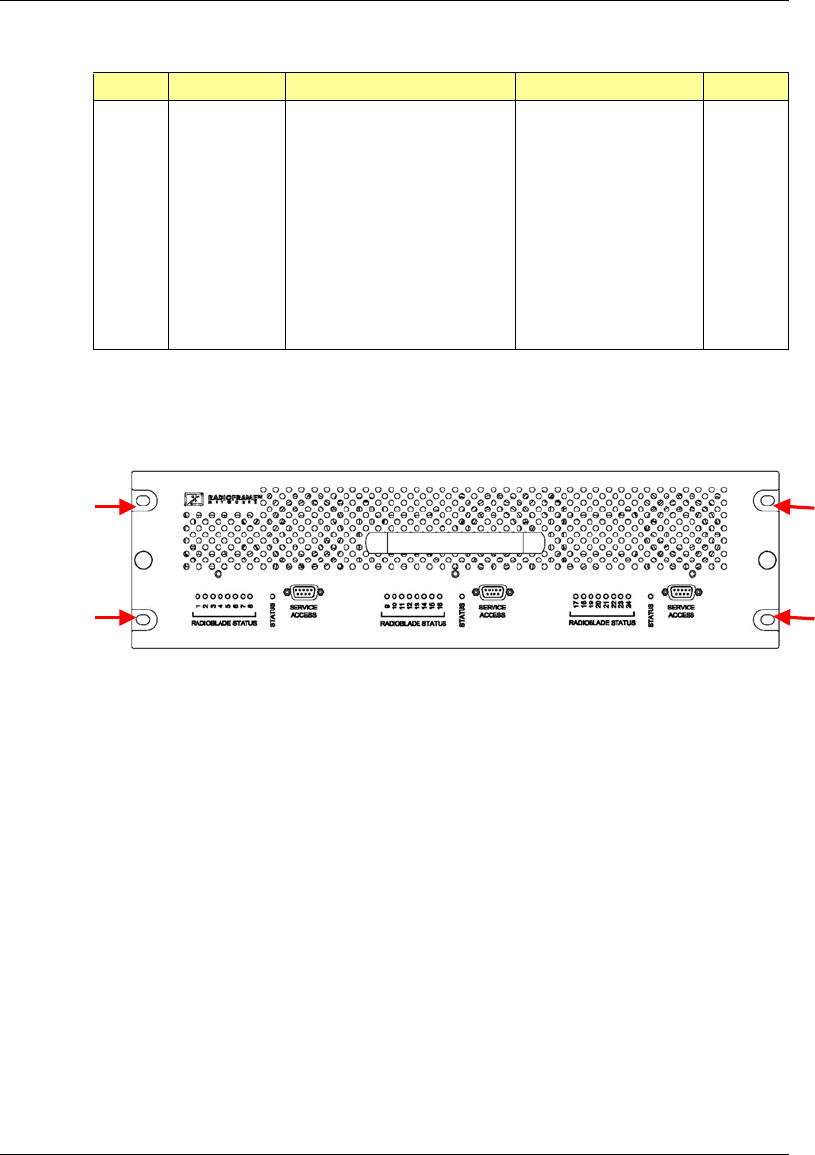
MC-Series System Installation & Testing
Scheduled and Unscheduled Maintenance
RadioFrame Networks, Inc. 101
Index Part Number Disconnect From To Type
RF_4 820-0611-20 RBS 1: Rx A RF Shelf 1: Rx OUT A RF cable
AL_1 820-0607-00 RBS: ALARM INPUT A RF Shelf 1: ALARM serial
DAT_1 111-0566-00 RBS 1: 10/100 RFN A AIC: ERTM PORT 1 UTP
RF_2 820-0611-20 RBS 1: Tx B RF Shelf 2: Tx IN B RF cable
RF_5 820-0611-20 RBS 1: Rx B RF Shelf 2: Rx OUT B RF cable
AL_2 820-0607-00 RBS: ALARM INPUT B RF Shelf 2: ALARM serial
DAT_2 111-0566-00 RBS 1: 10/100 RFN B AIC: ERTM PORT 2 UTP
RF_3 820-0611-20 RBS 1: Tx C RF Shelf 3: Tx IN C RF cable
RF_6 820-0611-20 RBS 1: Rx C RF Shelf 3: Rx OUT C RF cable
AL_3 820-0607-00 RBS: ALARM INPUT C RF Shelf 3: ALARM serial
DAT_3 111-0566-00 RBS 1: 10/100 RFN C AIC: ERTM PORT 3 UTP
3 Remove the 4 front mounting screws, remove the chassis from the rack, and then package it
for shipment.
Figure 33 Front view of RBS
4 Mount the replacement chassis.
While supporting the chassis, slide the chassis into the cabinet mounting position. Secure the
chassis to the cabinet mounting rails using the four mounting screws provided with the unit.
Tighten the screws to 4.5 Nm (40 in-lb).
5 Reconnect the cabling to the replacement chassis as defined in Step 2.
Use the SMA torque wrench for all SMA connectors.
6 Using the breakers on the PDU, turn up the BIC, AIC, and RBS 1 (and RBS 2 and RBS 3 if
present), and then verify that the components are operational before proceeding.
Wait approximately 3 minutes for the following indicators:
• RBS: The STATUS LED for each group will light green in this order: A, B, and then C.
• RBS: The RADIOBLADE STATUS LEDs will light red and then green for each present
RadioBlade. If no RB is present, the LED will not light. To verify the contents of the RBS,
pull out the shelf (powering off is not required) and inspect the RadioBlades and their

MC-Series System Installation & Testing
Scheduled and Unscheduled Maintenance
102 RadioFrame Networks, Inc.
respective status LEDs. Reinsert the RBS. To do this, press up on one side rail locking
arm and press down on the other side rail locking arm, and then push the unit into the
rack (see the following illustration).
• BIC CRIC and AIC CRIC: The POWER and STATUS LEDs will light red and then green.
All other BIC and AIC card LEDs will light green.
7 Using the breaker on the PDU, turn up each RF Shelf and then verify that each RF Shelf is
operational before proceeding.
The POWER and ALARM LEDs on the front of the RF Shelf will light green.
8 Complete the procedures in sections 5.4, 5.5 and 5.6.
7.9.3 BIC/AIC– FRU Replacement Procedure
BEFORE REPLACING ANY CARD (board) in the BIC or AIC, power down RFN equipment in the
following order using circuit breakers on the PDU:
• BIC
• AIC
• RBS 1 (power down RBS 2 and RBS 3 if they are present)
• RF Shelves 1, 2 and 3
7.9.3.1 Replacing the CRIC (BIC or AIC)
1 Before replacing any card (board) in the BIC or AIC, power down RFN equipment in the
following order using circuit breakers on the PDU:
• BIC
• AIC
• RBS 1 (power down RBS 2 and RBS 3 if they are present)
• RF Shelves 1, 2 and 3
2 Always use a static grounding wrist strap before handling any board—do not attach the wrist
strap to any painted surface on the chassis unit.
3 Facing the BIC or AIC, remove the CRIC that is to be replaced, following these guidelines:
• Loosen the blue knurled knobs on both sides of the board.
• Pull firmly on the tabs located on the bottom of the CRIC.
• Gently slide the CRIC straight out and away from the chassis unit so as not to damage
any components contained on the board.
4 Remove the replacement CRIC from its antistatic packaging and insert it into the chassis unit
as shown in the following illustration, and follow these guidelines:
• Do not jam the board in any way while inserting it.
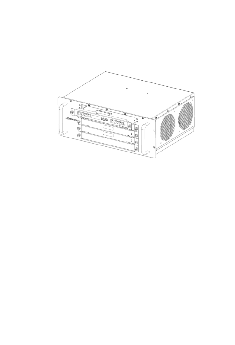
MC-Series System Installation & Testing
Scheduled and Unscheduled Maintenance
RadioFrame Networks, Inc. 103
• Do not mount the board in any orientation other than that specified in the diagram.
• Insert the board straight into the chassis unit so as not to damage any components
contained on the board.
• Press firmly to seat the board into the connectors within the chassis unit.
• Tighten the blue knurled knobs on each end of the board finger tight only—do not use a
screwdriver to tighten the screws and do not over tighten.
Figure 34 Replacing the CRIC in the BIC or AIC.
5 Place the old board in the antistatic packaging for shipment.
6 Using the breakers on the PDU, turn up the BIC, AIC, and RBS 1 (and RBS 2 and RBS 3 if
present), and then verify that the components are operational before proceeding.
Wait approximately 3 minutes for the following indicators:
• RBS: The STATUS LED for each group will light green in this order: A, B, and then C.
• RBS: The RADIOBLADE STATUS LEDs will light red and then green for each present
RadioBlade. If no RB is present, the LED will not light. To verify the contents of the RBS,
pull out the shelf (powering off is not required) and inspect the RadioBlades and their
respective status LEDs. Reinsert the RBS. To do this, press up on one side rail locking
arm and press down on the other side rail locking arm, and then push the unit into the
rack (see the following illustration).
• BIC CRIC and AIC CRIC: The POWER and STATUS LEDs will light red and then green.
All other BIC and AIC card LEDs will light green.
7 Using the breaker on the PDU, turn up each RF Shelf and then verify that each RF Shelf is
operational before proceeding.
The POWER and ALARM LEDs on the front of the RF Shelf will light green.
8 FOR THE BIC CRIC ONLY: complete the procedures in sections 5.4, 5.5 and 5.6.
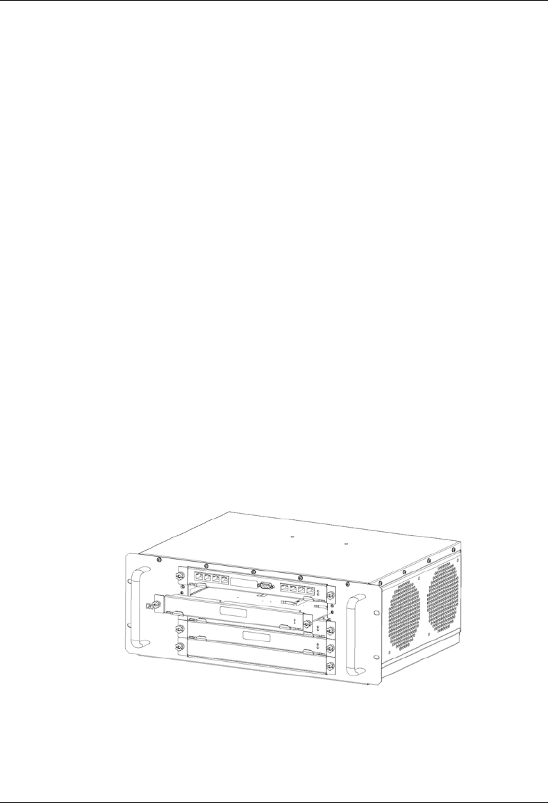
MC-Series System Installation & Testing
Scheduled and Unscheduled Maintenance
104 RadioFrame Networks, Inc.
7.9.3.2 BPC (BIC) or BPC+SPAM (AIC)
1 Before replacing any card (board) in the BIC or AIC, power down RFN equipment in the
following order using circuit breakers on the PDU:
• BIC
• AIC
• RBS 1 (power down RBS 2 and RBS 3 if they are present)
• RF Shelves 1, 2 and 3
2 Always use a static grounding wrist strap before handling any board—do not attach the wrist
strap to any painted surface on the chassis unit.
3 Facing the chassis unit, remove the BPC that is to be replaced, or the blank faceplate,
following these guidelines:
• Loosen the blue knurled knobs on both sides of the board.
• Pull firmly on the tabs located on the bottom of the BPC you are replacing.
• Gently slide the BPC straight out and away from the chassis unit so as not to damage
any components contained on the board.
4 Remove the BPC from its antistatic packaging and insert it into the chassis unit as shown in
the following illustration, and follow these guidelines:
• Do not jam the board in any way while inserting it.
• Do not mount the board in any orientation other than that specified in the diagram.
• Insert the board straight into the chassis unit so as not to damage any components
contained on the board.
• Press firmly to seat the board into the connectors within the chassis unit.
• Tighten the blue knurled knobs on each end of the board finger tight only—do not use a
screwdriver to tighten the screws and do not over tighten.
Figure 35 Replacing the BPC in the BIC or the BPC+SPAM in the AIC.

MC-Series System Installation & Testing
Scheduled and Unscheduled Maintenance
RadioFrame Networks, Inc. 105
5 Place the old board in the antistatic packaging for shipment.
6 Using the breakers on the PDU, turn up the BIC, AIC, and RBS 1 (and RBS 2 and RBS 3 if
present), and then verify that the components are operational before proceeding.
Wait approximately 3 minutes for the following indicators:
• RBS: The STATUS LED for each group will light green in this order: A, B, and then C.
• RBS: The RADIOBLADE STATUS LEDs will light red and then green for each present
RadioBlade. If no RB is present, the LED will not light. To verify the contents of the RBS,
pull out the shelf (powering off is not required) and inspect the RadioBlades and their
respective status LEDs. Reinsert the RBS. To do this, press up on one side rail locking
arm and press down on the other side rail locking arm, and then push the unit into the
rack (see the following illustration).
• BIC CRIC and AIC CRIC: The POWER and STATUS LEDs will light red and then green.
All other BIC and AIC card LEDs will light green.
7 Using the breaker on the PDU, turn up each RF Shelf and then verify that each RF Shelf is
operational before proceeding.
The POWER and ALARM LEDs on the front of the RF Shelf will light green.
7.9.3.3 ERTM
1 Before replacing any card (board) in the BIC or AIC, power down RFN equipment in the
following order using circuit breakers on the PDU:
• BIC
• AIC
• RBS 1 (power down RBS 2 and RBS 3 if they are present)
• RF Shelves 1, 2 and 3
2 Always use a static grounding wrist strap before handling any board—do not attach the wrist
strap to any painted surface on the chassis unit.
3 Facing the rear of the BIC or AIC, remove the ERTM that is to be replaced following these
guidelines:
• Loosen the blue knurled knobs on both sides of the board.
• Pull firmly on the tabs located on the bottom of the ERTM you are replacing.
• Gently slide the ERTM straight out and away from the chassis unit so as not to damage
any components contained on the board.
4 Remove the ERTM from its antistatic packaging and insert it into the chassis unit as shown in
the following illustration, and follow these guidelines:
• Do not jam the board in any way while inserting it.
• Do not mount the board in any orientation other than that specified in the diagram.
• Insert the board straight into the chassis unit so as not to damage any components
contained on the board.
• Press firmly to seat the board into the connectors within the chassis unit.

MC-Series System Installation & Testing
Scheduled and Unscheduled Maintenance
106 RadioFrame Networks, Inc.
• Tighten the blue knurled knobs on each end of the board finger tight only—do not use a
screwdriver to tighten the screws and do not over tighten.
Figure 36 Rear of BIC (ERTM and CRTC) and AIC (ERTM only).
5 Place the old board in the antistatic packaging for shipment.
6 Using the breakers on the PDU, turn up the BIC, AIC, and RBS 1 (and RBS 2 and RBS 3 if
present), and then verify that the components are operational before proceeding.
Wait approximately 3 minutes for the following indicators:
• RBS: The STATUS LED for each group will light green in this order: A, B, and then C.
• RBS: The RADIOBLADE STATUS LEDs will light red and then green for each present
RadioBlade. If no RB is present, the LED will not light. To verify the contents of the RBS,
pull out the shelf (powering off is not required) and inspect the RadioBlades and their
respective status LEDs. Reinsert the RBS. To do this, press up on one side rail locking
arm and press down on the other side rail locking arm, and then push the unit into the
rack (see the following illustration).
• BIC CRIC and AIC CRIC: The POWER and STATUS LEDs will light red and then green.
All other BIC and AIC card LEDs will light green.
7 Using the breaker on the PDU, turn up each RF Shelf and then verify that each RF Shelf is
operational before proceeding.
The POWER and ALARM LEDs on the front of the RF Shelf will light green.
7.9.3.4 CRTC
1 Before replacing any card (board) in the BIC, power down RFN equipment in the following
order using circuit breakers on the PDU:
• BIC
• AIC
ERTM
CRTC
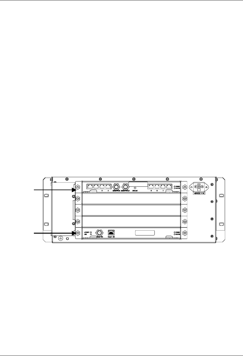
MC-Series System Installation & Testing
Scheduled and Unscheduled Maintenance
RadioFrame Networks, Inc. 107
• RBS 1 (power down RBS 2 and RBS 3 if they are present)
• RF Shelves 1, 2 and 3
2 Always use a static grounding wrist strap before handling any board—do not attach the wrist
strap to any painted surface on the chassis unit.
3 Facing the rear of the BIC, remove the CRTC following these guidelines:
• Loosen the blue knurled knobs on both sides of the board.
• Pull firmly on the tabs located on the bottom of the CRTC.
• Gently slide the CRTC straight out and away from the chassis unit so as not to damage
any components contained on the board.
4 Remove the CRTC from its antistatic packaging and insert it into the chassis unit as shown in
the following illustration, and follow these guidelines:
• Do not jam the board in any way while inserting it.
• Do not mount the board in any orientation other than that specified in the diagram.
• Insert the board straight into the chassis unit so as not to damage any components
contained on the board.
• Press firmly to seat the board into the connectors within the chassis unit.
• Tighten the blue knurled knobs on each end of the board finger tight only—do not use a
screwdriver to tighten the screws and do not over tighten.
5 Place the old board in the antistatic packaging for shipment.
6 Using the breakers on the PDU, turn up the BIC, AIC, and RBS 1 (and RBS 2 and RBS 3 if
present), and then verify that the components are operational before proceeding.
Wait approximately 3 minutes for the following indicators:
• RBS: The STATUS LED for each group will light green in this order: A, B, and then C.
• RBS: The RADIOBLADE STATUS LEDs will light red and then green for each present
RadioBlade. If no RB is present, the LED will not light. To verify the contents of the RBS,
pull out the shelf (powering off is not required) and inspect the RadioBlades and their
respective status LEDs. Reinsert the RBS. To do this, press up on one side rail locking
arm and press down on the other side rail locking arm, and then push the unit into the
rack (see the following illustration).
ERTM
CRTC
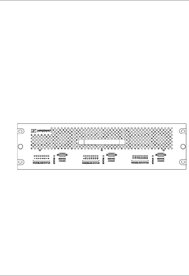
MC-Series System Installation & Testing
Scheduled and Unscheduled Maintenance
108 RadioFrame Networks, Inc.
• BIC CRIC and AIC CRIC: The POWER and STATUS LEDs will light red and then green.
All other BIC and AIC card LEDs will light green.
7 Using the breaker on the PDU, turn up each RF Shelf and then verify that each RF Shelf is
operational before proceeding.
The POWER and ALARM LEDs on the front of the RF Shelf will light green.
7.9.4 RadioBlade Replacement
The MC-Series System supports hot swapping of RadioBlades. This means that replacement of a
RadioBlade can be done while the system is live and does not require a system reset. When
RadioBlades are hot swapped no alarm is generated. Rather, an RB lock and unlock event is
placed in the System Manager Event Log.
Each RadioBlade is shipped wrapped in antistatic packaging, along with a lockdown strap and
screw for securing the RB in the RadioBlade Shelf (RBS).
NOTE: Use an SMA torque wrench (such as the Huber & Suhner 742-0-0-21 SMA torque
wrench) for removing and installing RBs.
Figure 37 Front view of the RadioBlade Shelf (RBS)
7.9.4.1 2-port Single Ch 800 RB
1 Take the RadioBlade out of service by locking it (refer to the procedure in Appendix G,
section G.4 Locking and Unlocking a RadioBlade).
The RBS is divided into three groups (A, B, and C) from left to right. Slots in each group are
numbered as follows, from front to back:
• Group A: slots 1 through 8
• Group B: slots 9 through 16
• Group C: slots 17 through 24
2 Pull out the RBS using the handle on the front of the unit.
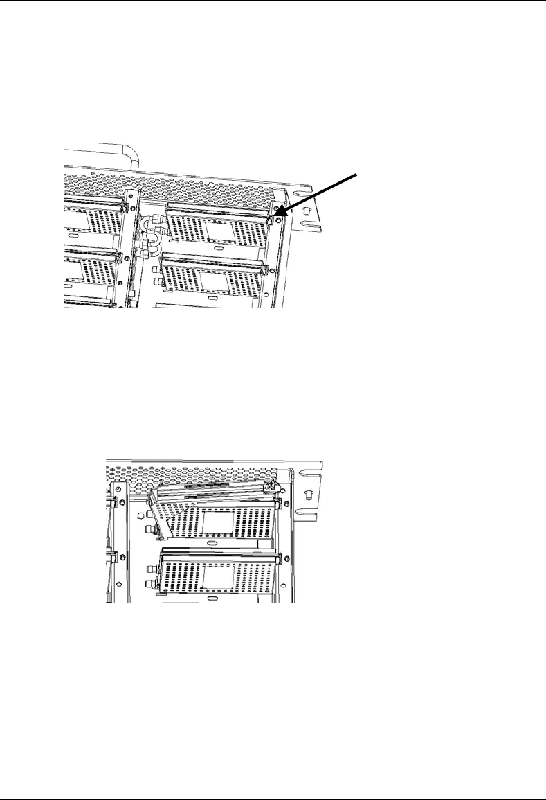
MC-Series System Installation & Testing
Scheduled and Unscheduled Maintenance
RadioFrame Networks, Inc. 109
3 Remove the RadioBlade that is to be replaced (see the following illustration).
Using the SMA torque wrench, disconnect the Rx and Tx cables from the RadioBlade. Then,
loosen the screw of the lockdown strap covering the RadioBlade, and remove the strap and
screw and place them aside. Then gently lift and remove the RB from the slot in the RBS
backplane. Place the RB in anti-static packaging for shipment.
4 Un-package the replacement RadioBlade to be inserted into the RBS.
5 Insert the RadioBlade into the specified slot in the RBS until the connector seats firmly into
the backplane of the RBS.
6 Place the lockdown strap over the RadioBlade by inserting the two feet on the strap into the
slots on the RBS backplane, and then hand tighten the screw into place.
7 Connect the Rx and Tx cables to the correct ports on the RadioBlade, and use the SMA
torque wrench to tighten.
8 Re-insert the RBS into its chassis. To do this, press up on one side rail locking arm and press
down on the other side rail locking arm, and then push the unit into the rack (see the following
illustration).
lockdown strap
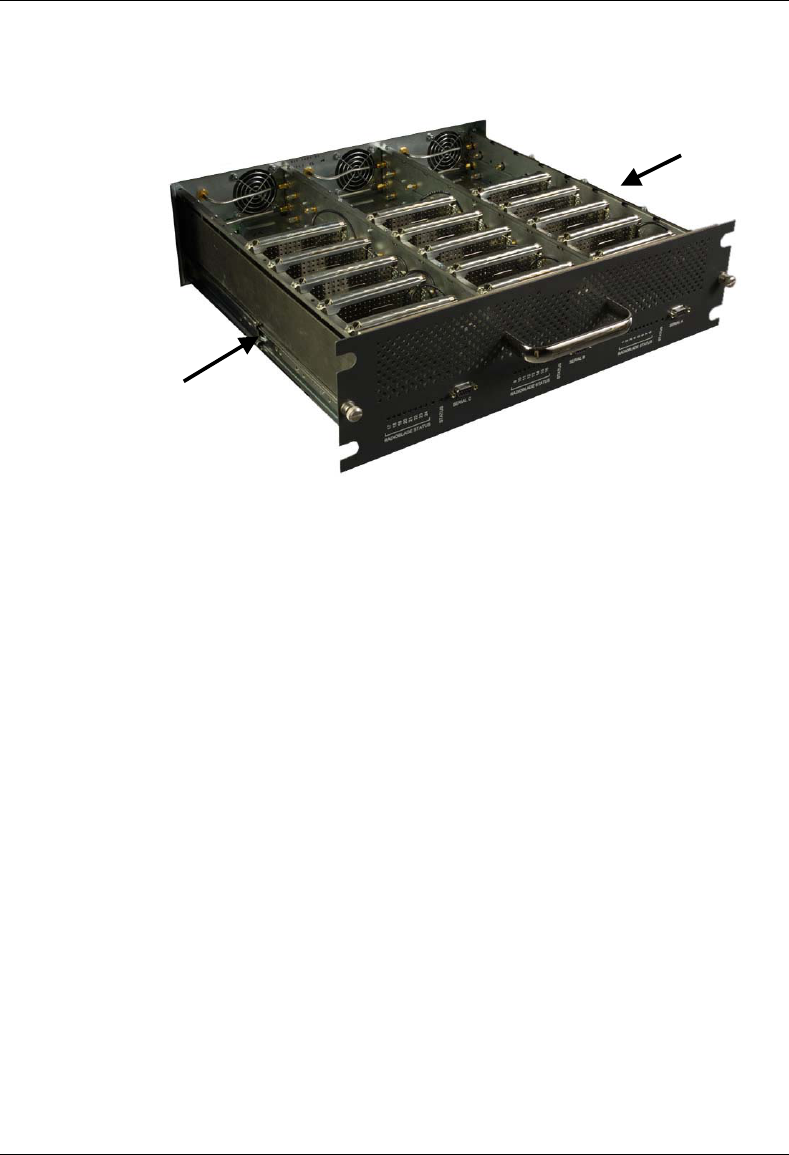
MC-Series System Installation & Testing
Scheduled and Unscheduled Maintenance
110 RadioFrame Networks, Inc.
9 In System Manager, refresh the RBS Status page until the RadioBlade icon status bar
changes from red (not present) to yellow (present and locked). This will take approximately
three minutes.
10 Unlock the RadioBlade.
On the RadioBlade Statistics page, the State of the RadioBlade will change from 2 (locked) to 11
(unlocked).
7.9.4.2 Multi Ch 900 RB
TBD
7.9.4.3 Multi Ch 800 RB
TBD
7.9.5 Power Distribution Unit
The Power Distribution Unit (PDU) receives DC input and supplies power via dedicated circuit
breakers to each component in the MC-Series System. Each of the thirteen breakers has a three-
position switch: ON, OFF or TRIPPED. The single alarm output connected to each breaker is
normally closed, and goes open when a breaker is tripped.
locking arm
locking arm
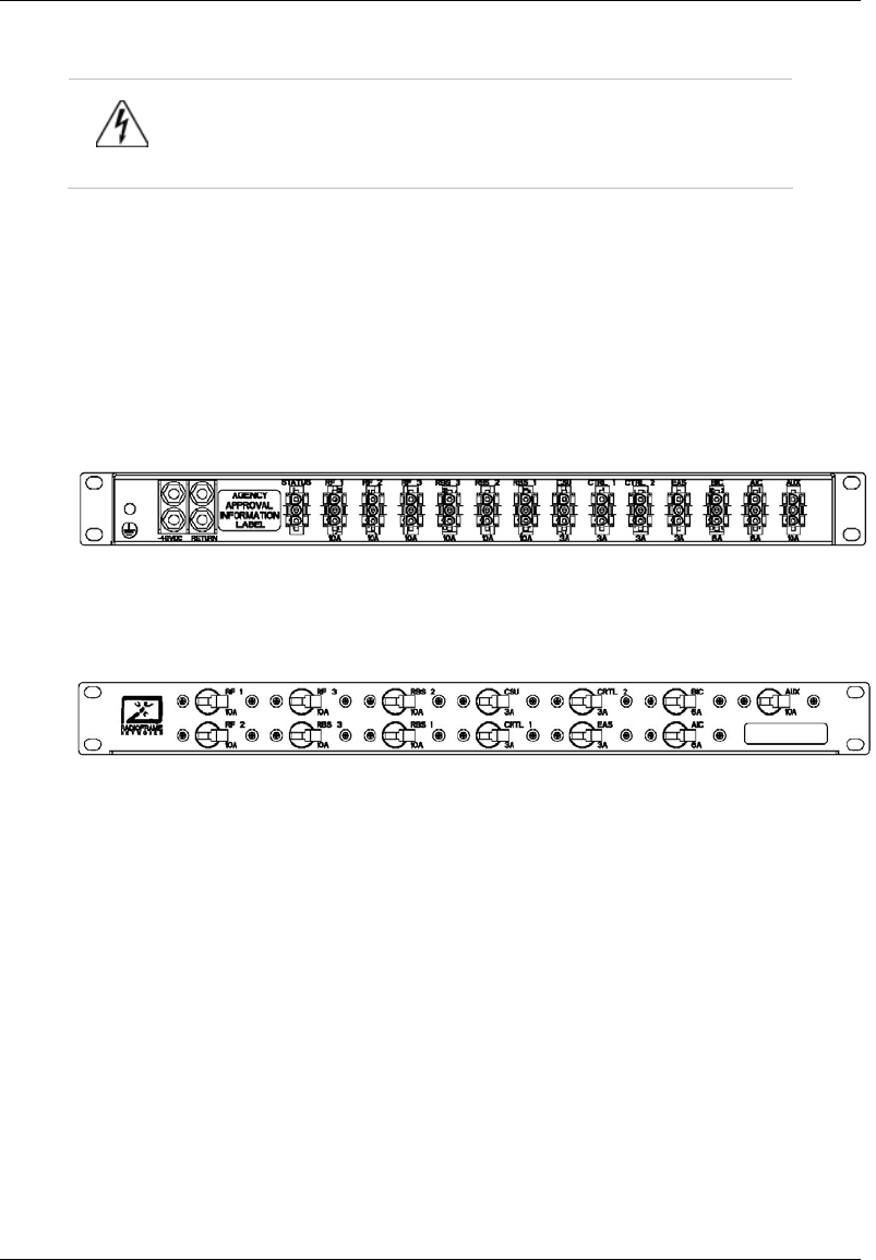
MC-Series System Installation & Testing
Scheduled and Unscheduled Maintenance
RadioFrame Networks, Inc. 111
Warning!
Verify that all breakers in the PDU are in the OFF position prior to proceeding.
Leave them in the OFF position until instructed otherwise.
1 Verify that all breakers are in the ‘off’ position on the front of the PDU.
2 Follow the power supply and battery manufacturer's installation and maintenance
documentation to remove power from the PDU.
3 Disconnect the powerplant from the PDU using the two lugs.
4 Remove all power connections from the back of the PDU.
5 Remove the 4 front mounting screws from the front of the PDU, and remove the PDU from
the rack, and then package it for shipment.
Figure 38 PDU Rear view
Figure 39 PDU rear view
6 Mount the replacement PDU.
While supporting the PDU, slide it into the cabinet mounting position. Secure the PDU to the
cabinet mounting rails using the four mounting screws provided with the unit. Tighten the
screws to 4.5 Nm (40 in-lb).
7 Reconnect all power connections to the back of the PDU.
8 Follow Power supply and battery manufacturer's installation and maintenance documentation
to install power to PDU.
9 Using the breakers on the PDU, turn up the BIC, AIC, and RBS 1 (and RBS 2 and RBS 3 if
present), and then verify that the components are operational before proceeding.
Wait approximately 3 minutes for the following indicators:
• RBS: The STATUS LED for each group will light green in this order: A, B, and then C.

MC-Series System Installation & Testing
Scheduled and Unscheduled Maintenance
112 RadioFrame Networks, Inc.
• RBS: The RADIOBLADE STATUS LEDs will light red and then green for each present
RadioBlade. If no RB is present, the LED will not light. To verify the contents of the RBS,
pull out the shelf (powering off is not required) and inspect the RadioBlades and their
respective status LEDs. Reinsert the RBS. To do this, press up on one side rail locking
arm and press down on the other side rail locking arm, and then push the unit into the
rack (see the following illustration).
• BIC CRIC and AIC CRIC: The POWER and STATUS LEDs will light red and then green.
All other BIC and AIC card LEDs will light green.
10 Using the breaker on the PDU, turn up each RF Shelf and then verify that each RF Shelf is
operational before proceeding. The POWER and ALARM LEDs on the front of the RF Shelf
will light green.
11 Complete the procedures in sections 5.4, 5.5 and 5.6.
7.10 TOR Tx Measurement Procedure
1 Measure the output from the Tx 1, Tx 2, and Tx 3 connectors at the top of the cabinet using a
digital RF power meter.
NOTE: Test only the Tx 1 connector in an omni configuration.
2 Adjust the power budget of the DAS using the variable TX ATTENUATION knobs on the front
panel of each RF Shelf.
The outside knob adjusts in 10 dB increments, and the inside knob adjusts in 1 dB
increments, up to 50 db maximum.
NOTE: The variable attenuators only impact the RF downlink. If large values of attenuation
are required, consider adding external attenuation to the uplink of the Rx port to maintain link
balance.
3 Make sure the Nextel-provided coax jumpers have been swept.
4 Connect the jumpers between the TOR Tx 1 and DAS RF IN, and then connect the jumpers
between the TOR Rx 1 and DAS RF OUT.
In a sectored MC-Series System, connect the jumpers to the DAS commensurate with the
sector coverage area and hub locations per Nextel design.
5 Measure the output at the DAS remote unit(s) to verify power budget accuracy.
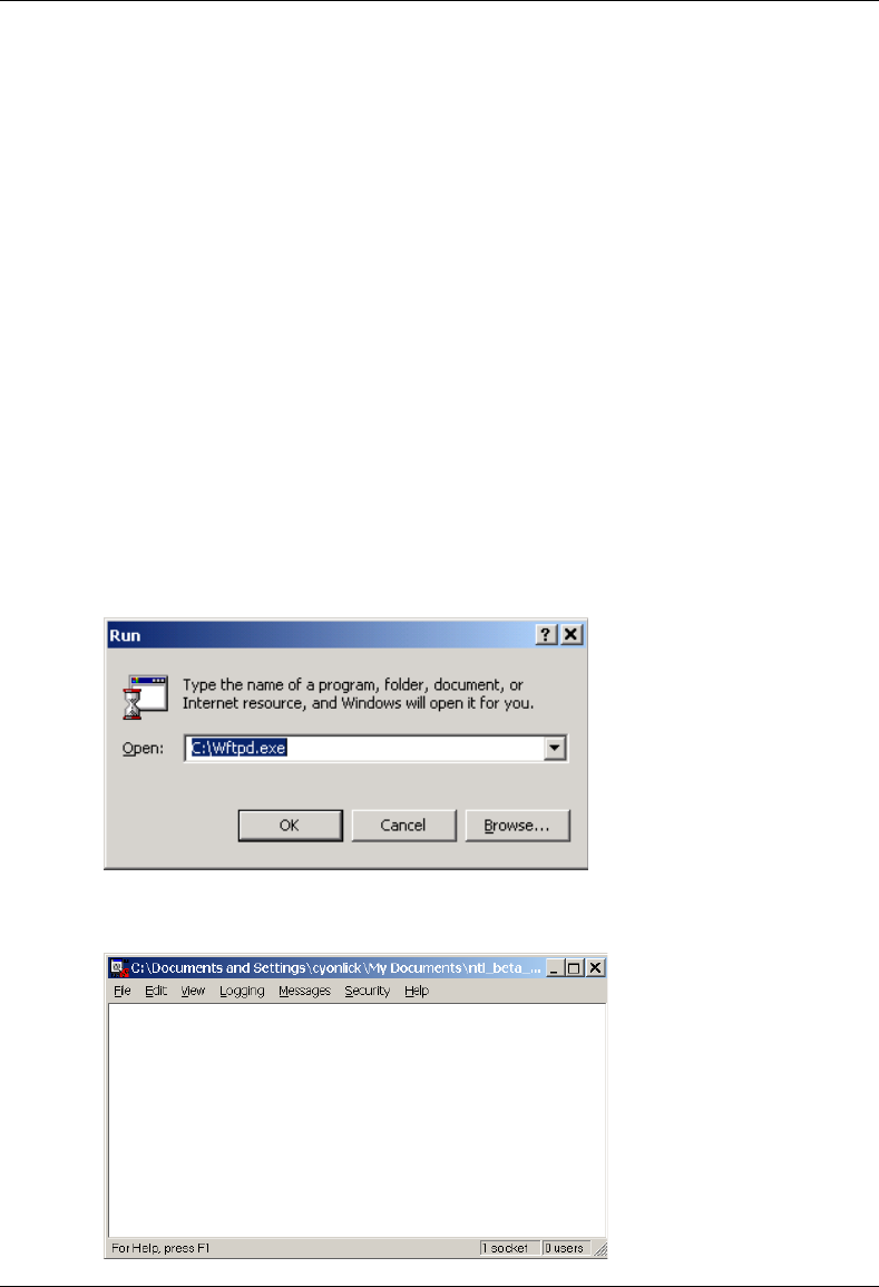
MC-Series System Installation & Testing
System Configuration Changes
RadioFrame Networks, Inc. 113
8 System Configuration Changes
8.1 Upgrading MC-Series System Software
The MC-Series System is shipped with the latest software installed. With each new software
release, RadioFrame Networks provides its customers with the new software and accompanying
information in the RadioFrame Networks Customer Release Notes. The following procedures
describe how to upgrade MC-Series System software. System Manager contains two separate
partitions in which to install software: active and inactive. This provides the means to revert back
to a previous version of system software if required.
8.1.1 Download MC-Series System Software to the Laptop Computer
1 Download RFN_XXX, a self-extracting zip file from:
http://www.radioframenetworks.com/support/nextel/sw
Install/extract the zip file directly into the C:/ drive on the laptop. This also installs an FTP (file
transfer protocol) server application (Wftpd.exe) and three directories: docs, platform, and
iden. If Wftpd.exe is already installed on the laptop, skip to step .
2 Open FTP Server – START menu x RUN x C:\Wftpd.exe.
The following configuration is for Wfptd:
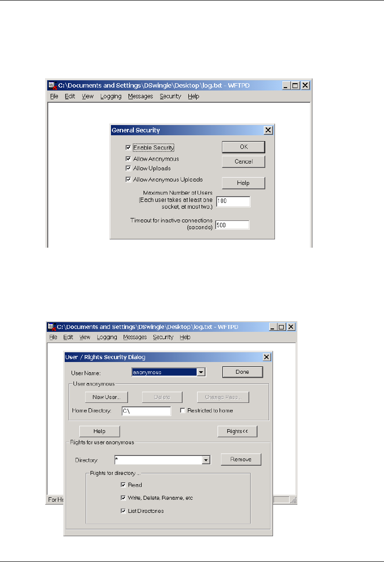
MC-Series System Installation & Testing
System Configuration Changes
114 RadioFrame Networks, Inc.
3 From the Security menu, select General, configure the General Security page as shown,
and then select OK.
4 From the Security menu, select User/rights, and for User Name select anonymous from
the drop down menu, and then select the Rights<< button and verify that the settings are the
same as shown below.
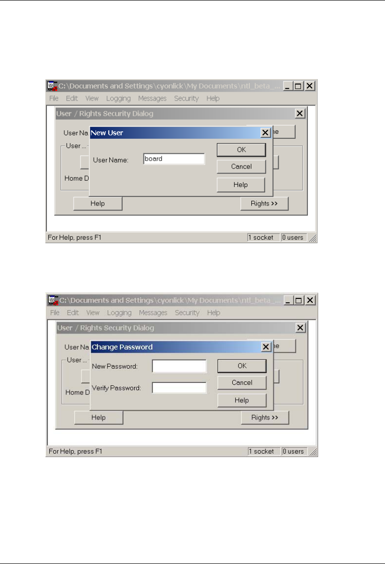
MC-Series System Installation & Testing
System Configuration Changes
RadioFrame Networks, Inc. 115
5 Select the New User… button, and then for User Name type board in the text box, and then
select OK.
6 For New Password type wind, then retype wind in the Verify Password text box, and then
select OK.
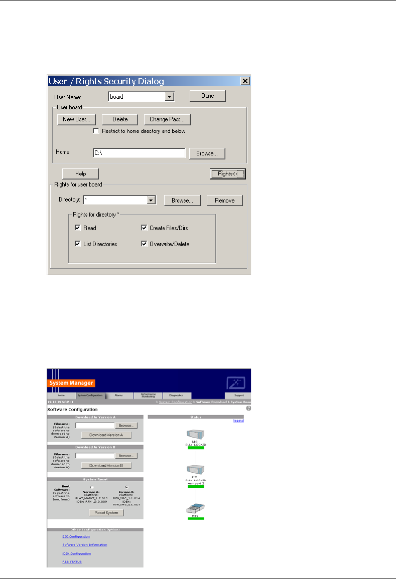
MC-Series System Installation & Testing
System Configuration Changes
116 RadioFrame Networks, Inc.
7 The User/Rights Security dialog box reappears, and the User Name is now set to board.
Select the Rights button and verify that the settings are the same as shown below, and then
select Done.
8.1.2 Install the MC-Series System Software Update
1 Connect the laptop to the MC-Series System, start System Manager, and log in (for complete
instructions, refer to section 5.4 System Setup).
2 Select the Software Download & System Reset link on the System Configuration page.
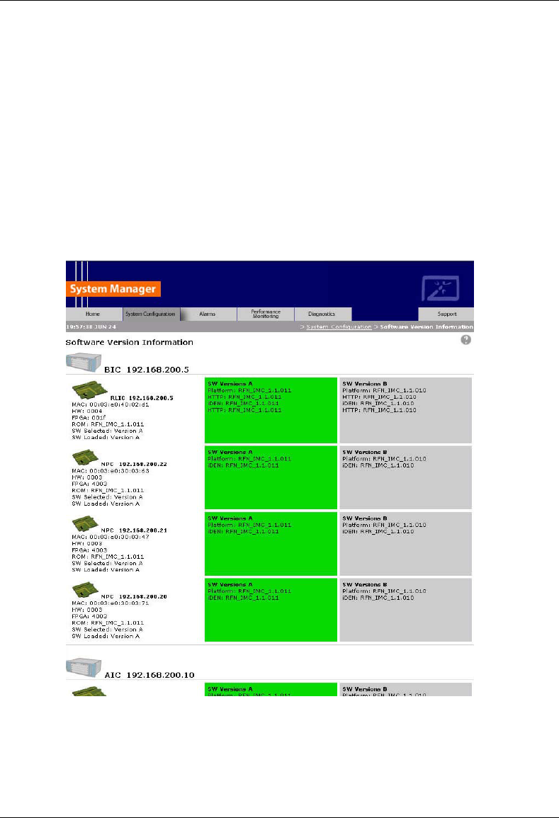
MC-Series System Installation & Testing
System Configuration Changes
RadioFrame Networks, Inc. 117
3 Download platform_download.txt to the inactive partition.
The inactive partition is the one that is not selected under System Reset (A or B). Browse for
the file in the text box of the inactive partition, A or B, and then select the Download to
Version… button.
4 Download iden_download.txt to the inactive partition.
5 Under System Reset, select the inactive partition and then select the Reset System button.
Wait for the download to complete successfully, which may take several minutes.
8.1.3 Verify the Software Download
1 Select the Software Version Information link on the Software Configuration page
2 Review the SW Versions A and SW Versions B to make sure the latest software is loaded in
the correct partition.
3 Verify that the SW Selected and SW Loaded for each component in the system is correct.

MC-Series System Installation & Testing
System Configuration Changes
118 RadioFrame Networks, Inc.
8.1.4 Reverting to the previous version of software
Revert to a previous version of MC-Series System software only if the upgrade fails.
1 Select the Software Download & System Reset on the System Configuration page.
2 Under System Reset, select the inactive partition to revert to the previously loaded version of
software.
3 Select the Reset System button.
This reboot will take several minutes to complete. Wait for the system to come back, and then
refresh the page or reopen the web browser to force the page to update.
8.2 Adding or Removing RadioBlades
The MC-Series system supports hot swapping of RadioBlade transceivers. This means that
replacement of a RadioBlade can be done while the system is live and does not require a system
reset. When RadioBlades are hot swapped no alarm is generated. Rather, an RB lock and unlock
event is placed in the System Manager Event log.
Each RadioBlade is shipped wrapped in antistatic packaging, along with a lockdown strap and
screw for securing the RB in the RadioBlade Shelf (RBS).
Follow the procedure in section 7.7.1. Replacing an iDEN 2-Port RadioBlade Transceiver to add
or remove a RadioBlade.
8.3 Adding a Sector
To add a sector to the MC-Series System, connect and power RF Shelf 2 or RF Shelf 3. To add
one sector, connect and power RF Shelf 2. To add two sectors, connect and power RF Shelf 2
and RF Shelf 3. Refer to Appendix C Cabling Diagrams: 3-Sector Configuration.
1 Have the site configuration available.
2 In System Manager, display the iDEN Configuration page, and change the cabinet/positions
(and quad BRs or adjacent channel assignments) as required for the new configuration (refer
to the site datafill).
3 Power down all RFN equipment in the following order using circuit breakers on the PDU:
• BIC
• AIC
• RBS 1 (RBS 2 and RBS 3 if present)
• RF Shelf 1 (if present and powered, RF Shelf 2 or RF Shelf 3)
4 If a new RF shelf must be installed for the new configuration, mount it now.
While supporting the RF shelf, slide it into the cabinet mounting position. Secure the RF shelf
to the cabinet mounting rails using the four mounting screws provided with the unit. Tighten
the screws to 4.5 Nm (40 in-lb).
MC-Series System Installation & Testing
System Configuration Changes
RadioFrame Networks, Inc. 119
5 Remove the following terminations from the rear of each RF shelf to be added to the
configuration:
• RF Shelf 2:Tx IN B and Rx OUT B
• RF Shelf 3:Tx IN C and Rx OUT C
6 Reconnect the following RF cables:
Index Part Number From To Type
RF_2 820-0611-20 RF Shelf 2: Tx IN B RBS 1: Tx B RF cable
RF_5 820-0611-20 RF Shelf 2: Rx OUT B RBS 1: Rx B RF cable
RF_3 820-0611-20 RF Shelf 3: Tx IN C RBS 1: Tx C RF cable
RF_6 820-0611-20 RF Shelf 3: Rx OUT C RBS 1: Rx C RF cable
7 Reconnect terminations to RF Shelf 1:
Index Part Number To Notes
T2 820-0609-00 RF Shelf 1: Tx IN B If adding RF Shelf 2
T4 820-0609-00 RF Shelf 1: Rx OUT B If adding RF Shelf 2
T3 820-0609-00 RF Shelf 1: Tx IN C If adding RF Shelf 3
T5 820-0609-00 RF Shelf 1: Rx OUT C If adding RF Shelf 3
8 Remove the dust caps (RFN P/N: 546-0005-00) from cables RF_15 and RF_16 (RF Shelf 2)
and/or RF_21, and RF_22 (RF Shelf 3).
9 Remove the dust caps (RFN P/N: 546-0003-00) from TOR Tx 2 and Rx 2 (RF Shelf 2) and/or
TOR Tx 3 and Rx 3 (RF Shelf 3).
10 Reconnect the following RF cables:
Index Part Number From To Type
RF_15 820-0610-30 RF Shelf 2: TX OUT TOR: Tx 2 RF cable
RF_16 820-0610-30 RF Shelf 2: RX IN TOR: Rx 2 RF cable
RF_21 820-0610-30 RF Shelf 3: TX OUT TOR: Tx 3 RF cable
RF_22 820-0610-30 RF Shelf 3: RX IN TOR: Rx 3 RF cable
11 If the new configuration is two sectors only, RF Shelf 3 remains in the rack and must remain
unpowered.
12 Push the new datafill load to the iSC.
13 Using the breakers on the PDU, turn up the BIC, AIC, and RBS 1 (RBS 2 and RBS 3 if
present), and then verify that the components are operational before proceeding.
Wait approximately 3 minutes for the following indicators:
• RBS: The STATUS LED for each group will light green in this order: A, B, and then C.
• RBS: The RADIOBLADE STATUS LEDs will light red and then green for each present
RadioBlade. If no RB is present, the LED will not light. To verify the contents of the RBS,
pull out the shelf (powering off is not required) and inspect the RadioBlades and their

MC-Series System Installation & Testing
System Configuration Changes
120 RadioFrame Networks, Inc.
respective status LEDs. Reinsert the RBS. To do this, press up on one side rail locking
arm and press down on the other side rail locking arm, and then push the unit into the
rack (see the following illustration).
• BIC CRIC and AIC CRIC: The POWER and STATUS LEDs will light red and then green.
All other BIC and AIC card LEDs will light green.
14 Using the breaker on the PDU, turn up RF Shelf 1 and RF Shelf 2.
Do not turn up RF Shelf 3. Verify that RF Shelf 1 and RF Shelf 2 are operational before
proceeding.
The POWER and ALARM LEDs on the front of each RF shelf will light green.
15 Complete the procedure in section 7.8 TOR Tx Measurement Procedure.
8.4 Removing a Sector
To remove a sector from the MC-Series System, disconnect an RF shelf. To remove one sector,
disconnect RF Shelf 3. To remove two sectors, disconnect both RF Shelf 2 and RF Shelf 3. Refer
to Appendix C Cabling Diagrams: 3-Sector Configuration.
1 Have the site configuration available.
2 In System Manager, display the iDEN Configuration page, and change the cabinets and
positions (and quad BRs or adjacent channel assignments) as required for the new
configuration (refer to the site datafill).
3 Power down all RFN equipment in the following order using circuit breakers on the PDU:
• BIC
• AIC
• RBS 1 (RBS 2 and RBS 3 if present)
• RF shelf 1, 2, and 3
4 Remove the following terminations from RF Shelf 1:
• RF Shelf 2: Tx IN B and Rx OUT B
• RF Shelf 3: Tx IN C and Rx OUT C
5 Reconnect terminations to:
• RF Shelf 2: Tx IN B and Rx OUT B
• RF Shelf 3: Tx IN C and Rx OUT C
6 Reconnect the following RF cables to RF Shelf 1:
Index Part Number From To Type
RF_2 820-0611-20 RF Shelf 2: Tx IN B RF Shelf 1: Tx IN B RF cable
RF_5 820-0611-20 RF Shelf 2: Rx OUT B RF Shelf 1: Rx OUT B RF cable
RF_3 820-0611-20 RF Shelf 3: Tx IN C RF Shelf 1: Tx IN C RF cable
RF_6 820-0611-20 RF Shelf 3: Rx OUT C RF Shelf 1: Rx OUT C RF cable

MC-Series System Installation & Testing
System Configuration Changes
RadioFrame Networks, Inc. 121
7 Reconnect terminations to:
• RF Shelf 2: Tx IN B and Rx OUT B
• RF Shelf 3: Tx IN C and Rx OUT C
8 The disconnected RF shelf (or shelves) remain in the rack and must remain unpowered.
The following cables may remain as long the RF shelf remains unpowered:
Index Part Number From To Type
AL_2 820-0607-00 RF Shelf 2: ALARM RBS: ALARM INPUT B serial
RF_15 820-0610-30 RF Shelf 2: TX OUT TOR: Tx 2 RF cable
RF_16 820-0610-30 RF Shelf 2: RX IN TOR: Rx 2 RF cable
AL_3 820-0607-00 RF Shelf 3: ALARM RBS: ALARM INPUT C serial
RF_21 820-0610-30 RF Shelf 3: TX OUT TOR: Tx 3 RF cable
RF_22 820-0610-30 RF Shelf 3: RX IN TOR: Rx 3 RF cable
9 Place dust caps (RFN P/N: 546-0005-00) on cables (end not going to TOR):
• RF Shelf 2: RF_15 and RF_16
• RF Shelf 3: RF_21 and RF_22
10 Place dust caps (RFN P/N: 546-0003-00) on the TOR:
• RF Shelf 2: Tx 2 and Rx 2
• RF Shelf 3: Tx 3 and Rx 3
11 Push the new datafill load to the iSC.
12 Using the breakers on the PDU, turn up the BIC, AIC, and RBS 1 (RBS 2 and RBS 3 if
present), and then verify that the components are operational before proceeding.
• RBS: The STATUS LED for each group will light green in this order: A, B, and then C.
• RBS: The RADIOBLADE STATUS LEDs will light red and then green for each present
RadioBlade. If no RB is present, the LED will not light. To verify the contents of the RBS,
pull out the shelf (powering off is not required) and inspect the RadioBlades and their
respective status LEDs. Reinsert the RBS. To do this, press up on one side rail locking
arm and press down on the other side rail locking arm, and then push the unit into the
rack (see the following illustration).
• BIC CRIC and AIC CRIC: The POWER and STATUS LEDs will light red and then green.
All other BIC and AIC card LEDs will light green.
13 Using the breakers on the PDU, turn up RF Shelf 1 only. Do not turn up RF Shelf 2 and RF
Shelf 3 unless part of the new configuration. Verify that RF Shelf 1 is operational before
proceeding.
The POWER and ALARM LEDs on the front of each RF Shelf will light green.

MC-Series System Installation & Testing
System Configuration Changes
122 RadioFrame Networks, Inc.
8.5 Parts and Suppliers
This section contains recommended part numbers (P/N) and manufacturers of various hardware,
tools, and equipment used during the installation, operations, and maintenance of the MC-Series
System.
8.5.1 Rack screws
8.5.2 Anchors
Hilti
8.5.3 Cables and Connectors
8.5.4 Matching Terminals for PDU and Ground
Select from the following list of termination lugs (listed is the smallest packaging size available):
use two when connecting the powerplant to the PDU, and one when connecting the PDU ground
to the top of the bus bar.
1. LCD2-14A-Q 2 AWG STRAIT (QTY: 25 per pk.)
2. LCD2-14AF-Q 6 AWG STRAIT (25/pk)
3. LCD6-14A-L 2 AWG RIGHT ANGLE (50/pk)
4. LCD6-14AF-L 6 AWG RIGHT ANGLE (50/pk)
5. Crimp Tool needed: CT-1700
8.5.5 GPS surge arrestor
PolyPhaser RGT Broadband DC Pass Protector

MC-Series System Installation & Testing
System Configuration Changes
RadioFrame Networks, Inc. 123
Current: 10Adc
Insertion Loss: ≤ 0.25dB
Freq. Range: 0-2400MHz
Mounting: Bulkhead
Operating Voltage: +/-60 Volts
Protected Side Connector: N Female 50Ω
Replaceable Gas Tube: Yes
Surge Side Connector: N Female 50Ω
Throughput Energy: ≤ 2283µJ for 3kA @ 8/20µs Waveform
Turn-On Voltage: +/-180 Volts
Unit Impedance: 50Ω
Voltage Standing Wave Ratio: 1.28 : 1
Weatherized: Bellcore #TA-NWT-000487 Procedure 4.11,
Wind Driven (120 mph) Rain Intrusion.
8.5.6 RF Feed Throughs (N-type connectors)
514-0001-99 Terminator, N-M w/ chain 2W 6GHz, 18db max VSWR @ 6GHz
S.M Electronics P/N: STN0610C
8.6 Available Field Replaceable Units (FRUs)
The MC-Series System has been designed so that Field Repairable Units (FRUs) can be
replaced to restore normal system operation as quickly as possible. The following table lists
RadioFrame Networks FRUs. For equipment not supplied by RadioFrame Networks, follow
standard Nextel policies and procedures for FRU replacement. For more information, refer to
section 1.4.3 Field Replaceable Unit (FRU) Policy.
Table 7 MC-Series System FRUs
P/N Description
176-0840-xx 800 MHz MC Series iDEN 2-Port RadioBlade (RB) Transceiver
176-0870-xx 800 MHz RF Shelf
176-0535-xx RadioBlade Transceiver Shelf (RBS)

MC-Series System Installation & Testing
System Configuration Changes
124 RadioFrame Networks, Inc.
P/N Description
176-0800-xx MC-15 Airlink Interface Chassis (AIC)
176-0900-xx MC-15 BTS Interface Chassis (BIC)
176-7570-xx Base Processing Card (BPC)
176-7550-xx Base Processing Card (BPC) with SPAM
176-7540-xx Common RadioFrame Interface Card (CRIC)
176-7562-xx Ethernet Rear Transition Module (ERTM)
176-7510-xx Signal Processing Array Module (SPAM)
176-0820-xx CRTC
176-7502-xx 4U Chassis
176-0600-xx PDU
176-1219-xx Fan Tray w/Fans for 4U Chassis
176-0011-xx Fan for RBS, RF Shelf, AIC & BIC
8.7 Spares
Nextel will purchase spare parts for the MC-Series System on an as-needed basis from
RadioFrame Networks. At minimum, RadioFrame Networks will make available for purchase by
Nextel, and Nextel will purchase, spare MC-Series System parts and components in the
quantities set forth below:
Figure 40 1% onsite sparing of iDEN 2-port and multi-Channel RadioBlade transceivers
(one minimum of each per site)
Figure 41 2% regional sparing of the following (one minimum per region):
iDEN 2-port RadioBlade Transceiver
iDEN Multi-Channel RadioBlade
RF Shelf
RBS
AIC
BIC
Unless otherwise agreed by RadioFrame Networks and Nextel, RadioFrame Networks will act as
Nextel’s depot for Regional Spares purchased by Nextel. Such Regional Spares will be owned by
Nextel and will be shipped to the U.S. location designated by Nextel within one (1) business day
following Nextel’s request. Such spares will be shipped at Nextel’s expense via overnight courier
or other shipping method requested by Nextel.

MC-Series System Installation & Testing
Appendix A: Glossary
RadioFrame Networks, Inc. 125
A. Glossary
Acronym Term Description
10Base2
10Base2 is also known as Thin Ethernet. 10Base2 cables support
transmission speeds up to 10 Mbits/second. The maximum distance per
segment is 185 meters.
10BaseT
10BaseT is the most common form of Ethernet cabling. The cable is
thinner and more flexible than the coaxial cable used for the 10Base2
standard. 10BaseT is also known as unshielded twisted-pair (UTP).
10BaseT cables support speeds up to 10 Mbps. The maximum distance
per segment is 500 meters.
AIC Airlink Interface Chassis The central baseband processing unit for the MC-Series System,
providing Rx/Tx airlink traffic to/from RBSs.
BIC BTS Interface Chassis
The central network processing unit for the MC-Series System. Also
central management entity for managing configuration and User
Information.
BPC BTS Processing Cards Interface to the BIC CRIC for the bi-directional transfer of voice I and Q
samples to/from RBS.
BPC+SPAM BPC+SPAM Interface to the AIC CRIC for the control of RBS components and the
transfer of voice I/Q samples to/from RBS.
CRIC Common RadioFrame
Interface Card
In the BIC, provides Ethernet switching to/from the AIC, and serves as
the primary controller of the BPCs. In the AIC, provides Ethernet
switching to/from the AIC and the RBS, and serves as the primary
controller of the BPC+SPAMs.
CRTC Coax-to-RJ45
Transceiver Card
Provides 10base2 (coaxial television) conversion to 10baseT (RJ45).
This card connects the 10base2 cable coming from the iSC to Port 1 of
the BIC.
CSU Channel Service Unit The CSU provides the T1 connection between the iSC-3 and the
telephone company that provides the T1 line.
EAS Environmental Alarm
System
The EAS provides a central location for site alarm signal processing.
The EAS monitors environmental conditions of the site, including power,
smoke alarms, and intrusion alarms.
EIA Electronic Industries
Alliance The EIA organization establishes electronic interface standards.
ERTM Ethernet Rear Transition
Module
In the BIC, provides timing and data to the AIC. In the AIC, provides
timing and data to the RBS.
ESD Electrostatic Discharge
The dissipation of electricity, commonly known as a shock. ESD can
destroy semiconductor products, even when the discharge is too small
to be felt.
FRU Field Replaceable Unit
Any unit (module, board, or card) that can be “hot-swapped”, that is,
replaced with another unit while the power is connected to the item
housing the unit.
GPS Global Positioning
System
A system that uses geostationary satellites to triangulate the position of
a GPS receiver located on earth.
iDEN integrated Digital
Enhanced Network
Motorola's proprietary digital technology that combines the capabilities
of a standard analog dispatch system with that of a cellular interconnect
system. iDEN uses an advanced proprietary modulation technology
consisting of a speech compression scheme enabling three or six
communication paths over a single 25 kHz RF channel.

MC-Series System Installation & Testing
Appendix A: Glossary
126 RadioFrame Networks, Inc.
Acronym Term Description
iSC integrated Site
Controller
The controller and communications gateway between the MC-Series
System and the Nextel central network. The iSC is required for all
RadioFrame Networks iDEN installations.
MC-Series MC-Series System
Digital Communication System for indoor wireless device users. The
MC-Series System consists of several components: BIC, AIC, RBS and
iDEN RadioBlades.
MIB Management
Information Base A database of network performance information.
PDU Power Distribution Unit The panel used for distributing power to the units within the cabinet.
RB RadioBlade Provides the airlink interface for the iDEN standard.
RFN RadioFrame Networks Equipment designer and manufacturer of MC-Series System
equipment.
RFS RadioFrame System See MC-Series.
RSSI Received Signal
Strength Indication Strength of the received call signal, in dBm.
SELV Safety Extra-Low
Voltage
A secondary electrical circuit designed so that under normal and signal
fault conditions, its voltages do not exceed a safe-value.
SPAM Signal Processing Array
Module
A connectorized card that plugs into the BPC to provide digital signal
processing resources.
SQE Signal Quality Estimate An estimate of signal quality, based on the received signal strength and
quality.
T1 Digital Transmission
Rate 1
T1—A North American leased-line connection capable of carrying 1.544
megabits of data per second (Mbps). T1 lines are commonly used to
connect networks, ISPs and others to the Internet.
An E-1 line is the European equivalent to the North American T1.
However, an E-1 line carries information at the rate of 2.048 Mbps
instead of the 1.544 Mbps of a T1.
T568B Wiring standard for MC-Series System CAT-5 cables. Denotes a
specific order of the CAT-5 wires leading into the RJ-45 connector.
TAC Technical Assistance
Center
RadioFrame Networks customer support is available 24x7x365:
1-800-328-0847
TOR Top of Rack Used to refer to the top of the rack.

MC-Series System Installation & Testing
Appendix B: Default IP Addresses
RadioFrame Networks, Inc. 127
B. Default IP Addresses
The following table lists default IP addresses for RadioFrame Networks chassis boards, and the
default IP address required for logging in to the MC-Series System.
Device Card Type Chassis Slot/Port IP Address
Laptop N/A N/A 169. 254.200. 5
BIC CRIC Slot 0 192.168.200. 5
BPC Slot 1 192.168.200. 6
BPC Slot 2 192.168.200. 7
BPC Slot 3 192.168.200. 8
AIC CRIC Slot 0 192.168.200. 20
APC Slot 1 192.168.200. 21
APC Slot 2 192.168.200. 22
APC Slot 3 192.168.200. 23
RBS backplane Group 1 192.168.200. 98
Group 2 192.168.200. 99
Group 3 192.168.200. 100

MC-Series System Installation & Testing
Appendix C: Cabling Diagrams: 3-Sector Configuration
128 RadioFrame Networks, Inc.
C. Cabling Diagrams: 3-Sector Configuration
The following table is the index to the following three figures that show cabling for the standard
3-sector MC-Series System.
Power Part Number From To Notes
P_1 820-0616-10 PDU: RF 1 RF Shelf 1 Power
P_2 820-0616-10 PDU: RF 2 RF Shelf 2 Power
P_3 820-0616-20 PDU: RF 3 RF Shelf 3 Power
P_4 820-0616-30 PDU: RBS 3 RBS 3 Power: connected to PDU only
P_5 820-0616-30 PDU: RBS 2 RBS 2 Power: connected to PDU only
P_6 820-0616-50 PDU: RBS 1 RBS 1 Power
P_7 820-0615-50 PDU: CSU CSU Power
P_8 820-0613-50 PDU: CTRL 1 ISC 1 Power: primary iSC
P_9 820-0613-50 PDU: CTRL 2 ISC 2 Power: secondary iSC
P_10 820-0616-50 PDU: EAS EAS Power
P_11 820-0614-00 PDU: BIC BIC Power
P_12 820-0614-10 PDU: AIC AIC Power
P_13 PDU: AUX Power: left unconnected
P_14 102-0011-04 RF Shelf 1: Fan 1 RF Shelf 1: FAN Power
P_15 102-0011-04 RF Shelf 1: Fan 2 RF Shelf 1: FAN Power
P_16 102-0011-04 RF Shelf 2: Fan 1 RF Shelf 2: FAN Power
P_17 102-0011-04 RF Shelf 2: Fan 2 RF Shelf 2: FAN Power
P_18 102-0011-04 RF Shelf 3: Fan 1 RF Shelf 3: FAN Power
P_19 102-0011-04 RF Shelf 3: Fan 2 RF Shelf 3: FAN Power
P_20 102-0011-04 RBS 1: Fan RBS 1: FAN A Power
P_21 102-0011-04 RBS 1: Fan RBS 1: FAN B Power
P_22 102-0011-04 RBS 1: Fan RBS 1: FAN C Power
Ground Part Number From To Notes
G_1 TBD TOR GND BAR
G_2 820-0609-00 PDU GND BAR
G_3 820-0609-00 RF Shelf 1 GND BAR
G_4 820-0609-00 RF Shelf 2 GND BAR
G_5 820-0609-00 RF Shelf 3 GND BAR
G_6 820-0609-00 RBS 3 GND BAR connected only to GND BAR
G_7 820-0609-00 RBS 2 GND BAR connected only to GND BAR
G_8 820-0609-00 RBS 1 GND BAR
G_9 820-0609-10 CSU GND BAR
G_10 820-0609-10 ISC1 GND BAR
G_11 820-0609-10 ISC2 GND BAR
G_12 820-0609-10 EAS GND BAR
G_13 820-0609-00 BIC GND BAR
G_14 820-0609-00 AIC GND BAR

MC-Series System Installation & Testing
Appendix C: Cabling Diagrams: 3-Sector Configuration
RadioFrame Networks, Inc. 129
RF Part Number From To Notes
GPS_1 820-0620-00 ISC 1: GPS TOR: GPS 1 RF CABLE
GPS_2 820-0620-00 ISC 2: GPS TOR: GPS 2 RF CABLE
RF_1 820-0611-20 RF Shelf 1: Tx IN A RBS 1: Tx A RF CABLE
RF_2 820-0611-20 RF Shelf 2: Tx IN B RBS 1: Tx B RF CABLE
RF_3 820-0611-20 RF Shelf 3: Tx IN C RBS 1: Tx C RF CABLE
RF_4 820-0611-20 RF Shelf 1: Rx OUT A RBS 1: Rx A RF CABLE
RF_5 820-0611-20 RF Shelf 2: Rx OUT B RBS 1: Rx B RF CABLE
RF_6 820-0611-20 RF Shelf 3: Rx OUT C RBS 1: Rx C RF CABLE
RF_7 820-0600-10 RF Shelf 1: TX IN RF Shelf 1: PA OUT RF CABLE
RF_8 820-0600-00 RF Shelf 1: TX TEST PORT RF Shelf 1: Tx TEST RF CABLE
RF_9 820-0610-30 RF Shelf 1: TX OUT TOR: Tx 1 RF CABLE
RF_10 820-0610-30 RF Shelf 1: RX IN TOR: Rx 1 RF CABLE
RF_11 820-0600-10 RF Shelf 1: RX OUT RF Shelf 1: LNA IN RF CABLE
RF_12 820-0600-20 RF Shelf 1: RX OUT DIV RF Shelf 1: LNA DIV IN RF CABLE
RF_13 820-0600-10 RF Shelf 2: TX IN RF Shelf 2: PA OUT RF CABLE
RF_14 820-0600-00 RF Shelf 2: TX TEST PORT RF Shelf 2: Tx TEST RF CABLE
RF_15 820-0610-30 RF Shelf 2: TX OUT TOR: Tx 2 RF CABLE
RF_16 820-0610-30 RF Shelf 2: RX IN TOR: Rx 2 RF CABLE
RF_17 820-0600-10 RF Shelf 2: RX OUT RF Shelf 2: LNA IN RF CABLE
RF_18 820-0600-20 RF Shelf 2: RX OUT DIV RF Shelf 2: LNA DIV IN RF CABLE
RF_19 820-0600-10 RF Shelf 3: TX IN RF Shelf 3: PA OUT RF CABLE
RF_20 820-0600-00 RF Shelf 3: TX TEST PORT RF Shelf 3: Tx TEST RF CABLE
RF_21 820-0610-30 RF Shelf 3: TX OUT TOR: Tx 3 RF CABLE
RF_22 820-0610-30 RF Shelf 3: RX IN TOR: Rx 3 RF CABLE
RF_23 820-0600-10 RF Shelf 3: RX OUT RF Shelf 3: LNA IN RF CABLE
RF_24 820-0600-20 RF Shelf 3: RX OUT DIV RF Shelf 3: LNA DIV IN RF CABLE
DIV_1 820-0610-30 TOR: DIV 1 RF Shelf 1 connected only to TOR
DIV_2 820-0610-30 TOR: DIV 2 RF Shelf 2 connected only to TOR
DIV_3 820-0610-30 TOR: DIV 3 RF Shelf 3 connected only to TOR
RF Term. Part Number From To Notes
T1 514-0002-00 RF Shelf 1: RX IN DIV RF Termination
T2 514-0002-00 RF Shelf 1: Tx IN B RF Termination
T3 514-0002-00 RF Shelf 1: Tx IN C RF Termination
T4 514-0002-00 RF Shelf 1: Rx OUT B RF Termination
T5 514-0002-00 RF Shelf 1: Rx OUT C RF Termination
T6 514-0002-00 RF Shelf 1: Rx DIV OUT A RF Termination
T7 514-0002-00 RF Shelf 1: Rx DIV OUT B RF Termination
T8 514-0002-00 RF Shelf 1: Rx DIV OUT C RF Termination
T9 514-0002-00 RF Shelf 2: RX IN DIV RF Termination
T10 514-0002-00 RF Shelf 2: Tx IN A RF Termination
T11 514-0002-00 RF Shelf 2: Tx IN C RF Termination

MC-Series System Installation & Testing
Appendix C: Cabling Diagrams: 3-Sector Configuration
130 RadioFrame Networks, Inc.
RF Term. Part Number From To Notes
T12 514-0002-00 RF Shelf 2: Rx OUT A RF Termination
T13 514-0002-00 RF Shelf 2: Rx OUT C RF Termination
T14 514-0002-00 RF Shelf 2: Rx DIV OUT A RF Termination
T15 514-0002-00 RF Shelf 2: Rx DIV OUT B RF Termination
T16 514-0002-00 RF Shelf 2: Rx DIV OUT C RF Termination
T17 514-0002-00 RF Shelf 3: RX IN DIV RF Termination
T18 514-0002-00 RF Shelf 3: Tx IN A RF Termination
T19 514-0002-00 RF Shelf 3: Tx IN B RF Termination
T20 514-0002-00 RF Shelf 3: Rx OUT A RF Termination
T21 514-0002-00 RF Shelf 3: Rx OUT B RF Termination
T22 514-0002-00 RF Shelf 3: Rx DIV OUT A RF Termination
T23 514-0002-00 RF Shelf 3: Rx DIV OUT B RF Termination
T24 514-0002-00 RF Shelf 3: Rx DIV OUT C RF Termination
Alarm Part Number From To Notes
AL_0 TBD PDU: STATUS EAS: CONTROL
AL_1 820-0607-00 RF Shelf 1: ALARM RBS: ALARM INPUT A Serial
AL_2 820-0607-00 RF Shelf 2: ALARM RBS: ALARM INPUT B Serial
AL_3 820-0607-00 RF Shelf 3: ALARM RBS: ALARM INPUT C Serial
RFN Part Number From To Notes
DAT_1 111-0566-00 RBS 1: 10/100 RFN A AIC: ERTM PORT 1 UTP
DAT_2 111-0566-00 RBS 1: 10/100 RFN B AIC: ERTM PORT 2 UTP
DAT_3 111-0566-00 RBS 1: 10/100 RFN C AIC: ERTM PORT 3 UTP
DAT_4 111-0565-00 BIC: CRTC 10baseT - ISC BIC: ERTM PORT 1 UTP
DAT_5 111-0565-00 BIC: ERTM PORT 2 AIC: ERTM PORT 4 UTP
DAT_6 111-0001-02 BIC: CRTC 10base2 - ISC ISC 1: 10B2-1 COAX
CLK_1 111-0001-02 BIC: ERTM 5MHz/1PPS IN ISC 1: SITE REF OUT 1 COAX
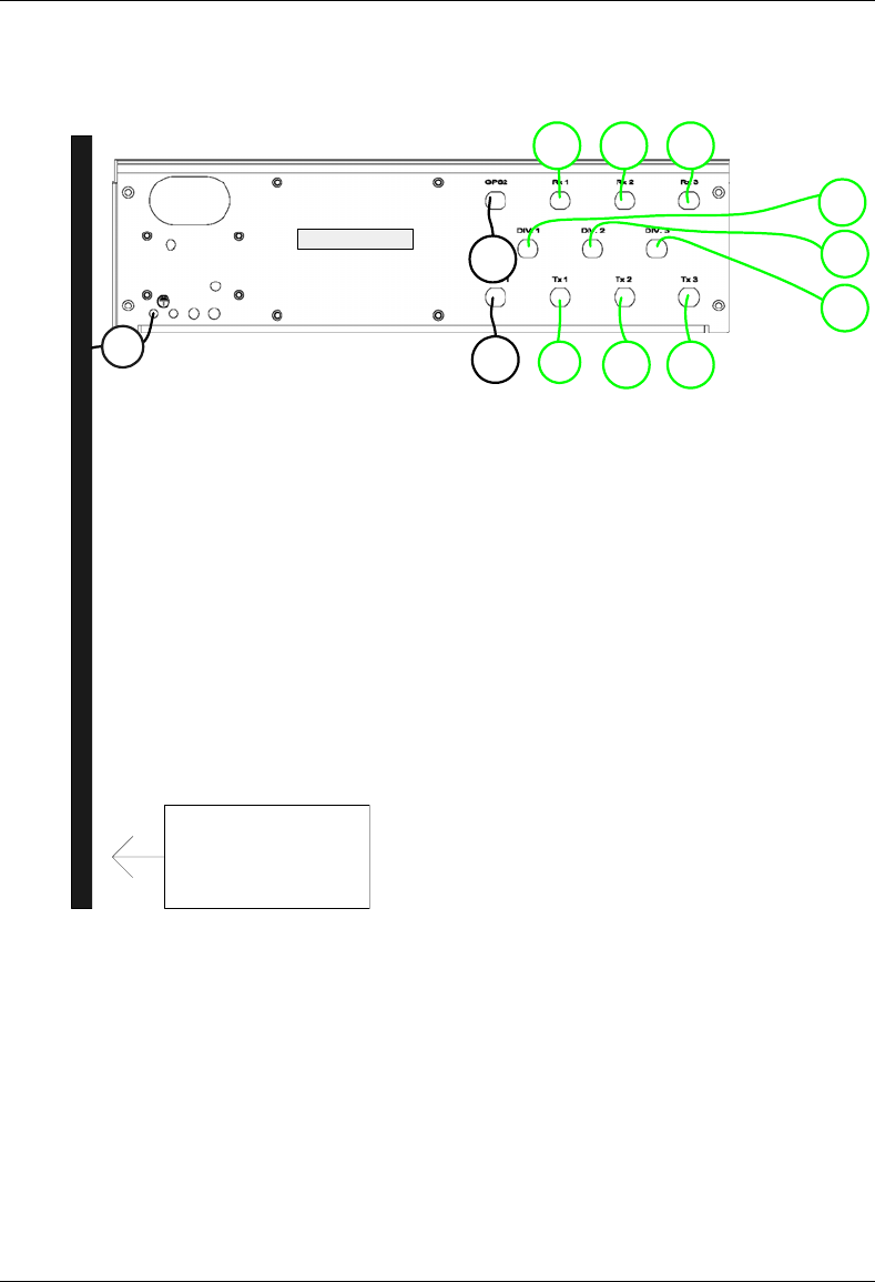
MC-Series System Installation & Testing
Appendix C: Cabling Diagrams: 3-Sector Configuration
RadioFrame Networks, Inc. 131
G_1
RF_9
RF_10
RF_15 RF_21
RF_16 RF_22
GPS_1
DIV_1
DIV_2
DIV_3
GPS_2
GROUND BAR
TOR
MC-Series System Installation & Testing
Appendix C: Cabling Diagrams: 3-Sector Configuration
132 RadioFrame Networks, Inc.
s
s
s
RF_12
RF_7
RF_11
RF_8
T1
T2 T3 T4 T5 T6 T7 T8P_15
P_14
P_1
RF_18
RF_13
RF_17
RF_14
T9
T10
P_17
P_16
G_4
T11 T12 T13 T14 T15 T16
P_2
RF_4
RF_2 RF_5
RF_1
RF_15 RF_16
RF_24
RF_19
RF_23
RF_20
T18
P_19
P_18 T19 T20 T21 T22 T23
P_3 RF_3 RF_6
RF_21 RF_22
G_5
T24
T17
AL_0
AL_1
AL_3
P_2 P_3
RF 1
RF 2
RF 3
P_6 P_7 P_8 P_9 P_10 P_11 P_12
RF_9 RF_10
AL_2
P_4 P_5 P_13
G_2
G_3
PDU
MC-Series System Installation & Testing
Appendix C: Cabling Diagrams: 3-Sector Configuration
RadioFrame Networks, Inc. 133
RBS_1
CSU
ISC 2
ISC1
EAS
BIC
AIC
P_6
P_8
P_9
P_11
P_12
G_8
G_10
G_11
G_12
G_14
P_10
RF_1RF_2RF_3 RF_4RF_5
RF_6
P_22 P_21 P_20
AL_1
AL_2
AL_3 DAT_2 DAT_1
DAT_1
DAT_2
DAT_3
DAT_5
DAT_4
G_9
G_13
DAT_3
C_3C_2
ISC ISC ISC
T T
TT T
ISC ISC
T1
T T
ISC
ISC ISC
ISC
ISC
ISC
C_4 C_5 C_6 C_7 C_8 C_9
C_10
C_11
C_12
AL_0
P_7 GPS1
CLK_1
DAT_6
GPS2
G_6
G_7

MC-Series System Installation & Testing
Appendix D: Cabling Diagrams: Omni Configuration
134 RadioFrame Networks, Inc.
D. Cabling Diagrams: Omni Configuration
Figure 42 MC-Series System Omni Configuration
PDU
reserved for
p
ower
p
lant
RF SHELF
A
IC
BIC
EAS
ISC 1
ISC 2
CSU
RBS
future RBS
future RF SHELF

MC-Series System Installation & Testing
Appendix D: Cabling Diagrams: Omni Configuration
RadioFrame Networks, Inc. 135
The following table is the index to the following three figures that show cabling for the standard
omni MC-Series System.
Power Part Number From To Notes
P_1 820-0616-10 PDU: RF 1 RF Shelf 1 Power
P_2 820-0616-10 PDU: RF 2 RF Shelf 2 Power: connected to PDU only
P_3 820-0616-20 PDU: RF 3 RF Shelf 3 Power: connected to PDU only
P_4 820-0616-30 PDU: RBS 3 RBS 3 Power: connected to PDU only
P_5 820-0616-30 PDU: RBS 2 RBS 2 Power: connected to PDU only
P_6 820-0616-50 PDU: RBS 1 RBS 1 Power
P_7 820-0615-50 PDU: CSU CSU Power
P_8 820-0613-50 PDU: CTRL 1 ISC 1 Power: primary iSC
P_9 820-0613-50 PDU: CTRL 2 ISC 2 Power: secondary iSC
P_10 820-0616-50 PDU: EAS EAS Power
P_11 820-0614-00 PDU: BIC BIC Power
P_12 820-0614-10 PDU: AIC AIC Power
P_13 PDU: AUX Power: left unconnected
P_14 102-0011-04 RF Shelf 1: Fan 1 RF Shelf 1: FAN Power
P_15 102-0011-04 RF Shelf 1: Fan 2 RF Shelf 1: FAN Power
P_16 102-0011-04 RF Shelf 2: Fan 1 RF Shelf 2: FAN Power: if present
P_17 102-0011-04 RF Shelf 2: Fan 2 RF Shelf 2: FAN Power: if present
P_18 102-0011-04 RF Shelf 3: Fan 1 RF Shelf 3: FAN Power: if present
P_19 102-0011-04 RF Shelf 3: Fan 2 RF Shelf 3: FAN Power: if present
P_20 102-0011-04 RBS 1: Fan RBS 1: FAN A Power
P_21 102-0011-04 RBS 1: Fan RBS 1: FAN B Power
P_22 102-0011-04 RBS 1: Fan RBS 1: FAN C Power
Ground Part Number From To Notes
G_1 TBD TOR GND BAR
G_2 820-0609-00 PDU GND BAR
G_3 820-0609-00 RF Shelf 1 GND BAR
G_4 820-0609-00 RF Shelf 2 GND BAR connected only to GND BAR
G_5 820-0609-00 RF Shelf 3 GND BAR connected only to GND BAR
G_6 820-0609-00 RBS 3 GND BAR connected only to GND BAR
G_7 820-0609-00 RBS 2 GND BAR connected only to GND BAR
G_8 820-0609-00 RBS 1 GND BAR
G_9 820-0609-10 CSU GND BAR
G_10 820-0609-10 ISC1 GND BAR
G_11 820-0609-10 ISC2 GND BAR
G_12 820-0609-10 EAS GND BAR
G_13 820-0609-00 BIC GND BAR
G_14 820-0609-00 AIC GND BAR

MC-Series System Installation & Testing
Appendix D: Cabling Diagrams: Omni Configuration
136 RadioFrame Networks, Inc.
RF Part Number From To Notes
GPS_1 820-0620-00 ISC 1: GPS TOR: GPS 1 RF CABLE
GPS_2 820-0620-00 ISC 2: GPS TOR: GPS 2 RF CABLE
RF_1 820-0611-20 RF Shelf 1: Tx IN A RBS 1: Tx A RF CABLE
RF_2 820-0611-20 RF Shelf 1: Tx IN B RBS 1: Tx B RF CABLE
RF_3 820-0611-20 RF Shelf 1: Tx IN C RBS 1: Tx C RF CABLE
RF_4 820-0611-20 RF Shelf 1: Rx OUT A RBS 1: Rx A RF CABLE
RF_5 820-0611-20 RF Shelf 1: Rx OUT B RBS 1: Rx B RF CABLE
RF_6 820-0611-20 RF Shelf 1: Rx OUT C RBS 1: Rx C RF CABLE
RF_7 820-0600-10 RF Shelf 1: TX IN RF Shelf 1: PA OUT RF CABLE
RF_8 820-0600-00 RF Shelf 1: TX TEST PORT RF Shelf 1: Tx TEST RF CABLE
RF_9 820-0610-30 RF Shelf 1: TX OUT TOR: Tx 1 RF CABLE
RF_10 820-0610-30 RF Shelf 1: RX IN TOR: Rx 1 RF CABLE
RF_11 820-0600-10 RF Shelf 1: RX OUT RF Shelf 1: LNA IN RF CABLE
RF_12 820-0600-20 RF Shelf 1: RX OUT DIV RF Shelf 1: LNA DIV IN RF CABLE
RF_15 820-0610-30 RF Shelf 2: TX OUT TOR: Tx 2 If present
RF_16 820-0610-30 RF Shelf 2: RX IN TOR: Rx 2 If present
RF_21 820-0610-30 RF Shelf 3: TX OUT TOR: Tx 3 If present
RF_22 820-0610-30 RF Shelf 3: RX IN TOR: Rx 3 If present
DIV_1 820-0610-30 TOR: DIV 1 RF Shelf 1 connected only to TOR
DIV_2 820-0610-30 TOR: DIV 2 RF Shelf 2 connected only to TOR
DIV_3 820-0610-30 TOR: DIV 3 RF Shelf 3 connected only to TOR
RF Term. Part Number From To Notes
T1 514-0002-00 RF Shelf 1: RX IN DIV RF Termination
T6 514-0002-00 RF Shelf 1: Rx DIV OUT A RF Termination
T7 514-0002-00 RF Shelf 1: Rx DIV OUT B RF Termination
T8 514-0002-00 RF Shelf 1: Rx DIV OUT C RF Termination
Alarm Part Number From To Notes
AL_0 TBD PDU: STATUS EAS: CONTROL
AL_1 820-0607-00 RF Shelf 1: ALARM RBS: ALARM INPUT A Serial
RFN Part Number From To Notes
DAT_1 111-0566-00 RBS 1: 10/100 RFN A AIC: ERTM PORT 1 UTP
DAT_2 111-0566-00 RBS 1: 10/100 RFN B AIC: ERTM PORT 2 UTP
DAT_3 111-0566-00 RBS 1: 10/100 RFN C AIC: ERTM PORT 3 UTP
DAT_4 111-0565-00 BIC: CRTC 10baseT - ISC BIC: ERTM PORT 1 UTP
DAT_5 111-0565-00 BIC: ERTM PORT 2 AIC: ERTM PORT 4 UTP
DAT_6 111-0001-02 BIC: CRTC 10base2 - ISC ISC 1: 10B2-1 COAX
CLK_1 111-0001-02 BIC: ERTM 5MHz/1PPS IN
ISC 1: SITE REF OUT
1 COAX
MC-Series System Installation & Testing
Appendix D: Cabling Diagrams: Omni Configuration
RadioFrame Networks, Inc. 137
G_1
RF_9
RF_10
RF_15 RF_21
RF_16 RF_22
GPS_1
DIV_1
DIV_2
DIV_3
GPS_2
GROUND BAR
TOR
MC-Series System Installation & Testing
Appendix D: Cabling Diagrams: Omni Configuration
138 RadioFrame Networks, Inc.
s
RF_12
RF_7
RF_11
RF_8
T1
T6 T7 T8P_15
P_14
P_1
G_4
RF_4
RF_2 RF_5
RF_1 RF_3 RF_6
G_5
AL_0
AL_1
P_2 P_3
RF 1
P_6 P_7 P_8 P_9 P_10 P_11 P_12
RF_9 RF_10
P_4 P_5 P_13
G_2
G_3
PDU
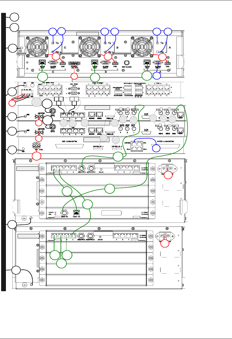
MC-Series System Installation & Testing
Appendix D: Cabling Diagrams: Omni Configuration
RadioFrame Networks, Inc. 139
RBS_1
CSU
ISC 2
ISC1
EAS
BIC
AIC
P_6
P_8
P_9
P_11
P_12
G_8
G_10
G_11
G_12
G_14
P_10
RF_1RF_2RF_3 RF_4RF_5
RF_6
P_22 P_21 P_20
AL_1
DAT_2 DAT_1
DAT_1
DAT_2
DAT_3
DAT_5
DAT_4
G_9
G_13
DAT_3
C_3C_2
ISC ISC ISC
T T
TT T
ISC ISC
T1
T T
ISC
ISC ISC
ISC
ISC
ISC
C_4 C_5 C_6 C_7 C_8 C_9
C_10
C_11
C_12
AL_0
P_7 GPS1
CLK_1
DAT_6
GPS2
G_6
G_7
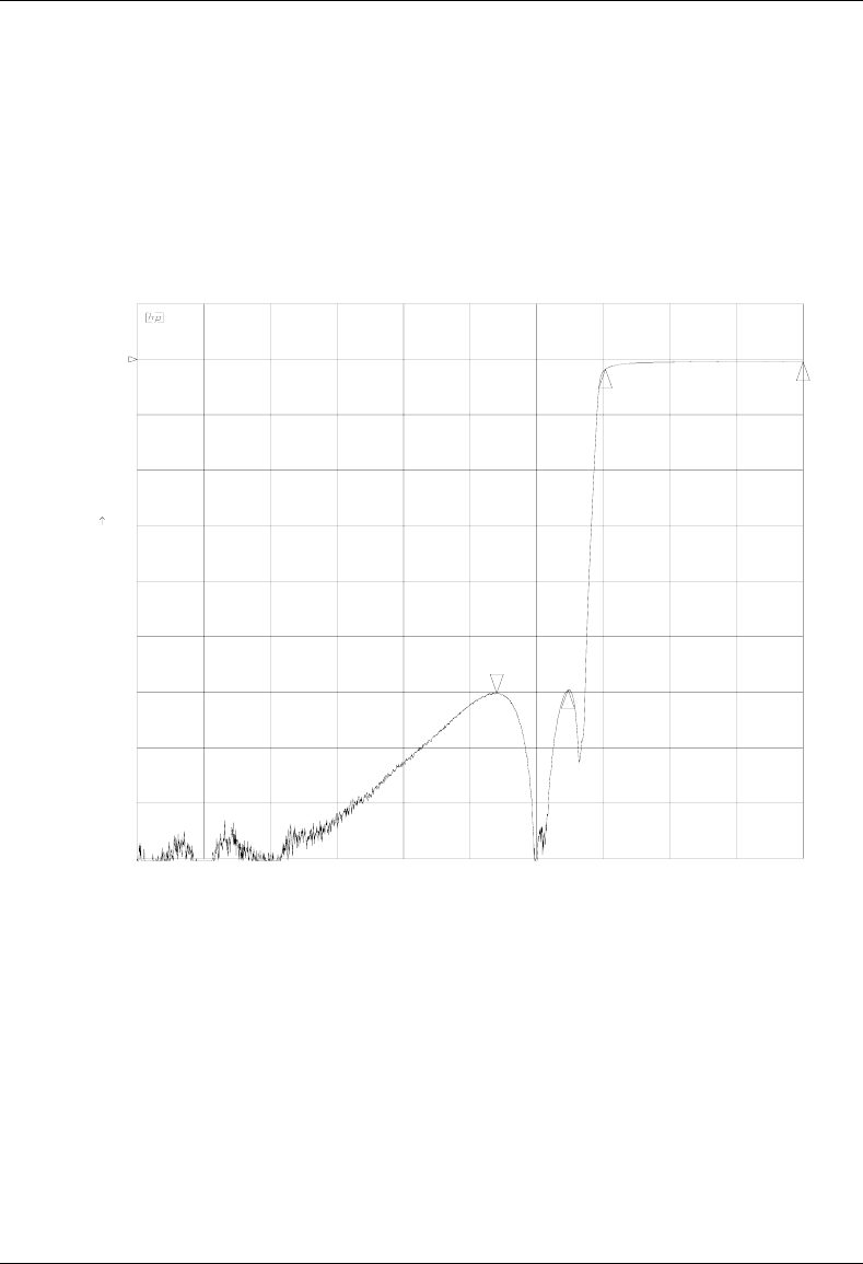
MC-Series System Installation & Testing
Appendix E: Tx / Rx Curves
140 RadioFrame Networks, Inc.
E. Tx / Rx Curves
The TX filter frequency response is shown in the following illustration.
CH1 S 12 log MAG 10 dB/ REF 0 dB
START 806.000 000 MHz STOP 870.000 000 MHz
LARK PN 4C806-812 SN 23639-03
C?
PRm
20 Jul 2004 13:32:09
12
3
4
4_:-60.167 dB
840.566 401 MHz
1_:-1.7807 dB
851 MHz
2_:-.4818 dB
870 MHz
3_:-59.574 dB
847.425 MHz
Figure 43 Transmit filter frequency response
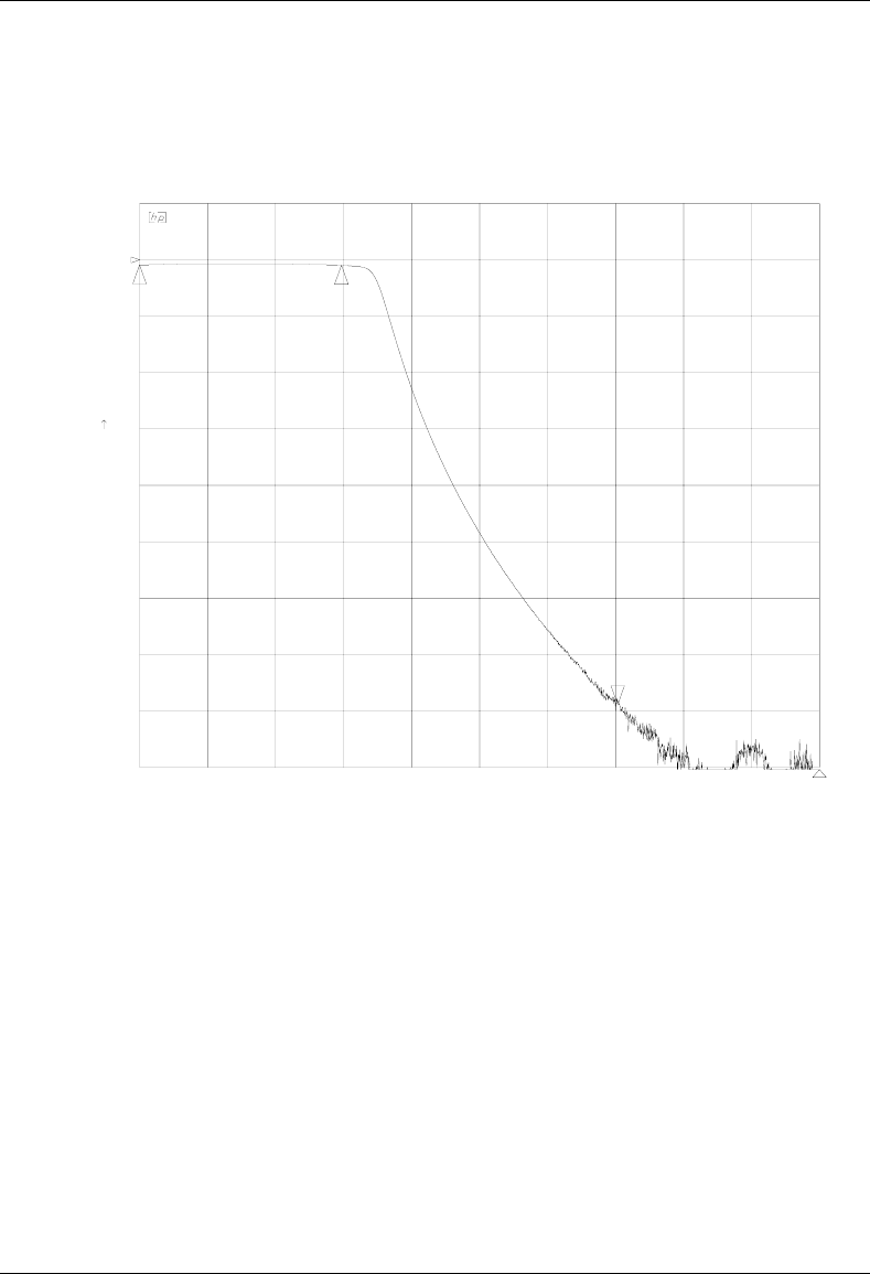
MC-Series System Installation & Testing
Appendix E: Tx / Rx Curves
RadioFrame Networks, Inc. 141
The RX filter response is shown in the following illustration.
CH1 S 12 log MAG 10 dB/ REF 0 dB
START 806.000 000 MHz STOP 870.000 000 MHz
*
LARK PN 4C806-813 SN 23640-01
C?
PRm
20 Jul 2004 15:07:29
12
3
4
3_:-78.862 dB
851.000 000 MHz
1_:-.8822 dB
806 MHz
2_:-.9402 dB
825 MHz
4_:-91.838 dB
870 MHz
Figure 44 Receive filter frequency response
MC-Series System Installation & Testing
Appendix F: Functionality Test Procedures
142 RadioFrame Networks, Inc.
F. Functionality Test Procedures
F.1 Interconnect & Dispatch Setup & Voice Quality
Interconnect and Dispatch voice quality will be assessed by evaluating voice links as described in
Tables 6, 7, and 8. RSSI and SQE measurements will be made via the handset. These tests are
to be performed on a selected sample set of links.
Table 8 Interconnect Call Quality, Setup and Stability
Test # MOP/PSTN Carrier # RSSI
(dbm) SQE
(dbm) Quality
(1-5) Sector Duration
(Min)
1 2
2 2
3 2
4 2
5 2
PSTN/MT
1 2
2 2
3 2
4 2
5 2
MO/MT
1 2
2 2
3 2
4 2
5 2
Table 9 Group Dispatch Call Quality, Setup, and Stability
Test # MO/MT Carrier # RSSI
(dbm) SQE
(dbm) Quality
(1-5) Sector Duration
(Min)
1 2
2 2
3 2

MC-Series System Installation & Testing
Appendix F: Functionality Test Procedures
RadioFrame Networks, Inc. 143
Test # MO/MT Carrier # RSSI
(dbm) SQE
(dbm) Quality
(1-5) Sector Duration
(Min)
4 2
5 2
6 2
7 2
8 2
9 2
10 2
Table 10 Private Dispatch Call Quality, Setup, and Stability
Test # MO/MT Carrier # RSSI
(dbm) SQE
(dbm) Quality
(1-5) Sector Duration
(Min)
1 2:30
2 2:30
3 2:30
4 2:30
5 2:30
6 2:30
7 2:30
8 2:30
9 2:30
10 2:30
F.2 Packet Data Service Connection and Latency
The Packet Data service will be tested and verified on the MC-Series System. Motorola's Packet
Data Applet (laptop) will be used to connect to Nextel's Packet Data network over the MC-Series
System, using a tethered connection with a Motorola handset.
Several samples of PING requests will be sent to a Router in Nextel's Packet Data network and
average round trip times will be recorded to measure latency. The table below presents the data
to be collected for each ping using the MC-Series System. These tests shall be performed using
Windows 2000 OS and the timeout for each ping reply shall be set to 2000 milliseconds.
MC-Series System Installation & Testing
Appendix F: Functionality Test Procedures
144 RadioFrame Networks, Inc.
Table 11 Packet Data Latency over the MC-Series System (Ping –n 100 –w 2000 xx.xxx.xxx.x )
Test
# Handset Carrier
# RSSI
(dbm) SQE
(dbm) Ping
(No. Echos) Router
(IP Address) Avg. Round
Trip Time
(msec)
Packet
Loss
(%)
1 100 xxx.xxx.xxx.x
2 100 xxx.xxx.xxx.x
3 100 xxx.xxx.xxx.x
4 100 xxx.xxx.xxx.x
5 100 xxx.xxx.xxx.x
The following table presents (baseline) data collected for each ping using a Motorola Macrocell in
order to average Round Trip time over the MC-Series System versus over Motorola standard
Base Station equipment.
Table 12 Packet Data Latency over Motorola EBTS
Test
# Handset Carrier
# RSSI
(dbm) SQE
(dbm) Ping
(No. Echos) Router
(IP Address) Average
Round Trip
Time (msec)
Packet
Loss
(%)
1 100 xxx.xxx.xxx.x 0
2 100 xxx.xxx.xxx.x 0
3 100 xxx.xxx.xxx.x 0
4 100 xxx.xxx.xxx.x 0
5 100 xxx.xxx.xxx.x 0
F.3 Short Message Service
The Short Message Service (SMS) will be tested and verified by initiating the delivery of a voice
mail notification to the handset via one of the iDEN RadioBlade links.
1 Navigate on a network connection to the Internet.
2 Enter http://www.nextel.com/ in the web browser.
3 On the Nextel home page, enter the 10-digit phone number of the test phone in the
messaging field, which will display the mobile messaging page.
4 Enter a short text message into the field for message, and also enter a subject in the subject
line.
5 Press the Send button.
The message should appear on the test phone within a few minutes.
MC-Series System Installation & Testing
Appendix F: Functionality Test Procedures
RadioFrame Networks, Inc. 145
F.4 Handover and Cell Reselection
Handover and Cell Reselection shall be tested and verified that mobiles on the MC-Series
System successfully handoff to the macro-cellular network during an interconnect call. These
tests shall also verify that mobiles on the MC-Series System perform successful cell reselection
when in an idle state. The following table presents the data to be collected for the handover and
reselection tests.
Table 13 Handover & Idle Mode Reselection
Test # Handover (Mobile #) Carrier # from (HEX) Carrier # to (HEX)
1
2
3
Cell Reselection (Mobile #)
1
2
3
F.5 Interconnect Connection Stability and SQE Performance
A single link for 3:1 Interconnect will be maintained for 30 minutes each. The following table
presents the data to be collected for each selected link. The iDEN Field Test Application (IFTA)
shall be used in “Single Cell” mode to observe the SQE performance and plotted over time.
Table 14 Interconnect Connection Stability
Interconnect #1 Carrier # RSSI (dBm) SQE (dB) Sector Duration (min)
30
Interconnect #2
30
Interconnect #3
F.6 Dispatch Connection Stability
To verify Dispatch connection stability, a Dispatch (private or group) call will be maintained for
several minutes. The following table presents the data to be collected for each dispatch call.
Table 15 Dispatch Connection Stability
Dispatch #1 Carrier # RSSI (dB) SQE (dB) Sector Quality (1-5) Duration (min)
3

MC-Series System Installation & Testing
Appendix F: Functionality Test Procedures
146 RadioFrame Networks, Inc.
Dispatch #2
4
Dispatch #3
5
F.7 Idle SQE Testing and Validation
Using the iFTA tool in “Single Cell” mode, record the idle RSSI and SQE values for the control
channel for at least one hour per sector, while the mobile remains fixed.
Then, conduct the same procedure while walking the facility for approximately 15 minutes.
F.8 System Self-Recovery Test
The following test is to determine the ability of the MC-Series System to recover from various
iSC-3 conditions.
1 Loss of T1
While the MC-Series System is operating, disconnect the T1 connection to the iSC-3 for one
minute, and then reconnect it. Monitor the system recovery, and then validate the system by
placing a successful call on each sector.
2 iSC-3 Power Loss
While the MC-Series System is operating, the iSC-3 shall be power cycled and system
recovery will be monitored and validated by placing a successful call on each sector.
3 Loss of GPS
While the MC-Series System is operating, the GPS connection to the iSC-3 will be
disconnected until all Satellites are lost and then reconnected. System recovery will be
monitored and validated by placing a successful call on each sector.
4 New datafill download
System recovery will be verified by pushing a new datafill download to the iSC-3.
F.9 Packet Data Stability and Throughput
The Packet Data stability and throughput to the Internet will be verified. A tethered Packet Data
connection will be set up on a laptop and speed tested by using the www.bandwidthplace.com
website. This continuous download of data stream will validate system stability and help to
quantify user experience of Packet Data over the MC-Series System.
F.10 Validation of 'Unable to Key BR' Alarm
While the MC-Series System is operating, disconnect any system component, from the BIC to the
RBS, and monitor the OMC to verify that MC-Series System generates the ‘Unable to Key BR’
alarm.
The MC-Series System provides fault alarming and isolation within System Manager for individual
components, which consists of detecting catastrophic faults that prevent an MC-Series System
component from responding to a periodic “ping”. All fault alarms generated by the MC-Series

MC-Series System Installation & Testing
Appendix F: Functionality Test Procedures
RadioFrame Networks, Inc. 147
System are received at the OMC via the iSC. The ‘Unable to Key BR’ alarm will appear at the
OMC as minor, major, or critical as follows (for more information about alarms, refer to section 8.5
Alarm Resolution Procedures):
'Unable to Key BR' alarm severity Indication
minor An iDEN RadioBlade has failed.
major An RF Shelf has failed.
critical A card in a chassis unit has failed (except for the BIC CRIC,
which is responsible for returning the alarm information.)
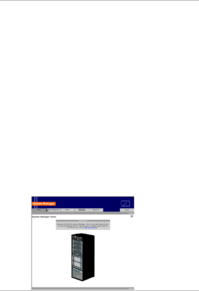
MC-Series System Installation & Testing
Appendix G: System Manager
148 RadioFrame Networks, Inc.
G. System Manager
System Manager is the MC-Series System web-based interface. System Manager provides
status, performance, and alarm information for the MC-Series System and its components, as
well as diagnostic tools and online help. When new releases of System Manager are provided,
download the new release as described in section 8.1 Upgrading System Software.
If any of the following information is changed in System Manager, also note those changes on the
Equipment Inventory or site as-built documentation:
Figure 45 Physical location
Figure 46 IP addresses
Figure 47 Port connections
Figure 48 Sector locations
G.1 Logging In to System Manager
1 Connect a laptop computer to port 8 of the BIC CRIC using an Ethernet (CAT5) cable.
2 Start System Manager by setting the IP address of the laptop to the same subnet that was
setup in the system (default 192.168.200.5).
The System Manager Home page appears which contains five tabs to select from to set up
and monitor the RadioFrame System MC-Series:
• Home—displays a welcome banner and a link for setting up users and changing the MC-
Series System password.
• System Configuration—depicts the status of the BIC, AIC, RBS, and RadioBlades.
• Alarms—displays alarm information.
• Performance Monitoring—displays real-time performance information.
• Diagnostics—provides tools for testing.
• Support—displays support information, including online help.
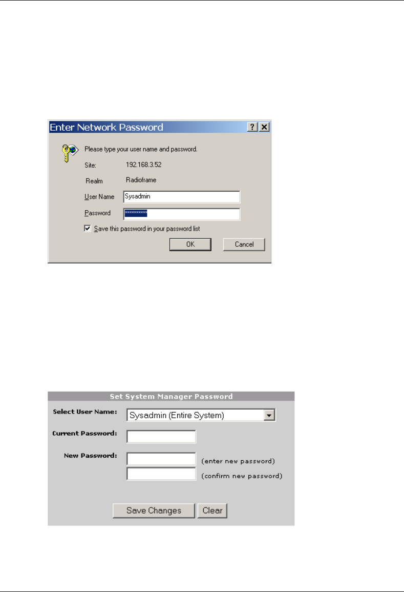
MC-Series System Installation & Testing
Appendix G: System Manager
RadioFrame Networks, Inc. 149
3 To log in, select any tab.
4 For User Name, type the MC-Series System user name.
5 For Password, type the MC-Series System password.
To save the password, check ‘Save this password in your password list’ checkbox.
6 Select OK.
G.1 Changing the System Password
1 Select the Home tab, and then select the User Provisioning link.
2 For Select User Name, choose the appropriate system title from the dropdown menu.
Typically, choose Sysadmin (Entire System) unless instructed to do otherwise.
3 Type the Current Password.
4 Type the New Password and confirm it, then select Save Changes.
MC-Series System Installation & Testing
Appendix G: System Manager
150 RadioFrame Networks, Inc.
G.2 Navigating the System Configuration
The System Configuration page displays icons depicting the AIC, BIC and the RBS (see the
following illustration). The colored bar beneath each icon represents the status of that component:
Color Status Indicator Description
Green Active The component is installed, configured, and operational.
Yellow Inactive The component is installed, but has not been configured.
Red Alarm The component has returned an alarm condition. Refer to section
7 “Schedule and Unscheduled Maintenance” for specific alarm
conditions.
1 To view configuration information for a component, select its icon.
The component configuration page displays the device name, IP address, building address,
and other pertinent information.
2 To return to a previous page, select the component pathname at the top of the tab (System
Configuration>BIC>AIC…), or to return to the BIC configuration page, select the System
Configuration tab at any time.
MC-Series System Installation & Testing
Appendix G: System Manager
RadioFrame Networks, Inc. 151
G.3 Viewing the Status of the RadioBlades
Select the RBS STATUS link at the bottom of the System Configuration page. The RBS Status
page displays an icon for each RadioBlade installed in the RBS, and indicates the status of the
RadioBlade and whether or not it is locked. At the top of the page are three icons representing
the status of each group (A, B, and C) in the RBS.
MC-Series System Installation & Testing
Appendix G: System Manager
152 RadioFrame Networks, Inc.
G.4 Locking and Unlocking a RadioBlade
Select the RadioBlade icon or the RadioBlade Statistics link at the top of the RBS Status page.
The RadioBlade Statistics page displays the following information for each iDEN RadioBlade:
Figure 49 RB Slot (1-24)
Figure 50 MAC Address
Figure 51 State
Figure 52 Carrier ID
Figure 53 BR ID
Figure 54 Cabinet
Figure 55 Position
Figure 56 Locked/Unlocked
To lock or unlock a RadioBlade, select the icon in the Locked/Unlocked column.
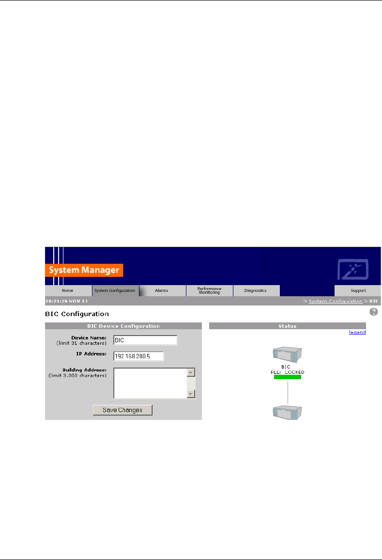
MC-Series System Installation & Testing
Appendix G: System Manager
RadioFrame Networks, Inc. 153
G.5 Changing the Device Name, IP Address, or Building Location
The System Configuration page displays the configuration for the selected component (BIC, AIC,
and RBS) including the Device Name, IP Address, and Building Address—this information can be
changed at any time. For the BIC, this page also displays External IP Configuration, the
information that systems outside the MC-Series System use to recognize it, including the Default
Gateway (the IP address of the CSU).
1 Select the icon of the component to be change.
2 For Device Name, enter up to 31 alphanumeric characters to uniquely identify the
component.
3 The IP Address is assigned during the installation of the MC-Series System, and doesn’t
need to be changed.
4 For Building Address, enter up to 3,000 alphanumeric characters specifying the location of
the component.
Enter information such as the street address, mailing address, building, and other site
information, as well as the building floor, Telco closet, and cabinet location.
5 Select Save Changes.
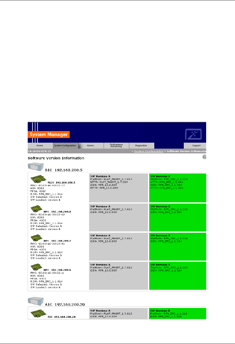
MC-Series System Installation & Testing
Appendix G: System Manager
154 RadioFrame Networks, Inc.
G.6 Viewing Hardware and Software Versions
Select the Software Version Information link on the System Configuration page. The Software
Version Information page depicts each component in the MC-Series System, and each board
installed in each component. For each board the page lists:
Figure 57 MAC—the MAC address
Figure 58 HW—hardware version
Figure 59 FPGA—Field Programmable Gate Array version (manufacturer defined)
Figure 60 ROM—software loaded at time of shipment
Figure 61 SW Selected—currently selected software version, A or B
Figure 62 SW Loaded—currently loaded software version, A or B
Figure 63 SW Versions A—Software version loaded in partition A
Figure 64 SW Versions B—Software version loaded in partition B
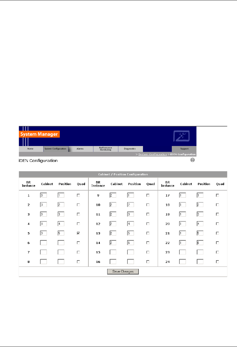
MC-Series System Installation & Testing
Appendix G: System Manager
RadioFrame Networks, Inc. 155
G.7 Changing the iDEN Configuration
The MC-Series System operates as a series of base radios. Each RadioBlade in the MC-Series is
assigned a BR ID and sector (1, 2, or 3). And, each BR in the MC-Series System is assigned a
default cabinet position in the site datafill.
To change the default cabinet position:
1 Select the iDEN Configuration link at the bottom of the System Configuration tab.
2 Enter the Cabinet and Position for the specified BR(s).
3 Select any Quad BRs (only one per group), according to site datafill parameters.
In the following illustration, one quad BR has been selected: BR Instance 5 (cabinet/position
3/5) in the first group. In this example, BRs 5 through 8 make up the quad BR.
4 Select the Save Changes button to save the changes.
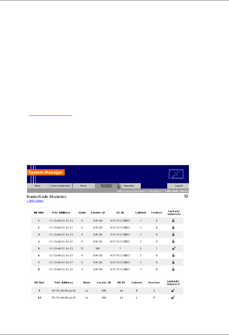
MC-Series System Installation & Testing
Appendix H: BER Test Procedure
156 RadioFrame Networks, Inc.
H. BER Test Procedure
A Bit Error Rate (BER) diagnostic tool has been developed to report Receive (Rx) BER
measurements from the MC-Series System via System Manager. A Motorola R2660
Communications Analyzer can be used as the source of the test signal for the MC-Series System
during the BER test. This section describes the MC-Series System Rx BER diagnostic tool.
H.1 Equipment Connection/Setup
Set up the equipment to measure Rx BER as follows:
1 Connect a laptop to port 8 of the BIC CRIC using an Ethernet (CAT5) cable.
2 Start System Manager and log in.
Launch a browser session and then enter the MC-Series System IP address
(http://169.254.200.5). Select the System Configuration tab to display the login window. For
User Name, type Sysadmin (case sensitive), and for Password type Radioframe (case
sensitive), and then select OK.
3 Display the RadioBlade Statistics page and record which RadioBlades are locked.
On the System Configuration page, select either the RBS icon or the RBS STATUS link to
display the RBS Status page. Then select the RadioBlade Statistics link at the top of the RBS
Configuration page. RadioBlades are listed by slot (1 through 24). If an RB is locked, the icon
in the Locked/Unlocked column is closed. If the RB is unlocked, the lock is open.
4 Lock any unlocked RadioBlades so that none of them are transmitting.
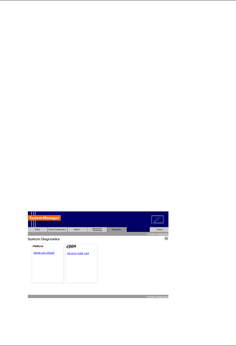
MC-Series System Installation & Testing
Appendix H: BER Test Procedure
RadioFrame Networks, Inc. 157
To lock a RadioBlade, select its open lock icon, and when prompted, select Accept to lock
the RadioBlade.
5 Select the Performance Monitoring tab, and verify that all BRs show the Activity State LDI.
6 On the R2660, set the 10MHz STD toggle switch to INT and power it up.
7 Connect the TOR Rx port that is being tested to the RF IN/OUT or GEN OUT port on the
R2660, depending on the desired test signal level.
8 Set the R2660 to generate an in-bound 1x6 test signal at the desired frequency and signal
level into the Rx port that corresponds to the RadioBlade or group of RadioBlades to be
tested.
Start at –120 dBm, and then increase in 2 dB increments until the BER drops below 2%. The
receive sensitivity value should be less than –106 dBm at 2% BER.
Then, start at –48 dBm and increase in 2 dB increments until the BER goes above 2%. The
maximum input power should be greater than –36 dBm at 2% BER.
If either of these values is not attained, the RadioBlade has failed specifications and should
be replaced.
H.2 BER Test Procedure
This procedure provides commands and responses to measure receiver BER.
1 Display the RadioBlade Statistics page, and unlock the RadioBlade that is to be tested.
Select the RBS icon on the System Configuration page, and then select the RadioBlade
Statistics link at the top of the RBS Status page. Determine which RadioBlade is to be tested,
and then unlock it by selecting its lock icon so that it is opened (unlocked). Refresh the page
every 30 seconds until the State of the RadioBlade has changed to ‘11’, approximately 3
minutes.
2 Select the Diagnostics tab, and then select Bit Error Rate Test.
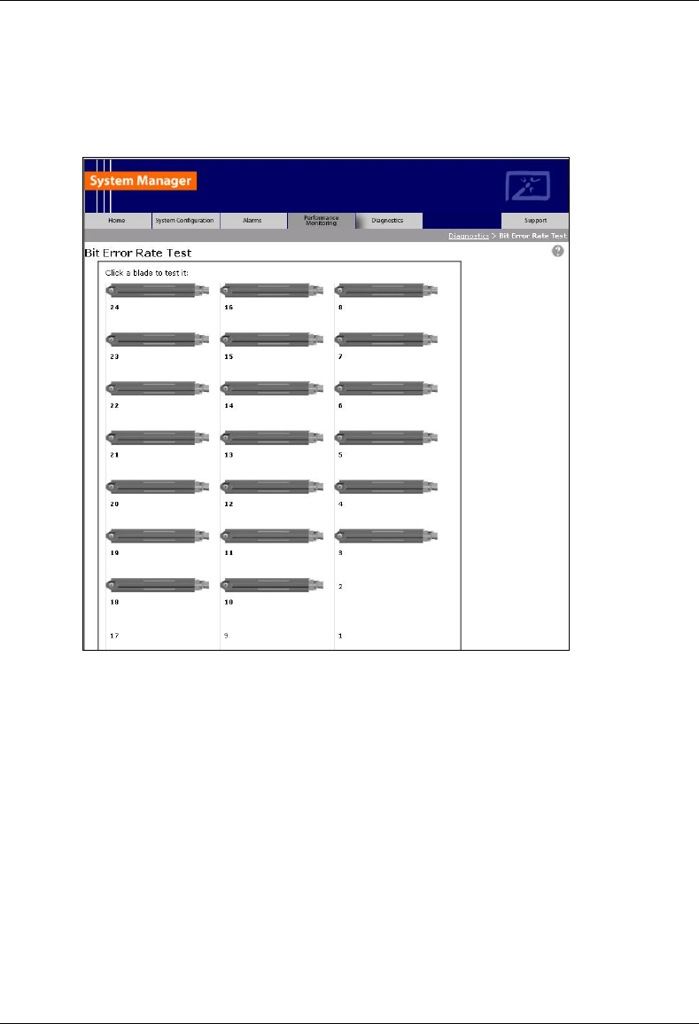
MC-Series System Installation & Testing
Appendix H: BER Test Procedure
158 RadioFrame Networks, Inc.
3 On the Bit Error Rate Test page, select the RadioBlade that is to be tested.
The RadioBlade that is to be tested will show a green status bar—all other RadioBlade status
icons will be yellow. The green RadioBlade is the one that was unlocked in Step 1.
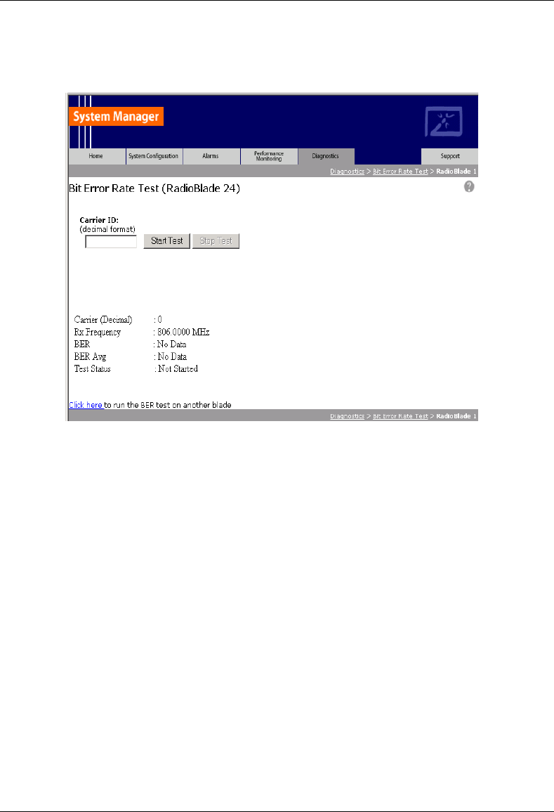
MC-Series System Installation & Testing
Appendix H: BER Test Procedure
RadioFrame Networks, Inc. 159
4 For Carrier ID, enter the carrier ID (in decimal format) to which the R2660 is set, and then
select the Start Test button.
5 Verify that the displayed Rx Frequency matches the desired receive frequency.
6 Approximately every second, the page reports the current BER measurement (BER) and the
running average of the ten latest BER measurements (BER Avg). Record these results, and
then select the Stop Test button.
NOTE: If the warning “Test Signal Timing Out of Lock” appears, cycle power to the R2660
and set it up again to generate an in-bound 1x6 test signal at the desired frequency and
signal level into the Rx port. It may take a few minutes for the R2660 test signal to stabilize.
NOTE: If the only BER measurements reported are 50%, NO DATA, or both, verify that all
procedure steps have been completed. If no problems are found, cycle power to the R2660
and set it up again to generate an in-bound 1x6 test signal at the desired frequency and
signal level into the Rx port. It may take a few minutes for the R2660 test signal to stabilize. If
there's still no change after cycling power to the R2660, select the Stop Test button.
7 When the BER test is complete, lock the RadioBlade that was under test.
Display the RadioBlade Statistics page, and lock the RadioBlade by selecting its lock icon so
that it is closed (locked). Refresh the page every 30 seconds until the State of the
RadioBlade has changed to ‘2’, approximately 3 minutes.
8 Repeat Steps 1 through 7 for each RadioBlade to be tested on this Rx port.

MC-Series System Installation & Testing
Appendix H: BER Test Procedure
160 RadioFrame Networks, Inc.
H.3 Equipment Disconnection
Disconnect equipment after completing the BER testing.
1 Disconnect the R2660 from the Rx port under test.
2 Display the RBS Status page, and verify that all RadioBlade status icons are green.
3 Disconnect the network cable from port 8 of the BIC CRIC.

MC-Series System Installation & Testing
Appendix H: BER Test Procedure
RadioFrame Networks, Inc. 161