RadioFrame Networks MCSERIES10 MC-15 User Manual MC Series Installation Guide
RadioFrame Networks, Inc MC-15 MC Series Installation Guide
UserManual.wiki
>
RadioFrame Networks
>
MCSERIES10 User Manual
Users Manual
Navigation menu
Upload a User Manual
Namespaces
Wiki Guide
HTML
PDF
Info
Views
User Manual
Discussion / Help
Navigation

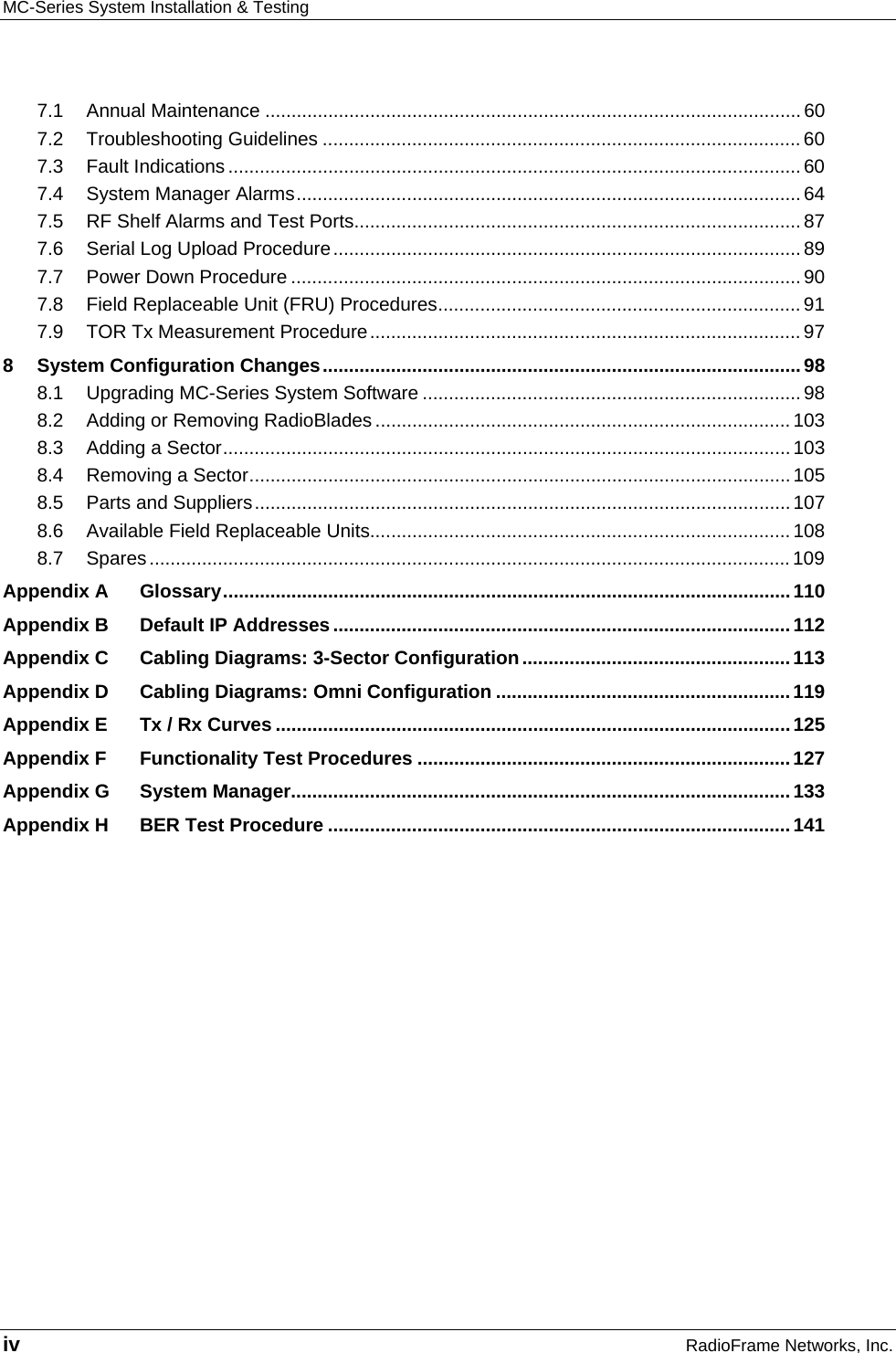
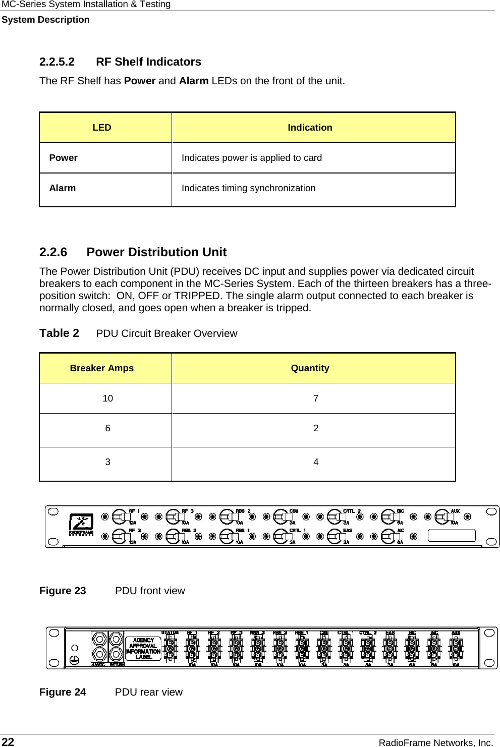
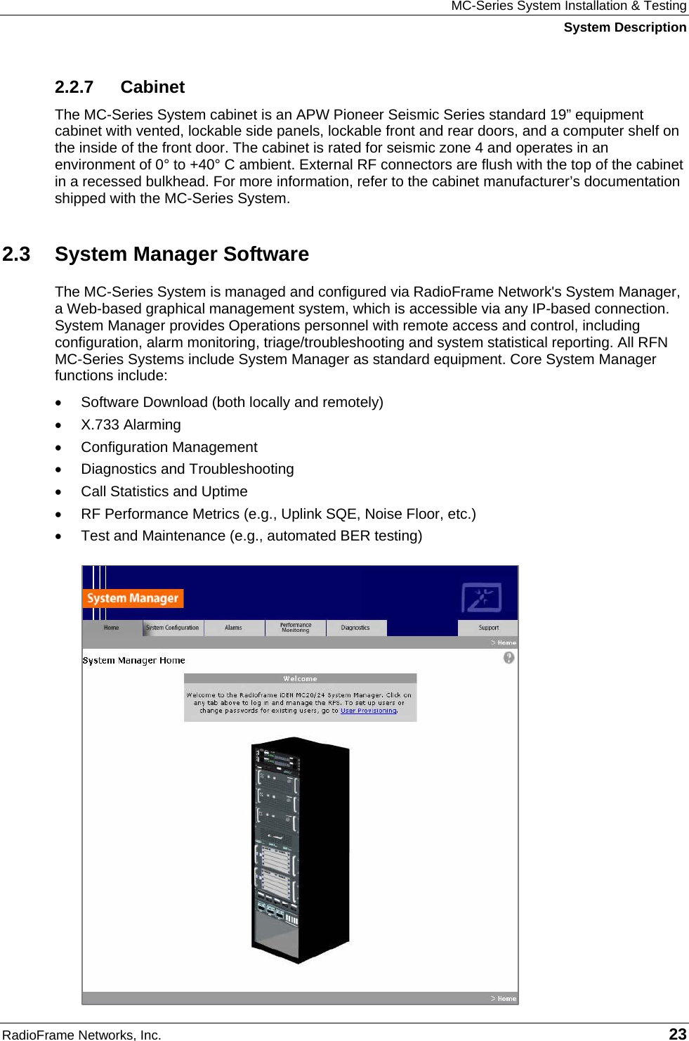
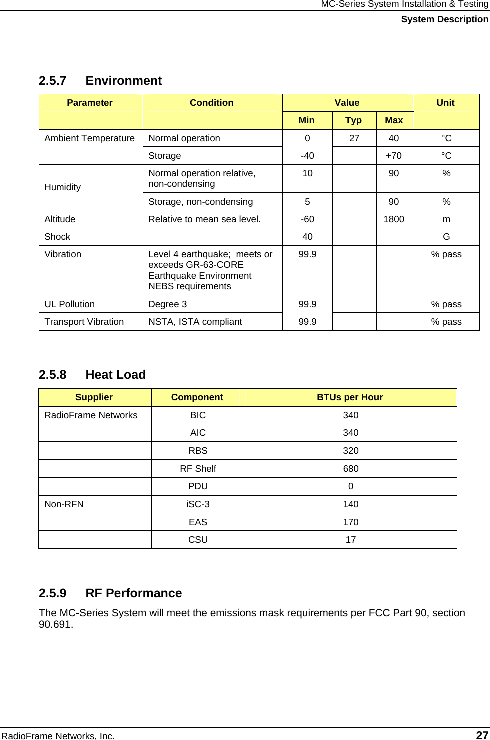
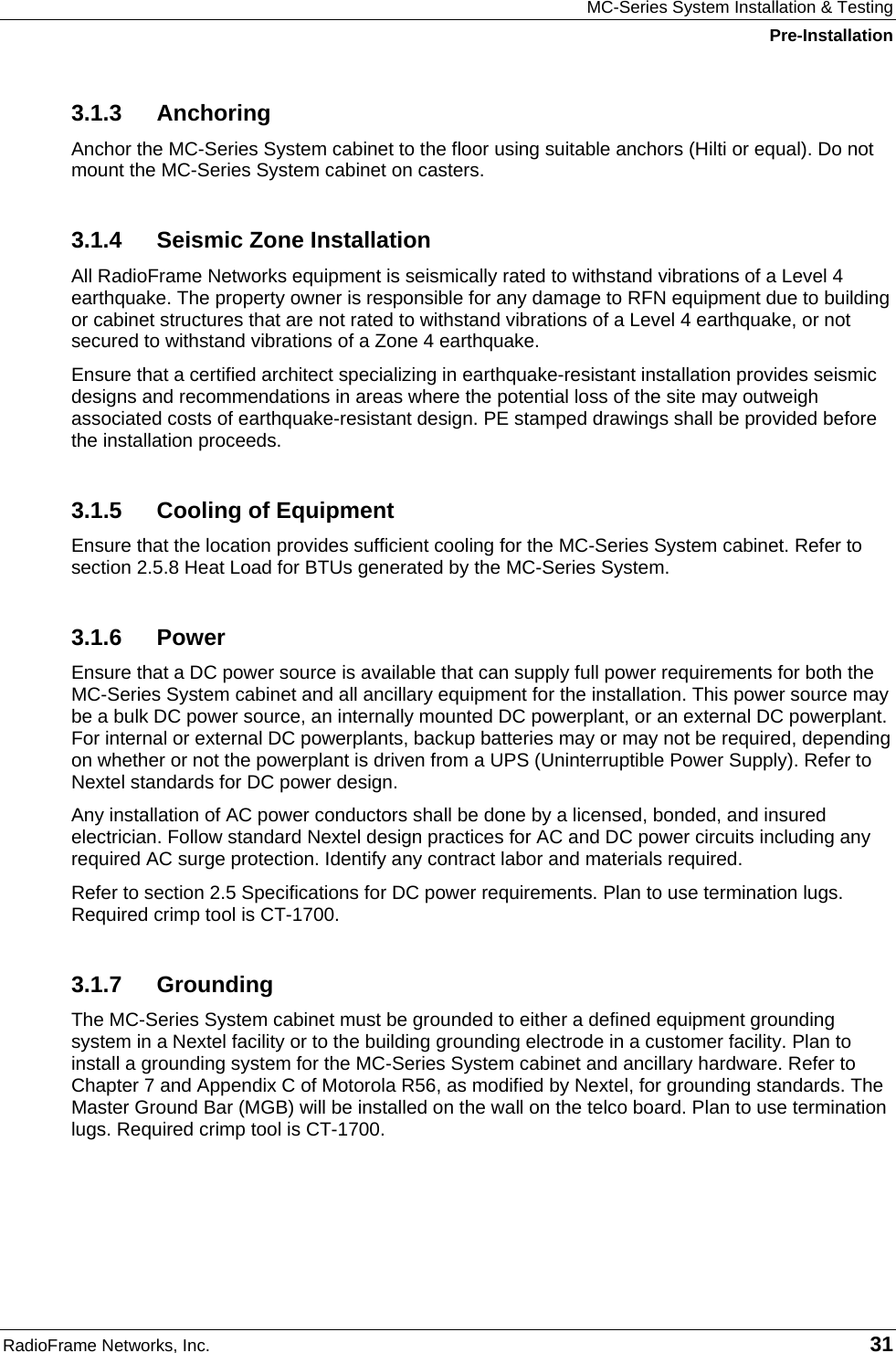
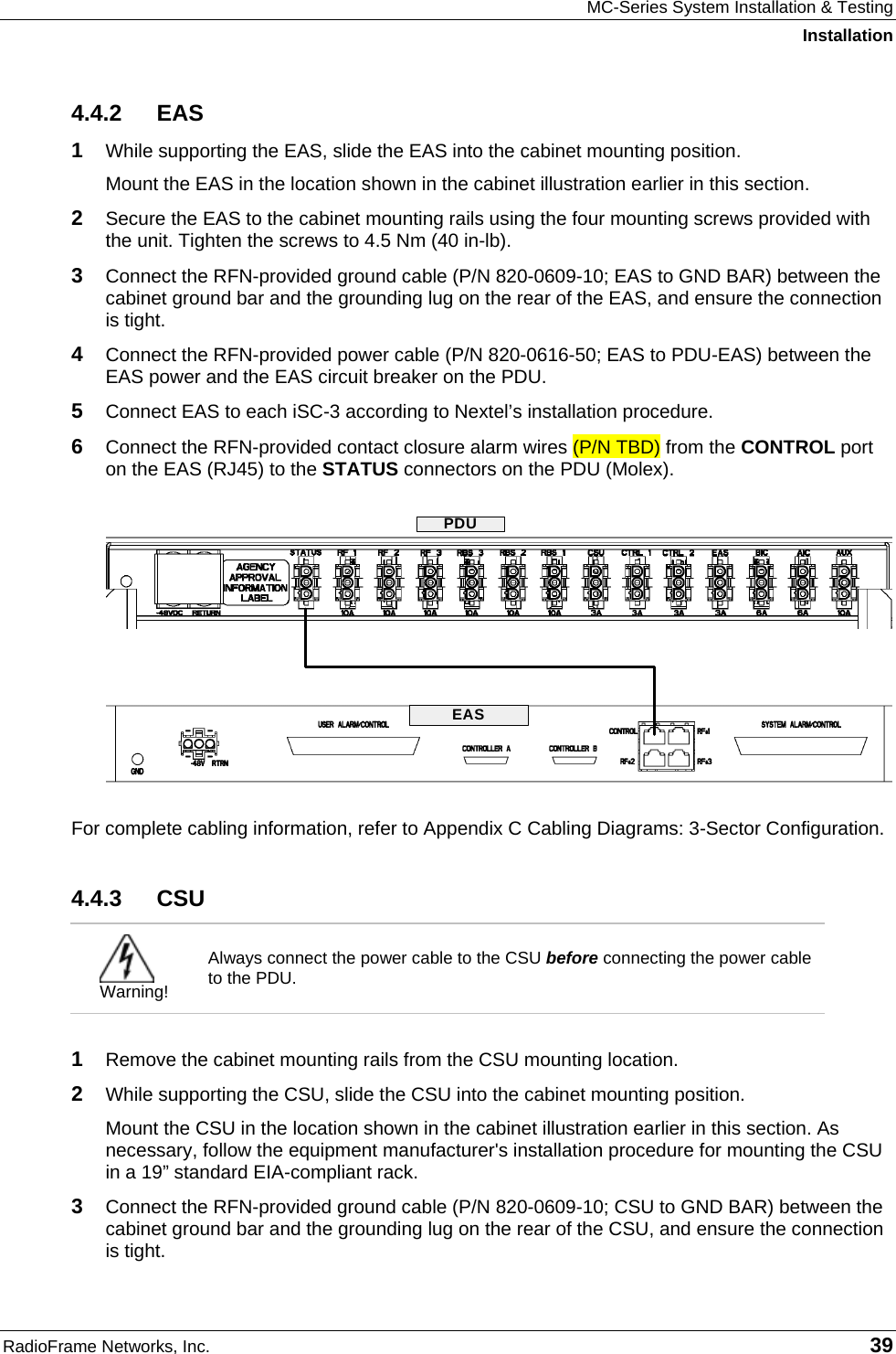
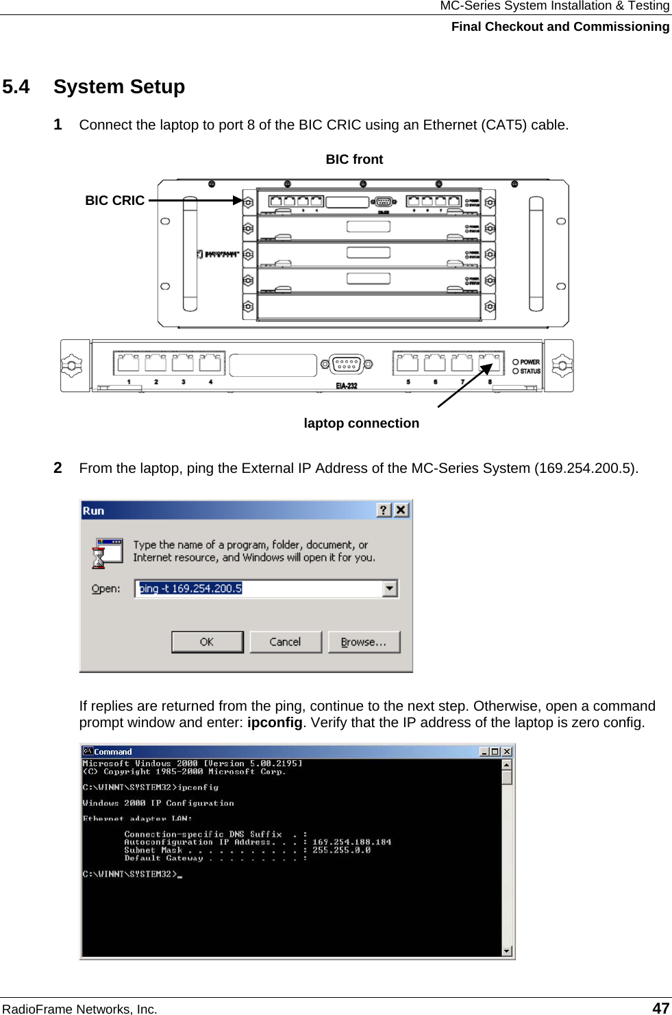
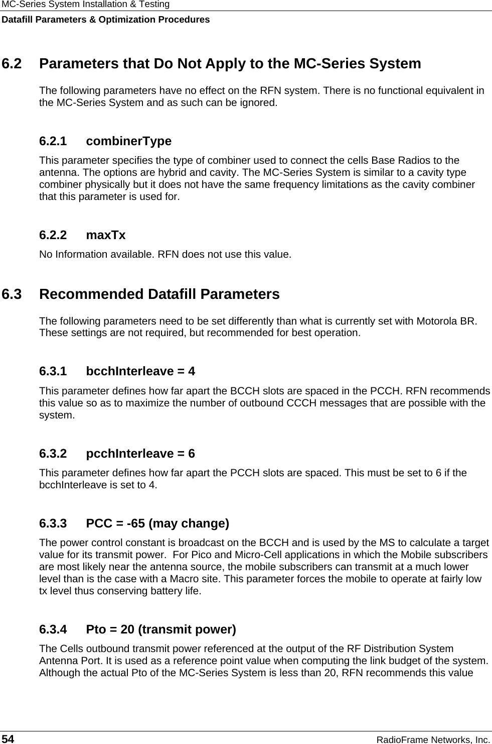
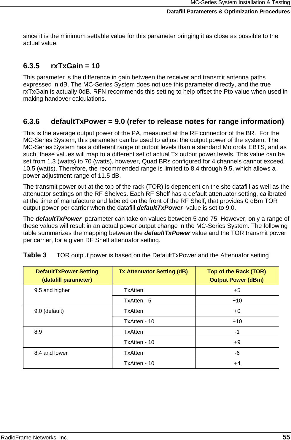
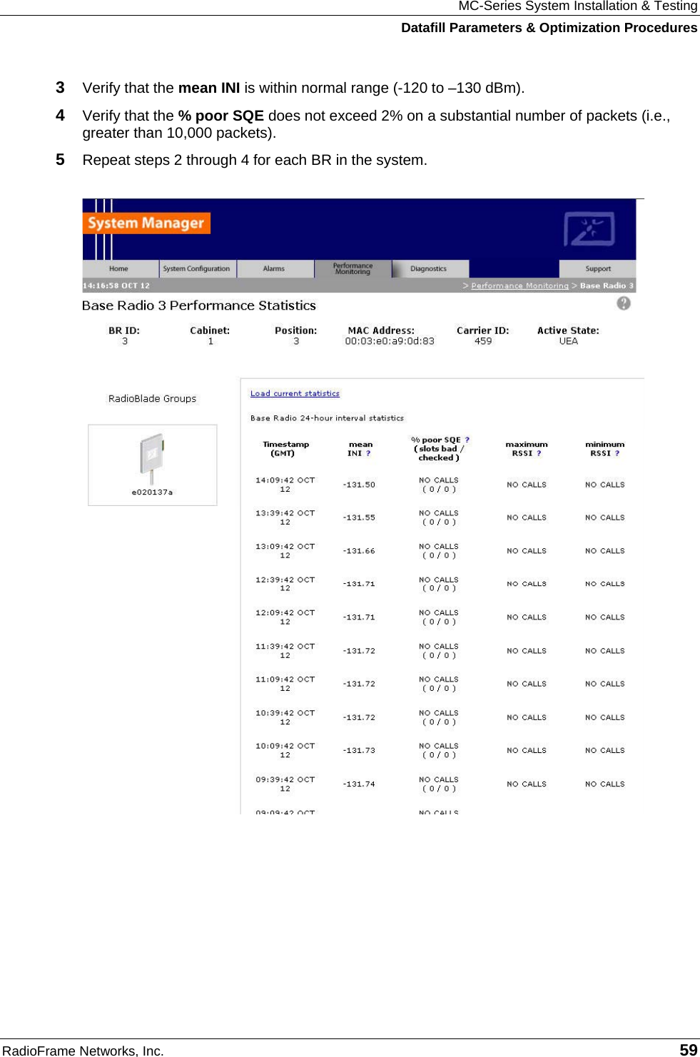
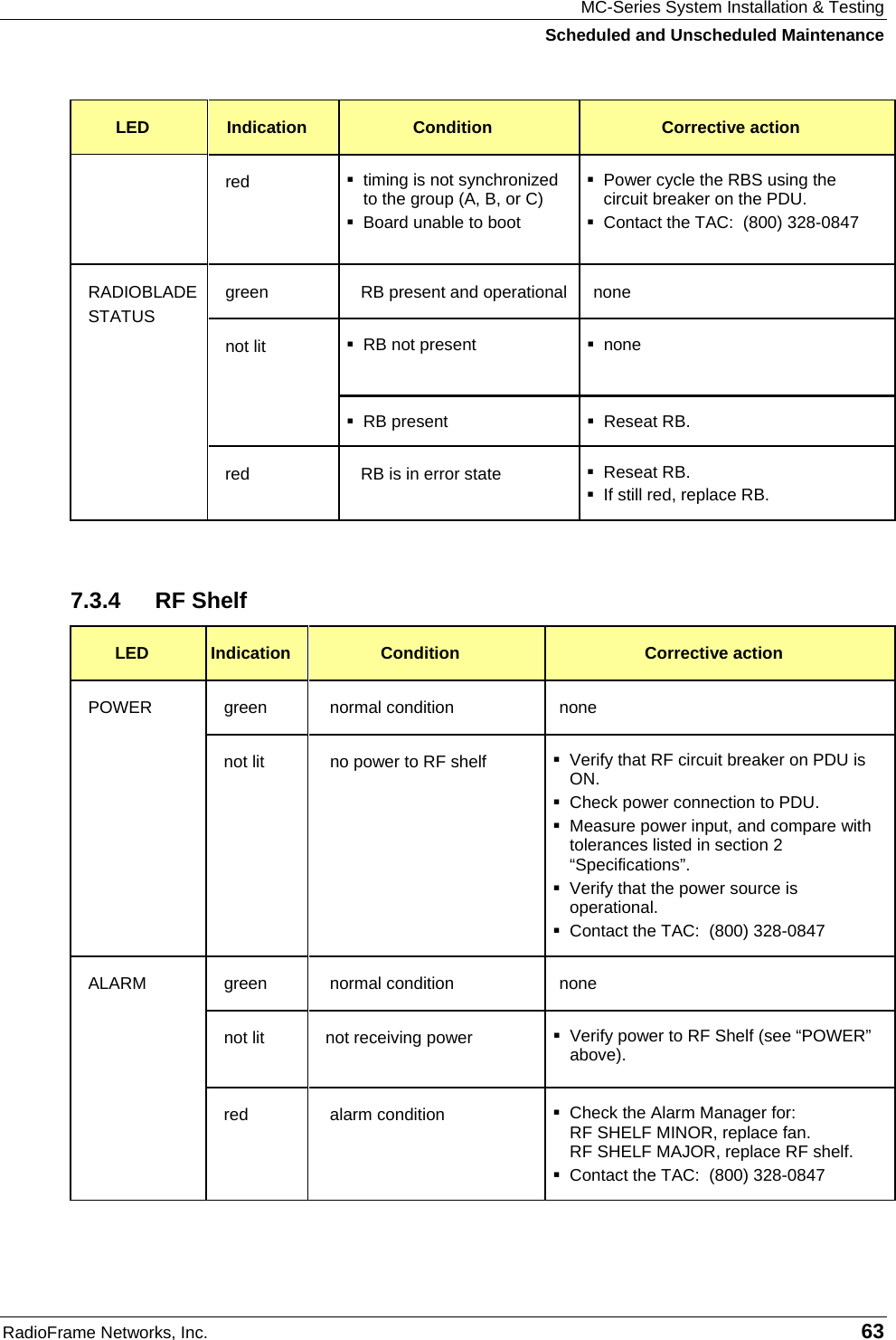
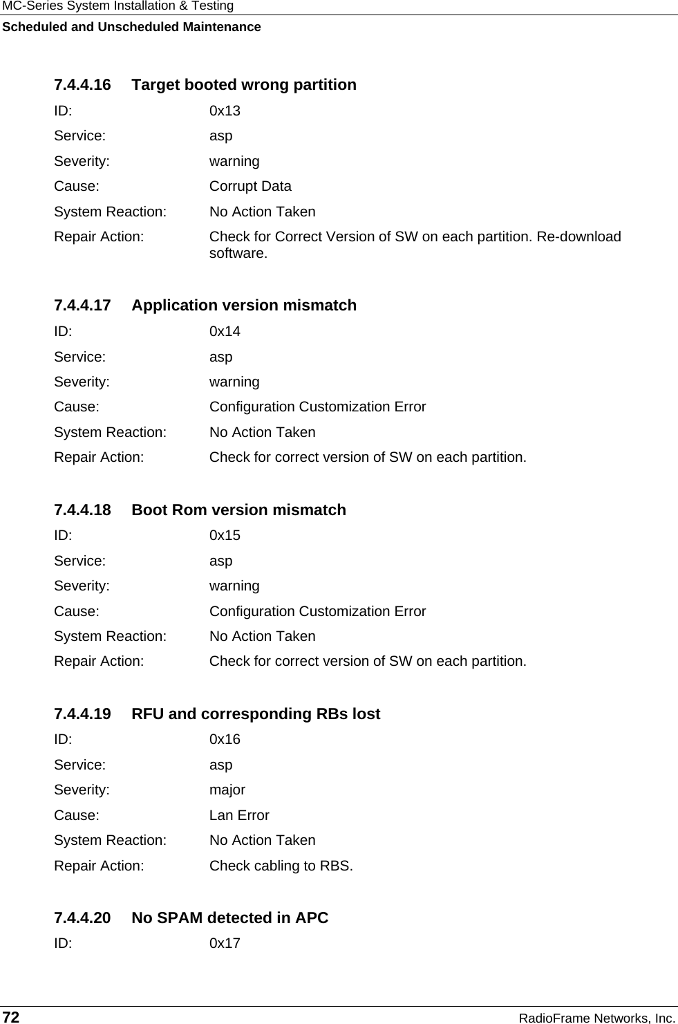
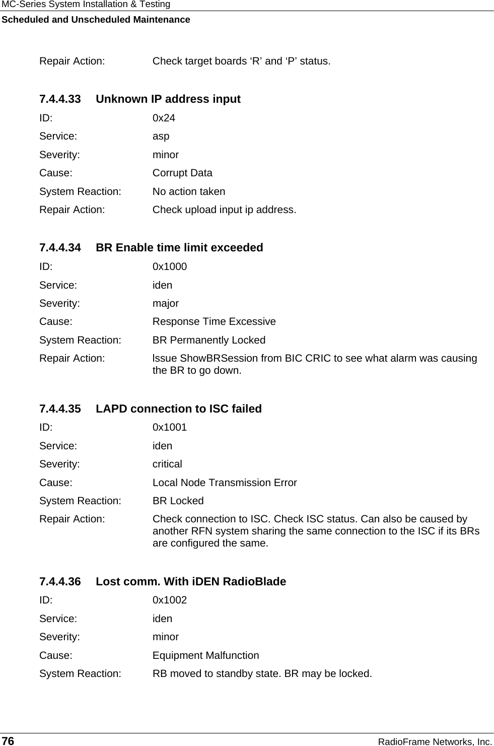
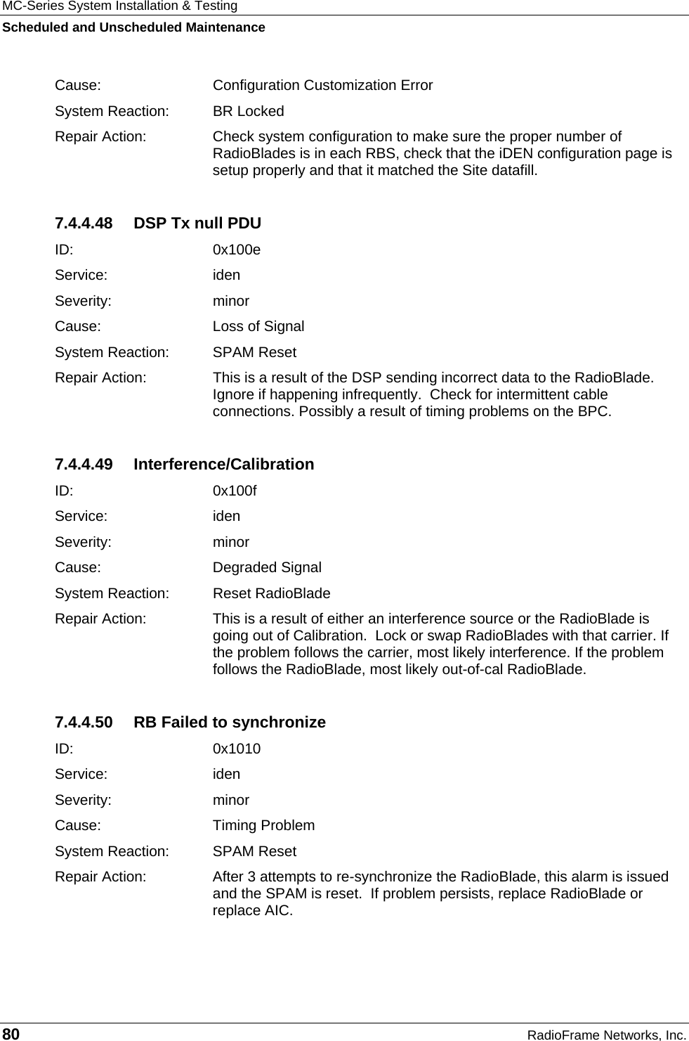
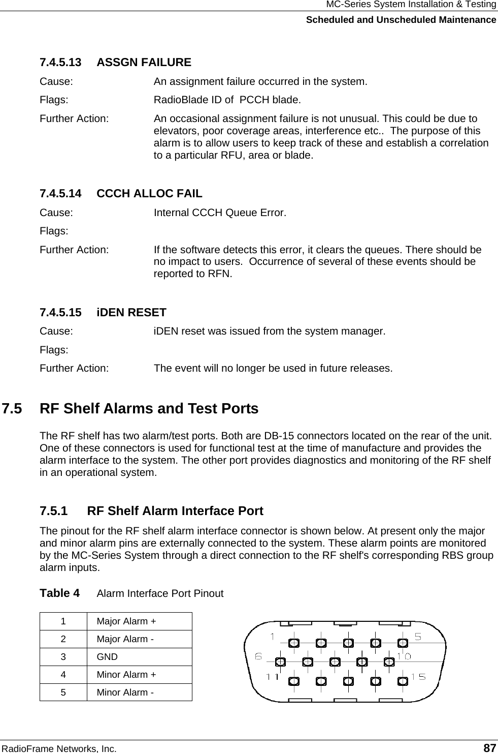
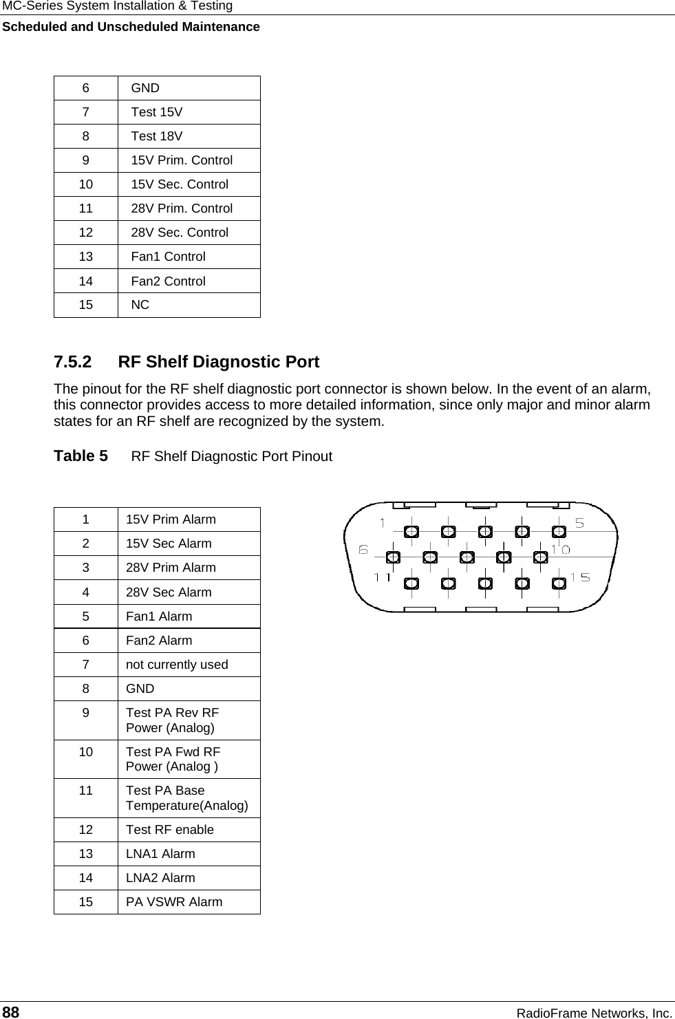
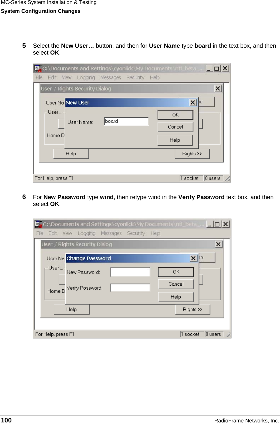
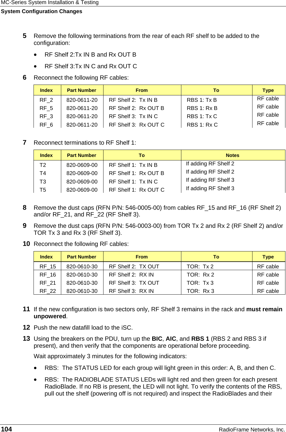
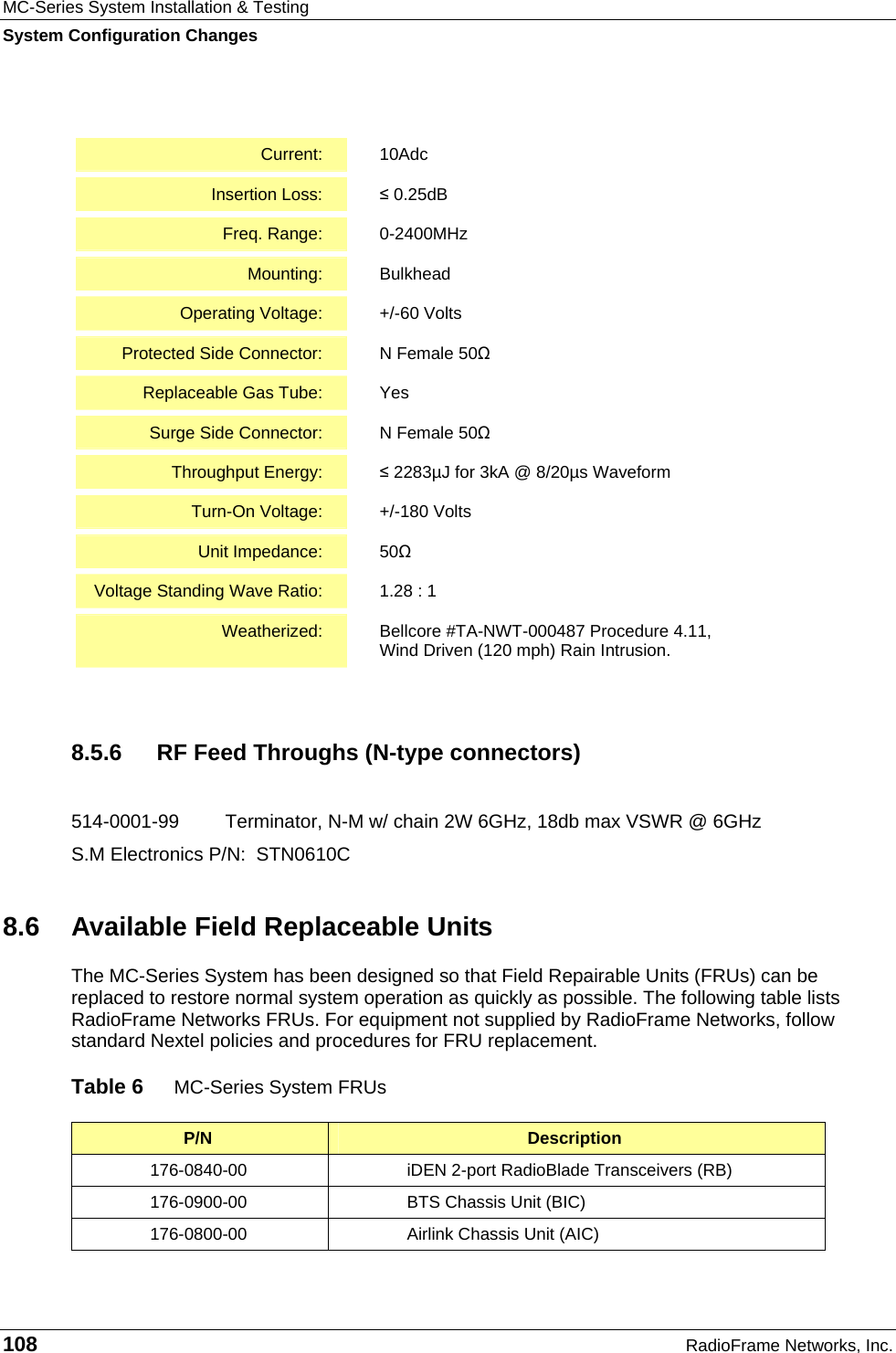
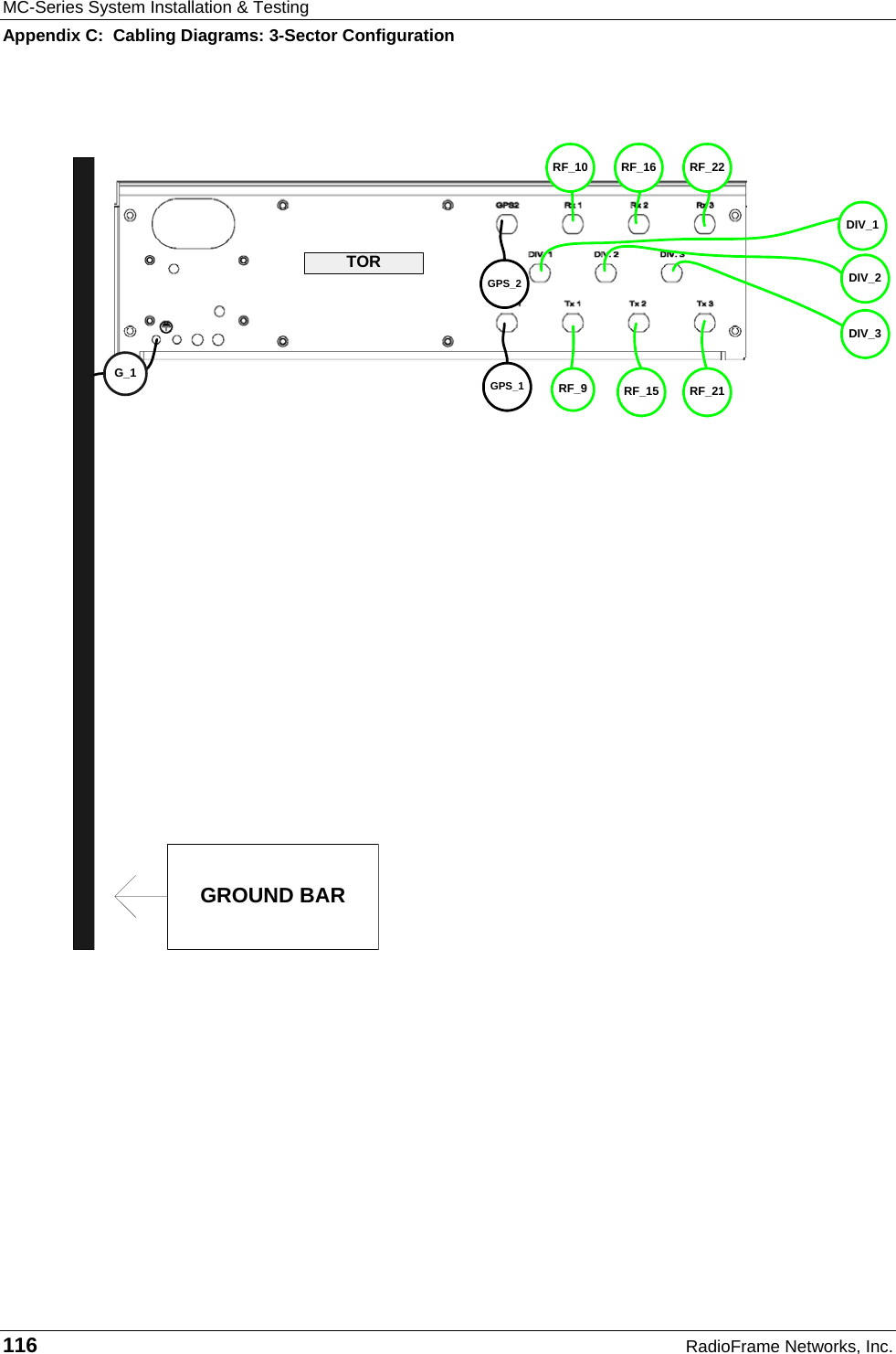
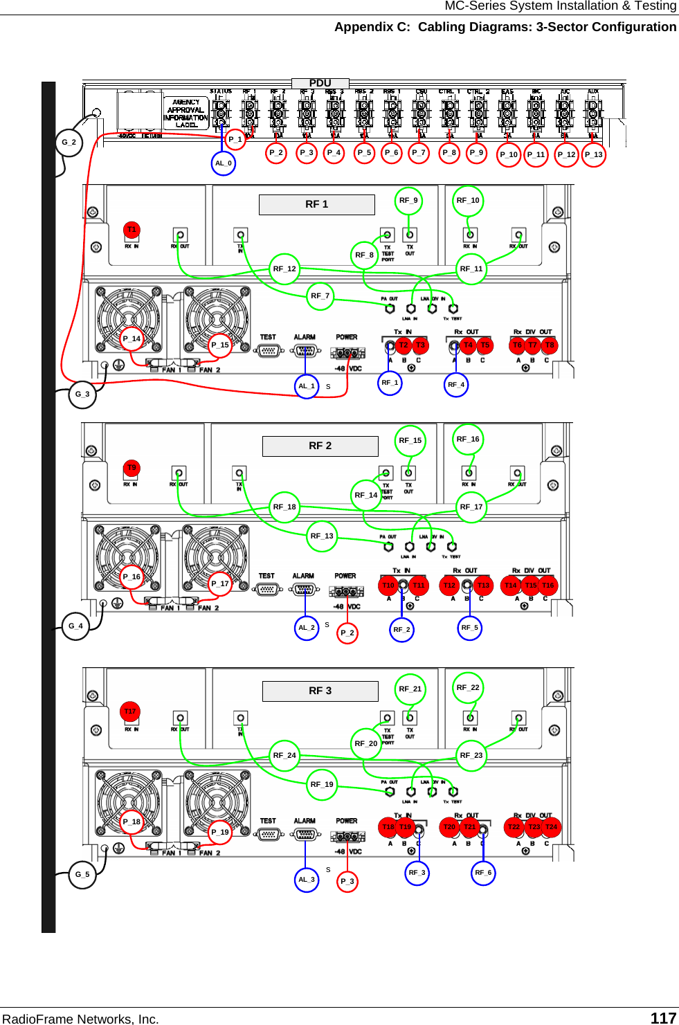
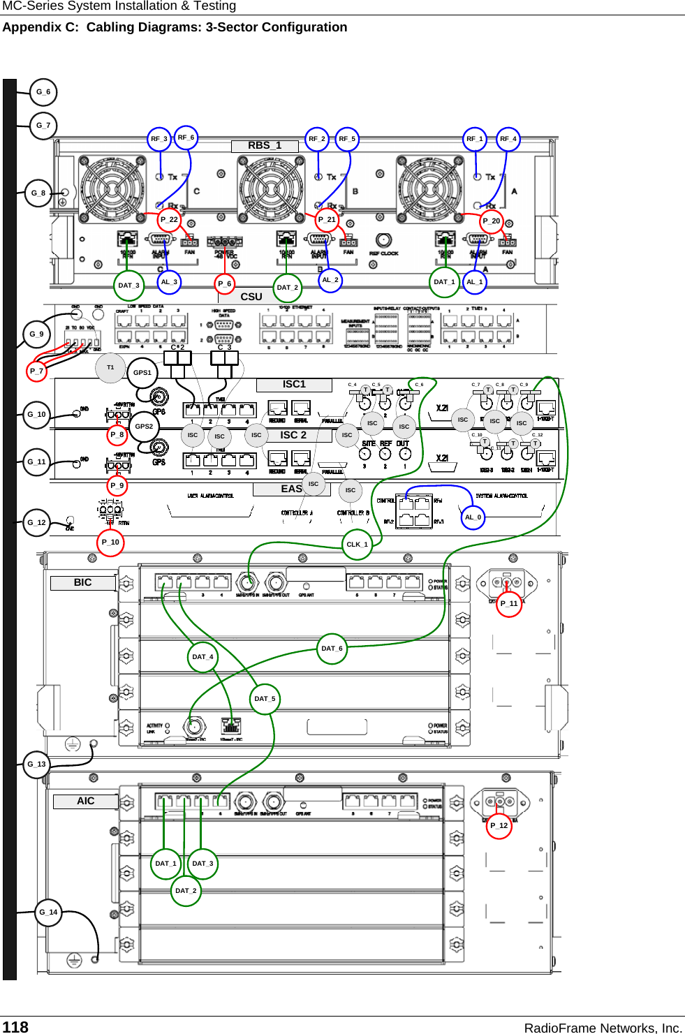
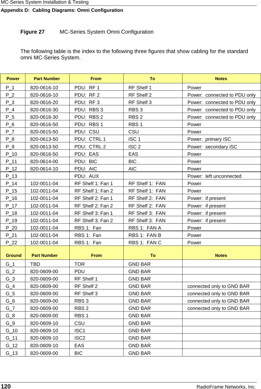
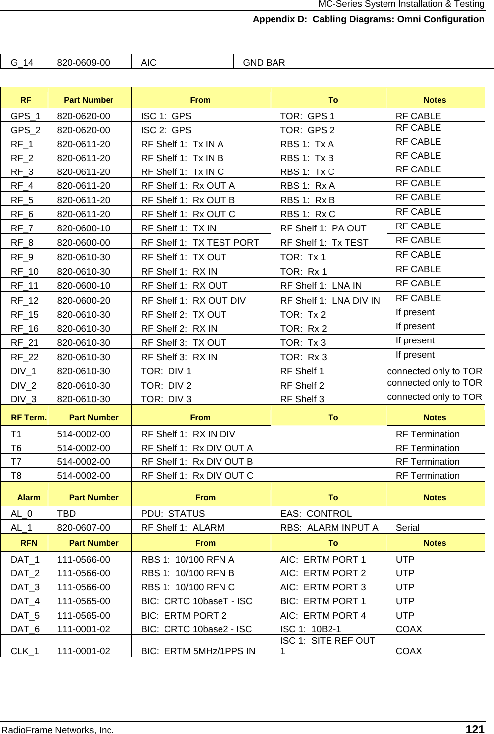
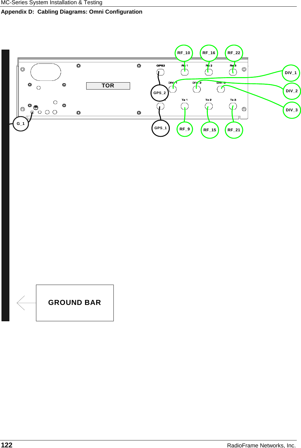
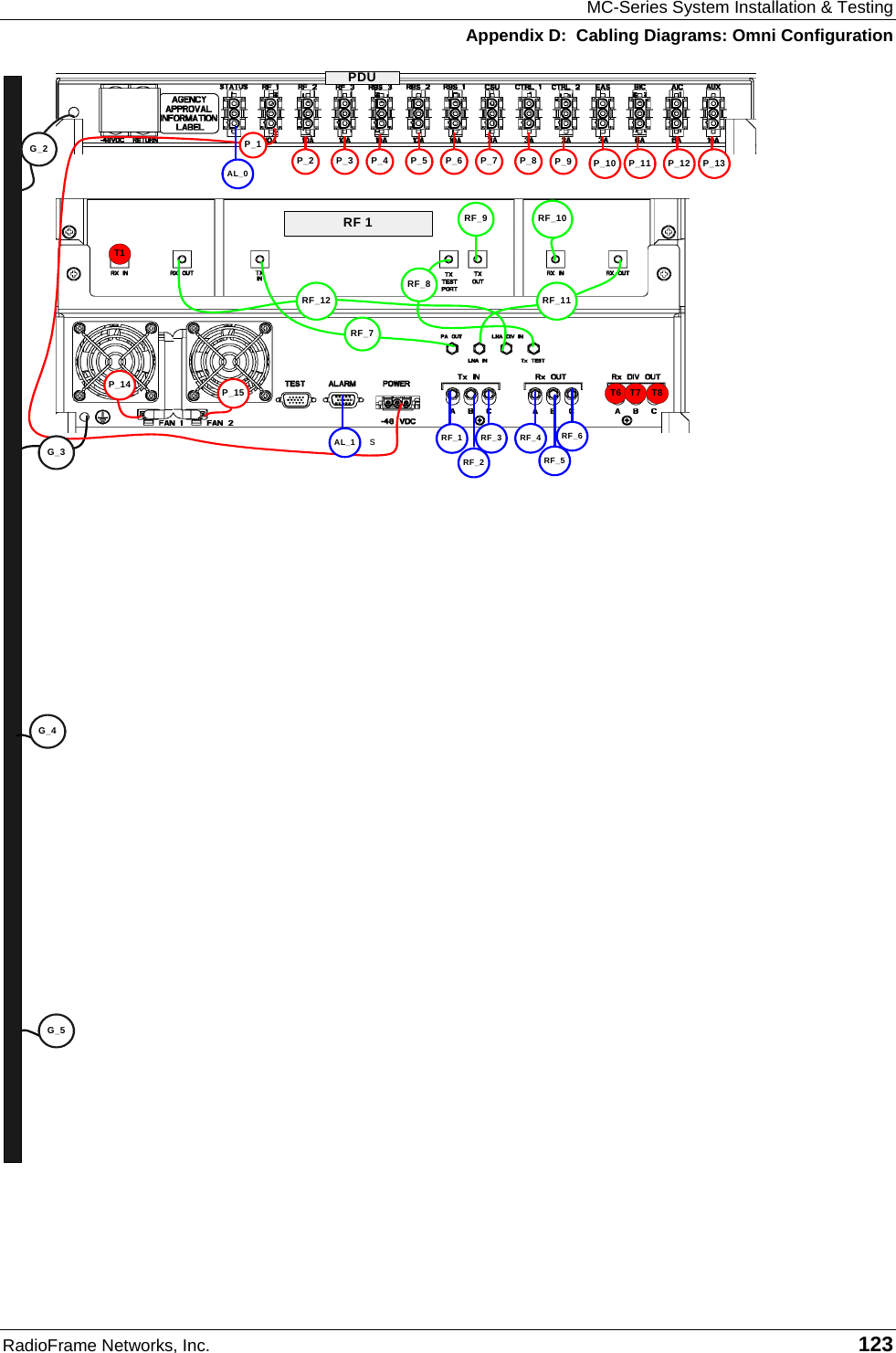
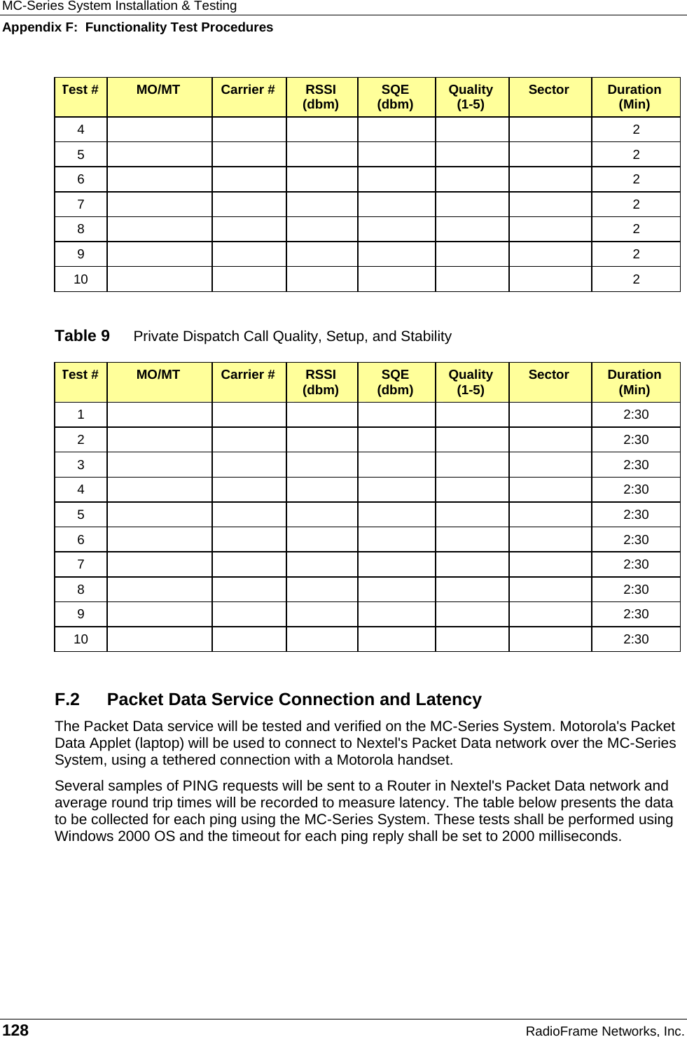
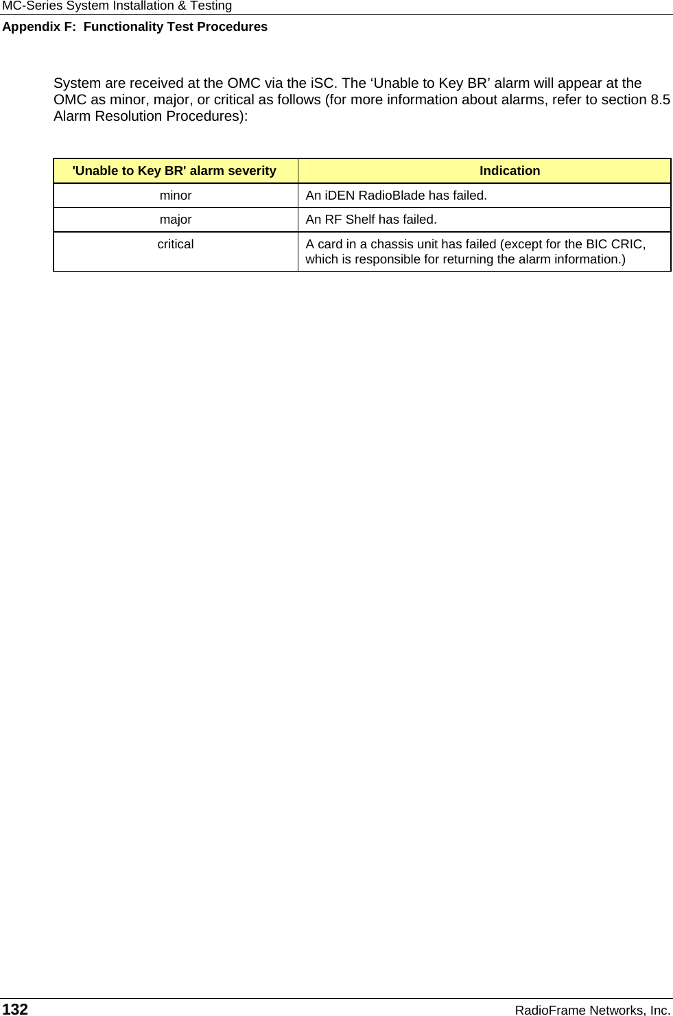
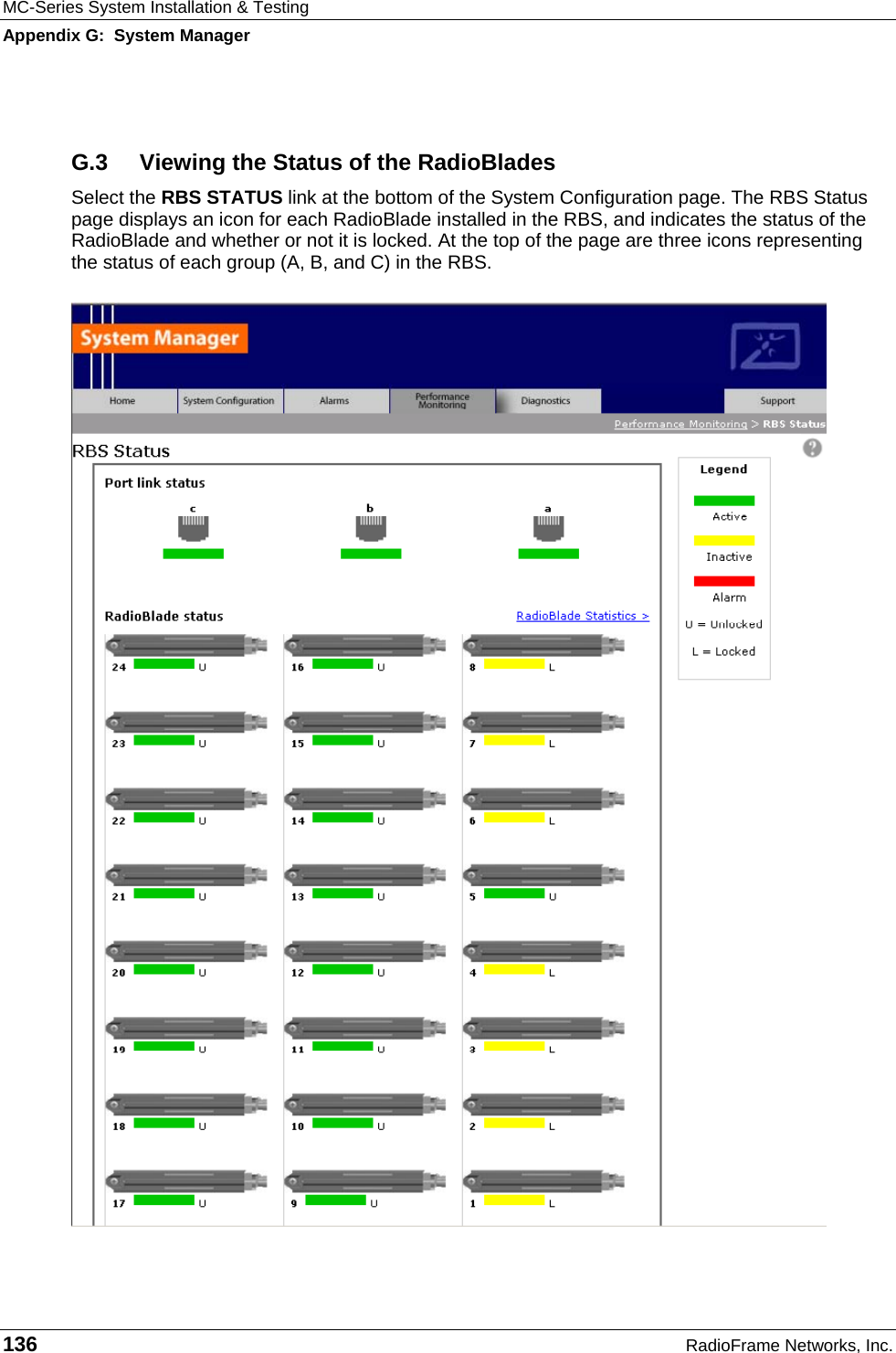
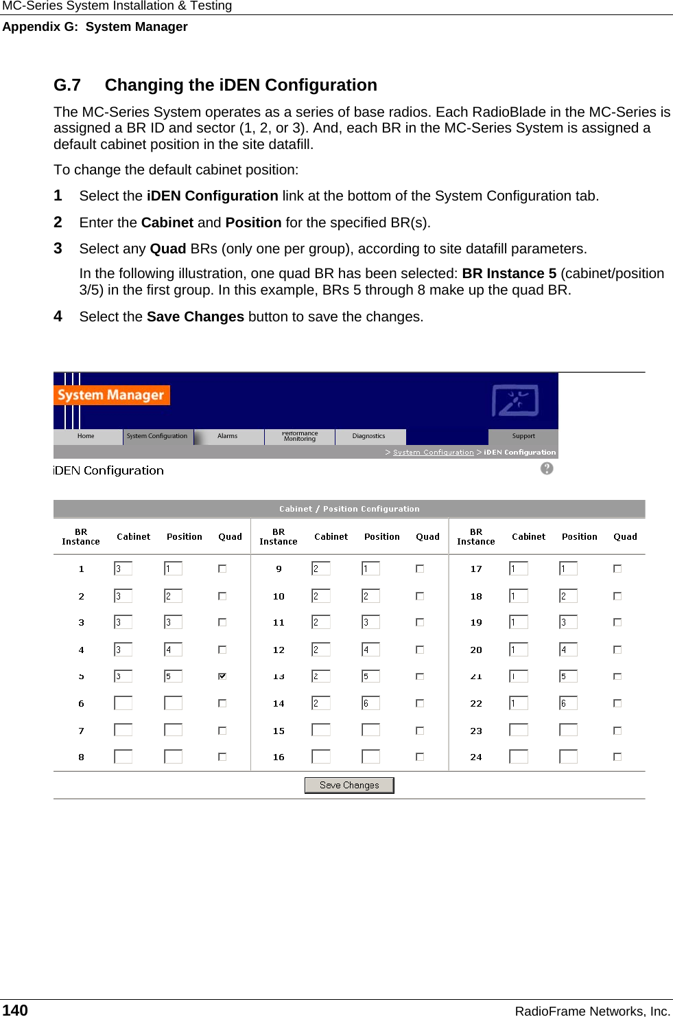
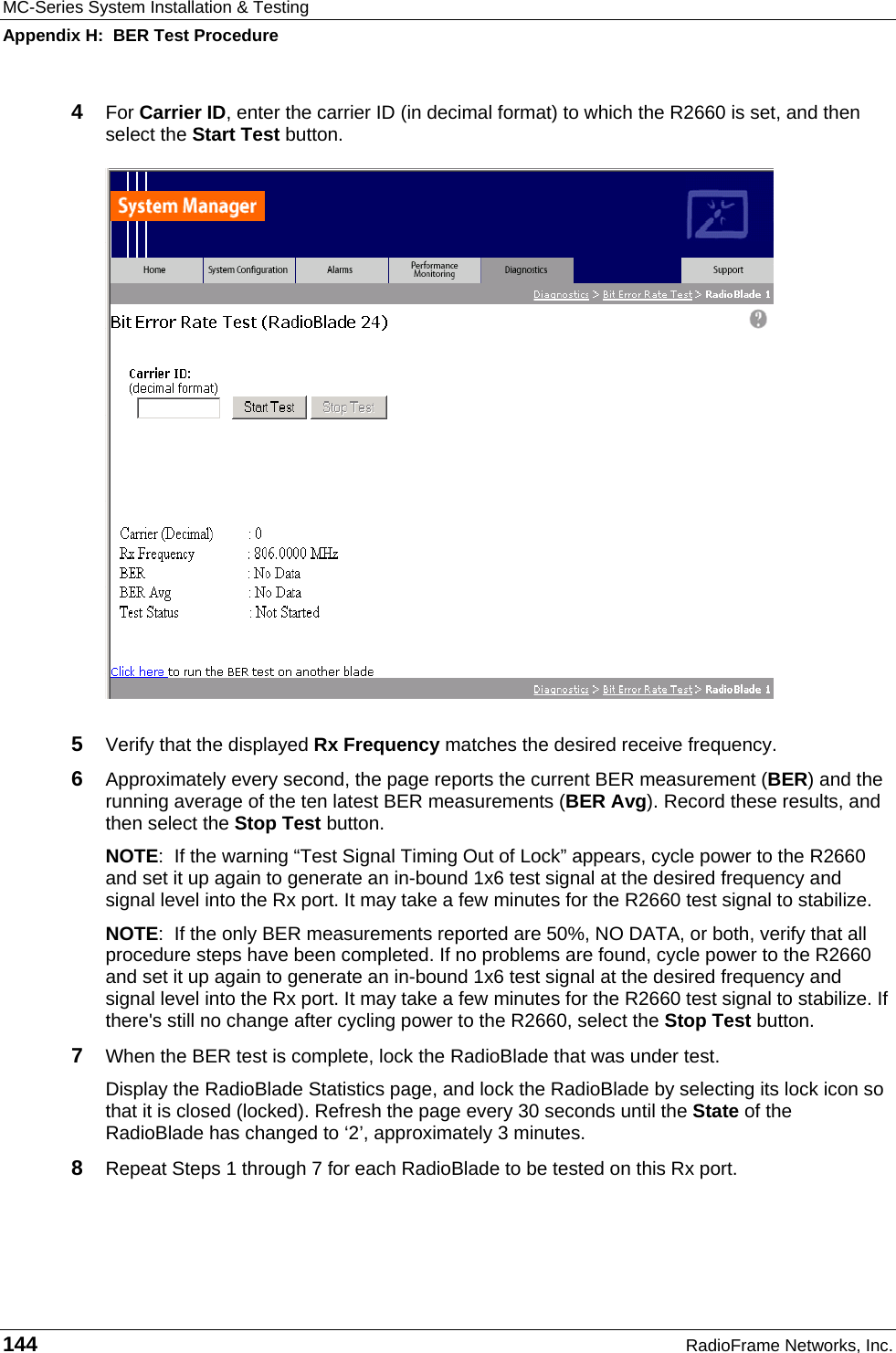
![MC-Series System Installation & Testing System Description 26 RadioFrame Networks, Inc. 2.5.4 Power Requirements Supplier Component Power RadioFrame Networks BIC -42 to -56 VDC AIC -42 to -56 VDC RBS -42 to -56 VDC RF Shelf -42 to -56 VDC PDU -42 to -56 VDC Non-RFN iSC-3 -40 to -60 VDC EAS -40 to -60 VDC CSU -40 to -60 VDC 2.5.5 Power Consumption* Assembly Qty Power[W] Per Assembly Total Power[W] Current[A] @ -48Vdc RF Shelf 3 68.0 216.0 4.4 RBS (24 RadioBlades) 1 67.2 67.2 1.4 BIC 1 110.0 110.0 2.3 AIC 1 115.2 115.2 2.4 ISC 2 24 48.0 1.0 EAS 1 19.2 19.2 0.4 CSU 1 40 40 0.8 TOTAL 615.6 12.7 * Panduit termination lugs are required for installation. 2.5.6 Grounding* Supplier Component Ground Resistance (ohms) RadioFrame Networks cabinet No greater than XX ohms * Termination lugs are required for installation.](https://usermanual.wiki/RadioFrame-Networks/MCSERIES10/User-Guide-523610-Page-32.png)