RadioFrame Networks MCSERIESHP10 MC Series High Power User Manual IGhp c
RadioFrame Networks, Inc MC Series High Power IGhp c
UserManual.wiki
>
RadioFrame Networks
>
MCSERIESHP10 User Manual
Users Manual
Navigation menu
Upload a User Manual
Namespaces
Wiki Guide
HTML
PDF
Info
Views
User Manual
Discussion / Help
Navigation


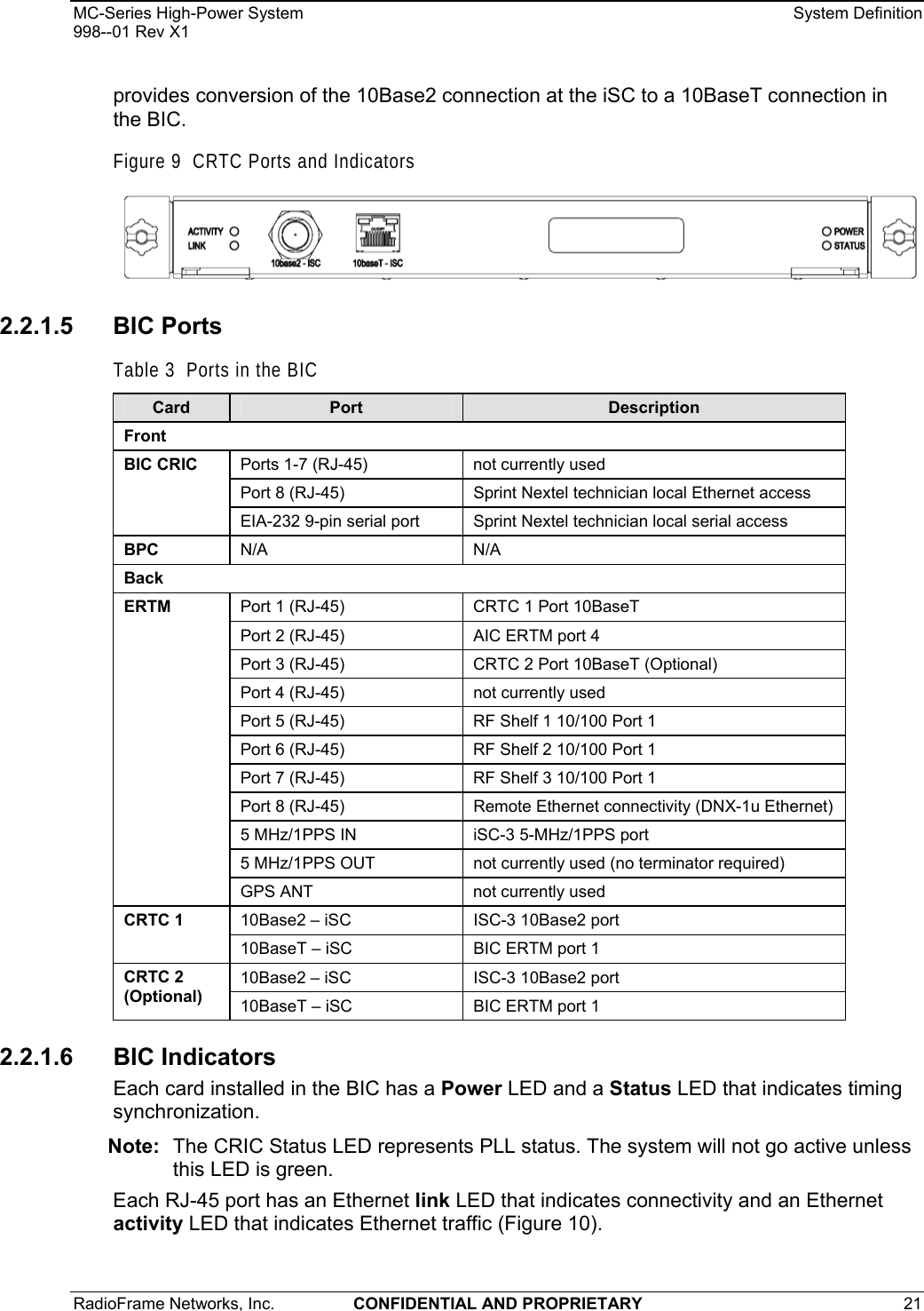
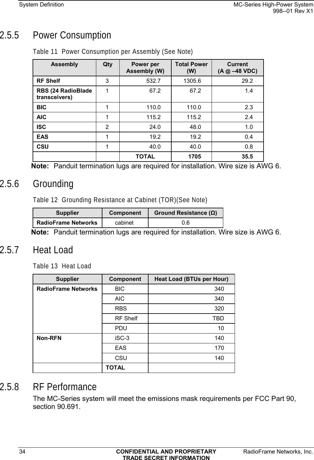

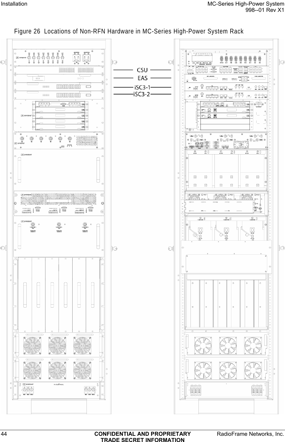
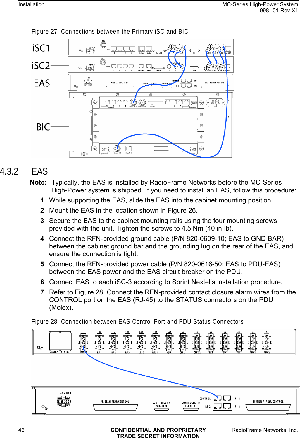
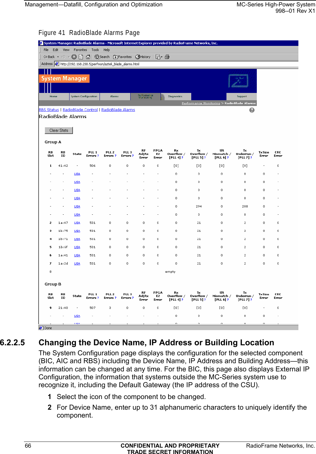
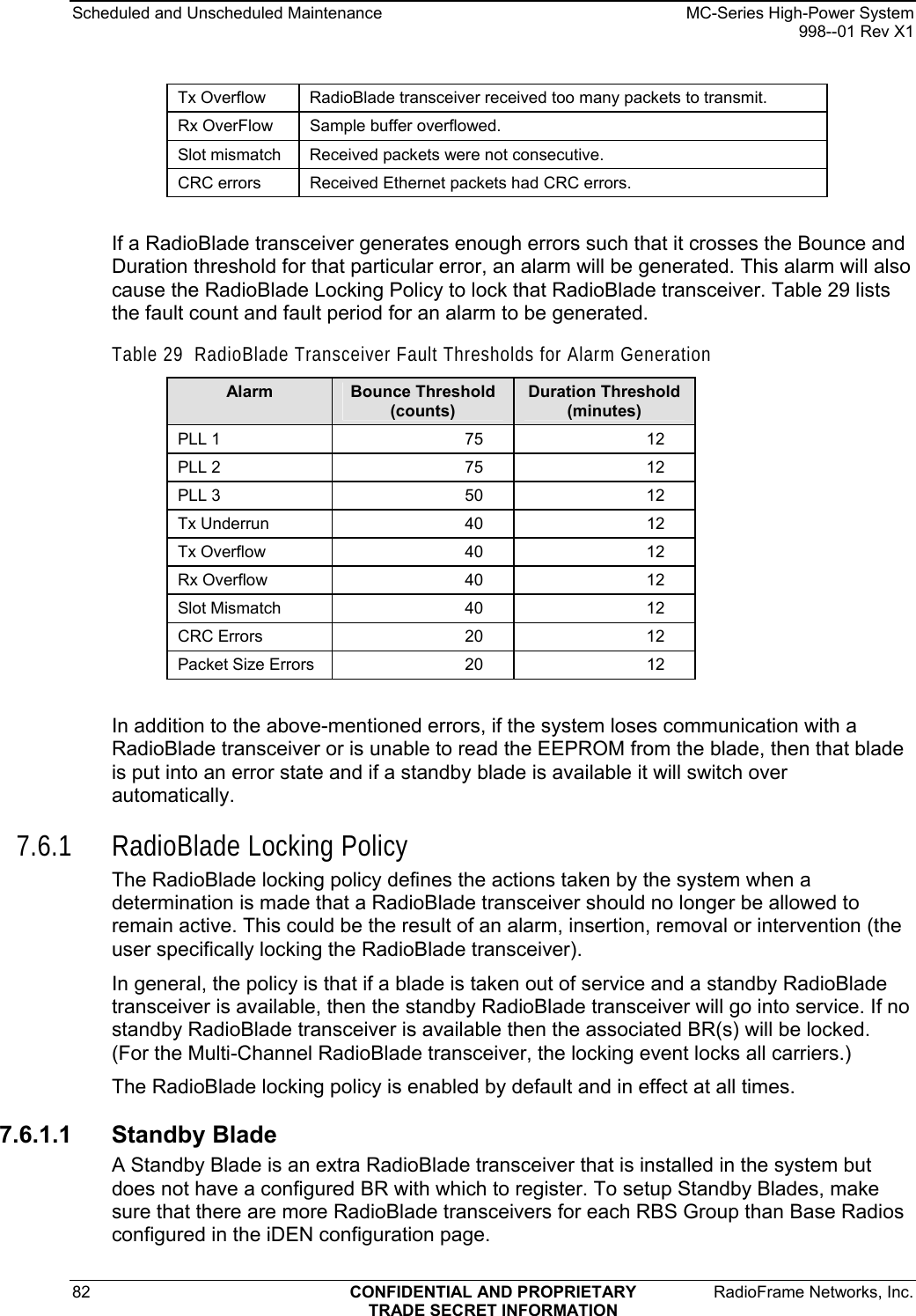
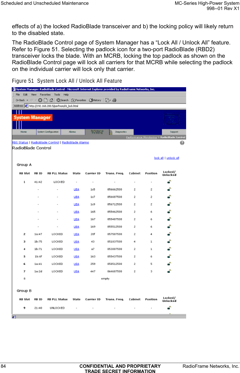
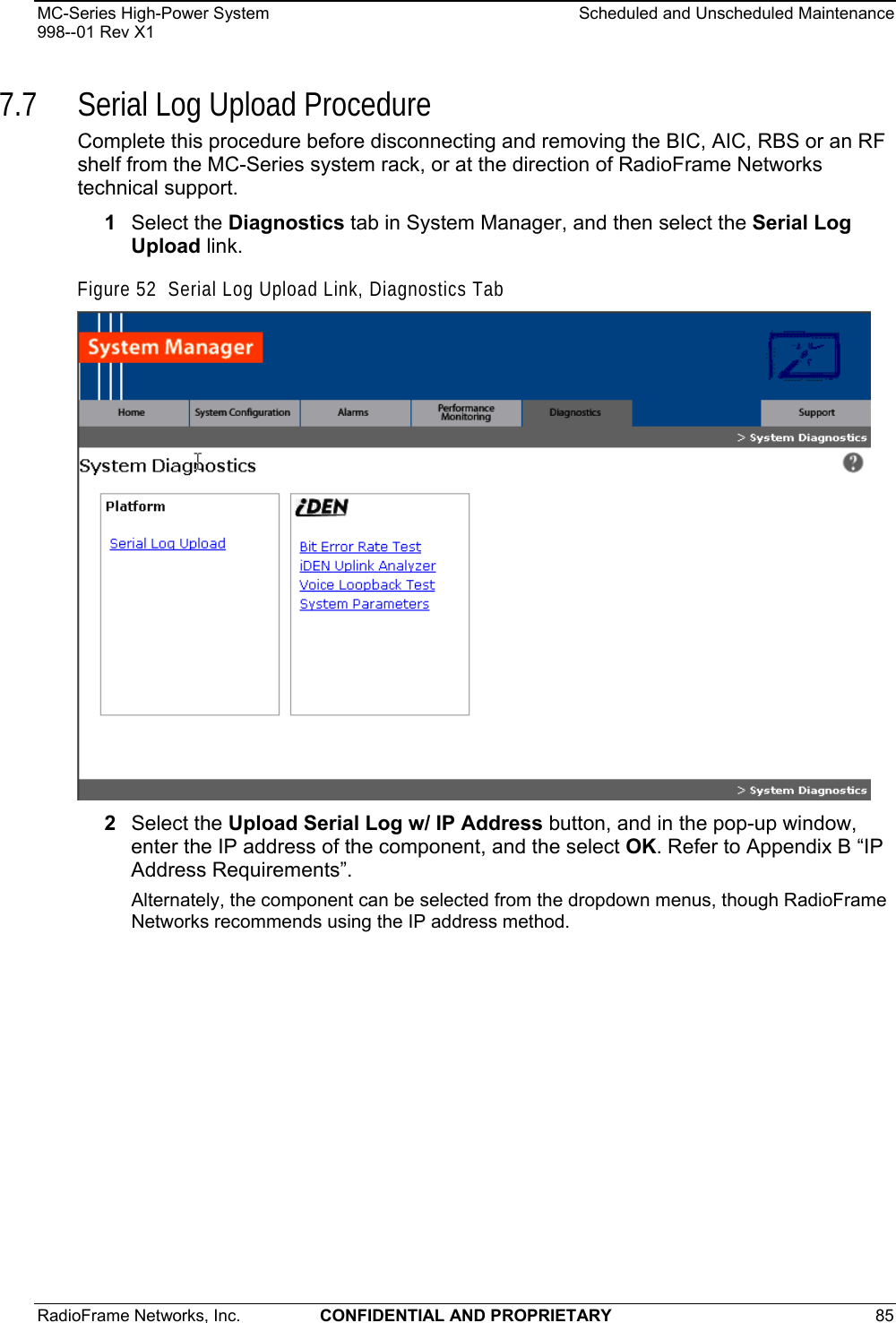
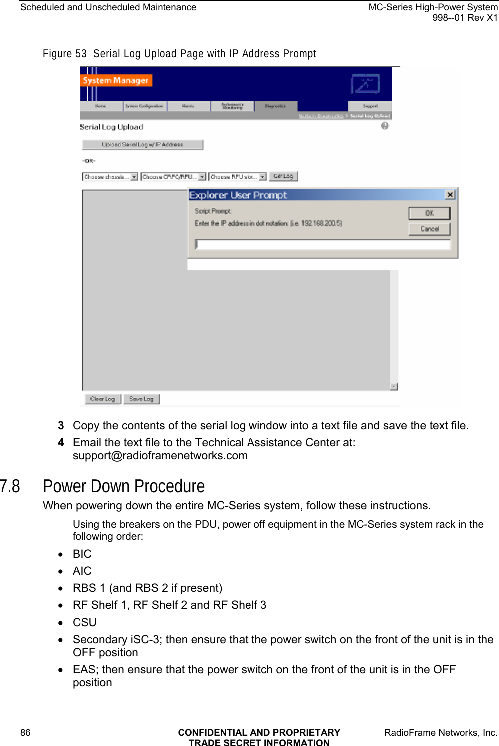
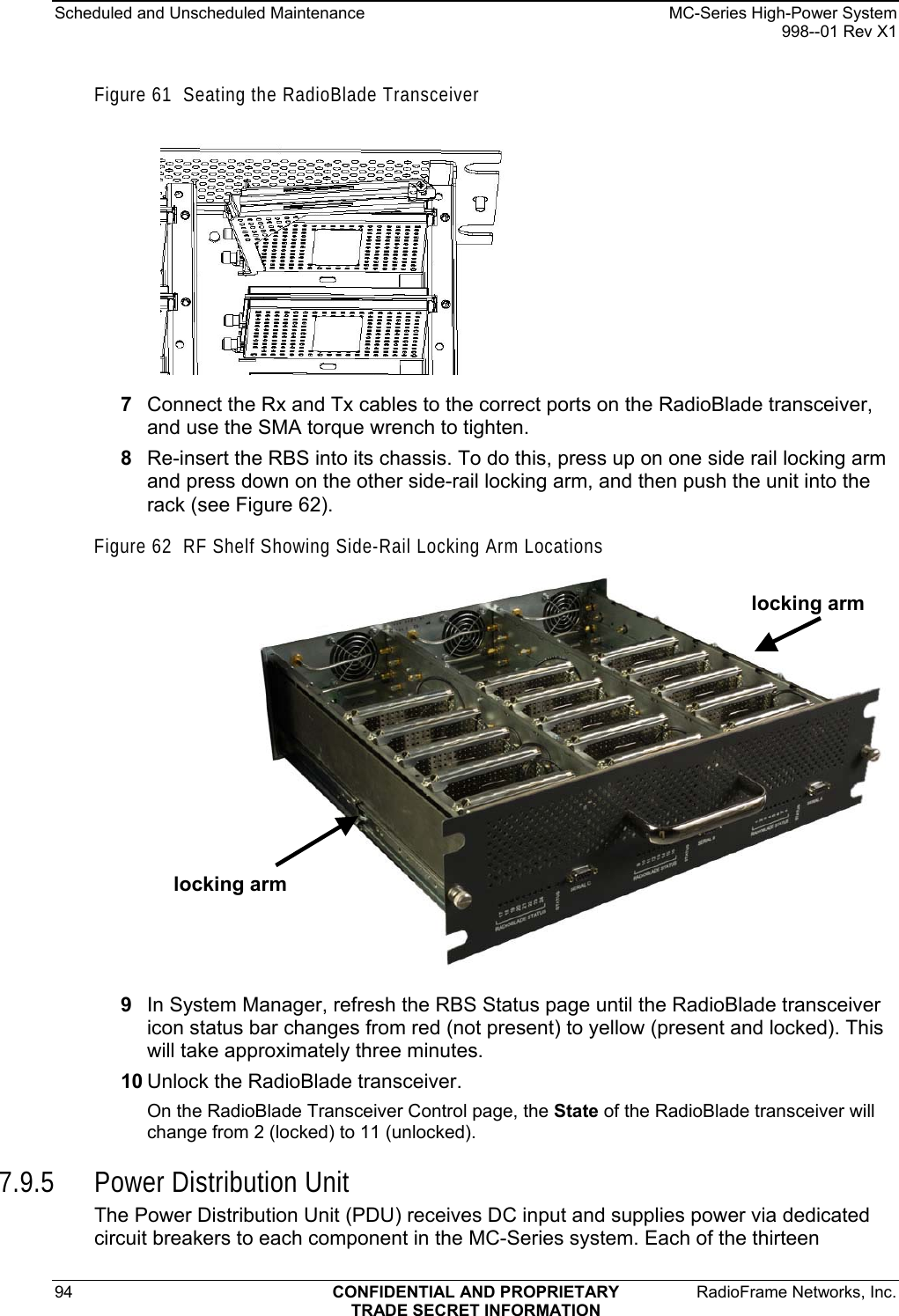
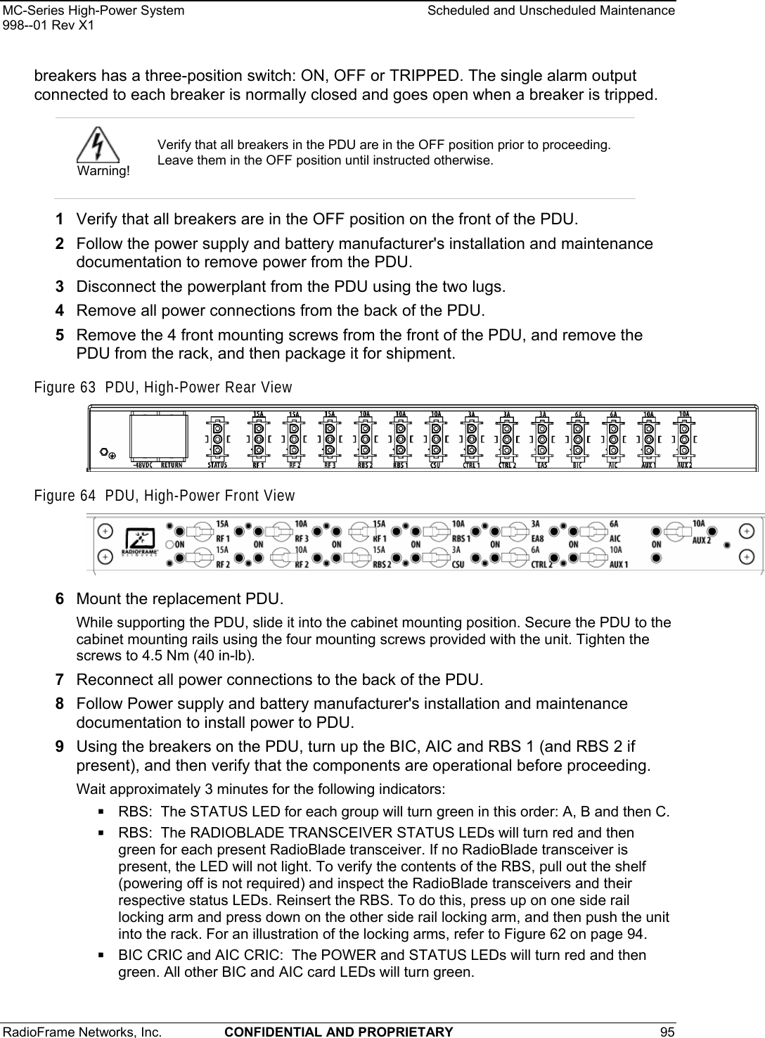
![MC-Series High-Power System Installation 998--01 Rev X1 RadioFrame Networks, Inc. CONFIDENTIAL AND PROPRIETARY 45 4.3.1 iSC-3s Note: Typically, the iSC-3s are installed by RadioFrame Networks before the MC-Series High-Power system is shipped. If you need to install an iSC-3, follow this procedure. 1 While supporting the iSC-3, slide the iSC-3 into the cabinet mounting position. 2 Mount the iSC-3 in the location shown in Figure 26. If necessary, install side rails in the mounting position in the rack. 3 Secure the iSC-3 to the cabinet mounting rails using the four mounting screws provided with the unit. Tighten the screws to 4.5 Nm (40 in-lb). 4 Connect the RFN-provided ground cable (P/N 820-0609-10; ISC1 to GND BAR) between the cabinet ground bar and the grounding lug on the rear of the iSC-3, and ensure the connection is tight. 5 Connect the RFN-provided power cable (P/N 820-0613-50; PDU-CTRL_1 to ISC1) between the iSC-3 power and the CTRL circuit breaker on the PDU (CTRL 1 for the primary iSC and CTRL 2 for the secondary iSC). 6 Repeat steps 1 through 4 to mount the secondary iSC-3 (cable labels will show ISC2 instead of ISC1). 7 Connect the two iSC-3s according to Sprint Nextel’s installation procedure. 8 Refer to Figure 27. Using the RFN-provided coax cable (P/N 111-0001-02; BIC-ERTM 5 MHz IN to ISC1 REF OUT-1), connect the primary iSC-3 port SITE REF OUT 1 [K] to the BIC ERTM port 5 MHz IN [L]. 9 Terminate the two remaining SITE REF OUT ports on the primary iSC-3, and terminate all three SITE REF OUT ports on the secondary iSC-3. 10 Using the RFN-provided coax cable (PN 111-0001-02; BIC-CRTC to iSC1 REF OUT-1), connect the primary iSC-3 port 10B2-1 to BIC CRTC port 10Base2 iSC. 11 Terminate the two remaining iSC-3 10B2 ports on the primary iSC-3, and terminate all three 10B2 ports on the secondary iSC-3. Note: Figure 27 does not show all cabling. For complete cabling information, refer to Appendix C “High-Power iDEN Microcell Rack Stack-Up, 3-Sector (Default) Configuration”.](https://usermanual.wiki/RadioFrame-Networks/MCSERIESHP10/User-Guide-773308-Page-45.png)