RadioFrame Networks MCSERIESSC MC Series Standard Capacity Base Station User Manual BOOK std cap
RadioFrame Networks, Inc MC Series Standard Capacity Base Station BOOK std cap
User Manual

RadioFrame Networks
02/13/2008
998-1019-01 Rev X1
MC-Series Standard Capacity system
Implementation Guide
Proprietary and Confidential Information For Customer and End User Use Only

©2008 RadioFrame Networks, Inc. MC-Series
For Customer and End User Use Only
MC-Series Standard Capacity system Implementation Guide 998-1019-01 Rev X1
©2008 RadioFrame Networks, Inc.
All rights reserved.
All trade names, trademarks, or registered trademarks are trade names, trademarks, or registered
trademarks of their respective companies.
Confidentiality
This document consists of information that is confidential and proprietary to RFN. Each reviewer of this document
agrees, with regard to such confidential and proprietary information, (1) to hold such information in strict
confidence until such information becomes publicly available through no fault or action of such reviewer, (2) if such
reviewer is an entity, to disclose such information only to those of its employees who have a need to know such
information in order to pursue a business opportunity with RFN relating to such information, and who have
executed confidentiality agreements with such reviewer sufficient to cover such information, (3) not to disclose
such information to any third party without the written consent of RFN, and (4) not to reproduce or use such
information except as necessary to pursue a business opportunity with RFN relating to such information.
Ownership
RFN owns all right, title and interest in and to the S-Series system, any products or other
commercializations thereof and any property rights related thereto (including, without limitation, any
and all patents, copyrights, trademarks, service marks, trade secrets and other intellectual property
and proprietary rights). RFN also owns all right, title and interest in and to the “S-Series” trademark.
Any licenses to such rights will only be granted pursuant to a separate agreement. No intellectual
property rights are granted in this document expressly, by implication or estoppel, or otherwise.
Copyrights and Trademarks
RadioFrame Networks is a trademark or service mark, and RadioFrame and the RadioFrame
Networks logo are registered trademarks of RadioFrame Networks, Inc. You may not use these or any
other RadioFrame Networks trademarks or service marks without the written permission of
RadioFrame Networks, Inc. All other trademarks and trade names are the property of their respective
owners. Throughout this publication, the terms RadioFrame Networks, RadioFrame and RFN signify
RadioFrame Networks, Inc.
MC-Series Standard Capacity system
©2008 RadioFrame Networks, Inc. All Rights Reserved. No part may be reproduced, in any media,
except as authorized by written permission of RadioFrame Networks, Inc.
Template History
This document is published with FrameMaker 7.2P158 using the following template releases:
Date FrameMaker Template Name Rev #
05/2007 7.2P158 Master Template Letter 2.1 (LTR)
7.2P158 Master Template A4 1.0 (A4)
For more information about this document, or to order additional copies, please contact:
RadioFrame Networks, Inc.
9461 Willows Road NE
Suite 100
Redmond, WA 98052
Attn: Technical Information Department
or E-mail your request to: techInfo@RadioFrameNetworks.com

Document Registration and Feedback ©2008 RadioFrame Networks, Inc. MC-Series
MC-Series Standard Capacity system Implementation Guide
998-1019-01 Rev X1
Document Registration and Feedback
Title: MC-Series Standard Capacity system Implementation Guide
Document Number: 998-1019-01 Revision Number: Rev X1
Publication Date: 2/18/2008
Please complete this form and return it to the Documentation Group to ensure that you receive
updates to this document. Fold this sheet and send it to the address on the back, or contact us via E-
Mail at techInfo@radioframenetworks.com.
Fill out your name and address or attach your business card.
Please tell us your initial impressions of this documentation.
Please take a few minutes to add any comments you feel will help us to improve the usability and
quality of this document. Attach additional sheets, if necessary.
Thanks for your help!
Name:_______________________________
Address:_____________________________
_______________________________________
_________________________________
Region: _____________________________
Office Phone ( )______________________
FAX: ( )____________________________
Cell Phone: ( )_______________________
Pager: ( ) __________________________
E-Mail Address _______________________
Yes No N/A
1. Does this document appear to provide the information you require?
2. Does the information appear to be presented in a logical manner?
3. Does this document need more diagrams or illustrations?
4. Is the format accessible and easy-to-use?
5. Do you expect to use this document on a regular basis?
6. How would you rate the usability of this document on a scale of 1-5
(1=excellent)

RadioFrame Networks, Inc.
9461 Willows Road NE Suite 100
Redmond, Washington 98052
Attn: Technical Information
Fold 1st
Fold 2nd, then staple (please, no tape)
Postage
Name CIty
Title State
Company Country
Address Postal Code

MC-Series ©2008 RadioFrame Networks, Inc. 1
For Customer and End User Use Only
MC-Series Standard Capacity system Implementation Guide
998-1019-01 Rev X1
Contents
Preface ............................................................................................................................. 1
Audience .................................................................................................................... 1
Purpose...................................................................................................................... 1
Scope......................................................................................................................... 1
Conventions ............................................................................................................... 1
Chapter 1 Introduction ......................................................................................... 1-1
1.1 Introduction................................................................................................... 1-3
1.2 References.................................................................................................. 1-3
1.3 Safety Precautions ...................................................................................... 1-3
Electrostatic discharge (ESD).................................................................. 1-3
Working near High Voltage Sources........................................................ 1-4
Further Safety Recommendations ........................................................... 1-4
1.4 System Definition ........................................................................................ 1-4
MC-Series Standard Capacity system Field Replaceable Unit Parts List ... 1-4
1.5 MC-Series Standard Capacity system Configuration .................................. 1-7
1.6 RadioFrame Networks Hardware ................................................................ 1-8
1.6.1 Airlink BTS Interface Chassis (ABIC)....................................................... 1-8
1.6.2 CRIC ...................................................................................................... 1-10
1.6.3 BPC........................................................................................................ 1-11
1.6.4 ERTM..................................................................................................... 1-11
1.6.5 CRTC..................................................................................................... 1-12
1.6.6 Diversity RadioBlade Shelf (DRBS)....................................................... 1-12
1.6.7 Multi-Channel RadioBlade (MCRB) Transceivers.................................. 1-15
1.6.8 MC-Series Standard Capacity RF Shelf ............................................... 1-18
1.6.9 Power Distribution Unit .......................................................................... 1-20
1.6.10 System Manager Software..................................................................... 1-21
1.7 MC-Series Standard Capacity system cabinet.......................................... 1-23
1.7.1 Air Conditioning...................................................................................... 1-23
1.8 Non-RadioFrame Networks Hardware (must be installed)........................ 1-23
1.8.1 integrated Site Controller (iSCIII (must be installed))............................. 1-23
1.8.2 Environmental Alarm System (EAS (must be installed))........................ 1-23
1.8.3 Channel Service Unit (CSU--(must be installed)) .................................. 1-24
1.8.4 GPS Antenna System (must be installed).............................................. 1-25
1.8.5 Powerplant (must be installed)............................................................... 1-25
Chapter 2 Specifications...................................................................................... 2-1

2 ©2008 RadioFrame Networks, Inc. MC-Series
Proprietary and Confidential Information
MC-Series Standard Capacity system Implementation Guide 998-1019-01 Rev X1
2.1 Physical Dimensions .................................................................................... 2-2
2.2 Weight ......................................................................................................... 2-2
2.3 Power Specifications................................................................................... 2-2
2.3.1 Power Requirements ............................................................................... 2-2
2.3.2 Power Consumption ................................................................................ 2-3
2.3.3 Grounding................................................................................................ 2-3
2.3.4 Heat Load ................................................................................................ 2-4
2.4 Performance Specifications......................................................................... 2-4
Operating Frequency Bands.................................................................... 2-4
RF Performance Requirements............................................................... 2-4
2.4.1 Receiver Performance Summary............................................................. 2-5
2.4.2 Transmitter Performance Summary......................................................... 2-5
2.4.3 Tx Power Out........................................................................................... 2-5
2.4.4 Spurious RF Emissions ........................................................................... 2-6
2.5 Environmental Equipment Specifications.................................................... 2-6
2.6 Compliance ................................................................................................. 2-6
Chapter 3 Pre-Installation .................................................................................... 3-1
3.1 Pre-Installation Requirements...................................................................... 3-3
3.2 Site Planning ............................................................................................... 3-3
3.2.1 Space Requirements ............................................................................... 3-3
3.2.2 Anchoring................................................................................................. 3-3
3.2.3 Seismic Zone Installation......................................................................... 3-4
3.2.4 Cooling of Equipment .............................................................................. 3-4
3.2.5 Power....................................................................................................... 3-5
3.2.6 Grounding................................................................................................ 3-5
3.2.7 GPS Antennas......................................................................................... 3-5
3.2.8 T1 Service................................................................................................ 3-5
3.2.9 Alarm Blocks............................................................................................ 3-6
3.2.10 Environmental Alarm System (EAS)........................................................ 3-6
3.3 Scheduling / Logistics.................................................................................. 3-6
3.4 iDEN Configuration...................................................................................... 3-7
3.4.1 Cabinet and Position Settings.................................................................. 3-7
3.4.2 BRs.......................................................................................................... 3-7
3.4.3 Sectorization............................................................................................ 3-7
3.5 Site Inspection............................................................................................. 3-7
3.6 Receipt of Equipment.................................................................................. 3-8
RadioFrame Networks............................................................................. 3-8
Non-RadioFrame Networks ..................................................................... 3-8
3.6.1 Equipment Inspection .............................................................................. 3-8
3.6.2 Equipment Inventory................................................................................ 3-8
Chapter 4 Installation Process ............................................................................ 4-1
4.1 Mounting the MC-Series Standard Capacity system cabinet....................... 4-2
4.1.1 iSCIII........................................................................................................ 4-4
4.1.2 EAS.......................................................................................................... 4-5
4.1.3 CSU ......................................................................................................... 4-6

MC-Series ©2008 RadioFrame Networks, Inc. 3
For Customer and End User Use Only
MC-Series Standard Capacity system Implementation Guide
998-1019-01 Rev X1
4.2 Mounting Auxiliary Equipment..................................................................... 4-7
4.3 Cabinet-to-Site Cabling ............................................................................... 4-8
4.3.1 Matching Terminals for PDU and Ground................................................ 4-8
4.3.2 GPS surge arrestor.................................................................................. 4-8
4.3.3 Tx/Rx Surge Suppressor.......................................................................... 4-9
4.3.4 RF Feed-Throughs (N-type connectors).................................................. 4-9
4.3.5 Grounding .............................................................................................. 4-10
4.3.6 T1/E1 ..................................................................................................... 4-10
4.3.7 GPS Surge Arrestor............................................................................... 4-10
4.3.8 EAS Alarm Cabling ................................................................................ 4-11
4.3.9 RF (Tx / Rx and Rx diversity)................................................................. 4-11
4.3.10 Power..................................................................................................... 4-11
Chapter 5 Initial Power-up.................................................................................... 5-1
5.1 Initial Powering Procedure ........................................................................... 5-2
5.2 System Setup .............................................................................................. 5-3
5.3 Management—Datafill, Configuration and Optimization ............................. 5-8
5.3.1 Datafill...................................................................................................... 5-8
5.3.2 Parameters that Do Not Apply ................................................................. 5-9
5.3.3 Recommended Datafill Parameters......................................................... 5-9
5.3.4 rxTxGain = 0 ............................................................................................ 5-9
5.3.5 defaultTxPower...................................................................................... 5-10
5.4 System Manager, Configuration, and Optimization................................... 5-10
5.4.1 Navigating System Manager.................................................................. 5-10
5.5 Functionality Test ...................................................................................... 5-13
5.6 Configuring the MC-Series Standard Capacity system ............................. 5-14
5.6.1 Navigating the System Configuration..................................................... 5-14
5.7 Optimization Procedures........................................................................... 5-24
5.7.1 Local Performance Monitoring............................................................... 5-24
5.7.2 iDEN Uplink Analysis ............................................................................. 5-26
Chapter 6 System Configuration Changes.........................................................6-1
6.1 Upgrading MC-Series Standard Capacity system Software......................... 6-2
6.1.1 Download MC-Series Standard Capacity system Software to the Laptop 6-2
6.1.2 Download FTP Server Software to the Laptop Computer........................ 6-2
6.2 Update the MC-Series Standard Capacity system Software....................... 6-8
6.2.1 Verify the Software Download................................................................ 6-11
6.3 Rollback to the previous version of software............................................. 6-12
6.4 Performing a System Reset ...................................................................... 6-12
Chapter 7 Final Checkout.....................................................................................7-1
7.1 Final Checkout procedures ..........................................................................7-2
7.1.1 Prerequisites............................................................................................ 7-2
Required Tools:........................................................................................ 7-2
7.1.2 Checkout Procedures ............................................................................. 7-3
Chapter 8 Troubleshooting the MC-Series Standard Capacity system........... 8-1
8.1 Maintenance................................................................................................. 8-2
8.1.1 Annual Maintenance ................................................................................ 8-2

4 ©2008 RadioFrame Networks, Inc. MC-Series
Proprietary and Confidential Information
MC-Series Standard Capacity system Implementation Guide 998-1019-01 Rev X1
8.2 Troubleshooting Guidelines......................................................................... 8-2
8.3 Hardware Alerts........................................................................................... 8-3
8.3.1 Fault Indications....................................................................................... 8-3
8.3.2 ABIC Indicators........................................................................................ 8-3
8.3.3 DRBS Indicators ...................................................................................... 8-4
8.3.4 RF Shelf Indicators .................................................................................. 8-4
8.4 Software Alerts............................................................................................ 8-5
System Manager Alarms ......................................................................... 8-5
8.4.1 Viewing System Manager Alarms............................................................ 8-5
8.4.2 OMC Alarm Code .................................................................................... 8-8
iDEN Alarm Code 4133 ........................................................................... 8-9
8.4.3 System Manager Alarms ....................................................................... 8-10
8.5 RadioBlade Transceiver Alarm Handling .................................................. 8-11
8.6 RadioBlade Troubleshooting..................................................................... 8-12
8.6.1 RadioBlade Locking Policy .................................................................... 8-12
8.6.2 Standby Blade ....................................................................................... 8-12
8.6.3 Locking Policy for RadioBlade Transceiver with Errors ......................... 8-13
8.7 Serial Log Upload Procedure .................................................................... 8-15
Chapter 9 Field Replaceable Unit (FRU) Procedures ........................................ 9-1
9.1 Field Replaceable Units (FRUs)................................................................... 9-2
9.1.1 Field Replaceable Unit (FRU) Policy ....................................................... 9-2
9.1.2 Field Replaceable Units (FRUs), Parts and Extra Supplies..................... 9-3
9.2 Power Down Procedure .............................................................................. 9-3
9.3 RF Shelf ...................................................................................................... 9-5
9.3.1 RF Shelf Replacement Procedure........................................................... 9-5
9.3.2 Replacing a Fan in the RF Shelf.............................................................. 9-7
9.4 Replacing a Chassis: ABIC or DRBS.......................................................... 9-8
9.4.1 ABIC ........................................................................................................ 9-8
9.4.2 DRBS..................................................................................................... 9-10
9.5 ABIC– FRU Replacement Procedure........................................................ 9-12
9.5.1 Replacing the CRIC............................................................................... 9-12
9.5.2 BPC ....................................................................................................... 9-14
9.5.3 ERTM..................................................................................................... 9-16
9.5.4 CRTC..................................................................................................... 9-18
9.6 Adding or Removing RadioBlade Transceivers......................................... 9-20
9.7 RadioBlade Transceiver Replacement...................................................... 9-20
9.8 Power Distribution Unit (PDU)................................................................... 9-24
9.8.1 PDU ....................................................................................................... 9-25
Appendix A General Safety Information ...............................................................A-1
A.1 Static Sensitive Precautions ........................................................................A-1
A.2 Safety Warnings ..........................................................................................A-2
A.3 Safety Warnings per Cabinet mount Instructions ........................................A-2
Reduced Air Flow ....................................................................................A-2

MC-Series ©2008 RadioFrame Networks, Inc. 5
For Customer and End User Use Only
MC-Series Standard Capacity system Implementation Guide
998-1019-01 Rev X1
Mechanical Loading .................................................................................A-3
Circuit Overloading ..................................................................................A-3
Reliable Earthing ......................................................................................A-3
A.4 Overall Recommendations ..........................................................................A-3
Appendix B IP Address Requirements ..................................................................B-1
B.1 IP Address Requirements ...........................................................................B-1
Appendix C Functionality Test Procedures ..........................................................C-1
C.1 Interconnect and Dispatch Setup and Voice Quality Testing ......................C-1
C.2 Packet Data Service Connection and Latency ............................................C-3
C.3 Short Message Service ...............................................................................C-4
C.4 Handover and Cell Reselection ...................................................................C-4
C.5 Interconnect Connection Stability and SQE Performance ...........................C-5
C.6 Dispatch Connection Stability ......................................................................C-5
C.7 Idle SQE Testing and Validation .................................................................C-6
C.8 System Self-Recovery Test .........................................................................C-6
C.9 Packet Data Stability and Throughput .........................................................C-7
C.10 Validation of 'Unable to Key BR' Alarm .......................................................C-7
Appendix D Tx / Rx Curves ....................................................................................D-1
D.1 800E Tx Filter Response .............................................................................D-1
Appendix E BER Test Procedure ...........................................................................E-1
E.1 Bit Error Rate (BER) Diagnostic Test ..........................................................E-1
E.2 Prerequisites for Testing .............................................................................E-1
E.3 Test Tool .....................................................................................................E-2
E.4 Testing Strategy ..........................................................................................E-2
E.4.1 BER Test on an MCRB.............................................................................E-2
E.5 Equipment Connection/Setup ......................................................................E-3
E.5.1 Motorola R2660 ........................................................................................E-4
E.6 BER Test Procedure ...................................................................................E-4
E.7 RadioBlade Transceiver Pre-Test ...............................................................E-5
E.7.1 RadioBlade Transceiver BER Test ...........................................................E-7
E.8 Equipment Disconnection ..........................................................................E-11
E.9 BER Test Notes Master .............................................................................E-11
Appendix F Dangerous RF Emissions Precautions ............................................F-1

6 ©2008 RadioFrame Networks, Inc. MC-Series
Proprietary and Confidential Information
MC-Series Standard Capacity system Implementation Guide 998-1019-01 Rev X1
Appendix G Repair and Technical Support ......................................................... G-1
G.1 RadioFrame Networks Support .................................................................. G-1
G.1.1 Technical Support.................................................................................... G-1
Glossary.....................................................................................................Glossary-1
Revision History...........................................................................Revision History-1

MC-Series Standard Capacity system
998-1019-01 Rev X1
MC-Series ©2008 RadioFrame Networks, Inc. 1
For Customer and End User Use Only
Preface
Audience
This document is written for the technical staff who are standards for
installing, modifying and maintaining RadioFrame Networks equipment
at the customer sites. All specifications and requirements pertain to
MC-Series Standard Capacity (MCSC) system equipment operating in
800E band with medium power amplification, as required in some
integrated Digital Enhanced Network (iDEN) installations.
The user of this document should be proficient with the following:
• Motorola Generation 3 Site Controller System
• iDEN OMC-R Configuration Management procedures
• Channel Service Unit (CSU) manufacturer’s specifications
• Power supply and battery manufacturer's specifications
• General Dynamics R2660 Series Communications System
Analyzer
• Fixed Network Equipment (FNE) Quality Standards
• National Electrical Code (NEC) standards
• National Fire Protection Associations (NFPA) Code 70
• ASTM (American Society For Testing and Materials)
• Bellcore Technical Specifications
• Electrostatic discharge (ESD) standards and procedures
Purpose
The purpose of this document is to provide an overview of the
RadioFrame Networks equipment and describes standards for
installing, modifying and maintaining RadioFrame Networks equipment
at the i customer sites.
Scope
This document provides instructions fro installing and operating
RadioFrame equipment.
Conventions
The following font and style conventions are used throughout this

MC-Series Standard Capacity system 998-1019-01 Rev X1
2 ©2008 RadioFrame Networks, Inc. MC-Series
Proprietary and Confidential Information
document.
Convention... Used to Indicate...
Courier fixed-pitch font,
non-bold Filenames, pathnames, scripts, screen displays (shown
boxed), and lines of code
Courier fixed-pitch font,
bold Text to be entered as instructed in a procedure
Italics/Underline Menu options as they appear on the screen
ALL CAPITALS Keyboard key names, such as ENTER or CTRL
The term enter The user should type the information and press ENTER
when completed
The term type The user should type the information but should not
press ENTER when completed
Commands
Commands that you enter in are preceded by a
<value>%. For example:
linux%
ems%
agw%
rs%
if the command is intended specifically for one of these)
and may show an example of the output. For example:
linux% rpm -q rfn-qta
rfn-qta-<RFN_VERSION>-1

MC-Series ©2008 RadioFrame Networks, Inc. 1-1
Proprietary and Confidential Information
MC-Series Standard Capacity system998-1019-01 Rev X1
Overview
This MC-Series Standard Capacity (MCSC) system Implementation Guide
provides an overview of the RadioFrame Networks MC-Series Standard
Capacity (MCSC) system and describes standards for installing, modifying
and maintaining RadioFrame Networks equipment at customer sites.
Contents
1.1 Introduction.............................................................................................. 1-3
1.2 References .............................................................................................. 1-3
1.3 Safety Precautions .................................................................................. 1-3
1.4 System Definition..................................................................................... 1-4
Electrostatic discharge (ESD).............................................................. 1-3
Working near High Voltage Sources.................................................... 1-4
Further Safety Recommendations....................................................... 1-4
1.5 MC-Series Standard Capacity system Configuration............................... 1-7
1.6 RadioFrame Networks Hardware ............................................................ 1-8
1.6.1 Airlink BTS Interface Chassis (ABIC) .................................................. 1-8
1.6.2 CRIC.................................................................................................. 1-10
1.6.3 BPC ....................................................................................................1-11
1.6.4 ERTM..................................................................................................1-11
1.6.5 CRTC................................................................................................. 1-12
1.6.6 Diversity RadioBlade Shelf (DRBS)................................................... 1-12
1.6.7 Multi-Channel RadioBlade (MCRB) Transceivers.............................. 1-15
1.6.8 MC-Series Standard Capacity RF Shelf ............................................ 1-18
1.6.9 Power Distribution Unit ...................................................................... 1-20
1.6.10 System Manager Software ................................................................ 1-21
1.7 MC-Series Standard Capacity system cabinet ...................................... 1-23
Chapter 1 Introduction

MC-Series Standard Capacity system 998-1019-01 Rev X1
1-2 ©2008 RadioFrame Networks, Inc. MC-Series
Proprietary and Confidential Information
1.8 Non-RadioFrame Networks Hardware (must be installed).....................1-23
1.8.1 integrated Site Controller (iSCIII (must be installed)).........................1-23
1.8.2 Environmental Alarm System (EAS (must be installed))....................1-23
1.8.3 Channel Service Unit (CSU--(must be installed))...............................1-24
1.8.4 GPS Antenna System (must be installed)..........................................1-25
1.8.5 Powerplant (must be installed)...........................................................1-25

MC-Series ©2008 RadioFrame Networks, Inc. 1-3
Proprietary and Confidential Information
MC-Series Standard Capacity system998-1019-01 Rev X1
1.1 Introduction
All specifications and requirements in this document pertain to MC-Series Standard
Capacity system equipment operating in 800E band with medium power
amplification. RadioFrame Networks recommends reading the entire manual before
attempting to install or operate RadioFrame Networks equipment.
1.2 References
In addition to this manual, the following technical manuals are related to the MC-
Series Standard Capacity system and may be needed for installation or
maintenance.
• Generation 3 Site Controller System Manual, Motorola, 68P80801E30-O
• iDEN OMC-R Configuration Management Parameters Technical Manual,
Motorola, 68P80802E10
• Channel Service Unit (CSU) manufacturer’s documentation
• Cabinet manufacturer’s documentation (shipped with MCSC system)
• Power supply and battery manufacturer's installation and maintenance
documentation
• Distributed Antenna System (DAS) manufacturer's documentation
• General Dynamics R2660 Series Communications System Analyzer Operators
Manual, 68-P35270C001 Rev F
• Quality Standards—Fixed Network Equipment (FNE) Installation Manual
(R56), Motorola, R56 current edition
• National Electrical Code (NEC), current edition
• National Fire Protection Associations (NFPA) Code 70
• ASTM (American Society For Testing and Materials) 488-90
• Bellcore Technical Specifications 1089, GR-63-CORE
1.3 Safety Precautions
Electrostatic discharge (ESD)
Electrostatic discharge (ESD) can damage equipment and impair electrical
circuitry. It occurs when electronic printed circuit cards are improperly handled and
can result in complete or intermittent failures.
• Prior to handling, shipping, and servicing equipment, always put on the
RadioFrame Networks-supplied conductive wrist strap and connect it to a
grounding device to discharge any accumulated static charges.

MC-Series Standard Capacity system 998-1019-01 Rev X1
1-4 ©2008 RadioFrame Networks, Inc. MC-Series
Proprietary and Confidential Information
Working near High Voltage Sources
The low impedance provided by the wrist strap also increases the danger
of lethal shock should accidental contact with high voltage sources occur.
Further Safety Recommendations
• Do not work alone if potentially hazardous conditions exist.
• Never assume that power is disconnected from a circuit--ALWAYS check
• Look carefully for possible hazards in the work area, such as moist floors,
ungrounded extension cables, frayed power cords and missing safety
grounds
Refer to Appendix A (General Safety Information) for more detailed safety
instructions.
1.4 System Definition
The MCSC system is a stand-alone rack mount base transceiver station (BTS) that
provides radio communication links between the land network and mobile subscriber
units in an integrated Dispatch Enhanced Network (iDEN). The MCSC system
interfaces with the Mobile Switching Office (MSO) via a standard T1 or E1 interface.
This link also provides the Operations and Maintenance Center (OMC) with alarm
information, and enables the OMC to remotely control and configure system
operations via a standard site datafill.
Using an external, environmentally controlled enclosure, the MCSC system is a one
sector (with two additional sectors available via an expansion cabinet not covered in
this document).
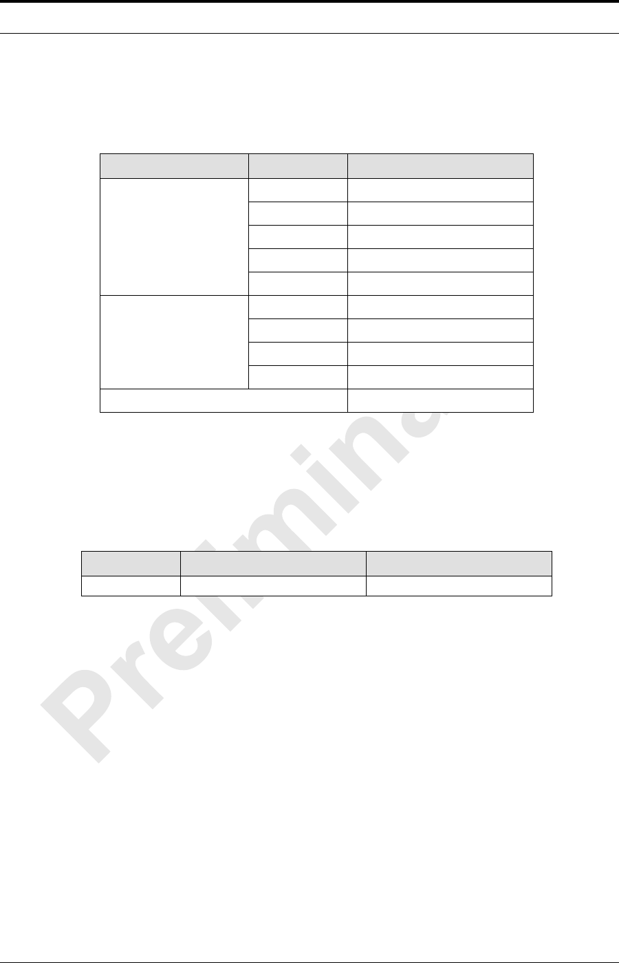
MC-Series Standard Capacity system Field Replaceable Unit
Parts List
Table 1.1 contains current parts list for the MCSC system that are Field Replaceable
units (FRU).
Refer to section 9.1.1 (Field Replaceable Unit (FRU) Policy) or replacing any of the
following equipment. For equipment not supplied by RadioFrame Networks, follow
standard policies and procedures for FRU replacement.
Warning
Use extreme caution when wearing a conductive wrist strap near sources of high
voltage

MC-Series ©2008 RadioFrame Networks, Inc. 1-5
Proprietary and Confidential Information
MC-Series Standard Capacity system998-1019-01 Rev X1
Table 1.1 FRU Table
The MCSC system contains both RadioFrame Networks and non-RadioFrame
Networks equipment enclosed in a single 30” H x 25” W x 30” D Air Conditioned
equipment cabinet. The MCSC system is a three-sector configuration that supplies
twelve RadioBlade transceivers per sector.
The MCSC system is shipped ready to install and configure. The customer provides
the following:
• All non-RadioFrame Networks hardware. Refer to Section 1.8
• T1 connectivity
• Datafill (network provisioning)
• Antenna system
• GPS (as required by iSCIII)
• Electrical supply and the necessary permitting
RadioFrame
Networks PN Description
176-0610-XX Power Distribution Unit (PDU)
176-1040-XX Airlink/BTS Interface Chassis (ABIC)
176-7090-XX MC-Series system Rx Filter
176-1076-XX MC-Series system RF Shelf
176-1030-XX Diversity RadioBlade Transceiver Shelf (DRBS) (3)
176-1090-XX 800E Tx Filter
176-1223-01 Outdoor Pole Mount Enclosure
176-1219-XX Fan Tray (w/fans) for a 4u Chassis
176-0011-XX Fans for DRBS and RF Shelf
176-7555-XX Base Processing Card (BPC) w/(2) SPAM-HC
176-7540-XX MC Common RadioFrame Interface Card (CRIC)
176-7562-XX Ethernet Rear Transition Module (ERTM)
176-0820-CC Coaxial RMII Transceiver Card (CRTC)
176-7502-XX 4U Chassis
176-0860-XX MCRB iDEN FRU
MC-Series Standard Capacity system 998-1019-01 Rev X1
1-6 ©2008 RadioFrame Networks, Inc. MC-Series
Proprietary and Confidential Information
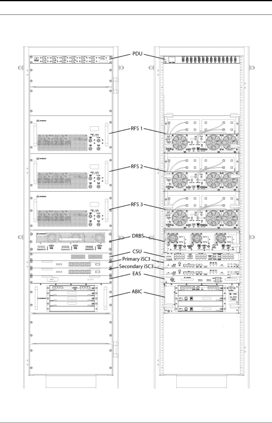
Figure 1.1 The MC-Series Standard Capacity system (as shipped)

MC-Series ©2008 RadioFrame Networks, Inc. 1-7
Proprietary and Confidential Information
MC-Series Standard Capacity system998-1019-01 Rev X1
1.5 MC-Series Standard Capacity system Configuration
The MCSC system is configured with three sectors. Configurations are summarized
in Table 1.2.
Table 1.2 Sectorization and Maximum BR Allocation
The MCSC system includes the following RadioFrame Networks hardware:
• Airlink BTS Interface Chassis (ABIC) is the interface to the iSCIII and routes
Ethernet traffic for up to three sectors. It also performs the digital receive and
transmit function for each RadioBlade® transceiver and provides the common
timing source for the DRBS.
• The Diversity RadioBlade Shelf (DRBS) supports up to eight RadioBlade
transceivers.
• iDEN RadioBlade transceivers insert into slots in the DRBS; each multi-
channel RadioBlade (MCRB) transceiver corresponds to up to six iDEN
carriers in the 800E MHz band.
• Three RF Shelfs provide Rx-Tx amplification, filtering, and distribution between
the DRBS and external equipment.
• Power Distribution Unit (PDU) distributes DC power and provides overcurrent
protection to each component in the MCSC system cabinet.
The MCSC system requires the installation of the following non-RadioFrame
Networks hardware:
• Two integrated Site Controllers (iSCIII).
• Environmental Alarm System (EAS) provides additional external alarming as
required.
• Channel Service Unit (CSU) single-rack unit RU), high multi-purpose cross-
connect, with the ability to aggregate multiple types of traffic onto a single T1/
E1 for backhaul to the MSO.
• DC power source
Configuration
Max RF Carrier per Sector
One
Sector Two
Sector Three
Sector
Sector One 12 NA NA
Sector Two 12 12 NA
Sector Three 12 12 12
MC-Series Standard Capacity system 998-1019-01 Rev X1
1-8 ©2008 RadioFrame Networks, Inc. MC-Series
Proprietary and Confidential Information
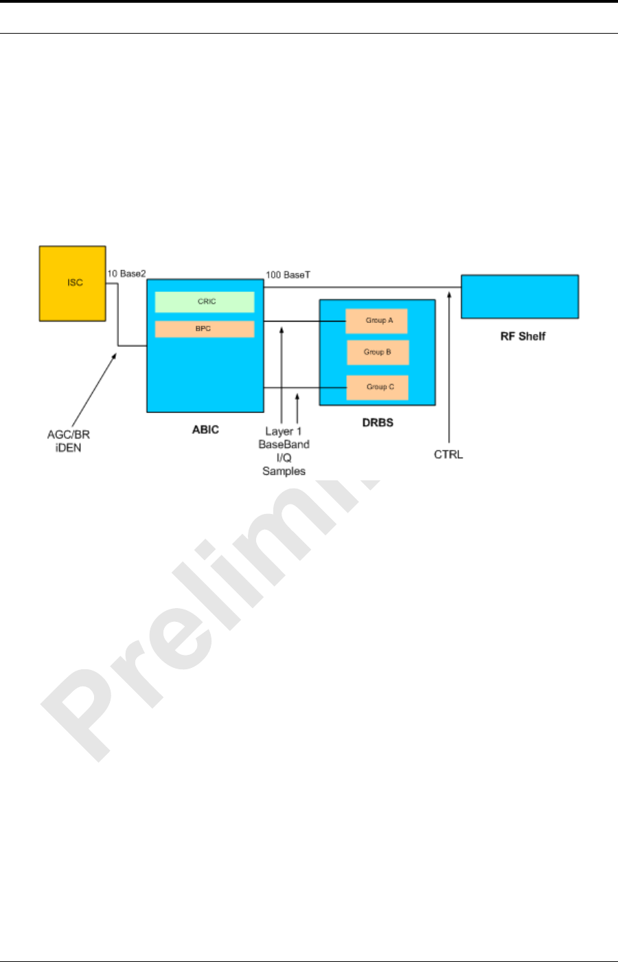
1.6 RadioFrame Networks Hardware
RadioFrame Networks hardware receives layer-3 control messages (control, voice,
packet data, SNMP, etc.) from the iSCIII and converts them into layer 2 PDUs
(Protocol Data Units) that are sent every 15 ms (received every 7.5 ms). Then the
ABIC converts the layer-2 PDUs into raw layer-1 Baseband I/Q samples that are
sent/received every 7.5 ms.
Figure 1.2 Default MCSC system Functional Diagram
1.6.1 Airlink BTS Interface Chassis (ABIC)
The ABIC interfaces to the iSCIII and provides all Base Radio (BR) management
functionality, including timing, converts iSCIII layer 3 messaging to layer 2
packets, converts 1PPS 5 MHz clock to packet-delivered timing, and provides
layer-1 and layer-2 processing of call data, including routing of packet data to
RadioBlade transceivers in DRBS, as well as timing to the DRBS. Within the ABIC
chassis are three assemblies (see the following illustrations):
• Common RadioFrame Interface Card (CRIC)
• BTS Processing Cards
• Ethernet Rear Transition Module (ERTM)
• Coax-to-RMII Transceiver Card (CRTC) deployed in rear slot 3
MC-Series ©2008 RadioFrame Networks, Inc. 1-9
Proprietary and Confidential Information
MC-Series Standard Capacity system998-1019-01 Rev X1
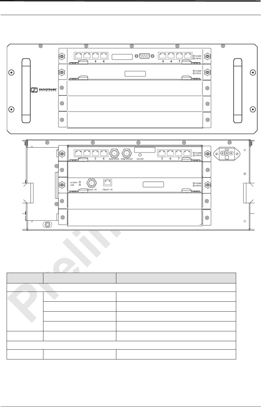
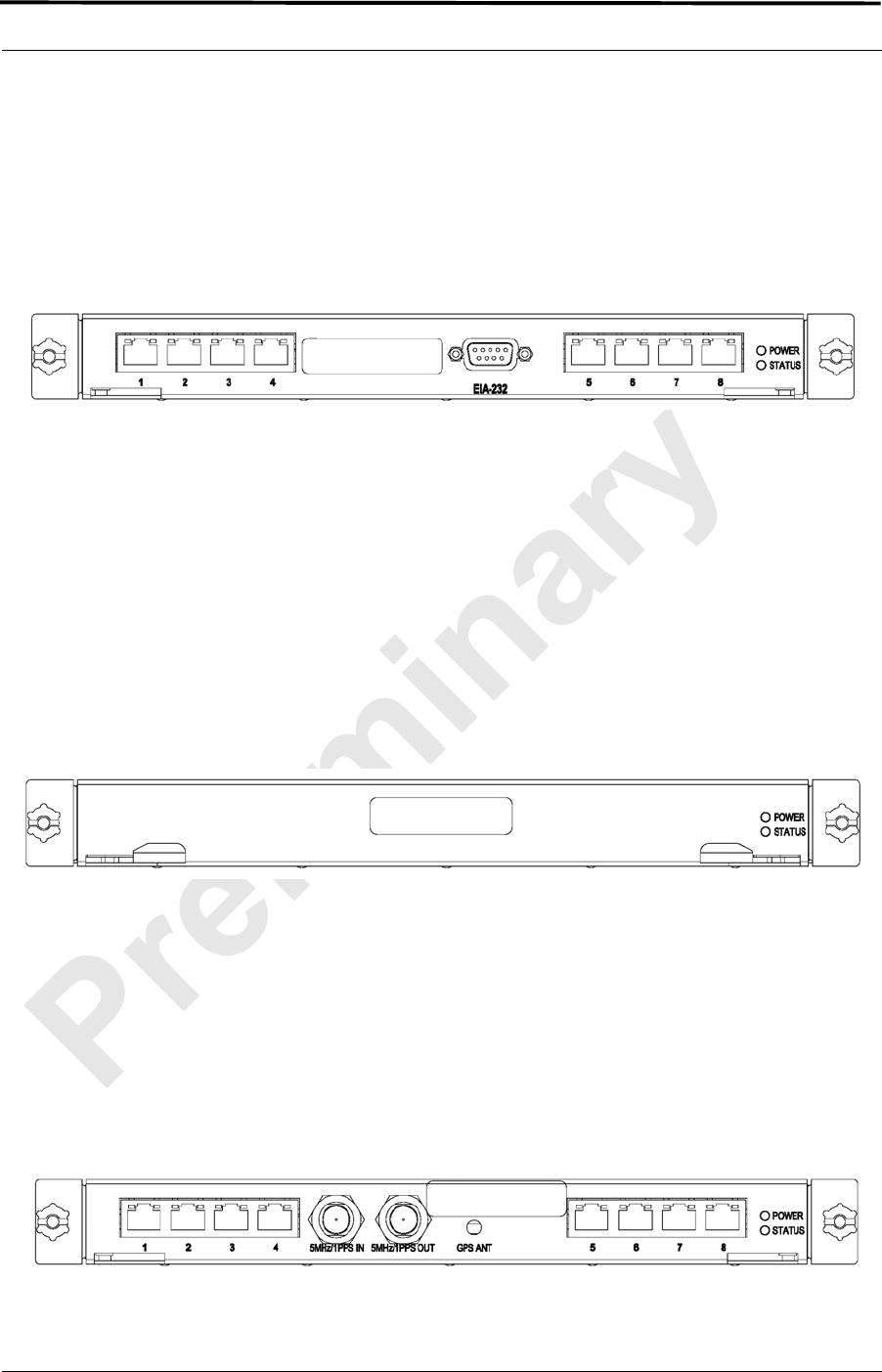
Figure 1.3 ABIC Front and Rear View
A. ABIC Ports
Table 1.3 Ports in the ABIC
Card Port Description
Front
ABIC CRIC Ports 1-6 (RJ-45) not currently used
Port 7 (RJ-45) technician local Ethernet access
Port 8 (RJ-45) technician remote Ethernet access
EIA-232 9-pin serial port serial access
BPC N/A N/A
Back
Port 1 (RJ-45) CRTC Port 10BaseT
MC-Series Standard Capacity system 998-1019-01 Rev X1
1-10 ©2008 RadioFrame Networks, Inc. MC-Series
Proprietary and Confidential Information
B. ABIC Indicators
Each card installed in the ABIC has a Power LED and a Status LED that
indicates timing synchronization.
Note: The CRIC Status LED represents PLL status.
The system will not go active unless this LED is
green.
Each RJ-45 port has an Ethernet link LED that indicates connectivity and an
Ethernet activity LED that indicates Ethernet traffic (ABIC RJ-45 Port
Indicators10).
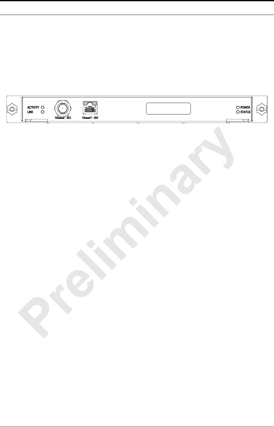
Figure 1.4 ABIC RJ-45 Port Indicators
1.6.2 CRIC
The ABIC Common RadioFrame Interface Card (CRIC) is located in the top front
slot of the ABIC. The ABIC CRIC provides the Ethernet switch fabric to route
packets to/from the ABIC and hosts a microprocessor that serves as the primary
controller of BPCs for system-management purposes. The ABIC CRIC has a
ERTM Port 2 (RJ-45) CRTC Port 10BaseT
Port 3 (RJ-45) RF Shelf 1 10/100 Port 1
Port 4 (RJ-45) RF Shelf 2 10/100 Port 1
Port 5 (RJ-45) RF Shelf 3 10/100 Port 1
Port 6 (RJ-45) Group A
Port 7 (RJ-45) Group B
Port 8 (RJ-45) Group C
5 MHz/1PPS IN iSCIII 5-MHz/1PPS port
5 MHz/1PPS OUT not currently used (no terminator required)
GPS ANT not currently used
CRTC 10Base2 – iSCIII iSCIII 10Base2 port
10BaseT – iSCIII ABIC ERTM port 1
link activit
y
MC-Series ©2008 RadioFrame Networks, Inc. 1-11
Proprietary and Confidential Information
MC-Series Standard Capacity system998-1019-01 Rev X1
serial port for local serial access, and eight 10/100BaseT Ethernet ports.
Currently, ports 1 through 6 are not used; port 7 is used for local technician access
while port 8 is available for remote Ethernet access.
Figure 1.5 CRIC Ports and Indicators
1.6.3 BPC
The BTS Processing Card (BPC) is located in ABIC front-slot position 2. The BPC
hosts a microprocessor to perform iDEN voice management and is responsible for
layer-2 call processing.
Note: If adding the expansion sectors (not covered in
this document), a BPC must be added for each
sector.
Figure 1.6 BPC indicators
1.6.4 ERTM
The Ethernet Rear Transition Module (ERTM) is located in the top rear slot of the
ABIC. The ERTM interfaces to the CRIC via eight RMII ports in the chassis
midplane. The ERTM provides Ethernet connectivity between the ABIC and the
CRTC.
Figure 1.7 ERTM Ports and Indicators
MC-Series Standard Capacity system 998-1019-01 Rev X1
1-12 ©2008 RadioFrame Networks, Inc. MC-Series
Proprietary and Confidential Information
1.6.5 CRTC
The Coax-to-RMII Transceiver Cards (CRTCs) is located in the bottom rear slot of
the ABIC. The CRTC provides conversion of the 10Base2 connection at the iSCIII
to a 10BaseT connection in the ABIC.
Figure 1.8 CRTC Ports and Indicators
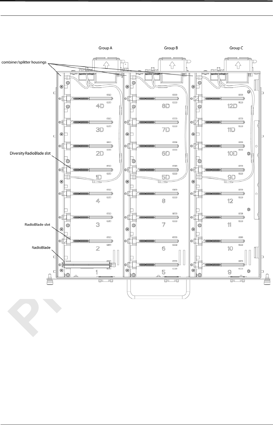
1.6.6 Diversity RadioBlade Shelf (DRBS)
The RadioBlade Shelf (DRBS) houses the Multi-Channel RadioBlade
transceivers, the RadioBlade transceiver “backplane” and RF combiner and
splitter assemblies. The whole assembly is housed in a pullout shelf to facilitate
field replacement of the RadioBlade transceivers.
The DRBS is divided logically into sets of eight slots. Each set of slots is referred
to as a group from left to right when facing the front of the unit. The groups share
redundant DC-DC converters. The slot connectors on the DRBS provide the
control and data interface to each RadioBlade transceiver. Each group interfaces
with the ABIC via a separate 100BaseT Ethernet connection. In addition, a serial
console port and status LEDs for each group are routed to the front panel of the
DRBS.
RF combining is also accomplished on a per group basis. Integrated into the
DRBS are 1:4 power splitters for the Rx path and 4:1 power combiners for the Tx
path.
MC-Series ©2008 RadioFrame Networks, Inc. 1-13
Proprietary and Confidential Information
MC-Series Standard Capacity system998-1019-01 Rev X1
Figure 1.9 DRBS Interior, Top Down View
MC-Series Standard Capacity system 998-1019-01 Rev X1
1-14 ©2008 RadioFrame Networks, Inc. MC-Series
Proprietary and Confidential Information
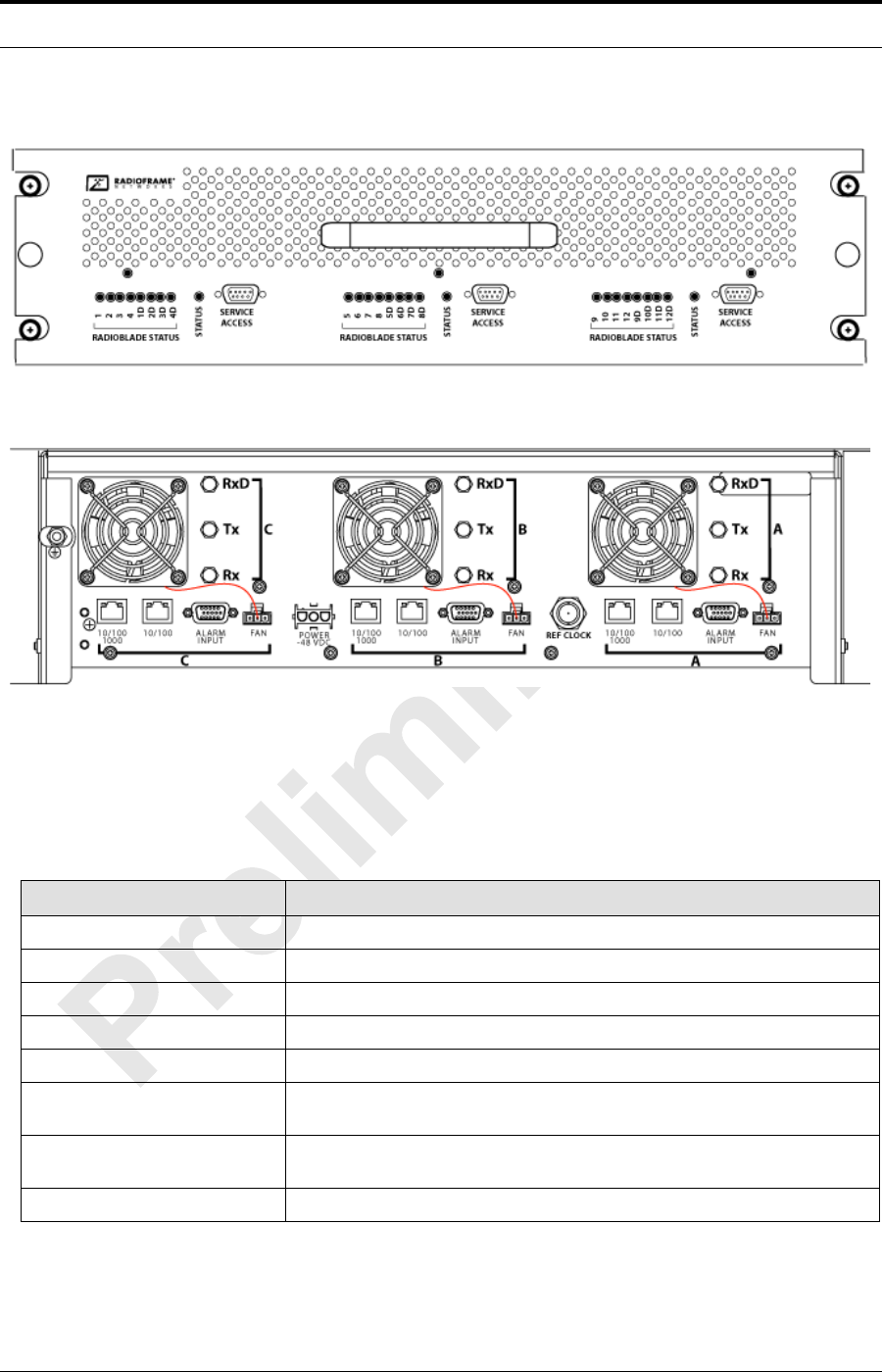
Figure 1.10 DRBS Front and rear View
A. DRBS Ports
Table 1.4 DRBS Ports
Ports Description
Front Ports
Service Access (A, B, C) technician local serial access
Rear Ports
Tx / Rx (A, B, C) Input and output for RF Shelf (wiring depends on system configuration)
Fan (A, B, C) Power connector
Alarm Input (A, B, C) ALARM serial port on the back of RF Shelf; THESE PORTS ARE NOT
USED WITH MCSC system
10/100 RadioFrame Networks
(A, B, C) 100Base-T Ethernet from ABIC ERTM Ethernet ports 1, 2 and 3
(respectively)
Ref Clock not currently used
MC-Series ©2008 RadioFrame Networks, Inc. 1-15
Proprietary and Confidential Information
MC-Series Standard Capacity system998-1019-01 Rev X1
B. DRBS Indicators
The front of the DRBS has the following LED indicators:
•STATUS indicator for each group
•RADIOBLADE TRANSCEIVER STATUS indicators, one for each
RadioBlade transceiver slot in the DRBS. LEDs are arranged by group (8
per group) and are numbered consecutively from left to right:
• A: 1-4/1D-4D
• B: 5-8/5D-8D
• C: 9-12/9D-12D
Each RJ-45 port (rear only) has an Ethernet link LED that indicates
connectivity and an Ethernet activity LED that indicates Ethernet traffic.
Table 1.5 DRBS Indicator LEDs
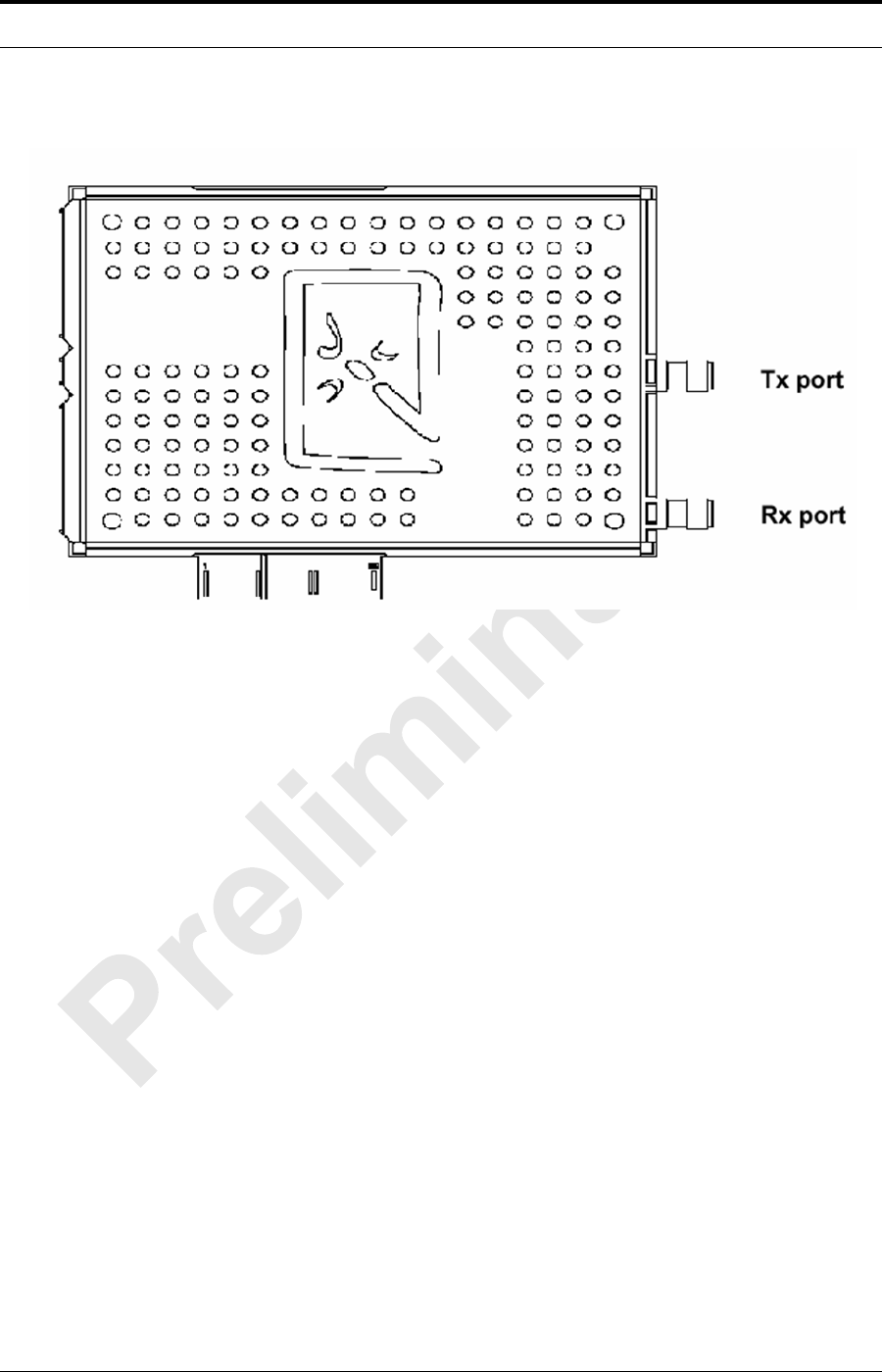
1.6.7 Multi-Channel RadioBlade (MCRB) Transceivers
Each multi-channel RadioBlade (MCRB) transceiver corresponds to up to six
iDEN carriers in the 800E MHz band.Refer to Figure 1.11.
This edge connector provides all data interfaces and clock inputs to the
RadioBlade transceiver. The RF interface employs two SMA connectors, one for
transmit and the other for receive.
LED Indication
STATUS Indicates timing synchronization for group
RADIOBLADE TRANSCEIVER STATUS Indicates status of RadioBlade: green = operational;
red = alarm condition; not lit = RadioBlade not present
MC-Series Standard Capacity system 998-1019-01 Rev X1
1-16 ©2008 RadioFrame Networks, Inc. MC-Series
Proprietary and Confidential Information
Figure 1.11 Multi-Channel RadioBlade Transceiver
The MCRB duplicates the RF functions of up to 6 simultaneously operational
iDEN radio transceivers, supporting six corresponding Transmit (Tx) – Receive
(Rx) channel pairs with full-duplex operation. The MCRB operates in the 800E
Mhz band as configured by system software.
MC-Series ©2008 RadioFrame Networks, Inc. 1-17
Proprietary and Confidential Information
MC-Series Standard Capacity system998-1019-01 Rev X1
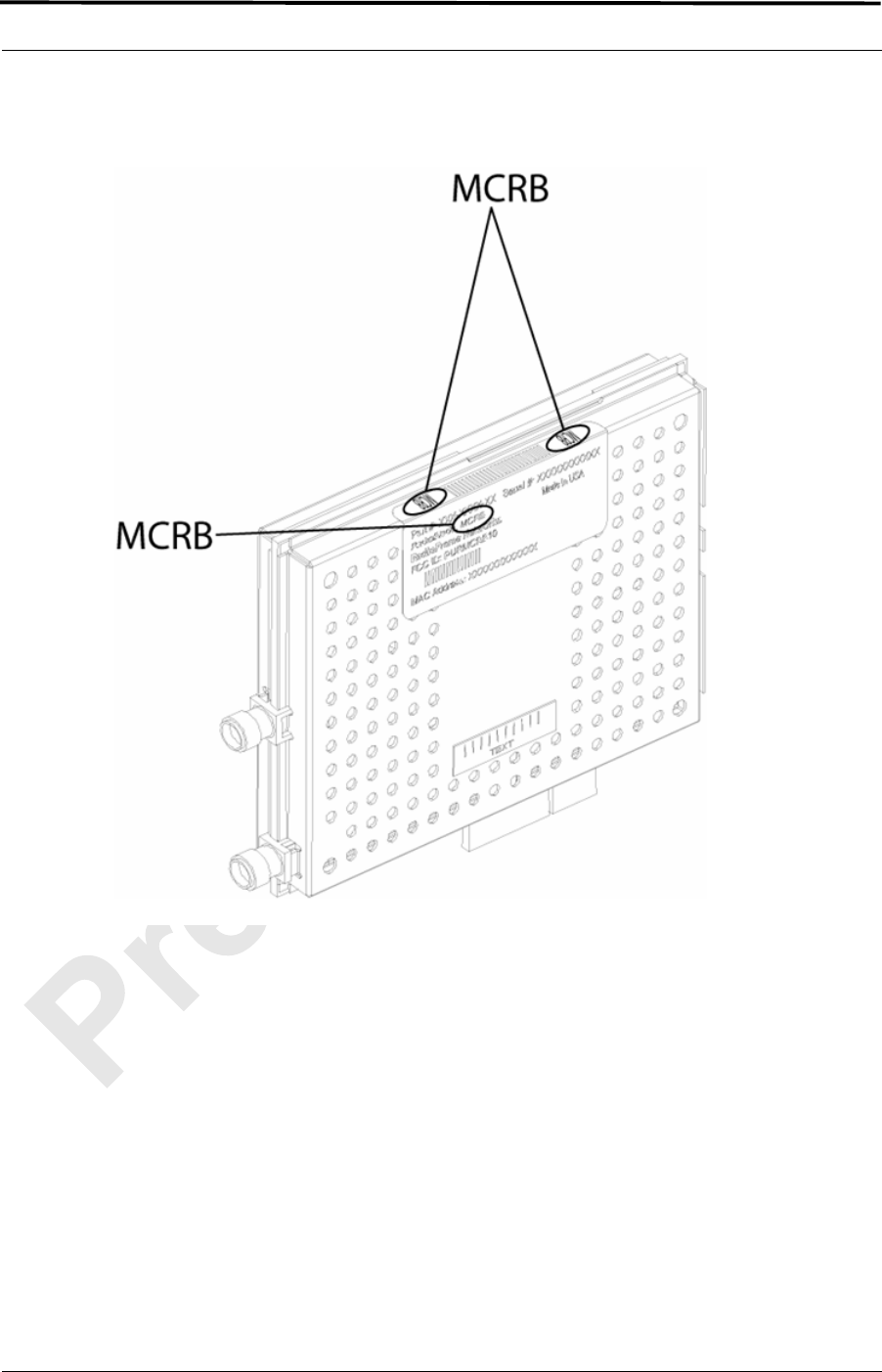
Figure 1.12 MCRB Label Position
A. Combined RadioBlade Transceivers in an DRBS
The MCRB allows up to 6 BRs to be assigned to a single physical RadioBlade
transceiver with a requirement applied that all carriers need to be within a 1.25
MHz band. Because of this requirement, all frequencies need to be known prior
to the programming of the MCRB. To accommodate this, all BRs set up in the
iDEN configuration page will register with the network to get assigned
frequencies. Once the frequencies are known, and the available HW resources
are known, the carriers are assigned to the MCRBs by the following rules:
1. Control channels are assigned first.

MC-Series Standard Capacity system 998-1019-01 Rev X1
1-18 ©2008 RadioFrame Networks, Inc. MC-Series
Proprietary and Confidential Information
2. The largest group of carriers which fall within the 1.25 MHz band is
assigned to the MCRB if one is available. (Note: This process repeats
until there are no remaining unassigned MCRBs.)
3. Any carriers that remain unassigned, an alarm is sent to the OMC.
4. If any MCRBs are unassigned, they become standby blades.
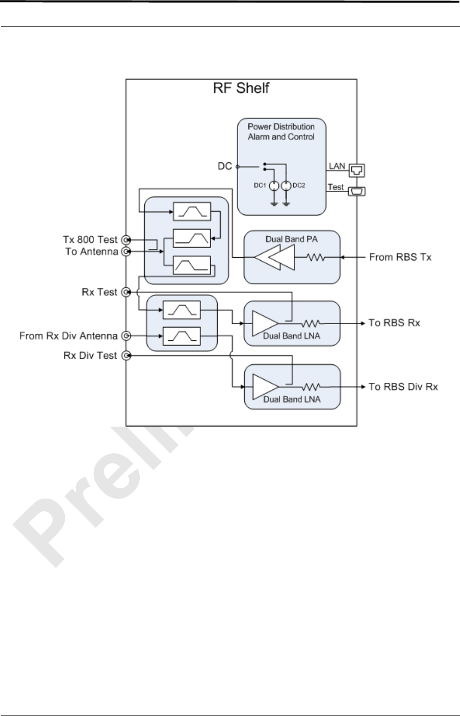
1.6.8 MC-Series Standard Capacity RF Shelf
The MCSC system provides one RF shelf per sector. The RF shelf contains
amplifiers, filters, combiners, redundant DC-DC converters and fans to provide
cooling to the power amplifiers (PAs).
The transmit chain includes a software-controlled variable attenuator for adjusting
the Tx power output at the rear of the enclosure, a multi-channel linear power
amplifier (PA), a band pass filter and a sampling port. The Tx sampling port
provides approximately Top of Rack (TOR) minus 20 dB output power. The Tx
power output at the rear of the enclosure can be varied by changing the datafill.
The PA is sized to allow sufficient linearity and gain such that a minimum of+36
dBm per carrier for up to 3 carriers, +33 dBm per carrier for up to 6 carriers and
+30 dBm for 12 carriers can be achieved at the rear of the enclosure. The
sampling port signal is brought out to the front of the RF shelf to provide
monitoring and testing of the transmit path.
The receive path contains a band pass filter, low noise amplifier (LNA) and a
sampling port. As with the Tx sampling port, the Rx sampling port is brought out to
the front panel of the RF shelf. The Rx sampling port provides approximately Top
of Rack (TOR) minus 20 dB output power.
Input/Output is directed through the following ports:
•Tx/Rx
•Rx Div
MC-Series ©2008 RadioFrame Networks, Inc. 1-19
Proprietary and Confidential Information
MC-Series Standard Capacity system998-1019-01 Rev X1
Figure 1.13 MC-Series Standard Capacity system RF Shelf Functional Diagram
MC-Series Standard Capacity system 998-1019-01 Rev X1
1-20 ©2008 RadioFrame Networks, Inc. MC-Series
Proprietary and Confidential Information
Figure 1.14 MC-Series Standard Capacity system RF Shelf Front and Rear View
1.6.9 Power Distribution Unit
The Power Distribution Unit (PDU) receives DC input and supplies power via
dedicated circuit breakers to each component in the MCSC system. Each of the
breakers has a three-position switch: ON, OFF or TRIPPED. The single alarm
output connected to each breaker is normally closed, and goes open when a
breaker is tripped.

MC-Series ©2008 RadioFrame Networks, Inc. 1-21
Proprietary and Confidential Information
MC-Series Standard Capacity system998-1019-01 Rev X1
Table 1.6 PDU Circuit Breaker Overview
Figure 1.15 PDU Front and Rear View
1.6.10 System Manager Software
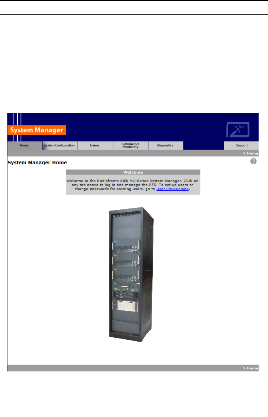
The MCSC system is managed and configured via RadioFrame Networks System
Manager, a Web-based graphical management system, which is accessible via
any IP-based connection. System Manager provides Operations personnel with
remote access and control, including configuration, alarm monitoring, triage/
troubleshooting and system statistical reporting. All RadioFrame Networks MCSC
systems include System Manager as standard equipment. Core System Manager
functions include:
• Software download (both locally and remotely)
• Status & Configuration screens
• Local & remote software upgrade—concurrent distribution of software
upgrades across all network elements (via script)
• Configuration management
• System parameters display
• System performance statistics
• Diagnostics and troubleshooting
• Voice loopback
Breaker
(Amps) Quantity
15 3
10 4
6 2
3 4
MC-Series Standard Capacity system 998-1019-01 Rev X1
1-22 ©2008 RadioFrame Networks, Inc. MC-Series
Proprietary and Confidential Information
• Administrative Lock/Unlock of Carriers/BRs
• Real time Alarm Manager with X.733 Alarming
• Call Statistics and Uptime
• RF Performance Metrics (e.g., Uplink SQE, Noise Floor, etc.)
• Test and Maintenance (e.g., automated BER testing)
Figure 1.16 System Manager Main Page

MC-Series ©2008 RadioFrame Networks, Inc. 1-23
Proprietary and Confidential Information
MC-Series Standard Capacity system998-1019-01 Rev X1
1.7 MC-Series Standard Capacity system cabinet
The MCSC system cabinet is a short 19” equipment cabinet with lockable front and
rear doors, 4,000 BTU air conditioning unit, allowing access to the system without
opening the doors. The cabinet is rated for operating in an environment of -32° to
+52° C ambient. External RF connectors are flush with the rear of the enclosure in a
recessed bulkhead. For more information, refer to the cabinet manufacturer’s
documentation shipped with the MCSC system.
1.7.1 Air Conditioning
The MCSC system comes with a 4,000 BTU air conditioning unit installed on the
front door. Refer to Appendix C , Section C.1.11 (Air Conditioning Cabling) for
wiring information.
1.8 Non-RadioFrame Networks Hardware (must be installed)
Non-RadioFrame Networks hardware for the MCSC system must be procured and
then installed in order for the MCSC system to be complete.
1.8.1 integrated Site Controller (iSCIII (must be installed))
The MCSC system uses a integrated Site Controller or iSCIII, which is connected
to the macro network through a Channel Service Unit (CSU). The connection
between the iSCIII and the MCSC system is via a coaxial interfaces. The first is a
10Base2 Ethernet connection to provide data communications. This connection is
made directly to the MCSC system and does not require an external media
converter.
For more information about the iSCIII, refer to the Motorola document Gen 3 Site
Controller System Manual, 68P80801E30-O.
1.8.2 Environmental Alarm System (EAS (must be installed))
The Environmental Alarm System (EAS) provides a central location for site alarm
signal processing. The EAS monitors site environmental conditions, including AC
power, smoke alarms, intrusion alarms, antenna tower lights, etc.
Each of the site alarm contacts are normally closed and connected to the EAS
through a 50-pin Champ cable that connects to a punch block. All alarm contact
pairs must be dry (isolated from ground). Most alarm connections are inputs.
Outputs provide a dry relay closure rated at 0.5 A, 30 Vrms or 60 VDC, 10 VA
max.
Plan to implement EAS alarm blocks, wiring and sensors as required depending
on the installation:
• Plan on providing standard facility environmental sensors, wiring, and
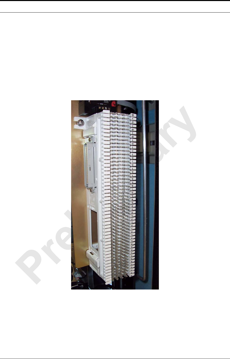
connections. The alarm blocks can be installed inside the enclosure, which
contains a 66-connection punch down block (Figure 1.17).
MC-Series Standard Capacity system 998-1019-01 Rev X1
1-24 ©2008 RadioFrame Networks, Inc. MC-Series
Proprietary and Confidential Information
• Plan to provide conduit or other wire routing from a door sensor, HVAC units
(if separate HVAC units are installed for the installation), and AC power
failure / surge arrestor failure sensors.
For more information about the EAS, refer to the Motorola document Gen 3 Site
Controller System Manual, 68P80801E30-O.
For more information regarding the Alarm wiring, refer to Appendix C , Section
C.1.10 (Alarm Cabling).
Figure 1.17 Punch Block Location within the MCSC system cabinet
1.8.3 Channel Service Unit (CSU--(must be installed))
The Channel Service Unit (CSU) provides the T1/E1 connection between the
iSCIII and the telephone company that provides the T1/E1 line. The CSU provides
surge protection to the T1/E1 line and loop-back testing for the telephone
company.

MC-Series ©2008 RadioFrame Networks, Inc. 1-25
Proprietary and Confidential Information
MC-Series Standard Capacity system998-1019-01 Rev X1
For more information about the CSU, refer to the manufacturer's documentation.
1.8.4 GPS Antenna System (must be installed)
The Global Positioning System (GPS) antenna provides GPS signals to the iSCIII,
which constructs the timing reference for the MCSC system hardware. One GPS
antenna with a dedicated 50 coax cable is required for each iSCIII.
1.8.5 Powerplant (must be installed)
The MCSC system cabinet is powered by a nominal –48 VDC powerplant
supplied by the customer. The powerplant will need to be installed in a separate
cabinet. The cabinet is shipped with a Power Distribution Unit (PDU) and the PDU
contains circuit breakers that provide overcurrent protection for MC-Series loads.
Note: The Air Conditioning unit mounted on the front
door will require an AC (230 V single phase)
power supply. Refer to Appendix C , Section
C.1.11 (Air Conditioning Cabling)

MC-Series Standard Capacity system 998-1019-01 Rev X1
1-26 ©2008 RadioFrame Networks, Inc. MC-Series
Proprietary and Confidential Information

MC-Series ©2008 RadioFrame Networks, Inc. 2-1
Proprietary and Confidential Information
MC-Series Standard Capacity system998-1019-01 Rev X1
Overview
This chapter describes the physical and environment specifications of the
MCSC system.
Contents
2.1 Physical Dimensions ............................................................................... 2-2
2.2 Weight...................................................................................................... 2-2
2.3 Power Specifications ............................................................................... 2-2
2.3.1 Power Requirements ........................................................................... 2-2
2.3.2 Power Consumption ............................................................................ 2-3
2.3.3 Grounding............................................................................................ 2-3
2.3.4 Heat Load ............................................................................................ 2-4
2.4 Performance Specifications ..................................................................... 2-4
2.4.1 Receiver Performance Summary......................................................... 2-5
2.4.2 Transmitter Performance Summary..................................................... 2-5
Operating Frequency Bands................................................................ 2-4
RF Performance Requirements........................................................... 2-4
2.4.3 Tx Power Out....................................................................................... 2-5
2.4.4 Spurious RF Emissions........................................................................ 2-6
2.5 Environmental Equipment Specifications ................................................ 2-6
2.6 Compliance.............................................................................................. 2-6
Chapter 2 Specifications

MC-Series Standard Capacity system 998-1019-01 Rev X1
2-2 ©2008 RadioFrame Networks, Inc. MC-Series
Proprietary and Confidential Information
2.1 Physical Dimensions
Table 2.1 Nominal Dimensions
2.2 Weight
Table 2.2 Weight
2.3 Power Specifications
2.3.1 Power Requirements
Supplier Component Equipment Dimensions
Width Depth Height
RadioFrame Networks Cabinet 23.5” 25.5” 79” N/A
ABIC 19” 13” 7” 4U
DRBS 19” 13” 5.25” 3U
RF Shelf (3x) 19” 13” 8.75” 15U
PDU 19” 10” 1.75” 1U
Non-RadioFrame Networks iSCIII (2x) 19” 9” 1.75” 2U
EAS 19” 15” 1.75” 1U
CSU 19” 12.5” 1.75” 1U
Supplier Component Weight
RadioFrame Networks Cabinet 459 lbs
ABIC 22 lbs
DRBS 60 lbs each (24 RadioBlades)
RF Shelf (3X) 168 lbs
PDU 10 lbs
Non-RadioFrame Networks iSCIII (2x) 16 lbs
EAS 6 lbs
CSU 10 lbs
MC-Series ©2008 RadioFrame Networks, Inc. 2-3
Proprietary and Confidential Information
MC-Series Standard Capacity system998-1019-01 Rev X1
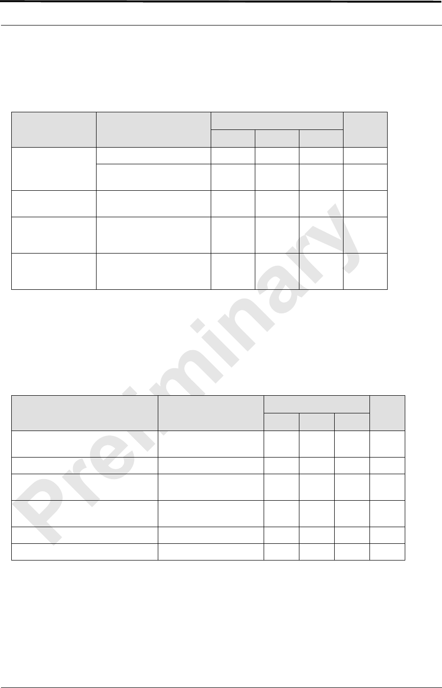
Table 2.3 Power Requirements
2.3.2 Power Consumption
Table 2.4 Power Consumption per Assembly (See Note)
Note: Panduit termination lugs are required for
installation. Wire size is AWG 6.
2.3.3 Grounding
Table 2.5 Grounding Resistance (See Note)
Note: Panduit termination lugs are required for
installation. Wire size is AWG 6.
Ground included with enclosure on main ground
block.
Supplier Component Power
RadioFrame Networks ABIC –48 VDC
DRBS –48 VDC
RF Shelf –48 VDC
PDU –48 VDC
Non-RadioFrame Networks iSCIII –48 VDC
EAS –48 VDC
CSU –48 VDC
Assembly Qty Power per
Assembly (W) Total Power
(W) Current
(A @ –48 VDC)
RF Shelf 1
DRBS (8 RadioBlade transceivers per) 3
ABIC 1
RadioFrame Networks Equiment Total 1483 30.9
iSCIII 2
EAS 1
CSU 1
Non-radioframe Networks Equipment Total 105.6 2.2
TOTAL 1588 33.1
Supplier Component Ground Resistance
(mOhms)
RadioFrame Networks Cabinet 0.6
MC-Series Standard Capacity system 998-1019-01 Rev X1
2-4 ©2008 RadioFrame Networks, Inc. MC-Series
Proprietary and Confidential Information
2.3.4 Heat Load
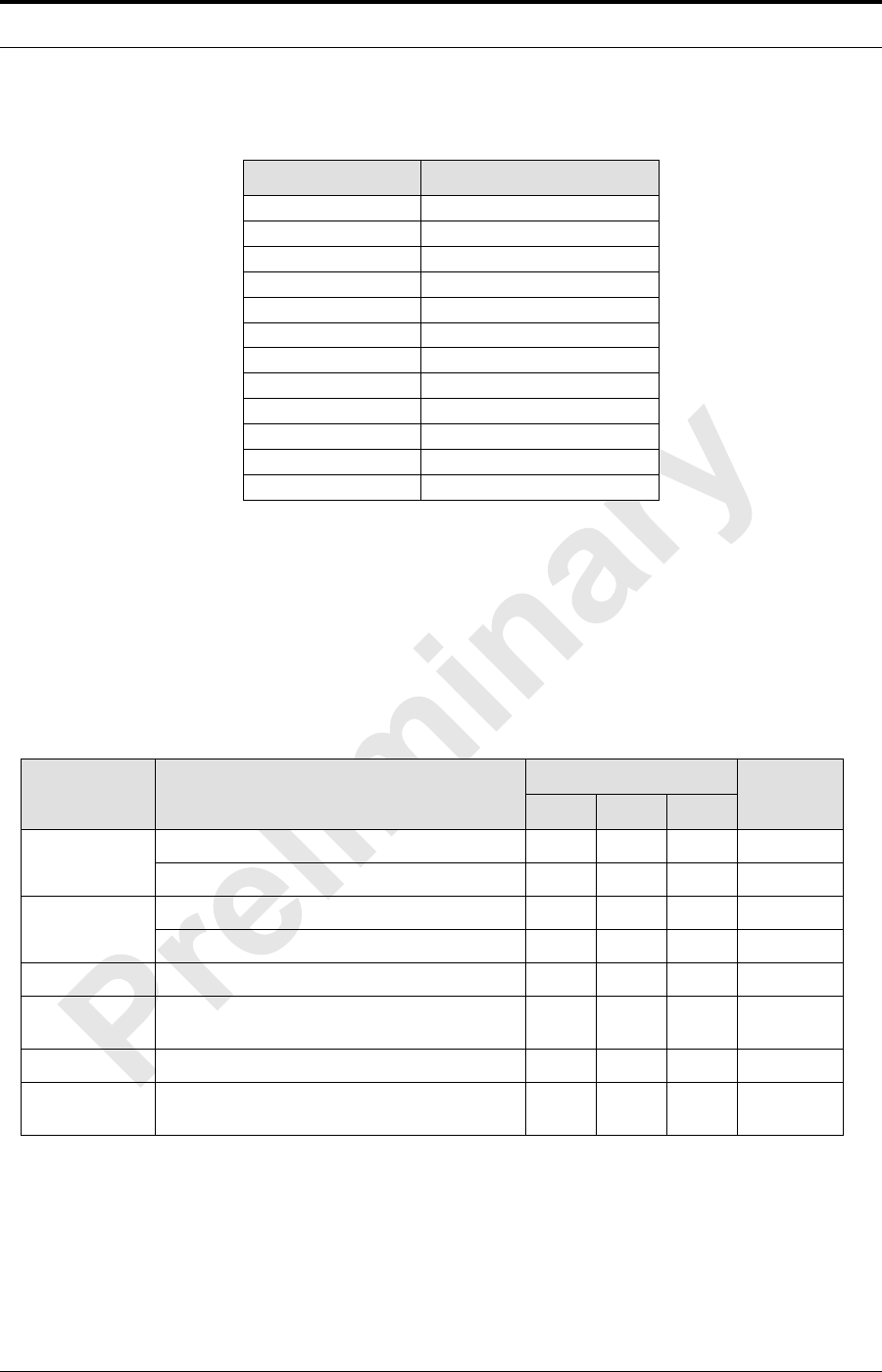
Table 2.6 Heat Load
2.4 Performance Specifications
Operating Frequency Bands
Table 2.7 Transmit and Receive Frequency Bands
RF Performance Requirements
The MCSC system will meet the emissions mask requirements per FCC Part 90,
section 90.691.
Supplier Component Heat Load (BTUs per Hour)
RadioFrame Networks
ABIC
DRBS
RF Shelf
PDU
Total 5064
Non-RadioFrame
Networks
iSCIII
EAS
CSU
Total 361
MCSC Unit totals 5425
Band Receive Frequency (MHz) Transmit Frequency (MHz)
800E 806 to 824 851 to 869
MC-Series ©2008 RadioFrame Networks, Inc. 2-5
Proprietary and Confidential Information
MC-Series Standard Capacity system998-1019-01 Rev X1
2.4.1 Receiver Performance Summary
Table 2.8 Receiver Performance Summary
Note: 1: Unless otherwise stated, all values are
referenced to the rear of the enclosure.
2.4.2 Transmitter Performance Summary
Table 2.9 Transmitter Performance Summary
Note: 1: Unless otherwise stated, all values are
referenced to the rear of the enclosure.
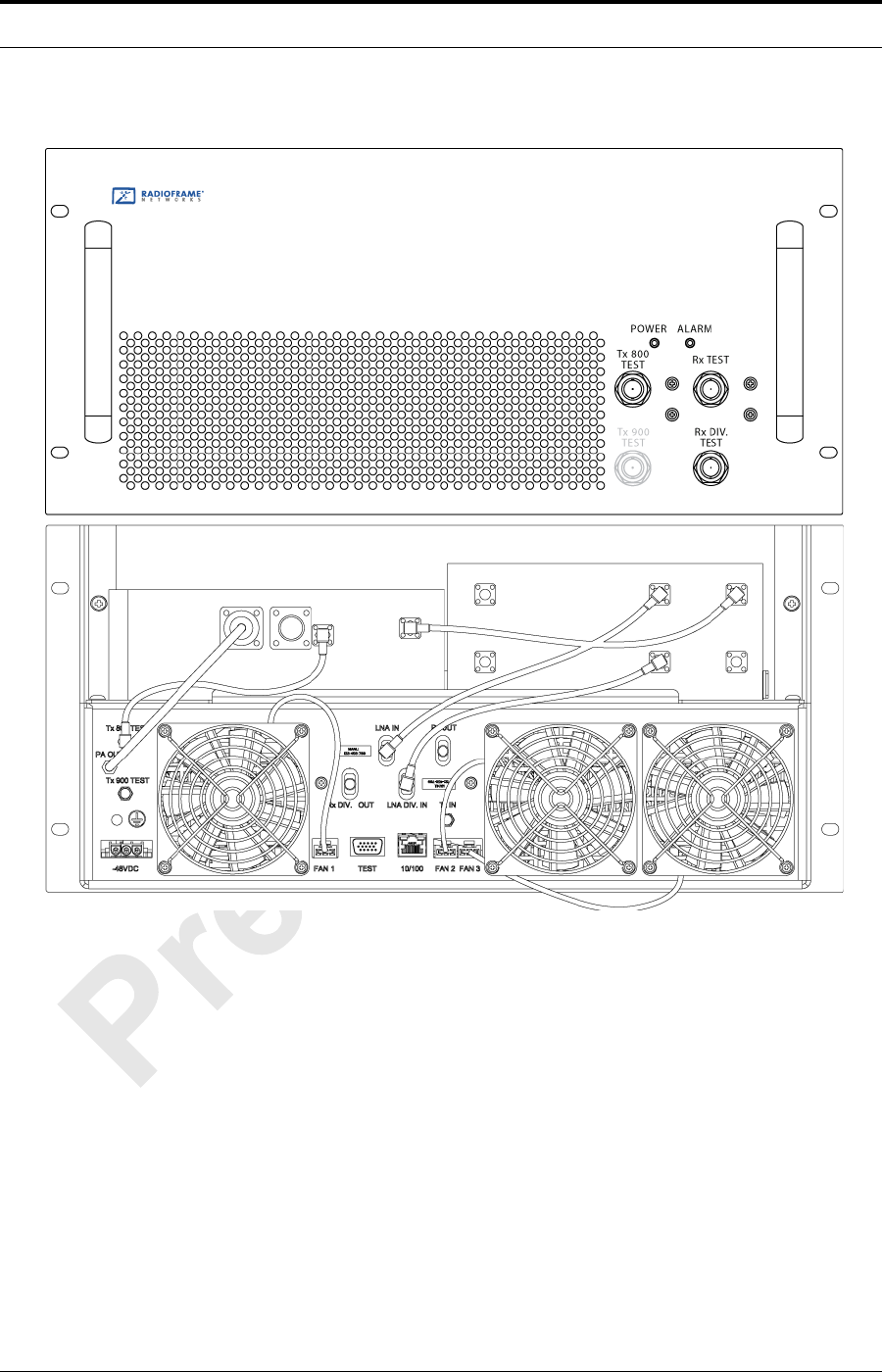
2.4.3 Tx Power Out
The transmit power out at the Top of Rack (TOR) is dependent on the OMC
datafill. Table 2.10 displays defaultTxPower vs. TOR output Power.
Parameter Condition (NOTE 1) Value Unit
Min Typ Max
Rx Input Level
2% BER –106 -- –40 dBm
Absolute Maximum where
no damage occurs -- -- +10 dBm
Residual BER Input signal level of –80
dBm -- -- 0.1 %
RSSI Input signed level -80dBm at
ambient operating
tempateure of 25°C -3 +3 dB
BER in the presence
of the adjacent
channel interferes
input signal level of 100
dBm and interfere signal
level f -60 dBM 2%
Parameter Condition (Note 1) Value Unit
Min Typ Max
Tx Output Power Level OMC Datafill: Default
TxPower = 9.8 +31 +33 +34 dBm
Tx Output Power Control Range +22 -- +36 dBm
Transmit port VSWR Referenced to a 50
impedance 10 -- dB
Downlink Signal Quality Estimator
(SQE) Average value -- 30 -- dB
Occupied bandwidth Per carrier -- -- 18.5 kHz
RF Frequency Tolerance (Tx) Average frequency -- -- ± 50 Hz
MC-Series Standard Capacity system 998-1019-01 Rev X1
2-6 ©2008 RadioFrame Networks, Inc. MC-Series
Proprietary and Confidential Information
Table 2.10 TOR Output Power
2.4.4 Spurious RF Emissions
The MC-Series iDEN Microcell system will meet the emissions mask
requirements per FCC 47 CFR part 90.
2.5 Environmental Equipment Specifications
Table 2.11 Environmental Specifications
2.6 Compliance
The MCSC system will meet the following safety and compliance specifications.
defaultTxPower TOR Tx Output (dBm)
8.4 +22
8.5 +23
8.6 +24
8.7 +25
8.8 +26
8.9 +27
9.0 +28
9.1 +29
9.2 +30
9.3 +31
9.4 +32
9.5 +33
Parameter Condition Value Unit
Min Typ Max
Ambient
Temperature
Normal operation –5 +40 °C
Storage –40 +70 °C
Humidity Normal operation relative, non-condensing 595%
Storage, non-condensing 595%
Altitude Relative to mean sea level. –60 1800 m
Seismic Level 4 earthquake; meets or exceeds GR-63-
Core 99.9 % pass
UL Pollution Degree 2 99.9 % pass
Transport
Vibration Meets or exceeds GR-63-Core compliant 99.9 % pass

MC-Series ©2008 RadioFrame Networks, Inc. 2-7
Proprietary and Confidential Information
MC-Series Standard Capacity system998-1019-01 Rev X1
Table 2.12 Agency Compliances
Standard Description
CISPR 22 International EMC compliance
EN60950 Compliance The Standard Capacity Main Cabinet Enclosure shall comply with EN60950.
FCC Compliance The Standard Capacity Main Cabinet Enclosure shall comply with FCC 47 CFR Part
15. The Standard Capacity Main Cabinet Tx shall comply with FCC Part 90.

MC-Series Standard Capacity system 998-1019-01 Rev X1
2-8 ©2008 RadioFrame Networks, Inc. MC-Series
Proprietary and Confidential Information

MC-Series ©2008 RadioFrame Networks, Inc. 3-1
Proprietary and Confidential Information
MC-Series Standard Capacity system998-1019-01 Rev X1
Overview
This section provides pre-installation information for the MC Series MCSC
system at the site.
Contents
3.1 Pre-Installation Requirements ................................................................. 3-3
3.2 Site Planning ........................................................................................... 3-3
3.2.1 Space Requirements ........................................................................... 3-3
3.2.2 Anchoring............................................................................................. 3-3
3.2.3 Seismic Zone Installation..................................................................... 3-4
3.2.4 Cooling of Equipment .......................................................................... 3-4
3.2.5 Power................................................................................................... 3-5
3.2.6 Grounding............................................................................................ 3-5
3.2.7 GPS Antennas..................................................................................... 3-5
3.2.8 T1 Service............................................................................................ 3-5
3.2.9 Alarm Blocks........................................................................................ 3-6
3.2.10 Environmental Alarm System (EAS).................................................... 3-6
3.3 Scheduling / Logistics.............................................................................. 3-6
3.4 iDEN Configuration.................................................................................. 3-7
3.4.1 Cabinet and Position Settings.............................................................. 3-7
3.4.2 BRs...................................................................................................... 3-7
3.4.3 Sectorization........................................................................................ 3-7
3.5 Site Inspection......................................................................................... 3-7
3.6 Receipt of Equipment .............................................................................. 3-8
RadioFrame Networks......................................................................... 3-8
Non-RadioFrame Networks ................................................................. 3-8
3.6.1 Equipment Inspection .......................................................................... 3-8
Chapter 3 Pre-Installation

MC-Series Standard Capacity system 998-1019-01 Rev X1
3-2 ©2008 RadioFrame Networks, Inc. MC-Series
Proprietary and Confidential Information
3.6.2 Equipment Inventory ............................................................................3-8

MC-Series ©2008 RadioFrame Networks, Inc. 3-3
Proprietary and Confidential Information
MC-Series Standard Capacity system998-1019-01 Rev X1
3.1 Pre-Installation Requirements
Prior to installation, prepare the site with all associated antennas, phone lines, and
other related site equipment.
3.2 Site Planning
For each of the ensuing site planning subsections, complete the following:
1. Identify work to be completed by technicians and outside contractors.
2. Create a list of materials to be used by technicians in completing the work.
3. Create statements of work (SOWs) for work to be completed by outside
contractors.
3.2.1 Space Requirements
Establish the specifications to meet National Fire Protection Associations (NFPA)
Code and American Society of Heating, Refrigerating and Air Conditioning
Engineers (ASHRAE) standards.
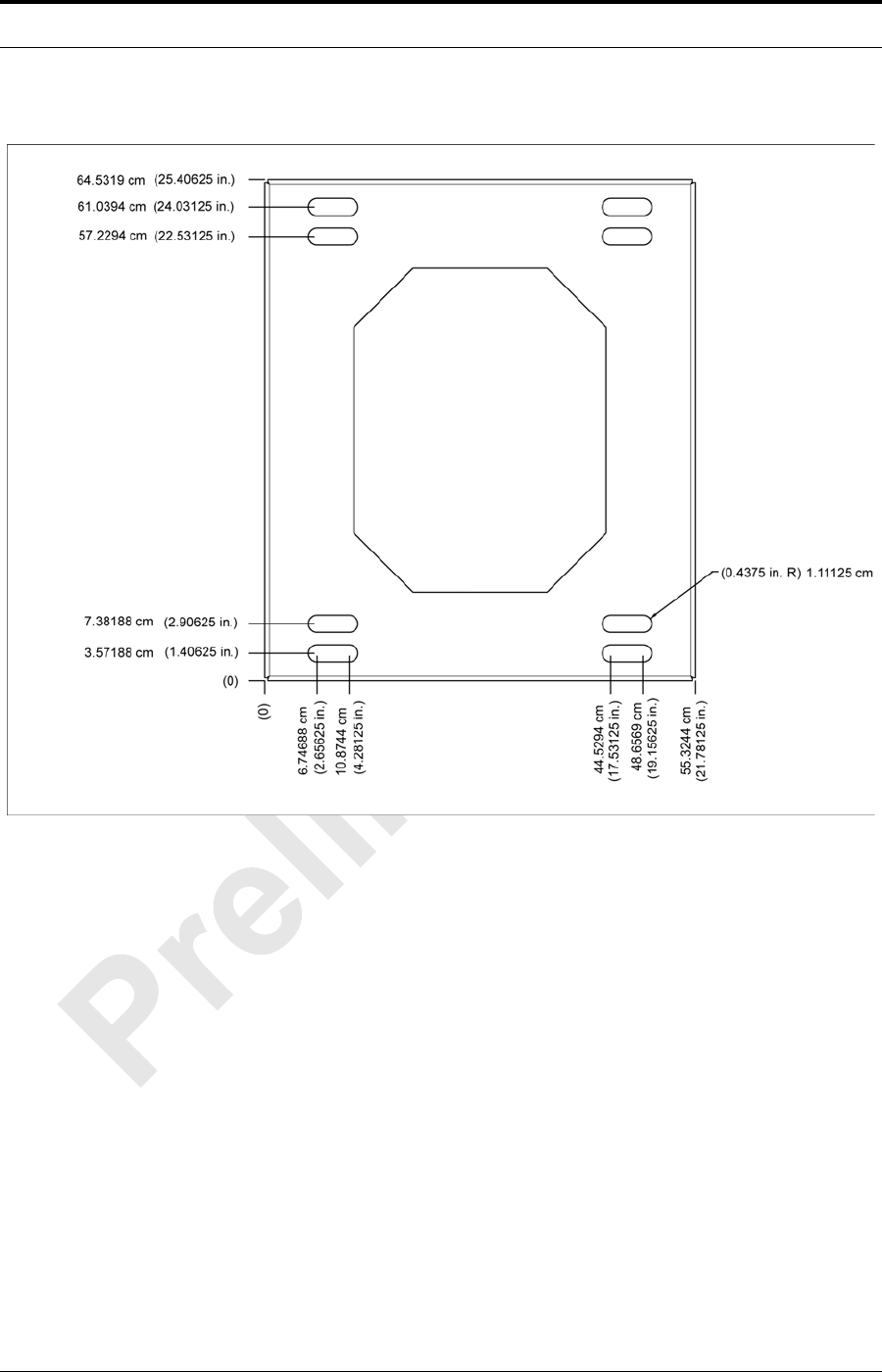
3.2.2 Anchoring
Bolting the MC-Series to the floor is required. The MC-Series should NEVER be
placed on casters or wheels of any kind.
Refer to FIGURE for the anchoring bolt template for the MC-Series electroRack
enclosures.
MC-Series Standard Capacity system 998-1019-01 Rev X1
3-4 ©2008 RadioFrame Networks, Inc. MC-Series
Proprietary and Confidential Information
Figure 3.1 MC-Series Anchor Bolt Template
3.2.3 Seismic Zone Installation
Seismic testing is currently underway to determine the Seismic Zone ratings for
the MCSC system.
However, the property owner is responsible for any damage to RadioFrame
Networks equipment due to building or cabinet structures not secured to withstand
vibrations.
Ensure that a certified architect specializing in earthquake-resistant installation
provides seismic designs and recommendations in areas where the potential loss
of the site may outweigh associated costs of earthquake-resistant design. PE
stamped drawings shall be provided before the installation proceeds.
3.2.4 Cooling of Equipment
The enclosure has a built-in Air Conditioning system producing 4,000 BTUs.

MC-Series ©2008 RadioFrame Networks, Inc. 3-5
Proprietary and Confidential Information
MC-Series Standard Capacity system998-1019-01 Rev X1
3.2.5 Power
Ensure that a DC power source is available that can supply full power
requirements for both the MCSC system cabinet and all ancillary equipment
(including a heater) for the installation. This power source may be a bulk DC
power source, or an external DC powerplant. Backup batteries may or may not be
required, depending on whether or not the powerplant is driven from an
Uninterruptible Power Supply (UPS). Refer to standards for DC power design.
Any installation of AC power conductors shall be done by a licensed, bonded and
insured electrician. Follow standard design practices for AC and DC power circuits
including any required AC surge protection. Identify any contract labor and
materials required.
Refer to Chapter 2 (Specifications) for DC power requirements. Plan to use
termination lugs. Type is Panduit 2-hole, P/N LCD6-14A, or equivalent. Required
crimp tool is CT-1700.
3.2.6 Grounding
The MCSC system cabinet must be grounded to either a defined equipment
grounding system in a facility or to the building grounding electrode in a customer
facility. Plan to install a grounding system for the MCSC system cabinet and
ancillary hardware. Refer to Chapter 7 and Appendix C of Motorola R56, as
modified , for grounding standards. The Master Ground Bar (MGB) will be
installed on the wall on the telco board. Plan to use termination lugs. Type is
Panduit 2-hole, P/N LCD6-14A, or equivalent. Required crimp tool is CT-1700.
3.2.7 GPS Antennas
Refer to the Motorola Gen 3 Site Controller System Manual, 68P80801E30-O
document and standards for GPS antenna design and installation. Per the NEC
(1) any cabling run through an air plenum shall be plenum-rated, and (2) cabling is
not to be laid on or suspended from any ceiling grid or attached to the grid
supports. Identify any contract labor and materials required.
3.2.8 T1 Service
Install T1 cabling from the point of demarcation to the MCSC system cabinet, and
provide UL497B surge protection for the T1 circuit involved. Use standard -
approved surge arrestors for the T1 circuit. Per the NEC (1) any cabling run
through an air plenum shall be plenum-rated, and (2) cabling is not to be laid on or
suspended from any ceiling grid or attached to the grid supports. Identify any
contract labor and materials required to extend the T1 service from the
demarcation point to the MCSC system cabinet. For ease of maintenance,
RadioFrame Networks recommends locating the demarcation point (SmartJack)
in the same space as the MCSC system cabinet.
Refer to the Motorola Gen 3 Site Controller System Manual, 68P80801E30-O
document and standards for T1 design and installation.

MC-Series Standard Capacity system 998-1019-01 Rev X1
3-6 ©2008 RadioFrame Networks, Inc. MC-Series
Proprietary and Confidential Information
3.2.9 Alarm Blocks
Various alarms or sensors are installed within the site building. All alarm wiring
terminates at the Environmental Alarm System (EAS) location within the cabinet.
All alarm wires shall be tagged and labeled with the appropriate alarm item. All
contacts will be normally closed, dry and isolated from ground. All alarm wiring
shall be two-wire, 22 AWG.
3.2.10 Environmental Alarm System (EAS)
Plan to implement EAS alarm blocks, wiring and sensors as required depending
on the installation:
• If the MCSC system cabinet is deployed as a standalone unit (i.e., as the
only cabinet in the area), plan to provide standard facility environmental
sensors, wiring and connections.
• The enclosure comes with a 66 block mounted internally. Therefore you can
install the EAS alarms on the block in the MCSC system cabinet along with
the high-temperature and low-temperature sensors.
Plan to provide conduit or other wire routing from the enclosure to the door
sensor, HVAC units, and AC power failure / surge arrestor failure sensors.
3.3 Scheduling / Logistics
Procure all non-RadioFrame Networks hardware. Refer to procurement
documentation regarding procurement of iSCIII, EAS and CSU.
1. Procure the materials identified in section Site Planning required by technicians
to complete the installation.
2. Initiate the contracts necessary to engage outside contractors to complete the
installation work necessary, including any design or engineering work
necessary for seismic areas. Any installation requiring seismic certification
requires a formal design and installation package from an architect skilled in this
area.
3. Follow standard RF Operations and Site Development procedures for
scheduling
a. All installation activity.
b. All necessary datafill work.
Planning should now be complete for the following tasks:
• Securing the MCSC system cabinet to the mounting surface
• Installing AC or DC power cabling and DC powerplant
• Installing grounding

MC-Series ©2008 RadioFrame Networks, Inc. 3-7
Proprietary and Confidential Information
MC-Series Standard Capacity system998-1019-01 Rev X1
• Installing T1/E1 cabling
• Installing a GPS antenna system
• Installing facility alarms
3.4 iDEN Configuration
Plan to set up the MCSC system according to the base radio (BR) parameters
specified in the site datafill for the site, including 800E MHz, sectorization, enclosure,
position and Quad. Corresponding parameters will be set using the System Manager
iDEN Configuration page during system set up (refer to Section 5.2 (System Setup)).
For more information about site datafill parameter settings, refer to the iDEN OMC-R
Configuration Management Parameters Technical Manual, 68P80802E10.
3.4.1 Cabinet and Position Settings
Before bringing up the system, configure the cabinet and position settings to
match the datafill BR settings. For more information, refer to section 5.2 (System
Setup).
3.4.2 BRs
The MCSC system supports EBRC configurations. An MCRB can be assigned
multiple EBRCs or a Quad or partial Quad.
The MCSC system also supports EBRCs configured with adjacent channels.
Instead of configuring a quad BR in the datafill, configure EBRCs using adjacent
channels (each adjacent BR is assigned a separate cabinet/position).
3.4.3 Sectorization
In an omni (single-sector) configuration, all RadioBlade transceivers are assigned
to the same sector (Group A). In a 2- or 3-sector configuration, each group (A, B,
or C) may be assigned to a different sector. All RadioBlade transceivers within the
group must be assigned to the same sector—multiple groups can be assigned to
the same sector, but multiple sectors cannot be assigned within the same group.
3.5 Site Inspection
Following all construction work, both exterior and interior, the site and facility shall be
in a suitable condition for the installation of communications equipment.
• Grounding
Consideration should be exercised when laying out a site to allow primarily for all
code requirements for spacing, and then the most efficient use of space. Special
attention shall be given to future expansion with regard to cable runway heights,
electrical outlet placement, and equipment placement.

MC-Series Standard Capacity system 998-1019-01 Rev X1
3-8 ©2008 RadioFrame Networks, Inc. MC-Series
Proprietary and Confidential Information
3.6 Receipt of Equipment
The MCSC system is provided pre-installed in a standard 30” tall x 25” wide x 30”
deep EIA-compliant enclosure with the following equipment:
RadioFrame Networks
• Airlink/BTS Interface Chassis (ABIC)
• Diversity RadioBlade Shelf (DRBS)
• RF Shelves
• Power Distribution Unit (PDU)
Non-RadioFrame Networks
• CSU (must be installed onsite)
• iSCIIIs (must be installed onsite)
• EAS (must be installed onsite)
3.6.1 Equipment Inspection
Inspect the equipment immediately upon receipt. If obvious damage has occurred
to the shipping container before unpacking, contact the shipping agent. Ask that a
representative of the shipping company be present while the equipment is
unpacked.
Check for the following:
• loose or damaged equipment in the pre-installed cabinet
• dents, scratches or other damage on all sides of each component
If any equipment is damaged, contact the shipping company immediately, then a
representative.
3.6.2 Equipment Inventory
Check all MCSC system equipment against the itemized packing list to ensure
receipt of all equipment. If available, check the sales order with the packing list to
account for all equipment ordered. Contact the representative to report missing
items and for additional information.

MC-Series ©2008 RadioFrame Networks, Inc. 4-1
Proprietary and Confidential Information
MC-Series Standard Capacity system998-1019-01 Rev X1
Overview
This chapter describes connecting the RadioFrame and non-RadioFrame
components within the enclosure.
Contents
4.1 Mounting the MC-Series Standard Capacity system cabinet................... 4-2
4.1.1 iSCIII.................................................................................................... 4-4
4.1.2 EAS...................................................................................................... 4-5
4.1.3 CSU ..................................................................................................... 4-6
4.2 Mounting Auxiliary Equipment ................................................................. 4-7
4.3 Cabinet-to-Site Cabling ........................................................................... 4-8
4.3.1 Matching Terminals for PDU and Ground............................................ 4-8
4.3.2 GPS surge arrestor.............................................................................. 4-8
4.3.4 RF Feed-Throughs (N-type connectors).............................................. 4-9
4.3.5 Grounding.......................................................................................... 4-10
4.3.6 T1/E1 ................................................................................................. 4-10
4.3.7 GPS Surge Arrestor........................................................................... 4-10
4.3.8 EAS Alarm Cabling.............................................................................4-11
4.3.9 RF (Tx / Rx and Rx diversity)..............................................................4-11
4.3.10 Power..................................................................................................4-11
Chapter 4 Installation Process
MC-Series Standard Capacity system 998-1019-01 Rev X1
4-2 ©2008 RadioFrame Networks, Inc. MC-Series
Proprietary and Confidential Information
4.1 Mounting the MC-Series Standard Capacity system cabinet
Refer to the manufacturer’s documentation (included with the MCSC system
Installation Kit) for installation procedures for mounting and securing the MCSC
system cabinet.
This section describes procedures for mounting the following non-RadioFrame
Networks equipment in the MCSC system cabinet:
• iSCIII
• EAS
•CSU
Warning!
Always use two or more persons whenever moving a cabinet. A fully configured
equipment cabinet weighs approximately 350 lbs (159 kg).
Warning!
Any equipment installed in the MCSC system cabinet shall be UL listed.
Warning!
User equipment that is installed shall not draw a combined current of more than 5
Amps. This combined total shall be determined from the marked current rating
label of the equipment to be installed.
Warning!
Verify all power has been disconnected before servicing components that are not
“hot swappable”. This includes disconnecting power cords as needed.
MC-Series ©2008 RadioFrame Networks, Inc. 4-3
Proprietary and Confidential Information
MC-Series Standard Capacity system998-1019-01 Rev X1
Figure 4.1 Location of Non-RadioFrame Networks Hardware in the MCSC system

MC-Series Standard Capacity system 998-1019-01 Rev X1
4-4 ©2008 RadioFrame Networks, Inc. MC-Series
Proprietary and Confidential Information
4.1.1 iSCIII
Note: The iSCIII does not come pre-installed with the
MCSC system. Therefore, follow this procedure to
install the component.
1. While supporting the iSCIII, slide the iSCIII into the cabinet mounting position.
2. Mount the iSCIII in the location shown in Figure 4.1. If necessary, install side
rails in the mounting position in the cabinet.
3. Secure the iSCIII to the cabinet mounting rails using the four mounting screws
provided with the unit. Tighten the screws to 4.5 Nm (40 in-lb).
4. Connect the RadioFrame Networks-provided ground cable (P/N 820-0609-10;
ISC1 to GND BAR) between the cabinet ground bar and the grounding lug on
the rear of the iSCIII, and ensure the connection is tight.
5. Connect the RadioFrame Networks-provided power cable (P/N 820-0613-50;
PDU-CTRL_1 to ISC1) between the iSCIII power and the CTRL1 circuit breaker
on the PDU.
6. Connect the RadioFrame Networks-provided ground cable (P/N 820-0609-10;
ISC1 to GND BAR) between the cabinet ground bar and the grounding lug on
the rear of the iSCIII, and ensure the connection is tight.
7. Connect the iSCIII according to installation procedure.
8. Refer to Figure 4.2. Using the RadioFrame Networks-provided coax cable (P/N
111-0001-02;ABIC-ERTM 5 MHz IN to iSCIII REF OUT-1), connect the iSCIII
port SITE REF OUT 1 [K] to the ABIC ERTM port 5 MHz IN [L].
9. Terminate the two remaining SITE REF OUT ports on the iSCIII.
10. Using the RadioFrame Networks-provided coax cable (PN 111-0001-02; ABIC-
CRTC to iSC1 REF OUT-1), connect the iSCIII port 10B2-1 to CRTC port
10Base2 iSCIII.
11. Terminate the two remaining iSCIII 10B2 ports on the iSCIII.
Note: Figure 4.2 does not show all cabling.
MC-Series ©2008 RadioFrame Networks, Inc. 4-5
Proprietary and Confidential Information
MC-Series Standard Capacity system998-1019-01 Rev X1
Figure 4.2 Connections between the iSCIII and ABIC
4.1.2 EAS
Note: You need to install an EAS. Therefore, follow this
procedure:
1. While supporting the EAS, slide the EAS into the cabinet mounting position.
2. Mount the EAS in the location shown in Figure 4.1.
3. Secure the EAS to the cabinet mounting rails using the four mounting screws
provided with the unit. Tighten the screws to 4.5 Nm (40 in-lb).
4. Connect the RadioFrame Networks-provided ground cable (P/N 820-0609-10;
EAS to GND BAR) between the cabinet ground bar and the grounding lug on
the rear of the EAS, and ensure the connection is tight.
5. Connect the RadioFrame Networks-provided power cable (P/N 820-0616-50;
EAS to PDU-EAS) between the EAS power and the EAS circuit breaker on the
PDU.
6. Connect EAS to each iSCIII according to installation procedure.
7. Refer to Figure 4.3. Connect the RadioFrame Networks-provided contact
closure alarm wires from the CONTROL port on the EAS (RJ-45) to the
STATUS connectors on the PDU (Molex).
MC-Series Standard Capacity system 998-1019-01 Rev X1
4-6 ©2008 RadioFrame Networks, Inc. MC-Series
Proprietary and Confidential Information
Figure 4.3 Connection between EAS Control Port and PDU Status Connectors
Note: Figure 4.3 does not show all cabling.
4.1.3 CSU
Note: If you need to install an CSU, follow this
procedure:
1. Remove the cabinet mounting rails from the CSU mounting location.
2. While supporting the CSU, slide the CSU into the cabinet mounting position.
3. Mount the CSU in the location shown in the Figure 4.1. As necessary, follow the
equipment manufacturer's installation procedure for mounting the CSU.
4. Connect the RadioFrame Networks-provided ground cable (P/N 820-0609-10;
CSU to GND BAR) between the cabinet ground bar and the grounding lug on
the rear of the CSU, and ensure the connection is tight.
5. Connect the RadioFrame Networks-provided power cable (P/N 820-0615-50;
CSU to PDU-CSU) to the CSU power.
6. Connect the other end of the power cable to the circuit breaker on the PDU.
7. Connect the CSU to the iSCIII according to procedure.
8. Using a CAT-5 cable, connect 10/100 Ethernet port 1 on the CSU to port 8 on
the ABIC ERTM for remote-management access.
Warning!
Always connect the power cable to the CSU before connecting the power cable to
the PDU.
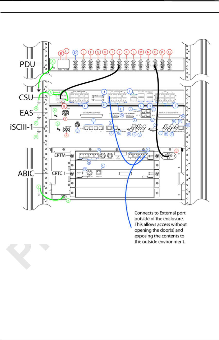
MC-Series ©2008 RadioFrame Networks, Inc. 4-7
Proprietary and Confidential Information
MC-Series Standard Capacity system998-1019-01 Rev X1
Figure 4.4 Connection between CSU and ABIC
Note: Figure 4.4 does not show all of the cabling.
4.2 Mounting Auxiliary Equipment
Follow vendor procedures for mounting the following auxiliary equipment:
• Powerplant
• Surge arrestors
• Environmental sensors
MC-Series Standard Capacity system 998-1019-01 Rev X1
4-8 ©2008 RadioFrame Networks, Inc. MC-Series
Proprietary and Confidential Information
4.3 Cabinet-to-Site Cabling
Follow the for installing the following wiring at the site, and then complete the
procedures in this section to complete the cabinet-to-site cabling. See Table 4.1 for
rear of the enclosure connections.
• Grounding
• T1/E1
• GPS surge arrestors (pre-installed)
• Surge arrestors for Tx/Rx/RX Div (pre-installed(
• EAS alarm cabling
• RF (Tx / Rx and Rx diversity)
• Power
• Air Conditioning (Power)
4.3.1 Matching Terminals for PDU and Ground
Select from the list of termination lugs in Table 4.1 (listed is the smallest
packaging size available); use two when connecting the powerplant to the PDU
and one when connecting the PDU ground to the top of the bus bar. Ground lug is
included.
Table 4.1 Power Lugs
Note: Crimp Tool needed: CT-1700
4.3.2 GPS surge arrestor
Table 4.2 shows the surge arrestor dimensions and performance specifications.
P/N AWG Config. Quantity (per Package)
LCD2-14A-Q 2 Straight 25
LCD2-14AF-Q 6 Straight 25
LCD6-14A-L 2 Right Angle 50
LCD6-14AF-L 6 Right Angle 50
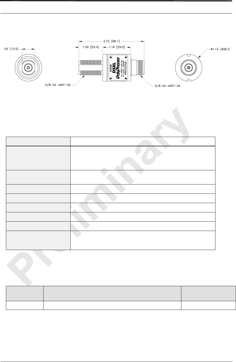
MC-Series ©2008 RadioFrame Networks, Inc. 4-9
Proprietary and Confidential Information
MC-Series Standard Capacity system998-1019-01 Rev X1
Figure 4.5 PolyPhaser RGT Broadband DC Pass Protector
4.3.3 Tx/Rx Surge Suppressor
Table 4.2 DSXL PolyPhaser Specifications
4.3.4 RF Feed-Throughs (N-type connectors)
Table 4.3 Specifications for N-Type Feed-Through Connectors
Application: Bulkhead mount weatherproof when installed
Surge/Frequency/VSWR:
IEC 61000-4-5 8/20 µS waveform
20kA@800 MHz to 2.0 GHz@≤1.1:1 VSWR
18kA@800 MHz to 2.3 GHz@≤ 1.1:1 VSWR
18kA@700 MHz to 2.7 GHz@≤ 1.1:1 VSWR
Insertion Loss: 500W@920MHz
(750W@50 ° C)
Continuous Power: ≤±3 V for 3kA@ 8/20 µS waveform
Let through Voltage: ≤±3 V for 3kA@8/20 µS waveform
Let Through Energy: ≤ 0.5 µJ for 3kA@8/20 µS waveform
Temperature: -40 ° C to +85 ° C Storage/Operating
Vibration: 1G @ 5 to 100 Hz
Environmental: Meets IEC 60529 IP65
Meets Bellcore #TA-NWT-000487
Procedure 4.11 Wind driven (120 mph/193 kph) Rain Intrusion Test
RadioFrame
Networks P/N Config. / Specs. SM Electronics P/N
514-0001-99 Terminator, N-M w/ chain 2 W 6 GHz, 18 dB max VSWR @ 6 GHz STN0610C
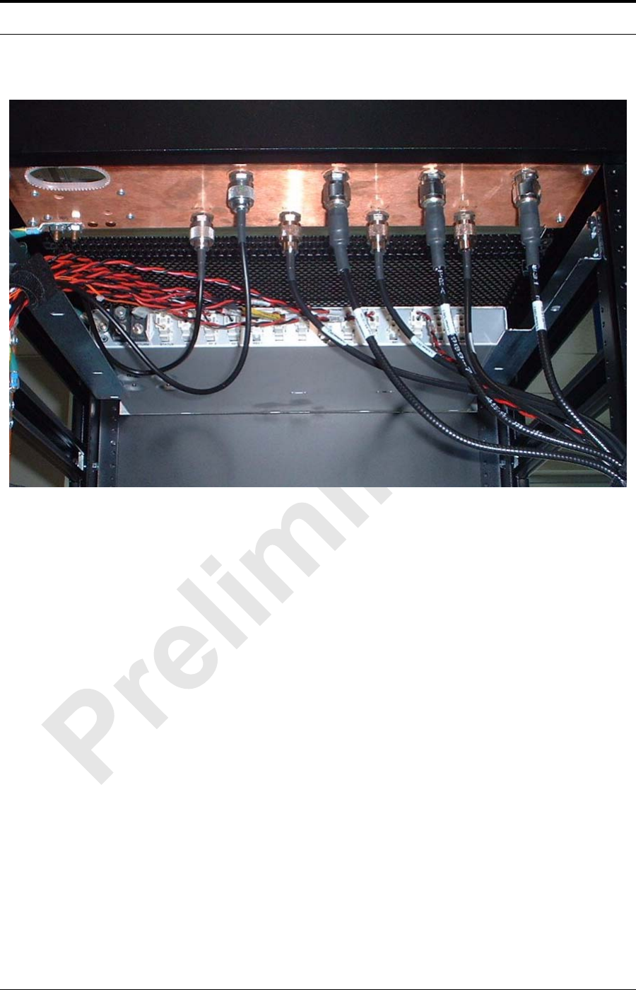
MC-Series Standard Capacity system 998-1019-01 Rev X1
4-10 ©2008 RadioFrame Networks, Inc. MC-Series
Proprietary and Confidential Information
Figure 4.6 Top of Rack (TOR) Rear of the cabinet, Bulkhead, Cabling and Equipment
4.3.5 Grounding
1 Ground the cabinet ground bar to the site according to instructions using 2-hole
terminal lug. Type is Panduit 2-hole, P/N LCD6-14A, or equivalent. Required crimp
tool is CT-1700.
2 Connect the site ground to the ground at the rear of the enclosure according to
installation procedures (see Figure 4.6 for ground location at the rear of the
enclosure).
4.3.6 T1/E1
1. Follow procedure for routing the site T1 cable through the rear of the enclosure
as shown in Figure 4.6.
2. Connect the T1/E1 cable to the CSU according to instructions.
4.3.7 GPS Surge Arrestor
Note: The Surge Arrestor comes installed in the
enclosure.
1. Connect each GPS surge arrestor to the GPS antenna coax according to
procedures.
MC-Series ©2008 RadioFrame Networks, Inc. 4-11
Proprietary and Confidential Information
MC-Series Standard Capacity system998-1019-01 Rev X1
4.3.8 EAS Alarm Cabling
1. Follow procedures for routing the alarm cables through the rear of the cabinet.
2. Connect the alarm cables to the back of the EAS:
EAS: USER ALARM / CONTROL
EAS: SYSTEM ALARM / CONTROL
3. Terminate the alarm cables to the two blocks on the backboard, making sure
that each cable is connected to its specific block.
4.3.9 RF (Tx / Rx and Rx diversity)
The MCSC system cabinet provides the following RF connectors at the rear of the
enclosure for connection to the site RF distribution system:
•Tx / Rx
•Rx Div
Connect the female N-type connectors to the onsite RF distribution system
(antenna, DAS, etc.).
4.3.10 Power
1. Connect the powerplant to the PDU using two (2) -hole terminal lugs. Type is
Panduit 2-hole, P/N LCD6-14A, or equivalent. Crimp tool needed: CT-1700.
Important:
RadioFrame Networks recommends placing a 20 A breaker between the
customer power supply and the MCSC system equipment.
Warning
Verify that all breakers in the PDU are in the OFF position prior to proceeding.
Leave them in the OFF position until instructed otherwise.

MC-Series Standard Capacity system 998-1019-01 Rev X1
4-12 ©2008 RadioFrame Networks, Inc. MC-Series
Proprietary and Confidential Information

MC-Series ©2008 RadioFrame Networks, Inc. 5-1
Proprietary and Confidential Information
MC-Series Standard Capacity system998-1019-01 Rev X1
Overview
This chapter describes the initial power up of the system after the
components have been installed and connected to all cabling.
Contents
5.1 Initial Powering Procedure....................................................................... 5-2
5.2 System Setup .......................................................................................... 5-3
5.3 Management—Datafill, Configuration and Optimization.......................... 5-8
5.3.1 Datafill.................................................................................................. 5-8
5.3.2 Parameters that Do Not Apply ............................................................. 5-9
5.3.3 Recommended Datafill Parameters..................................................... 5-9
5.3.4 rxTxGain = 0 ........................................................................................ 5-9
5.3.5 defaultTxPower.................................................................................. 5-10
5.4 System Manager, Configuration, and Optimization ............................... 5-10
5.4.1 Navigating System Manager.............................................................. 5-10
5.5 Functionality Test................................................................................... 5-13
5.6 Configuring the MC-Series Standard Capacity system.......................... 5-14
5.6.1 Navigating the System Configuration ................................................ 5-14
5.7 Optimization Procedures ....................................................................... 5-24
5.7.1 Local Performance Monitoring........................................................... 5-24
5.7.2 iDEN Uplink Analysis ......................................................................... 5-26
Chapter 5 Initial Power-up

MC-Series Standard Capacity system 998-1019-01 Rev X1
5-2 ©2008 RadioFrame Networks, Inc. MC-Series
Proprietary and Confidential Information
5.1 Initial Powering Procedure
1. Verify that the AC power to the Air Conditioner (A/C) is on and the A/C is
operating.
2. Verify that all breakers in the PDU are in the OFF position.
3. Ensure that the power switches on the iSCIII and the EAS are all in the OFF
position.
4. Using the breakers on the PDU, turn up the equipment by completing the
following steps, verifying that each component is operational before proceeding
to the next step.
5. Using the breaker on the PDU and the power switch on the front of the iSCIII,
turn up the iSCIII, and then verify that it is operational and that GPS lock has
been established before proceeding. For more information, refer to the Motorola
document Gen 3 Site Controller System Manual, 68P80801E30-O.
6. Using the breaker on the PDU and the power switch on the front of the EAS,
turn up the EAS, and then verify that it is operational before proceeding. For
more information, refer to the Motorola document Gen 3 Site Controller System
Manual, 68P80801E30-O.
7. Using the breaker on the PDU, turn up the CSU.
8. Configure the CSU according to the manufacturer's documentation and
standards.
9. Using the breaker on the PDU, turn up the ABIC and DRBS, and then verify that
both components are operational before proceeding.
10. Wait approximately 3 minutes for the following indications:
DRBS:
• The STATUS LED for each Group will turn green.
• The RADIOBLADE TRANSCEIVER STATUS LEDs will turn red and then
green for each present RadioBlade transceiver. If no RadioBlade
transceiver is present, the LED will not light. To verify the contents of the
DRBS, pull out the shelf (powering off is not required) and inspect the
RadioBlade transceivers and their respective status LEDs. Referring to
Figure 5.1, reinsert the DRBS. To do this, press up on one side rail
locking arm and press down on the other side rail locking arm, and then
push the unit into the cabinet.
CRIC
• The POWER and STATUS LEDs will turn red and then green. All ABIC
card LEDs will turn green.
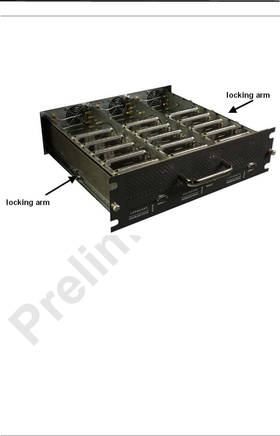
MC-Series ©2008 RadioFrame Networks, Inc. 5-3
Proprietary and Confidential Information
MC-Series Standard Capacity system998-1019-01 Rev X1
11. Using the breaker on the PDU, turn up the RF Shelf and then verify that the RF
Shelf is operational before proceeding. The POWER and ALARM LEDs on the
front of the RF shelf will turn green.
Figure 5.1 Location of DRBS Side Rail Locking Arms
Note: Image shows Group “A” installed, Group “B”
cover in place, and Group “C” with cover
removed. For the single sector MCSC system,
Group “B” and Group “C” are not installed.
5.2 System Setup
1. Connect the laptop to port 7 of the ABIC CRIC using an Ethernet (CAT-5) cable.
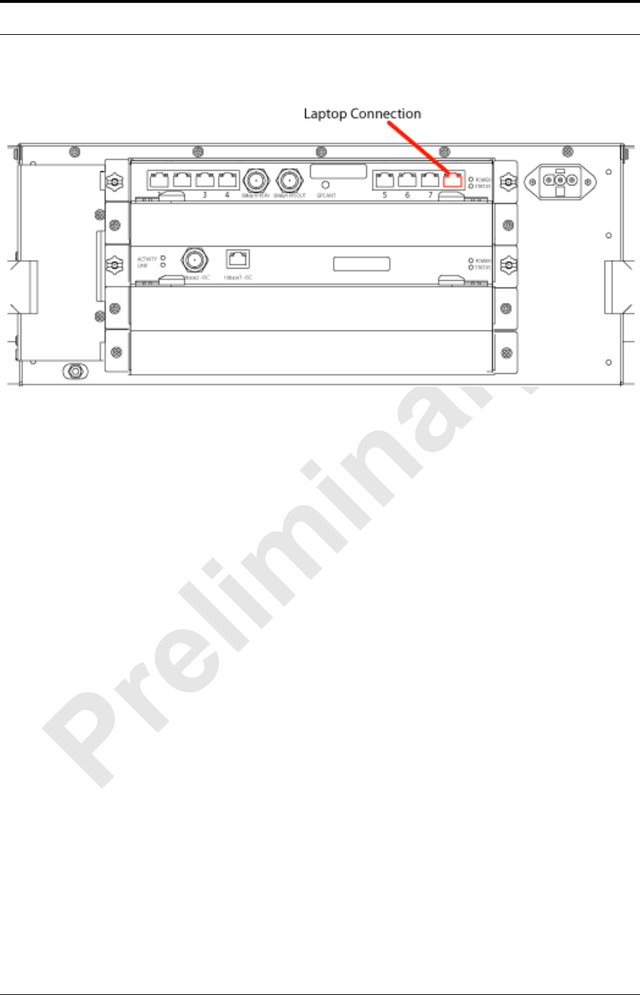
MC-Series Standard Capacity system 998-1019-01 Rev X1
5-4 ©2008 RadioFrame Networks, Inc. MC-Series
Proprietary and Confidential Information
Figure 5.2 Location of ABIC CRIC Laptop Connection Port
2. Set the laptop to DHCP. It will automatically assign an IP address.
3. Start System Manager.
4. Launch a browser session and enter the MCSC system IP address: http://
192.168.200.5. The System Manager Home page appears, which contains five
tabs to select from:
Home
Displays a welcome banner and a link for setting up users and changing the
MCSC system password.
System Configuration
Depicts the status of the ABIC and DRBS.
Alarms
Displays alarm information.
Performance Monitoring
Displays real-time performance information.
Diagnostics
Provides tools for testing.
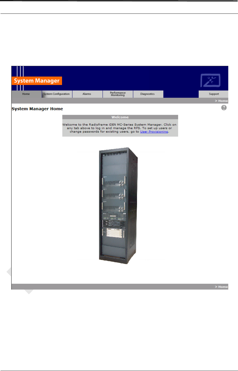
MC-Series ©2008 RadioFrame Networks, Inc. 5-5
Proprietary and Confidential Information
MC-Series Standard Capacity system998-1019-01 Rev X1
Support
Displays support information, including online help.
Figure 5.3 System Manager Welcome Screen
5. Log in to System Manager.
6. Select the System Configuration tab to display the login window. For User
Name, type Sysadmin (case sensitive). For Password, type Radioframe
(case sensitive), and then select OK. To change the password, refer to section
Changing the System Password “Changing the System Password”.
MC-Series Standard Capacity system 998-1019-01 Rev X1
5-6 ©2008 RadioFrame Networks, Inc. MC-Series
Proprietary and Confidential Information
Figure 5.4 System Manager Log-in Window
Note: Before proceeding to iDEN Configuration, it is a
good idea to ensure that the MCSC system
software is the latest released version. Refer to
section 5.6.1 .E. (Viewing Hardware and Software
Versions).
7. Select the iDEN Configuration link at the bottom of the System Configuration
page.
a. On the iDEN Configuration page, make sure the configuration agrees
with the site datafill and also the RF cabling. The sector assignments
must match the cabling inn the rear of the enclosure. All cab/pos values
must be associated with the appropriate sector. The MCSC system will
attempt to register all BRs with the cab/pos values selected in this
menu. An example configuration is shown in Figure 5.5. For more
information, refer to section 3.4 (iDEN Configuration).
MC-Series ©2008 RadioFrame Networks, Inc. 5-7
Proprietary and Confidential Information
MC-Series Standard Capacity system998-1019-01 Rev X1
Figure 5.5 iDEN Configuration Page
8. After iDEN configuration is updated (by clicking on Save Changes), a System
Reset is required. (Refer to section 3.4 (iDEN Configuration) if necessary.
9. Go to the Performance Monitoring page (section Local Performance Monitoring
“Local Performance Monitoring”) and confirm that are BRs that were intended to
be brought up are in the UEA state. If there are BRs that are not active, select
the Alarms tab and review the Active Alarm Manager for any active alarms.
For more information, refer to section 8.4.3 (System Manager Alarms).
10. Validate ToR output power or go to step 12 .
11. Connect the General Dynamics R2660 Series Communication System Analyzer
to the rear of the enclosure Tx /Rx1. Then set up the R2660 for iDEN Base
mode. Enter the control channel frequency for sector 1, and then measure the
output power of that frequency.

MC-Series Standard Capacity system 998-1019-01 Rev X1
5-8 ©2008 RadioFrame Networks, Inc. MC-Series
Proprietary and Confidential Information
Note: For specifications, refer to section 2.4.2
(Transmitter Performance Summary). The default
is +33 dBm per carrier, assuming that the datafill
parameter defaultTxPower is set to 9.5. If
necessary, adjust the datafill parameter (refer to
section 5.3.5 (defaultTxPower)).
12. Measure the SQE and frequency error for the control channel to see if they are
within specifications.
13. Verify that all BRs have the same output power.
For each channel, enter the frequency into the R2660 and verify that the SQE,
frequency error, and power level are all within specifications (refer to Table
2.9).
14. Repeat steps 7 through 13 as needed for each sector.
15. Review the Active Alarm Manager for any un-cleared alarms.
Refer to the section (System Manager Alarms) for more information.
5.3 Management—Datafill, Configuration and Optimization
This section describes configuration techniques that affect the behavior of the MCSC
system. The Datafill section covers the datafill parameters as they differ from the
Motorola EBTS. Section System Manager, Configuration, and Optimization covers
configuration options using System Manager, with sections Navigating System
Manager and Configuring the MC-Series Standard Capacity system introducing basic
operations and Optimization Procedures presenting optimization procedures.
The MCSC system is designed for compatibility with the Motorola EBRC and QUAD
Base Radios (BRs). However, due to architecture differences between the two
systems, not all datafill parameters apply equally to the MCSC system.
5.3.1 Datafill
This section describes only those datafill parameters that need to be taken into
consideration when used with the MCSC system. Any datafill parameter not
described here can be assumed to behave identically to the Motorola EBTS. This
section includes:
• 5.3.2 (Parameters that Do Not Apply) Parameters that have no effect on the
MCSC system
• 5.3.3 (Recommended Datafill Parameters) Parameters that RadioFrame
Networks supports, but which need to be setup differently from the typical
setup for a Motorola BR

MC-Series ©2008 RadioFrame Networks, Inc. 5-9
Proprietary and Confidential Information
MC-Series Standard Capacity system998-1019-01 Rev X1
5.3.2 Parameters that Do Not Apply
The following parameters have no effect on the MCSC system. There is no
functional equivalent in the MCSC system, and as such the parameters can be
ignored.
A. combinerType
This parameter specifies the type of combiner used to connect the cells Base
Radios to the antenna. The options are hybrid and cavity. The MCSC system is
similar to a cavity type combiner physically but it does not have the same
frequency limitations as the cavity combiner that this parameter is used for.
5.3.3 Recommended Datafill Parameters
The following parameters need to be set differently than what is currently set with
Motorola BR. These settings are not required but recommended for best
operation.
A. PCC
The power control constant is broadcast on the BCCH and is used by the MS
to calculate a target value for its transmit power. For Indoor Pico and Micro-Cell
applications this value will vary depending upon the RF environment (i.e., if
used outdoors the value will be quite different from an indoor scenario). For the
MCSC system, the setting of this parameter depends on what is connected
between the MCSC system and the antenna. The default value should be
calculated in accordance with Motorola guidance detailed in the Datafill
Parameter Guide. Lowering this parameter forces the mobile to operate at
fairly low Tx level thus conserving battery life. In cases where the MCSC
system is connected to a DAS, the gains and losses of the paths should be
taken into consideration. Additionally the level of uplink interference should be
considered when determining this value.
B. Pto (transmit power)
The Cells outbound transmit power referenced at the output of the RF
Distribution System Antenna Port. It is used as a reference point value when
computing the link budget of the system. RadioFrame Networks recommends
that the value of this parameter be set appropriate to the TOR output power,
which is determined by the defaultTxPower parameter (see below).
5.3.4 rxTxGain = 0
This parameter is the difference in gain between the receiver and transmit
antenna paths expressed in dB. The MCSC system does not use this parameter
directly.

MC-Series Standard Capacity system 998-1019-01 Rev X1
5-10 ©2008 RadioFrame Networks, Inc. MC-Series
Proprietary and Confidential Information
5.3.5 defaultTxPower
Note: Refer to release notes for the proper range
information.
This is the average output power of the PA, measured at the RF connector of the
BR. For the MCSC system, this parameter can be used to adjust the output power
of the system. The gain at the shelf is fixed and cannot be altered. The MCSC
system has a different range of output levels than a standard Motorola EBTS, and
as such, these values will map to a different set of actual Tx output power levels.
Refer to the Datafill Guide for the values and more information.
5.4 System Manager, Configuration, and Optimization
5.4.1 Navigating System Manager
A. Logging into System Manager
1. Connect a laptop computer to port 7 of the ABIC CRIC using an Ethernet
(Cat-5) cable.
2. Start System Manager by typing the IP address of the MCSC system into
Internet Explorer (default 192.168.200.5).
3. The System Manager Home page appears and displays five tabs to select
from to set up and monitor the RadioFrame MCSC system.
MC-Series ©2008 RadioFrame Networks, Inc. 5-11
Proprietary and Confidential Information
MC-Series Standard Capacity system998-1019-01 Rev X1
Figure 5.6 System Manager Home Page
Home
Displays a welcome banner and a link for setting up users and changing the
MC-Series system password.
System Configuration
Depicts the status of the ABIC, DRBS, and RadioBlade transceivers.
Alarms
Displays alarm information.
Performance Monitoring
Displays real-time performance information.
MC-Series Standard Capacity system 998-1019-01 Rev X1
5-12 ©2008 RadioFrame Networks, Inc. MC-Series
Proprietary and Confidential Information
Diagnostics
Provides tools for testing.
Support
Displays support information, including online help.
4. To log in, select any tab.
5. For User Name, type the MCSC system user name.
6. For Password, type the MCSC system password.
7. To save the password, check ‘Save this password in your password list’
check box.
8. Select OK.
Figure 5.7 Network Password Pop-up Dialog Box
B. Changing the System Password
1. Select the Home tab, and then select the User Provisioning link.
2. For Select User Name, choose the appropriate system title from the drop-
down menu.
3. Typically, choose Sysadmin (Entire System) unless instructed to do
otherwise.
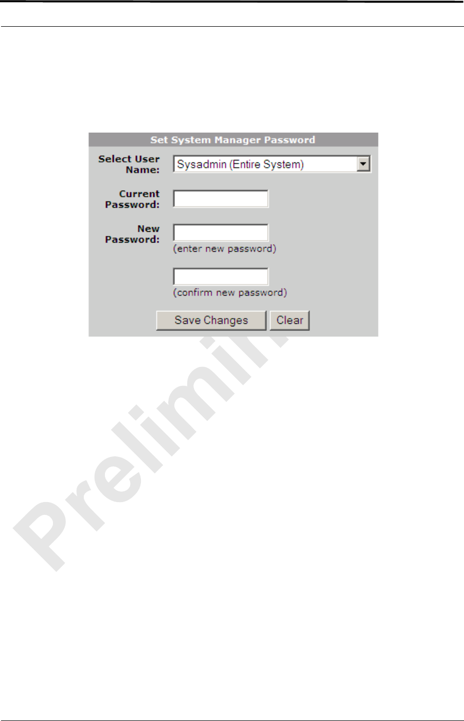
MC-Series ©2008 RadioFrame Networks, Inc. 5-13
Proprietary and Confidential Information
MC-Series Standard Capacity system998-1019-01 Rev X1
4. Type the Current Password.
5. Type the New Password and confirm it, then select Save Changes.
Figure 5.8 Set System Manager Password Dialog Box
5.5 Functionality Test
RadioFrame Networks recommends that a certification process be completed to
ensure proper operational performance and to verify the integrity of the following
services:
• Voice quality for 3:1 Interconnect Voice
• Voice quality for 6:1 Private Group Dispatch Voice
• Call setup reliability for 3:1 Interconnect Voice
• Call setup reliability for 6:1 Private and Group Dispatch Voice
• Call stability for all of the above voice services
• Connection quality, stability, delay and perceived throughput for the Packet
Data service
• Connection setup reliability for Packet Data
• Idle SQE quality and variation
• Call up SQE quality and variation
• Short Message Service
• Handover and cell reselection
• Performance will also be validated by collecting at least one week of

MC-Series Standard Capacity system 998-1019-01 Rev X1
5-14 ©2008 RadioFrame Networks, Inc. MC-Series
Proprietary and Confidential Information
performance statistical data
Refer to Appendix C (Functionality Test Procedures) for procedures to conduct
functionality testing.
Note: MCSC system does not support Circuit-Switched
data.
5.6 Configuring the MC-Series Standard Capacity system
5.6.1 Navigating the System Configuration
The System Configuration page displays icons depicting the ABIC and the DRBS
(see Figure 5.1). The colored bar beneath each icon represents the status of that
component as listed in Table 5.1.
MC-Series ©2008 RadioFrame Networks, Inc. 5-15
Proprietary and Confidential Information
MC-Series Standard Capacity system998-1019-01 Rev X1
Figure 5.9 BIC Configuration Page Showing ABIC and DRBS Status
Table 5.1 Status Color Interpretations
Color Status Indicator Description
Green Active The component is installed, configured and operational.
Yellow Inactive The component is installed but has not been configured.
Gray Inactive Unit not installed or Port disabled
Red Alarm The component has returned an alarm condition. Refer to 8.4.3 (System
Manager Alarms) for specific alarm conditions.

MC-Series Standard Capacity system 998-1019-01 Rev X1
5-16 ©2008 RadioFrame Networks, Inc. MC-Series
Proprietary and Confidential Information
1. To view configuration information for a component, select its icon.
2. The ABIC configuration page displays the device name, IP address, building
address and other pertinent information.
3. To return to a previous page, select the component pathname at the top of the
tab (System Configuration>BIC…), or to return to the ABIC configuration page,
select the System Configuration tab at any time.
A. Viewing the Status of the RadioBlade Transceivers
The DRBS Status, RadioBlade Alarms, and RadioBlade Control (formerly
RadioBlade Statistics) pages show the MCRB. Select the DRBS STATUS link
at the bottom of the System Configuration page. The DRBS Status page
displays an icon for each RadioBlade transceiver installed in the DRBS, and
indicates the status of the RadioBlade transceiver and whether or not it is
locked. At the top of the page are three icons representing the status of each
group (A and C) in the DRBS.
MC-Series ©2008 RadioFrame Networks, Inc. 5-17
Proprietary and Confidential Information
MC-Series Standard Capacity system998-1019-01 Rev X1
Figure 5.10 RadioBlade Status Page
B. Locking and Unlocking a RadioBlade Transceiver
Select the RadioBlade transceiver icon or the RadioBlade Control link at the
top of the DRBS Status page. The RadioBlade Control page displays the
following information for each iDEN RadioBlade transceiver:
• RadioBlade transceiver Slot (1-24)
•RB ID
•State
• RB PLL Status
• Carrier ID

MC-Series Standard Capacity system 998-1019-01 Rev X1
5-18 ©2008 RadioFrame Networks, Inc. MC-Series
Proprietary and Confidential Information
• Transmit Frequency
• Cabinet
• Position
• Locked/Unlocked
To lock or unlock a RadioBlade transceiver, select the icon in the Locked/Unlocked
column.

MC-Series ©2008 RadioFrame Networks, Inc. 5-19
Proprietary and Confidential Information
MC-Series Standard Capacity system998-1019-01 Rev X1
Figure 5.11 RadioBlade Control Page
C. RadioBlade Alarms Page
The RadioBlade Alarms Page displays information for RadioBlade transceivers
either on a per-channel or per-blade basis, as appropriate for that type of
alarm. This page is shown in Figure 5.12.
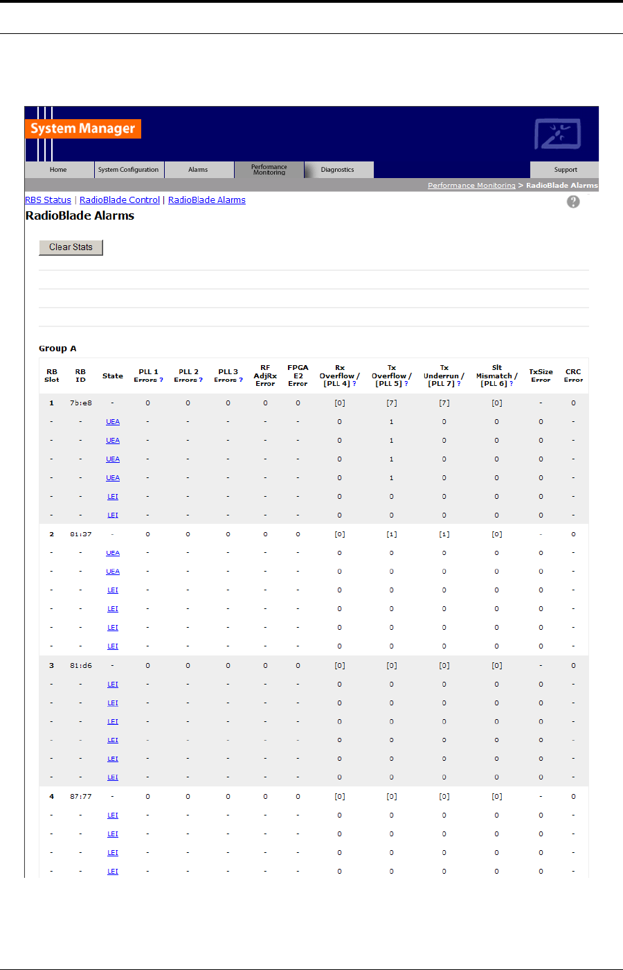
MC-Series Standard Capacity system 998-1019-01 Rev X1
5-20 ©2008 RadioFrame Networks, Inc. MC-Series
Proprietary and Confidential Information
Figure 5.12 RadioBlade Alarms Page

MC-Series ©2008 RadioFrame Networks, Inc. 5-21
Proprietary and Confidential Information
MC-Series Standard Capacity system998-1019-01 Rev X1
D. Changing the Device Name, IP Address or Building Location
The System Configuration page displays the configuration for the selected
component (BIC and DRBS) including the Device Name, IP Address, and
Building Address—this information can be changed at any time. For the ABIC,
this page also displays External IP Configuration, the information that systems
outside the MCSC system use to recognize it, including the Default Gateway
(the IP address of the CSU).
1. Select the icon of the component to be changed.
2. For Device Name, enter up to 31 alphanumeric characters to uniquely
identify the component.
3. The IP Address is assigned during the installation of the MCSC system, and
doesn’t need to be changed.
4. For Building Address, enter up to 3,000 alphanumeric characters specifying
the location of the component. Enter information such as the street address,
mailing address, building and other site information, as well as the building
floor, Telco closet and cabinet location.
5. Select Save Changes.

MC-Series Standard Capacity system 998-1019-01 Rev X1
5-22 ©2008 RadioFrame Networks, Inc. MC-Series
Proprietary and Confidential Information
Figure 5.13 System Configuration Page, ABIC Selected Component
E. Viewing Hardware and Software Versions
Select the Software Version Information link on the System Configuration
page. The Software Version Information page depicts each component in the
MCSC system, and each board installed in each component. For each board
the page lists:
• MAC—the MAC address
• HW—hardware version
• FPGA—Field Programmable Gate Array version (manufacturer defined)
• ROM—software loaded at time of shipment
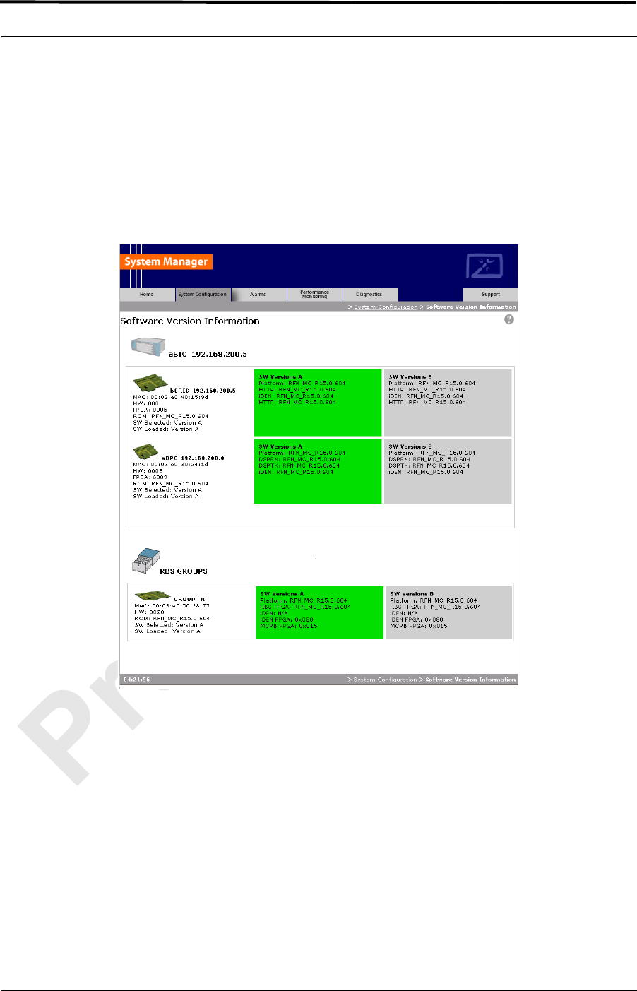
MC-Series ©2008 RadioFrame Networks, Inc. 5-23
Proprietary and Confidential Information
MC-Series Standard Capacity system998-1019-01 Rev X1
• SW Selected—currently selected software version, A or B
• SW Loaded—currently loaded software version, A or B
• SW Versions A—Software version loaded in partition A
• SW Versions B—Software version loaded in partition B
Figure 5.14 Software Version Information Page
F. Changing the iDEN Configuration
The MCSC system operates as a series of base radios. Each RadioBlade
transceiver in the MC-Series is assigned a BR ID and sector (1, 2 or 3). And,
each BR in the MCSC system is assigned a default cabinet position in the site
datafill.
To change the default cabinet position:
1 Select the iDEN Configuration link at the bottom of the System Configuration tab.
2 Enter the Cabinet and Position for the specified BR(s).
3 Select any Quad BRs (only one per group), according to site datafill parameters.
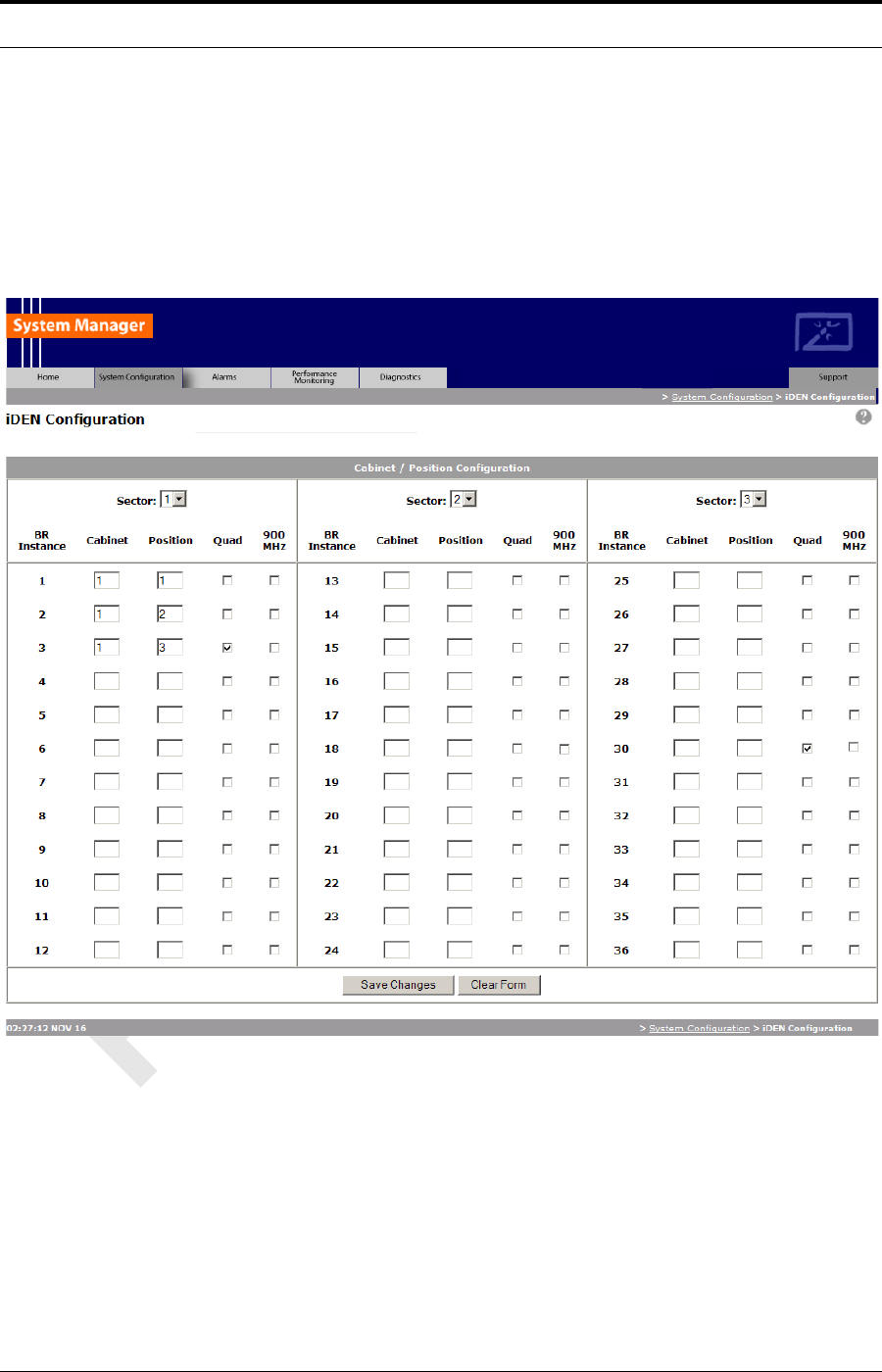
MC-Series Standard Capacity system 998-1019-01 Rev X1
5-24 ©2008 RadioFrame Networks, Inc. MC-Series
Proprietary and Confidential Information
4 In Figure 5.15, one Quad BR has been selected: BR Instance 5 Cabinet 3
Position 5, in the first group. In this example, BRs 5 through 8 make up the Quad
BR.
5 Select the Save Changes button to save the changes.
Figure 5.15 iDEN Configuration Page
Note: The Sector 2 and Sector 3 groups of the DRBS is
not available for use in the Base system.
5.7 Optimization Procedures
5.7.1 Local Performance Monitoring
1. In System Manager, select the Performance Monitoring tab.
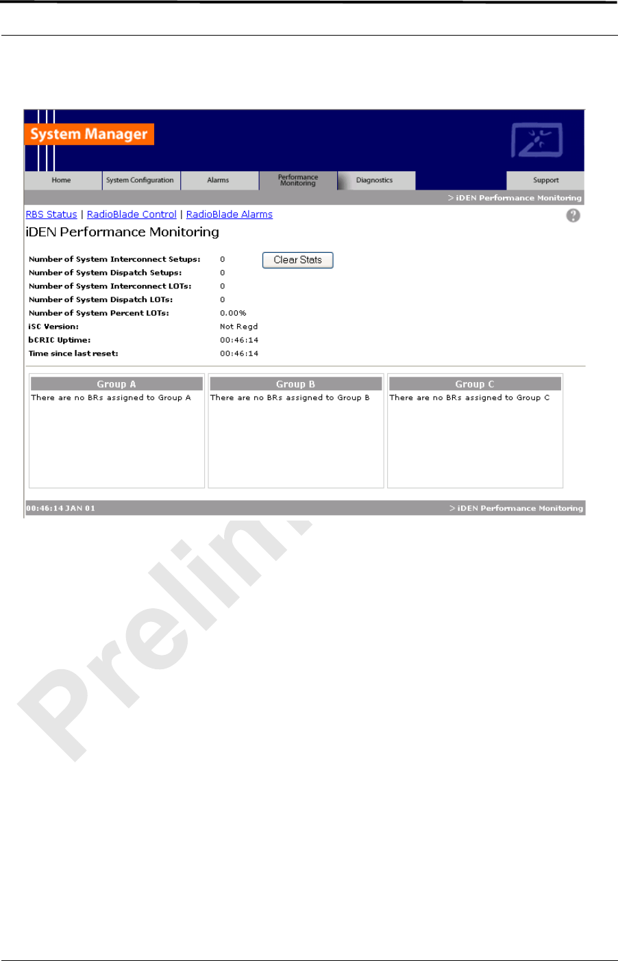
MC-Series ©2008 RadioFrame Networks, Inc. 5-25
Proprietary and Confidential Information
MC-Series Standard Capacity system998-1019-01 Rev X1
Figure 5.16 Operational Status—Performance Monitoring Page
Note: Group “B” is not supported on the MCSC system
main cabinet.
2. Select a BR icon to display the Base Radio Performance Statistics page.
3. Verify that the mean INI is within normal range (will vary depending on what is
connected between TOR and the antenna).
4. Verify that the % poor SQE does not exceed 2% on a substantial number of
packets (i.e., greater than 10,000 packets).
5. Repeat steps 2 through 4 for each BR in the system.
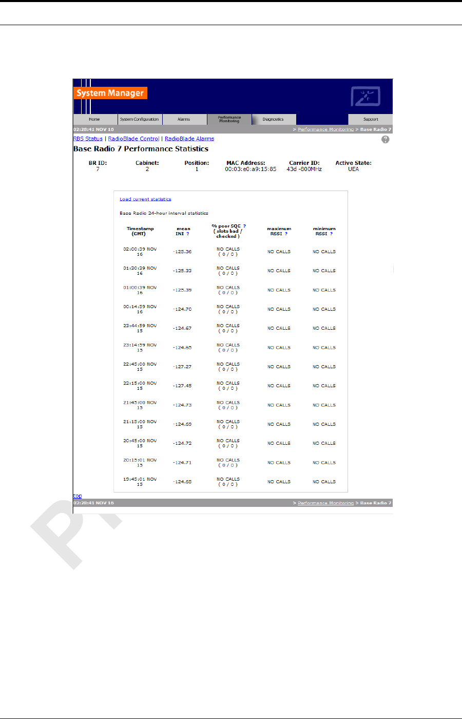
MC-Series Standard Capacity system 998-1019-01 Rev X1
5-26 ©2008 RadioFrame Networks, Inc. MC-Series
Proprietary and Confidential Information
Figure 5.17 Base Radio Performance Statistics Page
5.7.2 iDEN Uplink Analysis
RadioFrame Networks’ iDEN Uplink Analysis Tool plots the Mean RSSI, Mean I+N
and SQE for the last 80 seconds for the BR channel which has been selected.
Figure 5.18 shows the System Manager page, accessible from the Diagnostics
tab. The analyzer prints the following information:
• Mean RSSI (----- red): Average Received Signal Strength Indicator.
• Mean I+N (----- magenta): Average Interference Plus Noise.
•SQE (
-----yellow): Signal Quality Estimate.

MC-Series ©2008 RadioFrame Networks, Inc. 5-27
Proprietary and Confidential Information
MC-Series Standard Capacity system998-1019-01 Rev X1
Figure 5.18 Uplink Analyzer Page
A. To use the Uplink Analysis Tool:
1. Select a radio and channel:
a. Select the base radio from the BR ID menu. Select the channel from the
Logical Channel menu.
b. Click Update Graph to clear the screen and start a new graph with the
new radio and channel.
c. Click Clear Graph to reset the graph and start fresh with the current
base radio and channel.
2. Reset the graph by clicking Clear Graph, and start fresh with the current
base radio and channel.
Note: The Carrier ID is displayed in Hex for the BR
chosen.
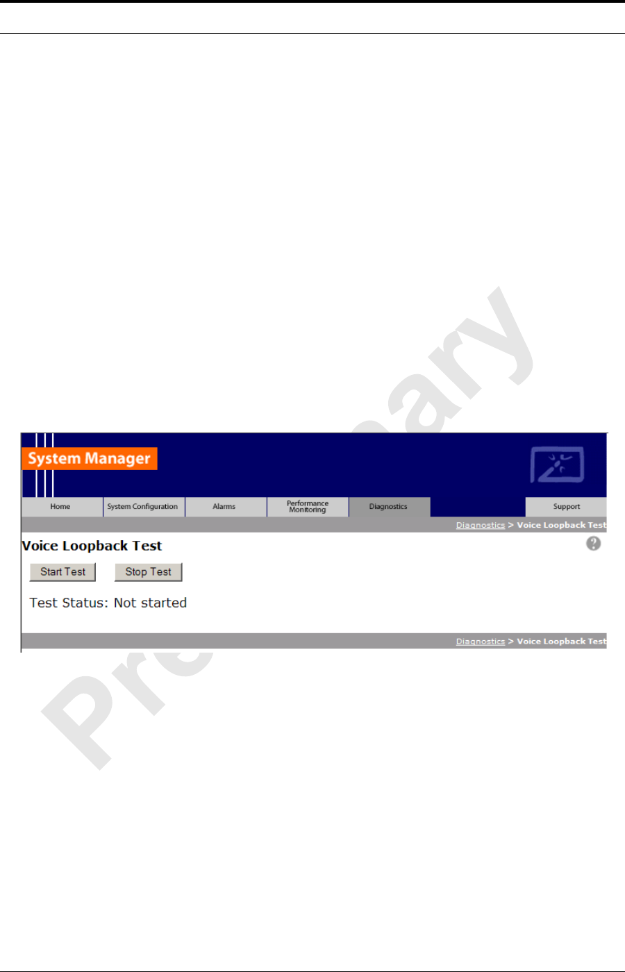
MC-Series Standard Capacity system 998-1019-01 Rev X1
5-28 ©2008 RadioFrame Networks, Inc. MC-Series
Proprietary and Confidential Information
B. Voice Loopback Diagnostic Test
The Voice Loopback Diagnostic test provides the ability to loop all inbound
voice traffic back out on the same logical channel for a given BR. This allows a
person with a mobile to do uplink and downlink testing on a given BR without
having to call someone else to monitor voice quality. The person on the Mobile
simply speaks into the mobile and can hear his or her own voice.
Note: This test can also be used to isolate voice quality
issue to the backhaul.
To use the Voice Loopback Test feature:
1. Click Start Test on the Voice Loopback Diagnostic Test Page to start the
voice packet loopback. The first call, and only the first call, set up after Start
Test is selected will be looped back. If a call other than the tester’s happens
to be set up after Start Test is selected and before the tester has the
opportunity to set up the call, the other call will be looped back.
Figure 5.19 Voice Loopback Diagnostic Test Page
2. Speak into the handset, and listen to evaluate voice quality.
3. Click Stop Test to terminate the test.
The loopback will persist on the selected BR until the Stop Test button is
selected.
The Test Status line will give a brief indication of the test state (Not Started;
Waiting for Call Setup; Started).
C. System Parameter Information Page
The System Parameter Information Page displays the type 1 iDEN System
Parameter Information that comes across the BCCH chain.
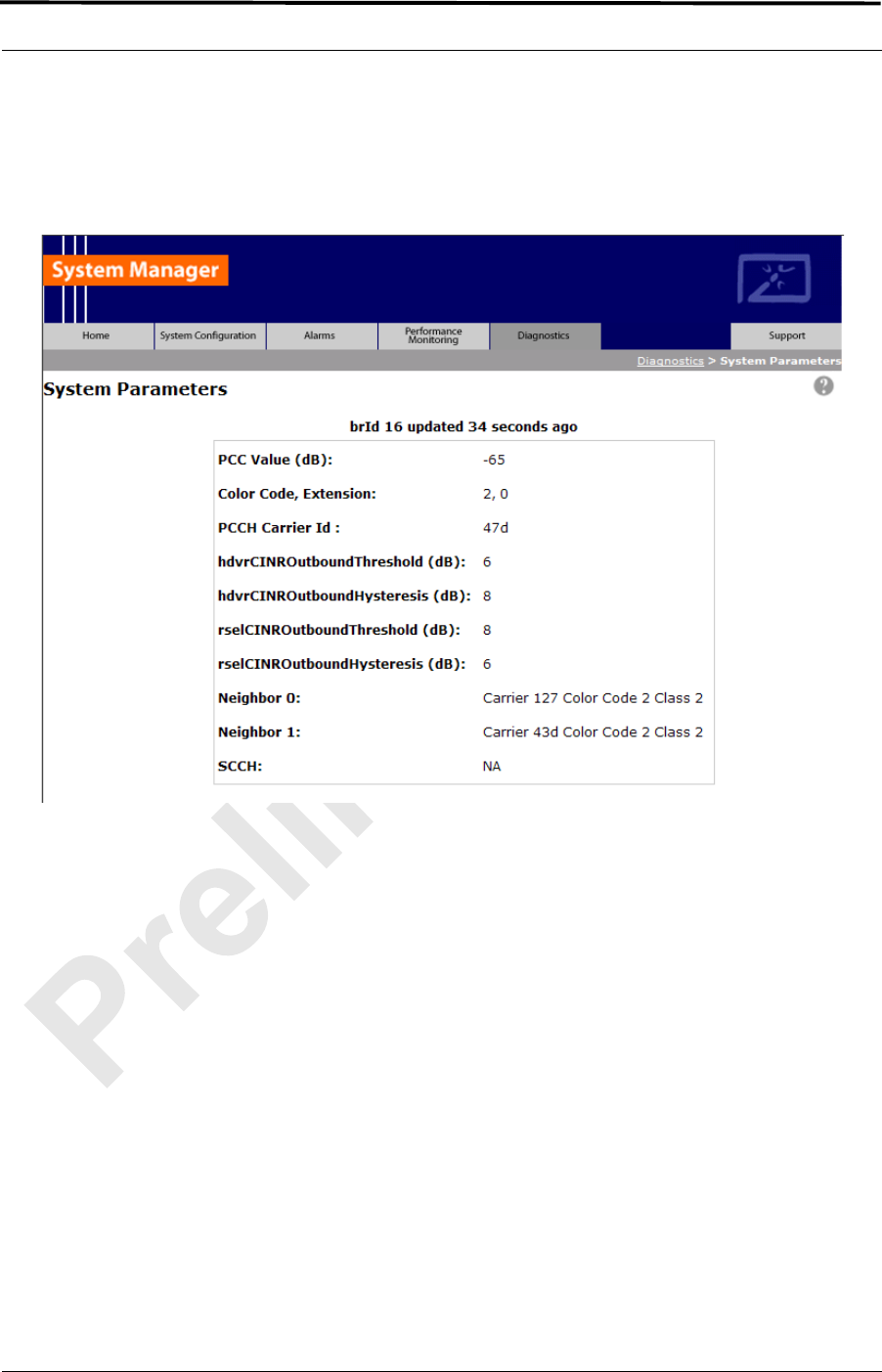
MC-Series ©2008 RadioFrame Networks, Inc. 5-29
Proprietary and Confidential Information
MC-Series Standard Capacity system998-1019-01 Rev X1
Note: Only a subset of the BCCH information is
currently displayed.
Figure 5.20 System Parameter Information Page
Note: The datafill parameters
“hdvrCINROutboundThreshold” and
“rconCINROutboundThreshold” are modified in
the iSCIII per the iDEN specification.
The value displayed as “rsel_threshold” in the
System Parameter Information page reflects the
observed BCCH value, which is the datafill value
of “rconCINROutboundThreshold”, offset by + 14
dB. The value displayed as “hdvr_threshold” is
the datafill value “hdvrCINROutboundThreshold”,
offset by
+ 14 dB. For example, in the screen shot shown
in Figure 5.20, the datafill value corresponding to
“hdvr_threshold” would be equal to 6 (i.e., 6 +14 =
20).

MC-Series Standard Capacity system 998-1019-01 Rev X1
5-30 ©2008 RadioFrame Networks, Inc. MC-Series
Proprietary and Confidential Information
System Manager is the MCSC system web-based interface. System Manager
provides status, performance, and alarm information for the MCSC system and
its components, as well as diagnostic tools and online help. When new
releases of System Manager are provided, download the new release as
described in section 6.1 (Upgrading MC-Series Standard Capacity system
Software).
If any of the following information is changed in System Manager, also note
those changes on the Equipment Inventory or site as-built documentation:
• Physical location
• IP addresses
• Port connections
• Sector locations

MC-Series ©2008 RadioFrame Networks, Inc. 6-1
Proprietary and Confidential Information
MC-Series Standard Capacity system998-1019-01 Rev X1
Overview
The MCSC system is shipped with the latest software installed. With each
new software release, RadioFrame Networks provides its customers with
the new software and accompanying information in the RadioFrame
Networks Customer Release Notes.
Contents
6.1 Upgrading MC-Series Standard Capacity system Software .................... 6-2
6.1.1 Download MC-Series Standard Capacity system Software to the Laptop.
6-2
6.1.2 Download FTP Server Software to the Laptop Computer ................... 6-2
6.2 Update the MC-Series Standard Capacity system Software ................... 6-8
6.2.1 Verify the Software Download.............................................................6-11
6.3 Rollback to the previous version of software ......................................... 6-12
6.4 Performing a System Reset................................................................... 6-12
Chapter 6 System Configuration Changes

MC-Series Standard Capacity system 998-1019-01 Rev X1
6-2 ©2008 RadioFrame Networks, Inc. MC-Series
Proprietary and Confidential Information
6.1 Upgrading MC-Series Standard Capacity system Software
The following procedures describe how to upgrade MCSC system software. System
Manager contains two separate partitions in which to install software: active and
inactive. This provides the means to revert back to a previous version of system
software if required.
6.1.1 Download MC-Series Standard Capacity system Software to the
Laptop
Note: If the laptop already contains the docs, platform
and iden directories for the system software in
the root, you may wish to delete these directories
and all of their contents before downloading and
extracting the latest system software. This way
you can ensure a complete clean install.
Download the latest system software, a self-extracting zip file, from:
http://www.radioframenetworks.com/partners
1. Navigate to the support pages. If you have not visited the RadioFrame
Networks PartnerWeb site, you will be asked to register. Use your e-mail
address and create a password.
2. Once your account is authenticated, install/extract the zip file directly into the C:/
drive on the laptop. The install creates three directories at the root level: docs,
platform and iden.
6.1.2 Download FTP Server Software to the Laptop Computer
You will need an FTP server application running on the laptop computer. If one is
already installed, you can skip to section 6.2 (Update the MC-Series Standard
Capacity system Software). The following procedure installs a shareware program
(Wftpd.exe) and configures it correctly. Use the method for your version of
Windows.
A. Windows XP Method
Windows XP is capable of correctly configuring Wftpd.exe if you follow these
steps.
1. Download Wftpd.exe, a self-extracting zip file, from:
http://www.radioframenetworks.com/partners
or from
http://www.wftpd.com/
2. Open the zip file with your archive/compress/extract utility (e.g., WinZip).
3. Extract to your Windows drive root directory (e.g., C:\).
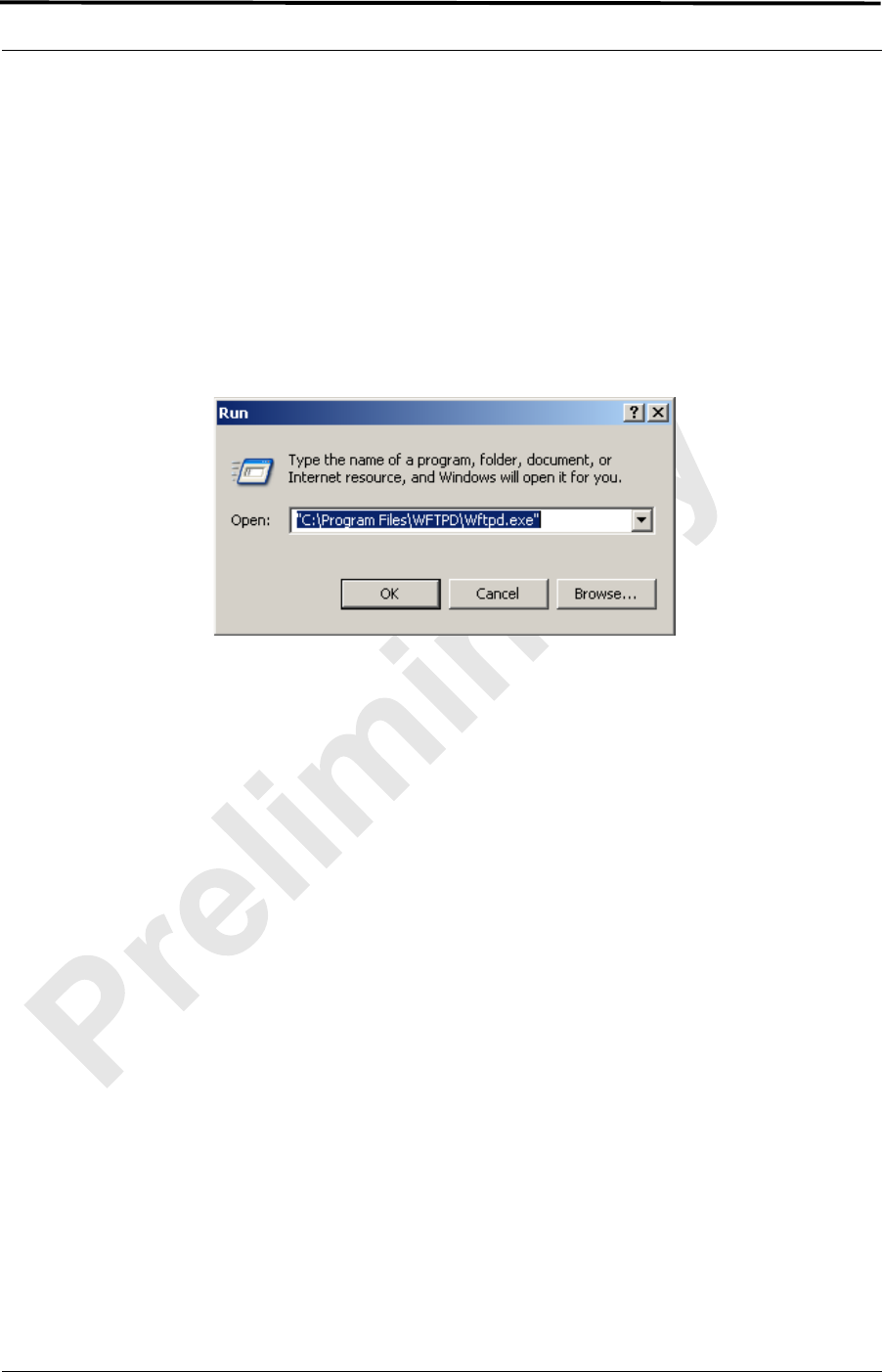
MC-Series ©2008 RadioFrame Networks, Inc. 6-3
Proprietary and Confidential Information
MC-Series Standard Capacity system998-1019-01 Rev X1
4. From the Windows Start menu, select Run.
5. Click Browse... in the Run dialog box and browse to
C:\Program Files\WFTPD
(Windows XP should have placed the properly configured executable
Wftpd.exe in Program Files\WFTPD. If you do not see it there, you need to
follow the Windows 2000 configuration method.)
6. In the Browse dialog box, select the file Wftpd.exe and click Open.
Figure 6.1 Executing Wftpd from the Windows XP Laptop Run Dialog Box
7. Click OK in the Run dialog box to start WFTPD.
8. Check configuration as follows: Navigate to the Security menu and select
Users/Rights... . In the User/Rights Security dialog box, select board from
the User Name drop down list.
9. Now proceed to the section 6.2 (Update the MC-Series Standard Capacity
system Software) to upgrade the system software.
B. Windows 2000 Method
1. Download Wftpd.exe, a self-extracting zip file, from:
http://www.radioframenetworks.com/partners
or from
http://www.wftpd.com/
2. Open the zip file with your archive/compress/extract utility (e.g., WinZip).
3. Extract to your Windows drive root directory (e.g., C:\).
4. From the Windows Start menu, select Run.
5. Open the FTP Server – enter C:\Wftpd.exe in the dialog box and click OK.
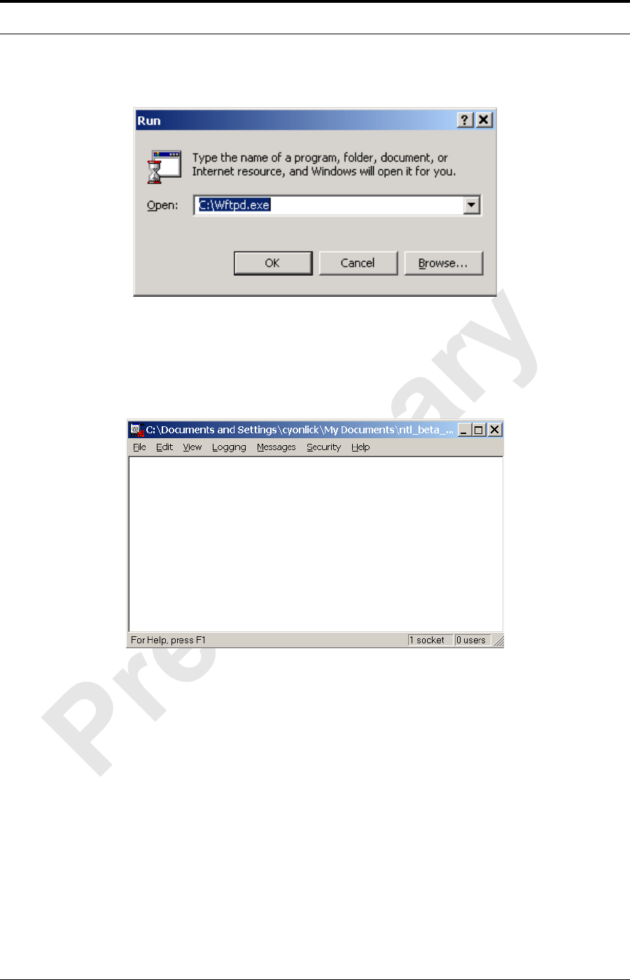
MC-Series Standard Capacity system 998-1019-01 Rev X1
6-4 ©2008 RadioFrame Networks, Inc. MC-Series
Proprietary and Confidential Information
Figure 6.2 Executing Wftpd from the Windows 2000 Laptop Run Dialog Box
6. The configuration in Figure 6.3 is for Wfptd:
Figure 6.3 Wftptd Settings (Bottom of Screen Shot)
7. From the Security menu, select General, configure the General Security
page as shown in Figure 6.4 and then select OK.
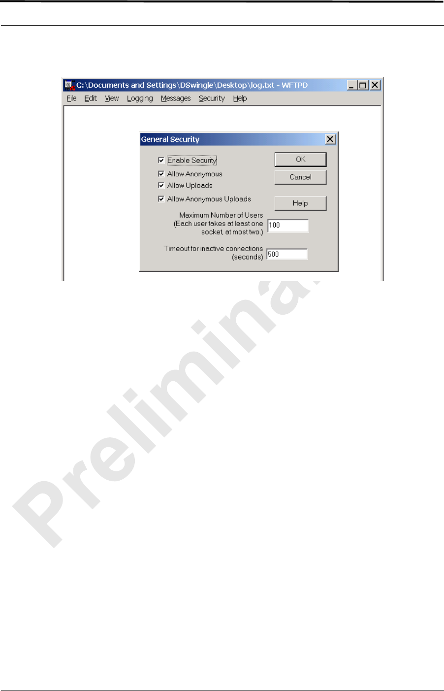
MC-Series ©2008 RadioFrame Networks, Inc. 6-5
Proprietary and Confidential Information
MC-Series Standard Capacity system998-1019-01 Rev X1
Figure 6.4 General Security Dialog Box Settings
8. From the Security menu, select User/rights, and for User Name select
anonymous from the drop down menu, and then select the Rights<< button
and verify that the settings are the same as shown in Figure 6.5.
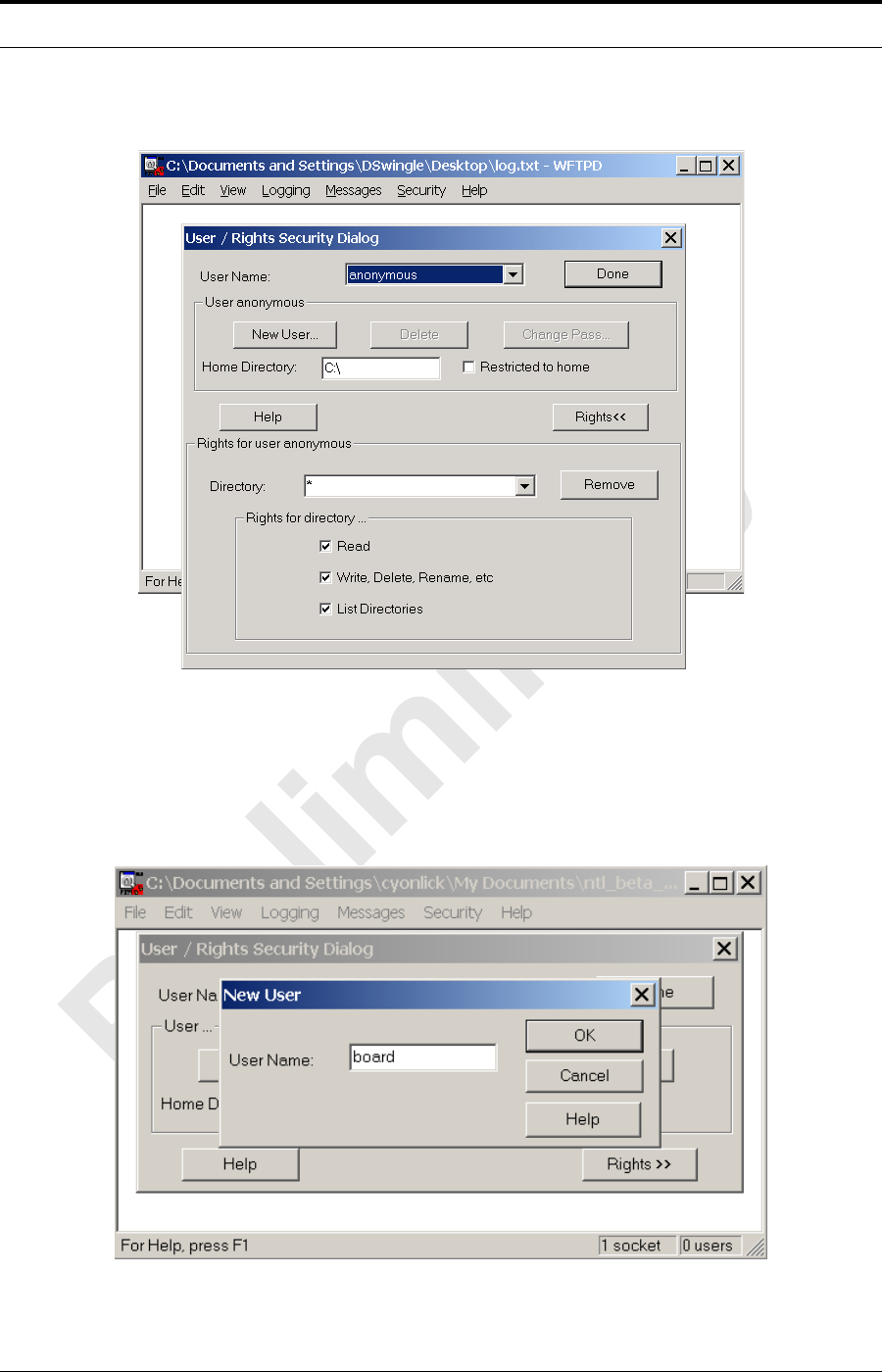
MC-Series Standard Capacity system 998-1019-01 Rev X1
6-6 ©2008 RadioFrame Networks, Inc. MC-Series
Proprietary and Confidential Information
Figure 6.5 User / Rights Security Dialog Box Settings
9. Select the New User… button, and then for User Name type board in the
text box, and then select OK.
Figure 6.6 New-User Name
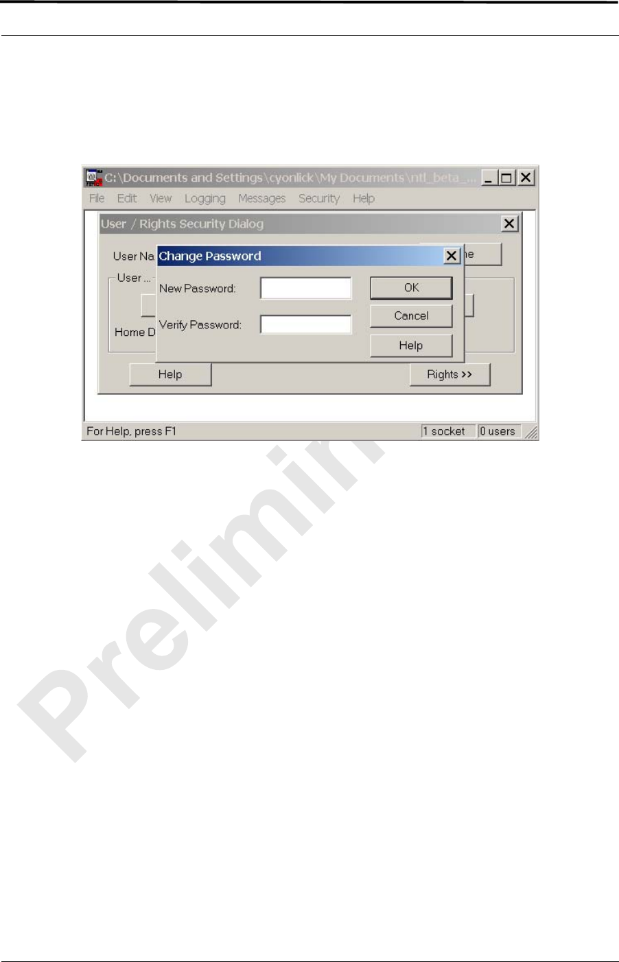
MC-Series ©2008 RadioFrame Networks, Inc. 6-7
Proprietary and Confidential Information
MC-Series Standard Capacity system998-1019-01 Rev X1
10. For New Password type wind, then retype wind in the Verify Password
text box, and then select OK.
Figure 6.7 Password
11. The User/Rights Security dialog box reappears, and the User Name is now
set to board. Select the Rights button and verify that the settings are the
same as shown below, and then select Done.
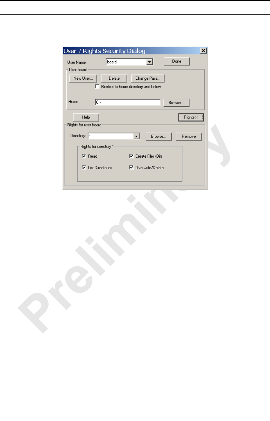
MC-Series Standard Capacity system 998-1019-01 Rev X1
6-8 ©2008 RadioFrame Networks, Inc. MC-Series
Proprietary and Confidential Information
Figure 6.8 User Name Set in User/Rights Security Dialog Box
12. Now proceed to the next section to upgrade the system software.
6.2 Update the MC-Series Standard Capacity system Software
The following procedure assumes that the MCSC system is currently running at least
the RadioFrame Networks 15.0 release, and that the system is to be upgraded to the
RadioFrame Networks MC 15.0 MCSC system software load. If this is not the case,
the system must first be upgraded to a version of RadioFrame Networks software
that supports software baselining. For SW download scenarios involving other
software upgrades or downgrades, please contact RadioFrame Networks Technical
Support for specific instructions (1-800-328-0847).
The procedure also assumes that the service laptop to be used for upgrading the
system software contains the system software load extracted to the root directory
and that the correctly configured FTP server is running on the laptop. If this software
is not yet in place, please start at section 6.1.2 (Download FTP Server Software to
the Laptop Computer).
1. Connect the laptop to the MCSC system, start System Manager, and log in (for
complete instructions, refer to section 5.2 (System Setup)).
2. Navigate to the Software Download & System Reset page (Figure 6.9) by
selecting the System Configuration tab and clicking on the Software
Download & System Reset link.
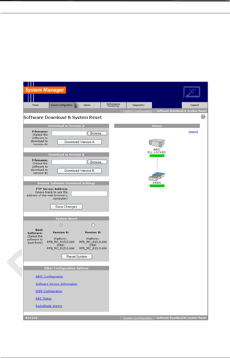
MC-Series ©2008 RadioFrame Networks, Inc. 6-9
Proprietary and Confidential Information
MC-Series Standard Capacity system998-1019-01 Rev X1
Note: Before starting the download in step 3 , be sure
to clear any FTP Server Address that shows up in
the Remote Software Download Settings field.
If you need to clear an address from this field, you
must click the Save Changes button.
Figure 6.9 Download and Reset Links

MC-Series Standard Capacity system 998-1019-01 Rev X1
6-10 ©2008 RadioFrame Networks, Inc. MC-Series
Proprietary and Confidential Information
Note: iDEN Cabinet/Sector Information is not preserved
in a downgrade from a 15.0 MCRB release to any
non-MCRB release. Care should be taken to
record this information and re-enter it as
necessary after a downgrade.
Note: In the following procedures, ffs0 is partition A;
ffs1 is partition B.
3. Using the inactive partition—“Download Version A” or “Download Version B” in
System Manager—navigate to the /platform/loads/MC-Series directory, and
then run the download on the following two files (observe the Download
Successful page; if a file fails, download it again):
• rom_staging.txt
• plat_staging.txt
The inactive partition is the one that is not selected under System Reset (A or
B). Browse for the file in the text box of the inactive partition, A or B, and then
select the Download to Version… button.
4. Using the inactive partition
a. “Download Version A” or “Download Version B” in System Manager.
b. Navigate to the /iden2/loads/BplusMC-Series directory.
c. Run the download on the following file (observe the Download
Successful page; if it fails, repeat the download):
• iden_staging.txt
a. Reboot the system using System Manager to the new load and wait for
the download to complete successfully, which may take several minutes.
This release must also be downloaded to the other partition at this time.
5. Using the inactive partition
a. “Download Version A” or “Download Version B” in System Manager.
b. Navigate to the /platform/loads/MC-Series directory.
c. Run the download on the following file (observe the Download
Successful page; if it fails, repeat the download):
• plat_staging.txt
6. Using the inactive partition
a. “Download Version A” or “Download Version B” in System Manage.
b. Navigate to the /iden2/loads/BplusMC-Series directory.
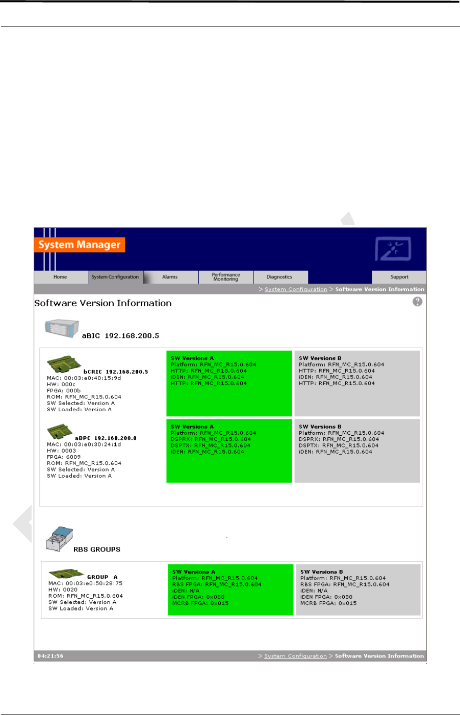
MC-Series ©2008 RadioFrame Networks, Inc. 6-11
Proprietary and Confidential Information
MC-Series Standard Capacity system998-1019-01 Rev X1
c. Run the download on the following file (observe the Download
Successful page; if it fails, repeat the download):
• iden_staging.txt
a. Reboot the system using System Manager to the new load and wait for
the download to complete successfully, which may take several minutes.
6.2.1 Verify the Software Download
1. Select the Software Version Information link on the System Configuration page.
Figure 6.10 Software Version Information Page

MC-Series Standard Capacity system 998-1019-01 Rev X1
6-12 ©2008 RadioFrame Networks, Inc. MC-Series
Proprietary and Confidential Information
2. Review the SW Versions A and SW Versions B to make sure the latest software
is loaded in the correct partition.
3. Verify that the SW Selected and SW Loaded for each component in the system
is correct.
6.3 Rollback to the previous version of software
Revert to a previous version of MCSC system software only if the upgrade fails.
1. Select the Software Download & System Reset link on the System
Configuration page.
2. On the Software Download & System Reset page (Figure 6.9), under System
Reset, select the inactive partition to revert to the previously loaded version of
software.
3. Select the Reset System button.
This reboot will take several minutes to complete. Wait for the system to come
back, and then refresh the page or reopen the web browser to force the page
to update.
6.4 Performing a System Reset
1. If necessary, connect the laptop to the MCSC system, start System Manager,
and log in (for complete instructions, refer to section 5.2 (System Setup)).
2. Select the Software Download & System Reset on the System Configuration
page.
3. On the Software Download & System Reset page (Figure 6.9), select the Reset
System button.
4. Follow the procedure in section 9.6 (Adding or Removing RadioBlade
Transceivers) to add or remove a RadioBlade transceiver.

MC-Series ©2008 RadioFrame Networks, Inc. 7-1
Proprietary and Confidential Information
MC-Series Standard Capacity system998-1019-01 Rev X1
Overview
The procedures in this chapter describe final checkout for each portion of
the MCSC system.
Contents
7.1 Final Checkout procedures...................................................................... 7-2
7.1.1 Prerequisites........................................................................................ 7-2
7.1.2 Checkout Procedures .......................................................................... 7-3
Chapter 7 Final Checkout

MC-Series Standard Capacity system 998-1019-01 Rev X1
7-2 ©2008 RadioFrame Networks, Inc. MC-Series
Proprietary and Confidential Information
7.1 Final Checkout procedures
This chapter describes procedures for:
• Prerequisites
• Checkout procedures
• Final checkout setup
• Initial power
• System setup
• System verification
• Functionality test
7.1.1 Prerequisites
Ensure that the following has taken place:
• The T1 is live and has been tested
• The datafill has been completed, including BR cabinet and position
assignments, and conforms to the recommended datafill shown in section
5.3.3 (Recommended Datafill Parameters).
• Site configuration is available
• All cabling and installation work has been completed and all punchlist items
corrected
Required Tools:
• R2660 Series Communication System Analyzer
• Digital RF meter
• Laptop computer to bring up the MCSC system. At a minimum, the laptop
must be loaded with the following fully functional equipment (or equivalent):
• Pentium II / 233 MHz (Pentium III / 500 MHz recommended, or better)
• 128 MB of memory (256 MB recommended)
• 10 GB hard drive (64 MB disk drive space minimum available for
software)
• 12x (or faster) CD-ROM (USB memory stick with 64 MB recommended)
• Windows 2000 Professional or better recommended
• Internet Explorer 6.0 or later (not Mozilla Firefox)
• One Ethernet port and one 9-pin serial port

MC-Series ©2008 RadioFrame Networks, Inc. 7-3
Proprietary and Confidential Information
MC-Series Standard Capacity system998-1019-01 Rev X1
• 6-foot Cat-5 (or 5e/6) Ethernet cable (EIA/TIA 568B) to connect to the ABIC
CRIC
• Straight-through, male-to-female serial cable (DB9/RS232)
• 50 ohm 2W terminating loads for all RF ports to be used according to the
site configuration
Ensure that the following RadioFrame Networks software is available:
• CD ROM (backup)
• New versions can also be downloaded from RadioFrame Networks web site
to the local root directory (C:/)
For local software downloads, have the following available on the laptop:
• FTP server software—WFTPD32 is shareware that can be downloaded
from the following site: http://www.wftpd.com/
• Terminal emulation software (e.g., PROCOM)
7.1.2 Checkout Procedures
1. Verify that all breakers in the PDU are in the OFF position prior to proceeding.
Leave them in the OFF position until instructed otherwise.
2. Conduct a visual inspection of the cabling on the rear of the cabinet verifying
that all connections are in place, tight, and complete.
3. Add and remove RadioBlade transceivers according to the site configuration.
Refer to section 9.7 (RadioBlade Transceiver Replacement).
4. Verify that cabling matches the site configuration.
5. Refer to Appendix C (MC-Series Standard Capacity system Cabling).
6. Install 50 ohm 2 W terminators on all unused Tx / Rx / Rx Diversity ports on the
rear of the enclosure.
7. Verify that there is DC power at the supply terminals on the PDU and that the
polarity is correct. Refer to section Chapter 2 (Specifications) for more
information.
Caution!
Verify that all breakers in the PDU are in the OFF position prior to proceeding.
Leave them in the OFF position until instructed otherwise.

MC-Series Standard Capacity system 998-1019-01 Rev X1
7-4 ©2008 RadioFrame Networks, Inc. MC-Series
Proprietary and Confidential Information

MC-Series ©2008 RadioFrame Networks, Inc. 8-1
Proprietary and Confidential Information
MC-Series Standard Capacity system998-1019-01 Rev X1
Overview
This chapter provides maintenance and troubleshooting guidelines fro the
MCSC system.
Contents
8.1 Maintenance............................................................................................ 8-2
8.1.1 Annual Maintenance............................................................................ 8-2
8.2 Troubleshooting Guidelines..................................................................... 8-2
8.3 Hardware Alerts....................................................................................... 8-3
8.3.1 Fault Indications................................................................................... 8-3
8.3.2 ABIC Indicators.................................................................................... 8-3
8.3.3 DRBS Indicators .................................................................................. 8-4
8.3.4 RF Shelf Indicators .............................................................................. 8-4
8.4 Software Alerts ........................................................................................ 8-5
System Manager Alarms ..................................................................... 8-5
8.4.1 Viewing System Manager Alarms........................................................ 8-5
8.4.2 OMC Alarm Code ................................................................................ 8-8
iDEN Alarm Code 4133 ....................................................................... 8-9
8.4.3 System Manager Alarms ................................................................... 8-10
8.5 RadioBlade Transceiver Alarm Handling................................................8-11
8.6 RadioBlade Troubleshooting ................................................................. 8-12
8.6.1 RadioBlade Locking Policy ................................................................ 8-12
8.6.2 Standby Blade.................................................................................... 8-12
8.6.3 Locking Policy for RadioBlade Transceiver with Errors ..................... 8-13
8.7 Serial Log Upload Procedure ................................................................ 8-15
Chapter 8 Troubleshooting the MC-Series Standard
Capacity system

MC-Series Standard Capacity system 998-1019-01 Rev X1
8-2 ©2008 RadioFrame Networks, Inc. MC-Series
Proprietary and Confidential Information
8.1 Maintenance
A report of the MCSC system should be maintained and left on site. This report will
provide metrics for possible concerns with individual components and/or the entire
system. It is important that the technician performing the checks understand the
equipment theory and operation. Review the documentation (references) prior to
verification and performing service.
For non-RadioFrame Networks hardware, refer to the equipment manufacturer’s
documentation for maintenance information and procedures. For the iSCIII and the
EAS, refer to the Gen 3 Site Controller System Manual, Motorola, 68P80801E30-O.
For the CSU, refer to the manufacturer's documentation for preventive maintenance
information.
8.1.1 Annual Maintenance
Conduct the following annual maintenance:
• Visually inspect all equipment in the MCSC system cabinet for loose or
foreign items and for visible damage.
• Verify site-configuration cabling is correct.
• Conduct the BER test on each RadioBlade transceiver. Refer to Appendix E
(BER Test Procedure).
• Conduct the TOR Tx measurement (RF output measurement) on each
transmitter.
8.2 Troubleshooting Guidelines
Technicians should conduct the following troubleshooting steps in order:
1. Visually inspect for fault indication (LEDs).
2. Inspect the Alarm Manager, and follow alarm resolution procedures. Refer to
the Alarm and Event Guide as well as sections 8.4 (Software Alerts) and 8.5
(RadioBlade Transceiver Alarm Handling) of this Implementation Guide.
3. Contact the RadioFrame Networks Technical Assistance Center at: (800) 328-
0847. Also, refer to section Appendix G (Repair and Technical Support).
4. Copy and save the serial log upload if directed; refer to section 8.7 (Serial Log
Upload Procedure).
5. Refer to sections 9.2 (Power Down Procedure) and 9.1 (Field Replaceable
Units (FRUs)) as necessary.

MC-Series ©2008 RadioFrame Networks, Inc. 8-3
Proprietary and Confidential Information
MC-Series Standard Capacity system998-1019-01 Rev X1
8.3 Hardware Alerts
8.3.1 Fault Indications
This section provides fault indications for the following RadioFrame Networks
components only: ABIC, DRBS and RF Shelf. For all non-RadioFrame Networks
equipment, refer to or the manufacturer’s documentation.
8.3.2 ABIC Indicators
Table 8.1 BIC LED Indications
LED Indication Condition Corrective action
POWER
green normal condition none
not lit no power to ABIC
• Verify that ABIC circuit breaker on PDU is
ON.
• Check power connection to PDU.
• Measure power input, and compare with
tolerances listed in Chapter 2
(Specifications).
• Verify that the power source is
operational.
• Contact the TAC: (800) 328-0847
STATUS
green normal condition none
not lit card(s) not receiving power • Verify power to ABIC (see “no power to
ABIC” above)
red
CRIC only
bootup not complete • Allow three minutes (approx.) for bootup
to complete.
timing not synchronized • Verify that the GPS LED on iSCIII is
green.
• Verify that the cable is connected from
ABIC ERTM port 5MHz/1PPS IN to iSCIII
port 5MHz/1PPS.
• Contact the TAC: (800) 328-0847
red
any card PLLs are not locked
• Verify that the STATUS LED on the ABIC
CRIC is green
• Check the Alarm Manager for PLL LOCK
alarm; wait 3 minutes for PLLs to lock; if
they do not:
• Verify integrity of the ABIC Ethernet
connection.
• Contact the TAC: (800) 328-0847
MC-Series Standard Capacity system 998-1019-01 Rev X1
8-4 ©2008 RadioFrame Networks, Inc. MC-Series
Proprietary and Confidential Information
8.3.3 DRBS Indicators
Table 8.2 DRBS LED Indications
8.3.4 RF Shelf Indicators
LED Indication Condition Corrective action
STATUS
green normal condition none
not lit no power to DRBS
• Verify that DRBS circuit breaker on
PDU is ON.
• Check power connection to PDU.
• Measure power input, and compare
with tolerances listed in section
Chapter 2 (Specifications),
• Verify that the power source is
operational.
• Contact the TAC: (800) 328-0847
red
timing is not synchronized to
the group (A, B, or C)
Board unable to boot
• Power cycle the DRBS using the
circuit breaker on the PDU.
• Contact the TAC: (800) 328-0847
RADIOBLADE
TRANSCEIVER
STATUS
green RadioBlade transceiver
present and operational none
not lit
RadioBlade transceiver not
present none
RadioBlade transceiver
present
• Reseat RadioBlade transceiver.
red RadioBlade transceiver is in
error state
• Reseat RadioBlade transceiver.
• If still red, replace RadioBlade
transceiver.

MC-Series ©2008 RadioFrame Networks, Inc. 8-5
Proprietary and Confidential Information
MC-Series Standard Capacity system998-1019-01 Rev X1
Table 8.3 RF Shelf LED Indications
8.4 Software Alerts
System Manager Alarms
The MCSC system provides fault alarming and isolation within System Manager for
individual components, which consists of detecting catastrophic faults that prevent a
component from responding to a periodic “ping”. Depending on the severity, alarms
are sent to the OMC via the iSCIII.
The Alarms/Events Reference Guide, included on the MC-Series CD and available
on the RadioFrame Networks website, lists the alarms by ID code.
All alarms passed to the OMC use the Alarm Code 35009, which uses the event
description “Unable to key BR”.
8.4.1 Viewing System Manager Alarms
1. Select the Alarms tab in System Manager to display the Active Alarm Manager.
The Alarm Log displays active (un-cleared) alarms listed by date and time, and
the Alarm Details window displays information about a single selected alarm
(see Figure 8.1). A summary at the top of the page lists the current number of
Critical, Major, Minor, and Warning alarms. Alarms that are no longer active are
moved to the Alarm History Manager.
LED Indication Condition Corrective action
POWER
green normal condition none
not lit no power to RF shelf
• Verify that RF circuit breaker on PDU is ON.
• Check power connection to PDU.
• Measure power input, and compare with
tolerances listed in section Chapter 2
(Specifications).
• Verify that the power source is operational.
• Contact the TAC: (800) 328-0847
ALARM
green normal condition •none
not lit not receiving power • Verify power to RF Shelf (see “POWER” above).
red alarm condition
• Check the Alarm Manager for:
RF SHELF MINOR, replace fan.
RF SHELF MAJOR, replace RF shelf.
• Contact the TAC: (800) 328-0847
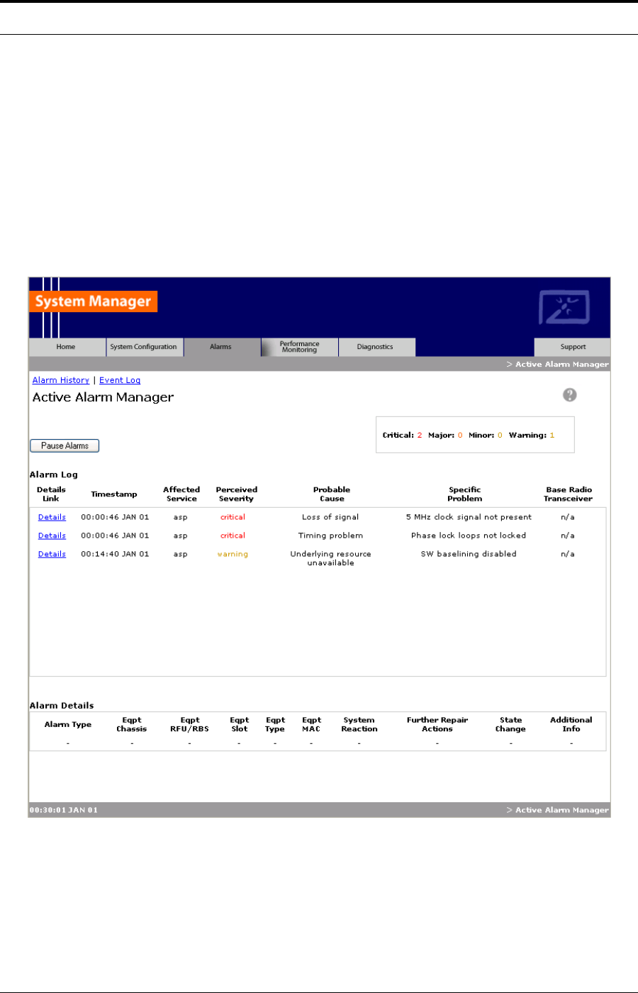
MC-Series Standard Capacity system 998-1019-01 Rev X1
8-6 ©2008 RadioFrame Networks, Inc. MC-Series
Proprietary and Confidential Information
Note: If the Alarms page is empty, System Manager is
still loading the page.
Non-alarm events are displayed in the Events Log. The initial Events Log lists
all the alarms generated by RFS components. You can view a smaller list by
selecting one of the Show links at the bottom of the page. Clicking the first link
with a value of 20 in the box displays the first 20 alarms. You can enter any
number in the field.
Figure 8.1 Alarm Log Page
MC-Series ©2008 RadioFrame Networks, Inc. 8-7
Proprietary and Confidential Information
MC-Series Standard Capacity system998-1019-01 Rev X1
Table 8.4 Alarm Log Fields
2. To view details about a specific alarm, select the Details link next to the alarm.
The Alarm Details window displays the information listed in Table 8.5.
Alarms Log Field Description
Details Displays details of the alarm in the Alarm Details window
Timestamp Date and time alarm occurred (in Greenwich meantime-GMT)
Affected Service iden: iDEN software only
asp: platform software only
RadioFrame Networks: All system software is affected (platform, iDEN)
Perceived Severity
cleared: A ‘set’ alarm has been cleared and moved to Alarm History
critical: Service affecting failure; requires immediate attention
major: Service affecting degradation; requires urgent attention
minor: Non-service affecting condition; requires scheduled attention
warning: Potential condition that may lead to a more serious alarm
Probable Cause Describes what might have caused the alarm
Specific Problem Describes the problem more specifically
Base RadioTransceiver BR ID (1 through 32) or n/a for not applicable
MC-Series Standard Capacity system 998-1019-01 Rev X1
8-8 ©2008 RadioFrame Networks, Inc. MC-Series
Proprietary and Confidential Information
Table 8.5 Alarm Details Fields
8.4.2 OMC Alarm Code
All RFS MC-Series alarms sent to the OMC use the Alarm Code 35009. Table 8.6
shows the properties for this alarm code. The Event Description for this alarm is
'Unable to key BR'.
Alarm Details Field Description
Alarm Type
Communication: failure to convey information
Quality of service: signal degradation
Processing error: software processing fault
Equipment: equipment fault
Environmental: condition with the equipment enclosure
Eqpt Chassis Affected chassis: ABIC
Eqpt Rfu/Rbs Affected DRBS group: grp A or grp C
Eqpt Slot Affected chassis slot: ABIC (1-5) or DRBS (1-24)
Eqpt Type
RadioFrame Networks: unknown
rlic: ABIC CRIC
bpc: BPC or BPC+SPAM
ric: ABIC CRIC
rbs: DRBS
idenrb: RadioBlade transceiver
Eqpt Mac MAC address of the affected component
System Reaction The action taken by the system as a result of the alarm
Further Repair Actions Corrective action that should be taken as a result of the alarm
State Change Not currently used (displays ‘false’ by default)
Additional Info Miscellaneous 32-bit field

MC-Series ©2008 RadioFrame Networks, Inc. 8-9
Proprietary and Confidential Information
MC-Series Standard Capacity system998-1019-01 Rev X1
Table 8.6 Alarm Code 35009 Properties
iDEN Alarm Code 4133
The Pole Mount system also introduces a new iDEN alarm (4133). Table 8.7
shows the properties for this alarm code.
In an MCSC system with greater than 6 carriers provisioned in a sector, the
default TX power cannot exceed 9.2. It is necessary, therefore, to reconfigure the
default TX power to a value of 9.2 or less.
If more than 6 carriers are provisioned in a single sector AND the defaultTxPower
exceeds 9.2 on any of those BRs, then the maximum allowable TX Power will be
de-rated for the BRs in that Sector as shown in Table 8.8.
Event Description
Alarm Code 35009
Event Type CntrlBrd
Alarm Type Equipment Failure
Actionable Yes
Severity Minor, Major or Critical
Bounce Threshold (x) 3
Bounce Threshold Minutes 30
Duration Threshold 10
Related Alarms None
R & C RC
Outage Y/N S1_El CY
Event Description Unable to key BR
Advisor Site Service call
Comments None
Alert Names BREFCTLBD35009
Last updated 8/3/2001
Revision
Change Notes
8/3/2001: per new EBTS rules baseline.
Changed severity and threshold from GR1 to:
Severity=minor
BounceThreshold=3
Bounce Threshold Minutes=30
Duration Threshold=10
Action Create trouble ticket.
Contact Field Technician.
TS/BR
MC-Series Standard Capacity system 998-1019-01 Rev X1
8-10 ©2008 RadioFrame Networks, Inc. MC-Series
Proprietary and Confidential Information
Table 8.7 Alarm Code 4133 Properties
Table 8.8 Maximum BR derated TxPower
8.4.3 System Manager Alarms
The document Alarms/Events Reference Guide lists MCSC system alarms
numerically by alarm ID (0x01, 0x02, etc.).
MC-Series alarms are based on the X.733 conventions for telecommunications
equipment. The alarms are grouped by service: either “asp” for platform faults or
“iden” for iden application faults. The “cause” field contains the X.733 cause type.
“System reaction” describes the action taken by the system as a result of this
alarm, and “repair actions” provides details on what corrective action should be
taken as a result of this alarm.
The Alarm details on the active alarm manager page of System Manager provides
additional information with respect to the board, slot number, MAC address and
equipment type.
Event Description
Alarm Code 4133
Event Type iDEN
Severity Major
Cause Configuration Customization Error.
System reaction Set the default TX power to 9.2.
Additional Info Session ID
Repair Action In a configuration where the number of carriers per sector
exceed six, the default TX power can’t exceed 9.2.
Reconfigure the default TX power to a value of 9.2 or less.
MC-
Series
Max # Of
Carriers/
Sector
Max Power Output per
Carrier @ 6 carriers with
defaultTxPower set to 9.5
New de-rated
Power at 9.2
Standard
Capacity 12 2W 1W
MC-Series ©2008 RadioFrame Networks, Inc. 8-11
Proprietary and Confidential Information
MC-Series Standard Capacity system998-1019-01 Rev X1
8.5 RadioBlade Transceiver Alarm Handling
The iDEN RadioBlade transceivers cabinet various faults and reports to the
RadioBlade controller. These faults are monitored, and if the rate at which these
faults occur surpasses a threshold, the RadioBlade transceiver (blade) is locked. The
blade will generate these faults as the result of normal actions such as re-syncing the
blade, locking and unlocking the blade and locking and unlocking the BR. For these
reasons, only if the blade continues to generate these faults under normal operating
circumstances is an alarm generated.
The RadioBlade transceiver faults are listed in Table 8.9.
Table 8.9 Faults by the Transceiver
If a RadioBlade transceiver generates enough errors such that it crosses the Bounce
and Duration threshold for that particular error, an alarm will be generated. This
alarm will also cause the RadioBlade Locking Policy to lock that RadioBlade
transceiver. Table 8.10 lists the fault count and fault period for an alarm to be
generated.
Fault Description
PLL1 Errors The Phase Lock Loop #1 went out of lock.
PLL2 Errors The Phase Lock Loop #2 went out of lock.
PLL3 Errors The Phase Lock Loop #3 went out of lock.
Tx Underrun RadioBlade transceiver did not receive a packet in time to transmit.
Tx Overflow RadioBlade transceiver received too many packets to transmit.
Rx OverFlow Sample buffer overflowed.
Slot mismatch Received packets were not consecutive.
CRC errors Received Ethernet packets had CRC errors.
MC-Series Standard Capacity system 998-1019-01 Rev X1
8-12 ©2008 RadioFrame Networks, Inc. MC-Series
Proprietary and Confidential Information
Table 8.10 RadioBlade Transceiver Fault Thresholds for Alarm Generation
8.6 RadioBlade Troubleshooting
In addition to the above-mentioned errors, if the system loses communication with a
RadioBlade transceiver or is unable to read the EEPROM from the blade, then that
blade is put into an error state and if a standby blade is available it will switch over
automatically.
8.6.1 RadioBlade Locking Policy
The RadioBlade locking policy defines the actions taken by the system when a
determination is made that a RadioBlade transceiver should no longer be allowed
to remain active. This could be the result of an alarm, insertion, removal or
intervention (the user specifically locking the RadioBlade transceiver).
In general, the policy is that if a blade is taken out of service and a standby
RadioBlade transceiver is available, then the standby RadioBlade transceiver will
go into service. If no standby RadioBlade transceiver is available then the
associated BR(s) will be locked. (For the Multi-Channel RadioBlade transceiver,
the locking event locks all carriers.)
The RadioBlade locking policy is enabled by default and in effect at all times.
8.6.2 Standby Blade
A Standby Blade is an extra RadioBlade transceiver that is installed in the system
but does not have a configured BR with which to register. To setup Standby
Blades, make sure that there are more RadioBlade transceivers for each DRBS
Group than Base Radios configured in the iDEN configuration page.
Alarm Bounce Threshold
(counts) Duration Threshold
(minutes)
PLL 1 75 12
PLL 2 75 12
PLL 3 50 12
Tx Underrun 40 12
Tx Overflow 40 12
Rx Overflow 40 12
Slot Mismatch 40 12
CRC Errors 20 12
Packet Size Errors 20 12

MC-Series ©2008 RadioFrame Networks, Inc. 8-13
Proprietary and Confidential Information
MC-Series Standard Capacity system998-1019-01 Rev X1
In all the conditions described below, if RadioBlade transceivers are present in the
system that are in the hot-standby state, then locking the RadioBlade transceiver
(due to alarms, removal of a RadioBlade transceiver or administratively locking
RadioBlade transceivers) will result in the hot Standby Blade transceiver being
assigned to the BR that de-registered the locked RadioBlade transceiver.
8.6.3 Locking Policy for RadioBlade Transceiver with Errors
If the RadioBlade transceiver generates enough faults such that it crosses the
Bounce and Duration threshold for that particular error, an alarm will be
generated. The RadioBlade controller then notifies the associated BR, which then
locks the RadioBlade transceiver. This will result in disabling the BR.
If there is a faulty RadioBlade transceiver in the system (generating error alarms),
it is prevented from coming up after a commanded reset/system reset, but the
operator could manually unlock the RadioBlade transceiver, at which point the
RadioBlade transceiver would be assigned to a BR. (This would not prevent the
system from locking it again if an excessive error condition recurs).
A. Removal of RadioBlade Transceiver
When a RadioBlade transceiver is physically removed, an event is generated
in the System Manager Event Log notifying the user about the RadioBlade
transceiver removal. The RadioBlade controller will then de-register the
RadioBlade transceiver from the BR(s), which will result in locking the BR(s).
A RadioBlade transceiver Insert event is generated when the RadioBlade
transceiver is inserted into the system.
B. Administrative Locking of a RadioBlade Transceiver
By definition, administrative locking of a RadioBlade transceiver is in effect if
the RadioBlade transceiver lock icon on the RadioBlade Transceiver Status
page is changed to “locked”.
The Multi-Channel RadioBlade transceiver is treated as a unit (single RBID)
with respect to administrative locking.
The following rules apply to locking a RadioBlade transceiver.
• The BR(s) associated with the administratively locked RadioBlade
transceiver will go into a Disabled state. Only that RadioBlade
transceiver will lock, and its icon will change to “locked”.
• If an administratively locked RadioBlade transceiver is replaced, the new
RadioBlade transceiver will be considered unlocked upon insertion.
(Administrative locking applies to a particular RadioBlade transceiver and
not to a particular DRBS Slot).

MC-Series Standard Capacity system 998-1019-01 Rev X1
8-14 ©2008 RadioFrame Networks, Inc. MC-Series
Proprietary and Confidential Information
• Upon unlocking an administratively locked RadioBlade transceiver, the
BR that was previously disabled due to the locked state will go into the
enabled state.
The lock policy will be preserved through a system reset. Locking of the
RadioBlade transceiver will also be preserved through a system reset. Locking
of RadioBlade transceivers in the disabled state will not be preserved through a
system reset. However, after a system reset, those blades that were originally
in the disabled state due to the effects of a) the locked RadioBlade transceiver
and b) the locking policy will likely return to the disabled state.
The RadioBlade Control page of System Manager has a “Lock All / Unlock All”
feature. Refer to Figure 8.2. With an MCRB, locking the top padlock as shown
on the RadioBlade Control page will lock all carriers for that MCRB while
selecting the padlock on the individual carrier will lock only that carrier.
MC-Series ©2008 RadioFrame Networks, Inc. 8-15
Proprietary and Confidential Information
MC-Series Standard Capacity system998-1019-01 Rev X1
Figure 8.2 System Lock All / Unlock All Feature
8.7 Serial Log Upload Procedure
Complete this procedure before disconnecting and removing the ABIC, DRBS or an
RF shelf from the MCSC system cabinet, or at the direction of RadioFrame Networks
technical support.
1. Select the Diagnostics tab in System Manager, and then select the Serial Log
Upload link.
MC-Series Standard Capacity system 998-1019-01 Rev X1
8-16 ©2008 RadioFrame Networks, Inc. MC-Series
Proprietary and Confidential Information
Figure 8.3 Serial Log Upload Link, Diagnostics Tab
2. Select the Upload Serial Log w/ IP Address button, and in the pop-up window,
enter the IP address of the component, and then select OK.
Alternately, the component can be selected from the drop-down menus, though
RadioFrame Networks recommends using the IP address method.
3. Copy the contents of the serial log window into a text file and save the text file.
4. Email the text file to the Technical Assistance Center at:
support@radioframenetworks.com

MC-Series ©2008 RadioFrame Networks, Inc. 9-1
Proprietary and Confidential Information
MC-Series Standard Capacity system998-1019-01 Rev X1
Overview
The MCSC system has been designed so that Field Replaceable Units
(FRUs) can be replaced to restore normal system operation as quickly as
possible. This chapter describes show to replace the FRU components.
Contents
9.1 Field Replaceable Units (FRUs) .............................................................. 9-2
9.1.1 Field Replaceable Unit (FRU) Policy ................................................... 9-2
9.1.2 Field Replaceable Units (FRUs), Parts and Extra Supplies................. 9-3
9.2 Power Down Procedure........................................................................... 9-3
9.3 RF Shelf................................................................................................... 9-5
9.3.1 RF Shelf Replacement Procedure....................................................... 9-5
9.3.2 Replacing a Fan in the RF Shelf.......................................................... 9-7
9.4 Replacing a Chassis: ABIC or DRBS ...................................................... 9-8
9.4.1 ABIC .................................................................................................... 9-8
9.4.2 DRBS................................................................................................. 9-10
9.5 ABIC– FRU Replacement Procedure .................................................... 9-12
9.5.1 Replacing the CRIC........................................................................... 9-12
9.5.2 BPC ................................................................................................... 9-14
9.5.3 ERTM................................................................................................. 9-16
9.5.4 CRTC................................................................................................. 9-18
9.6 Adding or Removing RadioBlade Transceivers..................................... 9-20
9.7 RadioBlade Transceiver Replacement .................................................. 9-20
9.8 Power Distribution Unit (PDU) ............................................................... 9-24
9.8.1 PDU ................................................................................................... 9-25
Chapter 9 Field Replaceable Unit (FRU) Procedures

MC-Series Standard Capacity system 998-1019-01 Rev X1
9-2 ©2008 RadioFrame Networks, Inc. MC-Series
Proprietary and Confidential Information
9.1 Field Replaceable Units (FRUs)
The MCSC system has been designed so that Field Replaceable Units (FRUs) can
be replaced to restore normal system operation as quickly as possible.
Refer to section Appendix G (Repair and Technical Support), Table 9.1, which lists
RadioFrame Networks FRUs. Do not attempt to repair RadioFrame Networks
equipment and components in the field. Be sure to read section 9.1.1 (Field
Replaceable Unit (FRU) Policy).
For support of RadioFrame Networks equipment, contact the RadioFrame Networks
Technical Assistance Center (TAC) at:
(US) 1-800-328-0847
For equipment not supplied by RadioFrame Networks, follow and procedures for
FRU replacement.
9.1.1 Field Replaceable Unit (FRU) Policy
The MCSC system has been designed so that Field Replaceable Units (FRUs)
can be replaced to restore normal system operation as quickly as possible.
RadioFrame Networks components are individually tested prior to shipment. If
RadioFrame Networks equipment should require service or repair, note the
following information, and then contact the RadioFrame Networks Technical
Assistance Center at (800) 328-0847:
Note: Do not attempt to repair RadioFrame Networks
equipment and components in the field.
Note: Always use a static grounding wrist strap before
handling any chassis or RadioBlade® transceiver.
• Include the serial numbers of the affected equipment.
• Give a clear return address, including:
• Securely package the FRU in its original shipping carton, if
available. Otherwise, package in a static protection bag in
a well-padded carton.
Table 9.1 lists current FRU equipment for the MCSC system. For equipment not
supplied by RadioFrame Networks, follow standard policies and procedures for
FRU replacement.

MC-Series ©2008 RadioFrame Networks, Inc. 9-3
Proprietary and Confidential Information
MC-Series Standard Capacity system998-1019-01 Rev X1
Table 9.1 FRU Table
9.1.2 Field Replaceable Units (FRUs), Parts and Extra Supplies
It is recommended that the spares for the MCSC system and maintain inventories
in Logistics Centers for ordering on an as-needed basis.
The MCSC system has been designed so that Field Replaceable Units (FRUs)
can be replaced to restore normal system operation as quickly as possible. Refer
to the previous section 9.1.1 and the FRU table, Table 9.1.
For equipment not supplied by RadioFrame Networks, such as the EAS, iSCIII, or
CSU, follow standard and procedures for FRU replacement.
Note: The previous section contains recommended part
numbers (P/N) and manufacturers of various
hardware, tools and equipment used during the
installation, operations and maintenance of the
MCSC system.
9.2 Power Down Procedure
When powering down the entire MCSC system, follow these instructions.
RadioFrame
Networks PM Description
176-0610-XX Power Distribution Unit (PDU)
176-1040-XX Airlink/BTS Interface Chassis (BIC)
176-7090-XX Rx Filter
176-1076-XX RF Shelf
176-1030-XX Diversity RadioBlade Transceiver Shelf (DRBS)
176-0180-XX Fan DRBS
176-1090-XX 800E Tx Filter
176-1223-01 Outdoor Pole Mount cabinet
176-1219-XX Fan Tray (w/fans) for an ABIC Chassis
176-0011-XX Fan for DRBS and RF Shelf
176-7555-XX Base Processing Card (BPC) w/(2) SPAM-HC
176-7540-XX MC Common RadioFrame Interface Card (CRIC)
176-7562-XX Ethernet Rear Transition Module (ERTM)
176-0820-CC Coaxial RMII Transceiver Card (CRTC)
176-7502-XX 4U Chassis
176-0860-XX MCRB iDEN FRU

MC-Series Standard Capacity system 998-1019-01 Rev X1
9-4 ©2008 RadioFrame Networks, Inc. MC-Series
Proprietary and Confidential Information
Using the breakers on the PDU, power off equipment in the MCSC system in the
following order:
1. ABIC
2. DRBS
3. RF Shelf 1
4. RF Shelf 2
5. RF Shelf 3
6. CSU
7. EAS
a. Ensure that the power switch on the front of the unit is in the OFF
position.
8. iSCIII 1
9. iSCIII 2
a. Ensure that the power switch on the front of the unit is in the OFF
position.
MC-Series ©2008 RadioFrame Networks, Inc. 9-5
Proprietary and Confidential Information
MC-Series Standard Capacity system998-1019-01 Rev X1
9.3 RF Shelf
Figure 9.1 RF Shelf Front and Rear View
9.3.1 RF Shelf Replacement Procedure
1. Power down RadioFrame Networks equipment in the following order using
circuit breakers on the PDU:
a. ABIC
b. DRBS
c. RF shelf 1
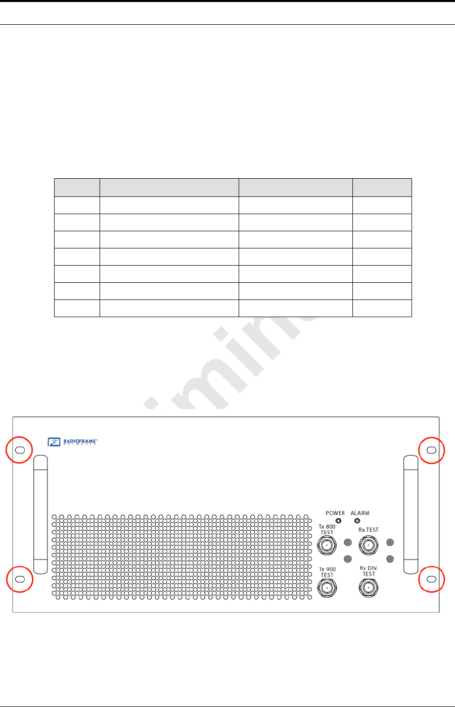
MC-Series Standard Capacity system 998-1019-01 Rev X1
9-6 ©2008 RadioFrame Networks, Inc. MC-Series
Proprietary and Confidential Information
d. RF shelf 2
e. RF shelf 3
2. Disconnect cabling from the back of the chassis to be replaced.
a. Disconnect the cabling from the rear of RF Shelf..)
Table 9.2 Cables to Disconnect from Rear of RF Shelf
3. Remove the four front mounting screws and remove the RF shelf from the
cabinet, and then package it for shipment.
Figure 9.2 RF Shelf Mounting Screw Locations
4. Mount the replacement RF shelf.
Index Disconnect From To Type
HRF Shelf x: power PDU: RF x power
ARF Shelf x: ground GND BAR ground
U-A RF Shelf x: Tx IN A DRBS 1: Tx A RF cable
S-A RF Shelf x: Rx OUT A DRBS 1: Rx A RF cable
LRF Shelf x: TX 800E OUT TOR: Tx 800E x RF cable
IRF Shelf x: RX 800E IN TOR: RF 800E x RF cable
TRF Shelf x: ALARM DRBS: ALARM INPUT A serial

MC-Series ©2008 RadioFrame Networks, Inc. 9-7
Proprietary and Confidential Information
MC-Series Standard Capacity system998-1019-01 Rev X1
While supporting the RF shelf, slide it into the cabinet mounting position.
Secure the RF shelf to the cabinet mounting rails using the four mounting
screws provided with the unit. Tighten the screws to 4.5 Nm (40 in-lb).
5. Reconnect the cabling to the replacement chassis.
Note: Use the SMA torque wrench for all SMA
connectors.
6. Using the breakers on the PDU, turn up the ABIC and DRBS and then verify
that the components are operational before proceeding.
7. Wait approximately 3 minutes for the following indicators:
DRBS:
• The STATUS LED for each group will turn green in this order: A, B, and
then C.
• The RADIOBLADE TRANSCEIVER STATUS LEDs will turn red and then
green for each present RadioBlade transceiver. If no RadioBlade
transceiver is present, the LED will not light. To verify the contents of the
DRBS, pull out the shelf (powering off is not required) and inspect the
RadioBlade transceivers and their respective status LEDs. Reinsert the
DRBS. To do this, press up on one side rail locking arm and press down
on the other side rail locking arm, and then push the unit into the cabinet.
For an illustration of the locking arms, refer to Figure 9.13.
BIC CRIC:
The POWER and STATUS LEDs will turn red and then green. All other ABIC
card LEDs will turn green.
8. Using the breaker on the PDU, turn up RF Shelf and verify that the RF shelf is
operational before proceeding. The POWER and ALARM LEDs on the front of
the RF Shelf will turn green.
9. Refer to sections 5.2 (System Setup) and Appendix C (Functionality Test
Procedures) for configuration and verification.
9.3.2 Replacing a Fan in the RF Shelf
1. Verify which fan has failed (look at each fan and determine which fan(s) are not
turning).
2. Disconnect power from the fan.
3. Unscrew the two Phillips screws shown in Figure Figure 9.3.
4. Slide out the fan tray by its flange.
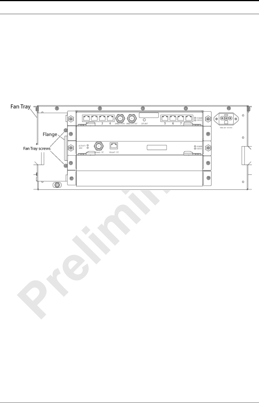
MC-Series Standard Capacity system 998-1019-01 Rev X1
9-8 ©2008 RadioFrame Networks, Inc. MC-Series
Proprietary and Confidential Information
5. Aligning the tabs on the bottom and top with the chassis, slide in the
replacement tray pushing firmly to seat the power connector.
6. Fasten the tray in place with the Phillips screws.
7. Tighten to 10 in/lbs using a hand or electric torque driver to ensure that vibration
does not loosen the tray.
Figure 9.3 Fan Mounting Screw Locations
8. Install the fan mounting screws.
9. Tighten to 10 in/lbs using a hand or electric torque driver to ensure that vibration
does not loosen the tray.
10. Install the finger guard so that the space is aligned vertically.
11. Connect the fan power cable.
12. Verify that the fan is working.
9.4 Replacing a Chassis: ABIC or DRBS
9.4.1 ABIC
1. Power down RadioFrame Networks equipment in the following order using
circuit breakers on the PDU:
• ABIC
• DRBS
• RF Shelf 1
• RF Shelf 2
• RF Shelf 3
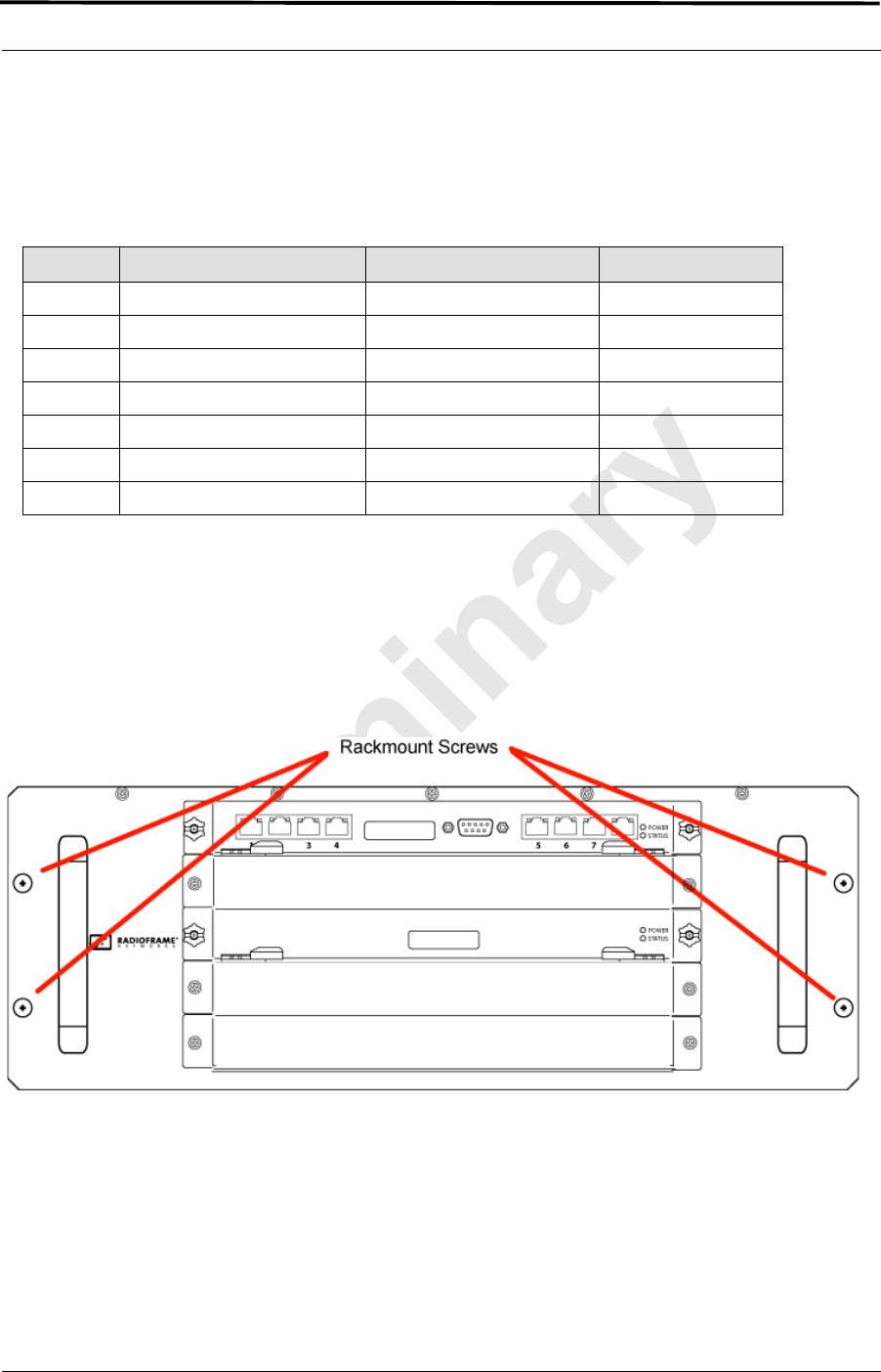
MC-Series ©2008 RadioFrame Networks, Inc. 9-9
Proprietary and Confidential Information
MC-Series Standard Capacity system998-1019-01 Rev X1
2. Disconnect cabling from the back of the chassis to be replaced.
Table 9.3 For the ABIC, disconnect the cabling (from the rear of the ABIC only) listed in Table
9.3.Cables to be Disconnected from the ABIC )
3. Remove the four front mounting screws from the front of the unit (see Figure
9.4).
4. Remove the chassis from the cabinet, and package it for shipment.
Figure 9.4 Front View of ABIC Showing Screw Locations
5. Mount the replacement chassis.
a. While supporting the chassis, slide the chassis into the cabinet
mounting position.
b. Secure the chassis to the cabinet mounting rails using the four mounting
screws provided with the unit.
c. Tighten the screws to 4.5 Nm (40 in-lb).
Index Disconnect From To Type
D ABIC: power PDU: ABIC power
A ABIC: ground GND BAR ground
I-1 ABIC: ERTM PORT 1 ABIC: CRTC 10baseT - ISC UTP
I-2 ABIC: ERTM PORT 2 ABIC: ERTM PORT 4 UTP
B ABIC: CRTC 10base2 - ISC ISC: 10B2-1 COAX (See Note)
C ABIC: CRTC 10baseT - ISC ABIC: ERTM PORT 1 UTP (See Note)
H ABIC: ERTM 5MHz/1PPS IN ISC: SITE REF OUT 1 COAX

MC-Series Standard Capacity system 998-1019-01 Rev X1
9-10 ©2008 RadioFrame Networks, Inc. MC-Series
Proprietary and Confidential Information
6. Reconnect the cabling to the replacement chassis as defined in Step 2 .
7. Using the breakers on the PDU, turn up the ABIC and DRBS and then verify
that the components are operational before proceeding.
a. Wait approximately 3 minutes for the following indicators:
DRBS:
• The STATUS LED for each group will turn green in this order: A, B, and
then C.
• The RADIOBLADE TRANSCEIVER STATUS LEDs will turn red and then
green for each present RadioBlade transceiver. If no RadioBlade
transceiver is present, the LED will not light. To verify the contents of the
DRBS, pull out the shelf (powering off is not required) and inspect the
RadioBlade transceivers and their respective status LEDs. Reinsert the
DRBS. To do this, press up on one side rail locking arm and press down
on the other side rail locking arm, and then push the unit into the cabinet.
For an illustration of the locking arms, refer to Figure 9.13.
BIC CRIC:
• The POWER and STATUS LEDs will turn red and then green. All other
ABIC card LEDs will turn green.
8. Using the breaker on the PDU, turn up the RF Shelf and then verify it is
operational before proceeding. The POWER and ALARM LEDs on the front of
the RF Shelf will turn green.
9. Complete the procedures in sections 5.2 (System Setup) and Appendix C
(Functionality Test Procedures).
9.4.2 DRBS
1. Power down RadioFrame Networks equipment in the following order using
circuit breakers on the PDU:
•BIC
• DRBS
• RF Shelf 1
• RF Shelf 2
• RF Shelf 3
2. Disconnect cabling from the back of the DRBS to be replaced.
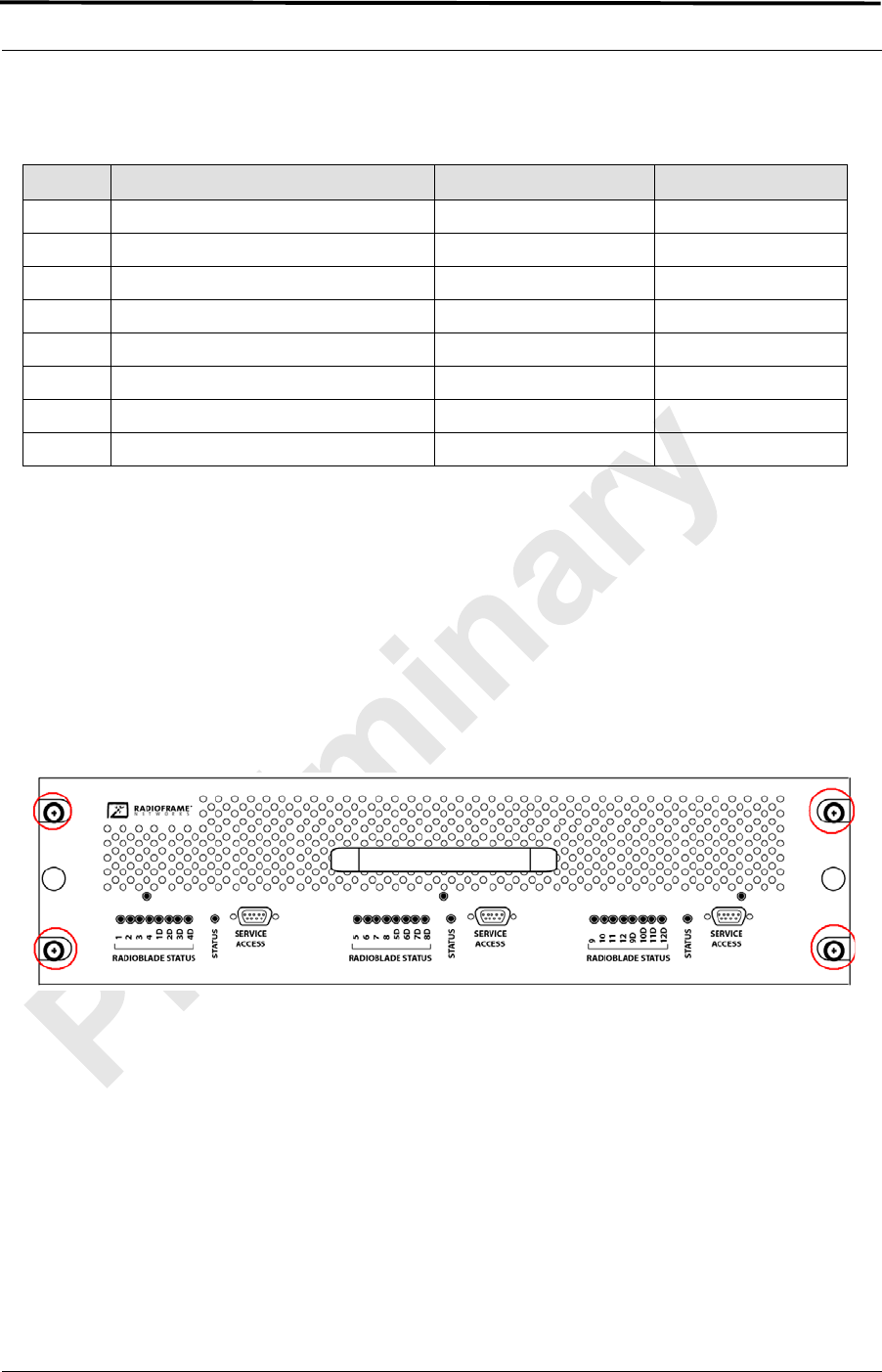
MC-Series ©2008 RadioFrame Networks, Inc. 9-11
Proprietary and Confidential Information
MC-Series Standard Capacity system998-1019-01 Rev X1
Table 9.4 Cables to be Disconnected from the Front of DRBS
Note: The serial alarm cable (RF Shelf x ALARM to
DRBS ALARM INPUT x) is not used with the
MCSC system. These cables may or may not be
present.
3. Remove the 4 front mounting screws (see Figure 9.5), remove the chassis from
the cabinet, and then package it for shipment.
Figure 9.5 Front View of DRBS Showing Mounting Screws
4. Mount the replacement chassis.
a. While supporting the chassis, slide the chassis into the cabinet
mounting position.
b. Secure the chassis to the cabinet mounting rails using the four mounting
screws provided with the unit.
c. Tighten the screws to 4.5 Nm (40 in-lb).
5. Reconnect the cabling to the replacement chassis as defined in Step 2 .
Index Disconnect From To Type
E DRBS: power PDU: DRBS 1 power
A DRBS: ground GND BAR ground
N DRBS: Tx A RF Shelf: Tx IN A RF cable
M DRBS: Rx A RF Shelf: Rx OUT A RF cable
K DRBS: ALARM INPUT A RF Shelf: ALARM serial (See Note)
J DRBS: 10/100 RadioFrame Networks A BIC: ERTM PORT 1 UTP
F DRBS: 10/100 RadioFrame Networks B BIC: ERTM PORT 2 UTP
B DRBS: 10/100 RadioFrame Networks C BIC: ERTM PORT 3 UTP

MC-Series Standard Capacity system 998-1019-01 Rev X1
9-12 ©2008 RadioFrame Networks, Inc. MC-Series
Proprietary and Confidential Information
Note: Use the SMA torque wrench for all SMA
connectors.
6. Using the breakers on the PDU, turn up the ABIC and DRBS and then verify
that the components are operational before proceeding.
a. Wait approximately 3 minutes for the following indicators:
DRBS:
• The STATUS LED for each group will turn green in this order: A, B, and
then C.
• The RADIOBLADE TRANSCEIVER STATUS LEDs will turn red and then
green for each present RadioBlade transceiver. If no RadioBlade
transceiver is present, the LED will not light. To verify the contents of the
DRBS, pull out the shelf (powering off is not required) and inspect the
RadioBlade transceivers and their respective status LEDs. Reinsert the
DRBS. To do this, press up on one side rail locking arm and press down
on the other side rail locking arm, and then push the unit into the cabinet.
For an illustration of the locking arms, refer to Figure 9.13.
ABIC CRIC:
• The POWER and STATUS LEDs will turn red and then green. All other
ABIC card LEDs will turn green.
7. Using the breaker on the PDU, turn up each RF Shelf and then verify that each
RF Shelf is operational before proceeding.
The POWER and ALARM LEDs on the front of the RF Shelf will turn green.
8. Complete the procedures in sections 5.2 (System Setup) and Appendix C
(Functionality Test Procedures).
9.5 ABIC– FRU Replacement Procedure
9.5.1 Replacing the CRIC
1. Before replacing any card (board) in the ABIC, power down RadioFrame
Networks equipment in the following order using circuit breakers on the PDU:
•BIC
IMPORTANT
BEFORE REPLACING ANY CARD (board) in the ABIC, power down the
RadioFrame Networks equipment in the following order using circuit breakers on
the PDU:
•BIC
• DRBS
•RF Shelf
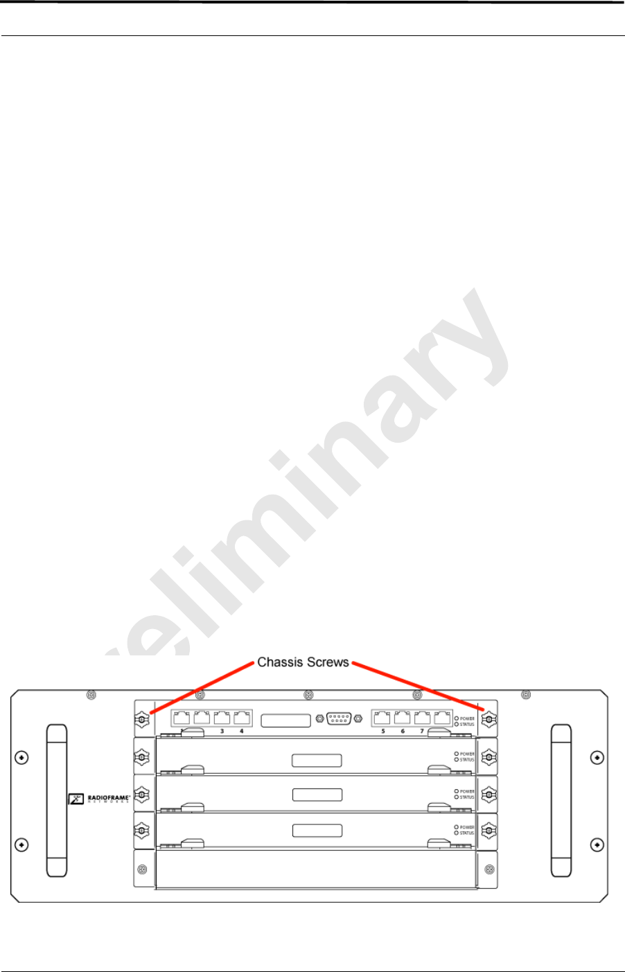
MC-Series ©2008 RadioFrame Networks, Inc. 9-13
Proprietary and Confidential Information
MC-Series Standard Capacity system998-1019-01 Rev X1
• DRBS
• RF Shelf
2. Always use a static grounding wrist strap before handling any board—do not
attach the wrist strap to any painted surface on the chassis unit.
3. Facing the ABIC, remove the CRIC that is to be replaced, following these
guidelines:
a. Loosen the blue knurled knobs on both sides of the board.
b. Pull firmly on the tabs located on the bottom of the CRIC.
c. Gently slide the CRIC straight out and away from the chassis unit so as
not to damage any components contained on the board.
4. Remove the replacement CRIC from its antistatic packaging and insert it into
the chassis unit as shown in Figure 9.6, and follow these guidelines:
a. Do not jam the board in any way while inserting it.
b. Do not mount the board in any orientation other than that specified in the
diagram.
c. Insert the board straight into the chassis unit so as not to damage any
components contained on the board.
d. Press firmly to seat the board into the connectors within the chassis unit.
e. Tighten the blue knurled knobs on each end of the board finger tight
only—do not use a screwdriver to tighten the screws and do not over
tighten.
Figure 9.6 Replacing the CRIC

MC-Series Standard Capacity system 998-1019-01 Rev X1
9-14 ©2008 RadioFrame Networks, Inc. MC-Series
Proprietary and Confidential Information
5. Place the old board in the antistatic packaging for shipment.
6. Using the breakers on the PDU, turn up the ABIC and DRBS and then verify
that the components are operational before proceeding.
a. Wait approximately 3 minutes for the following indicators:
DRBS:
• The STATUS LED for each group will turn green in this order: A and then
B, and finally C.
Note: Group “B” LED will only turn green if a second
sector (in the expansion cabinet (not covered in
this document)) has been configured.
Note: Group “C” LED will only turn green if a third
sector (in the expansion cabinet (not covered in
this document)) has been configured.
• The RADIOBLADE TRANSCEIVER STATUS LEDs will turn red and then
green for each present RadioBlade transceiver. If no RadioBlade
transceiver is present, the LED will not light. To verify the contents of the
DRBS, pull out the shelf (powering off is not required) and inspect the
RadioBlade transceivers and their respective status LEDs. Reinsert the
DRBS. To do this, press up on one side rail locking arm and press down
on the other side rail locking arm, and then push the unit into the cabinet.
For an illustration of the locking arms, refer to Figure 9.13.
ABIC CRIC
• The POWER and STATUS LEDs will turn red and then green. All other
ABIC card LEDs will turn green.
7. Using the breaker on the PDU, turn up each RF Shelf and then verify that each
RF Shelf is operational before proceeding.
The POWER and ALARM LEDs on the front of the RF Shelf will turn green.
8. FOR THE ABIC CRIC ONLY: complete the procedures in sections 5.2 (System
Setup) and Appendix C (Functionality Test Procedures).
9.5.2 BPC
1. Before replacing any card (board) in the ABIC, power down RadioFrame
Networks equipment in the following order using circuit breakers on the PDU:
•BIC
• DRBS
• RF Shelves
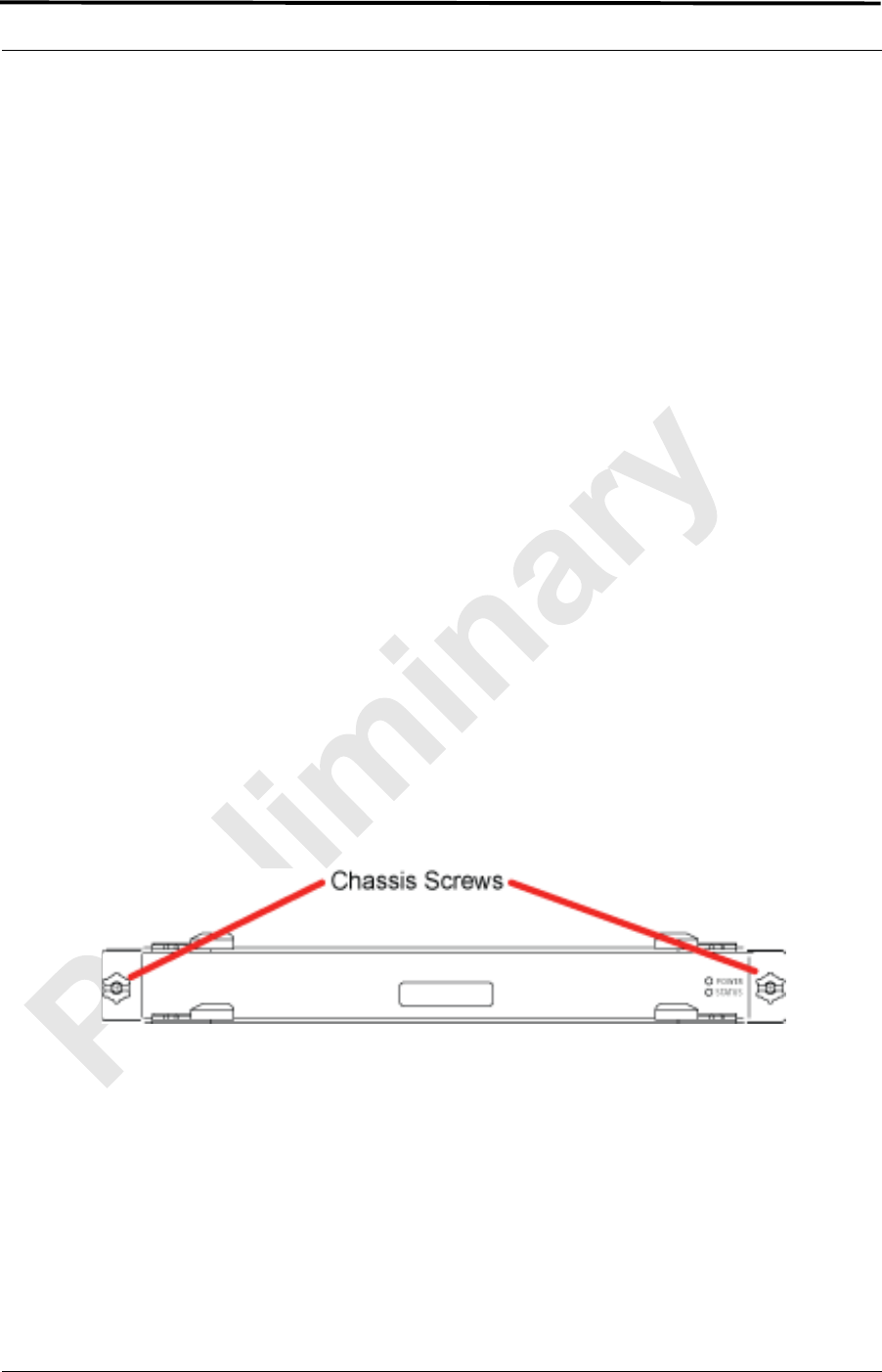
MC-Series ©2008 RadioFrame Networks, Inc. 9-15
Proprietary and Confidential Information
MC-Series Standard Capacity system998-1019-01 Rev X1
2. Always use a static grounding wrist strap before handling any board—do not
attach the wrist strap to any painted surface on the chassis unit.
3. Facing the chassis unit, remove the BPC that is to be replaced, or the blank
faceplate, following these guidelines:
a. Loosen the blue knurled knobs on both sides of the board.
b. Pull firmly on the tabs located on the bottom of the BPC you are
replacing.
c. Gently slide the BPC straight out and away from the chassis unit so as
not to damage any components contained on the board.
4. Remove the BPC from its antistatic packaging and insert it into the chassis unit
as shown in Figure 9.7, and follow these guidelines:
a. Do not jam the board in any way while inserting it.
b. Do not mount the board in any orientation other than that specified in the
diagram.
c. Insert the board straight into the chassis unit so as not to damage any
components contained on the board.
d. Press firmly to seat the board into the connectors within the chassis unit.
e. Tighten the blue knurled knobs on each end of the board finger tight
only—do not use a screwdriver to tighten the screws and do not over
tighten.
Figure 9.7 Replacing the BPC
5. Place the old board in the antistatic packaging for shipment.
6. Using the breakers on the PDU, turn up the ABIC and DRBS and then verify
that the components are operational before proceeding.
a. Wait approximately 3 minutes for the following indicators:

MC-Series Standard Capacity system 998-1019-01 Rev X1
9-16 ©2008 RadioFrame Networks, Inc. MC-Series
Proprietary and Confidential Information
DRBS:
• The STATUS LED for each group will turn green in this order: A, B, and
then C.
• The RADIOBLADE TRANSCEIVER STATUS LEDs will turn red and then
green for each present RadioBlade transceiver. If no RadioBlade
transceiver is present, the LED will not light. To verify the contents of the
DRBS, pull out the shelf (powering off is not required) and inspect the
RadioBlade transceivers and their respective status LEDs. Reinsert the
DRBS. To do this, press up on one side rail locking arm and press down
on the other side rail locking arm, and then push the unit into the cabinet.
For an illustration of the locking arms, refer to Figure 9.13.
ABIC CRIC
• The POWER and STATUS LEDs will turn red and then green. All other
ABIC card LEDs will turn green.
7. Using the breaker on the PDU, turn up the RF Shelf and then verify it is
operational before proceeding.
Note: The POWER and ALARM LEDs on the front of
the RF Shelf will turn green.
9.5.3 ERTM
1. Before replacing any card (board) in the ABIC, power down RadioFrame
Networks equipment in the following order using circuit breakers on the PDU:
•BIC
• DRBS
• RF Shelf 1
• RF Shelf 2
• RF Shelf 3
2. Always use a static grounding wrist strap before handling any board—do not
attach the wrist strap to any painted surface on the chassis unit.
3. Facing the rear of the ABIC, remove the ERTM that is to be replaced following
these guidelines:
a. Loosen the blue knurled knobs on both sides of the board.
b. Pull firmly on the tabs located on the bottom of the ERTM you are
replacing.
c. Gently slide the ERTM straight out and away from the chassis unit so as
not to damage any components contained on the board.
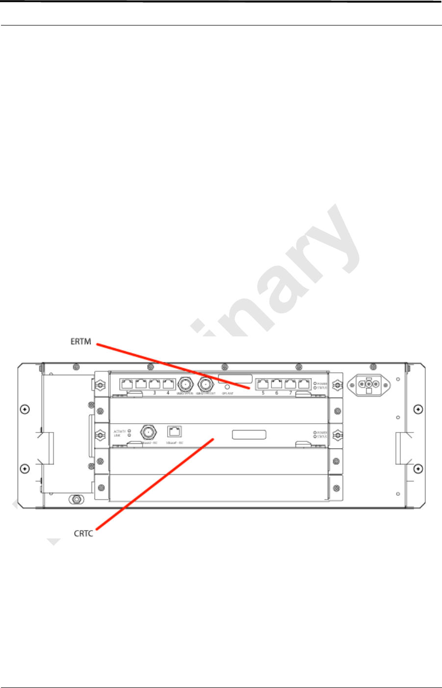
MC-Series ©2008 RadioFrame Networks, Inc. 9-17
Proprietary and Confidential Information
MC-Series Standard Capacity system998-1019-01 Rev X1
4. Remove the ERTM from its antistatic packaging and insert it into the chassis
unit as shown in 67, and follow these guidelines:
a. Check that the ERTM switch is in the correct position for the application.
The switch is located on the components side of the ERTM circuit board,
near the connector labeled “POWER”. Appropriate settings are:
A—for ERTM inserted in ABIC
b. Do not jam the board in any way while inserting it.
c. Do not mount the board in any orientation other than that specified in the
diagram.
d. Insert the board straight into the chassis unit so as not to damage any
components contained on the board.
e. Press firmly to seat the board into the connectors within the chassis unit.
f. Tighten the blue knurled knobs on each end of the board finger tight
only—do not use a screwdriver to tighten the screws and do not over
tighten.
Figure 9.8 Rear of ABIC (ERTM and CRTC)
5. Place the old board in the antistatic packaging for shipment.
6. Using the breakers on the PDU, turn up the ABIC and DRBS and then verify
that the components are operational before proceeding.
a. Wait approximately 3 minutes for the following indicators:

MC-Series Standard Capacity system 998-1019-01 Rev X1
9-18 ©2008 RadioFrame Networks, Inc. MC-Series
Proprietary and Confidential Information
DRBS:
• The STATUS LED for each group will turn green in this order: A, B,and
then C.
• The RADIOBLADE TRANSCEIVER STATUS LEDs will turn red and then
green for each present RadioBlade transceiver. If no RadioBlade
transceiver is present, the LED will not light. To verify the contents of the
DRBS, pull out the shelf (powering off is not required) and inspect the
RadioBlade transceivers and their respective status LEDs. Reinsert the
DRBS. To do this, press up on one side rail locking arm and press down
on the other side rail locking arm, and then push the unit into the cabinet.
For an illustration of the locking arms, refer to Figure 9.13.
ABIC CRIC
• The POWER and STATUS LEDs will turn red and then green. All other
ABIC card LEDs will turn green.
7. Using the breaker on the PDU, turn up the RF Shelf and then verify it is
operational before proceeding.
Note: The POWER and ALARM LEDs on the front of
the RF Shelf will turn green.
9.5.4 CRTC
1. Before replacing any card (board) in the ABIC, power down RadioFrame
Networks equipment in the following order using circuit breakers on the PDU:
•BIC
• DRBS
• RF Shelf 1
• RF Shelf 2
• RF Shelf 3
2. Always use a static grounding wrist strap before handling any board—do not
attach the wrist strap to any painted surface on the chassis unit.
3. Facing the rear of the ABIC, remove the CRTC following these guidelines:
a. Loosen the blue knurled knobs on both sides of the board.
b. Pull firmly on the tabs located on the bottom of the CRTC.
c. Gently slide the CRTC straight out and away from the chassis unit so as
not to damage any components contained on the board.
4. Remove the CRTC from its antistatic packaging and insert it into the chassis
unit as shown in Figure 9.8, and follow these guidelines:

MC-Series ©2008 RadioFrame Networks, Inc. 9-19
Proprietary and Confidential Information
MC-Series Standard Capacity system998-1019-01 Rev X1
a. Do not jam the board in any way while inserting it.
b. Do not mount the board in any orientation other than that specified in the
diagram.
c. Insert the board straight into the chassis unit so as not to damage any
components contained on the board.
d. Press firmly to seat the board into the connectors within the chassis unit.
e. Tighten the blue knurled knobs on each end of the board finger tight
only—do not use a screwdriver to tighten the screws and do not over
tighten.
5. Place the old board in the antistatic packaging for shipment.
6. Using the breakers on the PDU, turn up the ABIC and DRBS and then verify
that the components are operational before proceeding.
a. Wait approximately 3 minutes for the following indicators:
DRBS:
• The STATUS LED for each group will turn green in this order: A, B, and
then C.
• The RADIOBLADE TRANSCEIVER STATUS LEDs will turn red and then
green for each present RadioBlade transceiver. If no RadioBlade
transceiver is present, the LED will not light. To verify the contents of the
DRBS, pull out the shelf (powering off is not required) and inspect the
RadioBlade transceivers and their respective status LEDs. Reinsert the
DRBS. To do this, press up on one side rail locking arm and press down
on the other side rail locking arm, and then push the unit into the cabinet.
For an illustration of the locking arms, refer to Figure 9.13.
ABIC CRIC:
• The POWER and STATUS LEDs will turn red and then green. All other
ABIC card LEDs will turn green.
7. Using the breaker on the PDU, turn up each RF Shelf and then verify that each
RF Shelf is operational before proceeding.
Note: The POWER and ALARM LEDs on the front of
the RF Shelf will turn green.
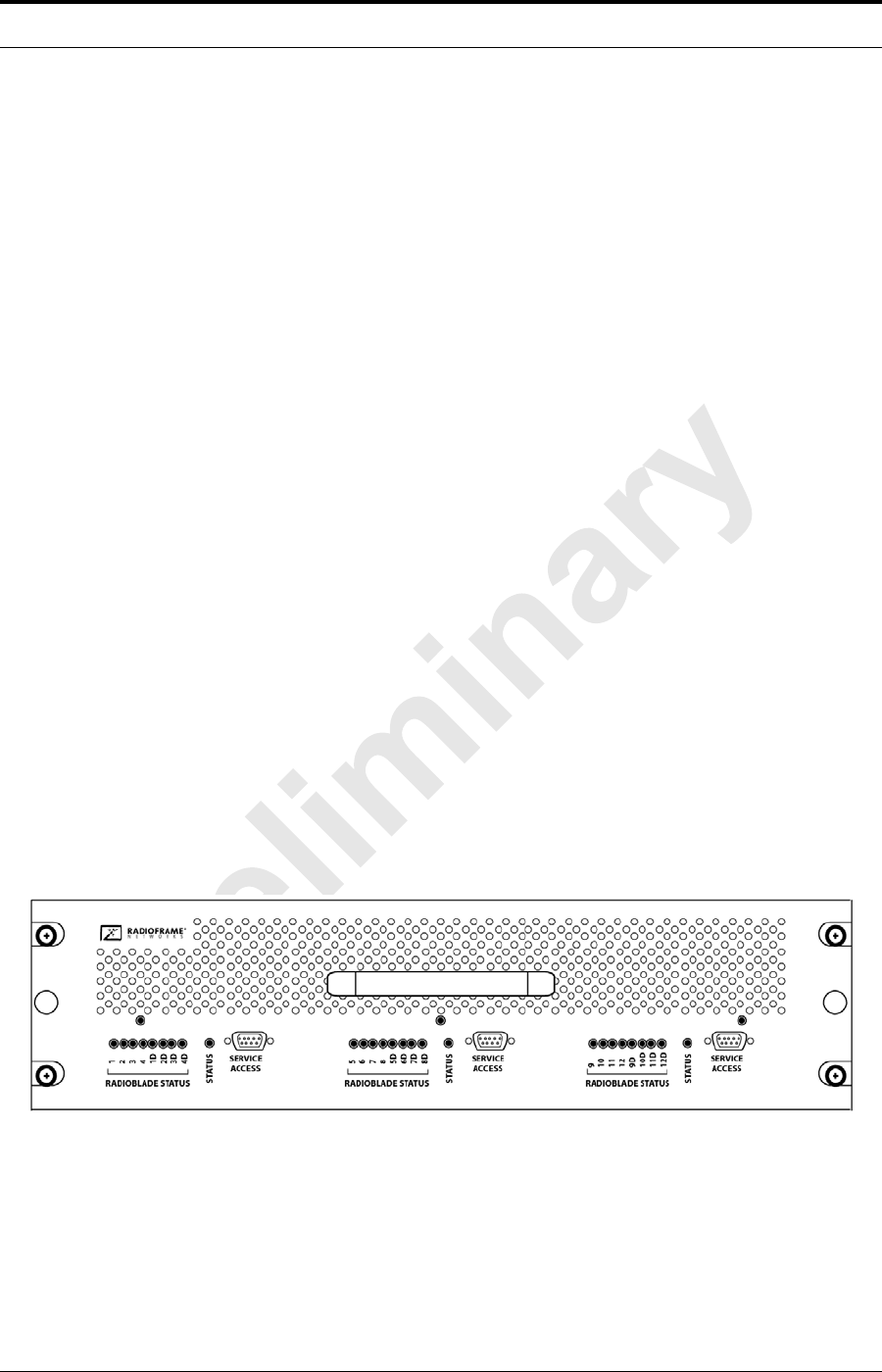
MC-Series Standard Capacity system 998-1019-01 Rev X1
9-20 ©2008 RadioFrame Networks, Inc. MC-Series
Proprietary and Confidential Information
9.6 Adding or Removing RadioBlade Transceivers
The MCSC system supports hot swapping of RadioBlade transceivers. This means
that replacement of a RadioBlade transceiver can be done while the system is live
and does not require a system reset. When RadioBlade transceivers are hot
swapped no alarm is generated. Rather, a RadioBlade transceiver lock and unlock
event is placed in the System Manager Event log.
Each RadioBlade transceiver is shipped wrapped in antistatic packaging, along with
a lock-down strap and screw for securing the RadioBlade transceiver in the
RadioBlade Shelf (DRBS).
Follow the procedure in Section 9.7 (RadioBlade Transceiver Replacement) to add or
remove a RadioBlade transceiver.
9.7 RadioBlade Transceiver Replacement
The MCSC system supports hot swapping of RadioBlade transceivers. This means
replacement of a RadioBlade transceiver can be done while the system is live and
does not require a system reset. When RadioBlade transceivers are hot swapped, no
alarm is generated. Rather, a RadioBlade transceiver lock / unlock event is placed in
the System-Manager Event Log.
Each RadioBlade transceiver is shipped wrapped in antistatic packaging, along with
a lock-down strap and screw for securing the RadioBlade transceiver in the
RadioBlade Shelf (DRBS).
Note: Use an SMA torque wrench (such as the Huber &
Suhner 742-0-0-21 SMA torque wrench) for
removing and installing RadioBlade transceivers.
Figure 9.9 Front View of the Diversity RadioBlade Shelf (DRBS)
1. Take the RadioBlade transceiver out of service by locking it (refer to the
procedure in section B. (Locking and Unlocking a RadioBlade Transceiver)).
The DRBS is comprised of two groups (A and C) from left to right. Slots in each
group are numbered as follows, from front to back:
• Group A: slots 1 through 8
MC-Series ©2008 RadioFrame Networks, Inc. 9-21
Proprietary and Confidential Information
MC-Series Standard Capacity system998-1019-01 Rev X1
• Group B: slots 9 through 16
• Group C: slots 17 through 24
Figure 9.10 DRBS Slot Group Arrangement
2. Pull out the DRBS using the handle on the front of the unit.
3. Remove the RadioBlade transceiver that is to be replaced.
a. Using the SMA torque wrench, disconnect the Rx and Tx cables from
the RadioBlade transceiver.
b. Loosen the screw of the lock-down strap covering the RadioBlade
transceiver, and remove the strap and screw and place them aside.
MC-Series Standard Capacity system 998-1019-01 Rev X1
9-22 ©2008 RadioFrame Networks, Inc. MC-Series
Proprietary and Confidential Information
c. Gently lift and remove the RadioBlade transceiver from the slot in the
DRBS backplane.
d. Place the RadioBlade transceiver in anti-static packaging for shipment.
Figure 9.11 RadioBlade Transceiver in Place
4. Install the replacement RadioBlade.
a. Un-package the replacement RadioBlade transceiver to be inserted into
the DRBS.
b. Insert the RadioBlade transceiver into the specified slot in the DRBS
until the connector seats firmly into the backplane of the DRBS.
c. Connect the Rx cable to the Rx port (the BOTTOM connector on the
MCRB) and Tx cable to the Tx port (the TOP connector) on the MCRB.
d. Place the lock-down strap over the RadioBlade transceiver by inserting
the two feet on the strap into the slots on the DRBS backplane, and then
hand tighten the screw into place.
Important:
Verify the connections are correct! Tx is the TOP connector on the MCRB; Rx is
the BOTTOM connector on the MCRB.
MC-Series ©2008 RadioFrame Networks, Inc. 9-23
Proprietary and Confidential Information
MC-Series Standard Capacity system998-1019-01 Rev X1
Figure 9.12 Seating the RadioBlade Transceiver
5. Connect the Rx and Tx cables to the correct ports on the RadioBlade
transceiver, and use the SMA torque wrench to tighten.
6. Re-insert the DRBS into its chassis. To do this, press up on one side rail locking
arm and press down on the other side-rail locking arm, and then push the unit
into the cabinet (see Figure 9.13).
MC-Series Standard Capacity system 998-1019-01 Rev X1
9-24 ©2008 RadioFrame Networks, Inc. MC-Series
Proprietary and Confidential Information
Figure 9.13 RF Shelf Showing Side-Rail Locking Arm Locations
Note: This image shows the default Main enclosure,
single sector configuration with the Group “A”
RadioBlade transceivers installed, Group “B”
location (RadioBlade transceivers not installed)
with the cover plate in place, and Group “C”
(RadioBlade transceivers not installed) with the
cover plate removed.
7. In System Manager, refresh the DRBS Status page until the RadioBlade
transceiver icon status bar changes from red (not present) to yellow (present
and locked). This will take approximately three minutes.
8. Unlock the RadioBlade transceiver.
Note: On the RadioBlade Transceiver Control page, the
State of the RadioBlade transceiver will change
from 2 (locked) to 11 (unlocked).
9.8 Power Distribution Unit (PDU)
The Power Distribution Unit (PDU) receives DC input and supplies power via
dedicated circuit breakers to each component in the MCSC system.
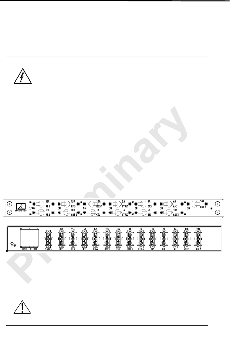
MC-Series ©2008 RadioFrame Networks, Inc. 9-25
Proprietary and Confidential Information
MC-Series Standard Capacity system998-1019-01 Rev X1
Each of the thirteen breakers has a three-position switch: ON, OFF or TRIPPED. The
single alarm output connected to each breaker is normally closed and goes open
when a breaker is tripped.
1. Verify that all breakers are in the OFF position on the front of the PDU.
2. Follow the power supply and battery manufacturer's installation and
maintenance documentation to remove power from the PDU.
3. Disconnect the powerplant from the PDU using the two lugs.
4. Remove all power connections from the back of the PDU.
5. Remove the 4 front mounting screws from the front of the PDU, and remove the
PDU from the cabinet, and then package it for shipment.
Figure 9.14 PDU Front and Rear View
9.8.1 PDU
1. Replace the PDU component.
a. While supporting the PDU, slide it into the cabinet mounting position.
Warning!
Verify that all breakers in the PDU are in the OFF position prior to proceeding.
Leave them in the OFF position until instructed otherwise.
Important
Before replacing the PDU verify the component is disconnected from the
powerplant.

MC-Series Standard Capacity system 998-1019-01 Rev X1
9-26 ©2008 RadioFrame Networks, Inc. MC-Series
Proprietary and Confidential Information
a. Secure the PDU to the cabinet mounting rails using the four mounting
screws provided with the unit.
b. Tighten the screws to 4.5 Nm (40 in-lb).
2. Reconnect all power connections to the back of the PDU.
3. Follow Power supply and battery manufacturer's installation and maintenance
documentation to install power to PDU.
4. Using the breakers on the PDU, turn up the ABIC and DRBS and verify that the
components are operational before proceeding.
a. Wait approximately 3 minutes for the following indicators:
DRBS:
• The STATUS LED for each group will turn green in this order: A, B, and
then C.
• The RADIOBLADE TRANSCEIVER STATUS LEDs will turn red and then
green for each present RadioBlade transceiver. If no RadioBlade
transceiver is present, the LED will not light. To verify the contents of the
DRBS, pull out the shelf (powering off is not required) and inspect the
RadioBlade transceivers and their respective status LEDs. Reinsert the
DRBS. To do this, press up on one side rail locking arm and press down
on the other side rail locking arm, and then push the unit into the cabinet.
For an illustration of the locking arms, refer to Figure 9.13.
ABIC CRIC
• The POWER and STATUS LEDs will turn red and then green. All other
ABIC card LEDs will turn green.
5. Using the breaker on the PDU, turn up each RF Shelf and then verify that each
RF Shelf is operational before proceeding. The POWER and ALARM LEDs on
the front of the RF Shelf will turn green.
6. Complete the procedures in sections 5.2 (System Setup) and Appendix C
(Functionality Test Procedures).

MC-Series Standard Capacity system
998-1019-01 Rev X1
MC-Series ©2008 RadioFrame Networks, Inc. A-1
Proprietary and Confidential Information
Appendix A General Safety Information
A.1 Static Sensitive Precautions
Electrostatic discharge (ESD) can damage equipment and impair electrical circuitry.
It occurs when electronic printed circuit cards are improperly handled and can result
in complete or intermittent failures.
• Prior to handling, shipping, and servicing equipment, always put on a
conductive wrist strap connected to a grounding device to discharge any
accumulated static charges. All RadioFrame Networks FRUs ship with a
disposable anti-static wrist strap.
• Place FRUs only on an anti-static mat when removed from the system. The
conductive surface must be connected to ground through 100 k.
• Do not use non-conductive material for packaging FRUs for shipment or
storage. Wrap all FRUs with anti-static (conductive) material. Replacement
FRUs shipped from the factory are packaged in a conductive material.
• If possible, retain all original packing material for future use.
Warning!
Use extreme caution when wearing a conductive wrist strap near sources of high
voltage. The low impedance provided by the wrist strap also increases the danger
of lethal shock should accidental contact with high voltage sources occur.
MC-Series Standard Capacity system 998-1019-01 Rev X1
A-2 ©2008 RadioFrame Networks, Inc. MC-Series
Proprietary and Confidential Information
A.2 Safety Warnings
A.3 Safety Warnings per Cabinet mount Instructions
The following or similar cabinet mount instructions are included with the installation
instructions:
Reduced Air Flow
Installation of the equipment in the cabinet should be such that the amount of air
flow required for safe operation of the equipment is not compromised.
Warning!
Use extreme caution when wearing a conductive wrist strap near sources of high
voltage. The low impedance provided by the wrist strap also increases the danger
of lethal shock should accidental contact with high voltage sources occur.
Warning!
Ultimate disposal of this product should be handled according to all national laws
and regulations.
Warning!
The user is cautioned that changes or modifications made to the equipment that
are not expressly approved by the party responsible for compliance, could void
the user’s authority to operate the equipment.
Warning!
To ensure FCC compliance of this equipment, it is the user’s responsibility
to obtain and use only shielded and grounded interface cables.
Warning!
FCC RF Exposure Compliance: FCC RF exposure compliance must be
addressed at the time of licensing, as required by the responsible FCC Bureau(s),
including antenna co-location requirements of §1.1307(b)(3). The applicable
exposure limits, to demonstrate compliance, are specified in FCC Part 1.1310.
Additionally, the installer of the antenna to be used with this transmitter may be
required to perform an MPE evaluation and an Environmental Assessment (EA) of
the location at the time of licensing per CFR 47 Part 1.1307. Fixed mounted
antenna(s) that are co-located with other antenna(s) must satisfy the co-location
requirements of Part 1.1307 for satisfying RF exposure compliance

MC-Series ©2008 RadioFrame Networks, Inc. A-3
Proprietary and Confidential Information
MC-Series Standard Capacity system
998-1019-01 Rev X1
Mechanical Loading
Mounting of the equipment in the cabinet should be such that a hazardous
condition is not achieved due to uneven mechanical loading.
Circuit Overloading
Consideration should be given to the connection of the equipment to the supply
circuit and the effect that overloading of the circuits might have on overcurrent
protection and supply wiring. Appropriate consideration of equipment nameplate
ratings should be used when addressing this concern.
Reliable Earthing
Reliable earthing of cabinet-mounted equipment should be maintained. Particular
attention should be given to supply connections other than direct connections to
the branch circuit (e.g., use of power strips).
A.4 Overall Recommendations
• Do not work alone if potentially hazardous conditions exist.
• Never assume that power is disconnected from a circuit. Always check.
• Look carefully for possible hazards in the work area, such as moist floors,
ungrounded extension cables, frayed power cords and missing safety grounds.

MC-Series Standard Capacity system 998-1019-01 Rev X1
A-4 ©2008 RadioFrame Networks, Inc. MC-Series
Proprietary and Confidential Information
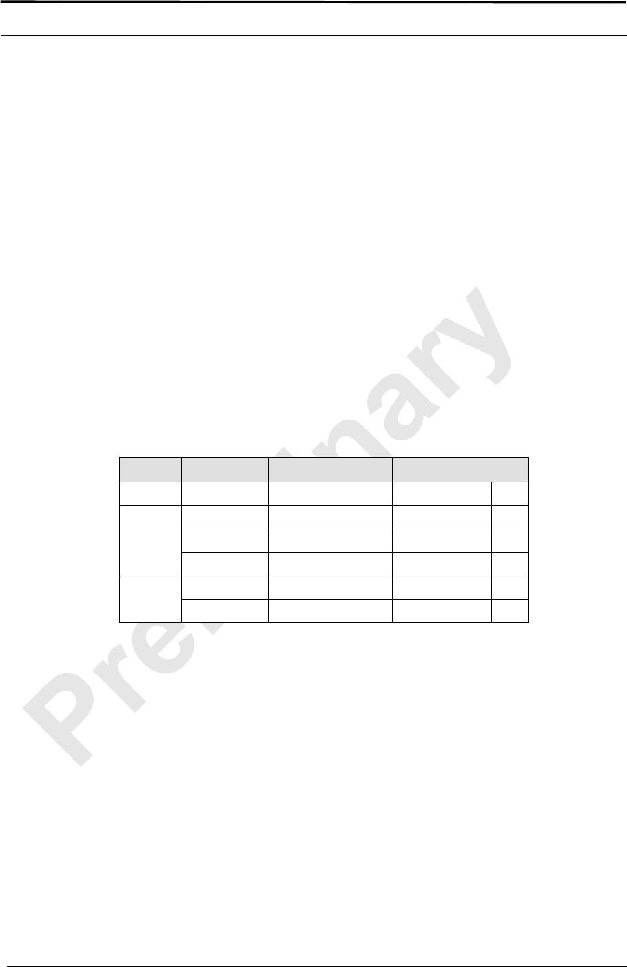
MC-Series Standard Capacity system
998-1019-01 Rev X1
MC-Series ©2008 RadioFrame Networks, Inc. B-1
Proprietary and Confidential Information
Appendix B IP Address Requirements
B.1 IP Address Requirements
The following table lists default IP addresses for RadioFrame Networks chassis
boards, and the default IP address required for logging in to the MCSC system.
Table B.1 Address and Port Numbers for Chassis Boards
Note: There is only one BPC installed at the time of
shipping. Additional BPCs are only installed if
configuring for a 2- or 3-sector site.
Device Card Type Chassis Slot/Port IP Address
Laptop N/A port 8 192.168.200. 253
ABIC
CRIC Slot 0 192.168.200. 5
BPC Slot 1 192.168.200. 6
BPC Slot 2 (See Note) 192.168.200. 7
DRBS backplane Group 1 192.168.200. 98
backplane Group 3 192.168.200. 100

MC-Series Standard Capacity system 998-1019-01 Rev X1
B-2 ©2008 RadioFrame Networks, Inc. MC-Series
Proprietary and Confidential Information

MC-Series Standard Capacity system
998-1019-01 Rev X1
MC-Series ©2008 RadioFrame Networks, Inc. C-1
Proprietary and Confidential Information
Appendix C Functionality Test Procedures
C.1 Interconnect and Dispatch Setup and Voice Quality Testing
Interconnect and Dispatch voice quality will be assessed by evaluating voice links as
described in (Table C.1), (Table C.2) and (Table C.3). RSSI and SQE measurements
will be made via the handset. These tests are to be performed on a selected sample
set of links.
MC-Series Standard Capacity system 998-1019-01 Rev X1
C-2 ©2008 RadioFrame Networks, Inc. MC-Series
Proprietary and Confidential Information
Table C.1 Interconnect Call Quality, Setup and Stability
Table C.2 Group Dispatch Call Quality, Setup and Stability
Test # MO/PSTN Carrier # RSSI
(dBm) SQE
(dBm) Quality
(1-5) Sector Duration
(Min)
1 2
2 2
3 2
4 2
5 2
PSTN/MT
1 2
2 2
3 2
4 2
5 2
MO/MT
1 2
2 2
3 2
4 2
5 2
Test # MO/MT Carrier # RSSI
(dBm) SQE
(dBm) Quality
(1-5) Sector Duration
(Min)
1 2
2 2
3 2
4 2
5 2
6 2
7 2
8 2
9 2
10 2
MC-Series ©2008 RadioFrame Networks, Inc. C-3
Proprietary and Confidential Information
MC-Series Standard Capacity system
998-1019-01 Rev X1
Table C.3 Private Dispatch Call Quality, Setup and Stability
C.2 Packet Data Service Connection and Latency
The Packet Data service will be tested and verified on the MCSC system. Motorola's
Packet Data Applet (laptop) will be used to connect to Packet Data network over the
MCSC system, using a tethered connection with a Motorola handset.
Several samples of PING requests will be sent to a router in Packet Data network
and average round trip times will be recorded to measure latency. (Table C.4)
presents the data to be collected for each ping using the MCSC system. These tests
shall be performed using Windows 2000 OS, and the timeout for each ping reply
shall be set to 2000 milliseconds.
Table C.4 Packet Data Latency MCSC system (Ping –n 100 –w 2000 xx.xxx.xxx.x)
Test # MO/
MT Carrier # RSSI
(dBm) SQE
(dBm) Quality
(1-5) Sector Duration
(Min)
12:30
22:30
32:30
42:30
52:30
62:30
72:30
82:30
92:30
10 2:30
Test
#Handset Carrier
#RSSI
(dBm) SQE
(dBm)
Ping
(No.
Echoes)
Router
(IP Address)
Avg.
Round-Trip
Time
(mSec)
Packet
Loss
(%)
1 100 xxx.xxx.xxx.x
2 100 xxx.xxx.xxx.x
3 100 xxx.xxx.xxx.x
4 100 xxx.xxx.xxx.x
5 100 xxx.xxx.xxx.x
MC-Series Standard Capacity system 998-1019-01 Rev X1
C-4 ©2008 RadioFrame Networks, Inc. MC-Series
Proprietary and Confidential Information
(Table C.5) presents (baseline) data collected for each ping using a Motorola Macrocell
in order to average Round Trip time over the MCSC system versus over Motorola
standard Base Station equipment.
Table C.5 Packet Data Latency over Motorola EBTS
C.3 Short Message Service
The Short Message Service (SMS) will be tested and verified by initiating the
delivery of a voice mail notification to the handset via one of the iDEN RadioBlade
transceiver links.
1. Navigate on a network connection to the Internet.
2. Enter the URL for the network operator in the web browser.
3. On the home page, in the “Send a Text Message” box near the bottom, enter
the 10-digit Nextel phone number of the test phone. The browser will display the
mobile messaging page.
4. Enter a short text message into the field for message, and also enter a subject
in the subject line.
5. Press the Send button. The message should appear on the test phone within a
few minutes.
C.4 Handover and Cell Reselection
Handover and Cell Reselection verifies that mobiles on the MCSC system
successfully handoff to the macro-cellular network during an interconnect call.
These tests also verify that mobiles on the MCSC system perform successful cell
reselection when in an idle state. (Table C.6) presents the data to be collected for
the handover and reselection tests.
Test
#Handset Carrier
#RSSI
(dBm) SQE
(dBm)
Ping
(No.
Echoes)
Router
(IP Address)
Average
Round-Trip
Time
(mSec)
Packet
Loss
(%)
1 100 xxx.xxx.xxx.x 0
2 100 xxx.xxx.xxx.x 0
3 100 xxx.xxx.xxx.x 0
4 100 xxx.xxx.xxx.x 0
5 100 xxx.xxx.xxx.x 0
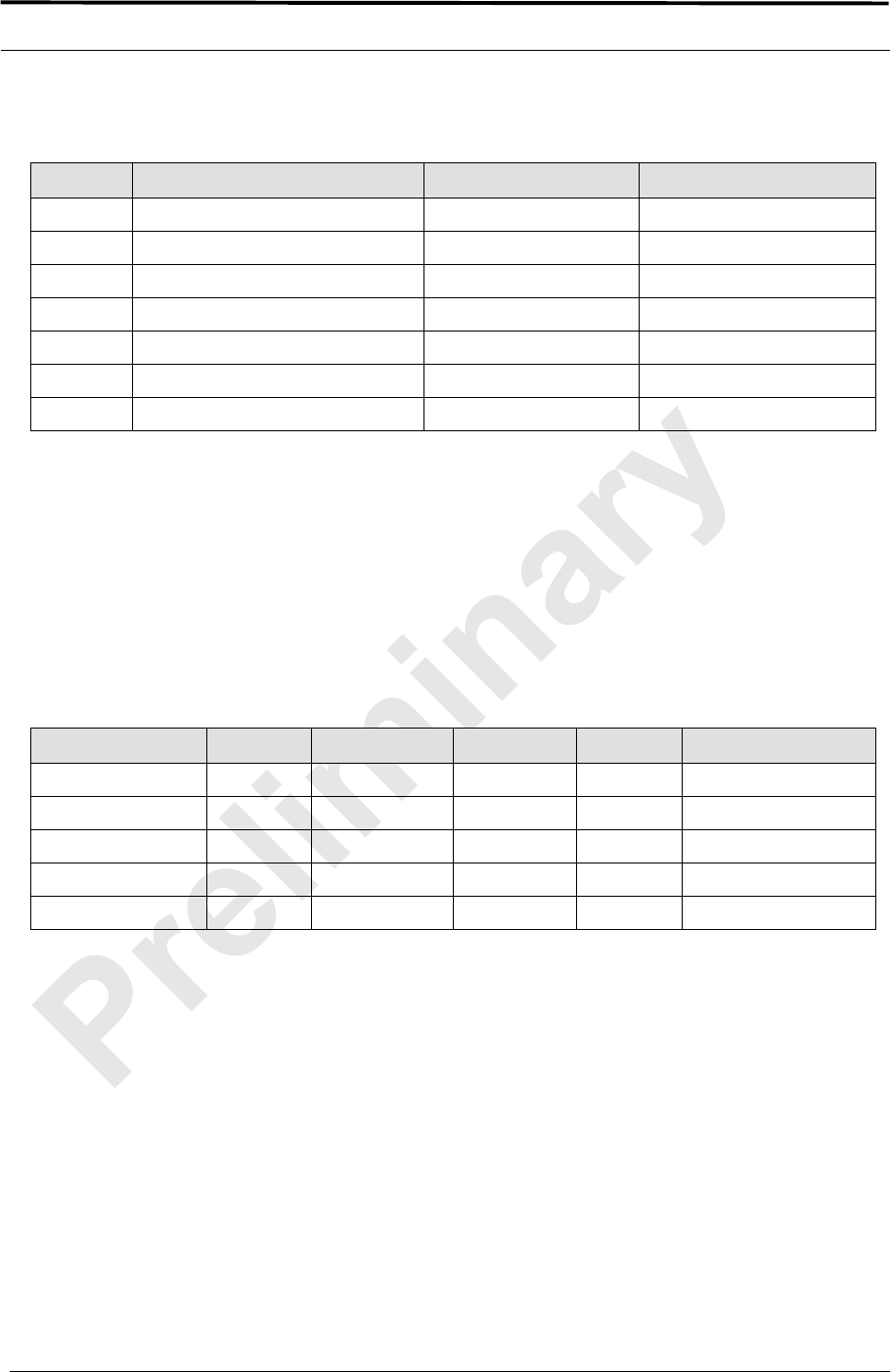
MC-Series ©2008 RadioFrame Networks, Inc. C-5
Proprietary and Confidential Information
MC-Series Standard Capacity system
998-1019-01 Rev X1
Table C.6 Handover and Reselection Test Worksheet
C.5 Interconnect Connection Stability and SQE Performance
A single link for 3:1 Interconnect should be maintained for 30 minutes each. (Table
C.7) presents the data to be collected for each selected link. The iDEN Field Test
Application (IFTA) is be used in “Single Cell” mode to observe the SQE performance
and plotted over time.
Table C.7 Interconnect Connection Stability Worksheet
C.6 Dispatch Connection Stability
To verify Dispatch connection stability, a Dispatch (private or group) call should be
maintained for several minutes. (Table C.8) presents the data to be collected for
each dispatch call.
Test # Handover (Mobile #) Carrier # from (HEX) Carrier # to (HEX)
1
2
3
Cell Reselection (Mobile #)
1
2
3
Interconnect #1 Carrier # RSSI (dBm) SQE (dB) Sector Duration (min)
30
Interconnect #2
30
Interconnect #3

MC-Series Standard Capacity system 998-1019-01 Rev X1
C-6 ©2008 RadioFrame Networks, Inc. MC-Series
Proprietary and Confidential Information
Table C.8 Dispatch Connection Stability Worksheet
C.7 Idle SQE Testing and Validation
Using the iFTA tool in “Single Cell” mode, record the idle RSSI and SQE values for
the control channel for at least one hour per sector, while the mobile remains fixed.
C.8 System Self-Recovery Test
The following test is to determine the ability of the MCSC system to recover from
various iSCIII conditions.
Loss of T1
While the MCSC system is operating, disconnect the T1/E1 connection to the
iSCIII for one minute, and then reconnect it. Monitor the system recovery, and
then validate the system by placing a successful call on each sector.
iSCIII Power Loss
While the MCSC system is operating, the iSCIII shall be power cycled and
system recovery will be monitored and validated by placing a successful call
on each sector.
Loss of GPS
While the MCSC system is operating, the GPS connection to the iSCIII will be
disconnected until all Satellites are lost and then reconnected. System
recovery will be monitored and validated by placing a successful call on each
sector.
New datafill download
System recovery will be verified by pushing a new datafill download to the
iSCIII.
Dispatch #1 Carrier # RSSI (dB) SQE (dB) Sector Quality (1-5) Duration (min)
3
Dispatch #2
4
Dispatch #3
5
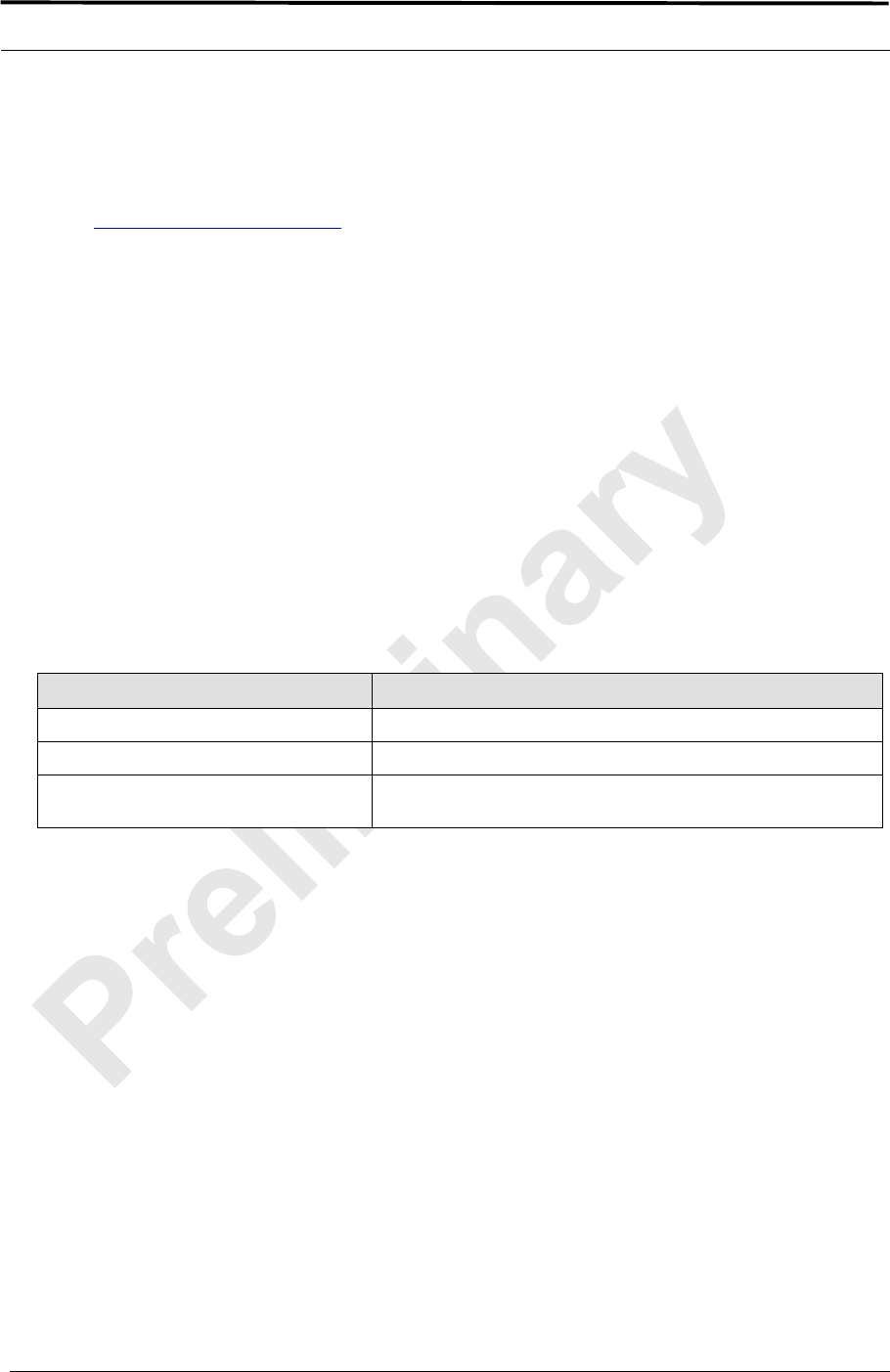
MC-Series ©2008 RadioFrame Networks, Inc. C-7
Proprietary and Confidential Information
MC-Series Standard Capacity system
998-1019-01 Rev X1
C.9 Packet Data Stability and Throughput
The Packet Data stability and throughput to the Internet will be verified. A tethered
Packet Data connection will be set up on a laptop and speed tested by using the
www.bandwidthplace.com website. This continuous download of data stream will
validate system stability and help to quantify user experience of Packet Data over
the MCSC system.
C.10 Validation of 'Unable to Key BR' Alarm
While the MCSC system is operating, disconnect any system component, from the
ABIC to the DRBS, and monitor the OMC to verify that MCSC system generates the
“Unable to Key BR” alarm.
The MCSC system provides fault alarming and isolation within System Manager for
individual components, which consists of detecting catastrophic faults that prevent
an MCSC system component from responding to a periodic “ping”. All fault alarms
generated by the MCSC system are received at the OMC via the iSCIII. The “Unable
to Key BR” alarm will appear at the OMC as minor, major or critical as follows (for
more information about alarms, refer to section 5.2 (System Setup) ):
Table C.9 “Unable to Key BR” Alarm Severity Indications
“Unable to Key BR” Alarm Severity Indication
minor An iDEN RadioBlade transceiver has failed.
major An RF Shelf has failed.
critical A card in a chassis unit has failed (except for the ABIC CRIC,
which is responsible for returning the alarm information.)

MC-Series Standard Capacity system 998-1019-01 Rev X1
C-8 ©2008 RadioFrame Networks, Inc. MC-Series
Proprietary and Confidential Information

MC-Series Standard Capacity system
998-1019-01 Rev X1
MC-Series ©2008 RadioFrame Networks, Inc. D-1
Proprietary and Confidential Information
Appendix D Tx / Rx Curves
D.1 800E Tx Filter Response
The 800E MHz Tx filter frequency response is shown below.
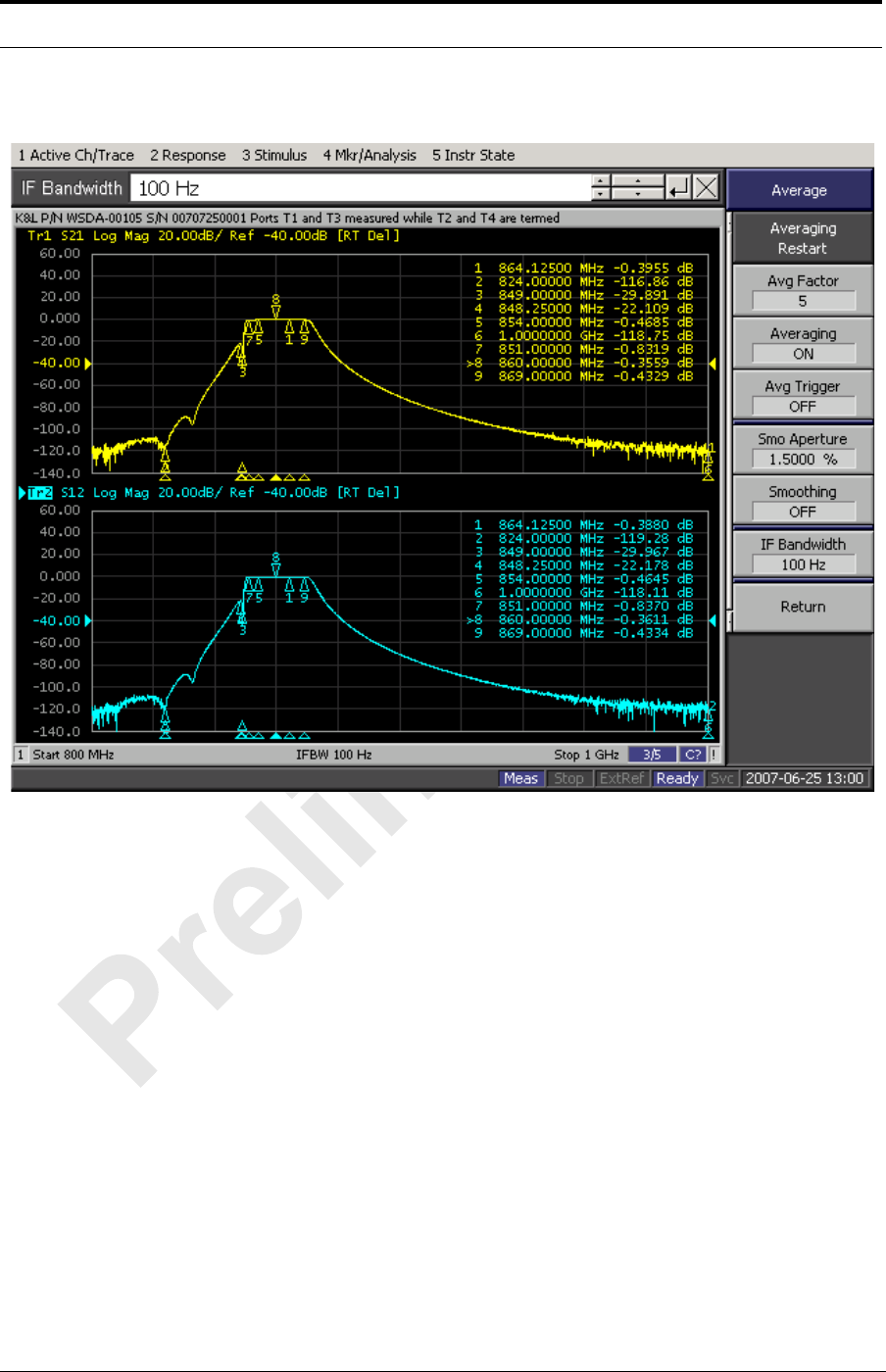
MC-Series Standard Capacity system 998-1019-01 Rev X1
D-2 ©2008 RadioFrame Networks, Inc. MC-Series
Proprietary and Confidential Information
Figure D-1 800E Band Transmit Filter Frequency Response
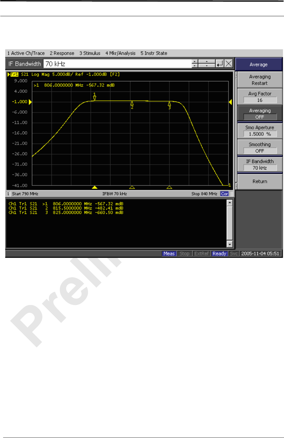
MC-Series ©2008 RadioFrame Networks, Inc. D-3
Proprietary and Confidential Information
MC-Series Standard Capacity system
998-1019-01 Rev X1
Figure D-2 800E Band Rx Filter Response

MC-Series Standard Capacity system 998-1019-01 Rev X1
D-4 ©2008 RadioFrame Networks, Inc. MC-Series
Proprietary and Confidential Information

MC-Series Standard Capacity system
998-1019-01 Rev X1
MC-Series ©2008 RadioFrame Networks, Inc. E-1
Proprietary and Confidential Information
Appendix E BER Test Procedure
E.1 Bit Error Rate (BER) Diagnostic Test
The Bit Error Rate (BER) Diagnostic Test is used to execute BER tests of the MCSC
system. The Diagnostic Test supports multi-channel RadioBlade (MCRB)
transceivers in the 800E MHz band. BER testing gives a pass/fail determination for
each blade and should be performed on all blades in the Diversity RadioBlade shelf
(DRBS).
The most common testing scenario involves acceptance-test plan (ATP) execution
during incoming inspection and commissioning. The MCSC system can be taken out
of service for testing during a maintenance window. The RadioBlade transceivers
can be locked as a group and then unlocked one-by-one for the BER tests.
E.2 Prerequisites for Testing
These procedures presume that the MCSC system is in place at its site of service
and operational. Therefore, the prerequisites for operation will already have been
satisfied:
• The T1/E1 is live and has been tested.
• The datafill has been completed, including BR cabinet and position
assignments, and conforms to the recommended datafill.
• All site cabling and installation work has been completed and all punchlist items
corrected.
• The system is powered and operational.
• The software is at least Revision 14.x.xxx.
In addition, the following conditions are required for BER testing:
• The BER test requires that the RadioBlade Shelf be connected to an ISC.

MC-Series Standard Capacity system 998-1019-01 Rev X1
E-2 ©2008 RadioFrame Networks, Inc. MC-Series
Proprietary and Confidential Information
• The RadioBlade transceiver under test must be in the active state and unlocked
(UEA).
E.3 Test Tool
• Signal generator (sig gen)
A Motorola R2660 Communications Analyzer can be used as the source of the test
signal for the MCSC system during the BER test.
E.4 Testing Strategy
In the MCSC system as in the Motorola Enhanced Base Transceiver Station (EBTS),
BRs are identified by cabinet and position, with frequencies assigned in the datafill.
BRs in the MC-Series are logical instances that map to physical RadioBlade
transceivers. The MCRB transceivers can be mixed in a system (on a single DRBS)
and the MCRB can operate in a Quad BR configuration. Like the EBTS, the MCSC
system can be organized as a single sector (Omni), or as two or two sector site.
The basic BER testing strategy is to record the Base Radio (BR) and corresponding
RadioBlade configuration of the MCSC system, and then test each blade across the
power spectrum in its assigned range(s) of frequency.
E.4.1 BER Test on an MCRB
Because the MCRB supports up to six carriers, the BR to RadioBlade transceiver
ratio can range from one-to-one up to six-to-one. BER testing confirms the
functionality of the blade hardware itself at selected frequencies and sensitivity
levels, allowing you to check functionality specifically in the assigned ranges.
The MCRB can be viewed as a broadband RadioBlade transceiver in which up to
six iDEN carriers are set up in a 1.25 MHz band centered at an optimal
frequency. When testing an MCRB transceiver, the BER test start page allows an
optional center carrier to be entered. By default, if only a carrier (no center
carrier) is specified for the BER test, the test will be done at that specified carrier,
with the band centered on the specified carrier. Entering both a carrier and a
center carrier allows BER testing to be done at non-center carriers.
The procedures in this guide cover BER testing of the full complement of
RadioBlade transceivers. The BER testing methodology proceeds from sector to
sector, testing each cabinet shelf and position in succession. (Figure E-1)
summarizes the process.
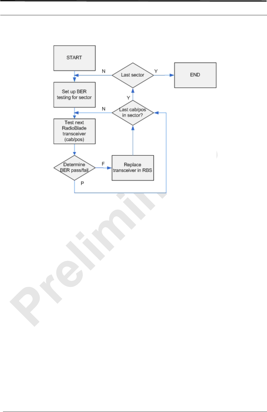
MC-Series ©2008 RadioFrame Networks, Inc. E-3
Proprietary and Confidential Information
MC-Series Standard Capacity system
998-1019-01 Rev X1
Figure E-1 BER Test Flow
E.5 Equipment Connection/Setup
Set up the equipment to measure Rx BER as follows:
1. Connect a laptop to port 8 of the ABIC CRIC using an Ethernet (CAT-5) cable.
2. Boot the laptop, start System Manager and log in.
3. Launch a browser session and then enter the MCSC system IP address (http://
192.168.200.5). Select the Performance Monitoring tab to display the login
window. Type the User Name, (Sysadmin, case sensitive), and Password
(Radioframe, case sensitive), and then select OK.
4. Connect Signal Generator to MCSC system
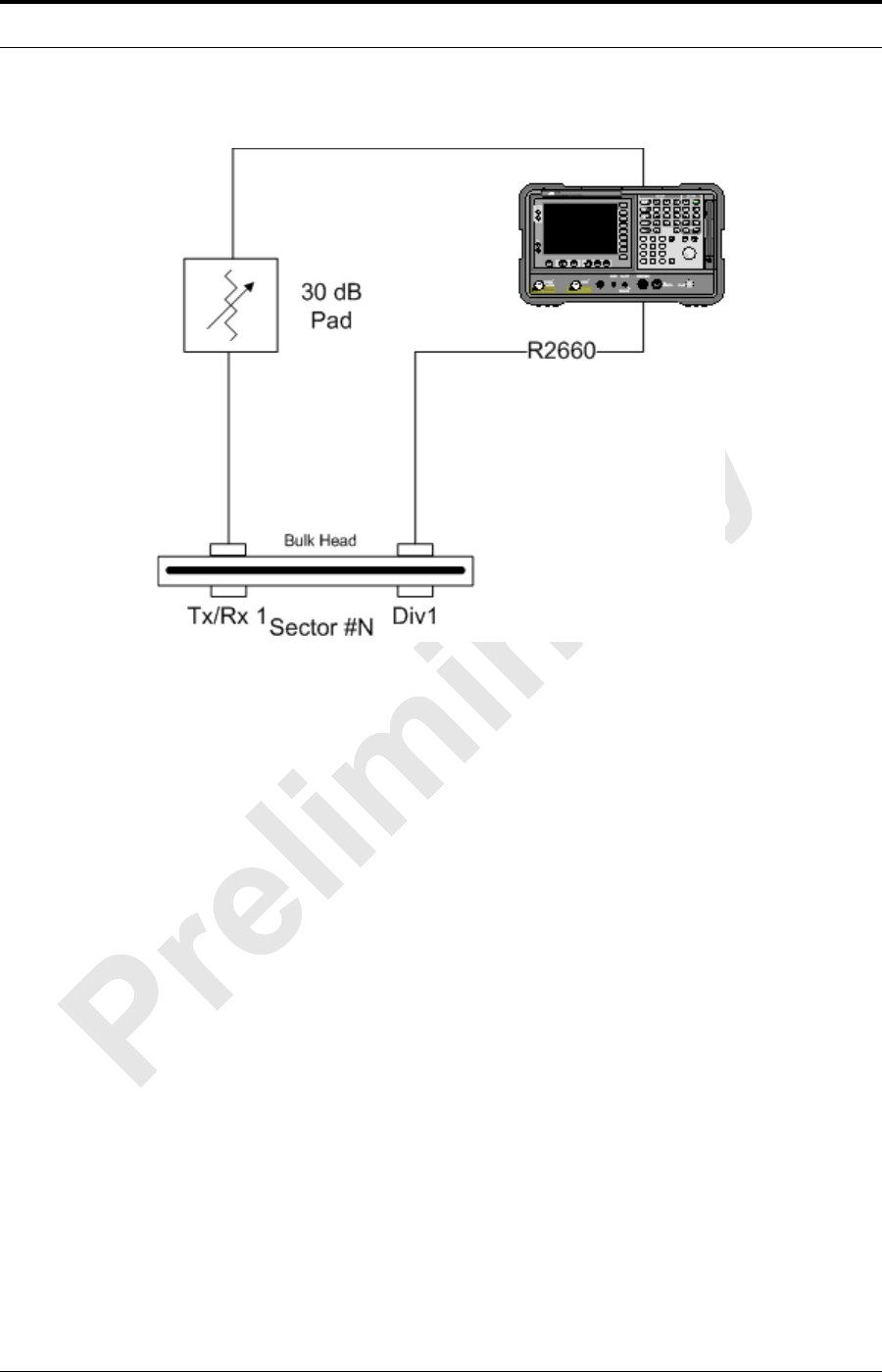
MC-Series Standard Capacity system 998-1019-01 Rev X1
E-4 ©2008 RadioFrame Networks, Inc. MC-Series
Proprietary and Confidential Information
Figure E-2 Test Equipment Connection
E.5.1 Motorola R2660
1. On the R2660, set the 10 MHz STD toggle switch to INT and power it up.
2. Connect the TOR Rx port that is being tested (e.g., 800 Rx1 to test 800 MHz)
to the RF IN/OUT or GEN OUT port on the R2660, depending on the desired
test signal level.
Note: Attenuate as required.
E.6 BER Test Procedure
Commonly, the BER test is performed during the process of commissioning an
MCSC system, and the system has not yet been brought online. If the test is to be
performed on a production system, the system must be taken out of service during a
maintenance window.
For your notes during the BER tests, there is a test notes master form, (Table E.1),
from which you can make copies. This form is useful both to organize your testing
strategy and preserve the record of test results.

MC-Series ©2008 RadioFrame Networks, Inc. E-5
Proprietary and Confidential Information
MC-Series Standard Capacity system
998-1019-01 Rev X1
E.7 RadioBlade Transceiver Pre-Test
This section covers preparation for testing: determining the status of the RadioBlade
transceivers in the system, taking the system out of service and preparing the
blades and Sig Gen to run the tests. These steps presume that you are logged in to
System Manager on the monitor laptop and that the Sig Gen is connected. Refer to
E.5 (Equipment Connection/Setup) .
1. Display the RadioBlade Control page ((Figure E-3)).
a. To navigate to this page from the System Manager home page.
b. Click the Performance Monitoring tab.
c. Click the RadioBlade Control link at the top of the iDEN Performance
Monitoring page.)
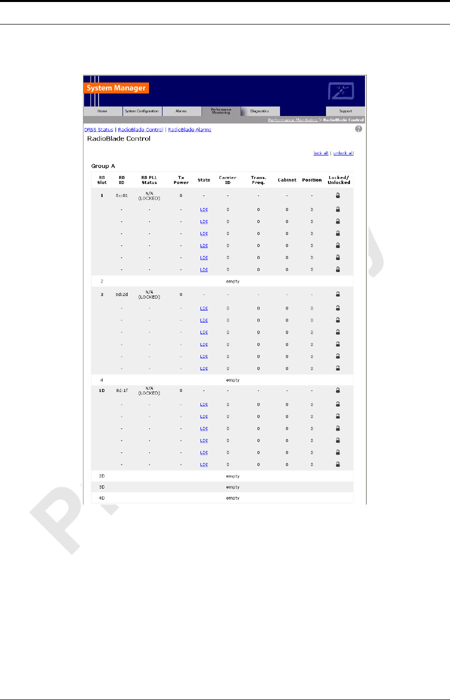
MC-Series Standard Capacity system 998-1019-01 Rev X1
E-6 ©2008 RadioFrame Networks, Inc. MC-Series
Proprietary and Confidential Information
Figure E-3 RadioBlade Control Page
RadioBlade transceivers are listed on the RadioBlade Control page by slot
number (1 through 24). If a RadioBlade transceiver is administratively
locked, the icon in the Locked/Unlocked column is closed. If the
RadioBlade transceiver is unlocked, the lock is open.
2. For reference in restoring the original system configuration, record in your
notes which RadioBlade transceivers are administratively locked.
3. Lock any unlocked RadioBlade transceivers so that none of them is
transmitting.

MC-Series ©2008 RadioFrame Networks, Inc. E-7
Proprietary and Confidential Information
MC-Series Standard Capacity system
998-1019-01 Rev X1
4. To lock a RadioBlade transceiver, select its open lock icon, and, when
prompted, select Accept. Or you can use the lock all hot link to
administratively lock all blades with one command.
E.7.1 RadioBlade Transceiver BER Test
This section covers the method to use to measure receiver BER and determine
whether each RadioBlade transceiver passes. Testing is organized by sector to
minimize the need to move the Sig Gen leads. Because you are testing an MCSC
system that is not in service, you can simply leave the leads connected to the
sector Rx port at TOR for the duration of the tests on that sector. The testing
method follows a nested loop (summarized in E.4 (Testing Strategy) ) until all
blades either pass or fail. Once testing on a given RadioBlade transceiver has
been completed (step 7 ) you repeat the test steps for the next transceiver. Once
a given sector is completely tested, you move the leads to the next sector input
port and repeat the test for each blade in the next sector.
1. Set the Motorola R2660 to generate an in-bound 1 x 6 test signal at the
desired frequency and signal level into the Rx port that corresponds to the
RadioBlade transceiver to be tested.
2. Determine the receive sensitivity threshold. Start at –120 dBm, and then
increase in 2 dB increments until the BER drops below 2%. The receive
sensitivity value should be less than –106 dBm at 2% BER.
3. Determine the max. level threshold. Start at –48 dBm and increase in 2 dB
increments until the BER goes above 2%. The maximum input power should
be greater than –40 dBm at 2% BER.
4. If either of the values called for in steps 2 and 3 is not attained, the
RadioBlade transceiver has failed specifications and should be replaced.
5. Display the RadioBlade Control page ((Figure E-3)), and make sure the
RadioBlade transceiver that is to be tested is not locked. If it is locked, unlock
it.
6. If you are unlocking the blade, refresh the page every 30 seconds until the
State of the RadioBlade transceiver has changed to ‘UEA’, approximately 3
minutes.
7. Select the Diagnostics tab ((Figure E-4)), and then select Bit Error Rate
Test.
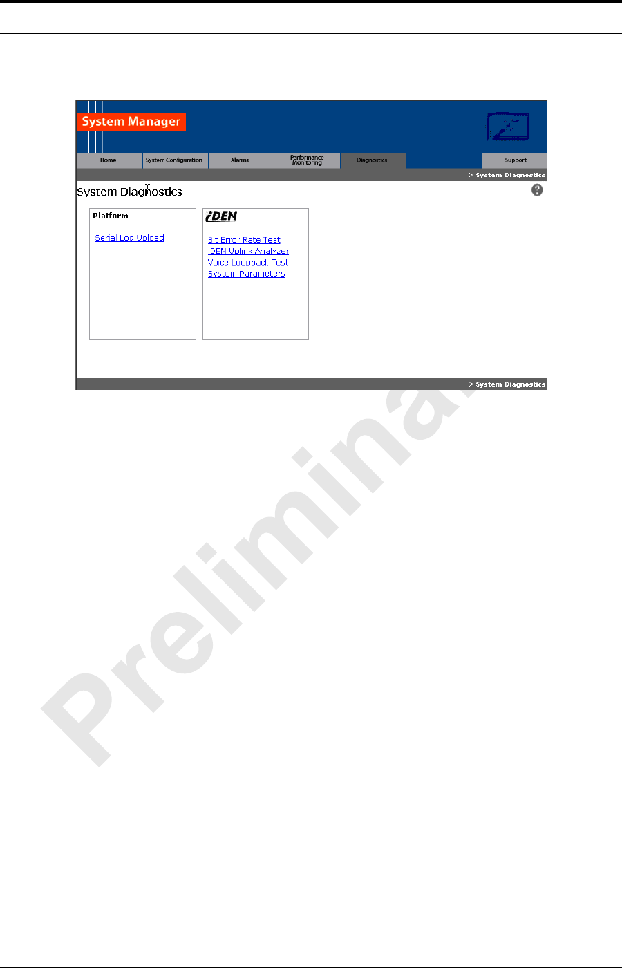
MC-Series Standard Capacity system 998-1019-01 Rev X1
E-8 ©2008 RadioFrame Networks, Inc. MC-Series
Proprietary and Confidential Information
Figure E-4 System Diagnostics Page
8. On the Bit Error Rate Test page ((Figure E-5)), select the RadioBlade
transceiver that is to be tested.
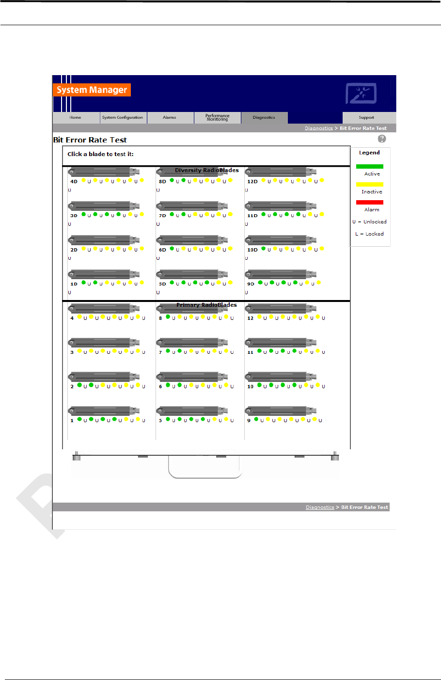
MC-Series ©2008 RadioFrame Networks, Inc. E-9
Proprietary and Confidential Information
MC-Series Standard Capacity system
998-1019-01 Rev X1
Figure E-5 Bit Error Rate Test Page
The Start Test page is formatted as shown in section F.3 explains the use
of the center carrier in BR testing with the MCRB.
9. Optionally, if the blade you are testing is an MCRB, you can enter a Center
Carrier (in decimal format); if no value is entered in this field, the band will be
centered on the specified carrier. Enter the Carrier ID (in decimal format) to
which the Sig Gen is set, and then select the Start Test button.
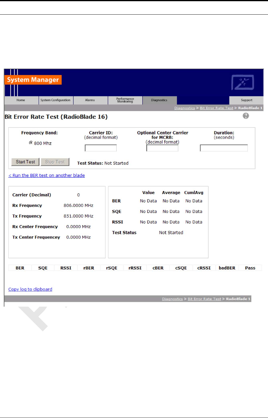
MC-Series Standard Capacity system 998-1019-01 Rev X1
E-10 ©2008 RadioFrame Networks, Inc. MC-Series
Proprietary and Confidential Information
“BER Test on an MCRB” in section E.4 (Testing Strategy) explains the use of
the center carrier in BR testing with the MCRB.
Figure E-6 Bit Error Rate Start Test Page
10. Verify that the displayed Rx Frequency matches the desired receive
frequency.
11. Approximately every second, the page reports the current BER
measurement (BER) and the running average of the ten latest BER
measurements (BER Avg). Record these results, and then select the Stop
Test button.

MC-Series ©2008 RadioFrame Networks, Inc. E-11
Proprietary and Confidential Information
MC-Series Standard Capacity system
998-1019-01 Rev X1
a. If the warning “Test Signal Timing Out of Lock” appears, cycle power to
the R2660 and set it up again to generate an in-bound 1x6 test signal at
the desired frequency and signal level into the Rx port. It may take a few
minutes for the R2660 test signal to stabilize.
b. If the only BER measurements reported are 50%, NO DATA, or both,
verify that all procedure steps have been completed. If no problems are
found, cycle power to the R2660 and set it up again to generate an in-
bound 1x6 test signal at the desired frequency and signal level into the
Rx port. It may take a few minutes for the R2660 test signal to stabilize.
If there's still no change after cycling power to the R2660, select the
Stop Test button.
12. When the BER test is complete, lock the RadioBlade transceiver that was
under test.
13. Display the RadioBlade Control page, and lock the RadioBlade transceiver
by selecting its lock icon so that it is closed (locked).
a. Refresh the page every 30 seconds until the State of the RadioBlade
transceiver has changed to ‘2’.
14. Repeat Steps 1 through 12 for each RadioBlade transceiver to be tested on
this Rx port.
15. Move the test leads to the next sector at TOR when all desired blades in the
current sector have been tested and repeat the procedure.
E.8 Equipment Disconnection
Note: Disconnect equipment after completing the BER
testing.
1. Disconnect the R2660 from the Rx port under test.
2. Display the DRBS Status page, and verify that all RadioBlade transceiver status
icons are green.
3. Disconnect the network cable from port 8 of the ABIC CRIC.
E.9 BER Test Notes Master
You can use this page to make copies of (Table E.1) for use as a handy organizer
and permanent record of the BER tests.

MC-Series Standard Capacity system 998-1019-01 Rev X1
E-12 ©2008 RadioFrame Networks, Inc. MC-Series
Proprietary and Confidential Information
Table E.1 BER Test Notes Master
Sector/
Test Seq. #
BR Freq./
Cent. Freq.
(MHz)
Sensitivity
Threshold
(dBm)
Max. Level
Threshold
(dBm)
Locked/
Unlocked
After Test? Pass/Fail
Cab. Pos.
MC-Series Standard Capacity system
998-1019-01 Rev X1
MC-Series ©2008 RadioFrame Networks, Inc. F-1
Proprietary and Confidential Information
Appendix F Dangerous RF Emissions Precautions
This equipment is designed to generate and radiate radio frequency (RF) energy by
means of an external antenna. When terminated into a non-radiating RF load, the
base station equipment is certified to comply with Federal Communications
Commission (FCC) regulations pertaining to human exposure to RF radiation in
accordance with the FCC Rules Part 1 section 1.1310 as published in title 47 code
of federal regulations and procedures established in TIA/EIA TSB92, Report on
EME Evaluation for RF cabinet Emissions Under FCC MPE Guidelines, Compliance
to FCC regulations of the final installation should be assessed and take into account
site specific characteristics such as type and location of antennas, as well as site
accessibility of occupational personnel (controlled environment) and the general
public (uncontrolled environment). This equipment should only be installed and
maintained by trained technicians. Licensees of the FCC using this equipment are
responsible for insuring that its installation and operation comply with FCC
regulations Part 1 section 1.1310 as published in title 47 code of federal regulations.
Whether a given installation meets FCC limits for human exposure to radio
frequency radiation may depend not only on this equipment but also on whether the
“environments” being assessed are being affected by radio frequency fields from
other equipment, the effects of which may add to the level of exposure.
Accordingly, the overall exposure may be affected by radio frequency generating
facilities that exist at the time the licensee’s equipment is being installed or even by
equipment installed later. Therefore, the effects of any such facilities must be
considered in site selection and in determining whether a particular installation
Warning!
The MCSC system has been approved for antennas up to +20 dBi. At energy
levels within the approved range, operation may present hazards to life and
health.
RF emission level is a function of the installation. Accordingly, it is the
responsibility of the equipment owner, and not RadioFrame Networks, Inc., to
apply signage to the site if it is required under 47 CFR 1.1310.
Please carefully read and observe the following warnings!
MC-Series Standard Capacity system 998-1019-01 Rev X1
F-2 ©2008 RadioFrame Networks, Inc. MC-Series
Proprietary and Confidential Information
meets the FCC requirements. FCC OET Bulletin 65 provides materials to assist in
making determinations if a given facility is compliant with the human exposure to RF
radiation limits. Determining the compliance of transmitter sites of various
complexities may be accomplished by means of computational methods. For more
complex sites direct measurement of power density may be more expedient.
Persons responsible for installation of this equipment are urged to consult the listed
reference material to assist in determining whether a given installation complies with
the applicable limits. In general the following guidelines should be observed when
working in or around radio transmitter sites:
Warning!
All personnel should have electromagnetic energy awareness training.
Warning!
All personnel entering the site must be authorized.
Warning!
Obey all posted signs.
Warning!
Assume all antennas are active.
MC-Series ©2008 RadioFrame Networks, Inc. F-3
Proprietary and Confidential Information
MC-Series Standard Capacity system
998-1019-01 Rev X1
Warning!
Before working on antennas, notify owners and disable appropriate transmitters.
Warning!
Maintain minimum 3 feet clearance from all antennas.
Warning!
Do not stop in front of antennas.
Warning!
Use personal RF monitors while working near antennas.
Warning!
Never operate transmitters without shields during normal operation.

MC-Series Standard Capacity system 998-1019-01 Rev X1
F-4 ©2008 RadioFrame Networks, Inc. MC-Series
Proprietary and Confidential Information
Warning!
Do not operate base station antennas in equipment rooms.

MC-Series Standard Capacity system
998-1019-01 Rev X1
MC-Series ©2008 RadioFrame Networks, Inc. G-1
Proprietary and Confidential Information
Appendix G Repair and Technical Support
G.1 RadioFrame Networks Support
RadioFrame Networks provides technical support services to for the installation,
operation and maintenance of RadioFrame Networks equipment. For iSCIII or T1/E1
related questions follow normal troubleshooting procedures.
Before calling...
Have the following information available prior to contacting RadioFrame Networks
Technical Assistance Center (TAC) to minimize downtime:
1. Location of the MCSC system.
2. MCSC system software version.
3. Symptoms of the problem.
4. If an alarm was generated, the alarm information from the Alarm Log in
System Manager.
5. Date the problem was first noticed.
6. If the problem can be reproduced.
7. What causes the problem to occur.
8. Any unusual circumstances contributing to the problem (i.e., loss of power).
G.1.1 Technical Support
For support of RadioFrame Networks equipment, contact the RadioFrame
Networks Technical Assistance Center (TAC) at:
(US) 1-800-328-0847
support@radioframenetworks.com

MC-Series Standard Capacity system 998-1019-01 Rev X1
G-2 ©2008 RadioFrame Networks, Inc. MC-Series
Proprietary and Confidential Information

MC-Series Standard Capacity system998-1019-01 Rev X1
MC-Series ©2008 RadioFrame Networks, Inc. GLS-1
Proprietary and Confidential Information
Term Definition
800E Extended 800 MHz Band (800S+800U)
8PSK 8 Phase Shift Keying. Phased Shift Keying is a form of phase modu-
lation using of a discrete number of states.
ARFCN Absolute radio frequency channel number
auto-baselining A CPE software download server (SWDLS) is used to upgrade a CPE
to the required AGW software version before it is allowed to connect
to its S-AGW.
Backhaul Using the back channel on a bi-directional communications line
BER Bit Error Rate
BNC Bayonet Neil-Concelman (BNC) coaxial connector
BR Base Radio
BTS Base Transceiver Station
BTUs British Thermal Units
CALEA Communications Assistance for Law Enforcement Act
CAT5 Category 5 (Cable)
CE Conformité Européenne
CLI Client editor
CPE Customer Premise Equipment
CRIC Combined RF Front-End Interface Card (cf. BLIC—CRIC refers to the
hardware implementation of the BTS LAN interface for the S-Series)
CSU Channel Service Unit
DACS Digital Access Carrier System
DAS Distributed Antenna System
DLC Digital Line Card
DSP Digital Signal Processor
EBRC Enhance Base Radio Controller
EFR Enhanced Full Rate
EML Element Management Layer
EMS Executive Management System
ERTM Ethernet Rear Transition Module. The ERTM provides Ethernet con-
nectivity between the BCU and S-AGW Linux server (QTA).
ESD Electro-static discharge
EVM Error Vector Magnitude. The difference between the received coordi-
nates (by phase and amplitude) and the intended position (e.g. the ac-
tual transmission).
FCC Federal Communication Commission
Glossary

MC-Series Standard Capacity system 998-1019-01 Rev X1
GLS-2 ©2008 RadioFrame Networks, Inc. MC-Series
Proprietary and Confidential Information
FPGA Field Programmable Gate Array
FNE Fixed Network Equipment
FOA First Office Application
FR Full Rate
FRU Field Replaceable Unit
GPL General Public License. Software license specifically developed to
maintain free access to a computer program even if changes or addi-
tions are made to the code.
GR General Release
GUI Graphical User Interface
HVAC heating, ventilating, and air conditioning
Hz Hertz
IEC International Electrotechnical Commission
IM Inter Modulation
INI Interference and Noise Indicator
IP Internet Protocol
ISP Internet Service Provider
ISTA International Safe Transit Association
LAN Local Area Network
LMT Local Management Terminal
MAC Medium Access Control
MCRB Multi-Channel RadioBlade
MDX Media Dependent Interface
MDIX Media Dependent Interface Crossover
MHz Megahertz
MOP Method of Procedure
MNO Mobile Network Operators
MS Mobile Station
MTBF Mean Time Between Failures
NEBS Network Equipment Building Systems
NSTA National Security Telecommunications Advisory
OLCC On Line Configuration Change
OMC Operations and Management Centre
OML Object Manipulation Language
OPM Outdoor Pole Mount
PCCH Primary Control Channel
PCM Pulse-Code Modulation
PCU Packet Control Unit
PDCH Packet Data Channel. A general term used in GPRS to represent a
GPRS control timeslot in place of conventional GSM circuit switching.
PDU Power Distribution Unit

MC-Series ©2008 RadioFrame Networks, Inc. GLS-3
Proprietary and Confidential Information
MC-Series Standard Capacity system998-1019-01 Rev X1
PLL Phase Locked Loop
Provisioning Term describing the providing of services to the user.
QoS Quality of Service
RAN Radio Access Network
RF Radio Frequency
ROM Read Only Memory
RMS Root Mean Square
RSL Request-and-Status Link
RSSI Received Signal Strength Indicator
Rx Receive
SCCH Secondary Control Channel
SMA Sub-miniature Version A
SNMP Simple Network Management Protocol
SQE Signal Quality Estimator
SR Software Release
SSH Secure Shell. Provides a secure channel between a local and a re-
mote computer.
SWDL Software Download
SWDLS Software Download Server
TBD To be determined
TCH Traffic Channel
TDM Time division multiplexing. Imbedding multiple data streams into a sig-
nal.
TEI Terminal Endpoint Identifier
TMN Telecommunications Management Network
TRD Technical Requirements Document
TRX Transceiver
Tx Transmit
UL Underwriters Laboratories
xDSL Generic term for the various types of DSL/
xU Standard unit of measure regarding the height of a computer or cabi-
net enclosure. For example 4U is an enclosure seven inches tall.

MC-Series Standard Capacity system 998-1019-01 Rev X1
GLS-4 ©2008 RadioFrame Networks, Inc. MC-Series
Proprietary and Confidential Information

MC-Series Standard Capacity system998-1019-01 Rev X1
MC-Series ©2008 RadioFrame Networks, Inc. Rev-1
Proprietary and Confidential Information
Feel free to use the Registration and Feedback format at the beginning of this document.
Submit comments and corrections to:
RadioFrame Networks, Inc.
Technical Information Department
9461 Willows Road NE, Suite 100
Redmond, WA 98052
Tel.: +1 425 278 2780 Fax: +1 425 278 2781
This document is also posted as a.pdf file on the RadioFrame Networks web site at:
http://www.radioframenetworks.com/partners
DATE REV DESCRIPTION
7/3/2007 X1 Preliminary port from Word into FrameMaker template
Revision History
MC-Series Standard Capacity system 998-1019-01 Rev X1
Rev-2 ©2008 RadioFrame Networks, Inc. MC-Series
Proprietary and Confidential Information
Acknowledgments
Related Documentation
Name Position
Document # Rev Document Title
998-4005-00 B MC Series Medium Power Implementation Guide
935-0003-00 A MC-Series Medium Power Feature Implementation Document (FID)
998-4012-03 A MC-Series High-Power Dual-Band System Implementation Guide
998-5000-01 A MC-Series Outdoor Pole Mount Implementation Guide for Guam Installation

Sign-off sheet
MC-Series ©2008 RadioFrame Networks, Inc.
Proprietary and Confidential Information
MC-Series Standard Capacity system998-1019-01 Rev X1
From: Technical Information
To: Reviewers
Re: MC-Series Standard Capacity system Implementation Guide
Date: February 13, 2008
Initials REVIEWER COMMENTS