RadioFrame Networks RFU7 iDEN RadioBlade User Manual iden spec sheet
RadioFrame Networks, Inc iDEN RadioBlade iden spec sheet
User Manual
EXHIBIT L – USER MANUAL
FCC ID# PURRFU7
981-0620-00 Rev A
RadioFrame Networks™, Inc.; 18211 NE 68th St. Suite E-120 Redmond, WA 98052
sales: info@radioframenetworks.com or 425.883.2088
iDEN RadioBlade
FCC Compliance
This device complies with part 15 of the FCC Rules. Operation is subject to the following two conditions:
1) This device may not cause harmful interference, and
2) this device must accept any interference received, including interference that may cause undesired operation.
This equipment has been tested and found to comply with the limits for a Class A digital device, pursuant to part 15 of the FCC
Rules. These limits are designed to provide reasonable protection against harmful interference when the equipment is
operated in a commercial environment. This equipment generates, uses, and can radiate radio frequency energy and, if not
installed and used in accordance with the instruction manual, may cause harmful interference to radio communications.
Operation of this equipment in a residential area is likely to cause harmful interference, in which case the user will be required
to correct the interference at his own expense.
Caution
Changes or modifications not expressly approved by the party responsible for compliance could void the user's authority to
operate the equipment.
Specifications
Agency Compliance
FCC Class A CSA 22.2 No. 60950
ISTA 2A transit
Operating Environment
• Operating Ambient Temperature: +0oC to
+55oC (+32oF to +131oF)
• Storage Temperature: -40oC to +70oC (-40oF
to +158oF)
• Relative Humidity: 10-90% non condensing
• Altitude: -200 to +8000 feet above mean sea
level; above 8000', reduce maximum
operating ambient temperature by 2oC per
1000' to a maximum of 13000'
• Shock: 40 g’s
• Vibration: Level 3 earthquake
• Keep product free from dust, wind, salt, liquids
Physical Specifications
• Dimensions: 3" wide x 4" high (plus antenna) x 0.5" thick
(approx.)
• Weight: 1 lb (approx.)
Input Power
• 3.3 VDC, 720mA max
• 2.5 VDC, 50mA max
Tx and Rx Power and Center Frequency Ranges
• Tx center frequency range: 851.0125 to 869.9875MHz
Tx power range: -20 to +8dBm +/-3dB
• Rx center frequency range: 806.0125 to 824.9875MHz
981-0620-00 Rev A
Installation Instructions and Guidelines
1. Find these items in the shipping box: up to four (4) iDEN RadioBlades in individually wrapped anti-static bags.
2. Insert one iDEN RadioBlade into the specified slot in the RadioFrame Unit (RFU) as shown in the diagram above. For
safe operation, follow these guidelines:
• Do not mount the unit in any orientation other than that specified in the diagram.
• Do not force the RadioBlade, or damage to equipment can occur.
• Slide the top of the RadioBlade into the metal slot on top of the RFU until the RadioBlade connector seats firmly into
the backplane.
Copyrights/Trademarks/Warranty
RadioFrame Networks, RadioBlades, and the RadioFrame Networks logo are trademarks or service marks of RadioFrame Networks™, Inc.
You may not use these or any other RadioFrame Networks trademarks or service marks without the written permission of RadioFrame
Networks™, Inc. All other trademarks and trade names are the property of their respective owners.
RadioFrame Networks warrants that this product is new and free from defects in materials, workmanship, and design. This warranty will
continue for one (1) year following installation of the product at a customer site.

RadioFrame System
Installation Guide
Version 1.0
http://www.radioframenetworks.com
September 2001
981-6200-00 Rev A

ii
The specifications and information regarding the products in this manual are subject to change without notice. All
statements, information, and recommendations in this manual are believed to be accurate but are presented without
warranty of any kind, express or implied. Users must take full responsibility for their application of any products.
United States Federal Communications Commission Notice
The following information is for FCC compliance of Class A devices: This equipment has been tested and found to comply
with the limits for a Class A digital device, pursuant to part 15 of the FCC rules. These limits are designed to provide
reasonable protection against harmful interference when the equipment is operated in a commercial environment. This
equipment generates, uses, and can radiate radio-frequency energy and, if not installed and used in accordance with the
instruction manual, may cause harmful interference to radio communications. Operation of this equipment in a residential
area is likely to cause harmful interference, in which case users will be required to correct the interference at their own
expense. Changes or modifications not expressly approved by the party responsible for compliance could void the user’s
authority to operate the equipment.
Limited Warranty
Hardware. RadioFrame Networks warrants that this product is new and free from defects in materials, workmanship, and
design. This warranty will continue for one (1) year following installation of the product at a customer site. In no event shall
RadioFrame Networks or its suppliers be liable for any indirect, special, consequential, or incidental damages, including,
without limitation, lost profits or loss or damage to data arising out of the use or inability to use this manual, even if
RadioFrame Networks or its suppliers have been advised of the possibility of such damages.
Software. RadioFrame Networks warrants that commencing from the date of delivery to customer and continuing for a
period of one (1) year, the Software substantially conforms to its published specifications. Except for the foregoing, the
Software is provided AS IS. This limited warranty extends only to the customer who is the original licensee. Customer’s
sole and exclusive remedy and the entire liability of RadioFrame Networks and its suppliers under this limited warranty will
be, at RadioFrame Networks’ option, repair or replacement of the Software if reported to RadioFrame Networks. In no
event does RadioFrame Networks warrant that the Software is error free or that customer will be able to operate the
Software without problems or interruptions. In addition, due to the continual development of new techniques for intruding
upon and attacking networks, RadioFrame Networks does not warrant that the Software or any equipment, system or
network on which the Software is used will be free of vulnerability to intrusion or attack.
Restrictions
This warranty does not apply if the Product (a) has been altered, except by RadioFrame Networks, (b) has not been
installed, operated, repaired, or maintained in accordance with the instructions supplied by RadioFrame Networks, (c) has
been subjected to abnormal physical or electrical stress, misuse, negligence, or accident; or (d) is sold or, in the case of
Software, licensed, for beta, evaluation, testing, or demonstration purposes for which RadioFrame Networks does not
receive a payment of purchase or license fee.
Trademark Notice
RadioFrame Networks, RadioBlades, Network Chassis Unit, Airlink Chassis Unit, and the RadioFrame Networks logo are
trademarks or service marks of RadioFrame Networks™, Inc. You may not use these or any other RadioFrame Networks
trademarks or service marks without the written permission of RadioFrame Networks™, Inc. All other trademarks and
trade names are the property of their respective owners.
RadioFrame System Installation Guide
Copyright © 2001, RadioFrame Networks, Inc.
All rights reserved.

iii
Contents
ABOUT THIS GUIDE IV
Audience ................................................................................................................ v
Conventions ........................................................................................................... v
Obtaining Service and Support ............................................................................. vi
1 PREPARING FOR THE INSTALLATION 1
The RadioFrame System ....................................................................................... 1
Tools and Parts Required ...................................................................................... 5
Safety Precautions ................................................................................................. 5
2 INSTALLING THE RFS 11
Identify the RFS Installation Locations................................................................. 11
Wire the RFS........................................................................................................ 12
Unpacking the RFS .............................................................................................. 12
Install the NCU ..................................................................................................... 13
Install the ACUs ...................................................................................................15
Install the RFUs.................................................................................................... 18
Verify the System ................................................................................................. 22
Connect the RFS to the iSC................................................................................. 23
Connect the NCU to the iSC.......................................................................... 23
Connect the NCU to the Timing Source ........................................................ 24
3 TROUBLESHOOTING 27
Network Chassis Unit........................................................................................... 28
Airlink Chassis Unit .............................................................................................. 30
RadioFrame Unit .................................................................................................. 32
GLOSSARY .................................................................................. 34
HARDWARE SPECIFICATIONS.................................................. 36
INDEX ........................................................................................... 38

iv
About This Guide
This guide provides hardware installation procedures and information for the
RadioFrame System (RFS). The guide is organized as follows:
Chapter Title Description
1 Preparing for the Installation Describes the RadioFrame System, its
components and features, tools and parts
required for the installation, as well as safety
recommendations, warnings, and guidelines.
NOTE: Read all safety precautions before
attempting to install the RFS or any of its
components.
2 Installing the RadioFrame
System
Includes step-by-step instructions for
unpacking, mounting, wiring, connecting, and
verifying all RFS components.
3 Troubleshooting Includes instructions for resolving problems
encountered during the installation.
Glossary Describes terms used in this guide.
Hardware Specifications For each RFS component.
About This Guide
v
Audience
This guide is intended for Field Service Technicians who will be installing the
RadioFrame System. Such individuals must be familiar with electronic circuitry
and wiring practices and have experience as an electronic or electromechanical
technician. Installers shall have the following knowledge, training, and
capabilities:
• RadioFrame System Certification
• CAT 5 and coaxial cabling installation
• General building practices, for example mounting in drywall and concrete
drilling
Conventions
Convention Description
Note
Notes describe operational or informational hints or tips.
Caution
Cautions describe situations where damage can occur to
equipment if directions are not properly followed.
Warning!
Warnings describe situations where bodily harm can occur if
directions are not properly followed.

About This Guide
vi
Obtaining Service and Support
For questions pertaining to system and product functions, features,
specifications, and requirements during installation, contact RadioFrame
Networks customer support.
Telephone (425) 883-2088
Website www.radioframenetworks.com
E-mail customersupport@radioframenetworks.com
Postal mail RadioFrame Networks, Inc.
18211 NE 68th St., Suite E-120
Redmond, WA 98052
For service and support of a RadioFrame System purchased from a reseller,
contact the reseller.

1
1
Preparing for the Installation
This section describes the RadioFrame System, its components, features and
functions, tools required for the installation, and safety precautions.
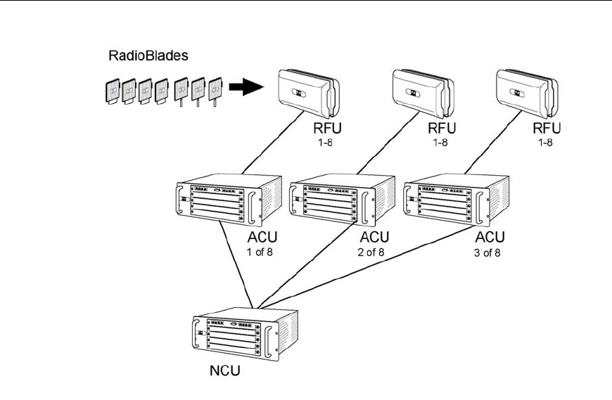
The RadioFrame System
The RadioFrame System (RFS) is a configurable indoor wireless system capable
of supporting multiple air interfaces simultaneously. The system is scaleable for
various applications and offers highly automated features.
Each RFS consists of at least one Network Chassis Unit™ (NCU) connected to as
many as 8 Airlink Chassis Units™ (ACUs). Each ACU connects up to 8
RadioFrame Units (RFUs), and each RFU contains up to 7 RadioBlades™. Each
RadioBlade supports one of several voice and wireless data standards, including
GSM, CDMA, iDEN, and 802.11b (WLAN).
The RadioFrame System:
• Supports multiple standards, including GSM, CDMA, iDEN, 802.11b
(WLAN), and many others.
Preparing for the Installation
2
Figure 1 The RadioFrame System consists of one NCU, up to 8 ACUs, and
up to 8 RFUs per ACU. Each RFU can hold up to 7 RadioBlades.
• Is modular and scaleable to increase operator flexibility.
• Is designed for easy installation with CAT 5 wiring and remote power for
antenna units.
• Is easy to deploy and manage with web browser and SNMP management
interfaces.
• Increases operator efficiency through plug-and-play features.
• Provides a simulcasting option for increased coverage and capacity usage.
• Provides SS7 for mobility.
• Provides PBX Interworking for enterprise features and reduced costs.
Preparing for the Installation
3
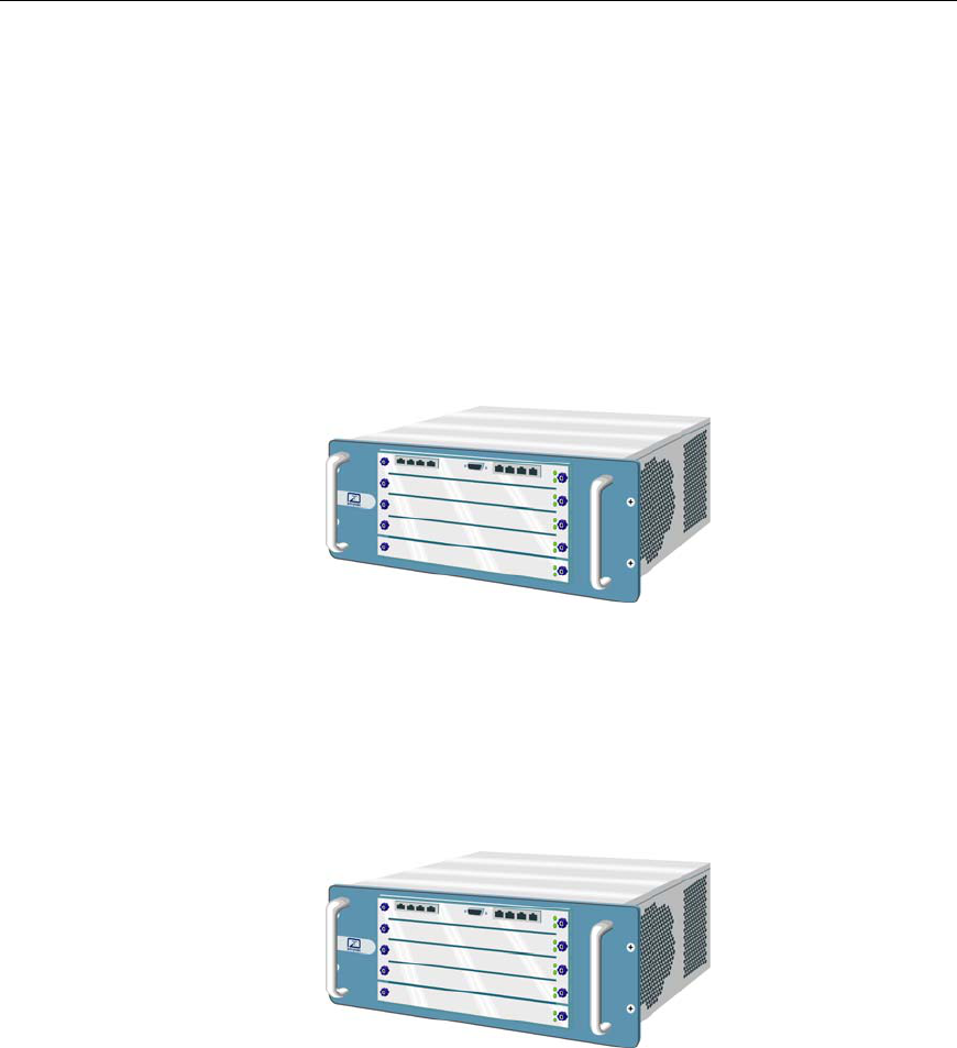
Network Chassis Unit or NCU
The Network Chassis Unit is the main controller of the RFS, providing external
network interfaces and the baseband network processing for the ACUs and
RFUs. The NCU also is the interface between the RFS and the
telecommunications switching entities. The NCU is 7” high x 19” wide x 13”
deep, powered by 120VAC, and rack mounted. Connections are CAT 5 (RJ45)
except power, an EIA-232 interface, two BNC ports, and an SMB port for GPS
antenna connection. The NCU connects up to 8 ACUs, a WLAN, and in iDEN
installations, an iSC (integrated Site Controller). An RFS with a single NCU
provides a coverage area of up to 2 million square feet.
Figure 2 The NCU is the main controller of the RFS.
Airlink Chassis Unit or ACU
The Airlink Chassis Unit provides the baseband airlink processing for up to 8
RadioFrame Units, providing a coverage area up to 250,000 square feet. The
Figure 3 The ACU provides the airlink processing functions for the system.
Preparing for the Installation
4
ACU is the interface between the RFUs and the Network Chassis Unit, and
provides power, signals, and timing to the RFUs. The ACU is 7” high x 19” wide
x 13” deep, powered by 120VAC, and rack mounted. All connections are CAT 5
(RJ45) except for power.
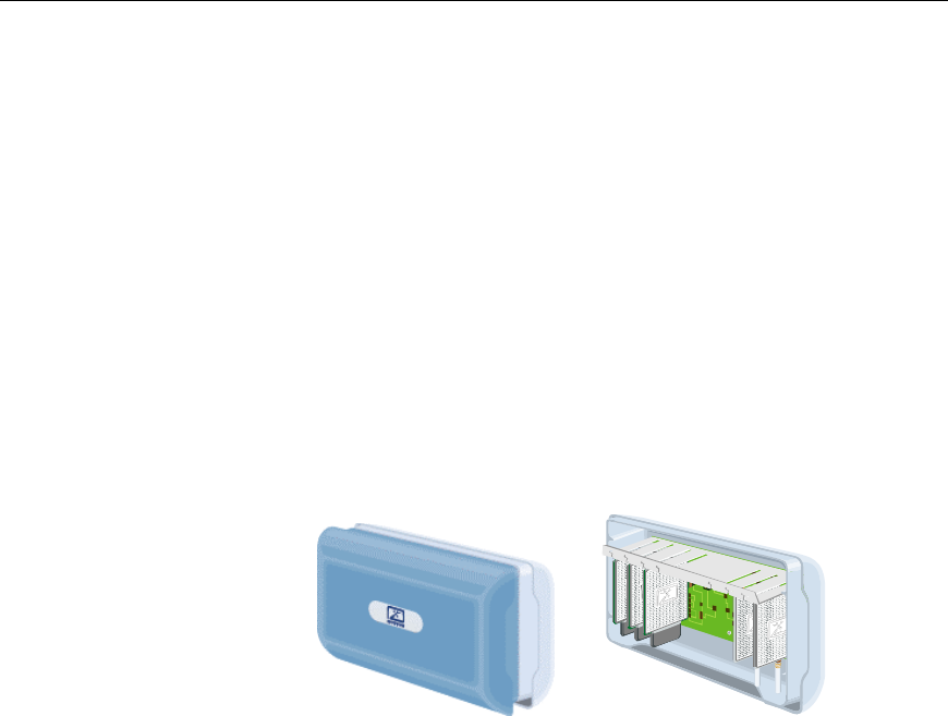
RadioFrame Unit or RFU
The RadioFrame Unit serves as the access interface between signals received
from mobile terminals, via a standard air interface, and the airlink processing
performed in the ACU. The RFU is approximately 8” high x 13.5” wide x 5” deep
and mounts conveniently on a wall, or on or above the ceiling to serve a coverage
area up to 32,000 square feet (100’ cell radius). The RFU connects to the ACU via
a single CAT 5 connection, receiving its power, signals, and timing from the
ACU. Each RFU holds up to 7 RadioBlades.
Figure 4 Each RFU holds up to 7 RadioBlades.
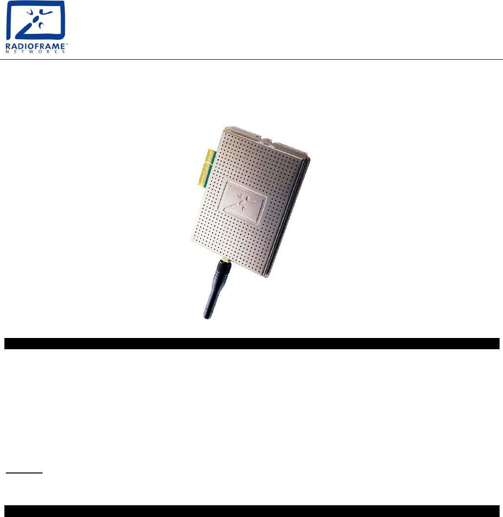
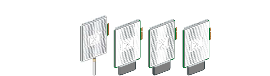
RadioBlades
Each RadioBlade provides a single RF channel transceiver supporting one of
several voice and wireless data standards, including GSM, CDMA, iDEN,
802.11b (WLAN), and many others. Each RadioBlade is approximately
4” high x 1/2” wide x 3” deep and inserts into a slot in the RFU. Each RadioBlade
contains an onboard omni antenna and provides a coverage area of
approximately 32,000 square feet (nominal 100’ radius cell).
Preparing for the Installation
5
Figure 5 Each RadioBlade supports one standard platform including GSM,
CDMA, iDEN, 802.11b (WLAN), and many others.
Tools and Parts Required
The RadioFrame System comes with all the parts necessary to mount each
component of the system. Tools required to mount the system components are as
follows:
• #2 Phillips screw driver
• For RFU ceiling mounts, drill with 3/16” bit for use with provided wood
screws, or a 9/32” bit and four ¼” bolts (not provided)
Safety Precautions
Read all the notices in this section prior to installing or using the RadioFrame
System or any of its components, including the Network Chassis Unit (NCU),
Airlink Chassis Unit (ACU), RadioFrame Unit (RFU), or RadioBlade.
Safety Recommendations
• Keep tools away from walk areas where you and others could fall over them.
• Wear safety glasses if you are working under any conditions that might be
hazardous to your eyes.
Preparing for the Installation
6
• Do not perform any action that creates a potential hazard to people or makes
the equipment unsafe.
Safety Warnings
Warning!
Only trained and qualified personnel should be allowed to install,
replace, or service this equipment.
Warning!
This product relies on the building’s installation for short-circuit (over
current) protection. Ensure that a fuse or circuit breaker no larger than
120 VAC, 15A U.S. (240 VAC, 10A international) is used on the phase
conductors (all current-carrying conductors).
Warning!
To comply with FCC RF exposure requirements, iDEN antennas must be
installed to provide at least 20cm separation from all persons, with
antenna gain not exceeding 0 dBi.
Warning!
Never defeat the ground conductor or operate the equipment in the
absence of a suitably installed ground conductor. Contact the appropriate
electrical inspection authority or an electrician if you are uncertain that
suitable grounding is available.
Warning!
The plug-socket combination must be accessible at all times because it
serves as the main disconnecting device.

Preparing for the Installation
7
Warning!
The RadioFrame Unit (RFU) is intended to be mounted on a wall. The
RFU can also be installed on or above a ceiling. Please read the RFU
mounting instructions carefully before beginning installation. Failure to
use the correct hardware or to follow the correct procedures could result
in a hazardous situation to people and damage to the system.
Warning!
Ultimate disposal of this product should be handled according to all
national laws and regulations.

Preparing for the Installation
8
Safety with Electricity
Warning!
To avoid electric shock, do not connect safety extra-low voltage (SELV)
circuits to telephone-network voltage (TNV) circuits. LAN ports contain
SELV circuits, and WAN ports contain TNV circuits. Some LAN and
WAN ports both use RJ45 connectors; incorrect interconnection can cause
equipment damage. Use caution when connecting cables.
Warning!
Before working on equipment that is connected to power lines, remove
jewelry (including rings, necklaces, and watches). Metal objects will heat
up when connected to power and ground and can cause serious burns or
weld the metal object to the terminals.
Warning!
Hazardous network voltages are present in WAN ports regardless of
whether power to the attached equipment is OFF or ON. To avoid electric
shock, use caution when working near WAN ports. When detaching
cables, detach the end away from the router first.
Warning!
Before opening the NCU or ACU, disconnect the telephone-network
cables to avoid contact with telephone-network voltages.
Warning!
Do not touch the power supply when the power cord is connected. For
systems with a power switch, line voltages are present within the power
supply even when the power switch is off and the power cord is
connected. For systems without a power switch, line voltages are present
within the power supply when the power cord is connected.

Preparing for the Installation
9
Guidelines for Working on Equipment Powered by Electricity
• Locate the emergency power off switch for the room in which you are
working. Then, if an electrical accident occurs, you can act quickly to turn off
the power.
• Before installing, removing, or repairing an NCU or ACU, unplug the power
cord.
• Disconnect all power before working near power supplies.
• Do not work alone if potentially hazardous conditions exist.
• Never assume that power is disconnected from a circuit. Always check.
• Look carefully for possible hazards in your work area, such as moist floors,
ungrounded extension cables, frayed power cords, and missing safety
grounds.
In the Event of an Electrical Accident
• Use caution; do not become a victim yourself.
• Turn off power to the system.
• If possible, send another person to get medical aid. Otherwise, assess the
condition of the victim and then call for help.
• Determine if the victim needs rescue breathing or external cardiac
compressions, then take appropriate action.
Preventing Electrostatic Discharge Damage
Electrostatic discharge (ESD) can damage equipment and impair electrical
circuitry. It occurs when electronic printed circuit cards are improperly handled
and can result in complete or intermittent failures. Always follow ESD
prevention procedures when removing and replacing cards.

Preparing for the Installation
10
Ensure that the NCU or ACU is electrically connected to earth ground. Wear an
ESD-preventive wrist strap, ensuring that it makes a good skin contact. Connect
the clip to an unpainted surface of the chassis frame to safely channel unwanted
ESD voltages to ground. To properly guard against ESD damage and shocks, the
wrist strap and cord must operate effectively. If no wrist strap is available,
ground yourself by touching the metal part of the chassis.
Caution
For safety, periodically check the resistance value of the antistatic strap,
which should be between 1 and 10 megohm (Mohm).

11
2
Installing the RFS
The RadioFrame System is modular and simple to install using the Site Design
Specification (SDS). The SDS specifies the following:
• Location of each system component: NCU, ACUs, RFUs, and RadioBlades.
• Mounting type for each component: rack, wall, or ceiling.
• Cabling requirements, including maximum cabling lengths, existing
wiring/raceways that can be used, and terminations and connections
required.
• Locations of approved power sources for each NCU and ACU.
Identify the RFS Installation Locations
Refer to the Site Design Specification (SDS) to determine the installation location
of each component of the RFS. The NCU is typically installed in a
telecommunications room or other closet, ACUs are installed in a similar location
depending on the system layout, and each RFU is installed on a wall or on or
above a ceiling in open areas of the building. RadioBlades are inserted into each
RFU.

Installing the RadioFrame System
12
Wire the RFS
All components of the RFS are connected using standard CAT 5 cabling installed
in existing raceways or conduits when available. Use only RJ45 connectors for
system components. The NCU may also be connected to a wireless LAN
(WLAN), and in iDEN installations, the NCU must be connected to the iSC
(integrated Site Controller). All wiring specifications, including acceptable run
lengths and termination points, are listed in the Site Design Specification (SDS).
Wire the RFS according to the Site Design Specification
1 Run CAT 5 cabling between RFS components, and terminate the cabling
according to the SDS.
2 Label all termination points according to the SDS.
3 Test the cabling as specified by the SDS.
Unpacking the RFS
Each NCU, ACU, and RFU is shipped in its own box, and RadioBlades are
shipped several to a box in individually wrapped anti-static packaging. In iDEN
installations, an Ethernet Media Converter may also be provided in its own
container with the cables necessary to install it.
Unpack each unit only at the time of installation—leave items in their shipping
containers until ready for use. Unpacking instructions are contained inside each
shipping container.

Installing the RadioFrame System
13
Install the NCU
The NCU is the main controller of the RadioFrame System. Typically, the NCU is
mounted in a rack in a telecommunications room or other closet supplied with
120VAC.
Unpack and mount the Network Chassis Unit (NCU)
1 Find these items in the NCU shipping container: one NCU, four mounting
screws, one 120VAC power cord, one coaxial cable with two male BNC
connectors, and one set of product documentation.
2 Mount the NCU only in an EIA-standard compliant (19”) rack using all 4 screws
provided. Refer to the SDS for the exact location of the NCU. For safe operation,
follow these guidelines:
• Do not mount the NCU in any orientation other than that specified in the
following illustration.
• Mount the NCU so that both the front and the back are accessible.
• If the mounting holes do not line up, adjust the NCU up or down until the
mounting holes line up.
Caution
Do not block the air vents on the sides or rear of the NCU.
3 Plug the NCU into an approved power source (for more information, refer to
“Hardware Specifications”).
4 Verify that the NCU is receiving power and that each NCU card is operational.
Each card installed in the front and back of the NCU has two LEDs: Power and
Status. All LEDs should light green. If any LEDs do not light or are red, refer to
“Troubleshooting.”
Note!
The Status li
g
ht on the top card in the front of the NCU will remain red
until the NCU is connected to a timing source.
Installing the RadioFrame System
14
Figure 6 Mount the NCU only in an EIA-standard compliant 19” rack.
Connect the ACU patch cables to the NCU
1 Connect each ACU RJ45-to-RJ45 CAT 5 patch cable to the specified RJ45 port
(1-8) on the back of the NCU (see Figure 10).
Refer to the Site Design Specification to determine which ACU connects to each
port on the NCU. The Activity and Link LEDs above each NCU port will remain
unlit until each ACU has been installed and plugged in.
Installing the RadioFrame System
15
Figure 7 Connect each RJ45 port on the back of the NCU to the associated
ACU.
Install the ACUs
The method used to mount an Airlink Chassis Unit (ACU) is the same as for an
NCU. Typically, mount an ACU, then install all the RFUs associated with that
ACU by completing the procedure “Install the RFUs” next in this guide. Repeat
the procedures “Install the ACU” and “Install the RFUs” for each ACU
installation.
Unpack and mount the Airlink Chassis Unit (ACU)
1 Find these items in the ACU shipping container: one ACU, four mounting
screws, and one 120VAC power cord.
2 Mount the ACU only in an EIA-standard compliant (19”) rack using all 4 screws
provided. Refer to the SDS for the exact location of the ACU. For safe operation,
follow these guidelines:
• Do not mount the ACU in any orientation other than that specified in the
following illustration.
• Mount the ACU so that both the front and the back are accessible.
Installing the RadioFrame System
16
• If the mounting holes do not line up, adjust the ACU up or down until the
mounting holes line up.
Caution
Do not block the air vents on the sides or rear of the ACU.
3 Plug the ACU into an approved power source (for more information refer to
“Hardware Specifications”).
4 Verify that the ACU is receiving power and that each ACU card is operational.
Each card installed in the front and back of the ACU has two LEDs: Power and
Status. All LEDs should light green. If any LEDs do not light or are red, refer to
“Troubleshooting.”
Figure 8 Mount the ACU only in an EIA-standard compliant 19” rack.
Installing the RadioFrame System
17
Connect the ACU to the NCU and the ACU to the RFUs
1 Connect Port 1 on the front of the ACU to the specified port on the back of the
NCU using an RJ45-to-RJ45 CAT 5 cable.
2 Verify that the ACU is connected to the NCU.
The Link and Activity LEDs above Port 1 should both light green, and the
Activity LED should blink rapidly indicating that the connection to the NCU is
operating. If the LEDs do not come on, refer to “Troubleshooting.”
3 Connect each RFU to the specified port (1-8) on the back of the ACU using RJ45-
to-RJ45 CAT 5 patch cables.
The Link and Activity LEDs above each RFU port will remain unlit until each
RFU has been installed.
Figure 9 Connect Port 1 on the front of the ACU to the specified port on the
back of the NCU, and Ports 1 through 8 on the back of the ACU to
each RFU.

Installing the RadioFrame System
18
Install the RFUs
RadioFrame Units are all installed on a wall or on or above the ceiling. First,
mount an RFU, then connect it to the ACU and verify that the RFU is receiving
power from the ACU. Then, insert the RadioBlades into the RFU in the
configuration specified in the Site Design Specification (SDS).
Warning!
The RadioFrame Unit (RFU) is to be fix-mounted on indoor permanent
structures providing a separation distance of at least 20 cm from all persons
during normal operation and 10 feet from other RFU mounted assemblies.
Mount the RadioFrame Units (RFUs)
1 Find these items in the RFU shipping container: one RFU, mounting screws and
anchors, two mounting templates (wall and ceiling), and one ceiling bracket.
2 Complete one of the following procedures, “Wall Mount” or “Ceiling Mount” for
the specified location of the RFU.
Warning!
Do not touch the backplane (board) inside the RFU. A shock may
result.
Wall Mount
1 Place the 11” x 17” drawing template (P/N 981-1020-00) on the wall where the
RadioFrame Unit is to be mounted.
2 Mark the two locations indicated on the template.
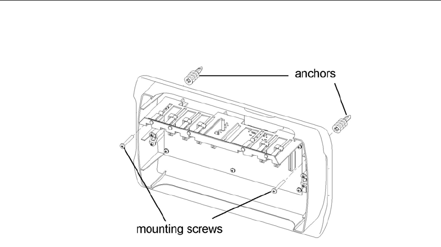
3 Screw the two supplied anchors into the locations as shown.
4 Screw the two supplied screws into the anchors, leaving approximately 1/4” of
each screw exposed.
5 Hang the RFU on the anchors and fully tighten both screws.
Installing the RadioFrame System
19
Figure 10 A wall mount requires two screws to anchor the RFU.
Ceiling Mount
1 Place the 8.5” x 11” drawing template (P/N 981-1010-00) on the ceiling where the
RFU is to be mounted.
2 Mark the four locations indicated on the template.
3 Drill four holes with the appropriately sized bit: 3/16” for the provided wood
screws, or 9/32” for 1/4” bolts (bolts not provided).
If using the provided wood screws, ensure that all four screws penetrate wood.
Otherwise, use alternative mounting screws or bolts to secure the ceiling bracket.
4 Using four screws or bolts, attach the ceiling bracket to the ceiling as shown.
5 Attach the RFU to the ceiling mount bracket and fully tighten the thumbscrew.
Installing the RadioFrame System
20
Figure 11 Use the provided bracket when mounting an RFU on the ceiling,
ensuring that all bolts or screws penetrate wood.
Connect the RFU to the ACU
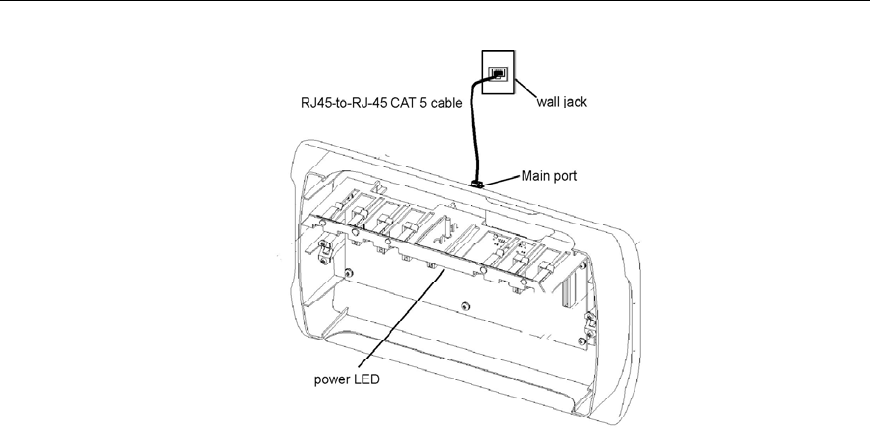
1 Connect the RJ45 port labeled MAIN on the top of the RFU to the wall jack using
an RJ45-to-RJ45 CAT 5 cable (see the following illustration).
Caution
Do not remove the protective cover from or use the RFU port labeled
AUX. Damage may occur to the RFU, ACU, or both.
2 Verify that the RFU is receiving power and connectivity from the ACU.
The Link and Activity LEDs on the MAIN port should light as green, and the
Activity LED should blink rapidly indicating connectivity. The LED on the
backplane should also light as green. If any LEDs do not light, refer to
“Troubleshooting.”
3 Complete the next procedure “Insert the RadioBlades” before placing the front
cover on the RFU.
Installing the RadioFrame System
21
Figure 12 Connect the RFU to the ACU and ensure that the RFU is receiving
power and connectivity from the ACU.
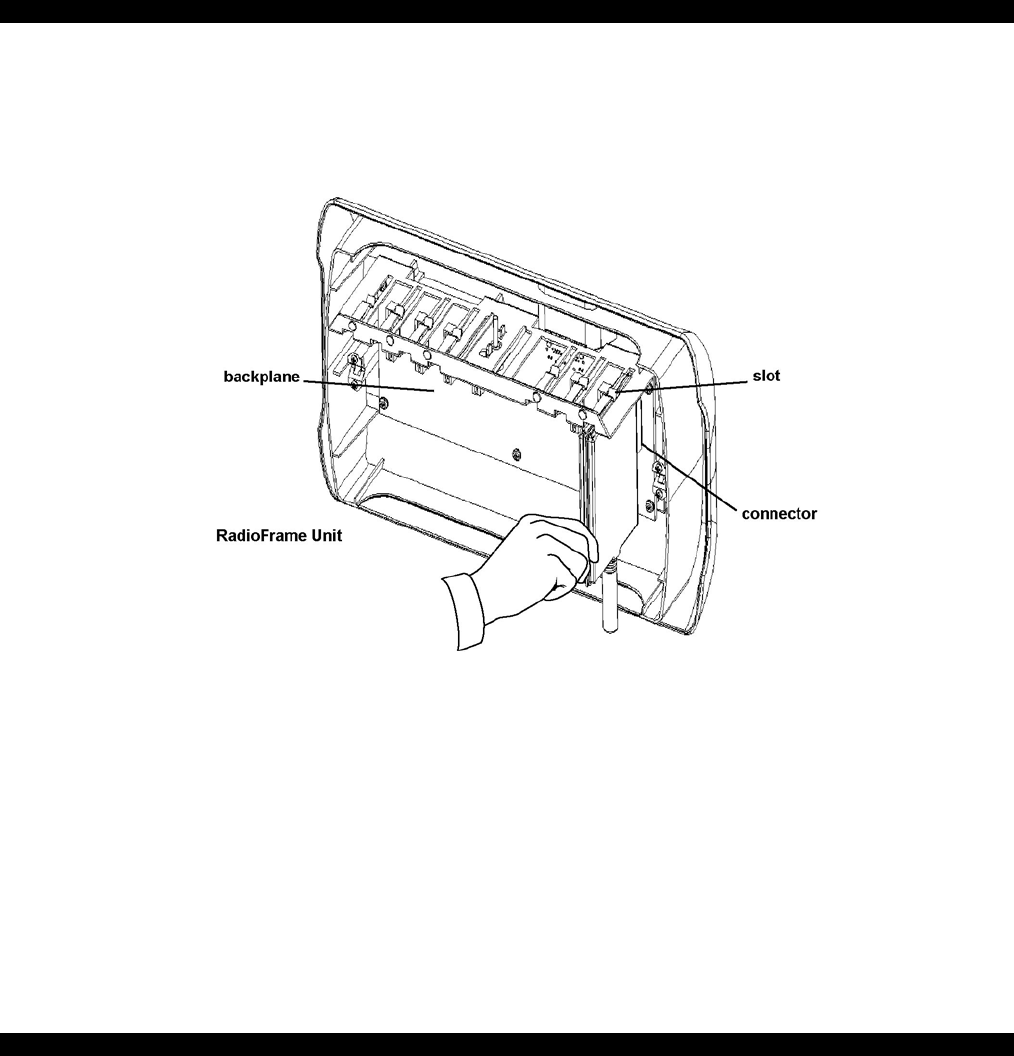
Insert the RadioBlades
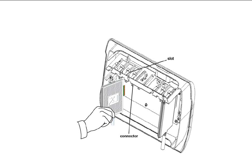
RadioBlades are shipped several to a box in individually wrapped anti-static
packaging. Each box of RadioBlades includes a disposable anti-static wrist strap
to be used when inserting the RadioBlades into the RFU. Refer to the SDS for the
exact installation location of each RadioBlade in the RFU.
1 Unwrap 30 cm (12”) of the disposable wrist strap and warp the adhesive side
around your wrist.
2 Unroll the rest of the band and remove the liner from the copper tape.
3 Attach the copper tape to the metal card cage inside the RFU.
4 Insert the RadioBlades, one at a time, into the specified slots (1 through 7) in the
RFU until the connector on each RadioBlade seats firmly into the back of the
RFU.
Installing the RadioFrame System
22
5 Remove the anti-static wrist strap and place the front cover on the RFU.
Figure 13 Slide each RadioBlade into the specified slot in the RFU.
Verify the System
During the installation, each component of the system is verified for power and
connectivity. Assuming that each system component—NCU, ACU, and RFU—
has been properly installed and is receiving power, double check that all Power,
Status, Link and Activity LEDs throughout the system are lit and are green
(Activity LEDs on all RJ45 ports should be blinking rapidly). For any other
condition on any system component or connection, refer to “Troubleshooting.” If
necessary, refer to “About This Guide: Obtaining Service and Support.”

Installing the RadioFrame System
23
Connect the RFS to the iSC
If the RFS is to be operated in an iDEN configuration, the NCU must be
connected to a Motorola integrated Site Controller (iSC). Depending on the
system configuration, the RFS will obtain its timing either from the iSC or from a
direct connection from the NCU to the building’s GPS antenna.
Connect the NCU to the iSC
The iSC is available in two models: iSCII and iSCIII. Complete the appropriate
procedure, “Connect the NCU to the iSCII” or “Connect the NCU to the iSCII”.
Connecting the NCU to an iSCII
When connecting the NCU to an iSCII, an Ethernet Media Converter must be
installed between the iSCII and the NCU. The Ethernet Media Converter is
shipped in its own container with all the cables necessary to install it.
1 Lay or mount the Ethernet Media Converter on any flat surface and plug it into
an approved power source (see the following illustration).
2 Set the Terminator switch on the front of the Ethernet Media Converter to “On”
and set the MDI switch to “MDI-X”.
3 Connect Port 1 on the front of the NCU to the 10BaseT port (RJ45) on the
Ethernet Media Converter using the provided straight-through CAT 5 cable.
4 Connect the ELP slot on the back of the iSC to the 10Base2 port (BNC) on the
Ethernet Media Converter using the provided 10Base2 cable (50 ohm coaxial
cable with two male BNC connectors).
Installing the RadioFrame System
24
Figure 14 When connecting the RFS to an iSCII, an Ethernet Media
Converter is required to connect the NCU to the iSCII.
Connecting the NCU to an iSCIII
1 Insert one end of the provided 50 ohm coaxial cable (with two male BNC
connectors) into one of the three 10Base2 ports on the back of the iSCIII (port to
be determined by Nextel).
2 Insert the other end of the cable into the 5MHz/1PPS IN port (BNC) on the back
of the NCU.
Connect the NCU to the Timing Source
If the NCU and iSC are mounted in the same location (the same building site),
the iSC will provide timing to the NCU. However, if the NCU and iSC are
located at different sites, the NCU derives its timing from the GPS antenna.

Installing the RadioFrame System
25
1 Choose one:
If the NCU and iSC are… Then…
located in the same
building
f
or an iSCI
I
, connect the NCU to the SRI card on the back of
the iSCII using the provided 1 meter, 50 ohm coaxial cable
with two male BNC connectors:
1. Connect one end of the cable to the 5MHz/1PPS “IN”
port on the back of the NCU (see the following
illustration).
2. Connect the other end of the cable to either BNC
“OUT” port of the SRI slot on the back of the iSC.
f
or an iSCII
I
, connect the NCU to the iSCIII using the
provided 1 meter, 50 ohm coaxial cable with two male BNC
connectors:
3. Connect one end of the cable to the 5MHz/1PPS “IN”
port on the back of the NCU (see the following
illustration).
4. Connect the other end of the cable to one of the three
5MHz/1PPS “OUT” ports on the back of the iSC. The
port will be determined by Nextel.
located at different
building sites
the NCU derives its timing from a GPS receiver inside the
NCU, which requires a connection to the building’s GPS
antenna:
1. Insert the GPS antenna cable into the SMB port on the
back of the NCU.
Installing the RadioFrame System
26
Figure 15 The RFS receives its timing via the iSC or the NCU.

27
3
Troubleshooting
This section describes troubleshooting information for each component of the
RadioFrame System: Network Chassis Unit, Airlink Chassis Unit, and
RadioFrame Unit. If the provided solutions do not resolve the problem, contact
Customer Support:
Telephone (425) 883-2088
Website www.radioframenetworks.com
E-mail customersupport@radioframenetworks.com
For service and support of a RadioFrame System purchased from a reseller,
contact the reseller.

Troubleshooting
28
Network Chassis Unit
The front of the Network Chassis Unit (NCU) contains eight RJ45 ports and one
EIA-232 9-pin serial port. The back of the NCU has eight RJ45 ports, two BNC
ports, and an SMB port. Each port is described in the following table.
NCU front ports Description
RJ45 Port 1 iSC—iDEN installations only
RJ45 Port 2 Ethernet LAN—network installations only
RJ45 Ports 3-8 additional Ethernet LANs
EIA-232 9-pin serial port for debugging—Customer Service Representative use only
NCU back ports
RJ45 Ports 1-8 ACUs—up to 8 ACUs may be connected to the NCU
5MHz/1PPs IN BNC connector for timing interface
5MHz/1PPs OUT BNC connector for timing interface
GPS ANT GPS antenna connection
Each card installed in the front and back of the NCU has two LEDs: Power (top)
indicates power, and Status (lower) indicates the status of the card. Each RJ45
port has two LEDs: Link (right) indicates Ethernet connectivity, and Activity

Troubleshooting
29
(left) blinks to indicate Ethernet activity. All LEDs should light as green. For all
other conditions, refer to the following table.
Indication Possible Cause What to Do
Power and Status LEDs
for cards installed in
front or back of NCU
are not lit
no power to NCU • Verify that the power cord is
installed and properly seated.
• Verify that the power source is
operational.
• Contact Customer Support.
Status LED is red—top
front card only
timing source not
available
• Connect the timing source. In
iDEN installations, this is usually
the iSC. In some cases, the timing
source is the GPS antenna.
• If the timing source is connected,
check all connections.
failed initialization
• Reboot the system: unplug the
NCU, and plug it in again. Boot
up may take several minutes.
fan is not working • Verify that the fan is operational.
• If the fan is not working, unplug
the NCU and contact Customer
Support.
Status LED is red—any
card
card is not operational • Remove and reseat card.
• Contact Customer Support for a
replacement card.

Troubleshooting
30
Indication Possible Cause What to Do
RJ45 port Link and
Activity LEDs are not
lit, or the Activity LED
is not blinking
connection is not being
made between RFS
components
• For the affected port, verify that
all cabling between components
is properly connected:
NCU front
Port 1 iSC
Port 2 Ethernet LAN (WLAN)
Ports 3-8 additional WLANs
NCU back
Ports 1-8 ACUs
Airlink Chassis Unit
The front of the Airlink Chassis Unit (ACU) contains eight RJ45 ports and one
EIA-232 9-pin serial port. The back of the ACU has eight RJ45 ports. Each port is
described in the following table.
ACU front ports Description
RJ45 Port 1 NCU—connects the ACU to the NCU
RJ45 Ports 2-8 not currently used
EIA-232 9-pin serial port for debugging—Customer Service Representative use only

Troubleshooting
31
ACU back ports
RJ45 Ports 1-8 RFUs—up to 8 RFUs may be connected to the ACU
5MHz/1PPs IN not currently used
5MHz/1PPs OUT not currently used
GPS ANT not currently used
Each card installed in the front and back of the ACU has two LEDs: Power (top)
indicates power, and Status (lower) indicates the status of the card. Each RJ45
port has two LEDs: Link (right) indicates Ethernet connectivity, and Activity
(left) blinks to indicate Ethernet activity. All LEDs should light as green. For all
other conditions, refer to the following table.
Indication Possible Cause What to Do
Power or Status LEDs
for cards installed in
front or back of ACU
are not lit
no power to ACU • Verify that the power cord is
installed and properly seated.
• Verify that the power source is
operational.
• Contact Customer Support.
Status LED is red—any
card
card is not operational • Remove and reseat card.
• Contact Customer Support for a
replacement card.

Troubleshooting
32
Indication Possible Cause What to Do
failed initialization
• Reboot the system: unplug the
ACU, and plug it in again. Boot
up may take several minutes.
fan is not working • Verify that the fan is operational.
• If the fan is not working, unplug
the ACU and contact Customer
Support.
RJ45 port Link and
Activity LEDs are not
lit, or the Activity LED
is not blinking
connection is not being
made between RFS
components
• For the affected port, verify that
all cabling between components
is properly connected:
ACU front
Port 1 NCU
Ports 2-8 not currently used
ACU back
Ports 1-8 RFUs
RadioFrame Unit
The RadioFrame Unit, or RFU, has two RJ45 ports on the top of the back cover of
the unit: MAIN and AUX. Only the MAIN port is used. The AUX port has a
protective cover that must not be removed. During installation, ensure that the
RFU is receiving connectivity from the ACU before inserting RadioBlades into
the RFU or placing the front cover on the RFU.

Troubleshooting
33
Warning!
Do not remove the protective cover from the AUX port or insert a connector
into the AUX port. This will cause damage to the RFU, the ACU, or both.
The MAIN port has two LEDs: Link (right) indicates Ethernet connectivity, and
Activity (left) blinks to indicate Ethernet activity between the RFU and the ACU.
For all other conditions, refer to the following table.
Indication Possible Cause What to Do
Port LEDs do not light connection is not being
made between the RFU
and the ACU
• Verify that all cabling between
the ACU and the RFU is
properly connected.
• Verify that the ACU is powered
on.
• Contact Customer Support.

34
Glossary
ACU
Airlink Chassis Unit—Provides the baseband
airlink processing for up to 8 RFUs, providing a
coverage span up to 250,000 square feet, and is the
interface between the RFUs and the NCU.
iSC integrated Site Controller—Motorola’s proprietary
equipment required for all iDEN installations.
iDEN integrated Digital Enhanced Network—Motorola’s
proprietary digital technology that combines the
capabilities of a standard analog dispatch system
with that of a cellular interconnect system. iDEN
uses an advanced proprietary modulation
technology consisting of a speech compression
scheme enabling three or six communication paths
over a single 25 kHz RF channel.
GPS antenna global positioning system antenna—A system that
uses geostationary satellites to triangulate the
position of a GPS receiver located on the face of the
earth.
LAN local area network—A group of computers
connected together within a building or campus.
NCU Network Chassis Unit—The main controller of the
RFS, providing external network interfaces and the
baseband network processing for the associated
ACUs and RFUs. Also, the NCU is the interface
between the RFS and the telecommunications
switching entities.

Glossary
35
RFS RadioFrame System—A configurable indoor
wireless system capable of supporting multiple air
interfaces simultaneously.
RFU RadioFrame Unit—The access interface between
signals received from mobile terminals, via a
standard air interface, and the airlink processing
performed in the ACU.
SDS Site Design Specification—A set of documentation
provided by RadioFrame Networks specifying the
design, layout, and installation requirements of a
RadioFrame System.
WLAN wireless LAN—802.11 Ethernet wireless local area
network.

36
Hardware Specifications
Network Chassis Unit/Airlink Chassis Unit
Operating Environment
• Operating Ambient Temperature: 0oC to +40oC (+32oF to +104oF)
• Storage Temperature: -40oC to +70oC (-40oF to +158oF)
• Relative Humidity: 10-90% non condensing
• Altitude: -200 to +8000 feet above mean sea level; above 8000', reduce
maximum operating ambient temperature by 2oC per 1000' to a maximum of
13000'
• Shock: 40 g’s
• Vibration: Level 3 earthquake
• Keep product free from dust, wind, salt, liquids
Agency Compliance
FCC Class A CSA 22.2 No. 60950
ISTA 2A transit
Physical Specifications
• Dimensions: 19" wide x 7" high x 13" deep (approx.)
• Weight: 15 lbs (approx., no cards)
Input Power
• 100-240 Volts AC, 47-63 Hz, 8-3.5A, or
Cabling Pinouts
• For 120VAC power, use the power cord provided (use of a different cord may
void the warranty and/or cause electrical fire and damage).

Hardware Specifications
37
RadioFrame Unit
Certified to 47 CFR Part 90. Licensed operation required. Radiofrequency
exposure approved for fixed installations only. The antenna used for this
transmitter is integral to the unit. The radio and its associated antenna are to be
fixed-mounted on indoor permanent structures providing a separation distance
of at least 20 cm from all persons during normal operation and 10 feet from other
RFU mounted assemblies. The maximum radiated output power at the antenna
must satisfy the MPE Categorical Exclusion Requirements of 2.1091. The
maximum radiated output power of any antenna shall not exceed 100mW. RF
exposure compliance may need to be addressed at the time of licensing, as
required by the responsible FCC Bureau(s), including antenna co-location
requirements of 1.1307(b)(3).
Operating Environment
• Operating Ambient Temperature: 0oC to +40oC (+32oF to +104oF)
• Storage Temperature: -40oC to +70oC (-40oF to +158oF)
• Relative Humidity: 10-90% non condensing
• Altitude: -200 to +8000 feet above mean sea level; above 8000', reduce
maximum operating ambient temperature by 2oC per 1000' to a maximum of
13000'
• Shock: 40 g’s
• Vibration: Level 3 earthquake
• Keep product free from dust, wind, salt, liquids
Agency Compliance
FCC Part 90 CSA 22.2 No. 60950
ISTA 2A transit
Physical Specifications
• Dimensions: 13.5" wide x 8" high x 5" deep (approx.)
• Weight: 3 lbs (approx., no cards)
Input Power
• Negative 36-56 Volts DC, 0.8A

38
Index
ACU. See Airlink Chassis Unit
Airlink Chassis Unit
connecting to RFUs, 17
connecting to the NCU, 17
defined, 3
installing, 15
LEDs, 16, 31
mounting, 15
ports, 30
specifications, 36
troubleshooting, 30
unpacking, 15
cabling requirements, 11
customer support, vi, 27
EMC. See Ethernet Media Converter
Ethernet Media Converter, installing, 23
GPS antenna
connecting to the iSC, 24
connecting to the NCU, 24
defined, 34
iDEN. See integrated Digital Enhanced
Network
installation locations, identifying, 11
integrated Digital Enhanced Network, 23, 34
integrated Site Controller. See iSC
iSC
connecting to the NCU, 23
defined, 23, 34
labeling wiring, 12
LEDs
ACU, 16, 31
NCU, 13, 16, 28
RFU, 20, 33
NCU. See Network Chassis Unit
Network Chassis Unit
connecting to ACUs, 14
connecting to the EMC, 23
connecting to the GPS antenna, 24
connecting to the iSC, 23
defined, 3
installing, 12
LEDs, 13, 16, 28
mounting, 13
ports, 28
specifications, 36
troubleshooting, 28
unpacking, 13
RadioBlades
defined, 4
inserting into the RFU, 21
installation locations of, 21
unpacking, 21
RadioFrame System
defined, 1
unpacking, 12
verifying the installation, 22
RadioFrame Unit
connecting to the ACU, 20
defined, 4
inserting RadioBlades, 21
installing, 18
LEDs, 20, 33
mounting on a wall, 18
mounting on or above the ceiling, 19

Index
39
port, 20
specifications, 37
troubleshooting, 32
unpacking, 18
RFS. See RadioFrame System
RFU. See RadioFrame Unit
safety precautions, 5
preventing electrostatic discharge
damamge, 9
safety recommendations, 5
safety warnings, 6
safety with electricity, 8
SDS. See Site Design Specification
service and support, vi
Site Design Specification
defined, 11
RFS installation location, 11
wiring locations, 12
tools and parts required, 5
troubleshooting
ACU, 30
NCU, 28
RFU, 32
unpacking the RFS, 12
verifying the installation, 22
wiring
labeling, 12
locations of, 12
testing, 12