RadioFrame Networks SSERIESGSMNA02 S -BTS GSM Base Station User Manual Users manual
RadioFrame Networks, Inc S -BTS GSM Base Station Users manual
Users manual

User Reference
S-Series GSM/GPRS Radio Base Station
931-1002-01 Rev. A

Service Information
This equipment complies with part 15 of the FCC Rules. Operation is subject to the two following conditions:
This device may not cause harmful interference, and this device must accept any interference received,
including interference that may cause undesired operation. This equipment has been tested and found to
comply with the limits pursuant to 47 CFR Part 22 subpart H and Part 24 Subpart E of the FCC Rules. These
limits are designed to provide reasonable protection against harmful interference when the equipment is
operated in a commercial environment.
Notices
RadioFrame Networks reserves the right to revise this document for any reason, including, but not limited to,
conformity with standards promulgated by various governmental or regulatory agencies, utilization of advances
in the state of the technical arts, or to reflect changes in the design of equipment, techniques, or procedures
described or referred to herein.
Liability to anyone arising out of use or reliance upon any information set forth herein is expressly disclaimed,
and no representation or warranties, expressed or implied, are made with respect to the accuracy or utility of
any information set forth herein.
Copyrights and Trademarks
RadioFrame Networks is a trademark or service mark, and RadioFrame and the RadioFrame Networks logo
are registered trademarks of RadioFrame Networks, Inc. All other trademarks and trade names are the
property of their respective owners.
S-Series GSM/GPRS Radio Base Station
© Copyright 2006 RadioFrame Networks, Inc. All Rights Reserved.
ii S-Series GSM/GPRS Radio Base Station RadioFrame Networks, Inc.
RadioFrame Networks, Inc.
9461 Willows Road NE, Suite 100
Redmond, WA 98052
USA
Tel: +1-1-425-278-2780
Fax: +1-1-425-278-2781
www.radioframenetworks.com

RadioFrame Networks, Inc. S-Series GSM/GPRS Radio Base Station iii
Table of Contents
1 Getting to Know Your Radio Base Station 5
2 Minimum Requirements Error! Bookmark not defined.
3 The S1 Indicators, Connectors and Reset Button 6
4 Connecting the S1 7
5 Configuring the S1 Router 9
Appendix A Troubleshooting 16
Figures
Figure 1 Front Indicators 6
Figure 2 Back Connectors and the Reset Button 6
Figure 3 Typical Setup 7
Figure 4 S1 Connections 8
Figure 5 S1 Router Login 9
Figure 6 Sample Automatic Setup Performed 10
Figure 7 DHCP Server Setup 11
Figure 8 Advanced Routing 12
Figure 9 Firewall: Add Rule 13
Figure 10 Port Range Forwarding 14
Figure 11 Status Screen 15
Tables
Table 1 Status Screen and S1 Factory Defaults 15

4 S-Series GSM/GPRS Radio Base Station RadioFrame Networks, Inc.
CAUTION: Safety Instructions
Read and follow these instructions when connecting and using your base station.
• Maintain a distance of at least 20 cm between persons and a functioning radio
base station.
• Do not store or use the radio base station in locations that are exposed to heat,
direct sunlight, excessive dust, or extreme cold. Keep it away from heaters,
stoves, fireplaces, and other sources of heat.
• Only a qualified technician should open the radio base station case. Do not
insert anything into the case openings or touch the inside of the case to avoid
damage.
• Do not expose the radio base station to liquids. You may dust the base station
with a damp cloth occasionally, being sure not to allow moisture to get inside.
• Always be sure that your base station power transformer is rated for the AC
power available in your location.
• Locate the radio base station near an accessible electrical outlet. Ensure that
power and data cables are not located where they can be stepped on or tripped
over. If the power cable has been damaged, do not use it. When connecting and
disconnecting cables, be sure to grasp the plug and not the cable. Be careful to
pinch the locking clip when disconnecting any Ethernet cable.
• Openings in the radio base station case are provided for ventilation. To prevent
overheating, these openings must not be blocked or covered. Do not locate the
base station on a soft surface such as a blanket because doing so may block
the openings on the bottom of the case. If you place the base station in a
bookcase or other enclosed space, be sure to provide adequate ventilation and
air flow.
Regulatory Notices
Electromagnetic Interference (EMI) is any signal or emission, radiated in free space or
conducted along power or signal leads, that endanger the function of a radio
navigation or other safety service or seriously degrades, obstructs, or repeatedly
interrupts a licensed radio communications service. Radio Communications services
include but are not limited to AM/FM commercial broadcast,
CE Notice
<<To Be Supplied>>

RadioFrame Networks, Inc. S-Series GSM/GPRS Radio Base Station 5
1 Getting to Know Your Radio Base Station
Welcome
The S1 GSM/GPRS Radio Base Station is the link between your cell phone (or your
data card) and your service provider, providing your own personal island of coverage.
It has a network connection for Internet access through your cable or DSL modem.
There’s also a router inside and four LAN (local area network) ports for sharing
connectivity with multiple computers.
To create your cell radio link, install and set up the base station. You won’t find a
complicated configuration script because the base station finds your cell service
provider across the Internet by itself! (This assumes, of course that your cable or DSL
modem is “talking” to its ISP, or Internet service provider. Please make sure this step
is taken before you attempt to get the S1 base station working; you will need to
arrange service and make sure it is working by contacting the ISP or your cellular
service provider.)
Once you have confirmed Internet access through your cable or DSL modem, the
Quick Install Guide gives you all the information you need to get on the air. This
reference contains much more information in case, for example, you want to do
special configuration of the base station’s router. By the way, we don’t recommend
manually setting up the router (or the radio base station for that matter) unless you
have unusual needs AND you have the experience to work with Internet Protocol (IP)
communications devices. Chances are the S1 works just the way you need, right out
of the box!
Speaking of the box . . .
Inside the S1 GSM/GPRS Radio Base Station box, you will find:
• S1 Radio Base Station, GSM/GPRS
• Power adapter
• Ethernet cable (CAT5)
• Quick Install Guide
• Warranty Card
You will also need . . .
• Broadband connection and cable or DSL modem
• For web-based configuration, a computer running Microsoft Windows with:
Ethernet network adapter and cable
Internet Explorer 5.0 or Mozilla Firefox 1.5
6 S-Series GSM/GPRS Radio Base Station RadioFrame Networks, Inc.
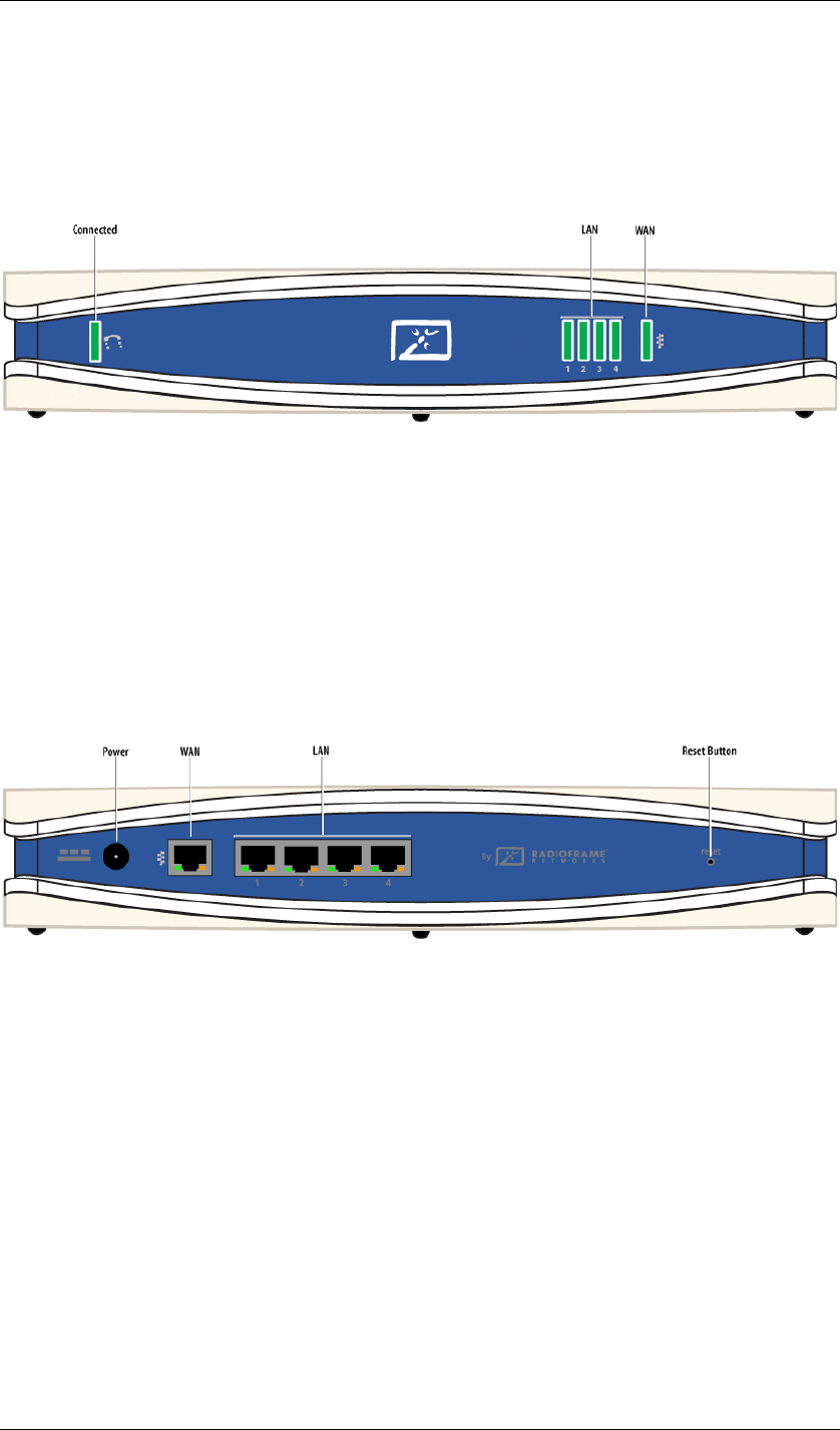
2 The S1 Indicators, Connectors and Reset Button
S1 LEDs are located on the front panel, shown in Figure 1, and connectors and the reset
button are located on the back panel, shown in Figure 2.
Figure 1 Front Indicators
Indicators
Connected Indicator Green. Lights when the S1 detects a valid cell
communication channel.
LAN Indicators Green. The LAN indicators serve two purposes. When the light is
steadily ON, it indicates that the S1 router is connected to an Ethernet device through
the corresponding LAN port. When the light is flashing, the router is sending or
receiving data over that port.
WAN Indicators Green. The WAN indicator serves two purposes. When the light is
steadily ON, it indicates that the S1 router is connected to a cable or DSL modem.
When the light is flashing, the router is sending or receiving data over the WAN port.
Figure 2 Back Connectors and the Reset Button
Connectors
Power Connector The power connector is where you connect the power adapter.
LAN Ports The LAN ports connect to devices, such as computers or print servers,
using a CAT5 (or better) Ethernet cable.
WAN Port The WAN port connects to your cable or DSL modem using a CAT5 (or
better) Ethernet cable.
Reset Button
The Reset button reboots the S1 when you press it for just a second. If you press the
Reset button for 30 seconds, the S1 is reset to factory defaults. Router settings, such
as password, static IP addresses, and port forwarding table entries are all cleared.
Note: Resetting the S1 (as opposed to rebooting it) clears any settings, such as router
configuration and replaces them with the factory defaults. If you have made
modifications, it is a good idea to write down these settings before doing a Reset. You
can find most of them on the Status screen. (See Chapter 4.)
RadioFrame Networks, Inc. S-Series GSM/GPRS Radio Base Station 7
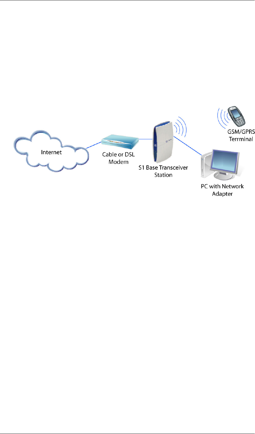
3 Connecting the S1
Your S1 connects to your broadband modem (cable or DSL). Then you can connect
networked devices, for example a computer and a printer server, to the network ports
on the S1. See Figure 3.
Note: The Internet packets for your cellular service are time-critical for smooth conversation.
Therefore the S1 gives priority to voice packets. It is important to connect the S1
directly to your broadband modem and connect other devices to the network ports on
the S1.
Figure 3 Typical Setup
Placement Tips
The S1 provides a "coverage area" within which you will be able to use your cellular
devices. Typical indoor operating range for cellular devices is between xx and yy
meters away from the S1 base station. Signal strength degrades somewhat as the
distance between your S1 and cellular devices increases. This may or may not be
noticeable to you. Some obstructions can weaken signals simply by getting in the way
of your cellular radio waves, for example, metal appliances, large mirrors, and thick
walls.
If you have concerns about your cellular coverage that might be related to range or
obstruction factors, place your S1 as close as possible to the centre of the area where
you want coverage. In a multi-storey setting, place the S1 on a floor that is as close to
the centre of the building as possible. This may mean placing the S1 in an upper
storey.
Making the Connections
Here are the steps to connecting the S1:
• Connect the S1 WAN port to the Ethernet port on the DSL or cable modem
• Connect any network devices to the LAN ports on the S1
• Connect the AC power cable to the S1
8 S-Series GSM/GPRS Radio Base Station RadioFrame Networks, Inc.
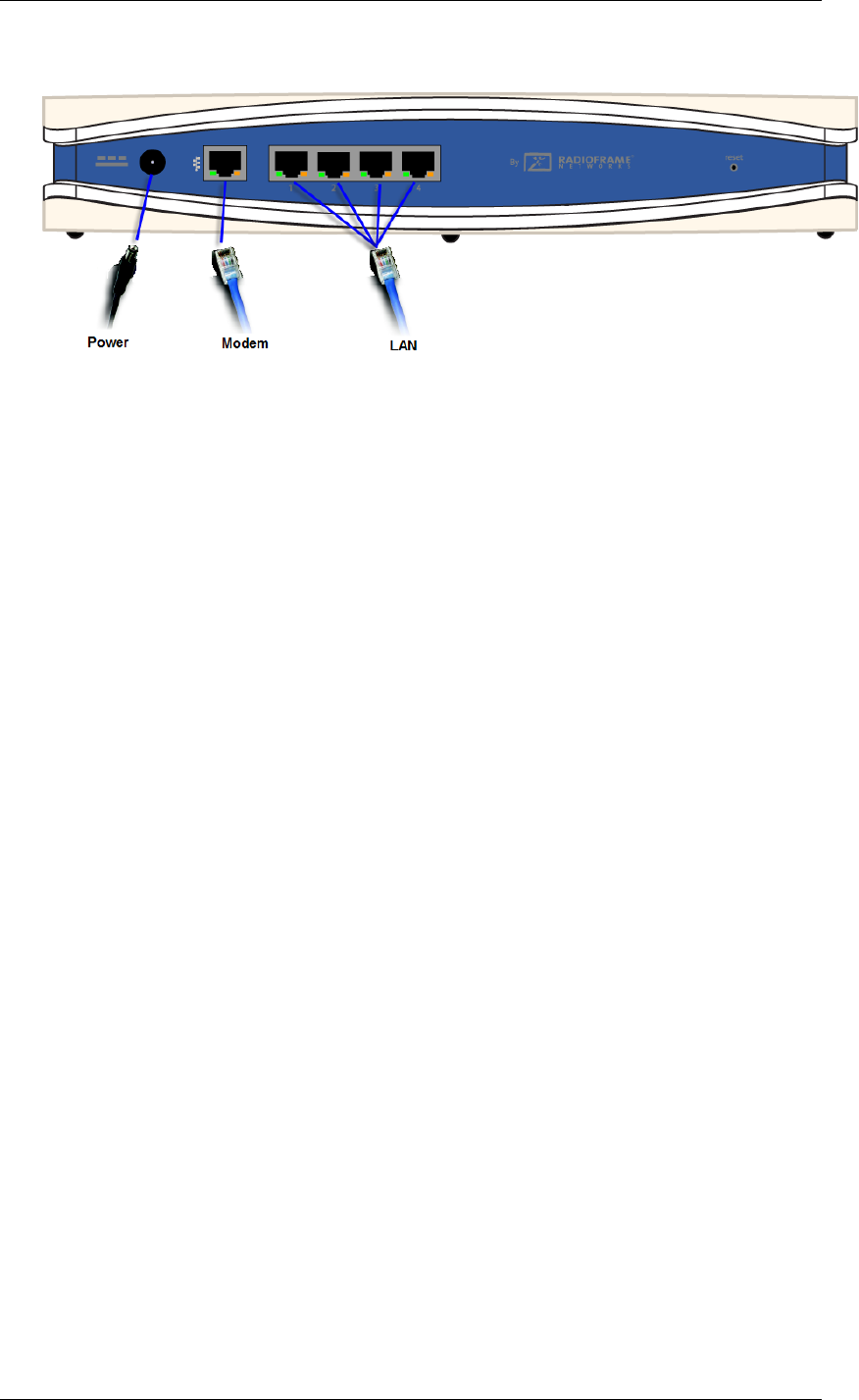
Figure 4 S1 Connections
1 Make sure that all network devices you are going to connect to the S1 are OFF. Make
sure the DSL or cable modem is OFF. Make sure the modem is properly connected to
the coax cable or telephone cable that provides your broadband Internet service.
Note: Your ISP can assist you with this connection. It requires that the ISP has
configured your Internet access and you have received any necessary setup
information from your ISP. Once you are connected, the ISP can also test the
connection from their office.
2 Connect an Ethernet network cable (CAT5 or better) to the S1 WAN (modem) port.
3 Connect the other end to your DSL or cable modem’s Ethernet port.
4 Connect Ethernet network cables to your networked devices’ ports and the LAN ports.
5 Power on the cable or DSL modem.
Note: You might wish to check the signal-strength bars on your cell phone before
powering up the S1 so that you can observe the difference once the S1 is in
service.
6 Connect the AC power adapter cable to the S1 power port and then plug the power
adapter into an electrical outlet.
7 Power on the networked devices.
Wall Mounting (Optional)
<<To Be Supplied>>
First Call
The S1 takes a few moments to register on the cellular network, but there’s no
intervention required on your part to get it working. After the initialization is complete,
you can simply make a call as you normally do.
RadioFrame Networks, Inc. S-Series GSM/GPRS Radio Base Station 9
4 Configuring the S1 Router
For the majority of situations, the router configuration does not need your attention.
The S1 uses Dynamic Host Configuration Protocol (DHCP) to find the information it
needs from your Internet Service Provider (ISP) over the Wide Area Network (WAN)
connection.
If you do wish to make router configuration changes, you can use this chapter of the
manual to see what the settings mean. (To secure the router, you will need to change
the default password.)
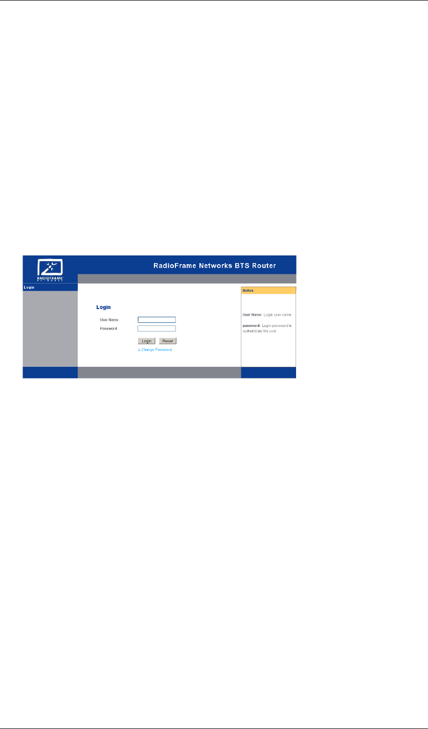
Logging Into the S1 Router
The router has its own web client for your use. For access, launch Internet Explorer or
Mozilla Firefox browser and enter the router’s IP address—192.168.1.1—in the
browser’s Address Field. Press Enter. The Login screen (Figure 5) appears. Type
admin in the User Name field and admin123 in the Password field. Click Login.
Figure 5 S1 Router Login
In Figure 6 you can see that DHCP is selected, and example settings, such as your
ISP provides, are shown in the “Internet Setup” section of the Setup screen. These
settings will be different in your case, but you don’t need to change anything because
DHCP takes care of the settings automatically.
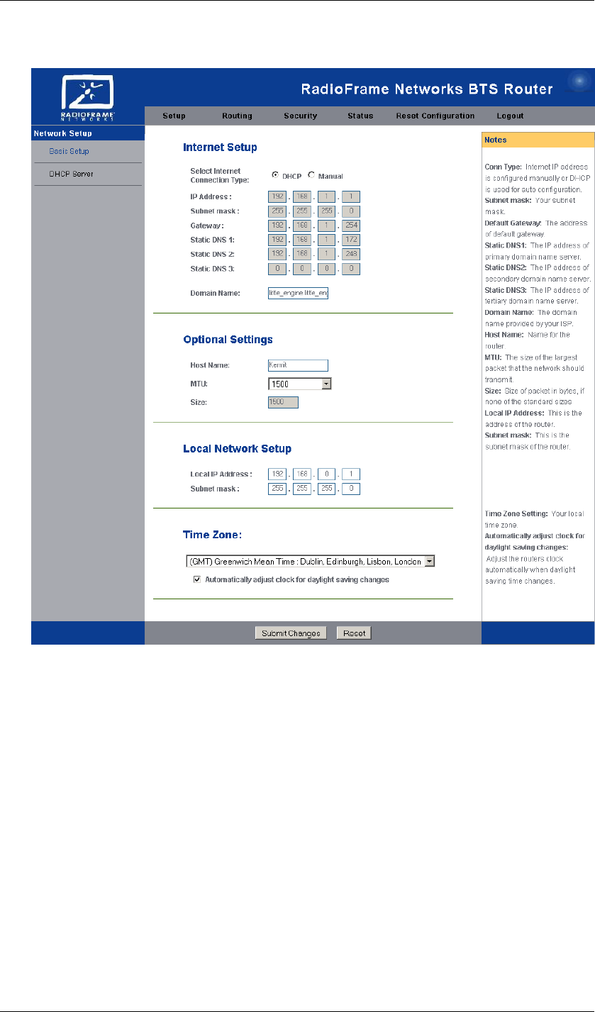
10 S-Series GSM/GPRS Radio Base Station RadioFrame Networks, Inc.
Figure 6 Sample Automatic Setup Performed
Along the top of the interface are 6 main tabs: Setup, Routing, Security, Status, Reset
Configuration, and Logout.
The Setup Tab—Basic Setup
Internet Setup By default, your ISP will provide an IP address automatically. In this
case, the DHCP radio button is selected and the fields in this section are automatically
populated.
If you select the Manual radio button, you need to obtain a static IP address and other
configuration information from your ISP and enter it in these fields.
IP Address This is the IP address of the S1 as seen from the Internet. Your ISP
will provide you with the static IP Address you need to specify here.
Subnet mask Your ISP will provide you with the Subnet Mask.
Gateway Your ISP will provide you with the default Gateway Address.
Static DNS 1-3 Your ISP will provide you with at least one Domain Name System
(DNS) Server IP Address.
Optional Settings In most cases, just leave these blank.
RadioFrame Networks, Inc. S-Series GSM/GPRS Radio Base Station 11
Host Name If your ISP asks for a host name, make one up and enter it here.
MTU The MTU (Maximum Transmission Unit) setting specifies the largest packet
size permitted for network transmission.
Size This is not editable if you leave MTU at its default.
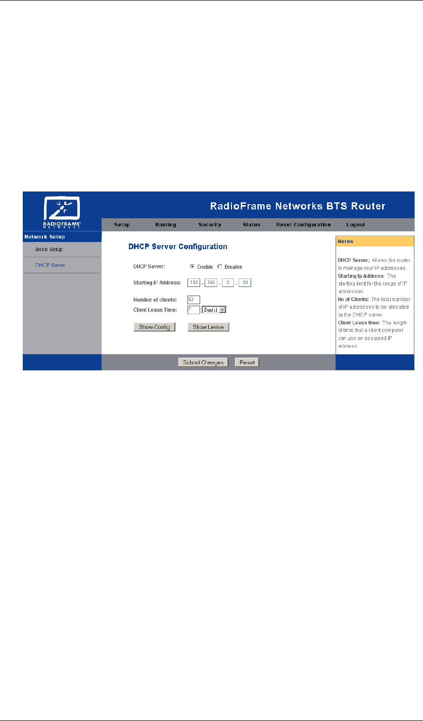
The Setup Tab—DHCP Setup
From the setup tab, if you click the DHCP Server link in the left margin, you will see
the screen shown in Figure 7. These settings allow you to configure the S1 router’s
LAN-side Dynamic Host Configuration Protocol (DHCP) server function for devices
connected to the S1 LAN ports.
Figure 7 DHCP Server Setup
DHCP Server By default, the router is enabled as a local DHCP server. If you
already have one on your network, set the option to Disable. (If you disable DHCP,
assign a LAN-side static IP address to the S1.)
Starting IP Address This address must be larger than the S1 LAN IP address and
on the same subnet. By default the Starting IP address is 192.168.0.50.
Number of Clients This is the maximum number of devices you wish the router to
be able to assign addresses.
Client Lease Time This is the amount of time before the devices will automatically
be reassigned a dynamic IP address.
Show Config button Shows a table of Starting IP Address, Number of Clients,
Client Lease Time and a delete checkbox to clear.
Show Lease button Shows a table of Host Name, MAC Address, IP Address.
When you are done setting up DHCP, click the Submit Changes button.
12 S-Series GSM/GPRS Radio Base Station RadioFrame Networks, Inc.
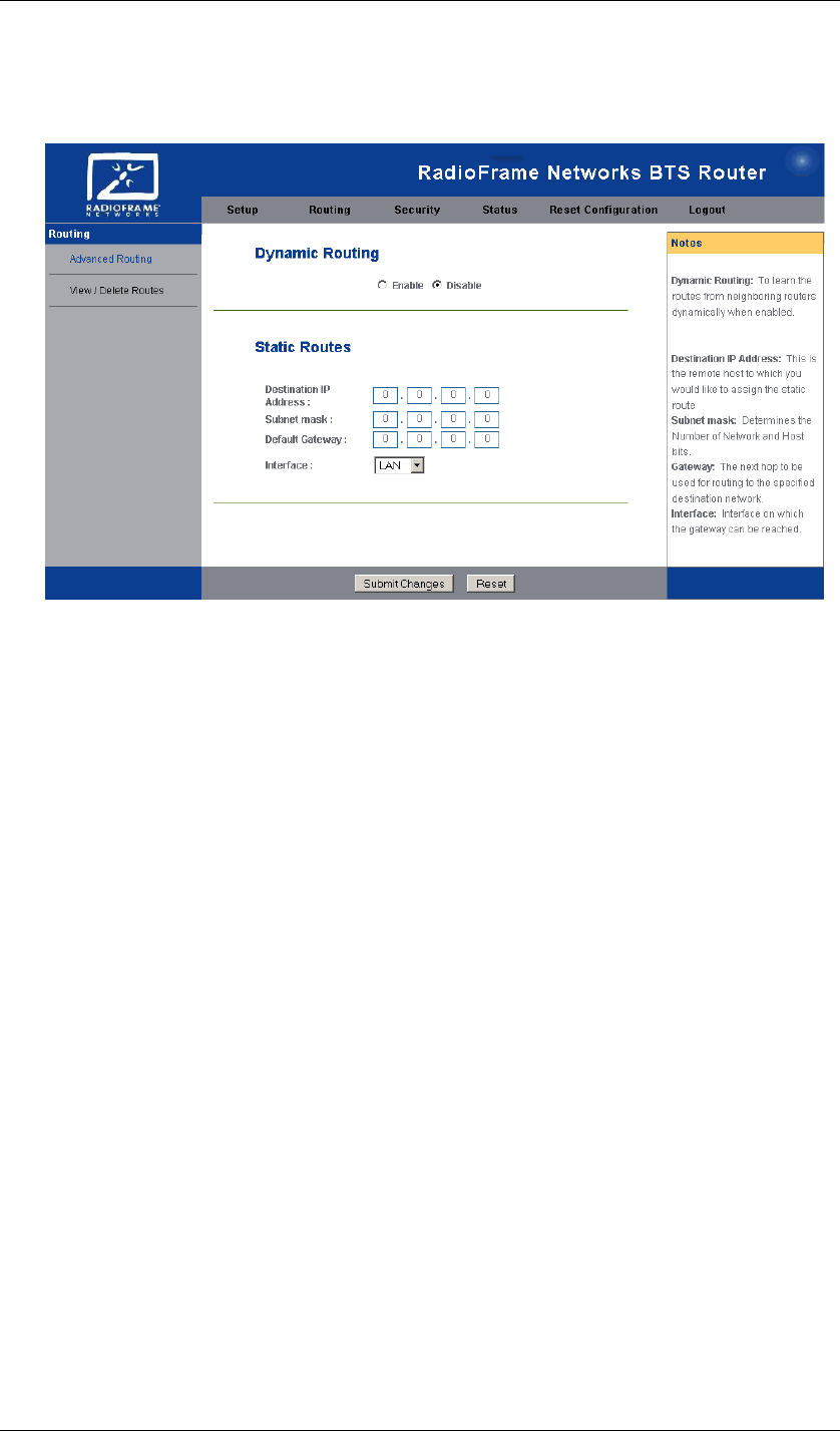
The Routing Tab—Advanced Routing
Figure 8 Advanced Routing
Dynamic Routing By default, dynamic routing is disabled. It enables the router to
determine network packets’ route based on the fewest hops between source and
destination.
Static Routes Static routes are designated routes that network packets must take
between source and destination.
Destination IP Address This is the address of the host (or network) to which
packets on the static route are directed.
Subnet Mask This is the subnet mask of the route destination.
Default Gateway This is the address of the route destination gateway.
Interface This is the port (LAN or WAN) facing the route destination.
When you are done configuring routing, click the Submit Changes button.
The Routing Tab—View/Delete Routes
Selecting the View/Delete Routes link pops up a window that shows a table of the
routes that are set up.
RadioFrame Networks, Inc. S-Series GSM/GPRS Radio Base Station 13
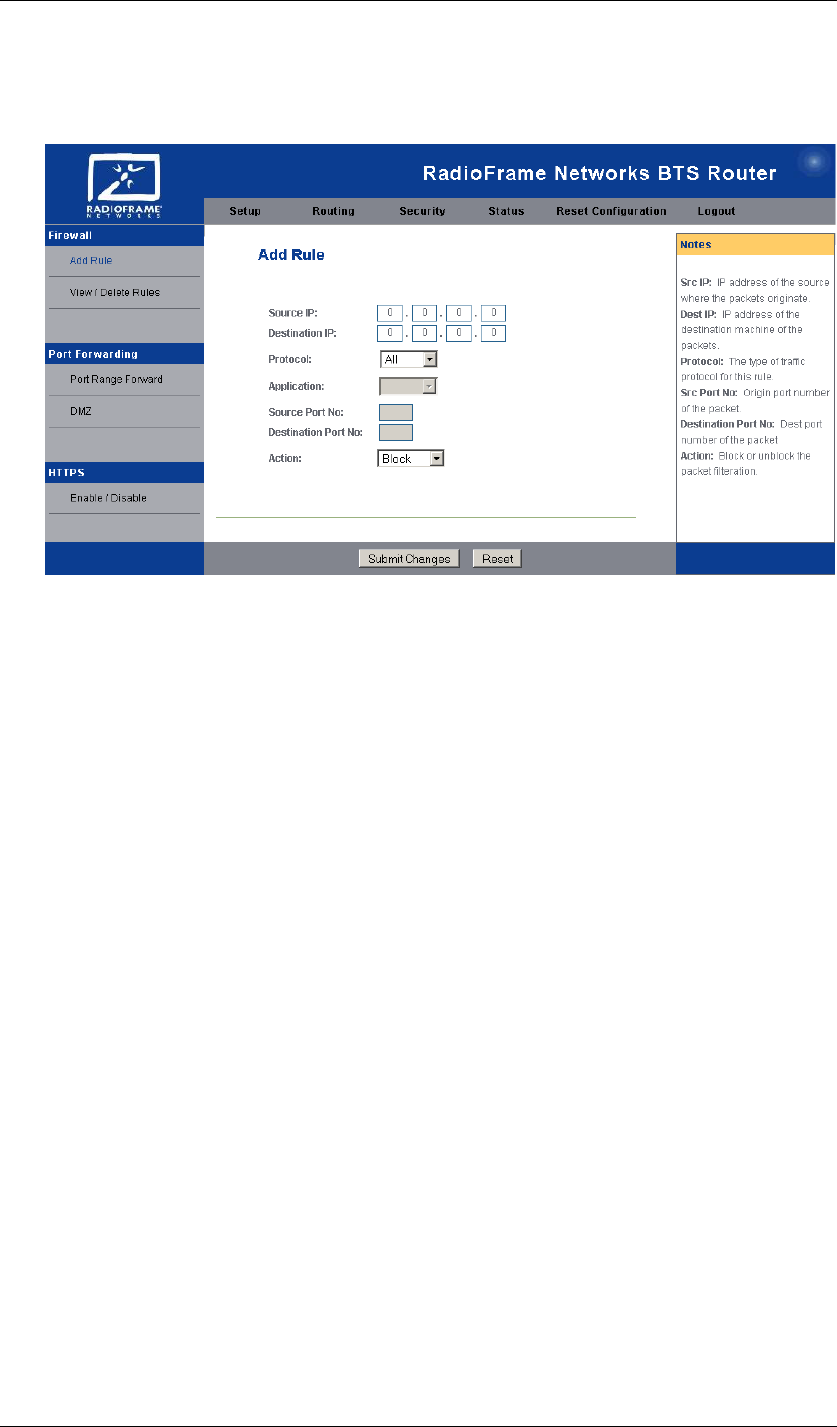
The Security Tab—Firewall
Figure 9 Firewall: Add Rule
Add Rule Use this screen to set up rules to filter Internet packets to enhance your
network’s security.
Source IP Enter the IP Address where the filtered packets originate.
Destination IP Enter the IP Address where the filtered packets are destined.
Protocol Optionally, choose a protocol for the packets you wish to filter.
Application Choose the application for the packets you wish to filter.
Source Port No This field is read-only.
Destination Port No This field is read-only.
Action Choose to block packets or not.
When you are done setting up filtering rules, click the Submit Changes button.
View/Delete Firewall Rules View/Delete Rules link pops up a window that shows a
table of the firewall rules that are set up.
14 S-Series GSM/GPRS Radio Base Station RadioFrame Networks, Inc.
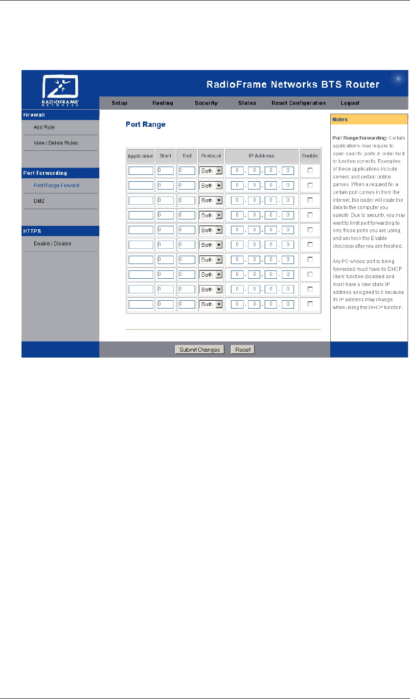
The Security Tab—Port Forwarding
Figure 10 Port Range Forwarding
Port Range Forward Use this table to allow for public services or for specialized
applications to work on your network.
Application Enter the name of the application.
Start Enter the port the server or Internet application uses.
End Enter the same port number or the upper end of the range.
Protocol Select TCP, UDP, or Both.
IP Address Enter the IP address of the server that you want the Internet users to
be able to access.
Enable checkbox Check the Enabled checkboxes to enable the services you
have defined.
When you are done setting up port forwarding, click the Submit Changes button.
The Security Tab—HTTPS Enable/Disable
This page allows you to turn on or off management of HTTPS.
The Status Tab
The Status Tab shows the current router settings in a read-only display. Figure 11
gives an example. These settings are a combination of factory defaults and changes
that have been applied. Table 1 lists the default setting for each parameter.
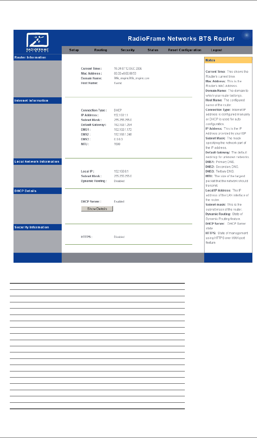
RadioFrame Networks, Inc. S-Series GSM/GPRS Radio Base Station 15
Figure 11 Status Screen
Table 1 Status Screen and S1 Factory Defaults
Setting Default
Router Information
Current Time —
Mac Address —
Domain Name —
Host Name —
Internet Information
Connection Type DHCP
IP Address 192.168.1.1
Subnet Mask 255.255.255.0
Default Gateway 192.168.1.254
DNS1, -2, -3 —
MTU —
Local Network Information
Local IP 192.168.0.1
Subnet Mask 255.255.255.0
Dynamic Routing Disabled
DHCP Details
DHCP Server Enabled
Security Information
HTTPS Disabled

16 S-Series GSM/GPRS Radio Base Station RadioFrame Networks, Inc.
Appendix A Troubleshooting
The S-Series GSM/GPRS Base Station is designed for plug and play installation and
operation. Should the base station fail to function as expected, please review these
steps in order, depending on the symptoms.
<<To Be Supplied>>