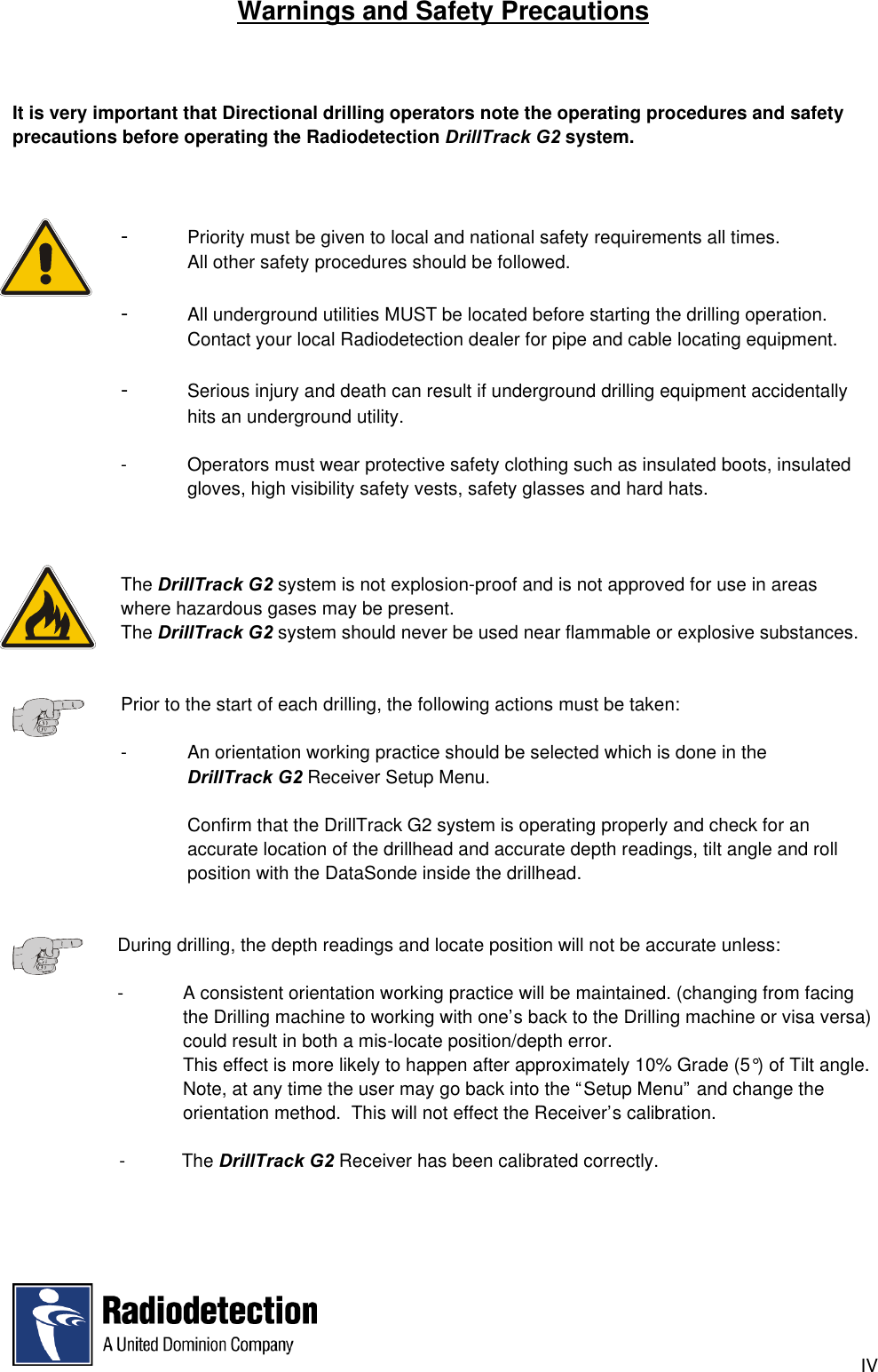
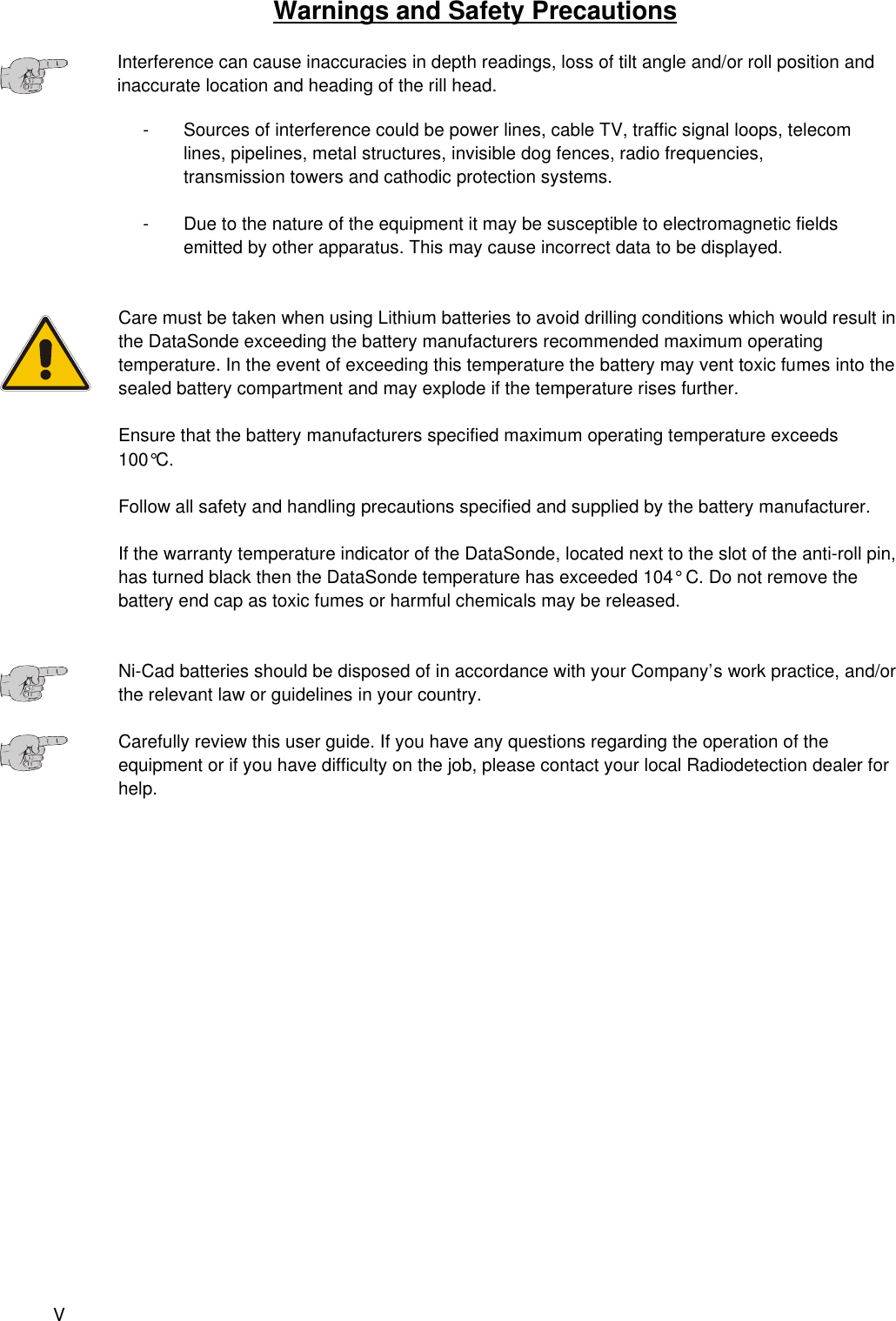
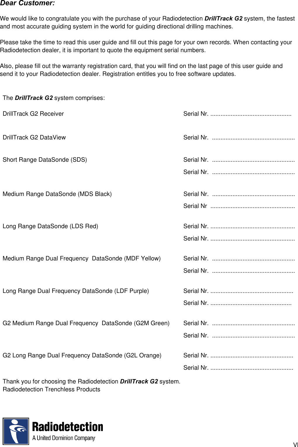
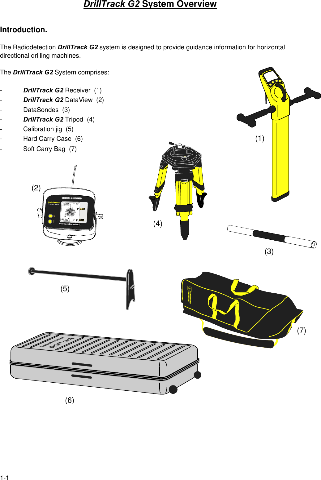
Radiodetection ND241D Low Frequency Drill Location Device User Manual DRILLTRACK

Radiodetection Ltd Low Frequency Drill Location Device DRILLTRACK

Manual

                DRILLTRACKUSER MANUALRevision 1  05.2001
IForewordIt is important that you read this user guide before operating your Radiodetection DrillTrack G2 system.This manual and all its contents are subject to change. Radiodetection products are under continuousdevelopment and are subject to change. Radiodetection Limited reserves the right to modify the productwithout notice. Some product changes may have taken place after this user guide was published.Contact your local Radiodetection dealer for the latest information on Radiodetection DrillTrack G2.Copyright © by RADIODETECTION TRENCHLESS PRODUCTS, a division of RADIODETECTION LTD.All rights reserved.The DrillTrack G2 system is covered by the following Patents: US 5,917,325; US6,107,801;GB2,330,204; EP 0,815,472; and other Patents pendingIMPORTANT NOTICERadiodetection makes every effort to ensure that all technical information, statements andrecommendations about Radiodetection Trenchless products are based on information believed to bereliable, but the accuracy or completeness thereof is not guaranteed. In no event shall Radiodetection beliable for any loss, inconvenience, damage or problems caused through use of the equipment.Before utilizing the product, the user should determine the suitability of the product for its intended use.The user assumes all risks and liability whatsoever in connection with such use.COMPLIANCE STATEMENTWhen used in accordance with the user manual, relevant parts of this product comply with ‘TheRadio Equipment and Telecommunications Terminal Equipment Directive’ (1999/5/EC) and/or EMCDirective (89/336/EEC) for use in a residential, commercial and light industry environment, asrequired.As appropriate, this equipment complies with the following:-FCC Part 90FCC Part 15EN 300 220-3EN 300 330EN 301 489-3Appropriate radio transmissions from the equipment have been certified by the FCC.  The followingFCC IDs apply:E86DTR100: K68ND2415A; K68ND2415B; K68ND2415C; K68ND2415DThis product must only be used with the antennas supplied with it.  This product must not beconnected to the mains supply, either directly or indirectly via an adaptor or battery eliminator.  Suchconnection, use with other antenna or any changes, or modifications made to this product notexpressly approved by Radiodetection Ltd could void the user's authority to operate the equipment.
llNote: Appropriate parts of this equipment have been tested and found to comply with the limits for aClass B digital device, pursuant to part 15 of the FCC Rules.  These limits are designed to providereasonable protection in a residential installation.  This equipment generates, uses, and can radiateradio frequency energy and, if not installed and used in accordance with the instruction manual, maycause harmful interference to radio communications.  However, there is no guarantee thatinterference will not occur in a particular installation.  If this equipment does cause harmfulinterference to radio or television reception, which can be determined by turning the equipment offand on, the user is encouraged to correct the interference by one or more of the following measures:- reorient or relocate the receiving antenna.- Increase the separation between the equipment and receiver.- Connect the equipment into an outlet on a circuit different from that to which the receiver  is connected.- Consult the dealer or an experienced radio/TV technician for help.All DrillTrack G2 units are weatherproof to NEMA 3R and IP54All DrillTrack G2 units are shock and vibration tested to IEC68All DrillTrack G2 units are manufactured according to the International Quality Norm ISO 9001
lIITable of ContentsForeword  IWarnings and Safety Precautions III(1) DrillTrack G2 System OverviewIntroduction 1-1Features of DrillTrack G2 Receiver and DataView 1-2(2) DataSondeThe Radiodetection DataSondes 2-1Powersave Modes 2-3Overheat Warning 2-3DataSonde Magnetic Field 2-4Dual Frequency DataSonde change method 2-4(3) DrillTrack G2 AccessoriesDrillTrack G2 Tripod 3-1Calibration Jig 3-1Hard carry case 3-2Soft carry bag 3-2(4) DrillTrack G2 Function keysReceiver 4-1DataView 4-2(5) DrillTrack G2 Operating InstructionsBefore starting 5-1How to setup the DrillTrack G2 Receiver 5-1Calibration of the DrillTrack G2 Receiver 5-6Tilt angle compensation 5-7Borelogger 5-8Locating 5-9Steering 5-12High Temperature Alarm 5-14(6) DrillTrack G2 DataViewDataView information 6-1Remote Steering 6-1(7) Tips and TricksTroubleshooting Guide 7-1Angle conversion table 7-3WarrantyRegistration Card
IVWarnings and Safety PrecautionsIt is very important that Directional drilling operators note the operating procedures and safetyprecautions before operating the Radiodetection DrillTrack G2 system.-Priority must be given to local and national safety requirements all times.All other safety procedures should be followed.-All underground utilities MUST be located before starting the drilling operation.Contact your local Radiodetection dealer for pipe and cable locating equipment.-Serious injury and death can result if underground drilling equipment accidentally hits an underground utility.- Operators must wear protective safety clothing such as insulated boots, insulated gloves, high visibility safety vests, safety glasses and hard hats.The DrillTrack G2 system is not explosion-proof and is not approved for use in areas where hazardous gases may be present.The DrillTrack G2 system should never be used near flammable or explosive substances.Prior to the start of each drilling, the following actions must be taken:- An orientation working practice should be selected which is done in theDrillTrack G2 Receiver Setup Menu.Confirm that the DrillTrack G2 system is operating properly and check for anaccurate location of the drillhead and accurate depth readings, tilt angle and rollposition with the DataSonde inside the drillhead.During drilling, the depth readings and locate position will not be accurate unless:-   A consistent orientation working practice will be maintained. (changing from facingthe Drilling machine to working with one’s back to the Drilling machine or visa versa)could result in both a mis-locate position/depth error.This effect is more likely to happen after approximately 10% Grade (5°) of Tilt angle.Note, at any time the user may go back into the “Setup Menu” and change theorientation method.  This will not effect the Receiver’s calibration.  -           The DrillTrack G2 Receiver has been calibrated correctly.
VWarnings and Safety PrecautionsInterference can cause inaccuracies in depth readings, loss of tilt angle and/or roll position andinaccurate location and heading of the rill head.- Sources of interference could be power lines, cable TV, traffic signal loops, telecom lines, pipelines, metal structures, invisible dog fences, radio frequencies, transmission towers and cathodic protection systems.- Due to the nature of the equipment it may be susceptible to electromagnetic fields emitted by other apparatus. This may cause incorrect data to be displayed.Care must be taken when using Lithium batteries to avoid drilling conditions which would result inthe DataSonde exceeding the battery manufacturers recommended maximum operatingtemperature. In the event of exceeding this temperature the battery may vent toxic fumes into thesealed battery compartment and may explode if the temperature rises further.Ensure that the battery manufacturers specified maximum operating temperature exceeds100°C.Follow all safety and handling precautions specified and supplied by the battery manufacturer.If the warranty temperature indicator of the DataSonde, located next to the slot of the anti-roll pin,has turned black then the DataSonde temperature has exceeded 104° C. Do not remove thebattery end cap as toxic fumes or harmful chemicals may be released.Ni-Cad batteries should be disposed of in accordance with your Company’s work practice, and/orthe relevant law or guidelines in your country.Carefully review this user guide. If you have any questions regarding the operation of theequipment or if you have difficulty on the job, please contact your local Radiodetection dealer forhelp.
VlDear Customer:We would like to congratulate you with the purchase of your Radiodetection DrillTrack G2 system, the fastestand most accurate guiding system in the world for guiding directional drilling machines.Please take the time to read this user guide and fill out this page for your own records. When contacting yourRadiodetection dealer, it is important to quote the equipment serial numbers.Also, please fill out the warranty registration card, that you will find on the last page of this user guide andsend it to your Radiodetection dealer. Registration entitles you to free software updates.The DrillTrack G2 system comprises:DrillTrack G2 Receiver Serial Nr. ................................................DrillTrack G2 DataView Serial Nr.  .................................................Short Range DataSonde (SDS) Serial Nr.  .................................................Serial Nr.  .................................................Medium Range DataSonde (MDS Black) Serial Nr.  ................................................. Serial Nr  .................................................. Long Range DataSonde (LDS Red) Serial Nr. .................................................. Serial Nr. .................................................. Medium Range Dual Frequency  DataSonde (MDF Yellow) Serial Nr.  .................................................Serial Nr.  ................................................. Long Range Dual Frequency DataSonde (LDF Purple) Serial Nr. ................................................. Serial Nr. ................................................ G2 Medium Range Dual Frequency  DataSonde (G2M Green) Serial Nr.  .................................................Serial Nr.  ................................................. G2 Long Range Dual Frequency DataSonde (G2L Orange) Serial Nr. ................................................. Serial Nr. ................................................. Thank you for choosing the Radiodetection DrillTrack G2 system.Radiodetection Trenchless Products
1-1DrillTrack G2 System OverviewIntroduction.The Radiodetection DrillTrack G2 system is designed to provide guidance information for horizontaldirectional drilling machines.The DrillTrack G2 System comprises:-DrillTrack G2 Receiver  (1)-DrillTrack G2 DataView  (2)- DataSondes  (3)-DrillTrack G2 Tripod  (4)- Calibration jig  (5)- Hard Carry Case  (6) (1)- Soft Carry Bag  (7)(4)(2)(5)(3)(7)(6)
1-2DrillTrack G2 System OverviewFeatures of DrillTrack G2 Receiver and DataView.The DrillTrack G2 Receiver has been developed with the needs of the operator as the main priority.Providing essential information automatically makes the equipment very easy to use and allows theoperator to work with confidence.Once drilling has started the operation is fully automatic and the large LCD shows the operatorinformation  about the drillhead.The DrillTrack G2 Receiver LCD provides automatic walkover positioning of the drillhead.Four arrows automatically direct the operator left/right and forward/backward.When all four arrows are displayed the depth automatically appears on the screen and can be stored inthe integral Borelog.The display also provides the operator with a Drill Heading (compass), Tilt angle (Inclination), RollPosition and in the Manual Mode a Signal Strength reading (if selected in the user Setup).Feature highlights include:- Integral Borelogger- Automatic tracking arrows that indicate Go...   Left/Right/Forward/Backward.- Drill head direction compass indicator.- Interference rejection technology.- Filtered rejection of standard line locator frequencies.- No mis-locates due to ‘ghost signals’.- No confusion caused by +/- locates.- Down hole frequency change to overcome localised interference.- Tilt angle compensated locate position and depth measurements.- Automatic Depth readout.- Metric or Imperial readout selection.- Continuous display of Tilt angle and Roll.- Tilt angle in % of Grade or degrees.- Display Backlight.- Comfortable working height to minimize fatigue.
2DrillTrack G2 System OverviewThe DrillTrack G2 DataView has been developed with the needs of the Drilling machine operator as themain priority.With its magnetic base the portable DrillTrack G2 DataView provides essential information that allowsthe Drilling machine operator to work with confidence.Once drilling has started the operation is fully automatic and the large LCD shows the Drilling machineoperator with all the relevant data transmitted from the DataSonde to the DrillTrack G2 Receiver andwhich is then relayed to the DrillTrack G2 DataView in real time.The information includes, Tilt angle (Inclination), Roll (clock), Depth, Remote Left/Right steering andAlarm Conditions.Feature highlights include:- Fully automatic with no operational buttons or controls.- Depth readout upon request.- Automatic selection of Metric or Imperial readout.- Continuous display of Tilt angle and Roll in real time.- Tilt angle in % of Grade or degrees.- Continuous display of DataSonde Temperature and DataSonde Battery status.- Remote Left/Right steering.- Display Backlight.
2-1DataSondeThe Radiodetection DataSondes.The DataSonde is installed in the drillhead/DataSonde housing.To ensure optimum DataSonde performance and protection, the DataSonde should be securely fitted inthe drillhead/DataSonde housing. DataSondes may need minor modifications to ensure a secure fit.O-rings or electrical tape are an acceptable means.All Radiodetection DataSondes are constructed in three main sections.Battery compartmentBatteries are inserted in the back end of the DataSonde with the positive end first. Always use ALKALINEbatteries.AntennaThe antenna is positioned in the middle section of the DataSonde. The slots in the drillhead/DataSondehousing should be positioned over the antenna section of the DataSonde to allow the electro magneticfield from the DataSonde to be generated without any restriction.Wrong positioning or length of the slots will effect the signal range and battery life of the DataSonde.ElectronicsThe sensors for measuring the Roll (clock), the Tilt angle (Inclination), the DataSonde Temperature andthe Battery Status are located in the electronics section of the DataSonde.The slot in the front end of the DataSonde fits the anti-roll pin in the drillhead/DataSonde housingto stop the DataSonde from rotating inside the drillhead DataSonde housing, when drilling.Battery CompartmentAntennaElectronics
2-2DataSondeShort Range DataSonde (SDS)Approximate Signal range  4m (12 ft)Battery life  10 hrsSize  25,4 x 203 mm (1 x 8 in)Medium Range DataSonde (MDS Black)Approximate Signal range  10m (33 ft)Battery life  20 hrsSize  32 x 380 mm (1.3 x 15 in)Long Range DataSonde  (LDS Red)Approximate Signal range  15m (50 ft)Battery life  12 hrsSize  32 x 380 mm (1.3 x 15 in)Medium Range Dual Frequency DataSonde (MDF Yellow)Approximate Signal range  10m (33 ft)Battery life  20 hrsSize  32 x 380 mm (1.3 x 15 in)Long Range Dual Frequency DataSonde (LDF Purple )Approximate Signal range  15m (50 ft)Battery life  12 hrsSize  32 x 380 mm (1.3 x 15 in)G2 Medium Range Dual Frequency DataSonde (G2M Green)Approximate Signal range  10m (33 ft)Battery life  20 hrsSize  32 x 380 mm (1.3 x 15 in)G2 Long Range Dual Frequency DataSonde (G2LOrange )Approximate Signal range  15m (50 ft)Battery life  12 hrsSize  32 x 380 mm (1.3 x 15 in)
2-3DatasondePowersave Modes.All Radiodetection DataSondes have two powersave modes for reducing battery consumption while theDataSonde is not operating.Standby ModeA DataSonde will enter in the Standby Mode during drilling operation when there is no rotation for tenminutes.In the Standby Mode the DataSonde will send a pulse signal every ten seconds.Starting rotation will make the DataSonde to return to full operation and exit the Standby Mode.In the Standby Mode the battery consumption will be reduced to 50%.Park ModeIn the case that a Directional Drilling operation will be stopped for a certain period of time, at a lunchbreak or at the end of a working day, the DataSonde can be put into a Park Mode to save 65% of thebattery consumption.  To enter in the Park Mode the DataSonde has to be set to the “P” rotate position.This is the position on the clock between eight and nine.After leaving the DataSonde in this rotate position for ten minutes, on the Receiver display a large “P”will be displayed. The DataSonde will stop sending data and locate signal and will enter the Park Mode.Starting rotation will make the DataSonde to return to full operation and exit the Park Mode.Overheat Warning.Exceeding of the DataSonde its maximum temperature will permanently damage the DataSonde and willvoid any warranty.The Temperature of the DataSonde is continuously displayed on the DataView at the directional drillingmachine. The DataSonde temperature is also displayed on the information screen of the DrillTrack G2Receiver.A temperature overheat indicator is located at the front of the electronics endcover and indicates if theDataSonde has exceed its maximum operating temperature of 104 °C (220 F)  temperature has not exceeded its maximum.temperature has exceeded its maximum.The DataSonde can also be internally interrogated by a Radiodetection authorized service repair center,to verify the exact high temperature reached.
2-4DataSondeDual Frequency DataSonde Change Method.The DrillTrack G2 Dual Frequency DataSondes will always operate in the low frequency operating modewhen the batteries are fitted.In most cases the low frequency is the most reliable frequency to use. It will give a more precise locateposition and a more accurate depth than other available operating frequencies.Though there might be cases when no low frequency signal can be received with the DrillTrack G2Receiver, due to high interference levels.The DrillTrack G2 Dual Frequency DataSondes allow the user to change between low and highfrequency during drilling operation, using a coded rotation sequence.When the batteries are next replaced or the battery endcap removed for longer than ten seconds, theDataSonde will resume operation at low frequency.Before starting the change over to the higher frequency, it is needed to pull back to the last positionwhere all DataSonde information was available.The DataSonde will change frequency using the 3 step coded rotation sequence outlined below:1 - Set to Park, wait for “P”  and for the DrillTrack G2 Receiver to beep twice.2 - Rotate to 3 o’clock, wait for overtilt indicated  and for DrillTrack G2 Receiver to beep twice.3 - Rotate again to 3 o’clock,  wait for DrillTrack G2 Receiver to beep twice.As the DataSonde changes frequency the DrillTrack G2 Receiver frequency will also changeautomatically. All relevant information from the DataSonde will then be displayed on the screen.The DrillTrack G2 Receiver can also be manually set (in the setup menu).Confirm operation has changed to the new frequency by pressing the        key on the DrillTrack G2Receiver, which indicates current DataSonde frequency.NoteAfter been powered down, the Dual Frequency DataSonde will revert back to low frequency operatingmode automatically.NoteWhen using the Dual Frequency DataSonde, it is important to calibrate the DrillTrack G2 Receiver inboth low and high frequencies.
3-1DrillTrack G2  AccessoriesDrillTrack G2 TripodFor placing the DrillTrack G2 Receiverwhen using the remote steering featureCalibration JigFor calibrating the DrillTrack G2 Receiver on the job site
3-2DrillTrack G2  AccessoriesHard Carry CaseFor protecting the DrillTrack G2 equipment when not in useSoft Carry BagFor carrying the DrillTrack equipment
4-1DrillTrack G2 Function keysReceiver.             On/Off KeyPress to switch the DrillTrack G2 Receiver On or Off            Depth  KeyPress to transfer the current DataSonde depth tothe DrillTrack G2 DataView. An audio beep willconfirm the depth transfer to the DataView.Manual DepthWhen in the “Four Arrows Locate” screen, withina radius of about 50 cm (20 in) of the actual locate point,press to get a depth indication readout on the screen. Borelogger OperationPress and hold to enter the BORELOGGER Mode.(for Borelogger instructions see page 5-8)Calibrate OperationWhile the Receiver is turned off, press and hold thedepth key, then press the On/Off key to switch theunit on and enter the DEPTH CALIBRATION Mode.(for depth calibration instructions see page 5-6)             Manual KeyPress to toggle between the “Steering” (compass) andthe “Four Arrows Locate” screen in the AUTOMATIC Mode.Press and hold to enter the REMOTE Mode.In the REMOTE Mode, press and hold to enter the MANUAL Mode.To exit from either REMOTE or MANUAL Mode, press theManual key to return to AUTOMATIC Mode.Backlight OperationWhile the Receiver is turned off, press and hold theManual key, then press the On/Off key to switch theunit on and illuminate the backlight.
4-2DrillTrack G2 Function keys          Information keyPress to display the information screen.The information screen displays:- Selected DataSonde operating frequency;- DataSonde battery status;- DataSonde operating temperature;- Receiver software version;- Receiver battery status;- User selected Locate Orientation (F or B).Setup ModeWhile the Receiver is turned off press and hold theInformation key then press the On / Off key to switchthe unit on and enter into the SETUP Mode.(for Setup Mode instructions see page 5-1)DataViewOn / Off keyPress to switch the DrillTrack G2 DataView On or OffBacklight On / OffPress to illuminate the DataView backlight.The backlight will only illuminate when data is being displayed.
5-1DrillTrack G2 Operating InstructionsBefore startingFit new alkaline batteries in the DataSonde observing the correct polarity.  The DrillTrack G2 Receivermust be fitted with 6 x 1.5V’C’ size alkaline (LR14) or 3 x 65/ND2161 Rechargeable Battery Packs. Forthe correct battery type refer to the section on Radiodetection DataSondes in this user guide or therelevant Technical specification.Switch the DataView on and using the magnetic mounts, place it on the Drilling machine in a comfortableviewing position for the Drilling machine operator.Lock and secure the receiver antenna outriggers into position.How to Setup the DrillTrack G2 Receiver.The DrillTrack G2  Receiver Setup Menu allows the user to initially set the Receiver to the requiredmeasurements.While the Receiver is turned off, press and hold the         key, then press the         key to switch the uniton and enter the Setup Menu.Using the         and the         key to select the required option, and press the        key to confirm theselected option and to go to the next screen.Repeat this procedure for all the Setup Menu screens.The following screens with options will be displayed in the Setup Menu:- Depth measurement in Metric or Imperial.- Tilt measurement in Percentage of grade or Degrees.- Resolution of tilt measurement: High 0.2 Low 0.5.- DataSonde Temperature measurement in Celsius or Fahrenheit.- Numeric signal strength Activated or Deactivated.- Type and frequency of DataSonde.- Locate orientation.- Borelogger System Activated or Deactivated.
5-2DrillTrack G2 Operating InstructionsWhile the Receiver is turned off, press and hold the         key,then press the        key to switch the unit on andenter the Setup Mode.To change settings use the        keyand then the        keyTo confirm setings press the         key.Depth Measurement Units                                  Metric             ImperialTilt Measurement Units                                      Gradient (%)                              Degrees (°)
5-3DrillTrack G2 Operating InstructionsResolution of Tilt measurement           High                                              LowDataSonde Temperature Measurement                                  Fahrenheit                              Celsius
5-4DrillTrack G2 Operating InstructionsSignal strength                             Active                                                              DeactiveFrequency and type of DataSondeDataSonde                                    Dual Frequency                               G2 Dual Frequency                                                   DataSonde                                       DataSondeLocate orientation                       Forward                                                              Backward
5-5DrillTrack G2 Operating InstructionsBorelogger                          Active                                                        Deactive
5-61m (39”)1m (39”) DrillTrack G2 Operating InstructionsCalibration of the DrillTrack G2 ReceiverFit new alkaline batteries in the DataSonde, observing the correct polarity. Fit the DataSonde securely inthe drillhead/Datasonde housing. To ensure a tight fit, electrical tape or O-rings could be used.Press and hold the         key,and turn the Receiver on,by pressing the         key.Release the        key when “CAL”appears on the Receiver display.Position the drillhead/DataSonde housing at exactly1metre (39 in) from the Receiver blade at a 90º angle.If available, use the optional calibration jig.Move the Receiver in all four directions,keeping the distance of 1 metre (39 in),until all four locate arrows appear on the screen.To calibrate the Receiver press the         key.A single beep and a 1m (39“) readout on the displayconfirms that calibration is complete.To store the calibration in the Receivers memory, press the         key.To exit the calibration mode press the         key.Note:Providing that the Receiver, DataSonde and drillhead/DataSonde housing have not been changed,calibration should only need to be carried out once. However, it is recommended that a depth check iscarried out prior to every new bore.
5-7DrillTrack G2 Operating InstructionsTilt angle CompensationLocate position and depth measurement with a conventional guiding system.Tilt angle compensated locate position and depth measurement of the DrillTrack G2ReceiverDepth Depth
5-8DrillTrack G2 BoreLogger Instructions1. Enter set-up Mode and set the BORELOG option to ON.2. To enter Borelog Mode press and hold the         key.  A list of functions for the logging will appear:GO, DEL, END, UPLScroll through using the         or         key, press         key to confirm selection.3. To start a log, set the log to GO.4. When in the “Four-Arrows Locate” screen with depth displayed.  Press the         key to transmitthe depth to the Data View.  The screen will then display “LOG”, press key again within 5seconds to confirm. The display changes to a new screen, an audible beep confirms the action oflogging the data, showing “LOG” and the stored rod number5.  To add a simulated locate point, in the “Two Arrow Steering” screen press the        key, thedisplay will show ADD and LOG with a rod number, press        key again to confirm the additionof the simulated locate point.6. To delete one log back, hold down the        key to enter the Borelog Mode.7. Select DEL and press INFO to delete one log.  When finished deleting, press and hold        keyand select GO to return to logging data.9. When finished with logging, it is important that the log is manually ended.  Do this by enteringinto the Borelog Mode and select END.  Upon completion of the Borelog date and time will bestored.10. To upload the Borelog data, enter the Borelog Mode and select UPL and press         key toactivate the data transfer.  A rotating clock will appear to confirm that the unit is waiting to uploadthe log to the PC.11. After uploading is completed, turn off the DrillTrack G2.
5-9DrillTrack G2 Operating InstructionsLocatingLocate the Drillhead/DataSonde housing by moving the Receiver in the direction indicated by the fourarrows on the LCD. When all four arrows appear on the screen, you are directly above theDrillhead/DataSonde housing and the depth will be displayed automatically.To toggle between the “Two Arrows Steering” screen and the “Four Arrows Locate” screen, press theManual key.Moving forward, away from the Drillhead/DataSonde housing, the screen will automatically change fromthe “Four Arrows Locate” to the “Two Arrows Steering” screen.When behind the Drillhead/DataSonde housing and moving forward towards the Drillhead/DataSondehousing, the screen will automatically change from the “Two Arrows Steering” screen to the “FourArrows Locate” screen.
5-10DrillTrack G2 Operating Instructions
5-11DrillTrack G2 Operating Instructions
5-12DrillTrack G2 Operating InstructionsSteering
5-13DrillTrack G2 Operating Instructions
5-14DrillTrack G2 Operating InstructionsHigh Temperature AlarmThe DrillTrack G2 Receiver will automatically indicate any DataSonde high temperature alarmconditions.When the temperature of the DataSonde reaches 40°C (104F), the Receiver beeps and will displaythe information screen for 15 seconds. This is repeated each time the DataSonde temperature readingincreases by 5°C.When the DataSonde temperature exceeds 75°C (167F) the Receiver will display “HI”, until theDataSonde temperature falls below 40°C (104F).
6-1DrillTrack G2 DataViewDataView information.The DrillTrack G2 DataView is mounted on the Drillingmachine using its magnetic base.The DataView can be powered by either four C-size alkalinebatteries or can be connected directly to the 12V power supplyof the drilling machine. It should not be connected, eitherdirectly, or indirectly via adapters or battery eliminatorsto any mains supply. Such connection may cause malfunctionor damage to the product, or may cause unacceptableinterference to other products also connected to the mains supply.Please note that electrostatic discharges to the DataView may cause temporary loss or corruption of theLCD or LED display. To restore the display, switch the unit off and then back on again.The LCD provides the Drilling machine operator all the relevant data transmitted from the DataSondeto the DrillTrack G2 Receiver and which is then relayed to the DrillTrack G2 DataView in real time.The information will include, Tilt angle (inclination), Roll (clock), Depth (upon request), DataSondeoperatingTemperature and alarm conditions.DataView alarms are as follows:- DataSonde Temperature alarms.- DataSonde Battery LOW alarm.- DataView Battery LOW alarm.A DataSonde Temperature alarm will occur at a temperature of 40 º C (104 F). The DataView sounder willbeep and the LCD will flash the high temperature. Such alarm indication will occur with every 5º CTemperature increase.At 75 º C  (167 F) “HI” will be displayed and no Tilt angle or Roll data will be displayed until theDataSonde temperature falls below 40 º C (104 F).Remote steeringA row of nine LEDS gives the Drilling machine operator left/right remote steering information. Thisinformation allows the Drilling machine operator to steer the drillhead Left/Right towards the DrillTrackG2 Receiver and past the DrillTrack G2 Receiver.Operating in the remote steering mode, the DrillTrack G2 Receiver should be placed in the DrillTrackG2 Tripod, facing the Drilling machine.
6-2DrillTrack G2 DataVewRadiodetectionTrenchless ProductsPRadiodetectionTrenchless ProductsPRadiodetectionTrenchless ProductsP
6-3DrillTrack G2 DataViewRadiodetectionTrenchless ProductsPRadiodetectionTrenchless ProductsPRadiodetectionTrenchless ProductsP
7-1Tips and TricksTroubleshooting Guide.When reporting any problem to your Radiodetection dealer it is important to quote the following:- Unit Serial Number.- Software Revision Number.Software Revision Number of the DrillTrack G2 Receiver is displayed on the LCD during switch-on orby pressing the Information key.Software Revision Number of the DataView is displayed on the LCD during switch-on.Problem 1: The Receiver or DataView will not power on.1- Replace all batteries, using either Alkaline batteries or the DrillTrack G2 rechargeable battery packs.2- Check the condition of the battery compartment. Make sure all batteries are fitted correctly and aremaking good contact, keep battery contact points clean.Problem 2: No Tilt angle/Roll Data on the Receiver display.1- Check if DataSonde icon on the receiver LCD is displayed continuously or is flashing. A flashing iconindicates no information is received from the DataSonde.2- If there is no Tilt angle/Roll data on the screen, but the DataSonde can be located, check the receiverSetup.3- Check DataSonde if no data has been received at all. If data has been received during drilling, but isno longer available, go to Problem 6: Data lost.Problem 3: No Radio-link between Receiver and DataView.1- Check if data can be regained by moving the DataView closer to the Receiver.2- Make sure both radio-link antennas are fitted and are making good contact.3- Check for any radio transmission towers or GSM repeaters that can cause interference.
7-2Tips and TricksProblem 4: Incorrect Depth readings.1- Calibrate the Receiver to the DataSonde (while in the drillhead/DataSonde housing).2- Check the DataSonde operation in the drillhead/Datasonde housing before going underground.3- Check the slotting arrangements in the drillhead/Datasonde housing. The slots should beapproximately 150% of the length of the DataSonde antenna section, and line up longitudinally alongthe drillhead/DataSonde housing, directly above the DataSonde. A minimum of four slots equallyspaced around the drillhead/DataSonde housing is required. Wrong length and or position of the slotscan greatly affect the DataSonde signal range and battery life.4- Check if the Receiver is set to Metric or Imperial units.5- Use a Radiodetection locator to check for interference from buried utilities.Problem 5: Receiver will not calibrate.1- Move the Receiver and drillhead/DataSonde housing with DataSonde to a more interference freelocation and try again.2- Make sure that the calibration distance between Receiver and center of the drillhead/DataSondehousing is exactly one metre.3- Check the slotting arrangements in the drillhead/DataSonde housing.Problem 6: Data lost.1- Check that the drillhead/DataSonde housing has not exceeded the DataSonde signal range.2- Check if the DataSonde data can be regained by pulling back to the last locate point.3- Excessive shock/vibration can cause the DataSonde to temporarily shut down.Wait ten minutes. Make sure the DataSonde has been adequately protected inside thedrillhead/DataSonde housing against shock/vibration.4- High DataSonde temperature may have caused lost of signal. Check temperature overheat indicatoron the front of the DataSonde.5- Replace the DataSonde batteries.
7-3Tips and TricksAngle conversion table            Inclination                            cm/m                     ft/10ft2.9o  5% 5 0.55.7o10% 10 1.08.5o15% 15 1.511.3o20% 20 2.014.0o25% 25 2.516.7o30% 30 3.019.3o35% 35 3.521.8o40% 40 4.024.2o45% 45 4.526.6o50% 50 5.028.8o55% 55 5.531.0o60% 60 6.033.0o65% 65 6.535.0o70% 70 7.036.9o75% 75 7.538.7o80% 80 8.040.4o85% 85 8.542.0o90% 90 9.043.5o95% 95 9.545.0o100% 100 10.0
iiiiWarrantySubject to the conditions set out below Radiodetection Limited warrants to the original purchaser, that theRadiodetection equipment will correspond with their specification at the time of delivery and will be freefrom defects in material and workmanship for the periods specified below as from the date of delivery.Description of warranty rights.From the date of purchase through the applicable warranty period, Radiodetection will repair or replacefree of  charge any warranted item which is found to be defective. All warranty inspections and warrantyrepairs must be performed byRadiodetection LtdWestern DriveBristolBS14 0AZUnited KingdomThe implied warranties of merchantability and fitness for a particular purpose are hereby disclaimed.DrillTrack G2 Receiver 12 monthsDrillTrack G2 DataView 12 monthsShort Range DataSonde (SDS)   3 monthsMedium Range DataSonde (MDS Black) 12 monthsLong Range DataSonde (LDS Red) 12 monthsMedium Range Dual Frequency DataSonde (MDF Yellow) 12 monthsLong Range Dual Frequency DataSonde (LDF Purple) 12 monthsG2 Medium Range Dual Frequency DataSonde (G2M Green) 12 monthsG2 Long Range Dual Frequency DataSonde (G2L Orange) 12 monthsDrillTrack G2 Accessories 12 monthsRadiodetection products are under continuousdevelopment and are subject to change withoutnotice 90/UGO50EN/1Radiodetection LtdWestern DriveBristol BS14 OAZ, UKTel: +44 (0) 117 976 7776Fax: +44 (0) 117 976 7775email:sales.uk@radiodetection.comhttp://www.radiodetection.com
Registration CardWith this registration card you can register your DrillTrack G2 system at Radiodetection Ltd.Registration entitles you to free software updates and product information.Company Name: ..........................................................................................Address: ..............................................................................................................................................................................................................................................................................Phone: .........................................      Fax: ...................................Date of purchase: ..........................................................................................DrillTrack G2 Receiver Serial Nr. ................................................DrillTrack G2 DataView Serial Nr. ................................................Short Range DataSonde (SDS) Serial Nr. ................................................Serial Nr. ................................................Medium Range DataSonde (MDS Black) Serial Nr. ................................................Serial Nr. ................................................Long Range DataSonde (LDS Red) Serial Nr.  ...............................................Serial Nr.  ...............................................Medium Range Dual Frequency DataSonde (MDF Yellow)Serial Nr.  ...............................................Serial Nr.  ...............................................Long Range Dual Frequency DataSonde (LDF Purple) Serial Nr.  ...............................................Serial Nr.  ...................................................G2 Medium Range Dual Frequency DataSonde (G2M Green)Serial Nr.  ...............................................Serial Nr.  ...............................................G2 Long Range Dual Frequency DataSonde (G2L Orange) Serial Nr.  ...............................................Serial Nr.  ...................................................Please mail or fax this card to: Radiodetection Ltd.Western DriveBristol      BS14 0AZUnited KingdomTel:  +44 (0)117 9767776Fax: +44 (0)117 9767775

Navigation menu