Radwin 5XACMD3CN 5 GHz 802.11ac 3x3 RF Module User Manual UM Transportation 4 2 46 Regulatory
Radwin Ltd. 5 GHz 802.11ac 3x3 RF Module UM Transportation 4 2 46 Regulatory
Radwin >
User Manual

DEPLOYMENTGUIDE
TRANSPORTATIONFIBERINMOTION
BROADBANDTRAINTOGROUNDCOMMUNICATION
Release4.2.46
For Regualtor Approval Only

FinMDeploymentGuide Release4.2.46 i
TableofContents
Chapter1:SiteInstallation
1.1ScopeofThisChapter.......................................................................................................... 1‐1
1.2TrackSide ............................................................................................................................1‐1
1.2.1Overview ..................................................................................................................... 1‐1
1.2.2TBS&Antennas‐GeneralMountingArrangement .................................................... 1‐2
1.2.3TBS‐Mounting............................................................................................................ 1‐3
1.2.4PoEDevicesfortheTBS ............................................................................................. 1‐15
1.2.5TBSAntennas ............................................................................................................ 1‐15
1.2.6IndoorSynchronizationUnit(ISU) ............................................................................. 1‐23
1.2.7LightningProtectionUnit .......................................................................................... 1‐24
1.2.8Waterproofing........................................................................................................... 1‐28
1.2.9Grounding ................................................................................................................. 1‐29
1.3TrainSide........................................................................................................................... 1‐32
1.3.1TMU........................................................................................................................... 1‐32
1.3.2PoEDevicefortheTMU............................................................................................. 1‐42
1.3.3TMUAntennas .......................................................................................................... 1‐43
Chapter2:NetworkGuidelines
2.1ScopeofThisChapter.......................................................................................................... 2‐1
2.2Overview ............................................................................................................................. 2‐1
2.3TrackSideNetwork ............................................................................................................. 2‐1
2.4TrainSide(On‐board)Network ........................................................................................... 2‐3
2.5TrainSidePhysicalConnectivity.......................................................................................... 2‐4
2.6TrackSideCoreRouter........................................................................................................ 2‐5
2.7BasicIPSchemeandDataFlowPath................................................................................... 2‐5
2.8RecommendedVLANAssignment....................................................................................... 2‐7
2.9InterBaseHandover(IBHO)UpdateMessage .................................................................... 2‐9
2.10IntraTrainHandover(ITHO)UpdateMessage................................................................ 2‐12
Chapter3:ConfiguringtheRadioNetwork
3.1ScopeofThisChapter.......................................................................................................... 3‐1
3.2ConnectingtotheUnits ...................................................................................................... 3‐1
3.3AbouttheConfigurator ....................................................................................................... 3‐1
3.3.1MethodofOperation .................................................................................................. 3‐2
3.4UsingtheConfigurator ........................................................................................................ 3‐2
3.4.1MainTab ..................................................................................................................... 3‐2
3.4.2ProjectTab .................................................................................................................. 3‐5
3.4.3LineTab ..................................................................................................................... 3‐12
3.4.4TowersTab ................................................................................................................ 3‐15
3.4.5TrainTab ................................................................................................................... 3‐17
3.5InterferenceMitigationforCo‐channelNeighbors........................................................... 3‐18
3.5.1BasicSituation........................................................................................................... 3‐18
3.5.2NecessaryPre‐Conditions.......................................................................................... 3‐19
3.5.3MethodofOperation ................................................................................................ 3‐20
3.5.4ConfiguringtheCo‐ChannelNeighborInterferenceMitigationOption .................... 3‐21
3.6ConfiguringNetworkUnits................................................................................................ 3‐25
3.6.1ConfiguringTransportationBaseStations(TBSs)...................................................... 3‐25
3.6.2ConfiguringTransportationMobileUnits(TMUs)..................................................... 3‐27
3.6.3ConfiguringIndoorSynchronizationUnits(ISUs) ...................................................... 3‐29
3.7ConfiguratorMessages ..................................................................................................... 3‐31
AppendixA:AntennaGuidelines
For Regualtor Approval Only


FinMDeploymentGuide Release4.2.46 iii
For Regualtor Approval Only

FinMDeploymentGuide Release4.2.46 iv
For Regualtor Approval Only

FinMDeploymentGuide Release4.2.46 1‐1
Chapter1:SiteInstallation
1.1ScopeofThisChapter
ThischapterdescribeshowtophysicallyinstalltheequipmentfortheTransportation
FiberinMotionsolution.
1.2TrackSide
1.2.1Overview
TheFiberinMotionsolutionusesverticalantennas,andreliesonantennaspacingto
differentiatetheradiostreamsenoughsoastoenableMIMO.
GeneralGuidelines
•Placethetower/TBSatthelocationdeterminedbythesitesurvey.
•Makesurethereissufficientline‐of‐sighttowardsthetracksegmenttheantennas
willcover,
•Makesurethattherearenoobstaclesdirectlyinfrontoftheantennas.
•Thelowestantennamustbehigherthanthehighestrailcarontheline.
Power
•UsethePoEtosupplypowertotheTBS(eitheranoutdoororindoorPoE).
•UsethePoEortheSFPfiberconnectiontoprovideaserviceconnectiontothe
TBS.
•InstalltwoLightningProtectionUnits(LPU):OneclosetotheTBS,andtheother
closetothePoE.
MinimumRecommendedDistances
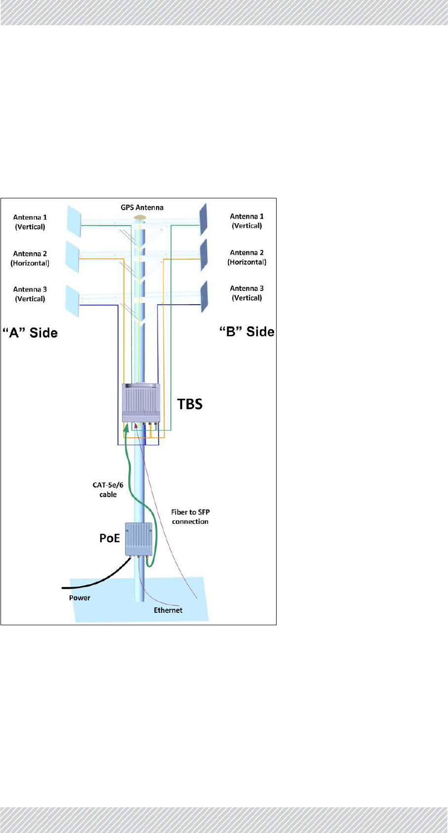
Therearethreeantennasforeachstream:Aisforapproachingtrains,andBisfor
recedingtrains(seeFigure 1‐1).Separatetheantennasasmuchaspossible,and
maintainthefollowingminimaldistances:
•Minimumverticaldistancebetweeneachantennais1.0m.
•MinimumhorizontaldistancebetweenAntenna1andAntenna2is1.6m.
For Regualtor Approval Only
FinMDeploymentGuide Release4.2.46 1‐2
TBS&Antennas‐GeneralMountingArrangement SiteInstallation
•MinimumhorizontaldistancebetweenAntenna3andAntenna2is1.0m
•Minimumtotalhorizontaldistance(betweenAntenna1andAntenna3)is2.6m
1.2.2TBS&Antennas‐GeneralMountingArrangement
TheTBScanbemountedonapoleorawall,togetherwithitsantennas,LPUsandPoEdevice.
ToenablebetterMIMOconditions,theantennasshouldbedividedbetweenverticaland
horizontalpolarizations.Figure 1‐1showsaschematicviewwiththesepolarizations.
Figure1‐1:TBS‐BaseStationmountingwithantennas
For Regualtor Approval Only
FinMDeploymentGuide Release4.2.46 1‐3
TBS‐Mounting SiteInstallation
1.2.3TBS‐Mounting
TheTBScanbemountedonaverticalorhorizontalpole,oronawall.
•Verticalpole:seepage 1‐5fordirectionsrelevanttoallsizes.
•Thinpole:seepage 1‐6.
•Mediumpole:seepage 1‐7
•Thickpole:seepage 1‐8
• Horizontalpole:seepage 1‐8fordirectionsrelevanttoallsizes.
•Thinpole:seepage 1‐10.
•Mediumpole:seepage 1‐11
•Thickpole:seepage 1‐12
• Wall:TheTBScanbemountedonawall,seepage 1‐12.
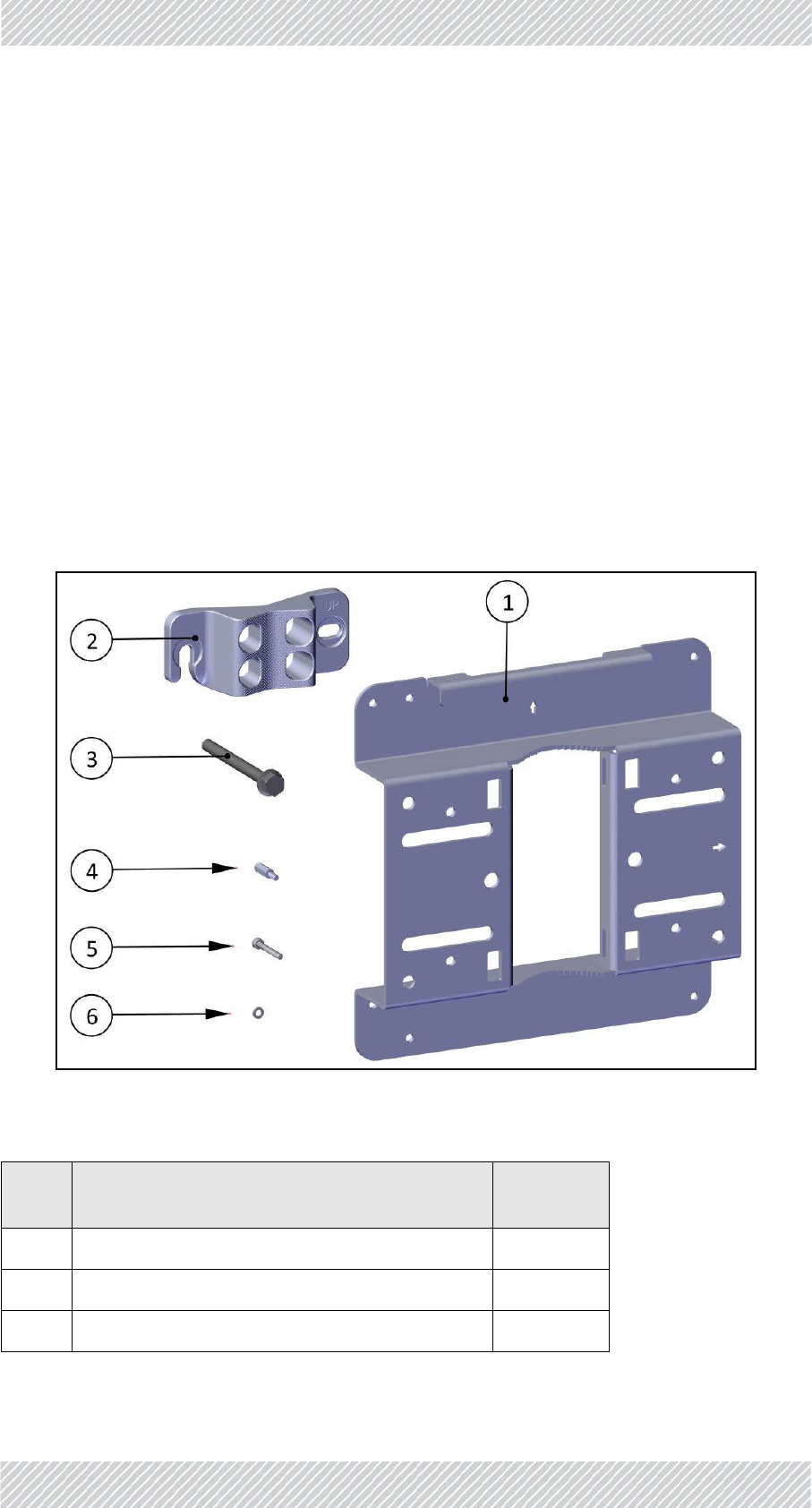
Checkthepackagecontents:
Figure1‐2:TBSmountingkitpackagecontents
Table1‐1:TBSmountingkitpackagecontents
Item
No. Description Quantity
1Baseplate 1
2Poleclamp 1
3HexscrewwithflangeM8x90 2
For Regualtor Approval Only

FinMDeploymentGuide Release4.2.46 1‐4
TBS‐Mounting SiteInstallation
4StandoffsM4x16 4
5AllenscrewsM4x30 4
6Washersforallenscrews 4
Table1‐1:TBSmountingkitpackagecontents(Continued)
Item
No. Description Quantity
For Regualtor Approval Only
FinMDeploymentGuide Release4.2.46 1‐5
TBS‐Mounting SiteInstallation
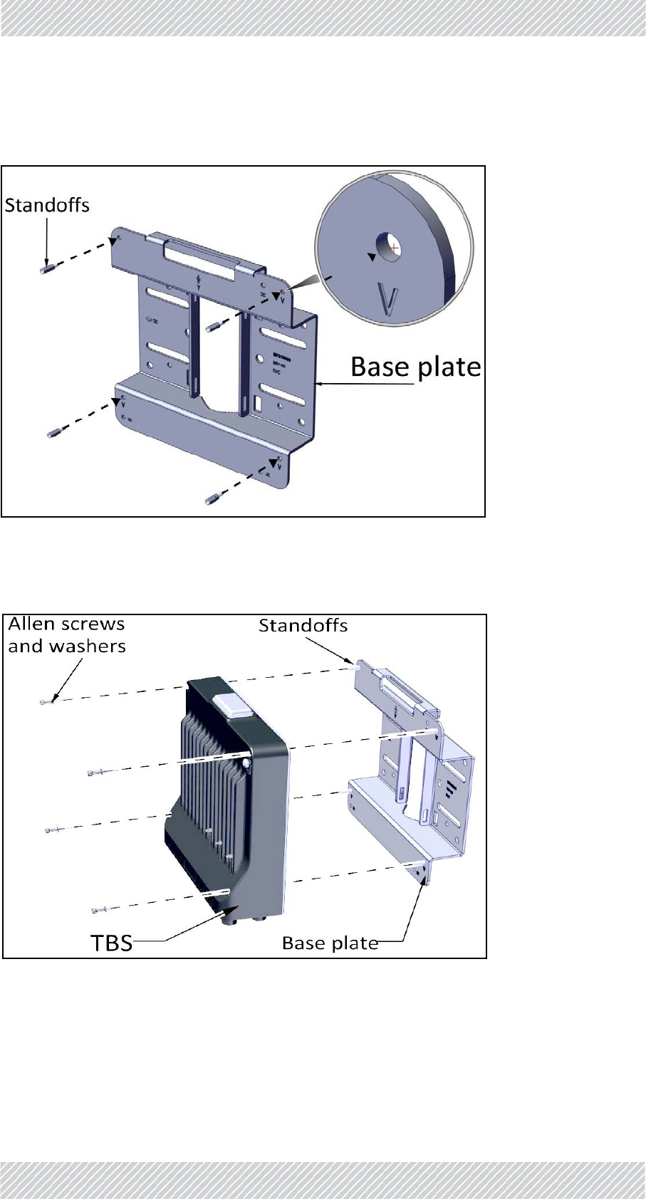
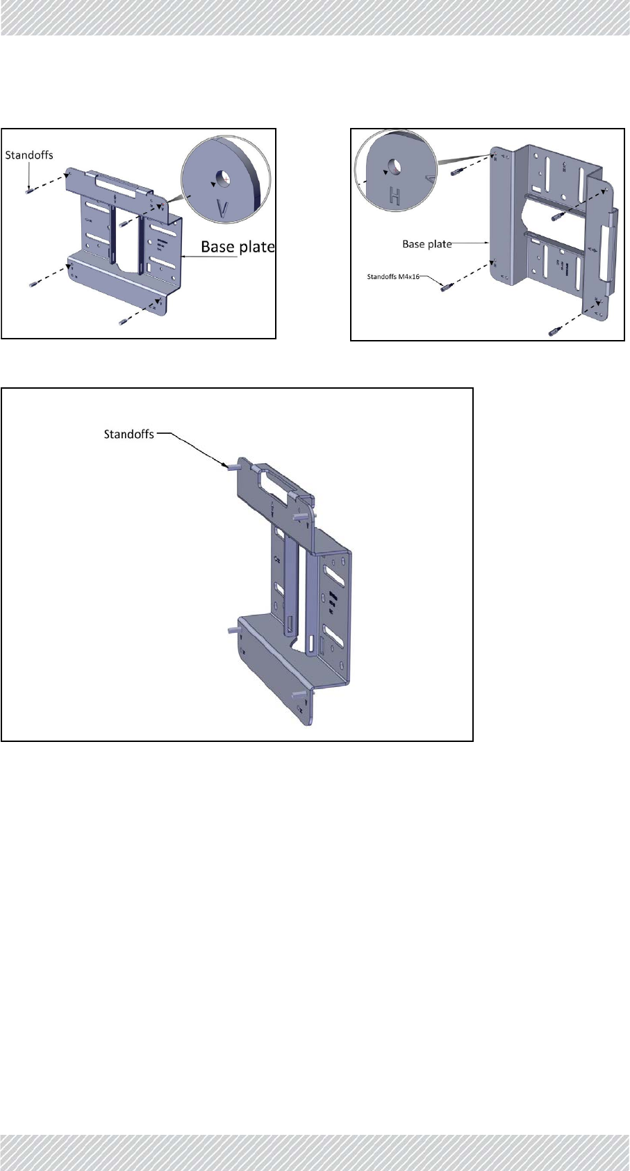
VerticalPole‐allsizes
1. Fastenthestandoffstothebaseplateintheholeslabeled“V”asshown:
Figure1‐3:Fastenstandoffstobaseplate(forverticalpole)
2. PlacetheTBSasshownoverthestandoffs,andusingtheAllenscrewsandwashers,fasten
theTBStothebaseplate.
Figure1‐4:FastenTBStobaseplate(forverticalpole)
For Regualtor Approval Only
FinMDeploymentGuide Release4.2.46 1‐6
TBS‐Mounting SiteInstallation
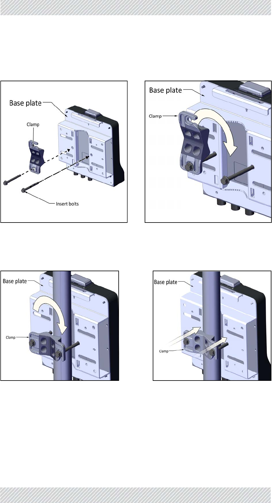
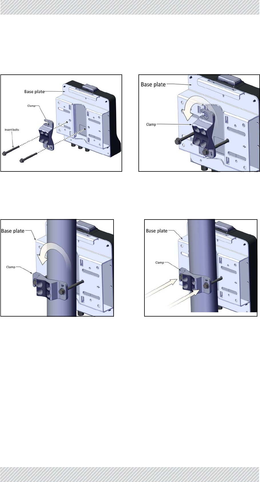
VerticalPole‐thin
1. Diameter3/4to11/2:BeforeraisingtheTBSonthepole,positionthepoleclampasshown
inthefollowingtwofigures.Donotcompletelytightenthebolts:
Thinpole(diameter3/4to11/2):Positionthepoleclampasshowninthefoll owing twofigures,donotcompletelytightenthebolts:
2. PlacethisassemblyonthepolewhereyouwanttomounttheTBS.Onceitisinplace,
rotatethepoleclampasshown,thentightenbothbolts.
Figure1‐5:Thinpole:Fastenclamptobase
plate
Figure1‐6:Thinpole:Donotcompletely
tightenbolts
Figure1‐7:Thinpole:Rotateclamp Figure1‐8:Thinpole:tightenbolts
For Regualtor Approval Only
FinMDeploymentGuide Release4.2.46 1‐7
TBS‐Mounting SiteInstallation
Verticalpole‐medium
1. Diameter2to3:BeforeraisingtheTBSonthepole,positionthepoleclampasshownin
thefollowingtwofigures.Donotcompletelytightenthebolts:
2. PlacethisassemblyonthepolewhereyouwanttomounttheTBS.Onceitisinplace,
rotatethepoleclampasshown,thentightenbothbolts.
Figure1‐9:Mediumpole:Fastenclampto
baseplate
Figure1‐10:Mediumpole:Donotcom‐
pletelytightenbolts
Figure1‐11:Mediumpole:Rotateclamp Figure1‐12:Mediumpole:tightenbolts
For Regualtor Approval Only
FinMDeploymentGuide Release4.2.46 1‐8
TBS‐Mounting SiteInstallation
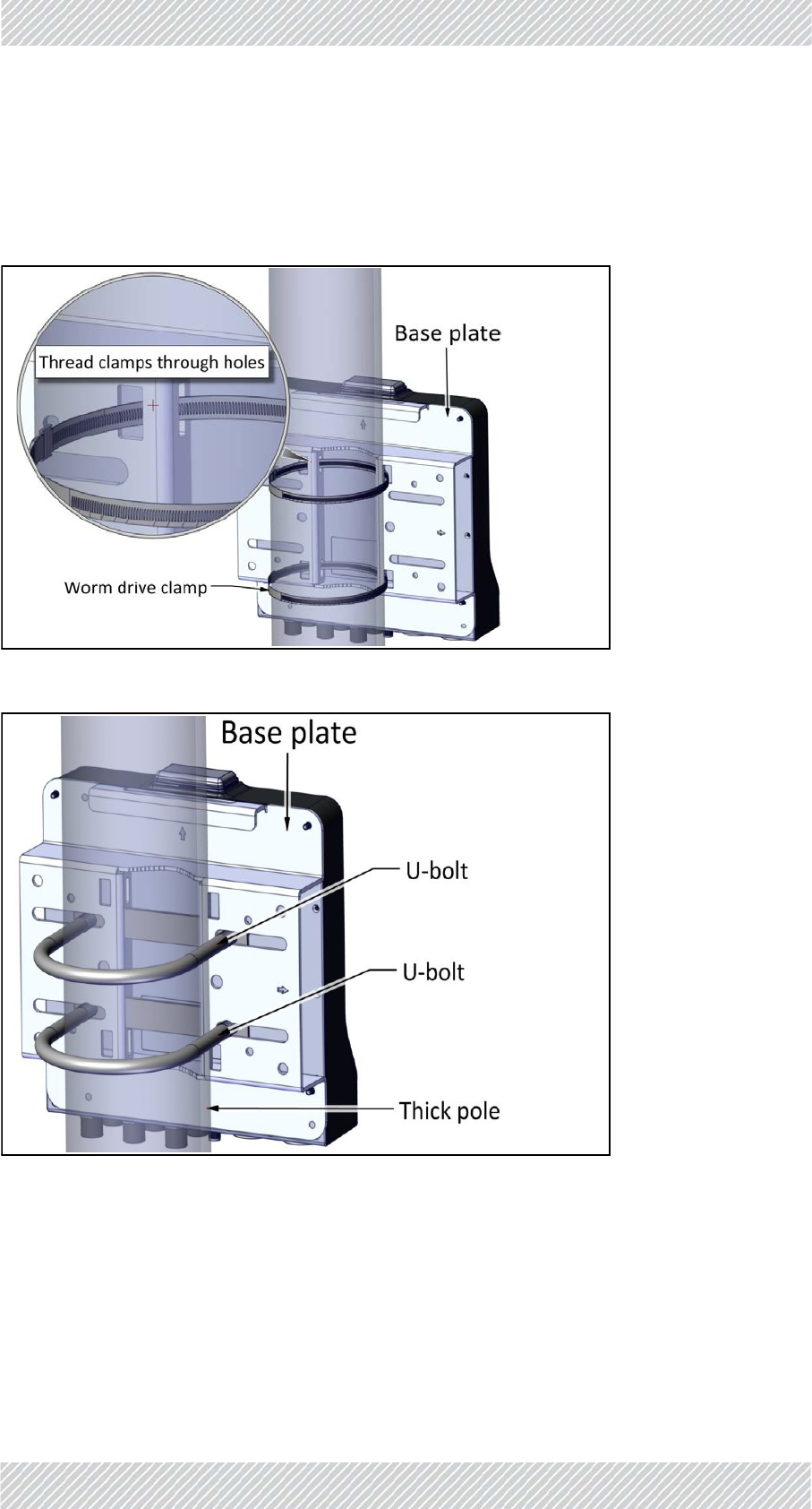
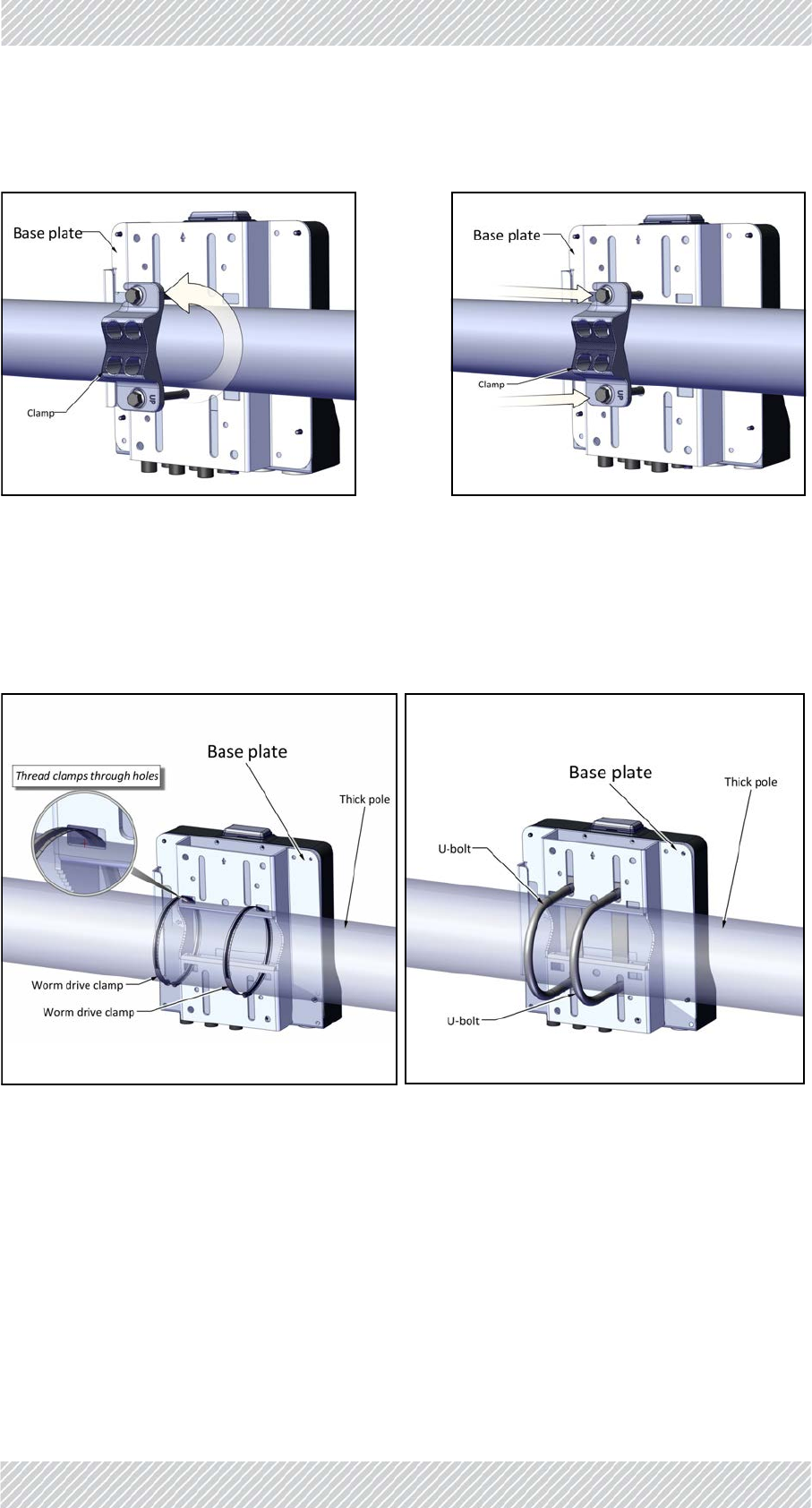
VerticalPole‐thick
1. Diameterlargerthan3:Usewormdriveclamps(notsupplied),threadedthroughtheholes
asshowninFigure 1‐13,orU‐bolts(notsupplied),fastenedusingtheholesasshownin
Figure 1‐14:
Figure1‐13:Usingwormdriveclampsforathickpole
Figure1‐14:UsingU‐boltsforathickpole
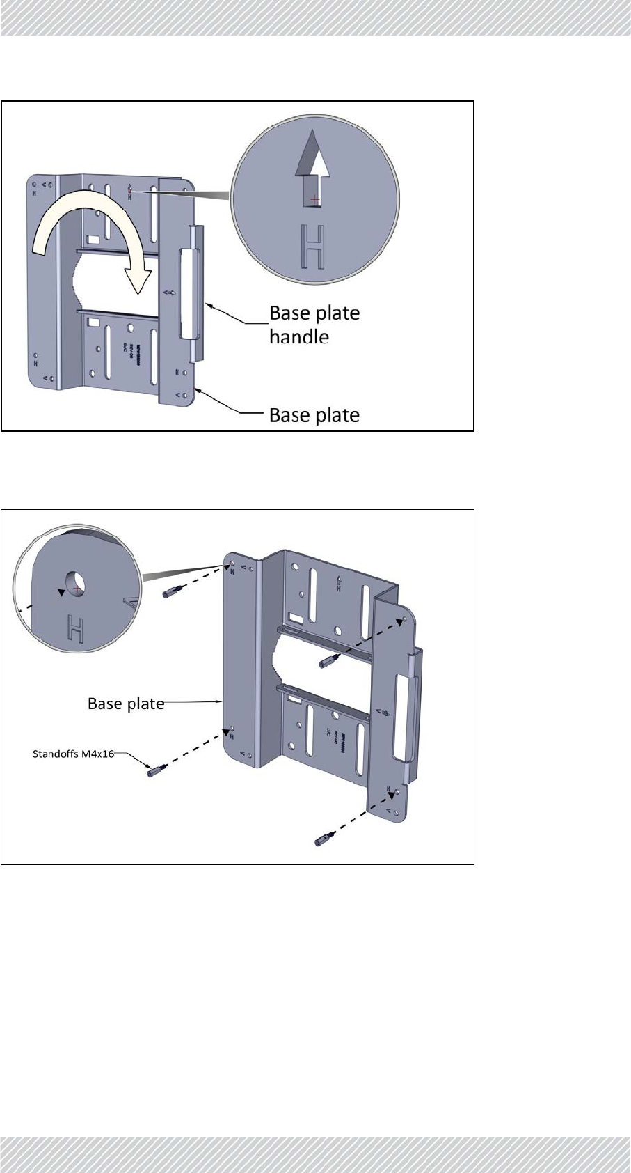
HorizontalPole‐allsizes
1. BeforefasteningtheTBStothebaseplate(seeStep1.onpage 1‐5),rotatetheplateby90o
clockwise.Makesurethearrownexttothe“H”pointsup.
For Regualtor Approval Only
FinMDeploymentGuide Release4.2.46 1‐9
TBS‐Mounting SiteInstallation
Figure1‐15:Rotatebaseplateclockwise90oforhorizontalpole
2. Fastenthestandoffstothebaseplateintheholeslabeled“H”asshown:
Figure1‐16:Fastenstandoffstobaseplate(forhorizontalpole)
3. PlacetheTBSasshownoverthestandoffs,andusingtheAllenscrewsandwashers,fasten
theTBStothebaseplate.
For Regualtor Approval Only

FinMDeploymentGuide Release4.2.46 1‐10
TBS‐Mounting SiteInstallation
Figure1‐17:FastenTBStobaseplate(forhorizontalpole)
HoriztonalPole‐thin
1. Diameter3/4to11/2:BeforeraisingtheTBSonthepole,positionthepoleclampasshown
inthefollowingtwofigures.Donotcompletelytightenthebolts:
Thinpole(diameter3/4to11/2):Positionthepoleclampasshowninthefoll owing twofigures,donotcompletelytightenthebolts:
Figure1‐18:Thinpole:Fastenclamptobase
plate
Figure1‐19:Thinpole:Donotcompletely
tightenbolts
For Regualtor Approval Only
FinMDeploymentGuide Release4.2.46 1‐11
TBS‐Mounting SiteInstallation
2. PlacethisassemblyonthepolewhereyouwanttomounttheTBS.Onceitisinplace,
rotatethepoleclampasshown,thentightenbothbolts.
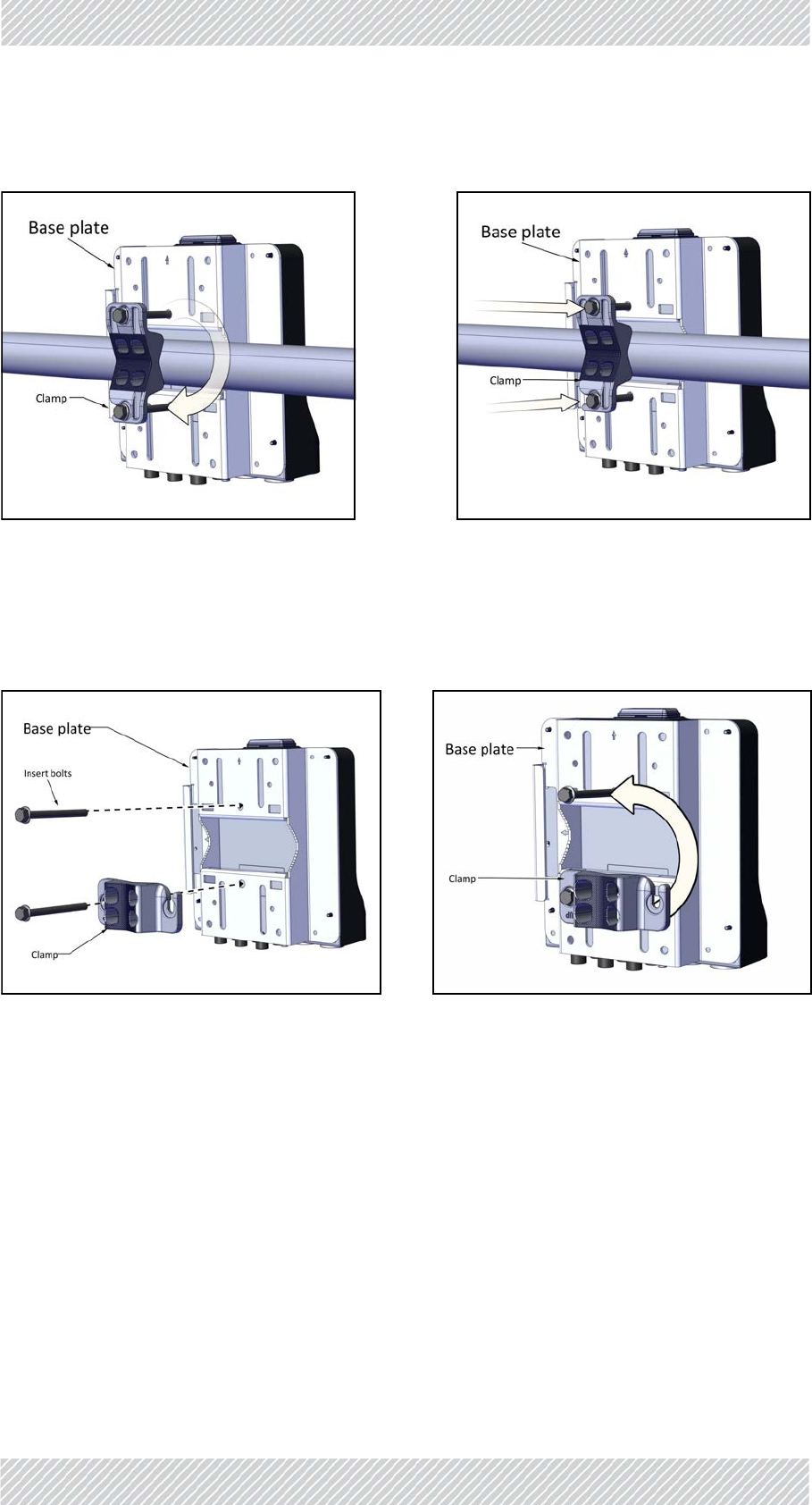
HorizontalPole‐medium
1. Diameter2to3:BeforeraisingtheTBSonthepole,positionthepoleclampasshownin
thefollowingtwofigures.Donotcompletelytightenthebolts:
Figure1‐20:Thinpole:Rotateclamp Figure1‐21:Thinpole:tightenbolts
Figure1‐22:Mediumpole:Fastenclampto
baseplate
Figure1‐23:Mediumpole:Donotcom‐
pletelytightenbolts
For Regualtor Approval Only
FinMDeploymentGuide Release4.2.46 1‐12
TBS‐Mounting SiteInstallation
2. PlacethisassemblyonthepolewhereyouwanttomounttheTBS.Onceitisinplace,
rotatethepoleclampasshown,thentightenbothbolts.
HoriztonalPole‐thick
1. Diameterlargerthan3:Usemetalbands(notsupplied),threadedthroughtheholesas
showninFigure 1‐26,orU‐bolts(notsupplied),fastenedusingtheholesasshownin
Figure 1‐27:
Mountingonawall
1. Fastenthestandoffstothebaseplateintheholeslabeled“V”or“H”,whicheverismore
convenient,asshown:
Figure1‐24:Mediumpole:Rotateclamp Figure1‐25:Mediumpole:tightenbolts
Figure1‐26:UsingmetalbandsforalargepoleFigure1‐27:UsingU‐boltsforalargepole
For Regualtor Approval Only
FinMDeploymentGuide Release4.2.46 1‐13
TBS‐Mounting SiteInstallation
Figure1‐29:Standoffsfastenedtobaseplate
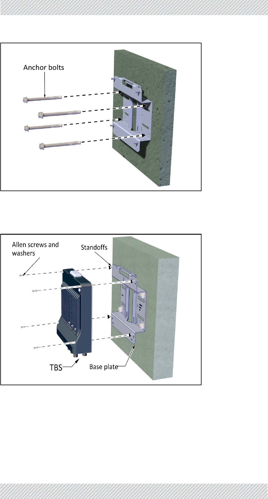
2. Useanchorboltstoattachbaseplatetoawall,asshown:
OR
<‐>
Figure1‐28:Fastenstandoffstobaseplate
For Regualtor Approval Only
FinMDeploymentGuide Release4.2.46 1‐14
TBS‐Mounting SiteInstallation
Attachthebaseplatetoawallusing9mmdia.anchorbolts(notsupplied)intheholesindicated.
Figure1‐30:Attachbaseplatetowall
3. PlacetheTBSasshownoverthestandoffs,andusingtheAllenscrewsandwashers,fasten
theTBStothebaseplate.
Figure1‐31:FastenTBStobaseplateonwall
For Regualtor Approval Only
FinMDeploymentGuide Release4.2.46 1‐15
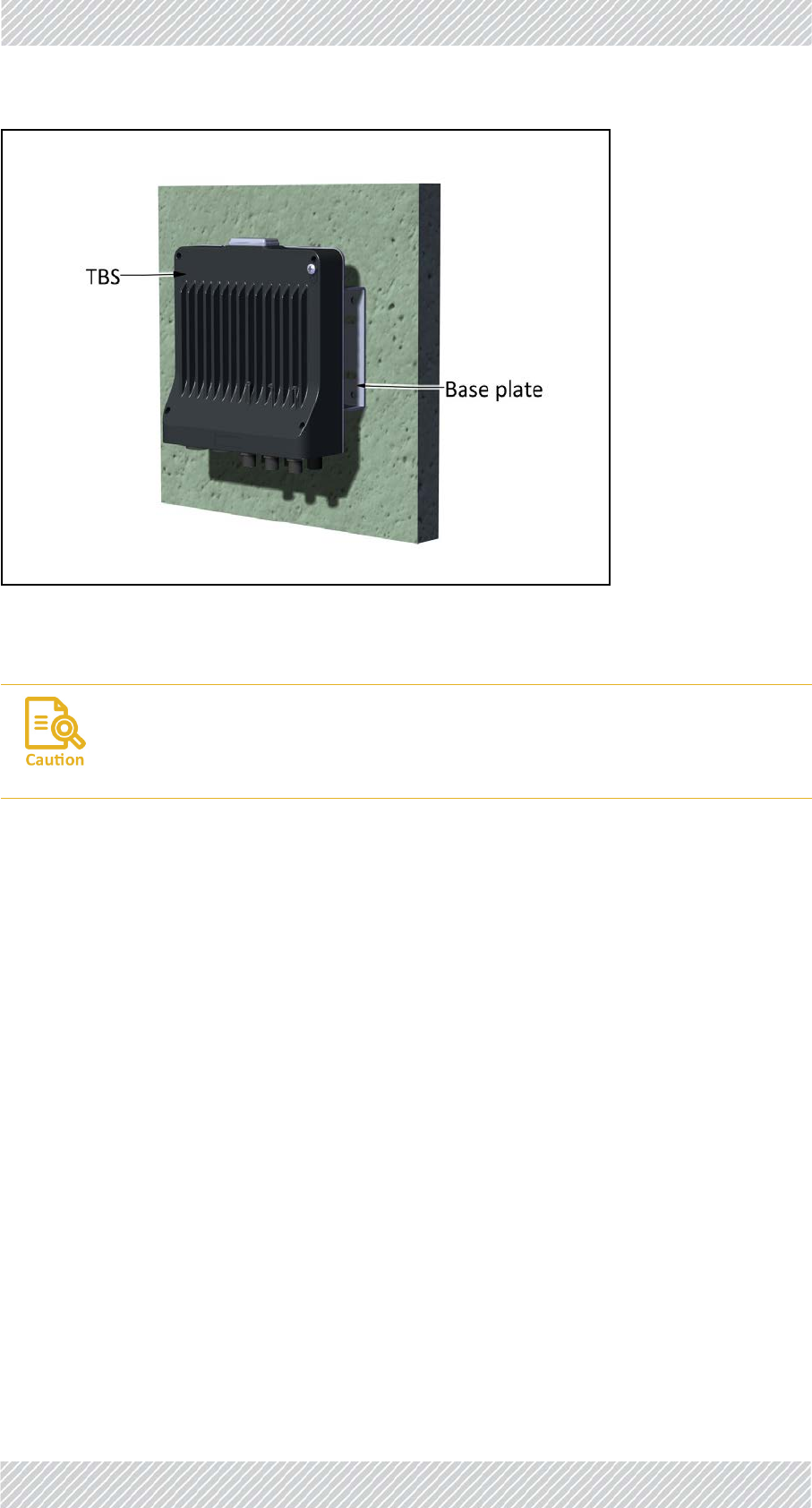
PoEDevicesfortheTBS SiteInstallation
Figure1‐32:TBSmountedonawall
1.2.4PoEDevicesfortheTBS
TheTBSissuppliedbyanACPoEdevice,eitherviaanoutdoorunitmountedinthesame
mannerasanantenna,orviaanindoorunit,installedinanelectricalhut.
(TheTMUhasitsownPoE,seePoEDevicefortheTMUonpage 1‐42).
1.2.5TBSAntennas
TBSAntennaMountingKit
Usetheantennamountingkit(differentfromtheTBSmountingkit)tomountaTBSantenna
onapoleorwall.ThesamemountingkitisusedtomountanexternalACPoEdevice.
AlwaysmountaTBSwiththeconnectorsonthebottom.Nevermounta
unithorizontally.
For Regualtor Approval Only
FinMDeploymentGuide Release4.2.46 1‐16
TBSAntennas SiteInstallation
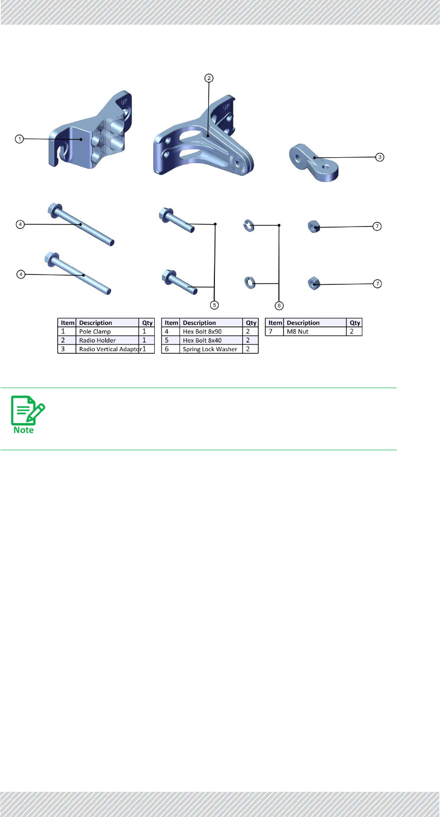
Figure1‐33:AntennaMountingKitContents
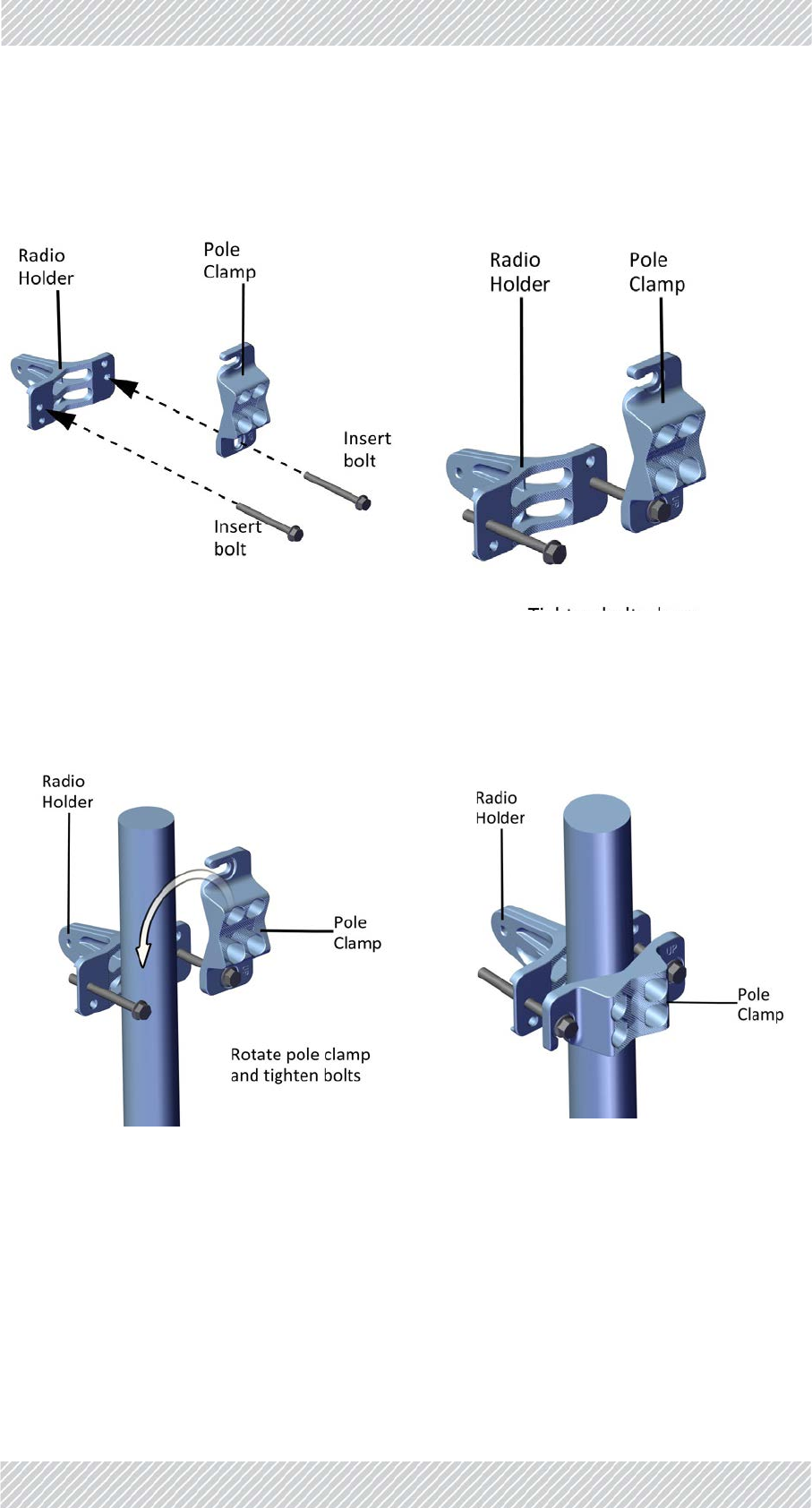
TBSAntennaMountingonaMediumPole
ThismethodisformountingtheTBSantennaonapoleofpipesize2to3.
4. Connectthepoleclamptotheradioholderwiththe8x90bolts,butdonottighten
theboltsalltheway‐tightenthemsothattheyarenotcloserthanadistance
equaltotheradiusofthepole.Youwillthenhaveone“unit”thatyoucantaketo
Tightenallboltswithatorqueof15Nm.
For Regualtor Approval Only
FinMDeploymentGuide Release4.2.46 1‐17
TBSAntennas SiteInstallation
thelocationonthepolewhereyouwanttomounttheantenna.(SeeFigure 1‐38
toFigure 1‐41formountingonathinpole)
5. Placethis“unit”onthepolewhereyouwanttomounttheantenna.Onceitisin
place,rotatethepoleclampasshown,thentightenbothbolts.
TBSAntennaMountingonaThickPole
ThismethodisformountingtheTBSantennaonapoleofpipesizelargerthan3.
Figure1‐34:ConnectPoleClamptoRadio
Holder
Figure1‐35:Tightenbolts
Figure1‐36:RotateClampandtightenbolts Figure1‐37:MountingKitonpole
For Regualtor Approval Only
FinMDeploymentGuide Release4.2.46 1‐18
TBSAntennas SiteInstallation
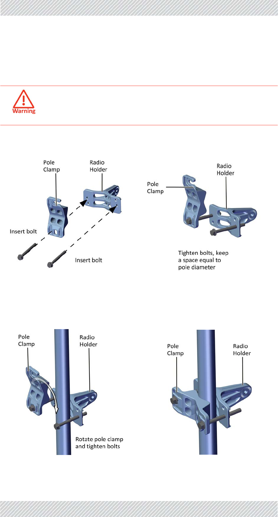
TBSAntennaMountingonaThinPole
ThismethodisformountingtheTBSantennaonapoleofpipesize3/4to11/2.
1. Whenmountingonathinpole,positionthepoleclampasshowninthefollowingfigures:
2. Placethis“unit”onthepolewhereyouwanttomounttheantenna.Onceitisin
place,rotatethepoleclampasshown,thentightenbothbolts.
DonotmounttheTBSantennaonapolesmallerthan3/4.
Figure1‐38:ConnectPoleClamptoRadio
Holder
Figure1‐39:Tightenbolts
Figure1‐40:RotateClampandtightenbolts Figure1‐41:MountingKitonthinpole
For Regualtor Approval Only
FinMDeploymentGuide Release4.2.46 1‐19
TBSAntennas SiteInstallation
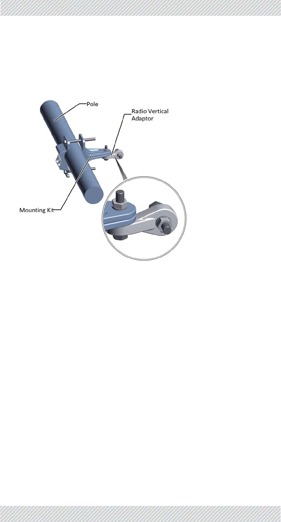
TBSAntennaMountingonaHorizontalPole
Whenusingthemountingkitonahorizontalpole,usetheradioverticaladaptor,asshown:
Figure1‐42:Mountingkitonahorizontalpole
For Regualtor Approval Only
FinMDeploymentGuide Release4.2.46 1‐20
TBSAntennas SiteInstallation
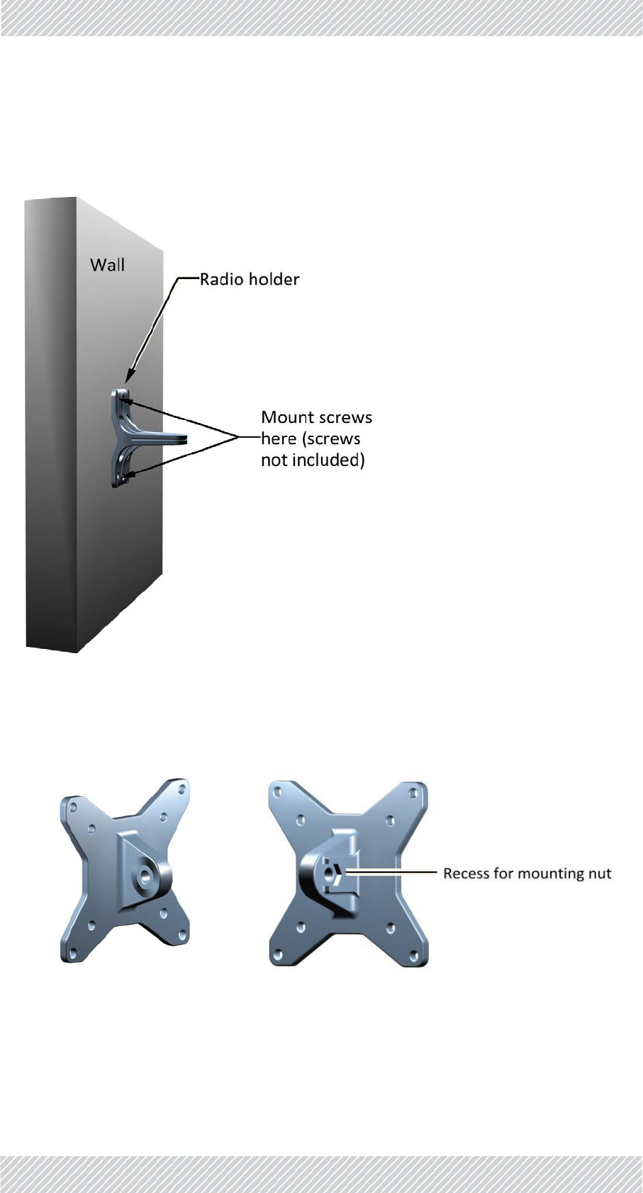
TBSAntennaMountingonaWall
Whenusingthemountingkitonawall,thepoleclampisnotnecessary:
TBSAntennaMountingKitAdaptor
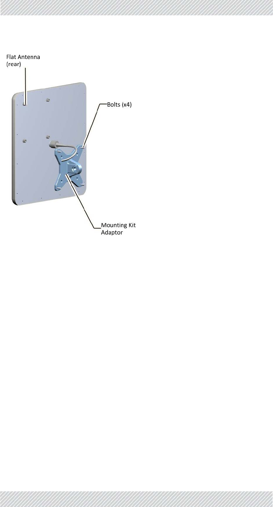
AflatpanelantennasuchasthatshowninFigure 1‐44istypicallyused.Ithasfourboltsfora
mountingkitadapter.ThemountingkitadaptorappearsasshowninFigure 1‐43:
Figure1‐43:Flatpanelantennamountingkitadapter
Attachthemountingkitadaptortotherearoftheantennaasshown:
For Regualtor Approval Only
FinMDeploymentGuide Release4.2.46 1‐22
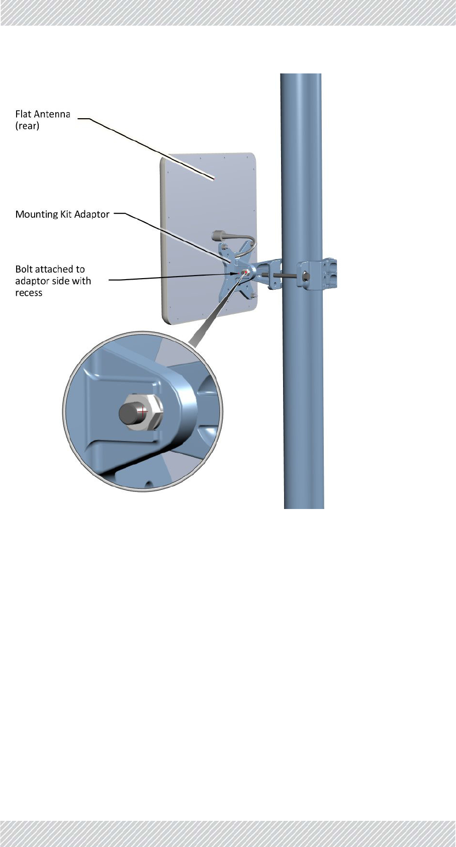
TBSAntennas SiteInstallation
Figure1‐45:FlatPanelantenna‐mountedonapole
For Regualtor Approval Only
FinMDeploymentGuide Release4.2.46 1‐23
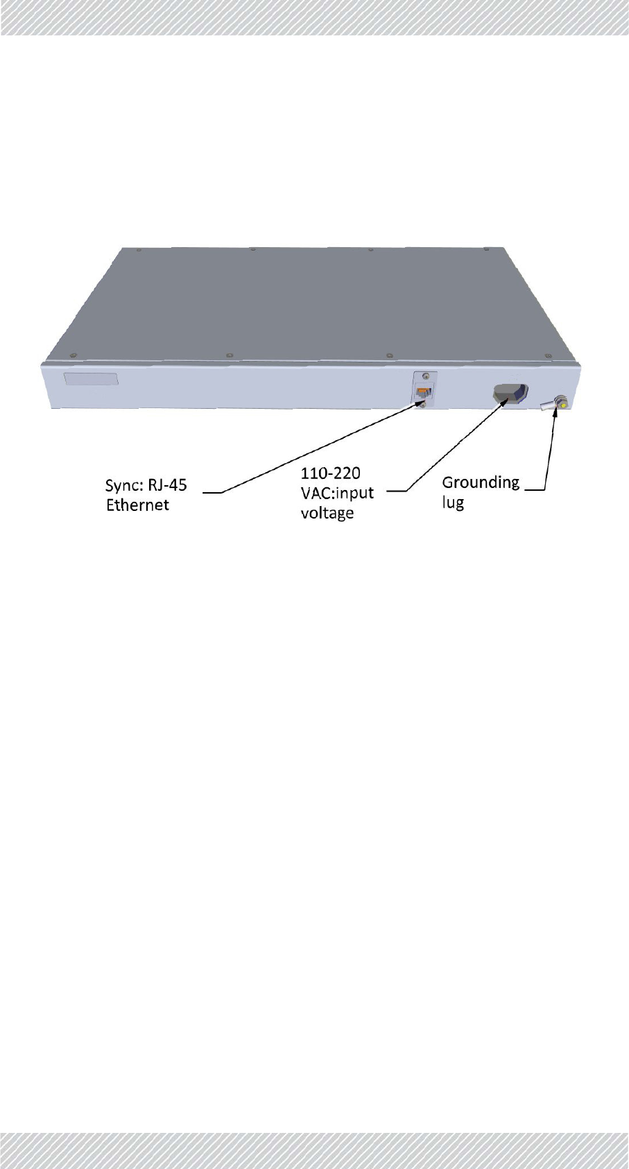
IndoorSynchronizationUnit(ISU) SiteInstallation
1.2.6IndoorSynchronizationUnit(ISU)
TheIndoorSynchronizationUnit(ISU)providesamastersynchronizationclockforallTBS
units,andisconnectedtooneofthenetworkswitches.
Itcanbeinstalledona19in.rackoronaconvenientsurfaceinthenetworkoperatingcenter.
Figure1‐46:IndoorSynchronizationUnit(ISU)
For Regualtor Approval Only
FinMDeploymentGuide Release4.2.46 1‐24
LightningProtectionUnit SiteInstallation
1.2.7LightningProtectionUnit
Theuseoflightningprotectionisdependentonregulatoryandenduserrequirements.
AlthoughFinMunitshavesurgelimitingcircuitsthatminimizetheriskofdamagedueto
lightningstrikes,RADWINrecommendstheuseofadditionalsurgearrestordevicestoprotect
theequipmentfromnearbylightningstrikes.
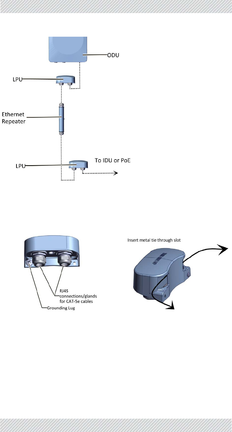
Foranytypeofindoorunit‐outdoorunitconnection,lightningprotectionunits(LPUs)are
installedinpairs,asshowninFigure 1‐47:
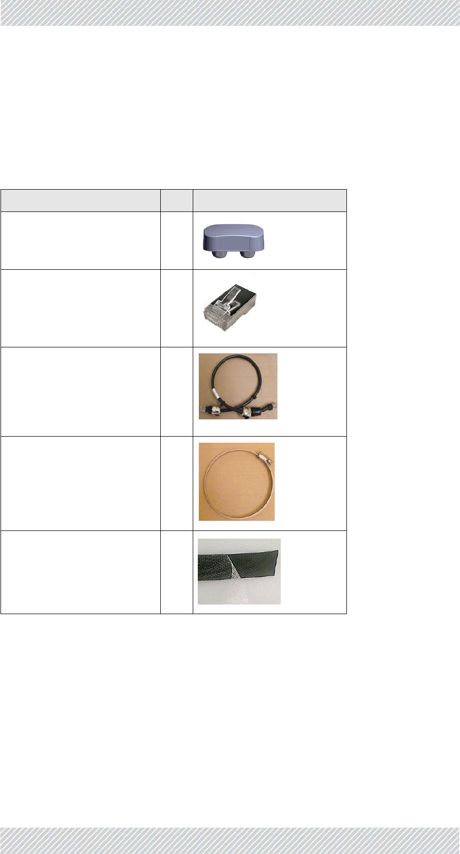
Table1‐2:LPUKitcontents
Item Qty View/Remarks
LPU 1
RJ‐45connectors2
0.5mCAT‐5ecable1
Metaltie 1
ScotchTM23Tape2
For Regualtor Approval Only
FinMDeploymentGuide Release4.2.46 1‐25
LightningProtectionUnit SiteInstallation
Figure1‐47:Basicuseoflightningprotectorunits
TheLPUhastwocableglandsonthebottomforCAT‐5e/6cables,inadditiontoagrounding
lug.Thereisanextraholeforasecondscrewwheninstalledonawall.OnthesideoftheLPU
isaslotforthemetaltiewheninstalledonapole,asshowninFigure 1‐48andFigure 1‐49:
ToinstallanLPUonapole:
1.Choosealocationascloseaspossibletotheradiounit.
2. InsertthemetaltiethroughtheslotsasshowninFigure 1‐49.MakesuretheLPUis
orientedinthecorrectdirection,asshowninFigure 1‐50.
Figure1‐48:LPU:BottomView Figure1‐49:LPU:SideView
For Regualtor Approval Only
FinMDeploymentGuide Release4.2.46 1‐26
LightningProtectionUnit SiteInstallation
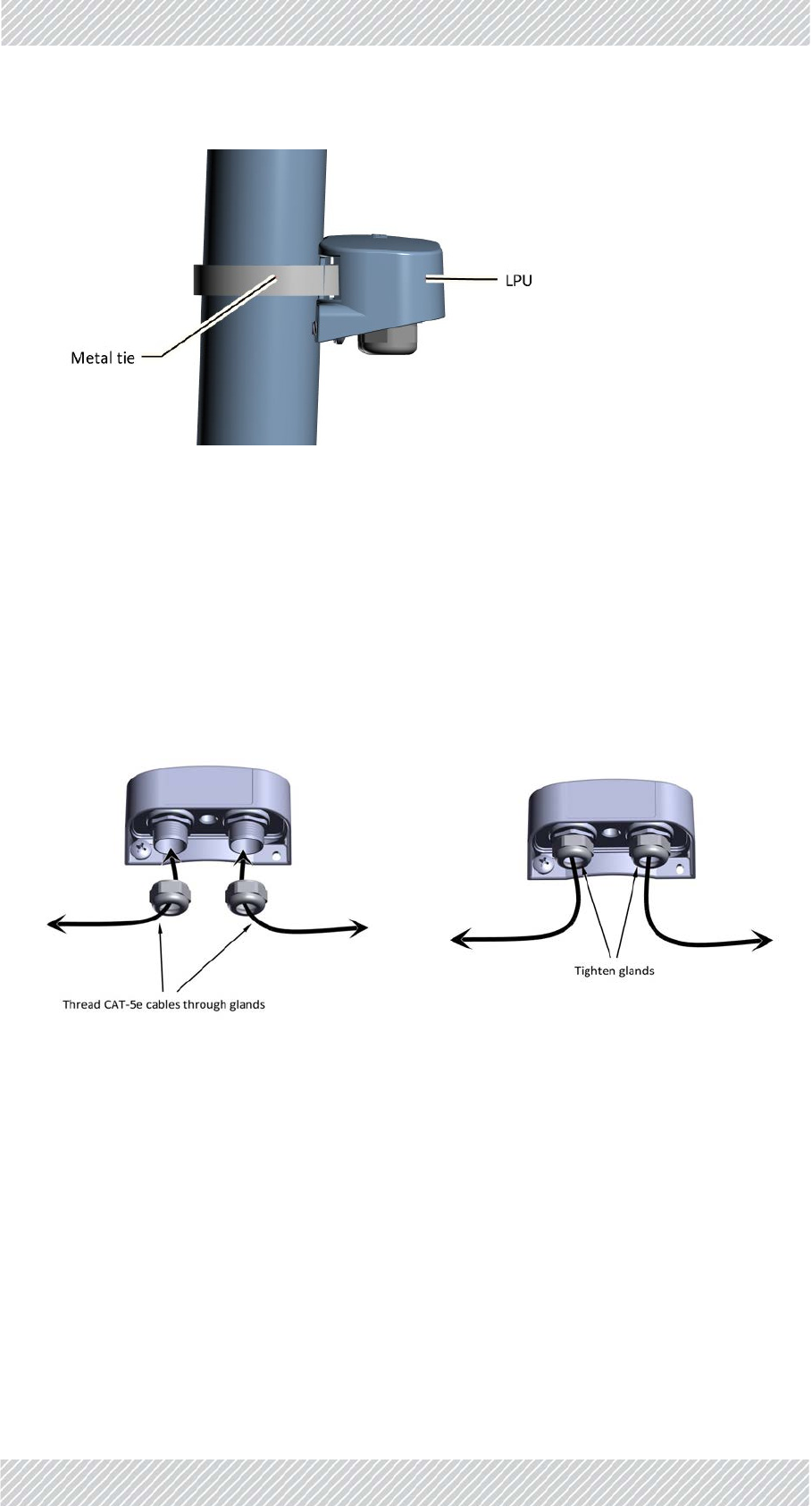
Figure1‐50:LPUattachedtopolewithmetaltie
3. Tightenthemetaltie.
4. Connectthegroundinglugtoagroundingsource.
5. Removethecableglands.
6. ThreadtheCAT‐5e/6cablesthroughthecableglands,andconnectthecablestothe
LPUasshowninFigure 1‐51.
7. TightenthecableglandsaroundtheCAT‐5ecablesasshowninFigure 1‐52.
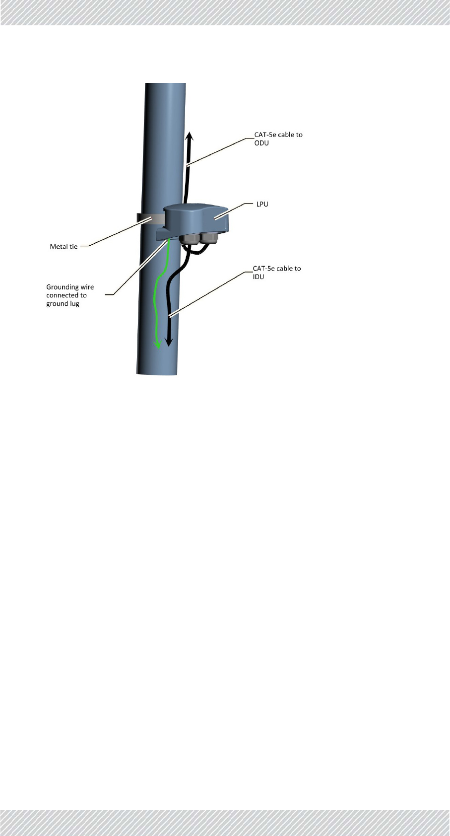
8. RouteoneCAT‐5e/6uptotheradio,andtheotherdowntotheIDUorPoE(viathe
lowerLPU).AnLPUinstalledonapoleisshowninFigure 1‐53.
9. RADWINrecommendsthatyouaddextrawaterproofingtotheconnections
(seesee"Waterproofing"onpage1‐28.).
Figure1‐51:ConnectingcablestotheLPU(1) Figure1‐52:ConnectingcablestotheLPU(2)
For Regualtor Approval Only
FinMDeploymentGuide Release4.2.46 1‐27
LightningProtectionUnit SiteInstallation
Figure1‐53:InstallinganLPUonapole(sideview)
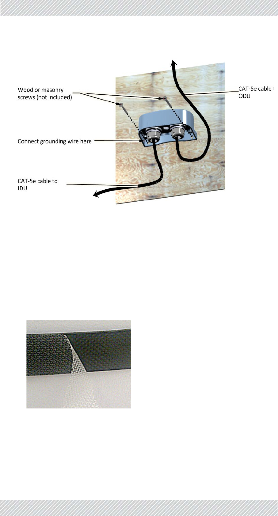
ToinstallanLPUonawall:
1.Removethegroundinglug.
2. AttachtheLPUtothewallusingwoodormasonryscrews(notincluded),viathe
holesasshowninFigure 1‐54.
3. Connecttheleftscrew(wherethegroundinglugwaslocated)toagroundsource.
4. Removethecableglands.
5. ThreadtheCAT‐5e/6cablesthroughthecableglands,andconnectthecablestothe
LPUasshowninFigure 1‐51.
6. TightenthecableglandsaroundtheCAT‐5e/6cablesasshowninFigure 1‐52.
7. RouteoneCAT‐5euptotheradio(viatheupperLPU),andtheothertotheIDUor
PoE.
8. RADWINrecommendsthatyouaddextrawaterproofingtotheconnections
(seeseeWaterproofingonpage 1‐28).
For Regualtor Approval Only
FinMDeploymentGuide Release4.2.46 1‐28
Waterproofing SiteInstallation
Figure1‐54:InstallinganLPUonawall
1.2.8Waterproofing
Protectallconnectionsbetweenanyoutdoordevicesandcablesfromrain,dust,moisture
andsaltaccordingtotheprocedurebelow:
1.UseahighqualitysealingmaterialsuchasScotch23Tape¾”wide,toensureIP‐67
compliantprotectionagainstwateranddust.
2. Cuttwopieceseach25cmlong,ofScotch23splicingtape.Removetheplastic
covertoexposethetackysideofthesealingtapeasshowninFigure 1‐55.
Figure1‐55:Exposingthetackysideofthesealingtape
3. Afterconnectingacabletoaunit,tightenthecableglandcapfirmlyandusethe
insulationtapetofullycoverthecablegland.
For Regualtor Approval Only

FinMDeploymentGuide Release4.2.46 1‐29
Grounding SiteInstallation
Figure1‐56:Waterproofinganexternalconnection
1.2.9Grounding
AllRADWINproductsshouldbegroundedduringoperation.Inaddition:
•Allunitsshouldbegroundedbyawirewithdiameterofatleast10AWG.
UnitsmustbeproperlygroundedtoaProtectiveGroundinaccordancewiththeLocal
ElectricalRegulations
•Rack‐mountedequipmentshouldbemountedonlyingroundedracksandcabinets.
Further,youshould‐
•Alwaysmakethegroundconnectionfirstanddisconnectitlast
•Neverconnecttelecommunicationcablestoungroundedequipment
•Ensurethatallothercablesaredisconnectedbeforedisconnectingtheground
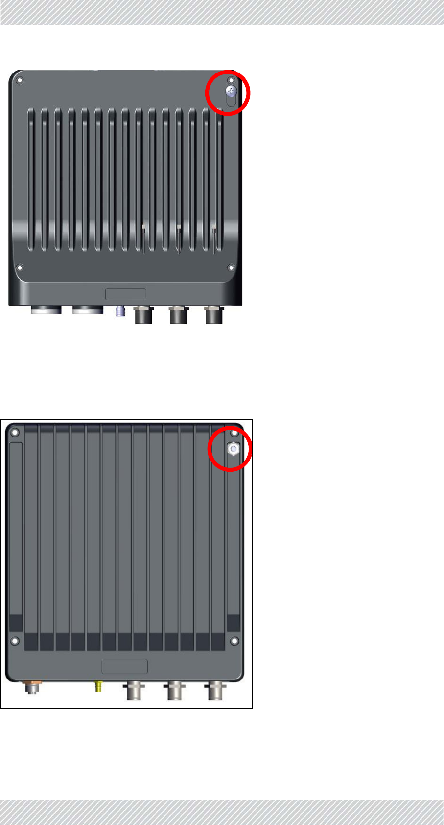
TBS
ThereisagroundinglugontheTBSasshowninFigure 1‐57.Grounditusing10AWGwire.
For Regualtor Approval Only
FinMDeploymentGuide Release4.2.46 1‐30
Grounding SiteInstallation
Figure1‐57:TBS:Groundingluglocation
TMU
ThegroundinglugfortheTMUisshowninFigure 1‐58.Grounditusing10AWGwire.
Figure1‐58:TMU:Groundingluglocation
Whenmountedina19inrack,theTMUisgroundedviatherack.
For Regualtor Approval Only
FinMDeploymentGuide Release4.2.46 1‐31
Grounding SiteInstallation
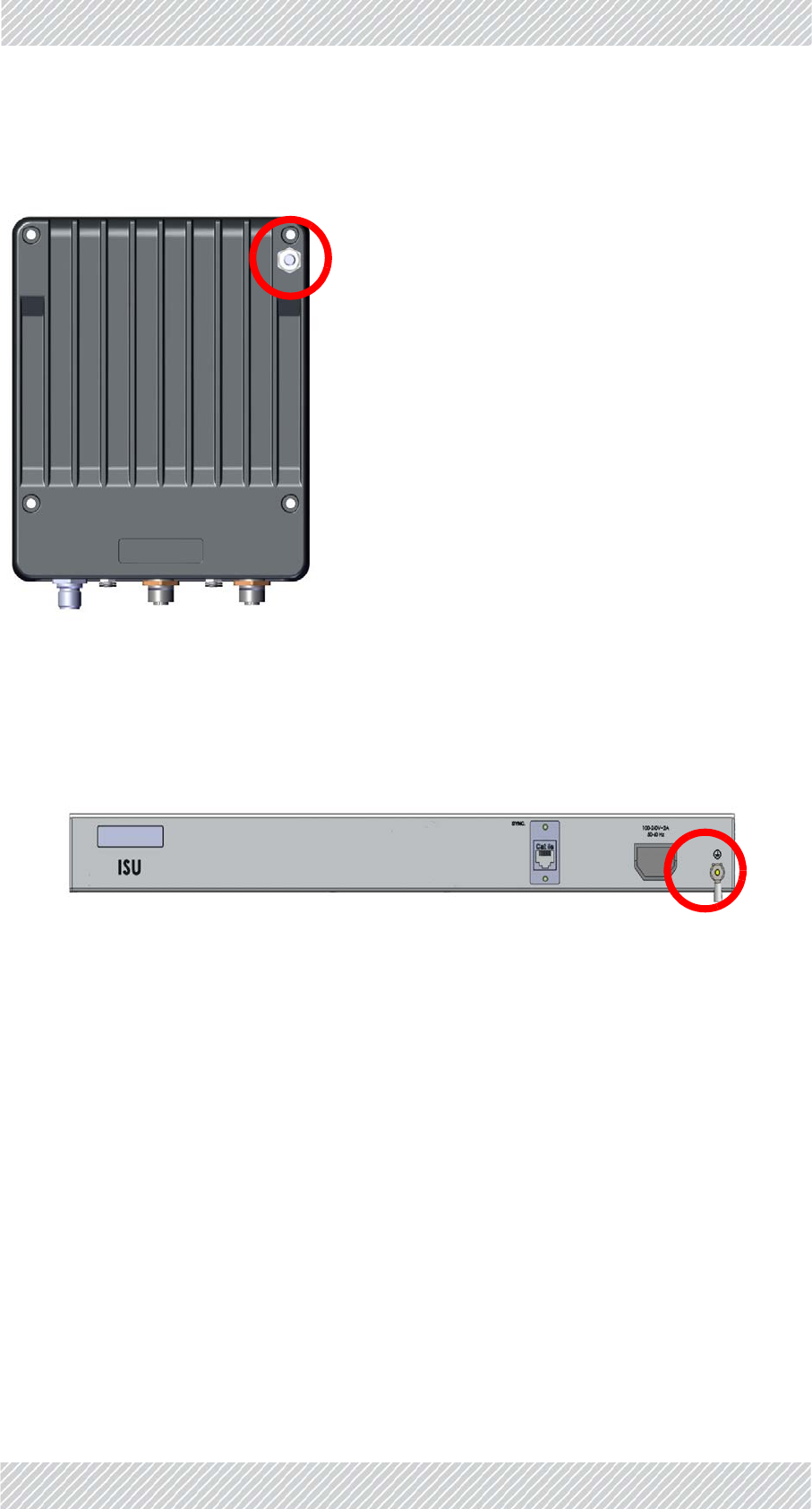
PoEDevice
ThereisagroundinglugonthePoEasshowninFigure 1‐59.Grounditusing10AWGwire.
Figure1‐59:PoE:Groundingluglocation
Whenmountedina19inrack,thePoEisgroundedviatherack.
ISU
TheISUisgroundedviaitsgroundconnectiononitsfrontpanel.
Figure1‐60:ISU:Groundingluglocation
Antennas
GroundexternalantennasusingasuitableGroundingKitsuchasanAndrewType223158‐2
(http://www.commscope.com).
For Regualtor Approval Only

FinMDeploymentGuide Release4.2.46 1‐32
TrainSide SiteInstallation
1.3TrainSide
1.3.1TMU
TMU‐Mounting
TheTMUcanbemountedina19inrack,oronawall.Whenmountingona19inrack,use
thespecially‐designedTMU‐PoEdrawer.
MountingwiththeTMU‐PoEdrawer
TheTMU‐PoEdrawerisusedtomountboththeTMUandthePoEtogether.Carryoutthe
followingstepstomountbothunits:
1. ChooseasitefortheTMU‐PoEdrawerascloseaspossibletotheon‐boardantennasand
on‐boardpowersupply.Makesurethereisatleast12cm/5inofrackspace.
2. Openthepackage,removetheTMU‐PoEdrawerfromthepackingstyrofoam,and
cutanddiscardthetwoblackstrapsholdingthemountingslidesinplace.
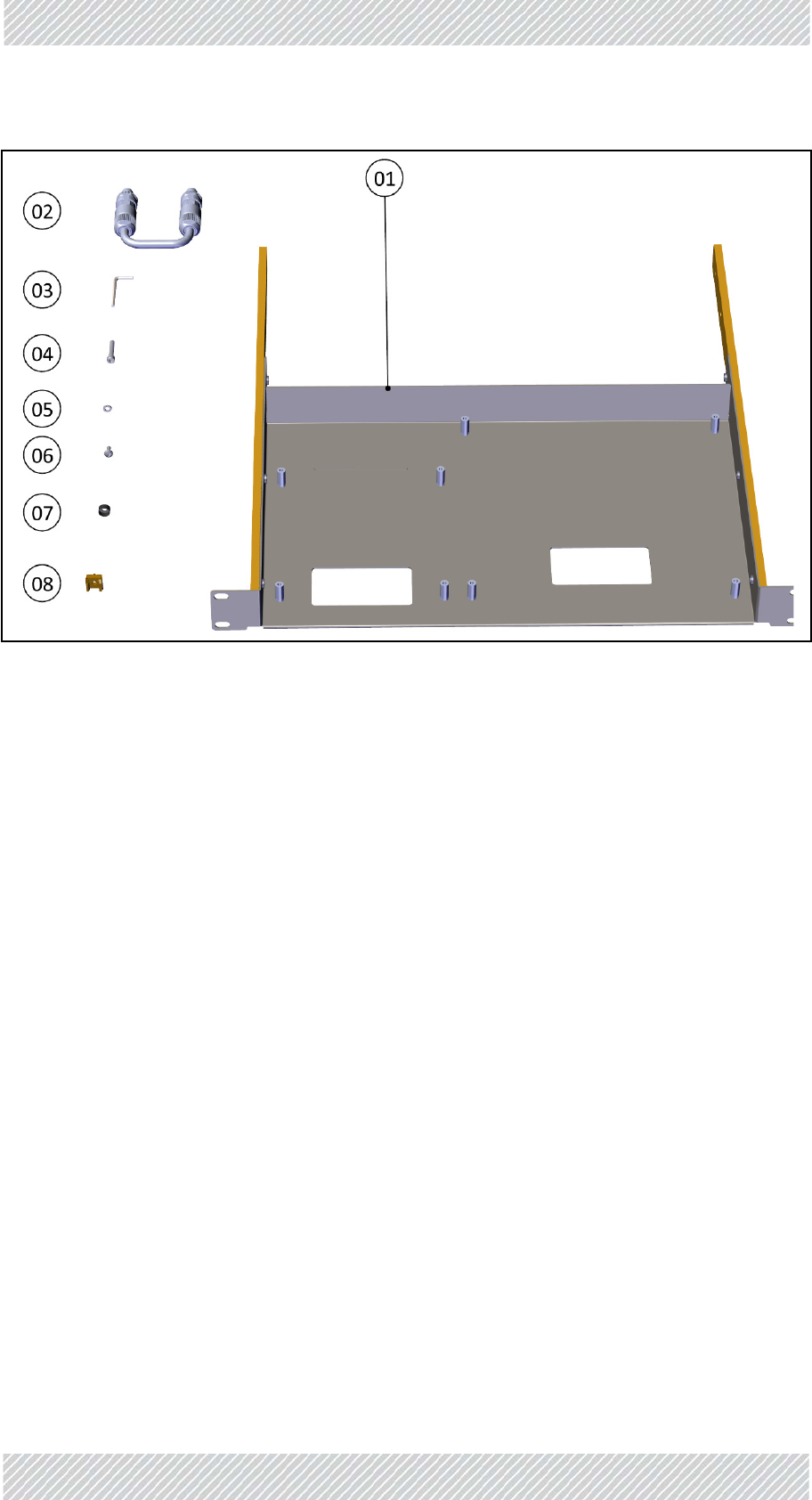
3. Checkthecontents:
Table1‐3:TMU‐PoEdrawerpackagecontents
Item
No. Description Quantity
1Tray 1
2DC‐TMUJumpercable 1
3Allenwrench(M4) 1
4Allenscrews(M4x22) 8
5SpringwashersforAllenscrews 8
6DINscrews(M5x16) 12
7BlackfinishingwashersforM5screws12
8Mechanicalcage/nutsforM5screws 12
For Regualtor Approval Only
FinMDeploymentGuide Release4.2.46 1‐33
TMU SiteInstallation
Figure1‐61:TMU‐PoEdrawercontents
For Regualtor Approval Only
FinMDeploymentGuide Release4.2.46 1‐34
TMU SiteInstallation
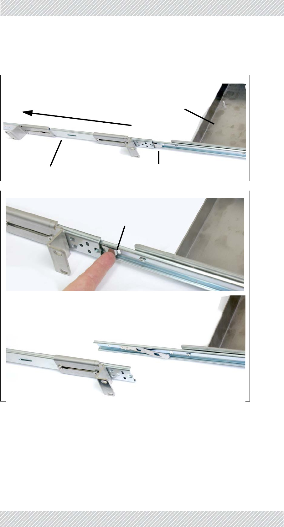
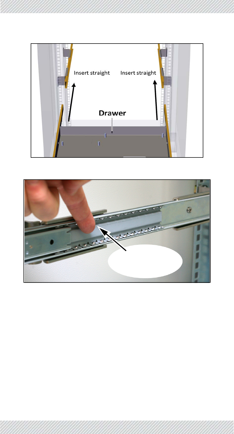
4. DetachthemountingslidesfromtheTMU‐PoEdrawer:Pulleachslideoutuntilit
isstoppedbythelockinglever.Pressthelockinglevertoreleasetheslide,andpull
slideoutcompletely.
Figure1‐62:RemovethemountingslidesfromtheTMU‐PoEdrawer.
Mountingslide
Drawer
LockingLever
Pullslide
PressLockingLever
toreleaseslide
Removeslide
For Regualtor Approval Only
FinMDeploymentGuide Release4.2.46 1‐35
TMU SiteInstallation
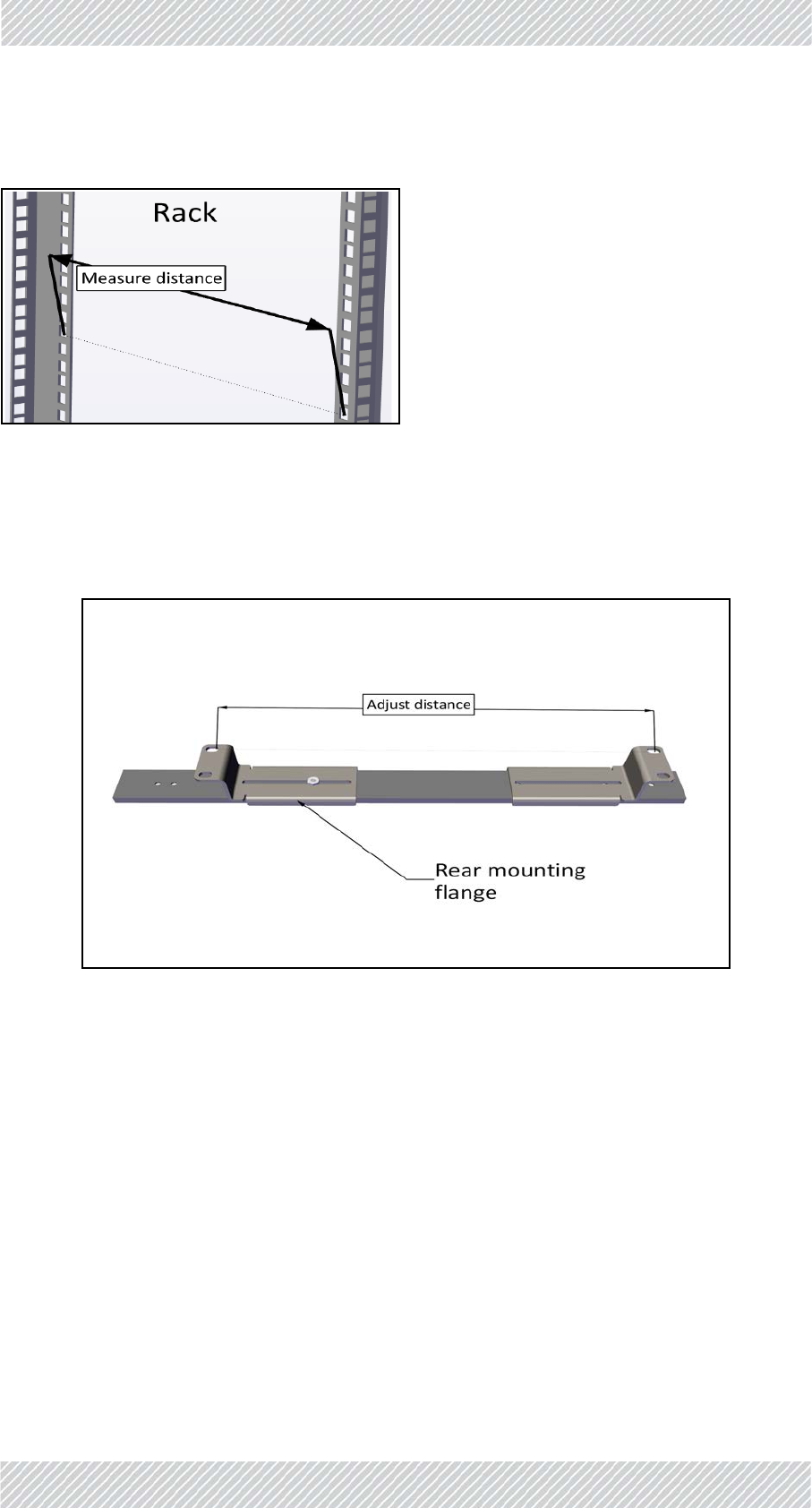
5. Measurethedistancebetweenverticalrailsoftherack.
Figure1‐63:Measuredistancebetweenverticalrails
6. Adjustthelocationoftherearmountingflangeofthefirstmountingslidesothat
thedistancebetweentheholesofthemountingflangesarethesameasthe
distanceyoumeasuredinthepreviousstep.
Figure1‐64:Adjustdistanceofrearmountingflange
For Regualtor Approval Only
FinMDeploymentGuide Release4.2.46 1‐36
TMU SiteInstallation
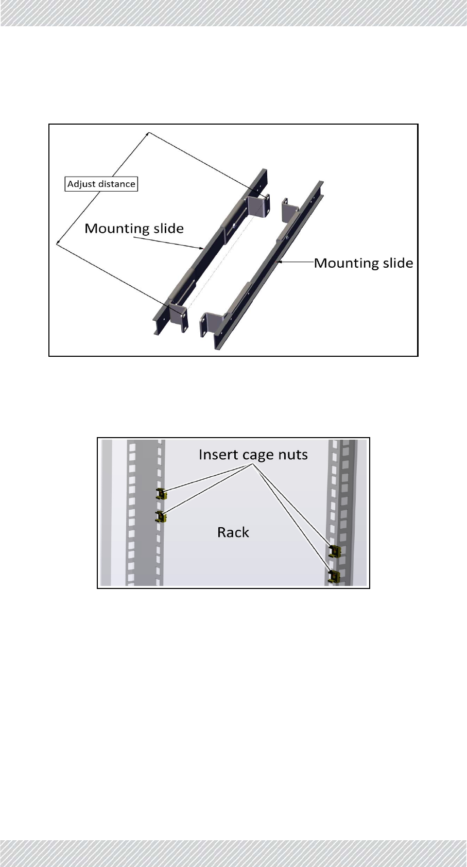
7. Placethesecondslidenexttothefirstandadjustitsrearmountingflangesothat
thedistancebetweentheflangesarethesameasthatofthefirstslide.
Figure1‐65:Adjustdistanceofmountingflangeonsecondslide
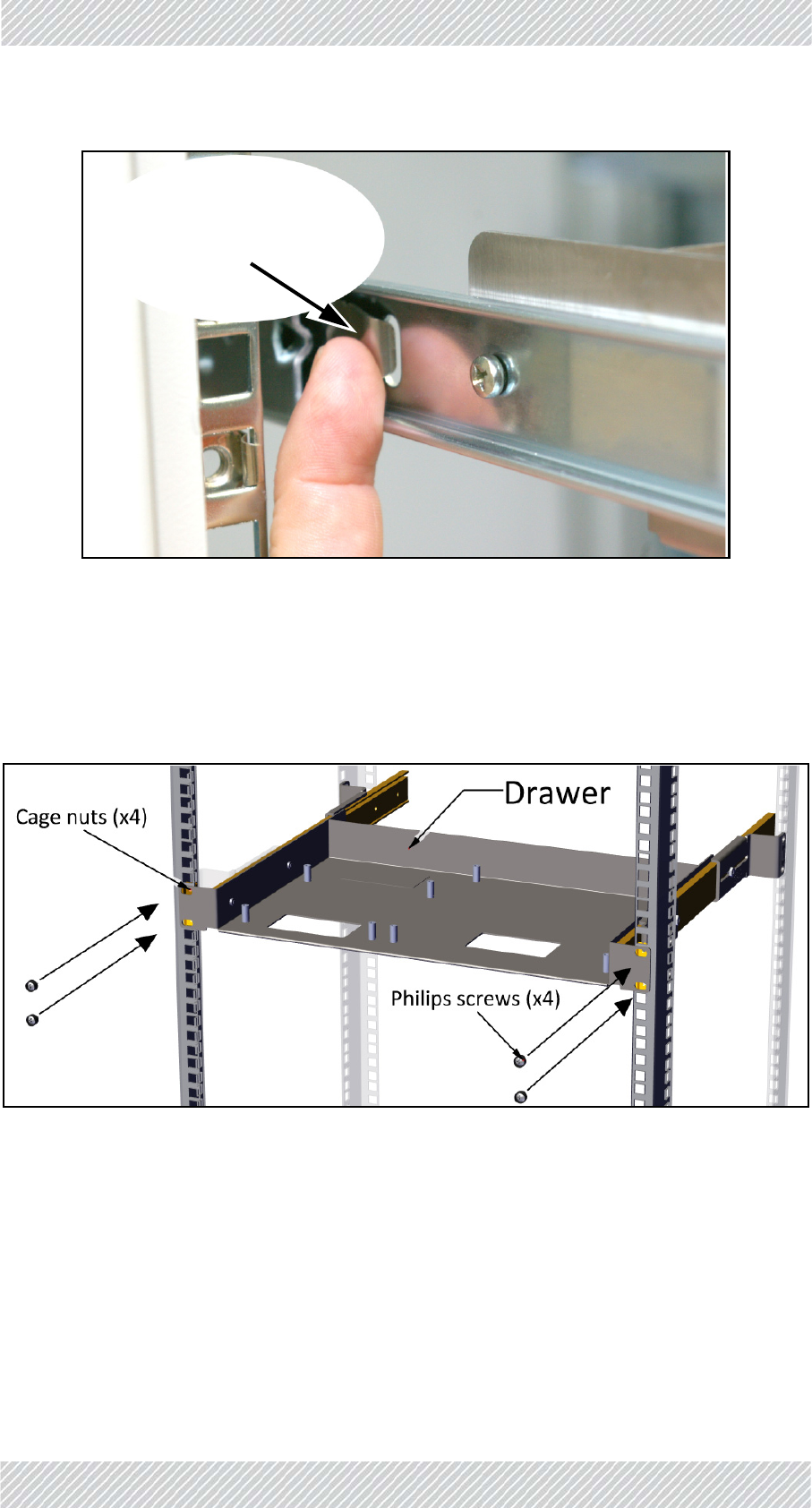
8. Insert8mechanicalcagenutsintheappropriateholesinthe19inrack:4oneach
sideoftherack.
Figure1‐66:Insertingcagenuts(onesideshown)
For Regualtor Approval Only
FinMDeploymentGuide Release4.2.46 1‐37
TMU SiteInstallation
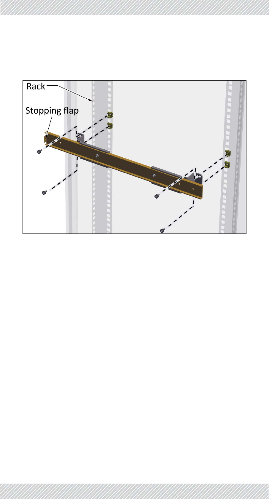
9. Placeeachmountingslidewiththestoppingflaptowardstherearoftherack,and
usingthePhilipsscrewswiththeblackwashers,fastenthemountingslidestothe
cagenutsandtighten.
Figure1‐67:Placingandfasteningmountingslide
10.Oncebothmountingslidesarefastenedtightlyontherack,insertthedraweras
follows:
a. Placetheframeworkarmsofthedrawerintothemountingslidescarefully.Make
suretheyarestraight.
b. Pushbackthedraweruntiltheframeworkarmstouchtheball‐bearinggrey
housing.
c. Whilepressingoutwardsonbothball‐bearinggreyhousings,pushthedrawerin
furtheruntiltheframeworkarmsengagetheball‐bearinghousings.
d. Furtherpushthedraweruntilthelockingleverstopsit.
e. Releasethelockinglevers,andpushthedrawerinalltheway,eventhroughsome
resistancetowardstheend.
For Regualtor Approval Only
FinMDeploymentGuide Release4.2.46 1‐38
TMU SiteInstallation
Figure1‐68:Insertingthedrawer:Placearmsstraight
Figure1‐69:Insertingthedrawer:Pushball‐bearinghousingsoutwards
Pushball‐bearing
housingoutwards
For Regualtor Approval Only
FinMDeploymentGuide Release4.2.46 1‐39
TMU SiteInstallation
Figure1‐70:Insertingthedrawer:Releaselockinglevers
11.Inserttheother4cagenutsintheappropriateholesinthefrontsideofthe
verticalrails.
12.Usingtheother4Philipsscrewswiththeblackwashers,securethedrawertothe
frontsideoftheverticalrailsoftherack.
Figure1‐71:Securedrawertothefrontsideofrack
Presslockinglevers
andpushdrawerin
For Regualtor Approval Only
FinMDeploymentGuide Release4.2.46 1‐40
TMU SiteInstallation
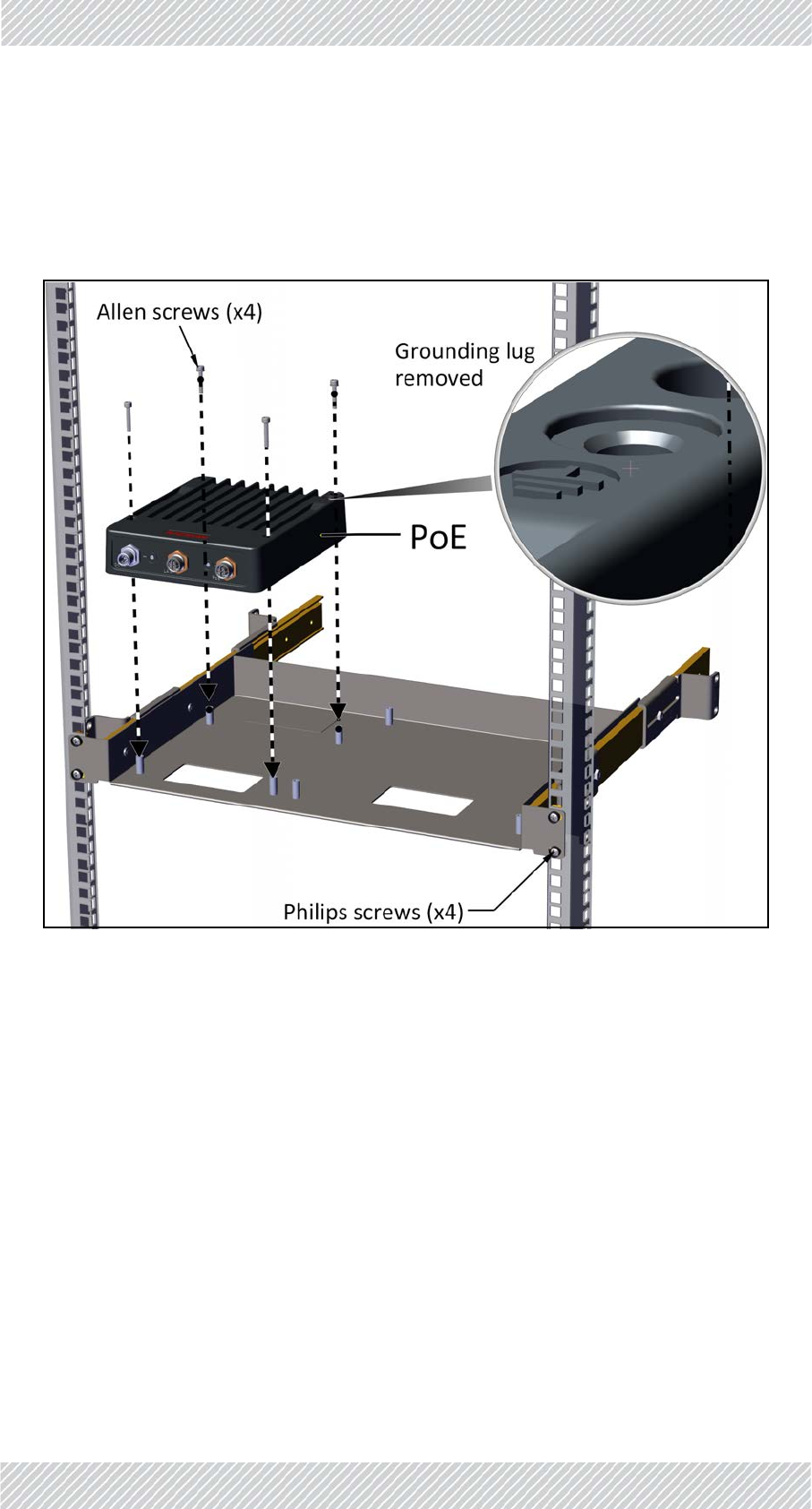
13.AttachPoEandTMUtodrawerasfollows:
a. Removegroundinglugsfrombothunits(theyinterferewiththedrawerandarenot
neededforadrawerinstallation).
b. PlacePoEoverthepinsoftheleftsideofthedrawerasshown,andattachusing
allenscrews.
Figure1‐72:AttachingPoEtodrawer
For Regualtor Approval Only
FinMDeploymentGuide Release4.2.46 1‐41
TMU SiteInstallation
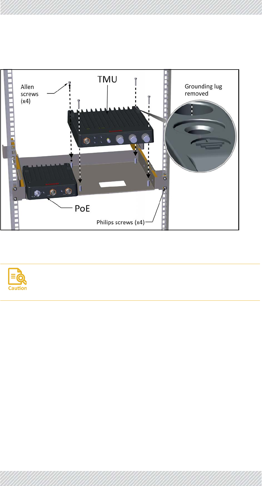
c. PlaceTMUoverthepinsontherightsideofthedrawerasshown,andattachusing
allenscrews.
Figure1‐73:AttachingTMUtodrawer
TheTMUandPoE,whenmountedintheTMU‐PoEdrawer,aregroundedviathe
mountingpins,throughthe19inrack.
Makesuretherackyouareusingisgroundedproperly.
For Regualtor Approval Only
FinMDeploymentGuide Release4.2.46 1‐42
PoEDevicefortheTMU SiteInstallation
Mountingonawall
BoththePoEdeviceandtheTMUcanbemountedonawall.
1. Usescrewsappropriateforthewallsurfaceonwhichtheunitistobemounted.Screwsare
suppliedbythecustomer.
2. MountthePoEdeviceclosetotheTMUsotheDC‐TMUjumpercablecanbeeasily
connected.
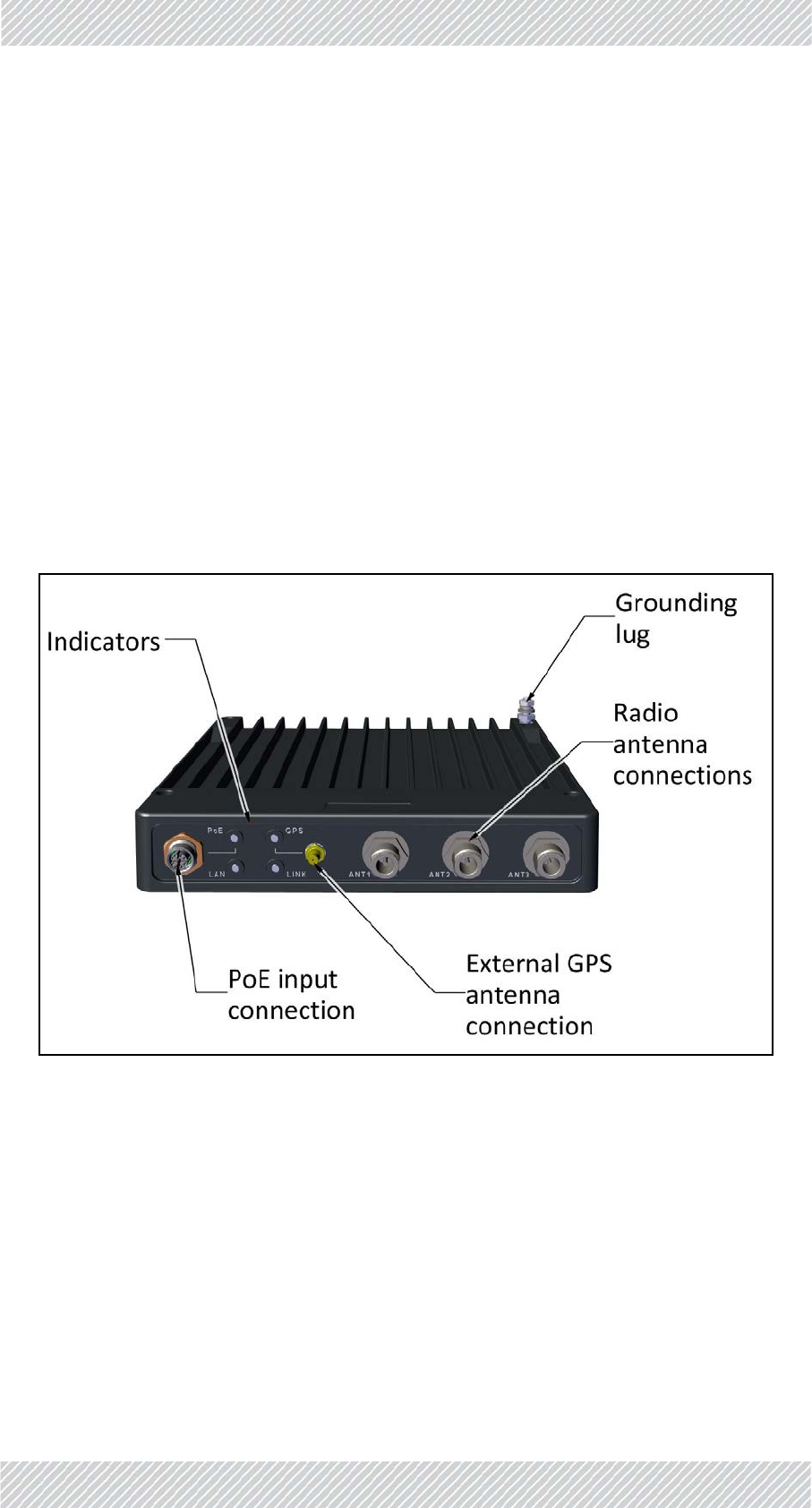
TMU‐ExternalConnections
1. AttachDC‐TMUjumpercabletothePoEinputsocketsontheTMUasshown.
2. Attachantennacablestotheradioantennaconenctions(ANTxsockets)onthe
TMU.
3. Iftheunitisnotmountedina19inrack,attachagroundcabletoitsgroundlug.
4. ToapplypowertotheTMU,attachapowercabletotheDCINportonthePoE
device.Applyvoltage,andtheunitswillbeON.
Figure1‐74:TMU‐ExternalConnections
1.3.2PoEDevicefortheTMU
TheDCPoEdeviceisalwaysmountednexttotheTMU.
Theunitscanbemountedina19inrackoronawall,oronaDINrail.
MountingwiththeTMU‐PoEdrawer
TheTMU‐PoEdrawerisusedtomountboththeTMUandthePoE.Followtheinstructionsin
“Mountingonawall”onpage1‐42.
For Regualtor Approval Only
FinMDeploymentGuide Release4.2.46 1‐43
TMUAntennas SiteInstallation
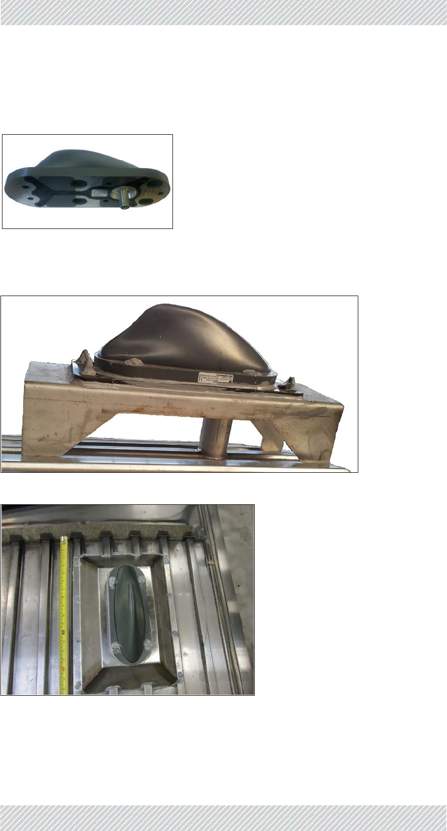
1.3.3TMUAntennas
Eachlocomotiveisfittedwiththree“Shark‐Fin”roofantennasascloseaspossibletothefront
ofthelocomotiveandthecommunicationsrackinthatorderofpreference:
Figure1‐75:“Shark‐Fin”antenna‐bottomview
Toensureasmoothhorizontalmountingsurface,amountingtablemaybeused.Two
variationsareshowninFigure 1‐76andFigure 1‐77below:
Figure1‐76:RoofMountingTableforShark‐Finantenna
Figure1‐77:IntegratedRoofMountingTableforShark‐Finantenna
For Regualtor Approval Only
FinMDeploymentGuide Release4.2.46 1‐44
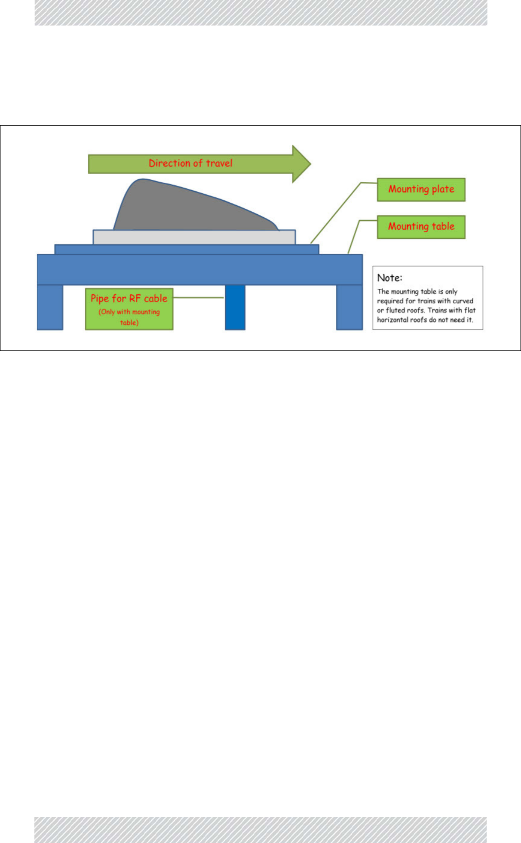
TMUAntennas SiteInstallation
Thescrew,boltandothermoisturepronesurfacesarecoatedwithwaterproofsilicone.The
verticalpipeweldedatitsendstothekitandthetrainroofareconduitsfortheRFcableand
arecompletelywaterproof.
Figure1‐78:Shark‐Finantennainstallationschematicfortablemounting
Ifthetrainroofissufficientlyflatandsmooth,themountingplateisnotneeded.
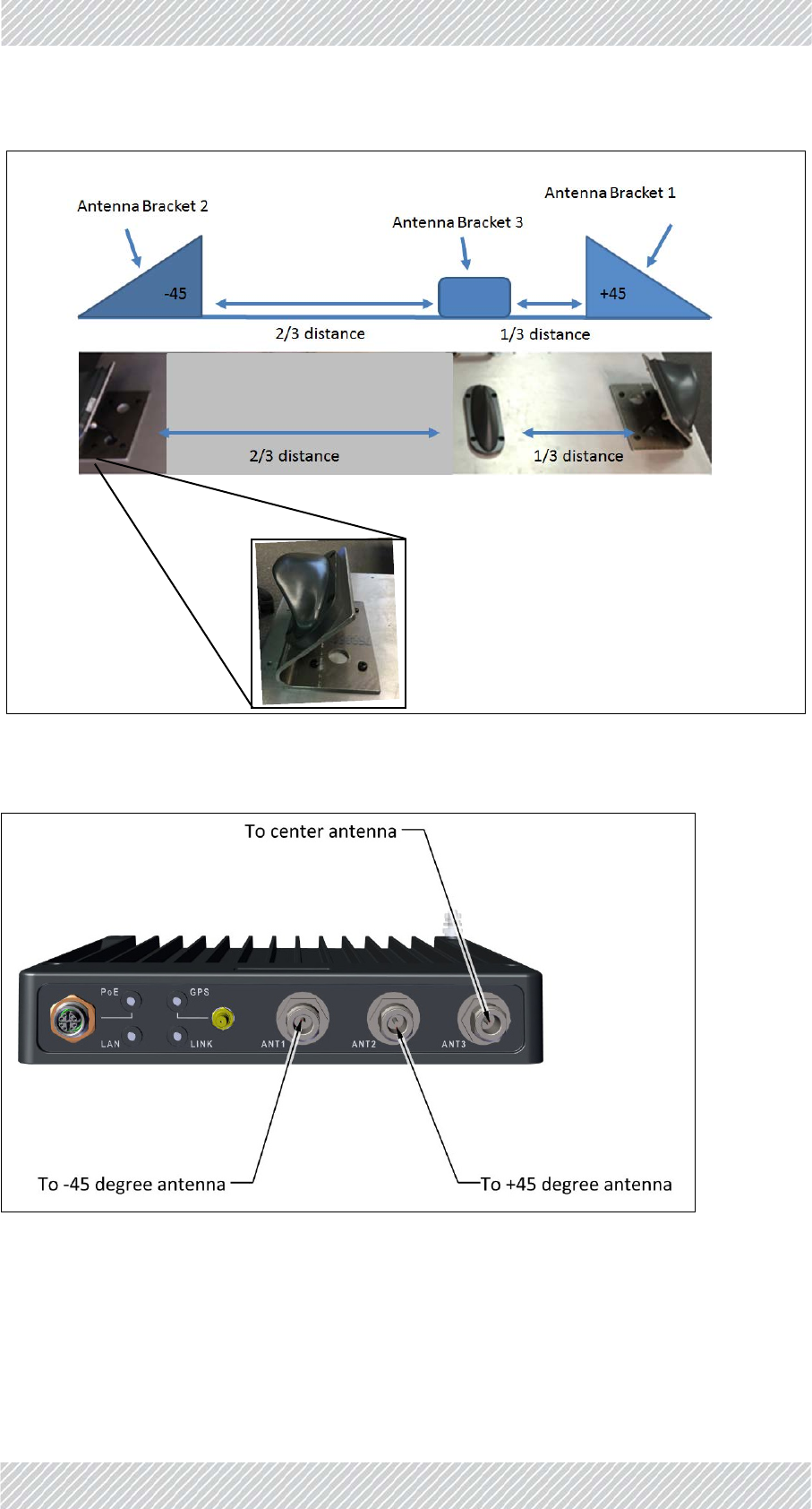
Whatevermountingarrangementisadopted:
•Theantennasshouldbemountedasclosetothefrontofthelocomotiveaspossible,
andnolessthanameterapart.
•Thereshouldnotbeanyobstructionsbetweentheantennasandthefrontofthetrain
suchasair‐conditionerunits,electronicroutenumberdisplayboxesandthelike.
•MountAntenna1andAntenna2ontheedgeofthelocomotiveata45oangle,as
showninFigure 1‐79.
•MountAntenna3(center)ata90oangle(directlyup)andonethirdofthedistance
betweentherightandleftantennasasshowninFigure 1‐79.
•ConnecttheantennaportsoftheTMUtotheantennasasshowninFigure 1‐80.
For Regualtor Approval Only
FinMDeploymentGuide Release4.2.46 1‐45
TMUAntennas SiteInstallation
Figure1‐79:TMUantennamountingconfigurationonroof
Figure1‐80:TMUantennaportconnectionscheme
For Regualtor Approval Only
FinMDeploymentGuide Release4.2.46 1‐46
TMUAntennas SiteInstallation
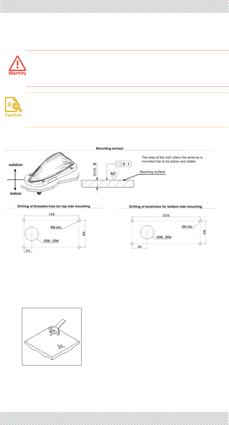
TomountaShark‐Finantenna:
1.PreparethemountingsurfaceasshowninFigure 1‐81below:
Figure1‐81:Preparingthemountingsurface
2.Preparetheroofmountingarea:Cleartheareawheretheantennaistobemounted
frompaint,corrosionoranyanodizedlayer.
3.Useascrapertoclearthisareaofanydust,brakedust,cuttingchips,oilorfatty
material.
4.Ifyouaremountingtheantennaonabracket,mountingplateortable,usean
additionalcableprotectionkit.
•Keepawayfromcatenaryandhighvoltagelines
•Becarefulwhenworkingatheights!
•Alwayssecureladders!
•Alwaystightenscrews!
•ESD(electrostaticdischarge)sensitivedevice.Alwaysgroundyourselfwhile
handlingtheantenna
•Avoidbringingthecoveroftheantennaintocontactwithacetone,gasolineor
oil
For Regualtor Approval Only

FinMDeploymentGuide Release4.2.46 1‐47
TMUAntennas SiteInstallation
5.Toconnectagroundingcable,anadditionalgroundingkitshouldbeused.
.
Figure1‐82:Installationonbracketortable:Cableconduitandgroundingkit
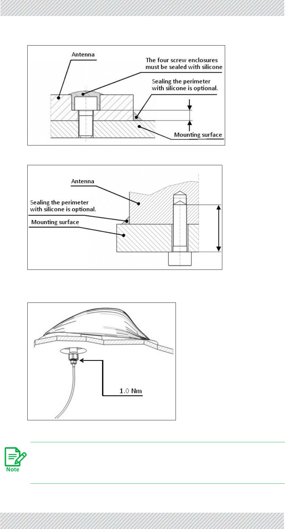
6.Mounttheantennatothemountingplateorroof.Therearetwomethodsasshown
inthenexttwodiagrams:
Figure1‐83:Bottomsidemounting
Figure1‐84:Topsidemounting
7.Sealthescrewenclosuresandperimeterwithsilicone.Therearetwomethodsas
showninthenexttwodiagrams:
For Regualtor Approval Only
FinMDeploymentGuide Release4.2.46 1‐48
TMUAntennas SiteInstallation
Figure1‐85:Sealingtopsidemounting
Figure1‐86:Sealingbottomsidemounting
8.ConnecttheRFcableasshownbelow:
Inthefinalpositioningoftheantenna,thedrainingholeandtheconnectorsmust
beprotectedagainstenvironmentalimpact.Otherwiseacableconduitshouldbe
used.
For Regualtor Approval Only

FinMDeploymentGuide Release4.2.46 1‐49
TMUAntennas SiteInstallation
For Regualtor Approval Only

FinMDeploymentGuide Release4.2.46 2‐1
Chapter2:NetworkGuidelines
2.1ScopeofThisChapter
ThischapterprovidesadescriptionofthetypicalnetworkingtopologyrequiredbyRADWIN's
FiberinMotionTrain‐To‐Groundsolution.
2.2Overview
Includedinthischapterare:
•Ageneralintroductiontothenetworkrequirementsfortracksideandon‐boardnet‐
works,
•Adescriptionoftherequiredrouters'functionalities,
•Adataflowdescription,
•SampleIPandVLANassignmentguidelines,
•Ashortdescriptionoftheupdatemessagesduringhandovers,andhowtherecom‐
mendednetworktopologysupportsthesemessages.
ThetypicalnetworkingdescribedinthischapterenablesbroadbandTrain‐To‐Ground
communication,whilemaintainingahandovertimeoflessthan50ms.
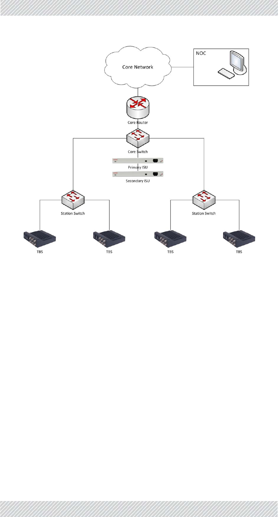
2.3TrackSideNetwork
TheRADWINFiberinMotionsolutionisbasedonatransparentlayer2architecture:
•ThebackhaulnetworkisconnectedtotheRadioBaseStations(TBS)deployedalongthe
trackssideviaGbEcopperorfiber,asalayer2basednetwork.
Followtheguidelinescarefully.Anyquestionsorclarificationsshouldbe
addressedtoRADWIN'sProfessionalServicesteamforanofficialresponse.
Priortoprojectrollout,adetailednetworkarchitecture(includingtopologyand
HWtobeused)shouldbesharedwithRADWINforconfirmation.
For Regualtor Approval Only

FinMDeploymentGuide Release4.2.46 2‐2
TrackSideNetwork NetworkGuidelines
•Thebackhaulnetwork(existingorprovidedbythesystemintegrator/customer)isused
toaggregatetrafficto/fromtheTBSsandsendittothecontrol/datacentres.
•Therequirednetworkarchitecturemusthaveasinglecorerouter,andL2switches.All
datacommunicationto/fromthetrainwillpassviathisrouter.
•AredundantISUisprovidedtoensurehigherresiliencyofthesolution.
•TheTBS'snetworkissynchronizedeitherviaGPS‐basedsystem(forabovegroundsce‐
narios)orviaEthernet‐basedsynchronization(foraboveorundergroundscenarios).
•ForGPSbasedsynchronization,theTBSintegratedGPSSynchronizationUnitisused.
•ForEthernet‐basedsynchronization,theTBS'snetworkwillbesynchronizedbyEthernet
basedsynchronization,runningoverthesamedatabackhaulnetwork.Theimplementa‐
tionofthesynchronizationprotocolisviaanIndoorSynchronizationUnit‐ISU(pro‐
videdbyRADWIN),thatisconnectedtooneofthenetworkswitches,andprovidesthe
masterclocktoallTBSsinthenetwork.
•Thesynchronizationarchitecturemayvarydependingonthespecificnetworktopology,
soRADWINneedstoevaluateandapprovethetracksidenetworktopologyandassureit
willsupportthesynchronizationprotocol.Typicalsynchronizationrequirements
include:
•Layer2connectionbetweenallISUsandTBSs.
•Maximumof4switchesbetweenISUsandeachTBS.
•Avoidhighlinespeedutilizationtopreventintroductionofjitterandlatency.The
lineloadshouldbelimitedaccordingtothefollowingtable:
•Networkswitchesshouldappropriatelyhandlethesystem'srelearningframes.These
framesareVLANtagged(802.1Q).Switchshouldforwardtherelearningtrafficand
updateFIB(ForwardingInformationBase).(Seechapters9&10formoreinformation
ontheupdatemessages).
•IEEE802.3azmustbedisabledonallswitches.
•Spanningtreebetweentrainandtracksideisnotsupportedandmustbedisabledon
switchportsconnectedtotheradios.
•Staticroutingshouldbeimplementedbetweentracksidecorerouterandon‐board
routers.ImplementationofdynamicroutingprotocolsshouldbeconfirmedwithRAD‐
WINprofessionalservices.
Table2‐1:ISU‐TBSswitchesvs.lineutilization
NumberofSwitchesBetweenISUandTBS MaximalLineUtilization
195%
285%
3 75%
465%
For Regualtor Approval Only
FinMDeploymentGuide Release4.2.46 2‐3
TrainSide(On‐board)Network NetworkGuidelines
Figure2‐1:Typicaltracksidenetworkarrangement
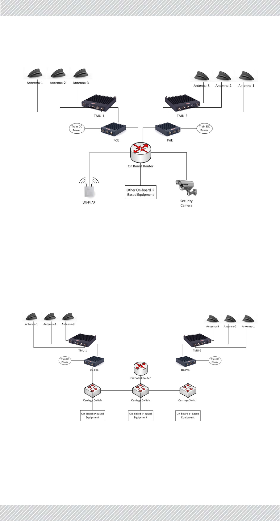
2.4TrainSide(On‐board)Network
•AMobileRadiounit(TMU)isdeployedateachendofthetrain.Itisconnected,viaa
PoE,tothetrain'sinternalnetwork(TrainnetworkisresponsibilityofSI).Thistopology
enableson‐boardredundancyandimprovedperformancebyanIntra‐TrainHandover
mechanism(ITHO).
•L2connectivityisrequiredbetweenbothTMUs
•TMUsandtrainroutershouldbeonthesameIPsubnet
•Trainequipment(APs,CCTVcameras,PISdevicesetc.)shouldbeonadifferentsubnet
fromthatoftheTMU
•Allofthetrain'strafficissentviaanon‐boardrouter(providedbySI)totheactiveTMU
providingthehighestthroughput(whichTMUisconsidered“active”isautomatically
determinedbythesystem).
•Theon‐boardtrainnetworkshouldsupportVLANs
•Networkswitchesshouldappropriatelyhandlethesystem'srelearningframes.These
framesareVLANtagged(802.1Q)andswitchshouldforwardtherelearningtrafficand
updatetheFIB(ForwardingInformationBase)
•IEEE802.3azshouldbedisabledonallswitches
For Regualtor Approval Only
FinMDeploymentGuide Release4.2.46 2‐4
TrainSidePhysicalConnectivity NetworkGuidelines
•Spanningtreebetweentrainandtracksideisnotsupportedandmustbedisabledon
switchportsconnectedtotheradios.
Figure2‐2:Typicaltrainsidenetwork(logicalconnectivity)
2.5TrainSidePhysicalConnectivity
Figure 2‐3presentsanexampleofatypicalphysicalconnectivitywithinanon‐boardnetwork.
On‐boardroutermustbeconnectedthrough1physicalport,butthisportmustsupportat
least2subinterfaces(routeronastick/onearmedrouterimplementation).Eachsub
interfacemusthaveitsownIPaddressandVLANtoenabletheIPschemedetailedinSection
2.7,below.
Figure2‐3:Typicaltrainsidenetwork(physicalconnections)
For Regualtor Approval Only

FinMDeploymentGuide Release4.2.46 2‐5
TrackSideCoreRouter NetworkGuidelines
2.6TrackSideCoreRouter
ThetracksidenetworkrequiresacorerouterthatwillactasthegatewaybetweentheTrain‐
To‐Groundsystemandtheclient'scorenetwork.Alltrafficbetweenanytrain'son‐board
devicesandtheclient'scorenetworkmustpassthroughthisrouter.Thetracksidecorerouter
musthaveatleast2interfaces(seediagrambelowinSection2.7):
Interface1:Connectstotheclient'scorenetwork.Itwillbeonthesamesubnetasthe
client'snetworkandwillbethegatewayforalltrafficfromtheclientnetwork
targetedatdevicesonboardtrains.
Interface2:UsedfortheTrain‐To‐Groundnetwork.Itwillbeonthesamesubnetastheon‐
boardrouterinterface1andwillbethegatewayforalltrafficfromtheon‐
boardroutersonallthetrains.
Alltrafficbetweenanyon‐boarddeviceandthetracksidemustpassthroughtheon‐board
router.
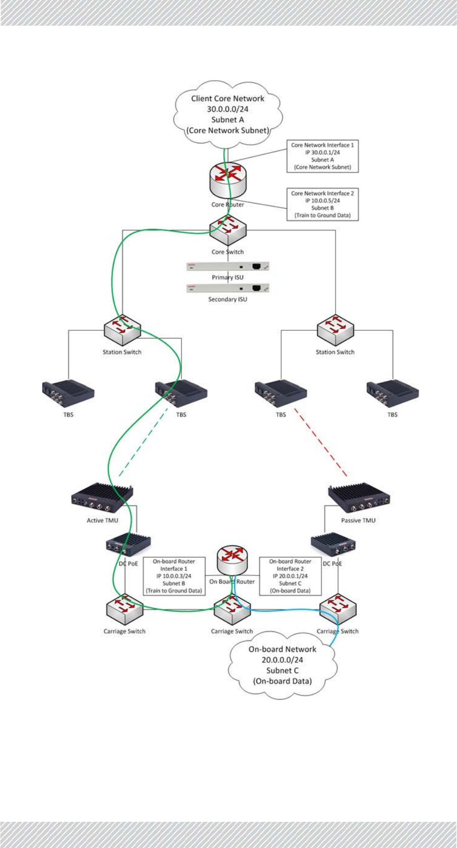
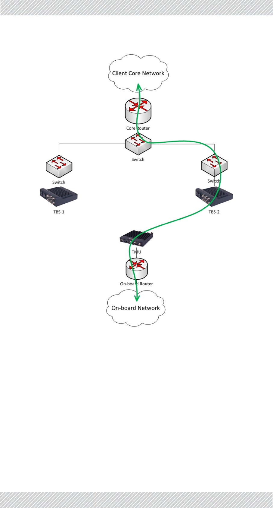
2.7BasicIPSchemeandDataFlowPath
AnexampleofthebasicIPschemeisshownhere.
Thetrafficflowsbetweenthetracksidecorerouterandtheon‐boardrouter.Allelements
betweentherouters(includingswitchesandFiberinMotionradios)arepureL2devices.They
haveanIPaddressformanagementonly,andaretransparenttothedatatraffic.
Overall,atleast3IPsubnetsarerequired:
•SubnetAfortheclientcorenetwork.
•SubnetBforthetraintogroundsegment.
•SubnetCfortheon‐boardnetwork.
For Regualtor Approval Only
FinMDeploymentGuide Release4.2.46 2‐6
BasicIPSchemeandDataFlowPath NetworkGuidelines
Figure2‐4:BasicIPSchemeandDataFlow
For Regualtor Approval Only

FinMDeploymentGuide Release4.2.46 2‐7
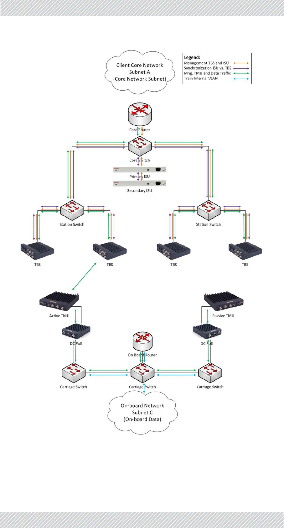
RecommendedVLANAssignment NetworkGuidelines
2.8RecommendedVLANAssignment
AtypicalVLANassignmentthroughoutthenetworkwouldincludethefollowing:
•VLANV1‐ForTBSandISUmanagement
•VLANV2‐Fortracksidesynchronization(BetweenISUandTBSs)
•VLANV3‐For:
•Usertraffic(betweentracksidecorerouterandon‐boardrouter)
•TMUmanagement
•Signallingbetweentwoon‐boardTMUs(tosupportintratrainhandoverindual
TMUpertraindeployment)
•VLANV4‐Trainon‐boardinternalnetwork(foralltrainenduserdevices‐enduserAPs,
IPcameras,IPphones,etc.)
For Regualtor Approval Only
FinMDeploymentGuide Release4.2.46 2‐8
RecommendedVLANAssignment NetworkGuidelines
Figure2‐5:VLANAssignment
For Regualtor Approval Only

FinMDeploymentGuide Release4.2.46 2‐9
InterBaseHandover(IBHO)UpdateMessage NetworkGuidelines
2.9InterBaseHandover(IBHO)Update
Message
Asmentioned,FiberinMotionprovidesL2connectivity,soallL3features(routingetc.)are
handleddirectlybetweentheon‐boardrouterandthetracksidecorerouter.Theadvantage
ofthismodeofoperationisthatnoroutingupdatesareneededduringhandovers,facilitating
thecontinuousfasthandoversneededasthetrainmovesalongthetrack.
However,therewillbeotherL2devices(switches)alongthetracksidenetworkthatmustbe
updated.
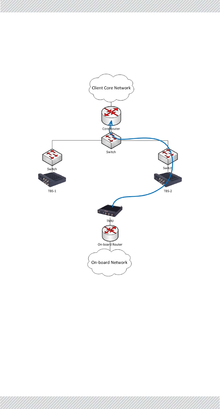
WhenaTMUmovesfromoneTBStothenext,theremustbeanupdateofthetrackside
networksotheswitchesknowthenewdatapath.Thisupdateismadebysendinganupdate
messagetothetracksidecorerouter.However,wedonotwishtosendanupdatemessage
foreachon‐boarddevice.Thiswilloverloadthesystem.Forthisreason,theupdateissent
regardingonly1device‐theMACaddressoftheon‐boardrouter(sincealltheon‐board
devicesarebehindit,theydonotneedtohaveindividualupdatemessagessent).
For Regualtor Approval Only
FinMDeploymentGuide Release4.2.46 2‐11
InterBaseHandover(IBHO)UpdateMessage NetworkGuidelines
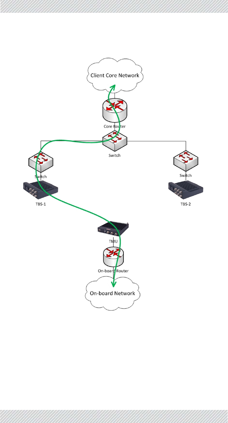
WhentheTMUhasmadeadecisiontoswitchfromTBS‐1toTBS‐2(basedonRSSthresholds)
itinitiatesanupdatemessage(showninblueinFigure 2‐7)tothetracksidecorerouter,with
thesourceMACaddressoftheon‐boardrouter.
Allswitchesalongthetracksidenetwork'snewdatapatharethenupdated.
Figure2‐7:IBHO‐Part2
Asaresult,theTMUisconnectedtoTBS‐2andalltrafficflowsinthenewpath(shownin
greenin.
For Regualtor Approval Only
FinMDeploymentGuide Release4.2.46 2‐12
IntraTrainHandover(ITHO)UpdateMessage NetworkGuidelines
Figure2‐8:IBHO‐Part3
2.10IntraTrainHandover(ITHO)Update
Message
ParalleltotheInterBaseHandover(IBHO)process,describedabove,FiberinMotionalso
supportsanIntraTrainHandover.
TheITHOfeature,implementedintheTMUs,enablesextendedcoverageandthroughput.As
mentionedabove(seeTrainSide(On‐board)Networkonpage 2‐3)thismoderequires2on‐
boardTMUs(ideallyateachendofthetrain),withL2connectivitybetweenthem.
For Regualtor Approval Only
FinMDeploymentGuide Release4.2.46 2‐13
IntraTrainHandover(ITHO)UpdateMessage NetworkGuidelines
ThisprocesshappensinparallelandindependentlyfromtheIBHO.Thebackgroundprocess
consistsofacontinuousevaluationbetweenthe2on‐boardTMUs,astowhichcanreceive
thehigherthroughput(regardlessofwhichbasetheyareconnectedto).
WhenanITHOoccurs,anupdatemustalsobesenttotheon‐boardrouter.Thisupdatewill
refreshtheswitchesalongthenewdatapathastothenewactiveTMU.
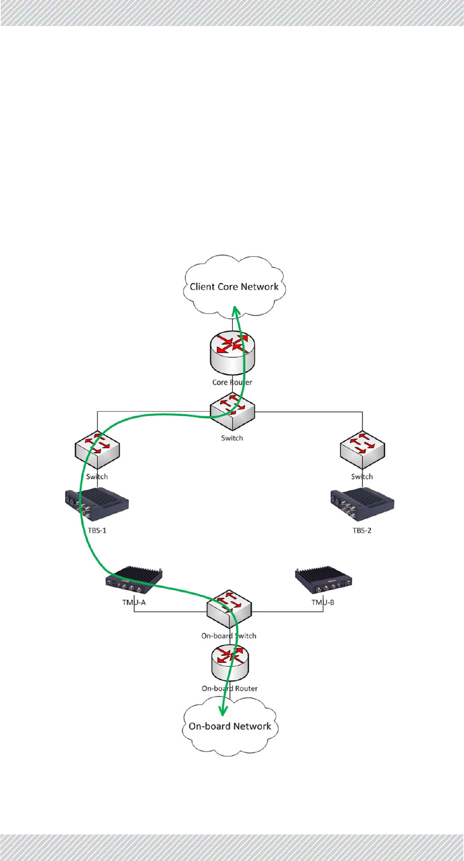
ConsiderFigure 2‐9whereitisshownthatTMU‐AisconnectedtoTBS‐1andisACTIVE
(passingtraffic).Alltrafficflowsinthegreenpath.
TMU‐BisPASSIVE.IthasanidleconnectiontoaTBSanditmonitorsthepotentialthroughput,
butdoesnotpasstraffic.
Figure2‐9:ITHO‐Part1
For Regualtor Approval Only
FinMDeploymentGuide Release4.2.46 2‐14
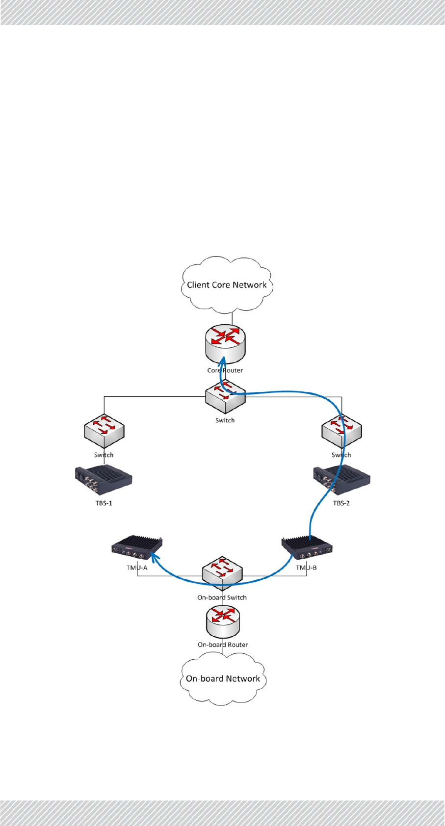
IntraTrainHandover(ITHO)UpdateMessage NetworkGuidelines
TheIntraTrainHandovermechanismdiscoversthatahigherthroughputcanbeachieved
throughTMU‐B,definedatpresentasPASSIVE.(TMU‐BmaybeconnectedtothesameTBSas
TMU‐Aortoadifferentone‐thisdoesnotaffecttheITHO).
AnITHOisthereforeinitiatedandTMU‐Bisre‐definedasACTIVE.TMU‐Bthensends2update
messages(markedinblueinFigure 2‐10):
•Updatemessagetotracksidecorerouterwithon‐boardrouterMAC‐toupdatethe
tracksideL2networkofthenewdatapath(sameprocessasintheIBHOupdate
describedabove)
•UpdatemessagetotheotherTMU(TMU‐A)withthetracksidecorerouterMAC‐to
updatethetrainL2networkofthenewdatapath.
Figure2‐10:ITHO‐Part2
For Regualtor Approval Only
FinMDeploymentGuide Release4.2.46 2‐15
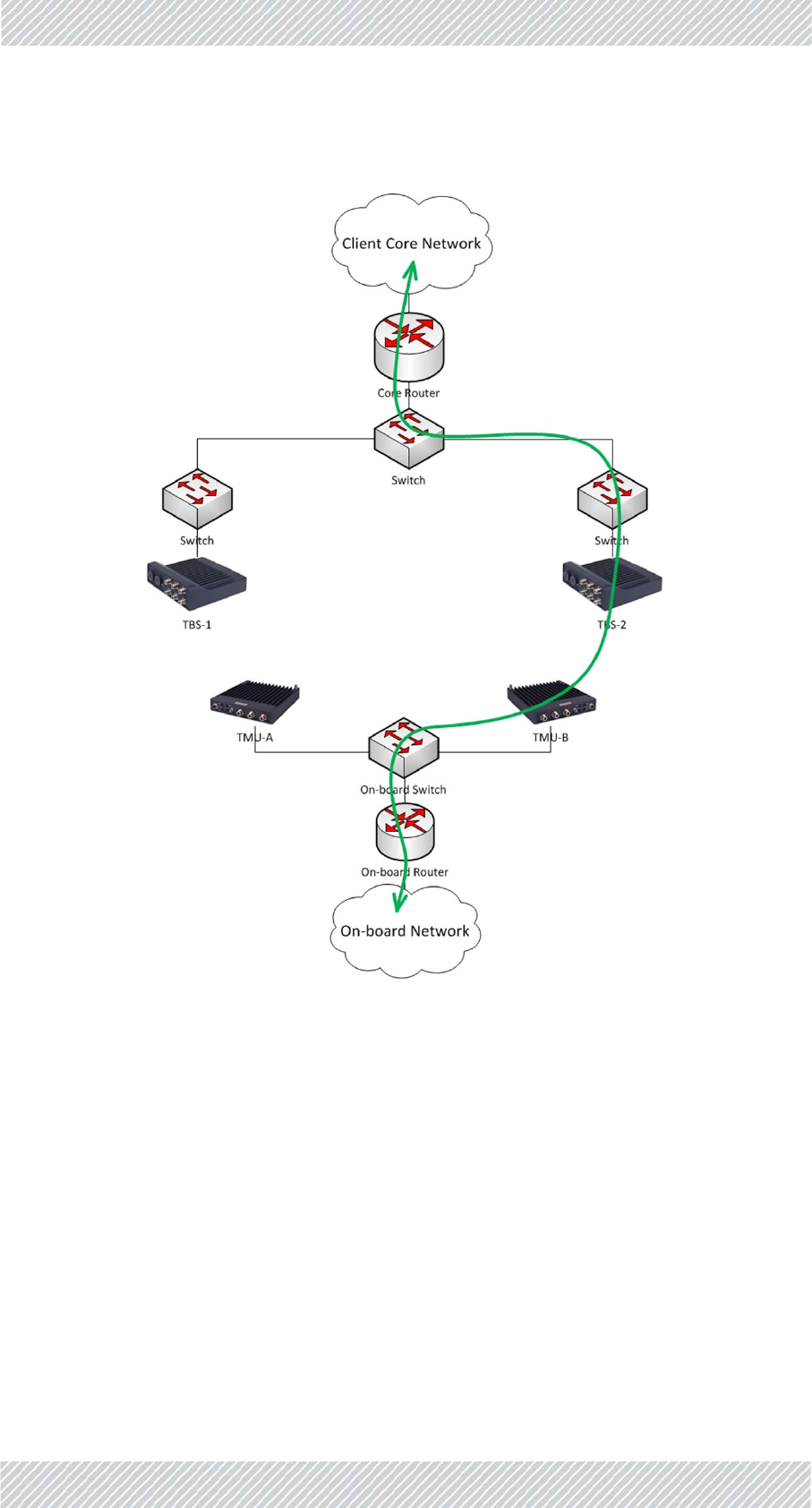
IntraTrainHandover(ITHO)UpdateMessage NetworkGuidelines
Allon‐boardtrafficnowflowsthroughTMU‐BtoTBS‐2inthenewgreenpath:
Figure2‐11:ITHO‐Part3
For Regualtor Approval Only

FinMDeploymentGuide Release4.2.46 3‐1
Chapter3:Configuringthe
RadioNetwork
3.1ScopeofThisChapter
ThischaptershowshowtoworkwiththeConfigurator,andprovidesafewexamplesofsome
parameters.Italsoincludessometipsandadviceforbestpracticeswhenworkingwiththe
Configurator.
3.2ConnectingtotheUnits
Forafirsttimeconfiguration,allunitsaresettoanIPaddressof10.0.0.120withsubnetmask
255.0.0.0.ThelaptopEthernetcardshouldbesettoafreeIPaddressonthatsubnet(for
example10.0.0.111).
AlloftheTBSsandanyISUsneededmustbephysicallyinstalledbeforeyoucanworkwiththe
Configurator.
3.3AbouttheConfigurator
TheConfiguratorisusedtoconfigureeachactivedeviceusedinyourproject:TMUs,TBSs,
andISUs.YoualsousetheConfiguratortosetmanygeneralparametersincludingIPaddress
details,gateways,frequenciesandbandwidths,andmuchmore.
ISUsarerequiredonlyinanenvironmentthatdoesnothaveaccesstoaGPSsignal
(tunnels,stations,etc.)
TousetheConfiguratoryoumusthaveMSExcel2007orlaterinstalledonyour
laptop(s).
For Regualtor Approval Only

FinMDeploymentGuide Release4.2.46 3‐2
MethodofOperation ConfiguringtheRadioNetwork
TheConfiguratorisanExcelfilethatconsistsoffivetabs:
Main: Providesanoverviewofthecontentsoftheproject,aswellasvariousbuttonsfrom
whichyoucanconfigurespecificdevices.SeeMainTab.
Project:Allowsyoutoentervariousproject‐wideparameters,suchasthefrequenciesand
bandwidthsused,synchronization,units’power,QoS,VLAN,andEthernetmode,
andmore.SeeProjectTab.
Line:AllowsyoutoentertheIPaddressesofthevariousdevicesandgatewaysused,VLAN
definitionsandmore.SeeLineTab.
Towers: AllowsyoutoentertheIPaddressesofthevariousTBSsintheprojectinadditionto
theirneighbors.SeeTowersTab.
Trains:AllowsyoutodefinetherailcarsthatwillbeintheprojectandtheirTMUs.SeeTrain
Tab.
3.3.1MethodofOperation
Briefly,workwiththeConfiguratiorfileasfollows:
•ChangewhatevervaluesneedtobechangedusingtheConfiguratorfile,
•ClickonRecalcalldata(ifneeded:seepage 3‐5),then
•Savethefile.
•Oncethefileissaved,applythevaluesusingeithertheConfigureUnitbutton(see
page 3‐4),ortheHBSBatchConfigurationbutton(page 3‐4).
TheConfiguratorwillconnectwiththeunits,andapplythechanges.
3.4UsingtheConfigurator
ClickonthedesktopicontostarttheConfigurator.Thefilewillopen,andtheMaintabwill
appear.
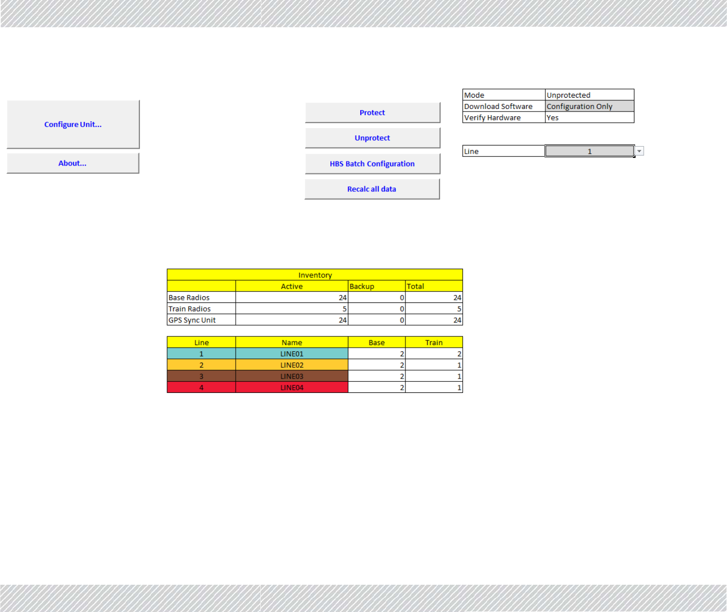
3.4.1MainTab
TheMaintabisshowninFigure 3‐1:
For Regualtor Approval Only
FinMDeploymentGuide Release4.2.46 3‐3
MainTab ConfiguringtheRadioNetwork
Figure3‐1:Configurator‐Maintab
Tableontopright:
For Regualtor Approval Only

FinMDeploymentGuide Release4.2.46 3‐4
MainTab ConfiguringtheRadioNetwork
Setitemsinthistablefirst,beforecarryingoutanyothertasksonthistab.
Figure3‐2:Maintab:Pre‐Conditions
Mode:ShowsthemodeoftheConfigurator(ProtectedorUnprotected)
Downloadsoftware:
DeterminesworkingdetailsoftheConfigureUnitandHBSBatchConfiguration
buttonsasfollows:
NomeansthatchangesyoumakeusingtheConfigureUnitorHBSBatch
ConfigurationbuttonswillaffectthisConfiguratorfileonly,andwillnotbe
downloadedtoanyunits.
ConfigurationOnlymeansthatthechangesyoumakeusingtheConfigureUnit
orHBSBatchConfigurationbuttonswillaffectthisConfiguratorfileandwillbe
downloadedtotherelevantunits.Youmustmakesurethattheradiounitsin
usehavetherequiredfirmwareinstalledonthem.
Configuration&Releasemeansthatthechangesyoumakeusingthe
ConfigureUnitorHBSBatchConfigurationbuttonswillaffectthisConfigurator
file,thesystemwillthencheckiftherelevantradiounitsneedafirmware
updateandifso,willupdatethem,andonlythenwilldownloadthechanges
youhavemadetotherelevantunits.
Compare/Verifyinstructsthesystemtocomparetheconfigurationofthe
relevantunitsasopposedtotheconfigurationasshowninthefileasitisat
present(itrelatestotheopenExcelfile,andnotthefilesavedondisk).
VerifyHardware:Notforcustomeruse.
Line:Indicatesforwhichlineyouaremakingconfigurationchanges.Thisaffectsany
changesyoumakeusingtheConfigureUnitorHBSBatchConfigurationbuttons.
ConfigureUnit:ClicktoopentheConfiguratordialogbox.Thisenablesyoutoconfigure
individualunits,oneatatime.Thelineshownisdeterminedbythevaluein
theLinewindow.SeeConfiguringNetworkUnits.
About... ClicktoopenawindowshowingthesoftwareversionoftheConfigurator
application.
Protect ClicktoprotecttheConfiguratorfilefrombeingchanged.
Unprotect ClicktoallowtheConfiguratorfiletobechanged.Password:psfiberinmotion
HBSBatchConfiguration:
For Regualtor Approval Only

FinMDeploymentGuide Release4.2.46 3‐5
ProjectTab ConfiguringtheRadioNetwork
Onceyouhavemadechangesinthisfile,recalculatedanyneededvalues,and
savedthefile,clickthisbuttontoapplythosechangestoalloftheTBSs,
insteadofjustoneatatime.Acommandlineinterfacewindowwillopen,and
theupdatestatusofeachunitwillbeshown.
Changesforonlyonelinearedone,asdeterminedbythevalueintheLine
window.
Recalcalldata:Afteryouhavemadechangestovariousparametersasdescribedthroughout
thischapter,beforeapplyingthemtoanyunits,clickthistore‐calculateall
otherparametersthatmayhavebeenaffectedbyyourchanges.Thisdoesnot
applyanychangestoanyunits.
LowerTable:Providesanoverviewoftheequipmentandlinesusedinthewholeproject.
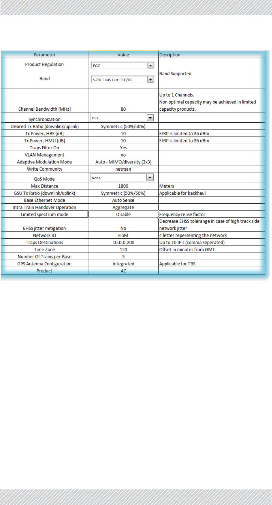
3.4.2ProjectTab
TheProjecttabholdsgeneralconfigurationparametersthatapplyacrosstheproject.
UpperTable
TheuppertableoftheProjecttabisshowninFigure 3‐3:
For Regualtor Approval Only
FinMDeploymentGuide Release4.2.46 3‐6
ProjectTab ConfiguringtheRadioNetwork
Figure3‐3:Configurator‐Projecttab,uppertable
Band:Clickthispull‐downmenutochoosethefrequencybandtobe
usedfortheproject.Onlythosebandsthatareinaccordance
withyourregulatoryenvironmentwillappear.
ChannelBandwidth: Clickthispull‐downmenutochoosethebandwidthtobeused
forthisproject.ThefrequenciesusedintheTowertab(F1,F2,
F3,etc)willbethebasefrequencychoseninBand,withthe
bandwidthadded.
Notethatnotallfrequencybandsallowallbandwidthstobe
used.
Synchronization: Clickthispull‐downmenutochoosethetypeofsynchronization
usedinthisproject:
IntegratedGPS:UseaGPSunitintegratedintheTBS.Usedin
abovegroundscenarios.
For Regualtor Approval Only

FinMDeploymentGuide Release4.2.46 3‐7
ProjectTab ConfiguringtheRadioNetwork
GSU:UseanexternalGPSunit.Usedinabovegroundscenarios.
Notethatthisrequiresextrainstallationandconfigurationfor
theGSU.
ISU:UsetheIndoorSynchronizationUnit.Usedinbelowground
scenarios.
None:Donotusesynchronization
DesiredTxRatio
(downlink/uplink):
Symmetric(50/50):Usethisifthereisnosignificantdifference
inthetransmissionconditionsbetweenTBS‐>TMUandTMU‐
>TBS.
MaxUplink(20/80):Usethisifyourprojectrequirestheuplink
(TMU‐>TBS)tobemuchstrongerthanthedownlink(TBS‐
>TMU).
Uplink(30/70):Usethisifyourprojectrequirestheuplink(TMU‐
>TBS)tobestrongerthanthedownlink(TBS‐>TMU).
Downlink(70/30):Usethisifyourprojectrequiresthedownlink
(TBS‐>TMU)tobestrongerthantheuplink(TMU‐>TBS).
MaxDownlink(80/20):Usethisifyourprojectrequiresthe
downlink(TBS‐>TMU)tobemuchstrongerthantheuplink
(TMU‐>TBS).
TxPower,HBS[dB]: Setthevaluethatwillgiveyouthebestthroughputwiththe
leastnoise.Maximumradiatedoutputpowershallnotexceed
36dBmEIRP(FCCregulatoryenvironments).
TxPower,HMU[dB]: Setthevaluethatwillgiveyouthebestthroughputwiththe
leastnoise.Maximumradiatedoutputpowershallnotexceed
36dBmEIRP(FCCregulatoryenvironments).
TrapsFilterOn: Enablethistofilterthetrapstothosethatarerelevantforyour
project.Ifthisisnotenabled,theneverychangeortrap‐not
matterhowtrivial‐willberecorded,andyourtrapslistwill
quicklybecomeverylargeandcumbersome.
Werecommendtoenablethisparameter.
VLANManagement: EnableifyourprojectisusingaVLAN.
For Regualtor Approval Only

FinMDeploymentGuide Release4.2.46 3‐8
ProjectTab ConfiguringtheRadioNetwork
AdaptiveModulation
Mode:
MIMO:(Multi‐In,Multi‐Out)Setthetransmissionmethodtouse
onedatastream,butmultipledatasignals.Thisisusefulinaless
noisyenvironmentthatrequiresahighercapacity,butwhere
dropswillnotlikelyoccur,suchaswhenthetrainisstoppedata
station.
Diversity:Setthetransmissionmethodtousemorethanone
datastream.Thisisusefulwhenthetrainistravellinginanoisy
environmentorwhendropsarelikelytooccur,suchasduring
fastmovement.
AutoMIMO/Diversity:Setthesystemtoautomaticallydetect
theconditionstoswitchbetweenMIMOandDiversity.
WriteCommunity: Setthelinkpasswordhere.
QoSMode: QualityofService(QoS)isatechniqueforprioritizationof
networktrafficpacketsduringcongestion.RADWINproducts
supporttwoclassificationcriteria,VLANbasedorDiffservbased.
Choosewhichcriteriontouse.Formoredetailsonworkingwith
QoS(seeLowerTable:QualityofService(QoS)Optionson
page 3‐10).
None:DonotenableQoS
VLAN:ChoosetheVLANcriterionforQoS
Diffserv:ChoosetheDiffservcriterionforQoS
MaxDistance: EnterthemaximumdistancebetweentheTBSsandtheTMUs.
MakesuretoentertheunitsincolumnC.
GSUTxRatio(down‐
link/uplink):
SetthisthesameasDesiredTxRatio.Ifitisnotthesame,GPS
synchronizationwillnotworkproperly.
BaseEthernetMode: SettheethernetmodefortheTBSs.Usemanualconfiguration
whenattachedexternalequipmentdoesnotsupportauto‐
negotian.
AutoSense:Detectthelinespeedandduplexmode
automatically,andapplythosevalues.
AutoSense(100M/b):Startat100M/b,butdetecttheline
speedandduplexmodeautomaticall,andchangeitifnecessary
from100M/b.
Force100FullDuplex:Choose100M/bandfullduplexforthe
linespeedandduplexmode.
For Regualtor Approval Only

FinMDeploymentGuide Release4.2.46 3‐9
ProjectTab ConfiguringtheRadioNetwork
IntraTrainHandover
Operation:
Setswhichdatastreamdirectionisusedtojudgewhentocarry
outtheintra‐trainhandover.
Uplink:Checktheuplinkdirection(TMU‐>TBS)onlywhen
determiningwhentocarryouttheintra‐trainhandover.
Aggregate:Checkboththeuplinkanddownlinkdirections,and
useanaverageofthesignalstrengthvaluewhendetermining
whentocarryouttheintra‐trainhandover.
Downlink:Checkthedownlinkdirection(TBS‐>TMU)onlywhen
determiningwhentocarryouttheintra‐trainhandover.
Limitedspectrum
mode:
UsedforInterferenceMitigationforCo‐channelNeighbors(see
InterferenceMitigationforCo‐channelNeighborsonpage 3‐18).
Ifyourprojectuses3orfewerfrequencies,thenwerecommend
youusethisoption.
Ifyourprojectusesmorethan3frequencies,thisoptionisnot
needed.
EHSSjittermitigation: EthernetHubSiteSynchronizationjittermitigation:Ifthereisa
highleveloftracksidenetworkjitter,setthistoYestominimize
theadverseaffectofjitterontransmissionsynchronization.
NetworkID: A4‐lettertermthatrepresentsthenetwork.This“name”isused
inavarietyofplaces.
TrapsDestinations: IPaddressofthetrapdestinationdevice.Forredundancy,you
canhaveupto10differentdestinations.SeparatetheirIP
addresseswithacomma.
TimeZone: Enterthenumberofminutesthatthesystemisaheadof
GreenwichMeanTime(GMTorUTC).
NumberOfTrainsper
Base:
EnterthetotalnumberofTMUsperTBS(thevalueisactually
thenumberofTMUs,nottrains).EachTBSneedsthisvalueto
manageitsresources.TherecanbeuptotwoTMUspertrain,
andupto6TMUsperTBStotal.
GPSAntenna
Configuration:
Integrated:IfyourTBSunitshaveanintegratedGPScapability,
selectthisoption.
External:IfyourTBSunitsdonothaveanintegratedGPS
capability,selectthisoption.Notethatinthiscaseanexternal
GPSUnit(GSU)willberequiredtoimplementGPS
synchronization.
None:IfyouarenotusingGPSsynchronization,selectthis
option.
For Regualtor Approval Only

FinMDeploymentGuide Release4.2.46 3‐10
ProjectTab ConfiguringtheRadioNetwork
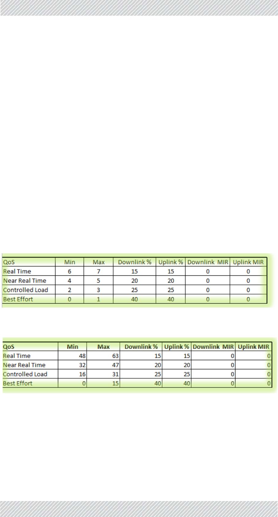
LowerTable:QualityofService(QoS)Options
ThelowertableoftheProjecttaballowsyoutosetQoSoptions.
ThelowertableoftheProjecttabisshowninFigure 3‐4(VLANcriteriashown):
Figure3‐4:Configurator‐Projecttab,lowertable
QoSOverview
Avarietyoftraffictypescontainingdifferentcontentcantravelthroughoutthenetwork,and
asaresultthroughRADWINequipment.Certaintypesaremoresensitivetodelaysthan
others,andassuchtheethernetnetworkplacesatagoneachpacketrepresentingitspriority.
TheRADWINQualityofServicefeature(QoS)canworkwithtwodifferentstandardsoftraffic
prioritization:VLAN(IEEE802.1q/p)andDiffserv(RFC2475).Eachofthesestandardsdivides
theprioritiesdifferently:VLANuses8levels,whileDiffservuses64levels.
RADWINequipmentcanrecognizethesenetworkprioritytags,andcanplacethetrafficin
oneof4differentQoSprioritylevels,asshowninTable 3‐1:
Product: N:Choosethisoptionifyouareusingthe802.11nradio
transmissionstandard.
AC:Choosethisoptionifyouareusingthe802.11acradio
transmissionstandard.
Table3‐1:DefaultprioritiesandallocationbyVLANvs.Diffserv
QoSPriorityLevel
StandardPriority
TypicalUse
DiffservVLAN
RealTime 48‐63 6‐7Highpriority:videoconferencing,phone
calls,etc.
NearRealTime 32‐47 4‐5
SlightlylowerprioritythanRealTime,but
withhigh‐qualitydeliverywithguaranteed
minimumlatency.Streamingvideo,internet
sites.
ControlledLoad 16‐31 2‐3
SimilartoBestEffortinuncongested
conditions.Averyhighpercentageof
transmittedpacketswillbedelivered
successfullyandnotexceedtheminimum
delay.Doesnotguaranteeminimumlatency.
BestEffort 0‐15 0‐1Lowestpriority:email,messaging,etc.
For Regualtor Approval Only
FinMDeploymentGuide Release4.2.46 3‐11
ProjectTab ConfiguringtheRadioNetwork
Thatis,ifworkingwiththeDiffservstandard,traffictaggedwithprioritylevelsfrom48to63
aretreatedas“RealTime”,thosewithlevelsfrom47to32aretreatedas“Nearrealtime”,etc.
TheRADWINQualityofServicefeature(QoS)allowsyoutochangewhichstandardpriority
levelistranslatedintoaprioritylevelusedinRADWINequipment.
Example:Ifyouknowyournetworkwillhaveagreatdealofhigherprioritytraffic,butyou
onlywantthehighesttoreceivepreferentialtreatment,youcandefine“RealTime”as
beingfrom55to63,insteadofthedefaultvalues48‐63.Youmustcoveralllevels,soin
thiscase,makesuretore‐define“NearRealTime”as32to54.
Percentages:Youcanseteachprioritylevel(intheuploadanddownloaddirectionseparately)
totakeupacertainpercentageofthetotaltraffic,solongasthatpercentageaddsupto100.
MIR:Youcanalsoplaceanabsolutemaximumlimitontheamountoftrafficallowedtopass
perprioritylevel,nomatterhowmuchtrafficcomesthrough.
SettingupQoS
QoSforTransportationFiberinMotionissetupintwophases:
1. ChoosetheQoSprioritystandard:Projecttab,uppertable,QoSMode
(ChooseNone,VLAN,orDiffserv)
Thelowertablewillshowthedefaultvaluesaccordingtothestandardyouhavechosen.
2. Configurethevaluesforeachqualitygroup:Projecttab,lowertable:
Figure3‐5:Configurator‐Projecttab,lowertable(VLANoptions)
Figure3‐6:Configurator‐Projecttab,lowertable(Diffservoptions)
Min:SettheminimumstandardprioritylevelthattheQoScategorywillreceive:
•InFigure 3‐5(showingvaluesaccordingtotheVLANstandard),RealTimehasa
minimumof6.
•InFigure 3‐6(showingvaluesaccordingtotheDiffservstandard),RealTimehasa
minimumof48.
For Regualtor Approval Only

FinMDeploymentGuide Release4.2.46 3‐12
LineTab ConfiguringtheRadioNetwork
Max:SetthemaximumstandardprioritylevelthattheQoScategorywillreceive.
•InFigure 3‐5(showingvaluesaccordingtotheVLANstandard),RealTimehasamaximumof7.
•InFigure 3‐6(showingvaluesaccordingtotheDiffservstandard),RealTimehasamaximumof63.
3. Downlink%andUplink%:SetthepercentageoftrafficeachQoScategoryistobeallotted.Thiscanbedifferentforthedownlink(TBS
‐>TMU)oruplink(TMU‐>TBS)direction.IftrafficofacertainQoSlevelismorethanthispercentage,itistreatedasBestEffort.
4. DownlinkMIRandUplinkMIR:Optional.IfyouwanttolimittrafficofacertainQoSleveltoacertainrate,enterthatratehere,in
Mbps(max:100).
3.4.3LineTab
TheLinetabisshowninFigure 3‐7:
Youmustmakesuretocoveralltheprioritylevels,otherwisethesystemwill
createerrors.Nowarningwillbegiven.
Thepercentagescannotadduptomorethan100,otherwisethesystemwill
createerrors.Nowarningwillbegiven.
Ifthepercentagesadduptolessthan100,theunusedprioritywillbedistributed
totheremainingpriorities.
For Regualtor Approval Only

FinMDeploymentGuide Release4.2.46 3‐13
LineTab ConfiguringtheRadioNetwork
Figure3‐7:Configurator‐Linetab
EnterthevariousIPaddressesforthedevicesshown.
ThedevicesonthefirstlineoftheworksheetareassociatedwithLine1,thoseonthesecond
linewithLine2,etc.
No. Enterthelinenumber.
HMUGateway: TMUgatewayforallTMUsontheline.TheindividualIP
addressesoftheTMUsontherailcarsaredefinedintheTrain
tab(seeTrainTabonpage 3‐17).
HMUSubnet: TMUsubnetforallTMUsontheline.
HBSGateway: TBSgatewayforallTBSsontheline.TheindividualIPaddresses
oftheTBSsaredefinedintheTowerstab(seeTowersTabon
page 3‐15).
HBSSubnet: TBSsubnetforallTBSsontheline.
HMUManagement
VLAN:
VLANdefinitionforallTMUs.
HBSManagement
VLAN:
VLANdefinitionforallTBSs.
SynchronizationVLAN: VLANdefinitionforallISUs.
Synchronization
DomainID:
DomainIDforallISUs.
L2LearningVLAN: VLANdefinitionforthedata(traffic)stream.Called“learning”
becauseitrelatestothefactthateachTBSmustlearnaboutthe
newTMUthatiscomingintoitsrange.
ISUIP: IPaddressfortheprimaryISUintheline
BackupISUIP: IIPaddressofthesecondaryISUintheline
Line: Thenameoftheline.Thisnamewillbeusedinseveralplaces,
sousealogicalterm.
For Regualtor Approval Only

FinMDeploymentGuide Release4.2.46 3‐14
LineTab ConfiguringtheRadioNetwork
Color: Eachlinehasaseparatecolor,helpingyoutokeepthings
organized.Setthebackgroundcolorforthelinehere.Thecolor
isshown,andisalsousedasabackgroundfortheConfigure
Unitdialogbox(seeConfiguringNetworkUnitsonpage 3‐25),in
theTowerstab(seeTowersTabonpage 3‐15),andtheTraintab
(seeTrainTabonpage 3‐17).
ThefirsttwodigitsarefortheRedcolorcomponent(Hexformat
from00forblacktoFFforRed),thenexttwoarefortheGreen
colorcomponent(Hexformatfrom00forblacktoFFforGreen),
andthelasttwoarefortheBluecolorcomponent(Hexformat
from00forblacktoFFforBlue).
AdditionalLearning
VLANs
Notforcustomeruse
Table3‐2:ColorCodes
Value Color
#FF0000 Red
#00FF00 Green
#0000FF Blue
#FF00FF Magenta
#00FFFF Cyan
#FFFF00 Yellow
For Regualtor Approval Only
FinMDeploymentGuide Release4.2.46 3‐15
TowersTab ConfiguringtheRadioNetwork
3.4.4TowersTab
TheTowerstabisshowninFigure 3‐8:
Figure3‐8:Configurator‐Towerstab
UsetheTowerstabtodefinetheconnectivitycharacteristicsofallTBSsintheproject.
InsomeversionsoftheConfigurationfile,someofthefieldsarelinkedtoothers.Thisisproject‐specificandmaynotberelevantforyourproject.
Youmustverifythatallvaluesenteredarethecorrectones.
HBSNTPServer: IPaddressoftheNetworkTimingProtocolserverforallTBSsin
thenetwork.
HMUNTPServer: IPaddressoftheNetworkTimingProtocolserverforallTMUsin
thenetwork.
No. SequencenumberoftheTBSinthewholeproject.
Name EnteranamefortheTBS.Choosealogicalname,asthisnameis
usedinmanyplaces.
For Regualtor Approval Only

FinMDeploymentGuide Release4.2.46 3‐16
TowersTab ConfiguringtheRadioNetwork
ACC‐BS IPaddressoftheTBSunit.
Frequency Fromthepull‐downmenu,choosethefrequencyatwhichthe
TBSunitwillwork.
ThefrequenciesaredeterminedbyBand:andChannel
Bandwidth:valuesintheTowertab.F1,F2,F3,etcwillbethe
basefrequencychoseninBand,withthevaluechosenin
ChannelBandwidthadded.
Forexample,iftheBandchosenis5.475‐5.720GHz,andthe
bandwidthis40MHz,thenF1=5.475GHz,F2=5.515GHz,F3=
5.555GHz,etc.
kHz ThefrequencyinkHzisshownautomaticallyasaresultofyour
choiceintheFrequencycolumn.
FrequencyNeighbors ShowsthefrequenciesoftheneighborsoftheTBS.Thevalues
showndependonthenamesoftheneighborsyouenterinthe
BaseNeighborscolumn.
Line Choosethenumberofthelinehere,precededbyazero.
Dir Write1ifthereisoneTBSthatservesbothdirections,write2of
thereisaTBSforeachdirection.
No.SequencenumberoftheTBSinthespecificline.
BaseNeighbors Enterthename(s)ofeachTBSthatiscloseenoughtobe
consideredaneighbor.Becarefultoentertheexactsameterm
fortheneighboringTBSasshownintheNamecolumnforthat
unit.Separatemultiplevaluesbyacomma.
IPNeighborsList ShowstheIPaddressesoftheneighboringTBSunitsin
accordancewiththelistyoucreatedintheBaseNeighbors
column.
NeighborLineNo. Shows,inorder,thelinenumberforeachneighboringTBSunit,
naccordancewiththelistyoucreatedintheBaseNeighbors
column.
Co‐ChannelNeighbor UsedforInterferenceMitigationforCo‐channelNeighbors.(see
InterferenceMitigationforCo‐channelNeighborsonpage 3‐18).
Ifyourprojectuses3orfewerfrequencies,thenwerecommend
youusethisoption.
Enterthename(s)oftheco‐channelneighbor(s).Ifthereare
morethanone,separatethembyacomma(nospaces!).
Co‐ChannelNeighbor‐
sIPs
ShowstheIPaddress(es)oftheco‐channelneighbor(s)in
accordancewiththenamesyourecordedintheCo‐Channel
Neighborcolumn.UsedforInterferenceMitigationforCo‐
channelNeighbors.
For Regualtor Approval Only

FinMDeploymentGuide Release4.2.46 3‐17
TrainTab ConfiguringtheRadioNetwork
3.4.5TrainTab
TheTraintabisshowninFigure 3‐9:
Figure3‐9:Configurator‐Traintab
CNIndex IndicateswhichTBSwillusewhichtimeslotsintheframe,inthe
InterferenceMitigationforCo‐ChannelNeighborsoption.
No. SequencenumberoftheTMUinthewholeproject.
IP IPaddressoftheTMU.
Line LineonwhichtheTMUworks.
Num WhentwoTMUsareusedonacar,setherewhichTMUis“1”
andwhichoneis“2”.Thisisnotnecessarilythe“active”or
“passive”TMU;thatisdeterminedbyconditionsinthefieldand
canchangefromminutetominute.
Car#1 NameofCar#1.Choosealogicalname,asthisnameisusedin
manyplaces.
(Car#2) (Optional)NameofCar#2.Choosealogicalname,asthisname
isusedinmanyplaces.
Car#1RouterIP IPaddressofrouterinCar#1.
NotethatthisistheIPaddressoftherouter,andnotofthe
TMU,oranyotherindividualpieceofequipmentonboard.This
keepsthenetworksimple‐astheTBS,ISUs,andotheritems
relatetothissingleIPaddress,andnottothemanyIPaddresses
oftheindividualitemsofequipment.
For Regualtor Approval Only
FinMDeploymentGuide Release4.2.46 3‐18
InterferenceMitigationforCo‐channelNeighbors ConfiguringtheRadioNetwork
3.5InterferenceMitigationforCo‐channel
Neighbors
Ifyoursystemuses3orfewerfrequencies,werecommendthatyouusetheCo‐Channel
NeighborInterferenceMitigationmethoddescribedheretoreduceinterferencebetween
TBSs.
•ThismethodisusedinadditiontotheHubSiteSynchronizationmethod.
•Ifyoursystemusesmorethan3frequencies,thismethodofinterferencemitigationis
notneeded.
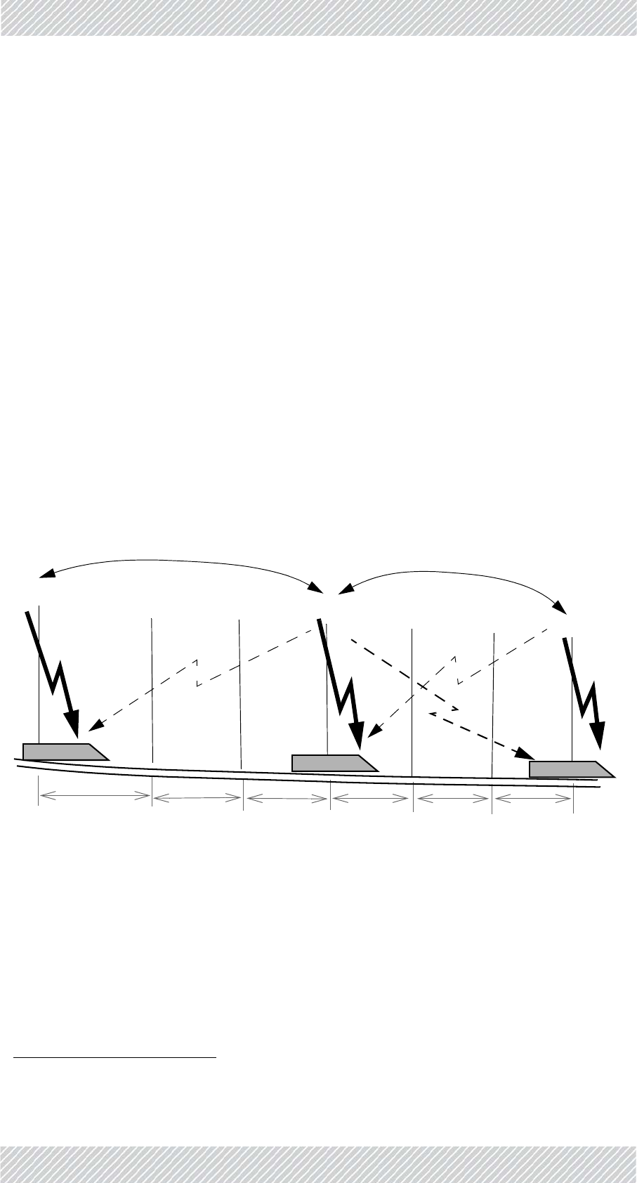
3.5.1BasicSituation
ThethreefrequenciesareusedontheTBSsinastaggeredfashion:TBS1usesF1,TBS2uses
F2,TBS3usesF3.Thepatternisthenrepeated:TBS4hasagainF1,TBS5hasF2,TBS6hasF3,
andsoon.
WeassumethatthenominaldistancebetweeneachTBSisatleast500m(belowground;
abovegroundthisvaluecanbeaslargeas2000m).SeeFigure 3‐10.
Figure3‐10:Co‐ChannelNeighbors
Atagivenmoment,arailcar(withTMU1)issynchronizedwithTBS1,andusingfrequencyF1.
Atthissamemoment,thisrailcarisabout1500metersawayfromTBS4,whichisalsousing
F11.
AnysignalthatTMU1receivesfromTBS4atthispointisconsideredinterference.Ifthesignal
fromTBS4isstrongenough,theinterferencecanharmthethroughput,andneedstobe
mitigated.
1. Iffewerthan3frequenciesareused,thevalueswouldbe1000mfortwoand500mforonefrequency.
TBS1 TBS4 TBS7
TBS2 TBS3 TBS5 TBS6
TMU1 TMU4 TMU7
500m 500m 500m 500m 500m 500m
co‐channelneighbors co‐channelneighbors
For Regualtor Approval Only

FinMDeploymentGuide Release4.2.46 3‐19
NecessaryPre‐Conditions ConfiguringtheRadioNetwork
Thissituationcontinuesthroughouttheline‐TBS7caninterferewithTBS4/TMU4,andinturn
TBS4caninterferewithTBS7/TMU7.TBS7canfurtherinterferewithTBS10,TBS10can
interferewithTBS7andTBS13,andsoondowntheline.
Thetwounitsthatcaninterferewitheachotherarecalled“co‐channelneighbors”.
3.5.2NecessaryPre‐Conditions
Ifthe“Co‐ChannelNeighborInterferenceMitigation”optionisconfigured,itwillbeactivated
orde‐activatedautomaticallyaccordingtotheconditionsdescribedbelow.Notethatthe
activationconditionsandde‐activationconditionsarenotexactlysymmetrical.
ActivationConditions
»TheTBSco‐channelneighboristransmittingwiththePrimaryTMUonitsrailcar1,
AND
»ThedetectedsignalfromtheTBSco‐channelneighborisabovethethresholdsignal
strengthforactivation(seeTable 3‐3).
De‐ActivationConditions
»TheTMUoftheTBSco‐channelneighborisre‐definedastheSecondaryTMU,
OR
1. Thisisthe“active”TMU.Iftheco‐channelneighboristransmittingwithitsSecondaryTMU,thesignalwillbe
weakerandsporadic,resultinginalowenoughinterferencelevelastobeinsignificant.
Table3‐3:Thresholdsignalstrengthlevels‐activationcriteria
SignalStrengthbetween
TBSandTMU
Differenceinsignal
strengthbetweenTBS
anditsco‐channel
neighbor
ActivateOption?
‐70orabove Greaterthan16 No
‐70orabove 16orless Yes
‐74to‐71 Greaterthan14 No
‐74to‐71 14orless Yes
‐78to‐75 Greaterthan12 No
‐78to‐75 12orless Yes
‐79orbelow Greaterthan9No
‐79orbelow 9orless Yes
For Regualtor Approval Only

FinMDeploymentGuide Release4.2.46 3‐20
MethodofOperation ConfiguringtheRadioNetwork
»ThedetectedsignalfromtheTBSco‐channelneighborisbelowthethresholdsignal
strengthforde‐activation(thevaluesaredifferentfromthatofactivation:seeTable 3‐
4).
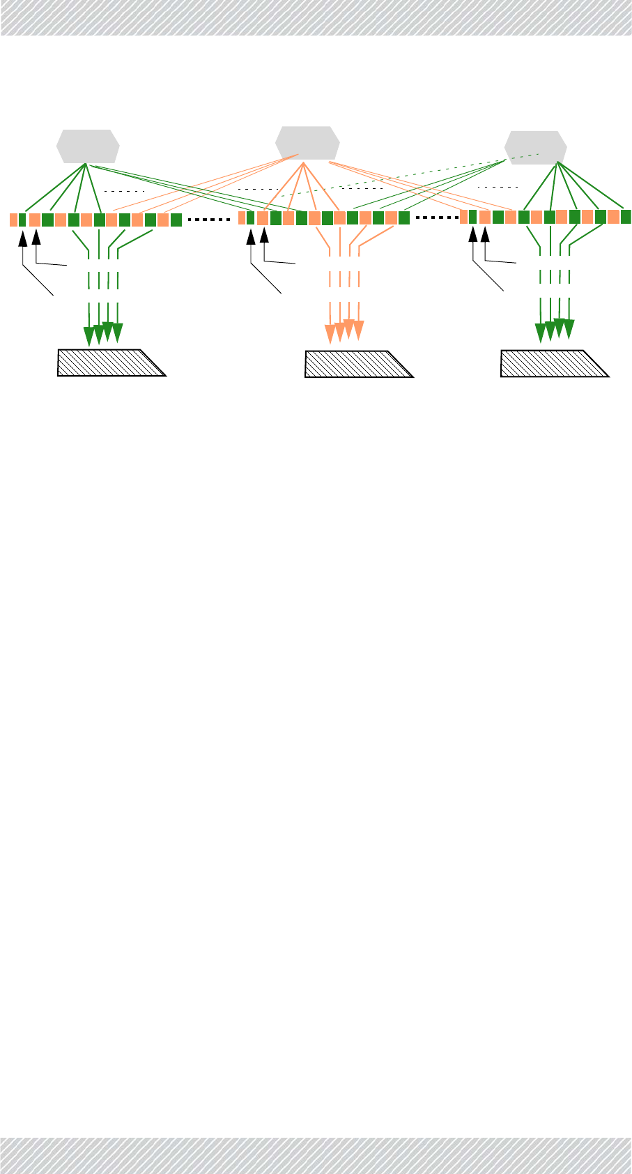
3.5.3MethodofOperation
Theco‐channelneighborinterferencemitigationoptionworksasfollows:
Splittimeslots:TBS1isconfiguredtosplitthetimeslotsintheframebetweenitandbetween
its“co‐channelneighbor”(inourcase,withthreefrequencies,it’swithTBS4)1.The
resultforthefirstco‐channelneighborpairisthatTBS1transmitsonhalfofthetime
slots,andTBS4transmitsontheotherhalf.SeeFigure 3‐11.
TMU1isinstructedtoreceivethosetimeslotsthatwereassignedtoTBS1,andignore
others.
Noticethatinourexample,TBS1andTBS7areassignedthesametimeslots.Thisis
notaproblembecauseTBS1andTBS7aresofarawayfromeachotherthattheir
mutualsignalsdonotinterfere.
Repeatforallco‐channelneighbors:ThisconfigurationisepeatedwithTBS2vs.TBS5,again
withTBS3vs.TBS6,andevenwithTBS7vs.TBS4,andsoondowntheline.
Table3‐4:Thresholdsignalstrengthlevels‐de‐activationcriteria
SignalStrengthbetween
TBSandTMU
Differenceinsignal
strengthbetweenTBS
anditsco‐channel
neighbor
De‐Activate
Option?
‐70orabove Greaterthan20 Yes
‐70orabove 20orless No
‐74to‐71 Greaterthan18 Yes
‐74to‐71 18orless No
‐78to‐75 Greaterthan16 Yes
‐78to‐75 16orless No
‐79orbelow Greaterthan13 Yes
‐79orbelow 13orless No
1. WhichTBSreceiveswhichtimeslotsisdeterminedbytheCNIndexparameter(seepage 3‐24)
For Regualtor Approval Only
FinMDeploymentGuide Release4.2.46 3‐21
ConfiguringtheCo‐ChannelNeighborInterferenceMitigationOption ConfiguringtheRadioNetwork
Figure3‐11:Dividingtimeslotsbetweenco‐channelneighbors
Thissplittingoftimeslotsisenabledonlyiftheactivationconditionsdescribedabove(see
ActivationConditions)aremet.
Thingscanchangerapidly,soatthemomentthede‐activationconditionsaremet(seeDe‐
ActivationConditions),thedivisionoftimeslotsisnolongercarriedout.
Whentheconditionsreturntotheactivationconditions,thedivisionoftimeslotsisrenewed.
3.5.4ConfiguringtheCo‐ChannelNeighborInterference
MitigationOption
ConfigureeachTBSfor“Co‐ChannelNeighborInterferenceMitigation”asfollows:
5. OpentheConfigurator.
6. SelecttheMaintab
7. ClickUnprotect.
8. EnterthepasswordandclickOK.
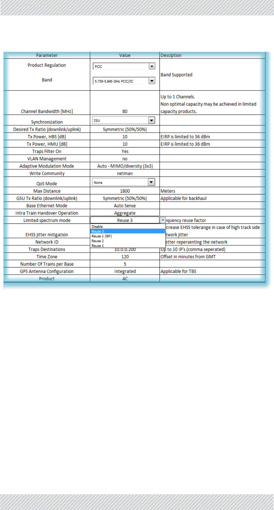
9. SelecttheProjecttab(seeFigure 3‐12):
TBS1 TBS4 TBS7
TMU1 TMU4 TMU7
ReceivesTBS1timeslotsonly
TimeslotassignedtoTBS4
TimeslotassignedtoTBS1
ReceivesTBS4timeslotsonly
TimeslotassignedtoTBS4
TimeslotassignedtoTBS1andTBS7
ReceivesTBS7timeslotsonly
TimeslotassignedtoTBS4
TimeslotassignedtoTBS7
For Regualtor Approval Only
FinMDeploymentGuide Release4.2.46 3‐22
ConfiguringtheCo‐ChannelNeighborInterferenceMitigationOption ConfiguringtheRadioNetwork
Figure3‐12:ProjectTab:LimitedSpectrumMode
10.SelecttheLimitedSpectrumModeoption
11.ChooseReuse3fromthepull‐downmenu.Thiswillinstructthesystemthatyou
areusing3frequencies.Ifyouareusing2frequencies,chooseReuse2,ifyouare
using1frequency,chooseReuse1.
For Regualtor Approval Only

FinMDeploymentGuide Release4.2.46 3‐23
ConfiguringtheCo‐ChannelNeighborInterferenceMitigationOption ConfiguringtheRadioNetwork
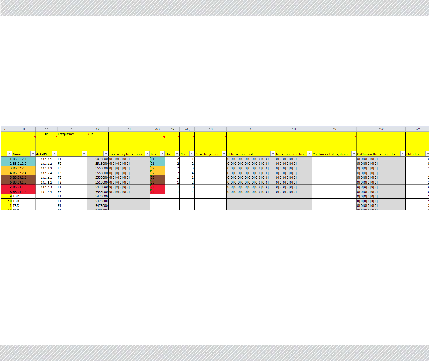
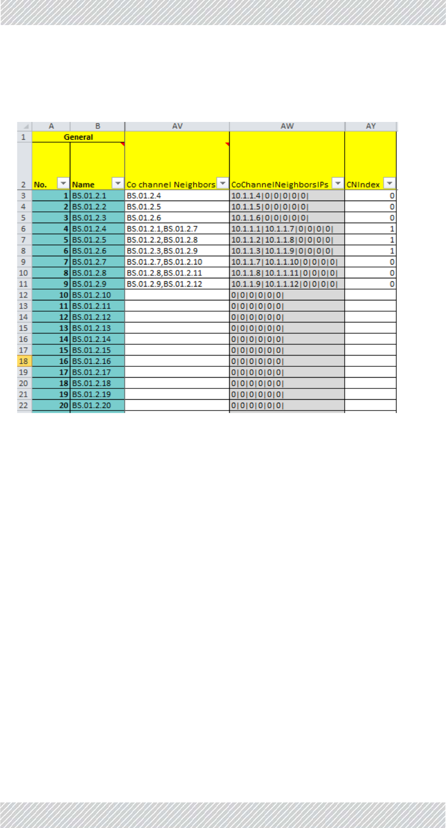
12.ClicktheTowerstab:
Figure3‐13:TowersTaboftheConfigurator
•ColumnAshowsthenumberofeachTBS.
•ColumnBshowsthe“name”(orserialnumber)ofeachTBS.
•ColumnAAshowstheIPaddressofeachTBS.
•ColumnAJindicateswhichfrequency(F1,F2,orF3inourexample)isbeingused
forthespecificTBS.
•ColumnAKshowsthevalueofthefrequencyinkHz.
•ColumnAVshowsthename(s)oftheco‐channelneighbor(s).
•ColumnAWshowstheIPaddress(es)oftheco‐channelneighbor(s).
•ColumnAYshowsthe“CNIndex”(whichtimeslottheindicatedTBSistouse).
Wecanseethatinourexample,wearere‐usingF1throughF3
(columnsoftheExcelsheetnotneededhavebeencollapsedforclarity).
13.Recordtheco‐channelneighbor(s)ofeachTBSasfollows:
For Regualtor Approval Only
FinMDeploymentGuide Release4.2.46 3‐24
ConfiguringtheCo‐ChannelNeighborInterferenceMitigationOption ConfiguringtheRadioNetwork
IncolumnAV(Co‐channelNeighbors),recordthenameoftheco‐channelneighborTBS(s).
Iftherearetwoco‐channelneighbors,recordeachneighbor’snameseparatedbya
comma(nospaces!),asshowninFigure 3‐14:
Figure3‐14:RecordingCo‐ChannelNeighbors
TheIPaddress(es)oftheco‐channelneighbor(s)appearautomaticallyincolumnAW.
Inourexample,theco‐channelneighborofTBS1(BS.01.2.1)isBS.01.2.4,thatofTBS2
(BS.01.2.2)isBS.01.2.5,andofTBS3(BS.01.2.3)isBS.01.2.6.
StartingfromTBS4,eachTBShastwoco‐channelneighbors:theneighborsofTBS4
(BS.01.2.4)areTBS1(BS.01.2.1)andTBS7(BS.01.2.7),andsoon.
Thispatternwillrepeatitselfuntiltheendoftheline.ThelastthreeTBSsattheendofthe
line,likethefirstthree,willhaveonlyoneco‐channelneighbor.
14.Completerecordingalloftheco‐channelneighborsforallTBSsinthespecificline
(wehaveonlyrecordeduptoTBS9inourexample).
15.IncolumnAY,recordtheCNIndex:ThisindicateswhichTBSwillusewhich
timeslotsintheframe‐thefirstpartorthesecondpart(seealsoFigure 3‐11).
Record0fortheTBSsthatwillusethefirstpart,and1fortheTBSthatwillusethe
secondpart.
Inourexample,TBS1,2,and3usethefirstpartofthetimeslotsintheframe(0is
recorded),whileTBS4,5,and6usethesecondpartofthetimeslots.ForTBS7,8,and9,
theyagainusethefirstpartofthetimeslots(so,forinstanceTBS4alwaysusesadifferent
partoftheframethanitsco‐channelneighbor:CNIndex1vs.CNIndex0forTBS1andfor
TBS7).Thepatternrepeatsitselfuntiltheendoftheline.
For Regualtor Approval Only

FinMDeploymentGuide Release4.2.46 3‐25
ConfiguringNetworkUnits ConfiguringtheRadioNetwork
16.Onceyouhaveenteredallthenecessaryinformation,selecttheMaintab.
17.ClickRecalcalldatatoupdatethesystemwiththechangesyouhavemade,and
savethefile.
3.6ConfiguringNetworkUnits
ConfiguringanIndividualUnit:
Toconfigureindividualnetworkunitsoneatatime(TBS,TMU,andISUscanbeconfig‐
ured),clickConfigureUnitontheMaintaboftheConfigurator.ThisopenstheConfigura‐
tordialogbox.Seesectionssee3.6.1onpage 3‐25throughsee3.6.3onpagepage 3‐29
fordetailsonworkingwiththeConfiguratordialogbox.
ConfiguringManyUnitsatOnce:
YoucanconfigurealltheTBSunitsintheline,asdeterminedbythevalueintheLinewin‐
dow.DothisbyclickingtheHBSBatchConfigurationbutton.Thiswilltakeallofthe
parametervaluesthatareinthisfileforthespecificline,andapplythemtoalloftheTBS
unitsdefinedintheline.ConnectioniscarriedoutaccordingtotheIPaddressesasappear
inthisfile.
3.6.1ConfiguringTransportationBaseStations(TBSs)
UsethisproceduretocarryoutchangesintheconfigurationparametersoftheTBSs.This
includeschangingorsettingitsIPaddress.
1.Forafirst‐timeconfiguration,connecttheTBS’sPoEsockettoaPoEdevice(seeSite
Installationforconnectioninstructions),andinturn,connectthePoEdevicetoyour
laptoporaLANconnection.
Forare‐configurationofaTBSalreadyinstalledinthefield,youcanrelyonyournet‐
work’sconnection.
2. OpentheConfigurator.
3. FromtheMaintab,clicktheLinepull‐downmenuandselectthelineonwhichthe
TBSisdefined(seeFigure 3‐2).
4. FromtheDownloadSoftwarepull‐downmenu,selecttheappropriate
configurationoption(seepage 3‐4foradescriptionoftheseoptions).
5. ClickConfigureUnit.Thefollowingwindowwillappear:
Configureallnetworkunitsbeforeyouinstalltheminthefield.
For Regualtor Approval Only

FinMDeploymentGuide Release4.2.46 3‐26
ConfiguringTransportationBaseStations(TBSs) ConfiguringtheRadioNetwork
Figure3‐15:TBS‐FirsttimeInstallation
6. Type:Selecttheradiotype‐chooseAccessRadio,asshowninFigure 3‐15.
7. BaseName:SelectthenameoftheTBSfromadrop‐downmenulist.Thelistof
thesenamesaretakenfromthosedefinedintheTowerstab,andcomefromthe
selectedlineonly.ItsIPaddresswillthenappearnexttotheFirstInstallation
windowifthereisnocheckmarknexttoit.
8. Role:LeavethissettingasPrimary.
9. FirstInstallation:Forafirst‐timeinstallation,leavethisoptionselectedsothe
defaultIPaddresswillappear.Anyactionstakenwillthenaffectthisunit,notthe
unitselectedfromtheBaseNamedrop‐downmenulist.
10. ClickOK.TheConfiguratorwilltakeallparametersasshownintheConfiguratorthat
arerelevantfortheselectedTBSandcarryouttheactionasdeterminedbythe
DownloadSoftwareoptionyouhaveselected(seeDownloadsoftware:onpage 3‐
4).
Itmaytakeaboutaminutetocomplete.Youwillreceiveoneofthecompletionmes‐
sagesdescribedinConfiguratorMessagesbelow.
Tore‐configureaunitthatisalreadyinstalled:
1.RepeatStepssee1.throughsee8.above,relyingonyournetwork’sconnectionto
theunit.
2. RemovethecheckmarkfromFirstInstallation,andentertheIPaddressoftheunit
youwishtore‐configure:
Thebackgroundcolorofthedeviceconfigurationwindowisthesamecoloras
thatdefinedinLinetab,Namecolumn.
For Regualtor Approval Only
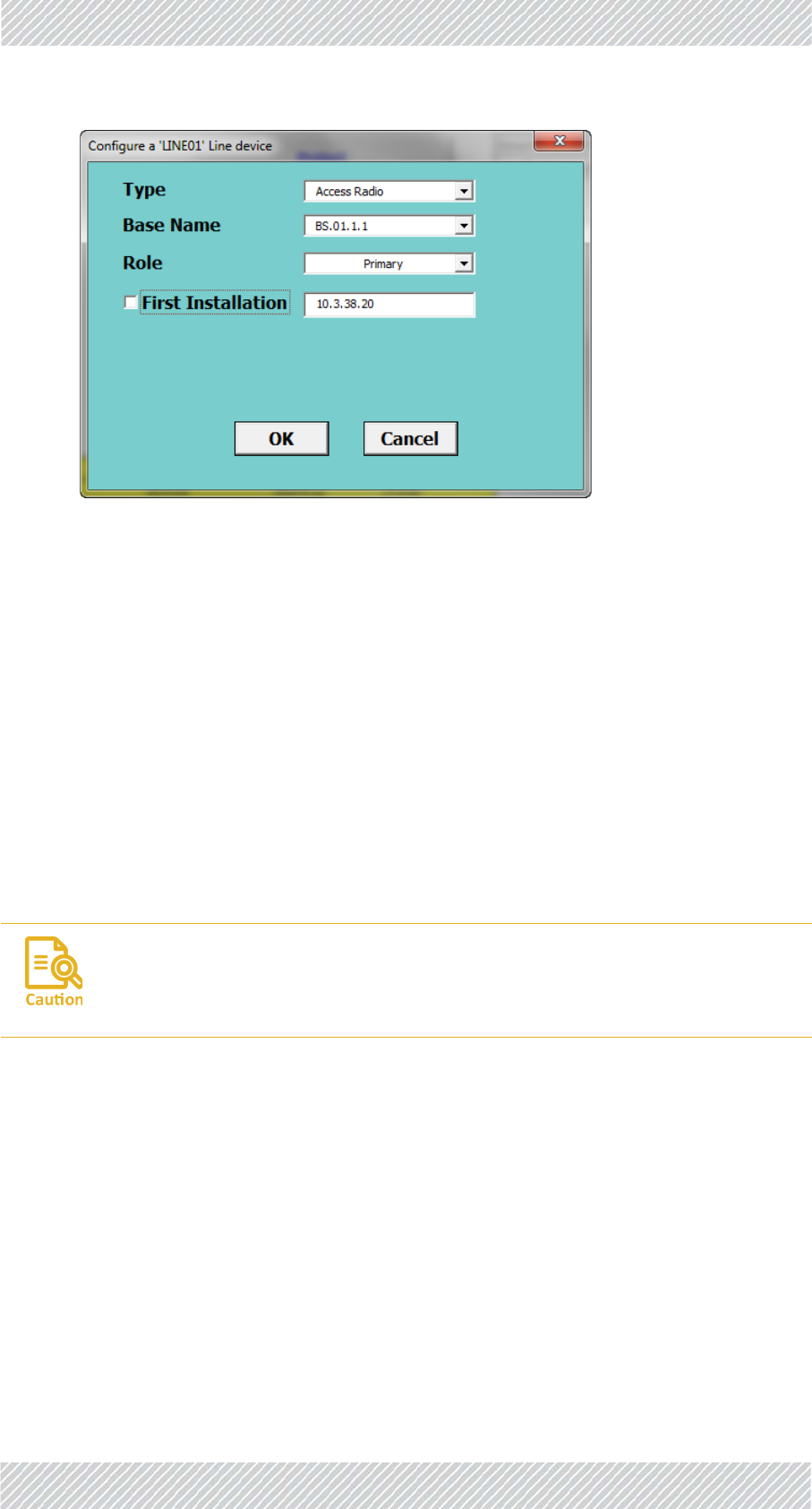
FinMDeploymentGuide Release4.2.46 3‐27
ConfiguringTransportationMobileUnits(TMUs) ConfiguringtheRadioNetwork
Figure3‐16:TBS‐Re‐configuration
3. ClickOK.TheConfiguratorwilltakeallparametersasshownintheConfiguratorthat
arerelevantforaTBSandcarryouttheactionasdeterminedbytheDownload
softwareoptionyouhaveselected(seeDownloadsoftware:onpage 3‐4).Ifthe
actionincludesdownloadingtoaunit,itwilldownloadtotheunitwhoseIPaddress
appearsintheFirstInstallationwindow,regardlessofwhichunitappearsinthe
BaseNamewindow.
Itmaytakeaboutaminutetocomplete.Youwillreceiveoneofthecompletionmes‐
sagesdescribedinConfiguratorMessagesbelow.
3.6.2ConfiguringTransportationMobileUnits(TMUs)
UsethisproceduretocarryoutchangesintheconfigurationparametersoftheTMUs.This
includeschangingorsettingitsIPaddress.
1.Forafirst‐timeconfiguration,connecttheTMU’sPoEsockettoaPoEdevice(see
SiteInstallationforconnectioninstructions),andinturn,connectthePoEdeviceto
yourlaptoporaLANconnection.
Forare‐configurationofaTMUalreadyinstalledinthefield,youcanrelyonyour
network’sconnection.
2. OpentheConfigurator.
3. FromtheMaintab,clicktheLinepull‐downmenuandselectthelineonwhichthe
TMUisdefined(seeFigure 3‐2).
4. FromtheDownloadSoftwarepull‐downmenu,selecttheappropriate
configurationoption(seepage 3‐4foradescriptionoftheseoptions).
SinceTMUsareusuallymobile,makesurethesedeviceswillbeincontinuous
contactduringtheconfigurationprocess.Ourrecommended“bestpractice”isto
findanopportunitywhentheTMUtobeconfiguredisimmobile.
For Regualtor Approval Only

FinMDeploymentGuide Release4.2.46 3‐28
ConfiguringTransportationMobileUnits(TMUs) ConfiguringtheRadioNetwork
5. ClickConfigureUnit.Thefollowingwindowwillappear:
Figure3‐17:TMU‐FirsttimeInstallation
6. Type:Selecttheradiotype‐TrainRadio,asshowninFigure 3‐17.
7. Car:Selectthenameofthetraincaronwhichtheunitistobeinstalled.Alistof
thesenamesaretakenfromthosedefinedintheTrainstab,Carcolumn,andcome
fromtheselectedlineonly.ItsIPaddresswillthenappearnexttotheFirst
Installationwindowifthereisnocheckmarknexttoit.
8. CarRouter:ThisshowstheIPaddressoftherouterontheselectedtraincar.thisIP
addressisdefinedintheTrainstab,CarRouterIPcolumn.
9. FirstInstallation:Forafirst‐timeinstallation,leavethisoptionselectedsothe
defaultIPaddresswillappear.Anyactionstakenwillthenaffectthisunitdirectly,
nottheunitselectedfromtheCardrop‐downmenulist,norwillitusetheCar
Router.
10. ClickOK.TheConfiguratorwilltakeallparametersasshownintheConfiguratorthat
arerelevantfortheselectedTMUandcarryouttheactionasdeterminedbythe
DownloadSoftwareoptionyouhaveselected(seeDownloadsoftware:onpage 3‐
4).
Itmaytakeaboutaminutetocomplete.Youwillreceiveoneofthecompletionmes‐
sagesdescribedinConfiguratorMessagesbelow.
Tore‐configureaunitthatisalreadyinstalledinthefield:
1.RepeatStepssee1.throughsee8.above,relyingonyournetwork’sconnectionto
theunit.
Thebackgroundcolorofthedeviceconfigurationwindowisthesamecoloras
thatdefinedinLinetab,Namecolumn.
For Regualtor Approval Only

FinMDeploymentGuide Release4.2.46 3‐29
ConfiguringIndoorSynchronizationUnits(ISUs) ConfiguringtheRadioNetwork
2. RemovethecheckmarkfromFirstInstallation,andentertheIPaddressoftheunit
youwishtore‐configure.NotethatthecorrectIPaddressoftheCarRouterwill
appear.
Figure3‐18:TMU‐Re‐configuration
3. ClickOK.TheConfiguratorwilltakeallparametersasshownintheConfiguratorthat
arerelevantforaTMUandcarryouttheactionasdeterminedbytheDownload
softwareoptionyouhaveselected(seeDownloadsoftware:onpage 3‐4).Ifthe
actionincludesdownloadingtoaunit,itwilldownload,viatheCarRouterwhoseIP
addressisshown,totheunitwhoseIPaddressappearsintheFirstInstallation
window,regardlessofwhichunitappearsintheCarwindow.
Itmaytakeaboutaminutetocomplete.Youwillreceiveoneofthecompletionmes‐
sagesdescribedinConfiguratorMessagesbelow.
3.6.3ConfiguringIndoorSynchronizationUnits(ISUs)
UsethisproceduretocarryoutchangesintheconfigurationparametersoftheISUs.This
includeschangingorsettingitsIPaddress.
1.Forafirst‐timeconfiguration,connecttheISU’ssyncsockettoyourlaptoportoa
LANconnection.ConnectACpowertoitspowerinput.SeeSiteInstallationforcon‐
nectioninstructions.
Forare‐configurationofanISUalreadyinstalledinthefield,youcanrelyonyour
network’sconnection.
2. OpentheConfigurator.
3. FromtheMaintab,clicktheLinepull‐downmenuandselectthelineonwhichthe
ISUisdefined(seeFigure 3‐2).
4. FromtheDownloadSoftwarepull‐downmenu,selecttheappropriate
configurationoption(seepage 3‐4foradescriptionoftheseoptions).
5. ClickConfigureUnit.Thefollowingwindowwillappear:
For Regualtor Approval Only

FinMDeploymentGuide Release4.2.46 3‐30
ConfiguringIndoorSynchronizationUnits(ISUs) ConfiguringtheRadioNetwork
Figure3‐19:ISU‐Firsttimeinstallation
6. Type:Selecttheunittype‐LinesyncUnit(ISU),asshowninFigure 3‐19.
7. UnitName:SelectthenameoftheISUassociatedwiththisline.Thisnameconsists
ofISU.LineNumber.ThenameistakenfromthosedefinedintheLinetab.ItsIP
addresswillthenappearnexttotheFirstInstallationwindowifthereisno
checkmarknexttoit.
8. Role:SelecttheroleoftheISU.ThisiseitherPrimaryorSecondary.SeetheLine
tab:ISUIP,andBackupISUIPfordefinitionsoftheirIPaddresses.
9. FirstInstallation:Forafirst‐timeinstallation,leavethisoptionselectedsothe
defaultIPaddresswillappear.Anyactionstakenwillthenaffectthisunit,notthe
unitshownintheUnitNamewindow.
10. ClickOK.TheConfiguratorwilltakeallparametersasshownintheConfiguratorthat
arerelevantfortheISUshownandcarryouttheactionasdeterminedbythe
DownloadSoftwareoptionyouhaveselected(seeDownloadsoftware:onpage 3‐
4).
Itmaytakeaboutaminutetocomplete.Youwillreceiveoneofthecompletionmes‐
sagesdescribedinConfiguratorMessagesbelow.
Tore‐configureaunitthatisalreadyinstalledinthefield:
1.RepeatStepssee1.throughsee8.above,relyingonyournetwork’sconnectionto
theunit.
2. RemovethecheckmarkfromFirstInstallation,andentertheIPaddressoftheunit
youwishtore‐configure.
Thebackgroundcolorofthedeviceconfigurationwindowisthesamecoloras
thatdefinedinLinetab,Namecolumn.
For Regualtor Approval Only
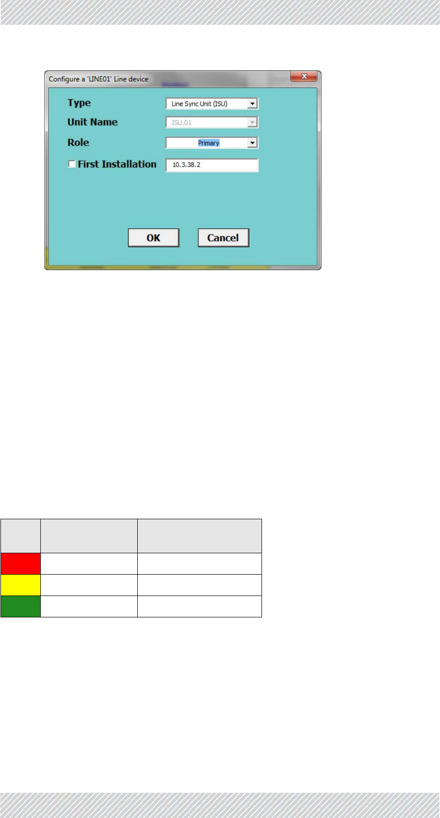
FinMDeploymentGuide Release4.2.46 3‐31
ConfiguratorMessages ConfiguringtheRadioNetwork
Figure3‐20:ISU‐Re‐configuration
3. ClickOK.TheConfiguratorwilltakeallparametersasshownintheConfiguratorthat
arerelevantforanISUandcarryouttheactionasdeterminedbytheDownload
softwareoptionyouhaveselected(seeDownloadsoftware:onpage 3‐4).Ifthe
actionincludesdownloadingtoaunit,itwilldownloadtotheunitwhoseIPaddress
appearsintheFirstInstallationwindow,regardlessofwhichunitappearsinthe
UnitNamewindow.
Itmaytakeaboutaminutetocomplete.Youwillreceiveoneofthecompletionmes‐
sagesdescribedinConfiguratorMessagesbelow.
3.7ConfiguratorMessages
Table3‐5:ConfiguratorMessageColorCodes
Color
Code Meaning ActionRequired
Red Operationfailed Varieswithmessage
Yellow OK Repeattheoperation
Green OK Operationsuccessful
For Regualtor Approval Only

FinMDeploymentGuide Release4.2.46 3‐32
ConfiguratorMessages ConfiguringtheRadioNetwork
Ifyouareaskedtorestartthedevice,logintoitwithtelnetfollowingthisexample:
Figure3‐21:LoggingintoanTBSwithTelnet
Theusernameandpasswordarerespectively,adminandnetman.
Table3‐6:ConfiguratorMessages
Color
Code Message ActionRequired
Can'tfindConfiguration
ContactsupplierCan'tlogintodevice.Checkpassword
Failedtogetdeviceconfiguration
NoconnectionwithDevice
Ping,thencheckphysical
connection.Ifallfails,replacethe
device.
PermissionError Contactsupplier
ScriptError
TelnetConnectiontothedevicefailed
Ping,thencheckphysical
connection.Ifallfails,replacethe
device.
WrongProductConnected Checkformix‐up‐TMUforTBSor
viceversa
Pleaserunagaintocomplete.
Repeatthisconfiguration‐this
mayoccurduringasoftware
upgrade.
Configurationcompleted‐Devicerestarting... None
Configurationcompleted‐Pleaserestartdevice. LoginwithTelnetandusethe
rebootcommand(Seebelow)
For Regualtor Approval Only

FinMDeploymentGuide Release4.2.46 3‐33
ConfiguratorMessages ConfiguringtheRadioNetwork
Figure3‐22:UsingtheTelnetrebootcommandtoresetanTBS
Hereisanexample:
Table3‐7:RadioInventory
ABCMetroRadioInventory
RadioType Active Backup Total
BaseRadios 158 0 158
TrainRadios 298 0 298
SyncUnit(ISU) 448
Table3‐8:DistributionofRadioInventoryacrosslines
Line Name Base Train
5Line01 64 126
8Line02 8 20
11 Line03 38 68
1Line04 48 84
Total 158 298
For Regualtor Approval Only

TransportationFiberinMotionDeploymentGuide Release4.2.46 A‐1
AppendixA:Antenna
Guidelines
A.1ForDeploymentinUS/Canada
TheTBSandTMUdevicesbearthefollowingidentificationsontheirlabel:
ContainsFCCID:Q3K‐5XACMD3CN
ContainsIC:5100A‐5XACMD3CN
Onlytheantennasshowninthetablebeloworantennasofthesametypewithlowergainare
approvedforuseinthissystem.Theantennasmustbeinstalledsoastoprovideaminimum
separationdistancefrombystandersasspecifiedinthetablebelow:
TableA‐1:ApprovedAntennasandGuidelines
Cat.No. Type Gain(dBi) DirBW FreqBand
(MHz)
TxPower
perChain
(dBm)
Min.Safe
Distance
(cm)
RW‐9105‐5158 FlatDPSlant 19.0 17.0o5725‐5850 12.0 78.0
RW‐9401‐5002 SharkFinSP 12.5 50.0o5725‐5850 18.5 37.0
For Regualtor Approval Only

FinMDeploymentGuide Release4.2.46 B‐1
AppendixB:RevisionHistory
TableB‐1:RevisionHistory
Date Description
June21,2015 Rel:4.1.80
Initialrelease
Aug10,2016 Rel:4.2.30
Extensiveediting,updatedforrelease
May,2017 Rel:4.2.45
Extensiveediting,updatedforrelease
Nov,2017 Rel:4.2.46
Updatedforregulatorycomplianceonly
For Regualtor Approval Only

FinMDeploymentGuide Release4.2.46 C‐1
RegulatoryCompliance
GeneralNote
ThissystemhasachievedTypeApprovalinvariouscountriesaroundtheworld.Thismeans
thatthesystemhasbeentestedagainstvariouslocaltechnicalregulationsandfoundto
comply.Thefrequencybandsinwhichthesystemoperatesmaybe“unlicensed”andinthese
bands,thesystemcanbeusedprovideditdoesnotcauseinterference.
FCC/ISED‐Compliance
ThisequipmenthasbeentestedandfoundtocomplywiththelimitsforaClassBdigital
device,pursuanttoPart15oftheFCCRules.Theselimitsaredesignedtoprovidereasonable
protectionagainstharmfulinterferenceinaresidentialinstallation.Thisequipment
generates,usesandcanradiateradiofrequencyenergyand,ifnotinstalledandusedin
accordancewiththeinstructions,maycauseharmfulinterferencetoradiocommunications.
However,thereisnoguaranteethatinterferencewillnotoccurinaparticularinstallation.If
thisequipmentdoescauseharmfulinterferencetoradioortelevisionreception,whichcan
bedeterminedbyturningtheequipmentoffandon,theuserisencouragedtotrytocorrect
theinterferencebyoneormoreofthefollowingmeasures:
• Reorientorrelocatethereceivingantenna.
•Increasetheseparationbetweentheequipmentandreceiver.
• Connecttheequipmentintoanoutletonacircuitdifferentfromthattowhichthe
receiverisconnected.
Consultthedealeroranexperiencedradio/TVtechnicianforhelp.
Changesormodificationstothisequipmentnotexpresslyapprovedbythepartyresponsible
forcompliancecouldvoidtheuser'sauthoritytooperatetheequipment.
Itistheresponsibilityoftheinstallertoensurethatwhenusingthe
outdoorantennakitsintheUnitedStates(orwhereFCCrulesapply),only
thoseantennascertifiedwiththeproductareused.Theuseofany
antennaotherthanthosecertifiedwiththeproductisexpresslyforbidden
byFCCrules47CFRpart15.204.
Ilestdelaresponsabilitédel'installateurdes'assurerquelorsde
l'utilisationdukitsd'antennesextérieuresauCanada(oulorsquelesrègles
del'ISDEs'appliquent),seulementlesantennescertifiéesavecleproduit
sontutilisées.L'utilisationdetoutl'antenneautrequecellescertifiées
avecleproduitestexpressémentinterditeRSSparlesrèglementsISDE.
For Regualtor Approval Only

FinMDeploymentGuide Release4.2.46 C‐2
RFExposure:Itisrecommendedtokeepasafedistanceof78cmfromthe
radiatingantennawhenoperatingintheUSand79cmwhenoperatingin
Canada.
ExpositionRF:Ilestrecommandédegarderunedistancedesécuritéde78
cmdel'antennerayonnantelorsqu'ellefonctionneauxÉtats‐Unisetde79
cmlorsqu'ellefonctionneauCanada.
Itistheresponsibilityoftheinstallertoensurethatwhenconfiguringthe
radiointheUnitedStates(orwhereFCCrulesapply),theTxpowerisset
accordingtothevaluesforwhichtheproductiscertified.TheuseofTx
powervaluesotherthanthose,forwhichtheproductiscertified,is
expresslyforbiddenbyFCCrules47CFRpart15.204.
Ilestdelaresponsabilitédel'installateurdes'assurerquelorsdela
configurationduradioauCanada(oulàoùlesrèglesISDEs'appliquent),la
puissanceTxestrégléeselonlesvaleurspourlesquellesleproduitest
certifié.L'utilisationdeTxvaleursdepuissanceautresquecellespour
lesquellesleproduitestcertifiéexpressémentinterditparlesrèglements
RSSdel'ISDE.
OutdoorunitsandantennasshouldbeinstalledONLYbyexperienced
installationprofessionalswhoarefamiliarwithlocalbuildingandsafety
codesand,whereverapplicable,arelicensedbytheappropriate
governmentregulatoryauthorities.Failuretodosomayvoidtheproduct
warrantyandmayexposetheenduserortheserviceprovidertolegaland
financialliabilities.Resellersordistributorsofthisequipmentarenot
liableforinjury,damageorviolationofregulationsassociatedwiththe
installationofoutdoorunitsorantennas.Theinstallershouldconfigure
theoutputpowerlevelofantennasaccordingtocountryregulationsand
antennatype.
Lesunitésextérieuresetlesantennesdoiventêtreinstallées
UNIQUEMENTpardeslesprofessionnelsdel'installationquiconnaissent
lebâtimentetlasécuritélocauxcodeset,lecaséchéant,sontautorisés
parlesautoritéscompétentesautoritésderéglementation
gouvernementales.Nepaslefairepeutannulerleproduitgarantieetpeut
exposerl'utilisateurfinaloulefournisseurdeservicesàdespassifs
financiers.Lesrevendeursoudistributeursdecetéquipementnesontpas
responsabledesblessures,desdommagesoudelaviolationdela
réglementationinstallationd'unitésextérieuresoud'antennes.
L'installateurdoitconfigurerleniveaudepuissancedesortiedesantennes
selonlesréglementationsdupaysettyped'antenne.
For Regualtor Approval Only

FinMDeploymentGuide Release4.2.46 C‐3
OnlyULListedpartsandcomponentsmaybeusedforinstallation.UseULListeddevices
havinganenvironmentalratingequaltoorbetterthantheenclosureratingtocloseall
unfilledopenings.
Usemin.10AWGexternalprotectiveearthingconductor.
IndoorUnitscomplywithpart15oftheFCCrules.Operationissubjecttothefollowingtwo
conditions:
(1)Thesedevicesmaynotcauseharmfulinterference.
(2)Thesedevicesmustacceptanyinterferencereceived,includinginterferencethatmay
causeundesiredoperation.
CanadianEmissionRequirementsforIndoorUnits
ThisClassBdigitalapparatuscomplieswithCanadianICES‐003.
CetappareilnumẻriquedelaclasseBestconformeảlanormeNMB‐003duCanada.
ChinaMII
OperationoftheequipmentisonlyallowedunderChinaMII5.8GHzbandregulation
configurationwithEIRPlimitedto33dBm(2Watt).
•WhereOutdoorunitsareconfigurablebysoftwaretoTxpowerval‐
uesotherthanthoseforwhichtheproductiscertified,itisthe
responsibilityoftheProfessionalInstallertorestricttheTxpowerto
thecertifiedlimits.
•Thisproductwastestedwithspecialaccessories‐indoorunit(IDUor
PoE),FTPCAT‐5eshieldedcablewithsealinggasket,10AWGground‐
ingcable‐whichmustbeusedwiththeunittoinsurecompliance.
•oOùlesunitésextérieuressontconfigurablesparlogicielauxvaleurs
depuissanceTxautresqueceuxpourlesquelsleproduitestcertifié,
c'estlelaresponsabilitédel'installateurprofessionnelderestreindre
lapuissanceTxàleslimitescertifiées.
•Ceproduitaététestéavecdesaccessoiresspéciaux‐unitéintérieure
(UDIouPoE),câbleblindéFTPCAT‐5eavecjointd'étanchéité,miseà
laterre10AWGcâble‐quidoitêtreutiliséavecl'unitépourassurer
laconformité.
UnitsareintendedforinstallationinaRestrictedAccessLocation.
For Regualtor Approval Only

FinMDeploymentGuide Release4.2.46 C‐4
IndiaWPC
OperationoftheequipmentisonlyallowedunderIndiaWPCGSR‐38for5.8GHzband
regulationconfiguration.
ForNorwayandSwedenonly
Equipmentconnectedtotheprotectiveearthingofthebuildinginstallationthroughthe
mainsconnectionorthroughotherequipmentwithaconnectiontoprotectiveearthing‐and
toacabledistributionsystemusingcoaxialcable,mayinsomecircumstancescreateafire
hazard.Connectiontoacabledistributionsystemhasthereforetobeprovidedthrougha
deviceprovidingelectricalisolationbelowacertainfrequencyrange(galvanicisolator,seeEN
60728‐11).
Norway
Utstyrsomerkoplettilbeskyttelsesjordvianettpluggog/ellerviaannetjordtilkopletutstyr‐
ogertilkopletetkabel‐TVnett,kanforårsakebrannfare.Foråunngådetteskaldetved
tilkoplingavutstyrettilkabel‐TVnettetinstalleresengalvaniskisolatormellomutstyretog
kabel‐TVnettet.
Sweden
Utrustningsomärkoppladtillskyddsjordviajordatvägguttagoch/ellerviaannanutrustning
ochsamtidigtärkoppladtillkabel‐TVnätkanivissafallmedförariskförbrand.Föratt
undvikadettaskallvidanslutningavutrustningentillkabel‐TVätgalvaniskisolatorfinnas
mellanutrustningenochkabel‐TVnätet.
Unregulated
Incountrieswheretheradioisnotregulatedtheequipmentcanbeoperatedinany
regulationconfiguration,bestresultswillbeobtainedusingUniversalregulation
configuration.
SafetyPractices
ApplicablerequirementsofNationalElectricalCode(NEC),NFPA70;andtheNational
ElectricalSafetyCode,ANSI/IEEEC2,mustbeconsideredduringinstallation.
NOTES:
1.APrimaryProtectorisnotrequiredtoprotecttheexposedwiringaslongastheexposed
wiringlengthislimitedtolessthanorequalto140feet,andinstructionsareprovidedto
avoidexposureofwiringtoaccidentalcontactwithlightningandpowerconductorsin
accordancewithNECSections725‐54(c)and800‐30.
Inallothercases,anappropriateListedPrimaryProtectormustbeprovided.RefertoArticles
800and810oftheNECfordetails.
2.ForprotectionofODUagainstdirectlightningstrikes,appropriaterequirementsofNFPA
780shouldbeconsideredinadditiontoNEC.
For Regualtor Approval Only

FinMDeploymentGuide Release4.2.46 C‐5
3.ForCanada,appropriaterequirementsoftheCEC22.1includingSection60andadditional
requirementsofCAN/CSA‐B72mustbeconsideredasapplicable.
4.OnlyULListedpartsandcomponentswillbeusedforinstallation.UseULListeddevices
havinganenvironmentalratingequaltoorbetterthantheenclosureratingtocloseall
unfilledopenings.
5.Usemin.10AWGexternalprotectiveearthingconductor.
For Regualtor Approval Only

FinMDeploymentGuide Release4.2.46 D‐1
Transportation FiberinMotion
Deployment Guide
Notice
ThishandbookcontainsinformationthatisproprietarytoRADWINLtd(RADWINhereafter).
Nopartofthispublicationmaybereproducedinanyformwhatsoeverwithoutpriorwritten
approvalbyRADWIN.
Right,titleandinterest,allinformation,copyrights,patents,know‐how,tradesecretsand
otherintellectualpropertyorotherproprietaryrightsrelatingtothishandbookandtothe
RADWINproductsandanysoftwarecomponentscontainedthereinareproprietaryproducts
ofRADWINprotectedunderinternationalcopyrightlawandshallbeandremainsolelywith
RADWIN.
TheRADWINnameisaregisteredtrademarkofRADWIN.Noright,license,orinteresttosuch
trademarkisgrantedhereunder,andyouagreethatnosuchright,license,orinterestshallbe
assertedbyyouwithrespecttosuchtrademark.
Youshallnotcopy,reversecompileorreverseassemblealloranyportionoftheDeployment
GuideoranyotherRADWINdocumentationorproducts.Youareprohibitedfrom,andshall
not,directlyorindirectly,develop,market,distribute,license,orsellanyproductthat
supportssubstantiallysimilarfunctionalitybasedorderivedinanywayfromRADWIN
products.YourundertakinginthisparagraphshallsurvivetheterminationofthisAgreement.
ThisAgreementiseffectiveuponyouropeningofaRADWINproductpackageandshall
continueuntilterminated.RADWINmayterminatethisAgreementuponthebreachbyyouof
anytermthereof.UponsuchterminationbyRADWIN,youagreetoreturntoRADWINany
RADWINproductsanddocumentationandallcopiesandportionsthereof.
ForfurtherinformationcontactRADWINatoneoftheaddressesunderWorldwideContacts
beloworcontactyourlocaldistributor.
Disclaimer
Theparametersquotedinthisdocumentmustbespecificallyconfirmedinwritingbefore
theybecomeapplicabletoanyparticularorderorcontract.RADWINreservestherightto
makealterationsoramendmentstothedetailspecificationatitsdiscretion.Thepublication
ofinformationinthisdocumentdoesnotimplyfreedomfrompatentorotherrightsof
RADWIN,orothers.
Trademarks
WinLink1000,RADWIN2000,RADWIN5000,RADWIN6000,RADWIN600and
FiberinMotionaretrademarksofRADWINLtd.
Windows2000,XPPro,Vista,Windows7andInternetExploreraretrademarksof
MicrosoftInc.
MozillaandFirefoxaretrademarksoftheMozillaFoundation.
For Regualtor Approval Only

FinMDeploymentGuide Release4.2.46 D‐2
Otherproductnamesaretrademarksoftheirrespectivemanufacturers.
For Regualtor Approval Only

FinMDeploymentGuide Release4.2.46 E‐1
For Regualtor Approval Only