Radwin BFJET5X 5 GHz Beamforming Outdoor Radio Device User Manual UM 5000 Install Guide
Radwin Ltd. 5 GHz Beamforming Outdoor Radio Device UM 5000 Install Guide
Radwin >
User Manual

INSTALLATIONGUIDE
RADWIN5000HPMP
Release4.9.30
Cat.No.DQ0193780/0.6

RADWIN5000InstallationGuide Release4.9.30 i
TableofContents
Chapter1:Introduction
1.1ScopeofThisDocument...................................................................................................... 1‐1
1.2Notifications ........................................................................................................................ 1‐1
1.3RADWIN5000Overview ..................................................................................................... 1‐2
1.3.1Sector ..........................................................................................................................1‐2
1.3.2BaseStation ................................................................................................................ 1‐2
1.3.3SubscriberUnit ............................................................................................................ 1‐3
1.3.4MethodofWork .......................................................................................................... 1‐5
1.3.5SectorManagementTools .......................................................................................... 1‐6
1.4KeyFeaturesofRADWIN5000............................................................................................ 1‐7
1.4.1General........................................................................................................................ 1‐7
1.4.2BeamformingSolutions(optional) .............................................................................. 1‐7
1.5What’sNewinRelease4.9.30............................................................................................. 1‐7
Chapter2:InstallationSteps
2.1PrepareLaptop.................................................................................................................... 2‐2
2.2ConnectLaptoptoRadioUnit ............................................................................................. 2‐2
2.2.1RADWIN5000(LFFandSFF)Units .............................................................................. 2‐3
2.2.2JETandDUOUnits....................................................................................................... 2‐4
2.2.3SUPRO/AIRUnits ........................................................................................................ 2‐5
2.3UpdateConnectivityParametersofRadioUnit .................................................................. 2‐5
2.3.1HSU:RADWIN5000(LFForSFFradiounits) ............................................................... 2‐5
2.3.2HBS:RADWIN5000,JET,orDUOradiounits .............................................................. 2‐6
2.3.3SUPRO/AIRUnits ........................................................................................................ 2‐7
2.4Checkitemstobeinstalled ................................................................................................. 2‐7
2.5PrepareTools ...................................................................................................................... 2‐7
2.6InstallStandardMountingKit ............................................................................................. 2‐8
2.6.1StandardMountingKit................................................................................................ 2‐8
2.6.2VerticalPole ................................................................................................................ 2‐9
2.6.3HorizontalPole .......................................................................................................... 2‐12
2.6.4Wall ........................................................................................................................... 2‐14
2.7InstallMountingKitfortheSUPRO/AIRRadioUnit.......................................................... 2‐15
2.8MountingaUnitwiththeStandardMountingKit ............................................................ 2‐17
2.9GroundRadioUnit............................................................................................................. 2‐22
2.9.1LFFUnits.................................................................................................................... 2‐23
2.9.2SFFUnits.................................................................................................................... 2‐23
2.9.3JETUnits .................................................................................................................... 2‐23
2.9.4DUOUnits.................................................................................................................. 2‐24
2.9.5SUPRO/AIRUnits ...................................................................................................... 2‐24
2.10MountingtheSUPRO/AIRRadioUnit............................................................................. 2‐25
2.11MountingtheLightningProtectionUnits........................................................................ 2‐27
2.11.1MountingtheLPUonapole.................................................................................... 2‐27
2.11.2MountingtheLPUonawall.................................................................................... 2‐29
2.12ConnectExternalAntenna(ifapplicable)........................................................................ 2‐30
2.12.1LFFandSFFUnits..................................................................................................... 2‐30
2.12.2SUPRO/AIRUnits .................................................................................................... 2‐31
2.13Waterproofing................................................................................................................. 2‐32
2.14ConnectRadio(ExternalConnections)............................................................................ 2‐33
2.14.1LFF,SFFandJETUnits.............................................................................................. 2‐33
2.14.2DUOUnits................................................................................................................ 2‐34

RADWIN5000InstallationGuide Release4.9.30 ii
2.14.3SUPRO/AIRUnits .................................................................................................... 2‐38
2.15CheckConnectivitytoRadio............................................................................................ 2‐39
2.16ActivateBaseStation....................................................................................................... 2‐39
2.17AlignSubscriberUnit....................................................................................................... 2‐40
2.17.1LFFandSFFUnits..................................................................................................... 2‐40
2.17.2SUPRO/AIRUnits .................................................................................................... 2‐41
Chapter3:SafetyPracticesandProvisions
3.1ScopeofthisChapter .......................................................................................................... 3‐1
3.1.1PreventingOverexposuretoRFEnergy ....................................................................... 3‐1
3.1.2Grounding ................................................................................................................... 3‐1
3.1.3ProtectionagainstLightning ....................................................................................... 3‐1
3.1.4General........................................................................................................................ 3‐2
3.1.5InternalESDProtectioncircuits ................................................................................... 3‐2
AppendixA:Terminology
AppendixB:WiringSpecifications
B.1ScopeofthisAppendix........................................................................................................ B‐1
B.1Radiounit‐PoECable(HBSandHSU) .................................................................................. B‐1
B.2UserPortConnectors.......................................................................................................... B‐2
B.3DCPowerTerminals ............................................................................................................ B‐2
B.4SU2‐ACPowerTerminal ...................................................................................................... B‐3
AppendixC:AboutAntennas
C.1ScopeofthisAppendix........................................................................................................ C‐1
C.1AntennaIssues .................................................................................................................... C‐1
C.2AboutSingleandDualAntennas......................................................................................... C‐1
C.3ConsiderationsforChangingAntennaParameters............................................................. C‐3
AppendixD:RegionalNotice:FrenchCanadian
D.1Procéduresdesécurité .......................................................................................................D‐1
D.2Installationsurpylôneetmur.............................................................................................D‐3
AppendixE:CertifiedAntennas
E.1ForDeploymentinUS/Canada............................................................................................ E‐1
E.2ForDeploymentinETSICountries....................................................................................... E‐8
AppendixF:RevisionHistory
RegulatoryCompliance ...................................................................................................................................... i

RADWIN5000InstallationGuide Release4.9.30 1‐1
Chapter1:Introduction
1.1ScopeofThisDocument
ThisdocumentshowshowtoinstallRADWIN5000radios.
ForadetaileddescriptionofhowtoconfigureRADWIN5000radiosandsectors,seethe
RADWIN5000ConfigurationGuide.
1.2Notifications
NotificationsconsistofNotes,Cautions,andWarnings:
Caution:Riskofdamagetoequipmentorofservicedegradation
Warning:Riskofdangertopersonsoperatingneartheequipment
ThepurposeofaNoteisto:
•Drawyourattentiontosomethingthatmaynotbeobvious
•Emphasizeaspecialfeature
•Provideadditionalbackground
RADWIN5000InstallationGuide Release4.9.30 1‐2
RADWIN5000Overview Introduction
1.3RADWIN5000Overview
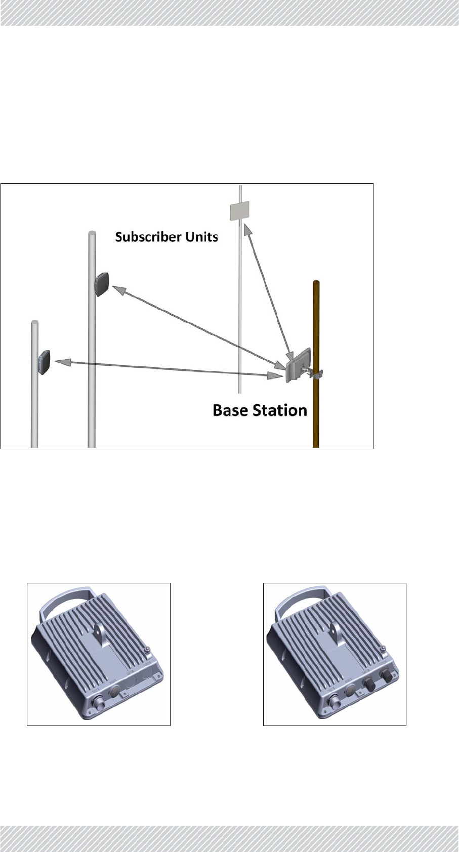
1.3.1Sector
TheRADWIN5000systemconsistsofa“sector”thatincludesabasestation,andatleastone
subscriberunit.Thesubscriberunitsareinstalledandworkoppositethebasestations.
Figure1‐1:ARADWIN5000Sector
1.3.2BaseStation
Therearethreetypesofbasestations,allofwhichareHighCapacityBaseStations(HBS):
•LargeFormFactor(LFF)‐Withanintegratedorexternalantenna
Figure1‐2:LFFbasestationwithinte‐
gratedantenna
Figure1‐3:LFFbasestationconnector‐
izedforexternalantenna
RADWIN5000InstallationGuide Release4.9.30 1‐3
SubscriberUnit Introduction
1.3.3SubscriberUnit
TherearetwotypesofRADWIN5000subscriberunits:
•High Capacity Subscriber Unit (HSU)
•SU PRO/AIR units
HighCapacitySubscriberUnit(HSU)
AnHSUcanhaveoneofthefollowingresourceallocations:
•CIR‐CommittedInformationRate:receivesaguaranteedpercentageof
resources
•BE‐BestEffort:receivesresourcesaccordingtoavailability
Inaddition,anHSUcanhaveoneofthefollowingformfactors:
• Beamforming(JET)‐Withanintegratedantenna
Figure1‐4:RADWIN5000JET
• Beamforming(DUO)‐Withanintegratedantenna
Figure1‐5:RADWINJETDUO
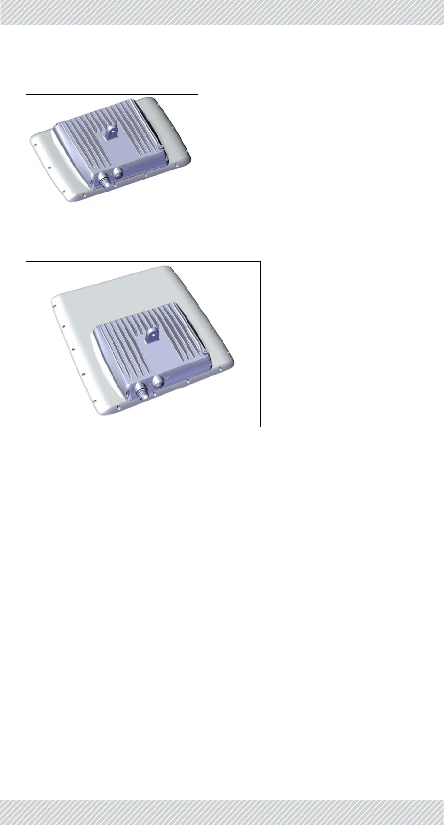
•LargeFormFactor(LFF)‐ItsexternalappearanceissimilartoaLargeFormFactor
HBS,andcanhaveanintegratedorexternalantenna.
RADWIN5000InstallationGuide Release4.9.30 1‐4
SubscriberUnit Introduction
SUPRO/AIRunits
•SUPRO‐CanoperateusingtheCIRorBEresourcetype
Figure1‐6:LFFsubscriberunitwith
integratedantenna
Figure1‐7:LFFsubscriberunitconnec‐
torizedforexternalantenna
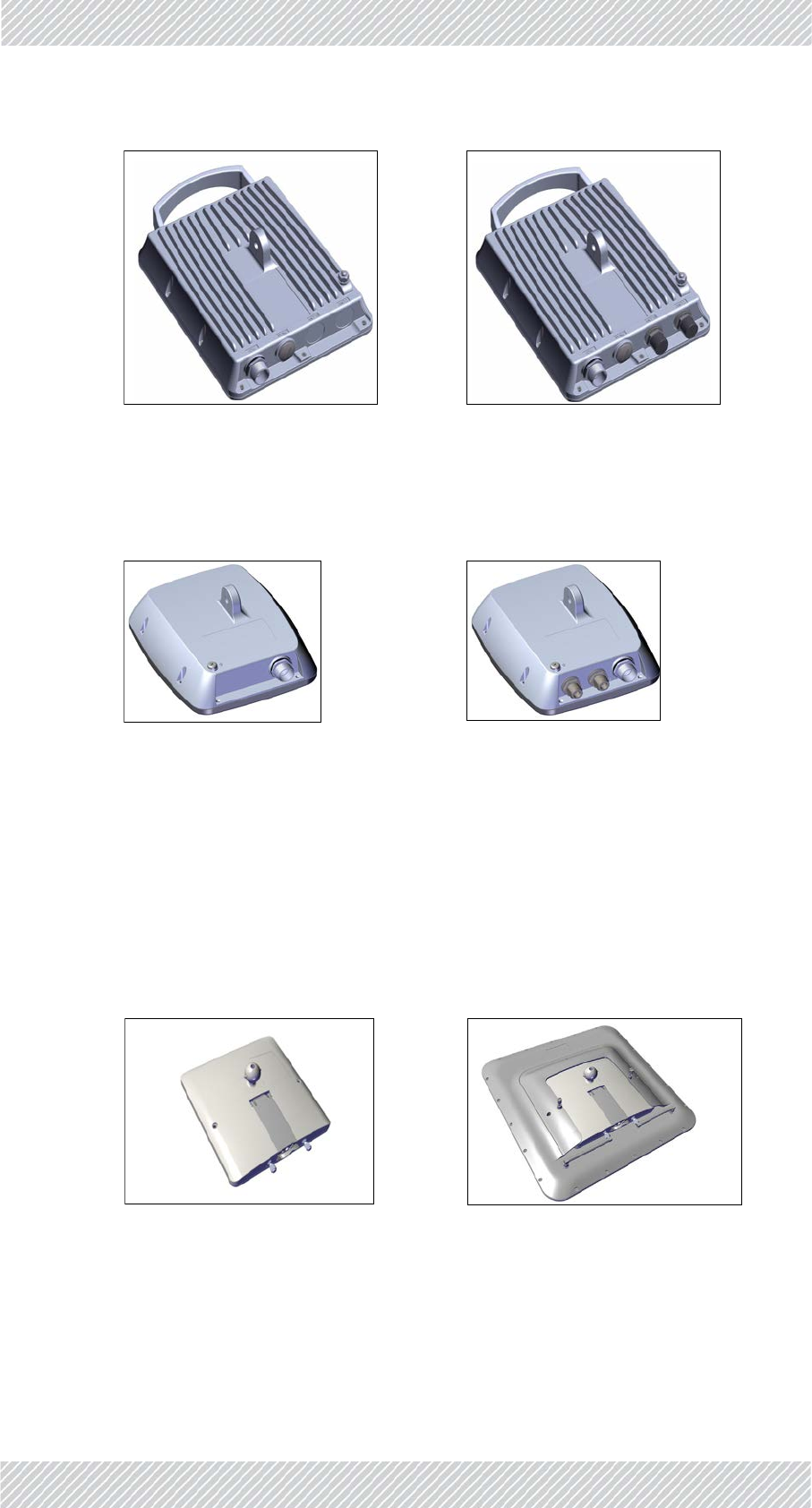
•SmallFormFactor(SFF)‐Asitsnameimplies,thisunitissmallerthananLFFunit,
butcanalsohaveanintegratedorexternalantenna.
Figure1‐8:SFFsubscriberunitwith
integratedantenna
Figure1‐9:SFFsubscriberstationcon‐
nectorizedforexternalantenna
•SUAIR‐OperatesusingtheBEresourcetypeonly.
•Usesasmallerform‐factorthanthatoftheHBSorHSU.
•Canuseanintegratedantenna,theTurboGainantennaoraseparate,non‐inte‐
grated,externalantenna.
Figure1‐10:SUPRO/AIRunitFigure1‐11:SUPRO/AIRunitwith
TurboGainantenna

RADWIN5000InstallationGuide Release4.9.30 1‐5
MethodofWork Introduction
1.3.4MethodofWork
Boththebasestationsandthesubscriberunitscommunicaterespectively,withtheservice
providerandusersthroughPoEdevices.Thecommunicationprotocolforboththeservice
providerandtheusersisEthernet.
Seefigure 1‐12,RADWIN5000ConnectionScheme:
•APoEdevice(orIDU‐H1)isconnectedtopowerandthecommunicationsnetwork:
•Onthebasestationside,thePoEisconnectedtothebackhaulnetwork
•Onthesubscriberunitside,thePoEisconnectedtoend‐userequipment:routers,
WiFidevices,etc.
•TheRADWINJETDUOcanhavetrafficandmanagementviaeitheritsPoEport,or
itsSFPdataport,butmuststillreceivevoltageviaaPoE.
•UsingCAT‐5ecables,theradiounitsareconnectedtopowerandthecommunications
networkviaaPower‐over‐Ethernet(PoE)device.
•TheradiounitsandPoEdevicesarealsoconnectedtoground.
•TheBaseStationcommunicateswiththeSubscriberUnitorUnitsviatheairinterface.
Figure1‐12:RADWIN5000ConnectionScheme
1. TheIDU‐Hdoesnotsupportbeam‐formingradios:JETorDUO
Forsimplicity,LightningProtectionUnits(LPU)arenotshowninFigure 1‐12,but
thesearerecommended.See“MountingtheLightningProtectionUnits”onpage
2‐27fordirectionsonhowtoinstalltheLPUs.
RADWIN5000InstallationGuide Release4.9.30 1‐6
SectorManagementTools Introduction
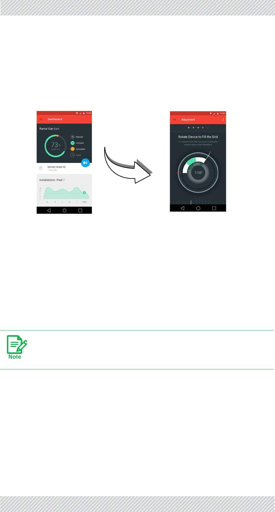
1.3.5SectorManagementTools
WINTouch
WINTouchisamobileapplicationthatguidesyouininstallingandaligningSUPRO/AIR
devices,aswellasbasestationsthatworkwiththem.
RADWINWebInterface
TheWebInterfaceenablesyoutocarryoutbasicunitand/orsectormanagementfunctions
usingaWebbrowser.Itisaneasywaytorapidlyconfigureandsetupalink.
Itmaybeusedto‐
•Setorchangebasicradiounitparametersinthefield
•Establishasectoronaminimalbasis
•Checklinkparametersandmakebasicchanges
•ViewthelinkInventory
•InspecttheRecentEventslogs
RADWINManager
TheRADWINManagerisanSNMP‐basedmanagementapplicationwhichmanagesa
completesectoroverasingleIPaddress.
TheWebInterfacefortheSUPRO/AIRandforlegacyHBSandHSUradiosare
different.

RADWIN5000InstallationGuide Release4.9.30 1‐7
KeyFeaturesofRADWIN5000 Introduction
1.4KeyFeaturesofRADWIN5000
1.4.1General
»Ethernetconnectivity
»AdvancedOFDM&MIMO2x2fornLOSandNLOSperformance
»Enhancedinterferencemitigationcapability
»Inter&intrasitesynctoreduceselfinterference
»Multibandradios:Differentfrequenciesinthesameradiounit
»DedicatedBandwidthensuringSLA&latency
»Regulationssupported‐FCC/IC/ETSI/WPC/MII/Universal
»Upto64SubscriberUnitsperbasestation
»FullyintegratedwithRADWINLegacysolutions:
•BasestationcancoexistwithRADWIN2000andWinLink1000products
•CommonRADWINManager
»Nomadicsupport(standardinallbasestationmodels)
1.4.2BeamformingSolutions(optional)
RADWIN5000JETandRADWINJETDUO
»Smartbeamformingantenna,integratedindedicatedbasestation
»On‐the‐flybeamformingcapabilityreducesinterference,increasesefficiency
»Narrowbeam
»Supportforethernet‐basedsynchronization
»IntegratedGPSsynchronizationcapability
RADWINJETDUO
»Dual‐bandplatformfor3.xand5.xGHzbands
•Availableconfigurationoffersasinglebandselectiononly
•Futureupgradeabletoconcurrentdual‐bands
»2x750Mbpswhenoperatedasadual‐bandsolution(softwareupgradeableby2018)
»UptoQAM256,2x80MHz
»Exceptionalinterferenceimmunitythrough2ndgen.beamformingantennawith
exceptionallysmallsidelobes
»Support64customers,upgradeableto2x64(softwareupgradeableby2018)
»Interfaces:Fiber(SFP)andGbE
1.5What’sNewinRelease4.9.30
»Newproduct:theRADWINJETDUOdualcarrierbasestation:abilitytoworkin
eitherthe3.xGHzbandor5.xGHzband,user‐configurable

RADWIN5000InstallationGuide Release4.9.30 1‐8
What’sNewinRelease4.9.30 Introduction
Forcompleteandcomprehensivecharacteristicsofthespecificmodelyouare
workingwith,refertoitsDataSheet.

RADWIN5000InstallationGuide Release4.9.30 2‐1
Chapter2:InstallationSteps
Toinstallandestablishabasicconnectionwitharadiounit,carryoutthestepsshownbelow.
Printoutthislist,andplaceacheckmarknexttoacompletedtask.
Table2‐1:InstallationCheck‐List
Step Action Page Done?
Beforedeployingatinstallationsite
1. PrepareLaptop page 2‐2
2. ConnectLaptoptoRadioUnit page 2‐2
3. UpdateConnectivityParametersofRadioUnit page 2‐5
4. Checkitemstobeinstalled page 2‐7
5. PrepareTools page 2‐7
Installation
6. InstallStandardMountingKit page 2‐8
7. InstallMountingKitfortheSUPRO/AIRRadioUnit page 2‐15
8. MountingaUnitwiththeStandardMountingKit page 2‐17
9. GroundRadioUnit page 2‐22
10. MountingtheSUPRO/AIRRadioUnit page 2‐25
11. MountingtheLightningProtectionUnits page 2‐27
12. ConnectExternalAntenna(ifapplicable) page 2‐30
13. Waterproofing page 2‐32
Commissioning
14. ConnectRadio(ExternalConnections) page 2‐33
15. CheckConnectivitytoRadio page 2‐39
16. ActivateBaseStation page 2‐39
17. AlignSubscriberUnit page 2‐40
RADWIN5000InstallationGuide Release4.9.30 2‐2
PrepareLaptop InstallationSteps
2.1PrepareLaptop
ConfigureIPaddressandsubnetmaskoflaptopasfollows:
•ControlPanel‐>NetworkandInternet‐>NetworkandSharingCenter‐>Change
Adaptersettings‐>clickonNetworkInterfaceCardname
•Properties‐>SelectInternetProtocolVersion4(TCP/IPv4)‐>Properties‐>setIPaddress
to10.0.0.100andSubnetmaskto255.255.0
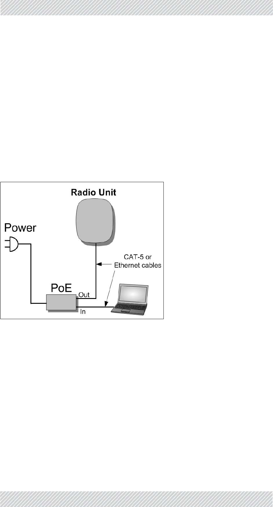
2.2ConnectLaptoptoRadioUnit
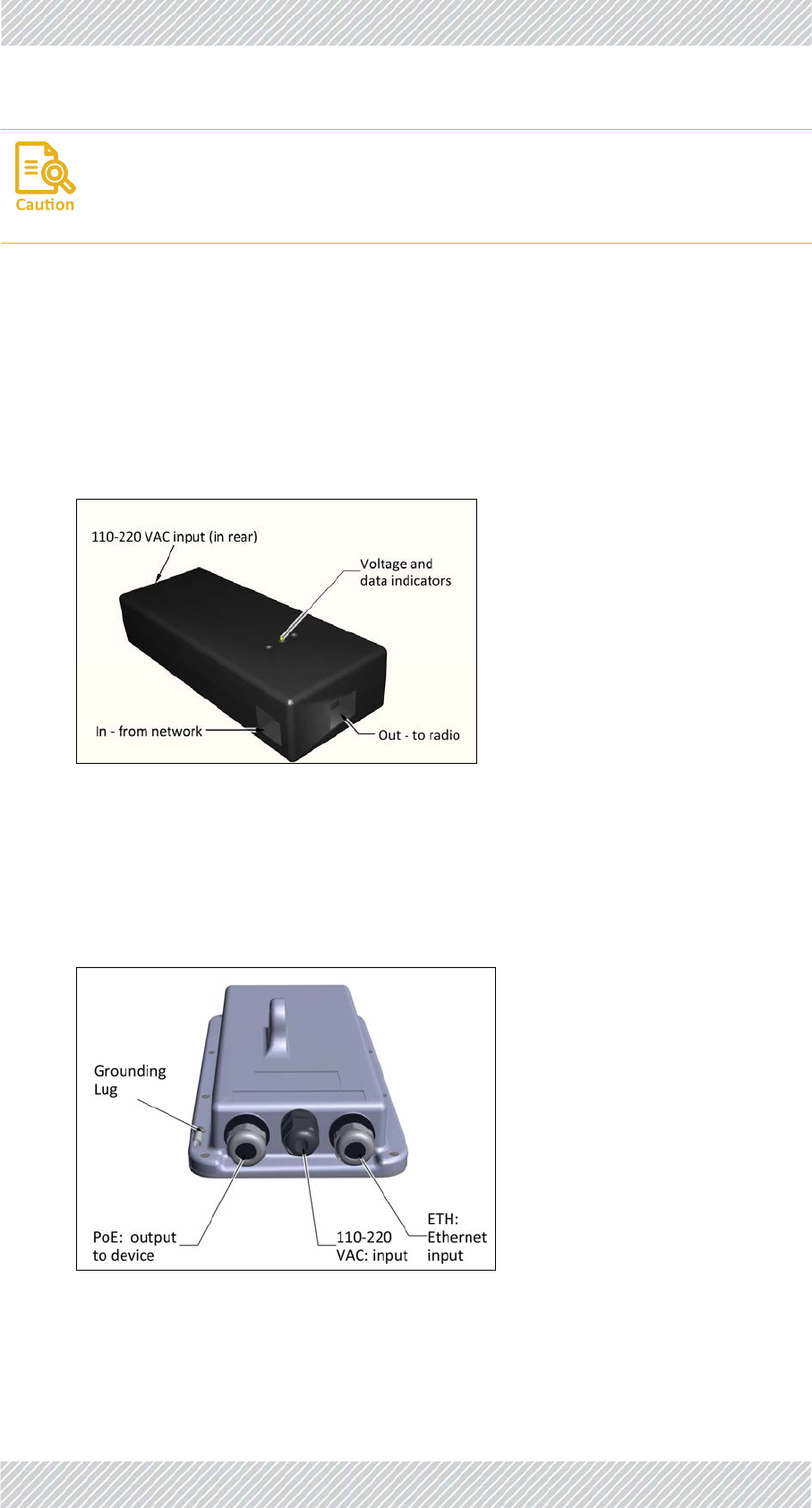
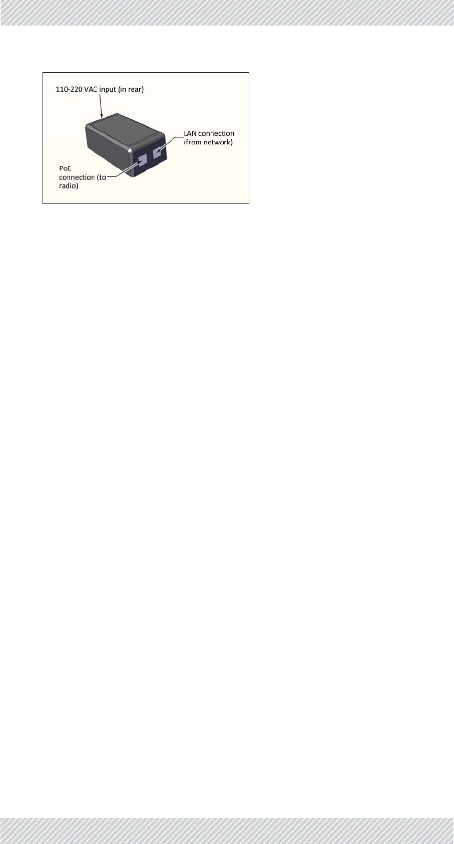
ConnectPoEtopower,connectthelaptop’sethernetporttotheIN(orLAN)socketonthe
PoE,thenconnecttheOUT(orPoE)socketonthePoEtotheappropriatesocketontheradio
unit.MakesureyouareusingtheappropriatePoEforyourspecificradiounit.
Figure2‐1:Connectinglaptoptoaradiounit
RADWIN5000InstallationGuide Release4.9.30 2‐3
RADWIN5000(LFFandSFF)Units InstallationSteps
2.2.1RADWIN5000(LFFandSFF)Units
Connecttosocketlabeled‐>“IDU”
Figure2‐2:Laptop/networkport:LFFradiounit(connectorizedunitshown)
Figure2‐3:Laptop/networkport:SFFradiounit(connectorizedunitshown)
RADWIN5000InstallationGuide Release4.9.30 2‐4
JETandDUOUnits InstallationSteps
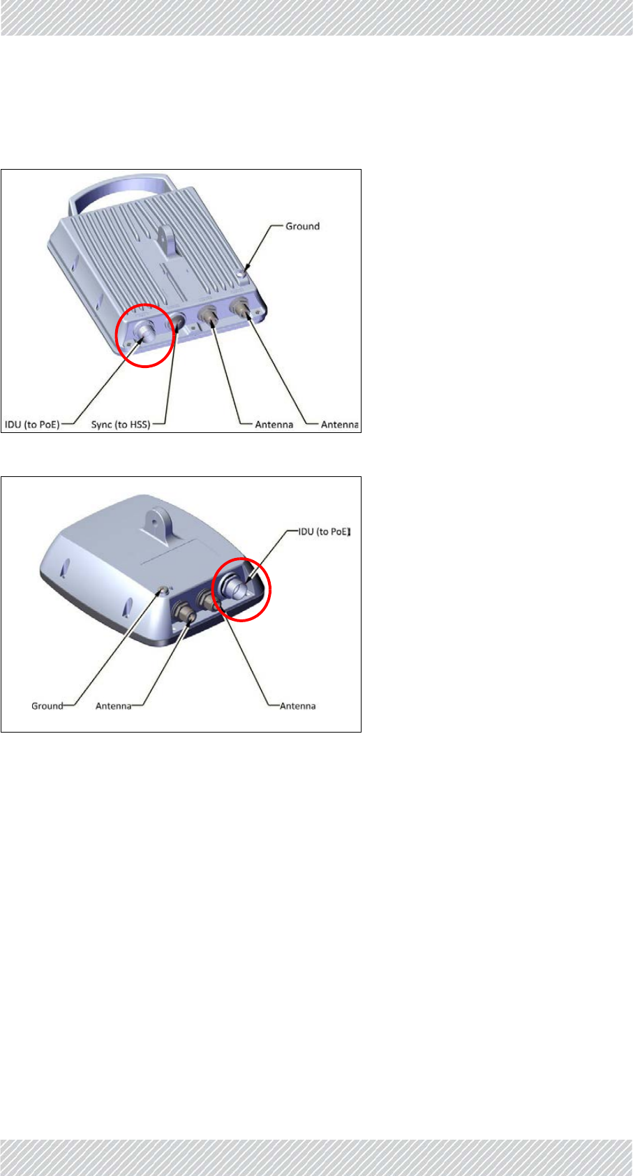
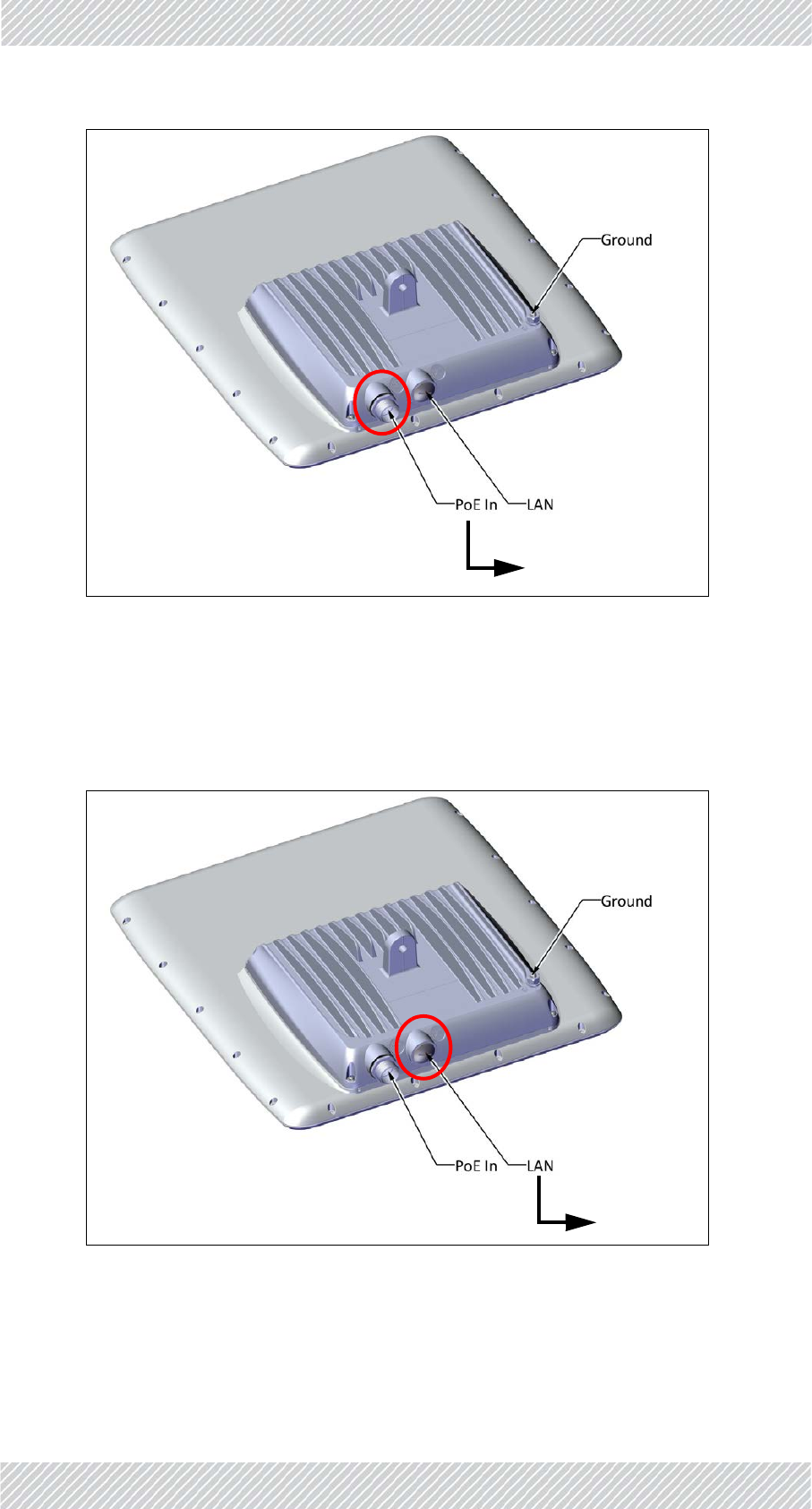
2.2.2JETandDUOUnits
Connecttosocketlabeled‐>“PoEIn”
Figure2‐4:Laptop/networkport:JETradiounit
Figure2‐5:Laptop/networkport:DUOradiounit
RADWIN5000InstallationGuide Release4.9.30 2‐5
SUPRO/AIRUnits InstallationSteps
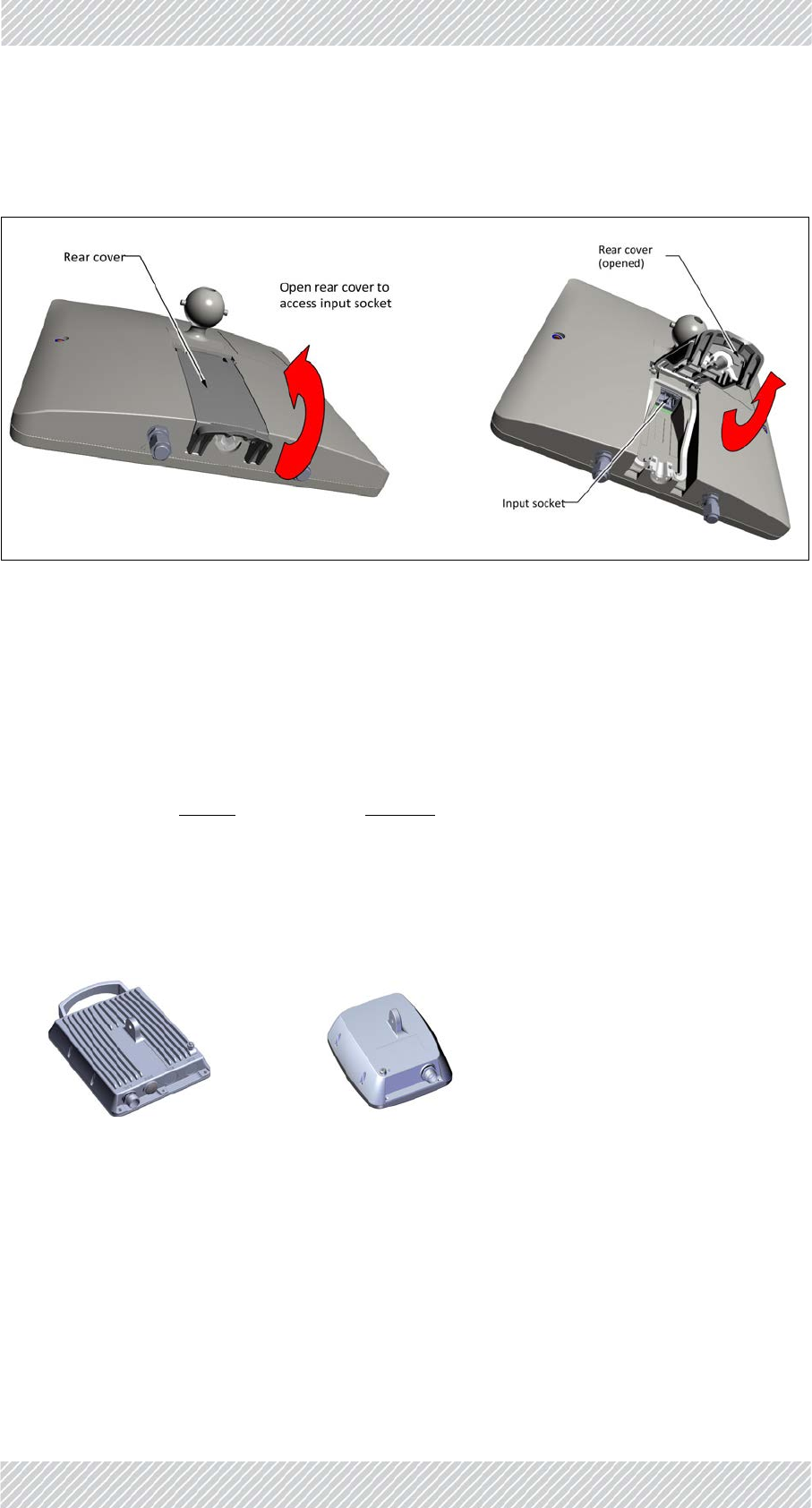
2.2.3SUPRO/AIRUnits
Connectto‐>Inputsocket(notlabeled)
Figure2‐6:Laptop/networkport:SUPRO/AIRradiounit
2.3UpdateConnectivityParametersofRadio
Unit
1. Inaninternetbrowser,enterhttp://10.0.0.120
2. EnterUserNameadminandPasswordnetman.
3. ClickLogIn.
4. Continueaccordingtothetypeofradiounityouareusing:
2.3.1HSU:RADWIN5000(LFForSFFradiounits)
a. ClickConfig.
b. ClickManagement.
c. EnternewIPAddress,SubnetMask,andDefaultGateway.
d. ClickSaveandexitbrowser.
e. Fromacommandline,pingradiounitusingnewIPaddresstoverifychange.
RADWIN5000InstallationGuide Release4.9.30 2‐6
HBS:RADWIN5000,JET,orDUOradiounits InstallationSteps
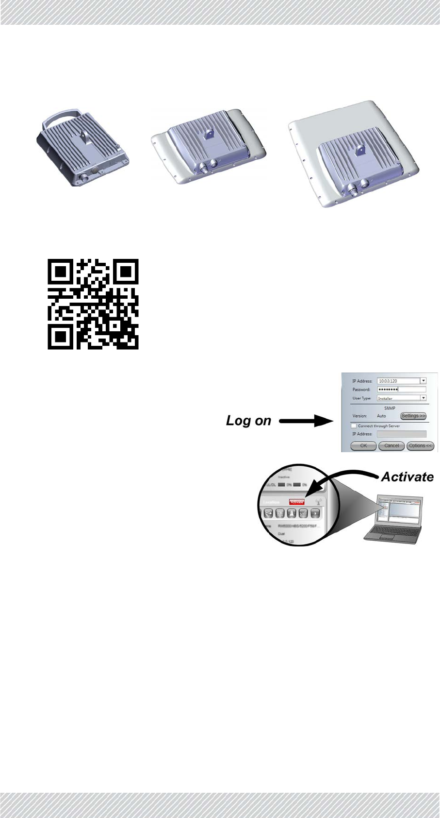
2.3.2HBS:RADWIN5000,JET,orDUOradiounits
a. InstalltheRADWINManagerapplicationfrom:http://www.radwin.com/
download,orusetheQRcode:
b. LogontotheRADWINManageras
an“Installer”andenterthedefault
IPaddress(http://10.0.0.120)and
password:wireless.
c. FromtheRADWINManager,click
Activate,andfollowtheinstructionsin
thewizard.
d. Duringthecourseofthewizard,enterthe
newmanagementIPAddress,Subnet
Mask,andDefaultGateway,SectorID,
operatingchannel,andchannel
bandwidth.
e. Fromacommandline,pingradiounitusingnewIPaddresstoverifychange.
f. Onceyouarefinishedwiththestepsabove,disconnecttheradiounitandprepareit
fordeploymentinthefield.

RADWIN5000InstallationGuide Release4.9.30 2‐7
SUPRO/AIRUnits InstallationSteps
2.3.3SUPRO/AIRUnits
a. ClickConfigure
b. ClickNetwork
c. EnternewIPAddress,SubnetMask,andDefaultGateway.
d. ClickApplyAllandexitbrowser.
e. Fromacommandline,pingradiounitusingnewIPaddresstoverifychange.
f. Onceyouarefinishedwiththestepsabove,disconnecttheradiounitandprepareit
fordeploymentinthefield.
2.4Checkitemstobeinstalled
•Radiounit+mountingkit
•2LPUsforeachradio(recommended)
•PoE(ifoutdoor,requiresmountingkit)
•CAT‐5ecables
•Groundingcables(10AWG)forradiounit,LPUsandoutdoorPoE(ifused)
•Externalantenna+mountingkit(ifusinganexternalantennaforLFForSFFunits)
•RFcables(ifusinganexternalantennaforLFForSFFunits)
•TurboGainantenna(ifusingthisantennafortheSUPRO/AIRunit)
2.5PrepareTools
•Crimpingtool
•Spanner/wrench13mm(1/2”)
•Cableties
•Sealingmaterial
•Waterproofingtape(likeScotch23)
Alternatively,youcanusetheWINTouchsmartphoneapplicationtochangetheIP
address.LogontoWINTouchandfollowtheinstructions.
RADWIN5000InstallationGuide Release4.9.30 2‐8
InstallStandardMountingKit InstallationSteps
2.6InstallStandardMountingKit
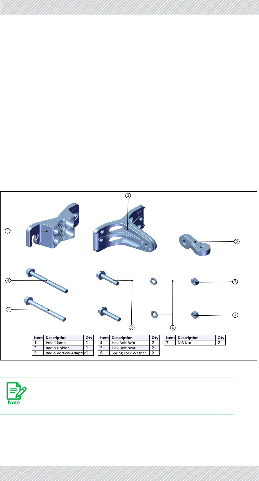
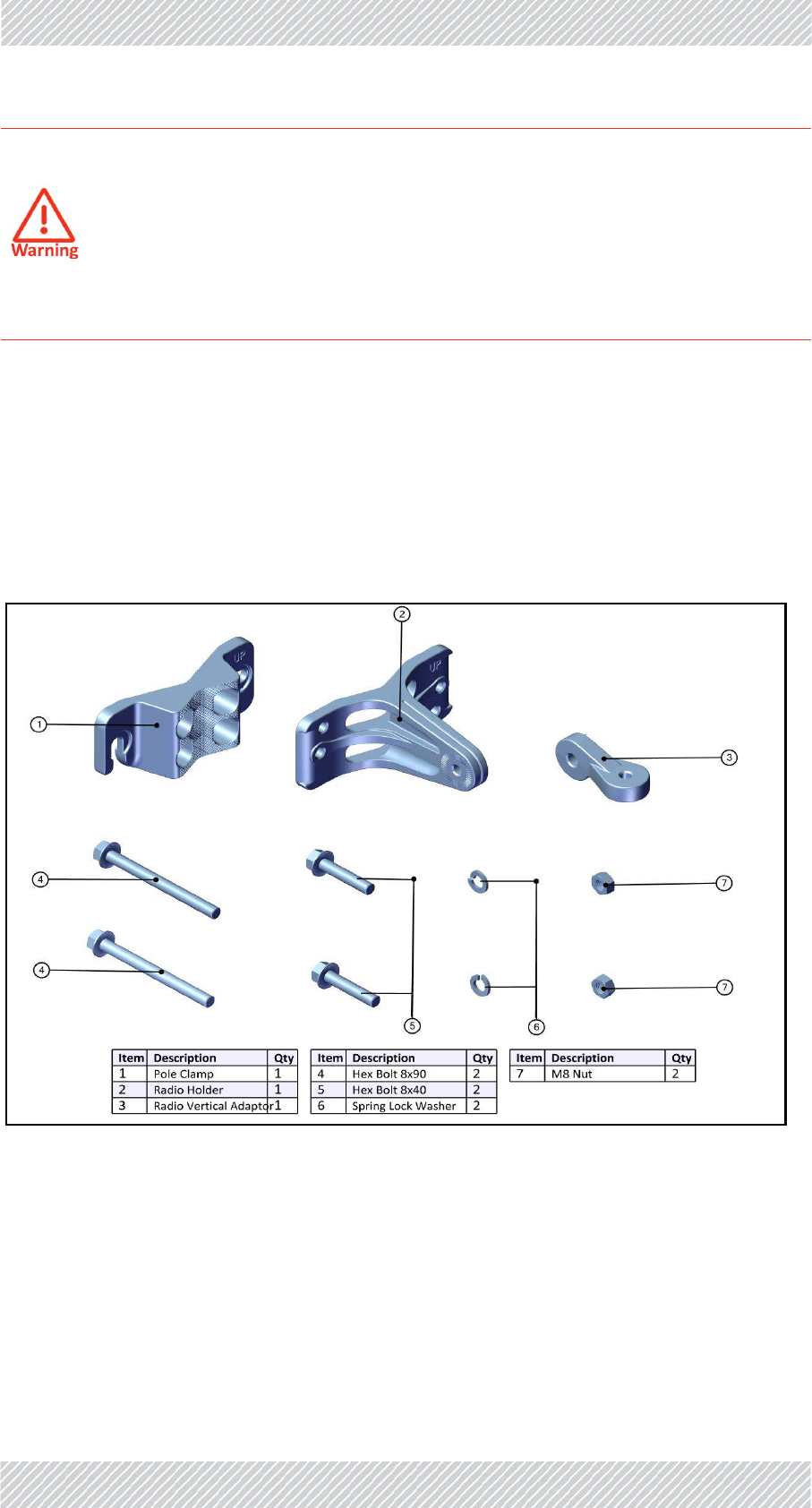
2.6.1StandardMountingKit
Usethestandardmountingkitfor:
•LFF(largeform‐factor)radiounits
•SFF(smallform‐factor)radiounits
•JETradiounits
•DUOradiounits
•ExternalPoEs
•RADWINGSUs
•Externalantennas(withmountingkitadaptor)
TheSUPRO/AIRhasitsownmountingkit:seeInstallMountingKitfortheSUPRO/AIRRadio
Unitonpage 2‐15.
Figure2‐7:MountingKitContents
Tightenallboltswithatorqueof15Nm.
RADWIN5000InstallationGuide Release4.9.30 2‐9
VerticalPole InstallationSteps
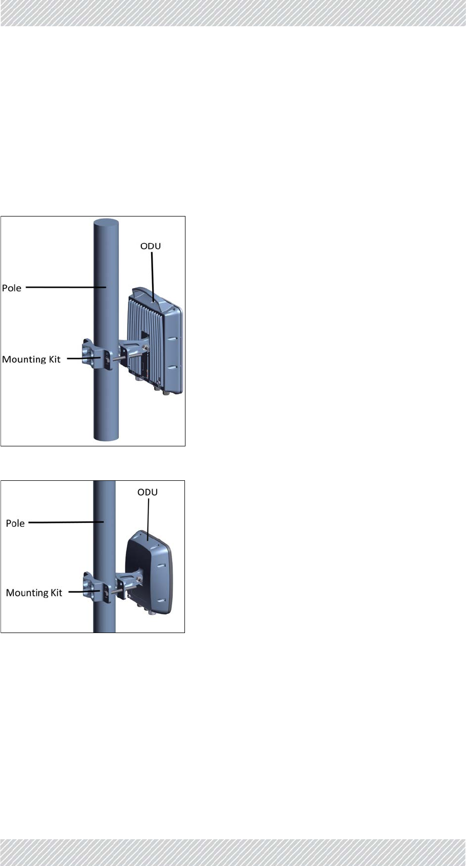
Themountingkitcanbeusedonaverticalorhorizontalpoleoronawall:
2.6.2VerticalPole
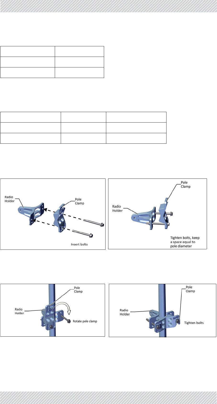
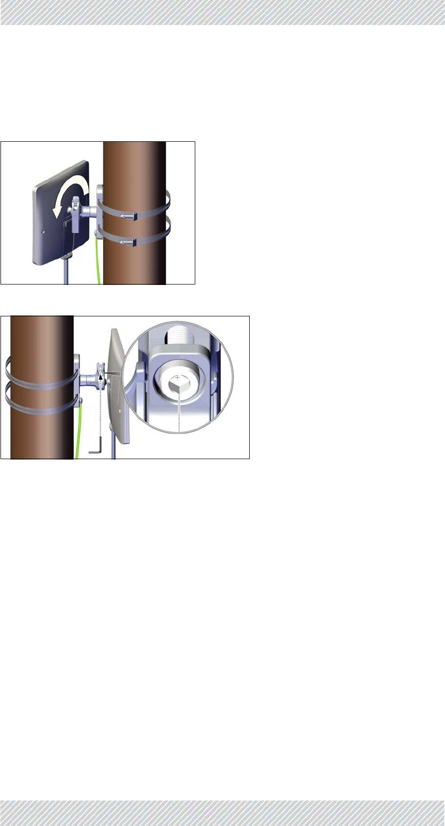
Themountingkitcanbeusedonathin,medium,orthickpole.
ThinPole
1. Diameter3/4to11/2:Positionthepoleclampasshowninthefollowingfigures.
Donottightentheboltsalltheway.
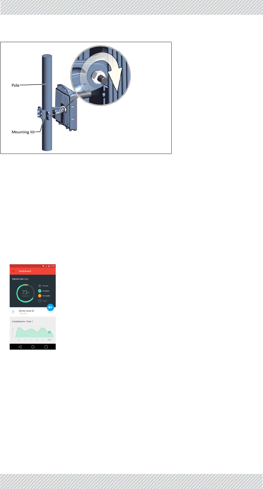
2. Placethis“unit”onthepolewhereyouwanttomountthedevice.Onceitisin
place,rotatethepoleclampasshown,thentightenbothbolts.
VerticalPolepage 2‐9
HorizontalPole page 2‐12
Wall page 2‐14
ThinPole Dia.3/4‐11/2 page 2‐9
MediumPole Dia.2‐3page 2‐10
ThickPole Dia.>3page 2‐10
Figure2‐8:ConnectPoleClamptoRadio
Holder
Figure2‐9:Partiallytightenbolts
Figure2‐10:RotateClampandtightenbolts Figure2‐11:Completelytightenbolts
RADWIN5000InstallationGuide Release4.9.30 2‐10
VerticalPole InstallationSteps
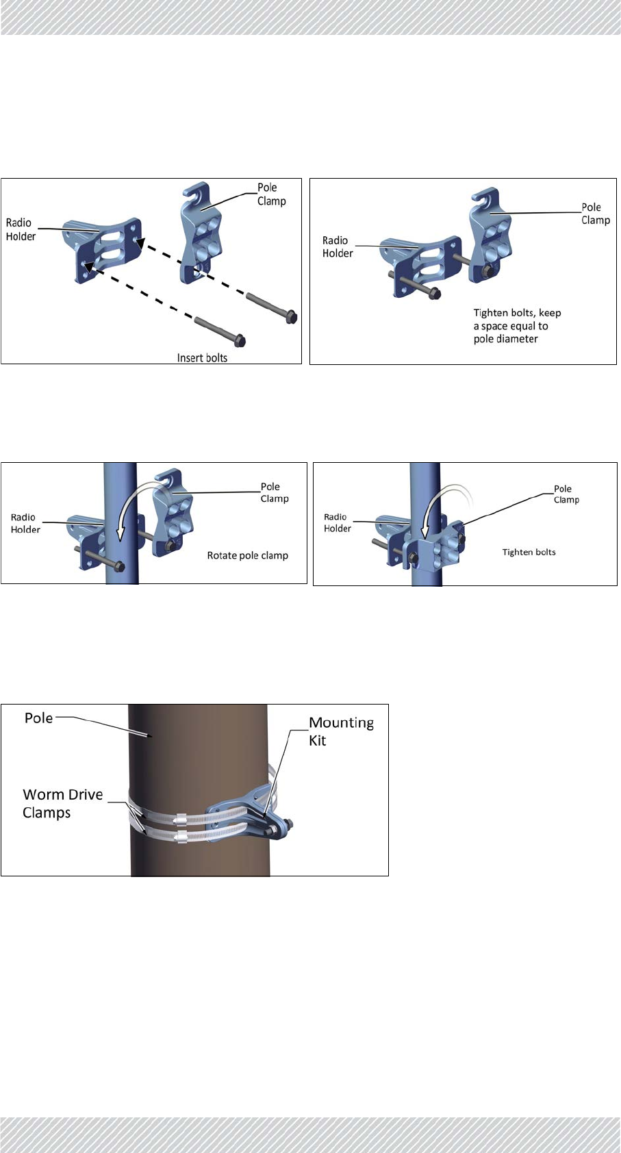
MediumPole
1. Diameter2to3:Positionthepoleclampasshowninthefollowingfigures.Donottighten
theboltsalltheway.
2. Placethis“unit”onthepolewhereyouwanttomountthedevice.Onceitisin
place,rotatethepoleclampasshown,thentightenbothbolts.
ThickPole
1. Diameterlargerthan3:Usewormdriveclamps(notsupplied),threadedthroughtheholes
asshown:
Figure2‐16:Mountingkitonathickpole
Thepoleclampisnotneeded.
Figure2‐12:ConnectPoleClamptoRadio
Holder
Figure2‐13:Tightenbolts
Figure2‐14:RotateClamp Figure2‐15:Completelytightenbolts
RADWIN5000InstallationGuide Release4.9.30 2‐11
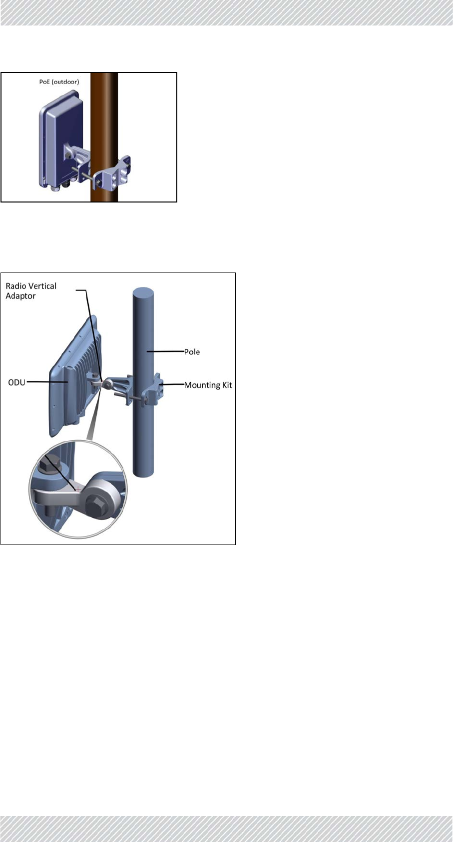
VerticalPole InstallationSteps
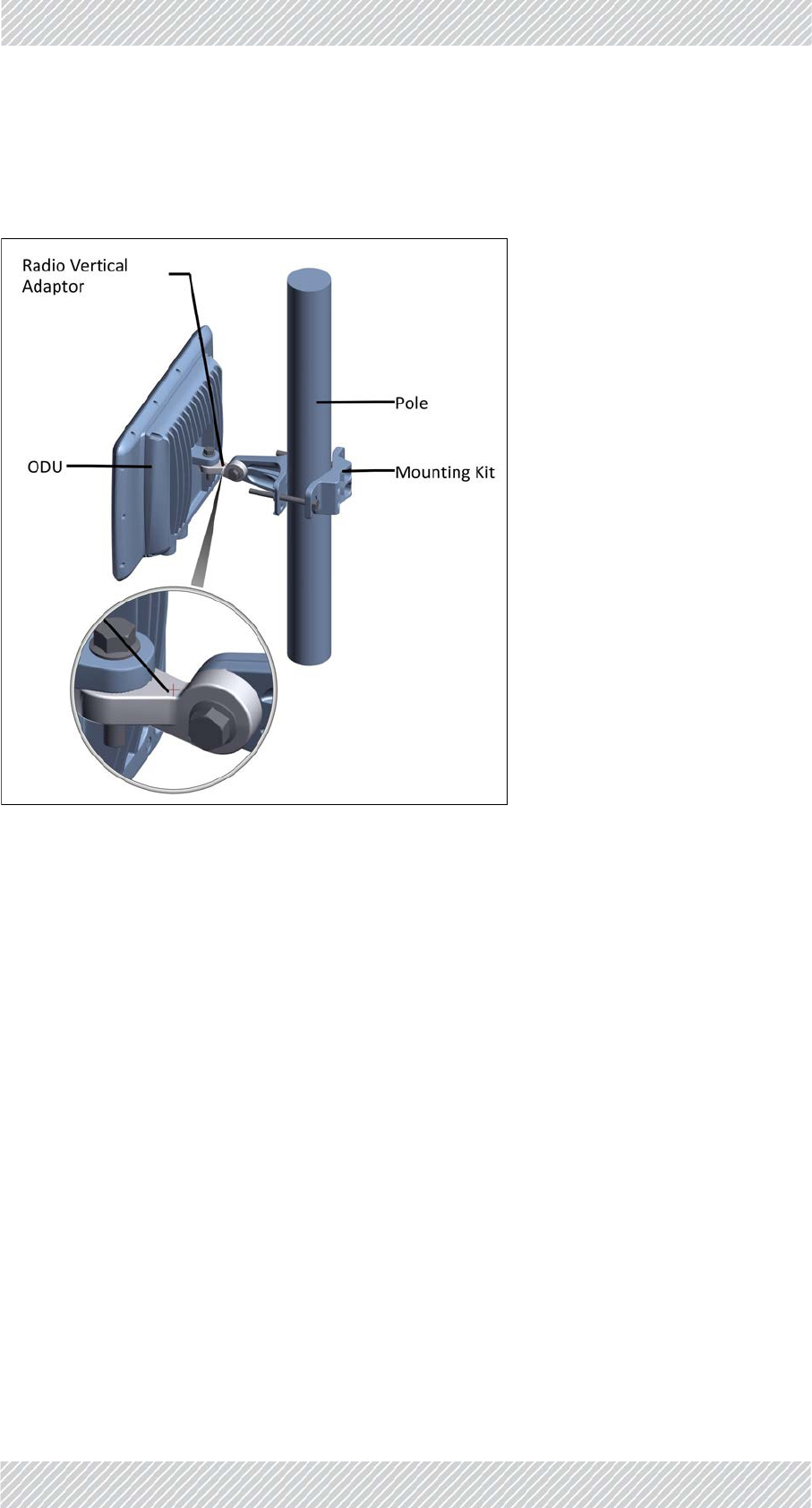
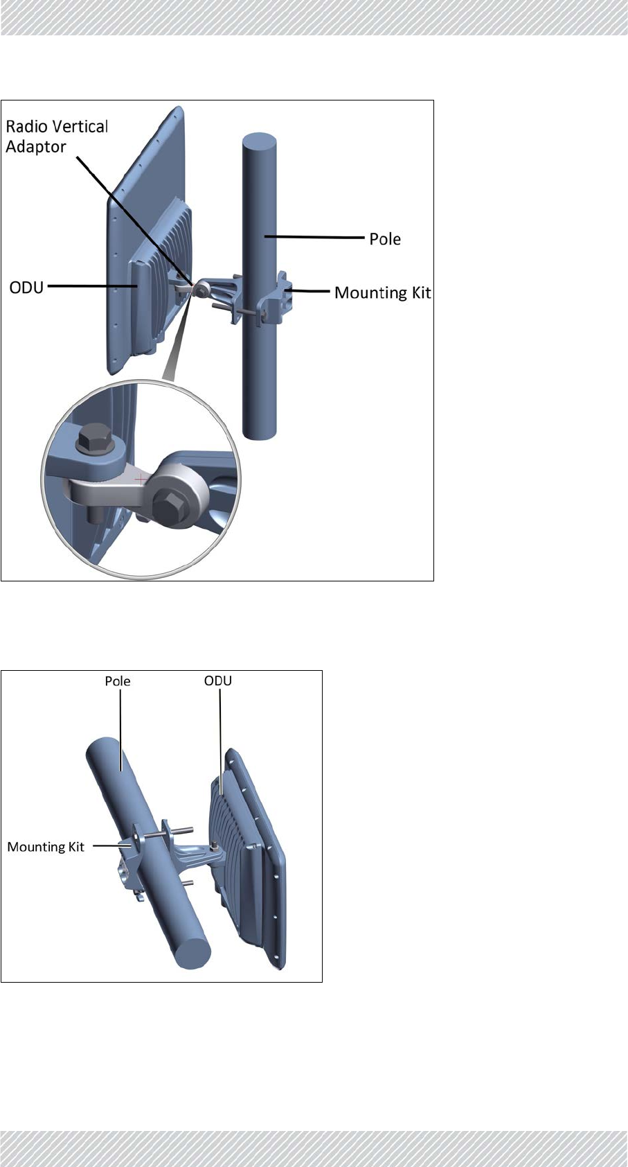
JETandDUORadioUnits
WhenmountingaJETorDUOradiounitonaverticalpole,usetheradioverticaladaptoras
shown:
Figure2‐17:JETradiounitmountedonaverticalpole
RADWIN5000InstallationGuide Release4.9.30 2‐12
HorizontalPole InstallationSteps
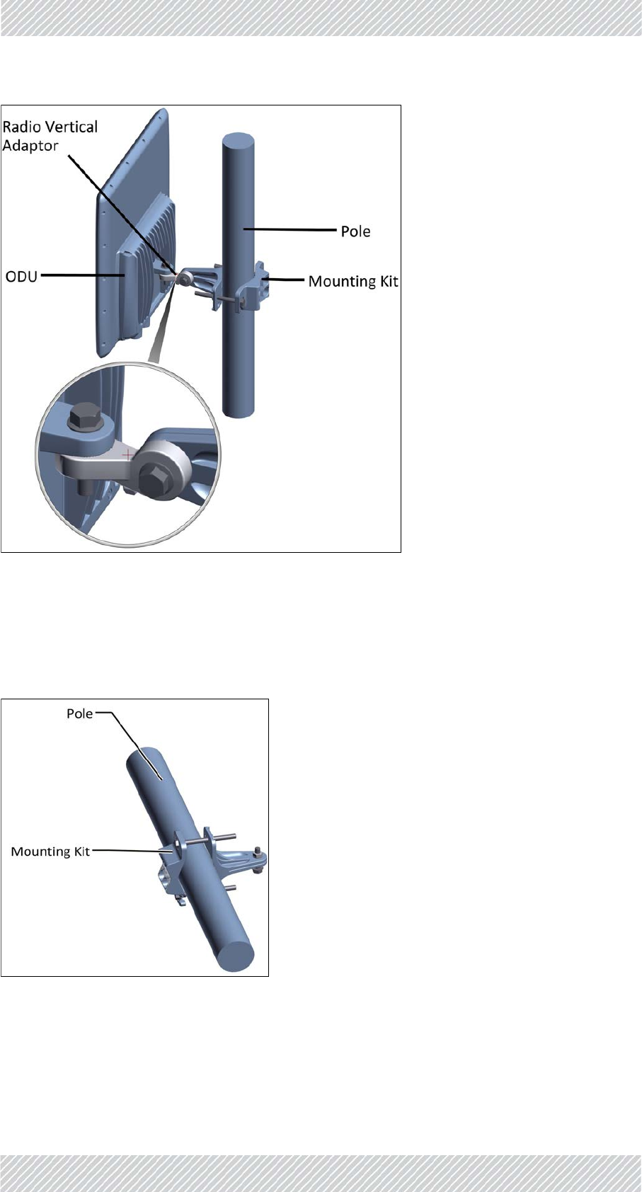
Figure2‐18:DUOradiounitmountedonaverticalpole
2.6.3HorizontalPole
Installingthemountingkitonahorizontalpoleisdoneinasimilarmannertothatona
verticalpole(thin,medium,orthicksizes):
Figure2‐19:MountingKitonahorizontalpole
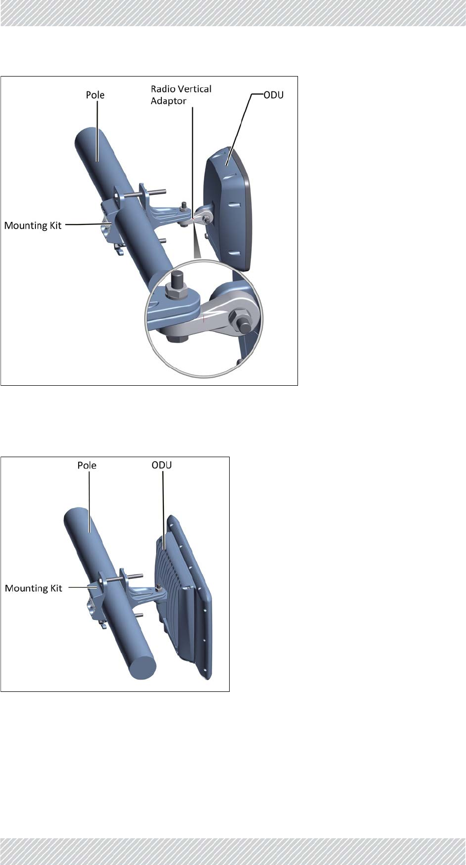
WhenmountingaLargeForm‐Factor(LFF)radiounit,SmallForm‐Factor(SFF)radiounit,GSU,
PoE,orexternalantennaonahorizontalpole,usetheradioverticaladaptor:
RADWIN5000InstallationGuide Release4.9.30 2‐13
HorizontalPole InstallationSteps
Figure2‐20:Radiounitmountedonahorizontalpole
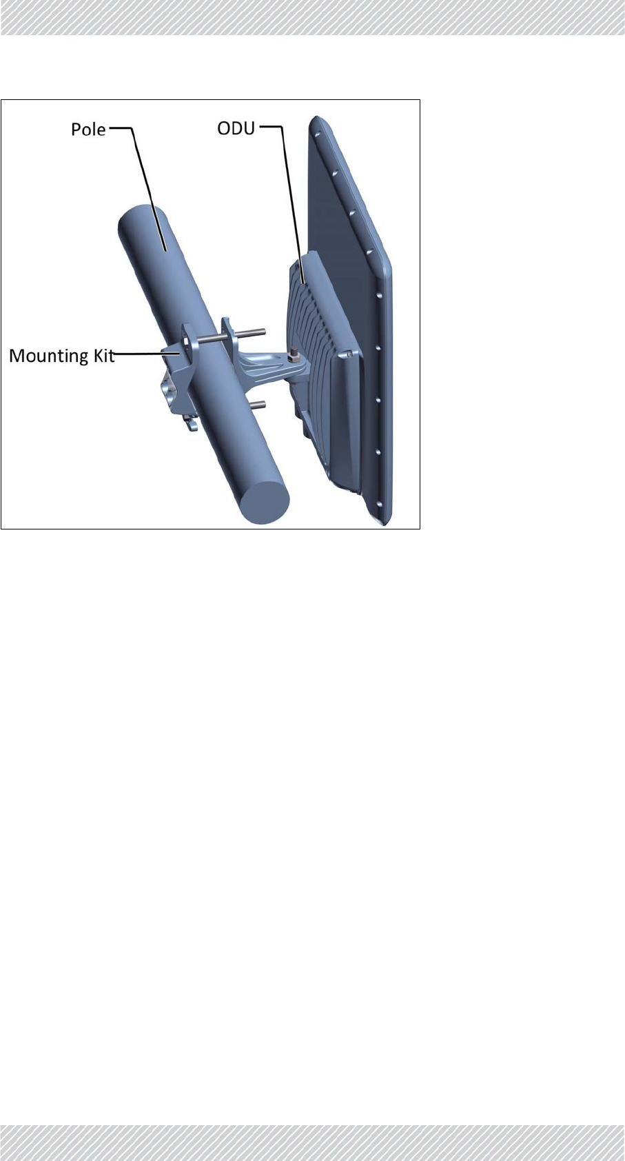
WhenmountingaJETorDUOradiounitonahorizontalpole,theverticaladaptorisnot
needed:
Figure2‐21:JETradiounitmountedonahorizontalpole
RADWIN5000InstallationGuide Release4.9.30 2‐14
Wall InstallationSteps
Figure2‐22:DUOradiounitmountedonahorizontalpole
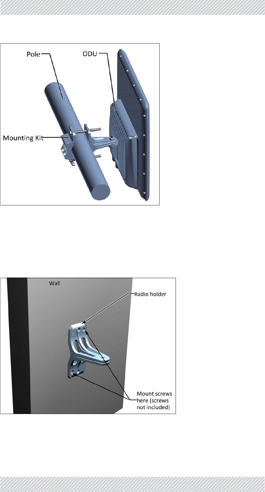
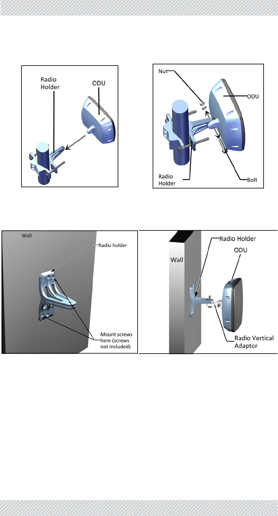
2.6.4Wall
Usetwomountingscrews(notincluded)appropriateforthetypeofwalltoinstallthe
mountingkitonawall.Makesureyouusetheindicatedholes.
Thepoleclampisnotneeded.
Figure2‐23:Mountingkitonawall
RADWIN5000InstallationGuide Release4.9.30 2‐15
InstallMountingKitfortheSUPRO/AIRRadioUnit InstallationSteps
2.7InstallMountingKitfortheSUPRO/AIR
RadioUnit
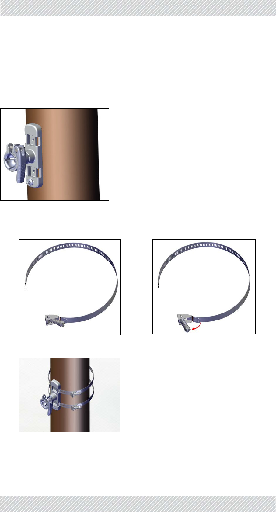
TheSUPRO/AIRhasitsownmountingkit.Mountthisunitasshowninthestepsbelow:
1. Placethemountonapoleorwall:
2. Securethemountusingthewormdriveclamps.Theseare“quick‐release”clamps,
andworkasfollows:
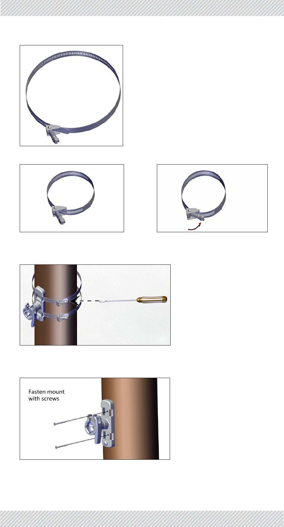
a. Opentheclamp:
b. Slidethemetalbandthroughthemount:
c. Slidethemetalbandthroughtheclamp:
RADWIN5000InstallationGuide Release4.9.30 2‐16
InstallMountingKitfortheSUPRO/AIRRadioUnit InstallationSteps
d. Adjusttheradiusoftheband,andlockitwiththeclamp:
e. Oncethebandisatthecorrectradius,closetheclampandtightenwitha
screwdriver(makesurethetopsofthescrewsfaceawayfromthemount):
3. Alternatively,youcanfastenthemountwithscrews(notincluded)appropriatefor
thesurfacebeingused:
RADWIN5000InstallationGuide Release4.9.30 2‐17
MountingaUnitwiththeStandardMountingKit InstallationSteps
2.8MountingaUnitwiththeStandard
MountingKit
FastenanLFF(largeform‐factor),SFF(smallform‐factor)JETradiounits,aswellasexternal
PoEs,andRADWINGSUs,andexternalantennastothemountingkitasshowninFigure 2‐24
toFigure 2‐26:
(ifmountingaflat‐panelantenna,seepage 2‐21).
Figure2‐24:MountedLFFradiounit
Figure2‐25:MountedSFFradiounitorGSU
RADWIN5000InstallationGuide Release4.9.30 2‐18
MountingaUnitwiththeStandardMountingKit InstallationSteps
Figure2‐26:MountedPoE
ForJETradiounits,mountasshowninFigure 2‐27andFigure 2‐29:
•UsetheradioverticaladaptorwhenmountingaJETorDUOunitonaverticalpole
Figure2‐27:JETradiounitmountedonaverticalpole
RADWIN5000InstallationGuide Release4.9.30 2‐19
MountingaUnitwiththeStandardMountingKit InstallationSteps
Figure2‐28:DUOradiounitmountedonaverticalpole
•WhenmountingaJETorDUOunitonahorizontalpole,theradioverticaladaptorisnot
needed:
Figure2‐29:JETradiounitmountedonahorizontalpole
RADWIN5000InstallationGuide Release4.9.30 2‐20
MountingaUnitwiththeStandardMountingKit InstallationSteps
Figure2‐30:DUOradiounitmountedonahorizontalpole
RADWIN5000InstallationGuide Release4.9.30 2‐21
MountingaUnitwiththeStandardMountingKit InstallationSteps
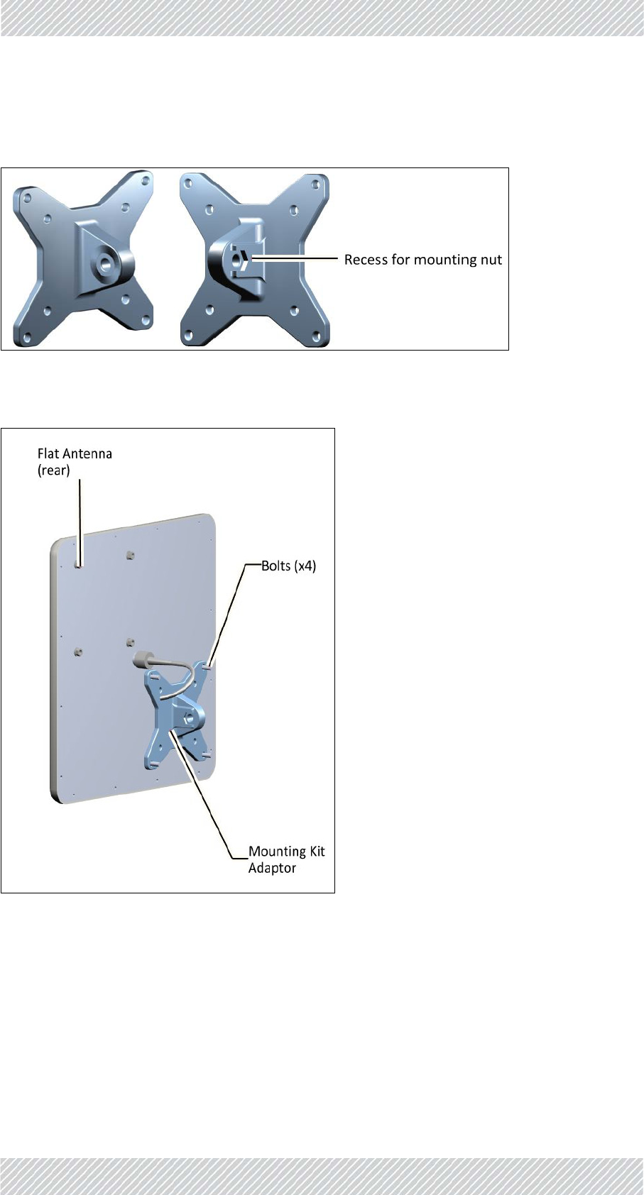
Flatpanelantenna
Ifmountingaflatpanelantenna,amountingkitadapterisrequired(seeFigure 2‐31):
Figure2‐31:Flatpanelantennamountingkitadapter
Attachthemountingkitadaptortotherearoftheexternalantennaasshown:
Figure2‐32:FlatPanelantenna‐rearwithmountingkitadapter
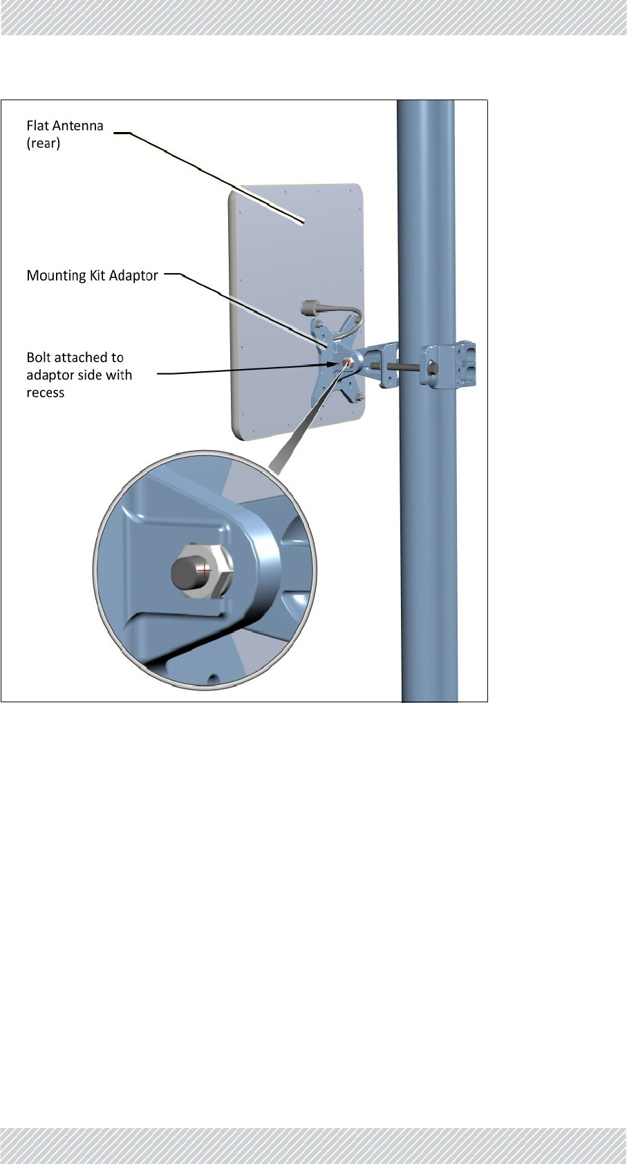
Mounttheantennawiththeadaptortoaverticalorhorizontalpole(asshowninFigure 2‐24
toFigure 2‐25).
Figure 2‐33showsamountedantenna.Attachthemountingbolttothesideoftheadaptor
withtherecess,asshown.
RADWIN5000InstallationGuide Release4.9.30 2‐22
GroundRadioUnit InstallationSteps
Figure2‐33:FlatPanelantenna‐mountedonapole
2.9GroundRadioUnit
Connectagroundcabletotheindicatedgroundconnectionontheradiounitasshowninthe
sectionsbelow:
RADWIN5000InstallationGuide Release4.9.30 2‐23
LFFUnits InstallationSteps
2.9.1LFFUnits
Figure2‐34:Ground:LFFradiounit
2.9.2SFFUnits
Figure2‐35:Ground:SFFradiounit
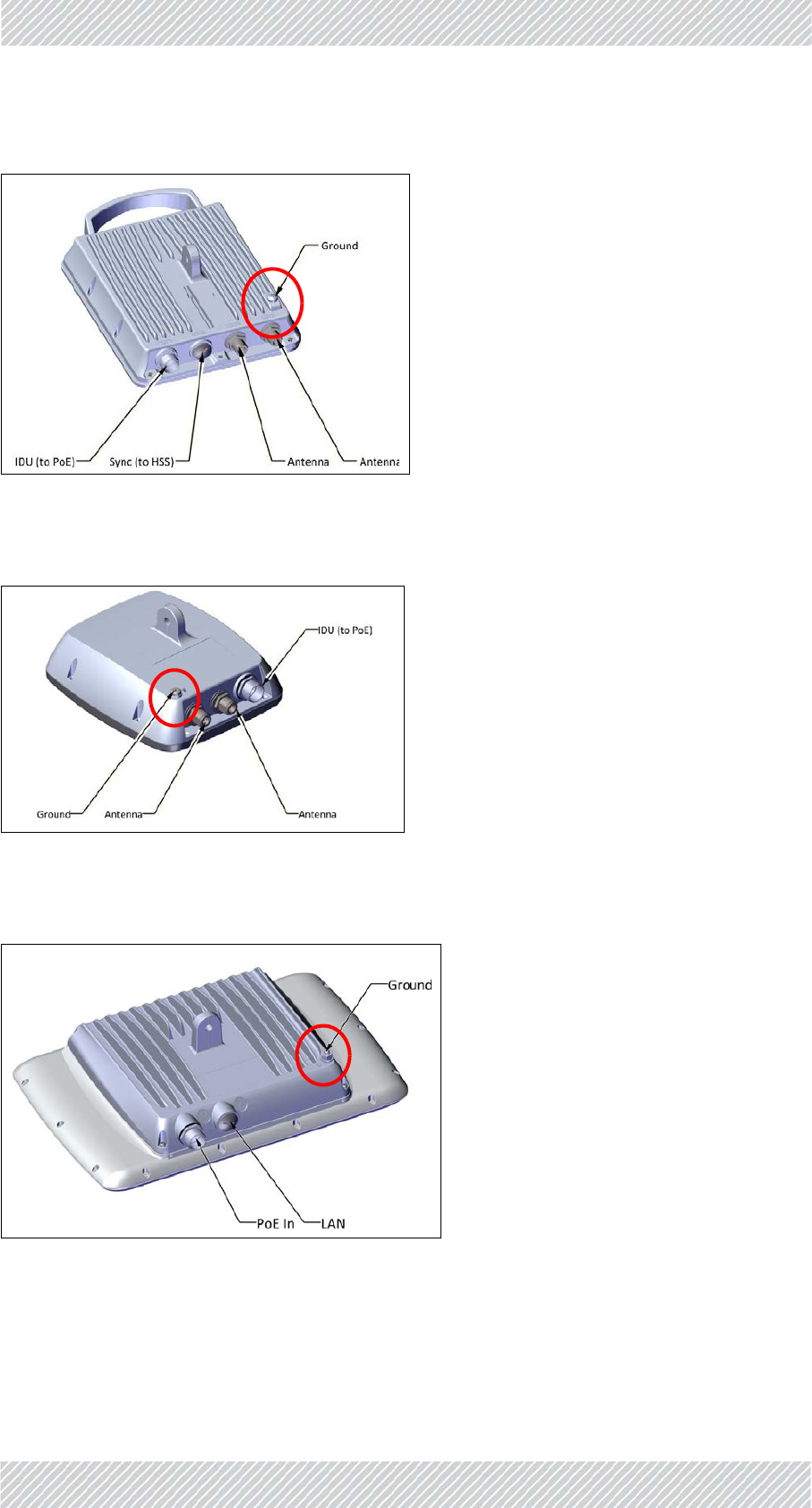
2.9.3JETUnits
Figure2‐36:Ground:JETradiounit
RADWIN5000InstallationGuide Release4.9.30 2‐24
DUOUnits InstallationSteps
2.9.4DUOUnits
Figure2‐37:Ground:DUOradiounit
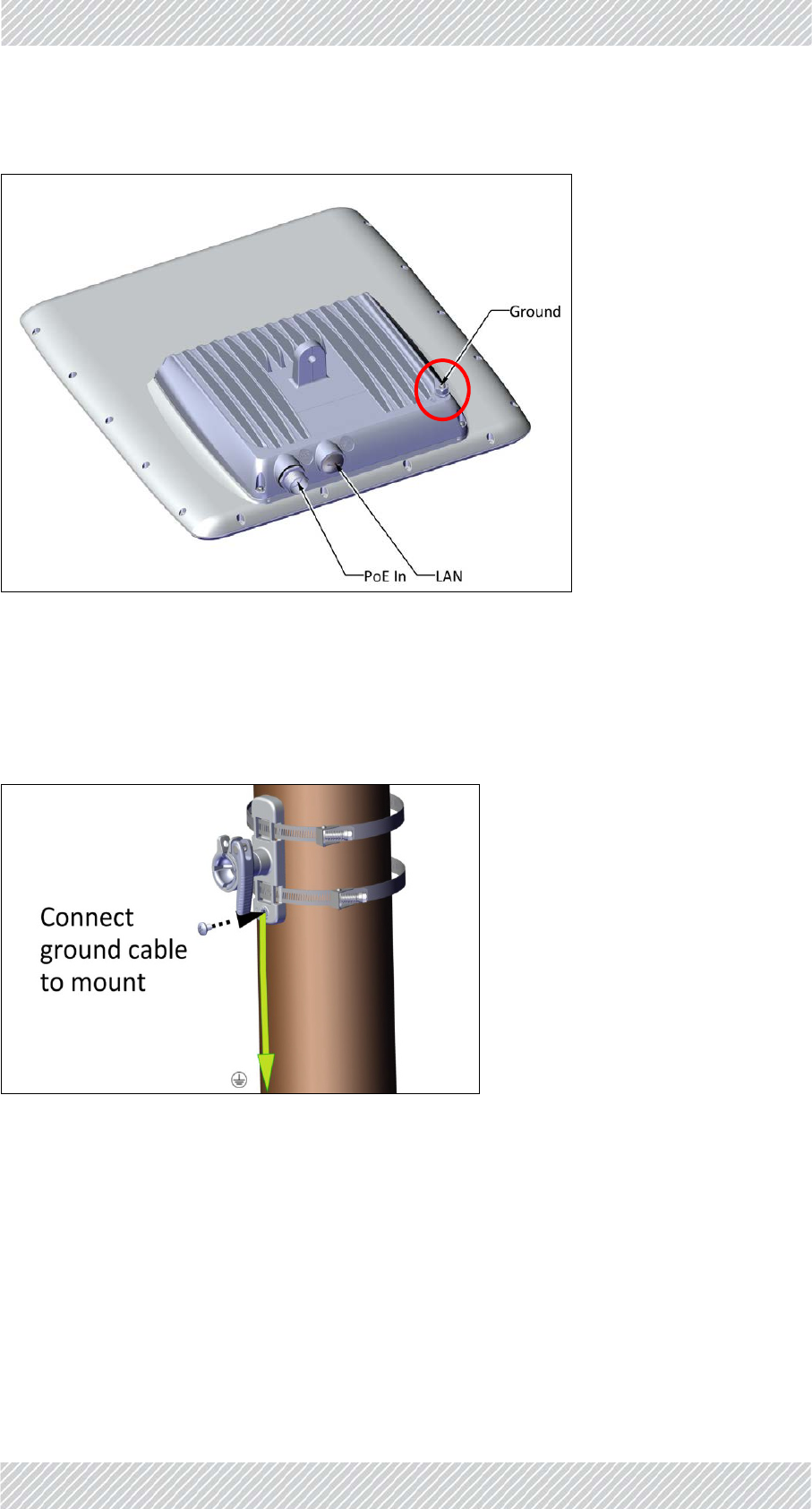
2.9.5SUPRO/AIRUnits
SincetheSUPRO/AIRisgroundedviaitsmountingkit,itmustbegroundedbeforebeing
mounted.
Figure2‐38:Ground:SUPRO/AIRradiounit
RADWIN5000InstallationGuide Release4.9.30 2‐25
MountingtheSUPRO/AIRRadioUnit InstallationSteps
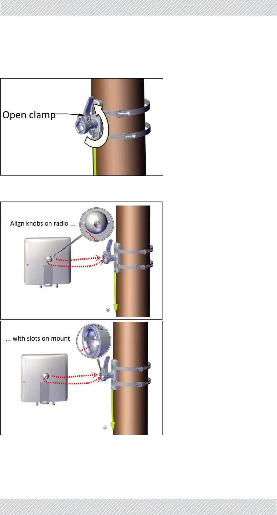
2.10MountingtheSUPRO/AIRRadioUnit
1. Opentheclamp(forradiounit):
2. Positiontheradiounitsothattheknobsonthemountingballontherearare
oppositetheslotsonthemount:
RADWIN5000InstallationGuide Release4.9.30 2‐26
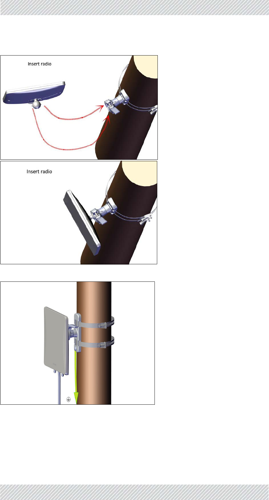
MountingtheSUPRO/AIRRadioUnit InstallationSteps
3. Firmlyplacetheradiounitintothemountuntilyouhearaclick:
4. Closetheclamphalf‐way:
5. Keeptheclamphalf‐closeduntilthealignmentprocedureiscomplete.
RADWIN5000InstallationGuide Release4.9.30 2‐27
MountingtheLightningProtectionUnits InstallationSteps
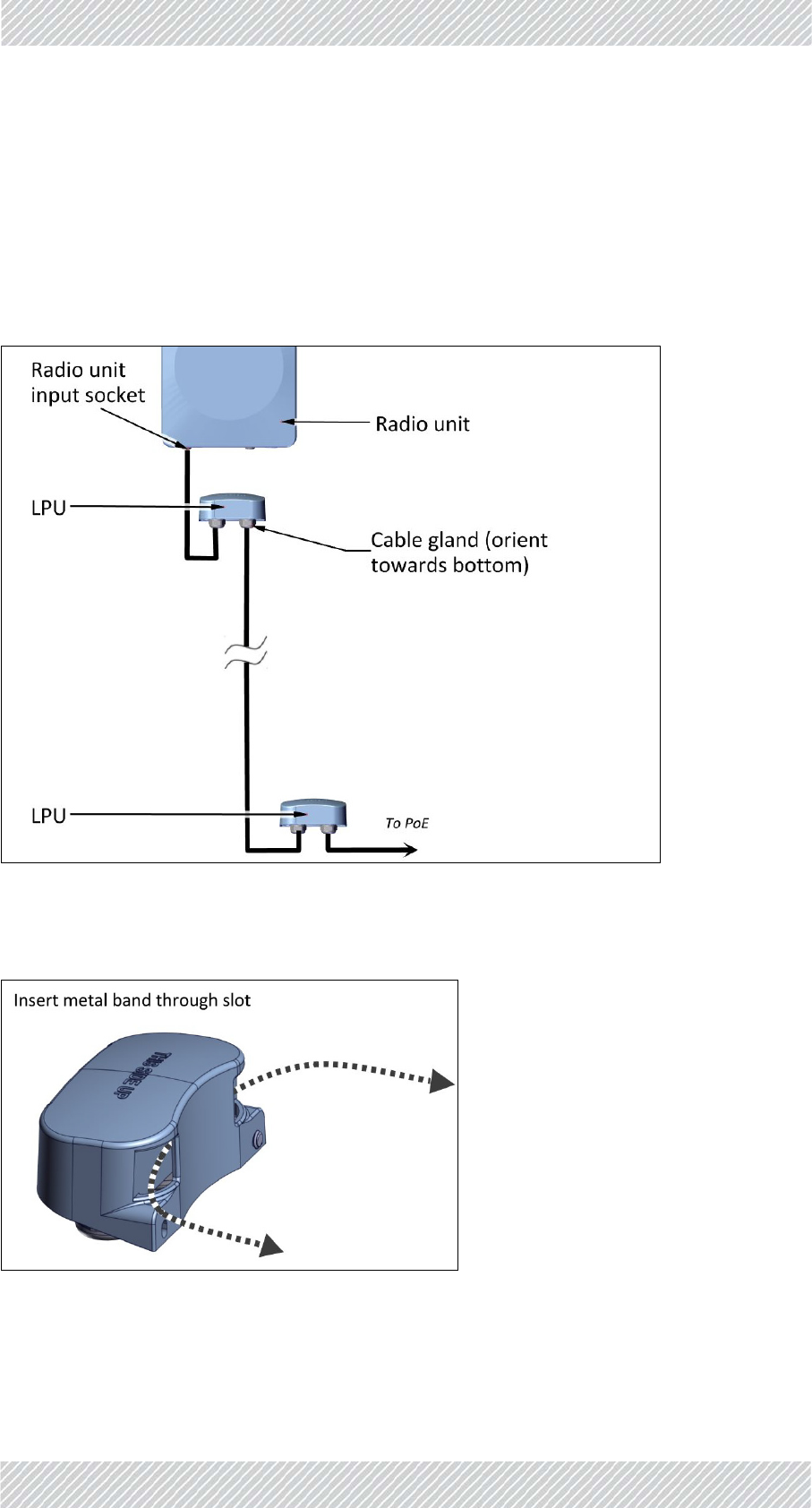
2.11MountingtheLightningProtectionUnits
•Werecommendusingtwolightningprotectionunits(LPUs)foreachradiounitinstalla‐
tion:OneneartheradiounitandonenearthePoE.
•TheLPUcanbemountedonapoleoronawall.
•MakesuretheLPUisorientedwiththecableglandsorientedtowardsthebottom.
•MountoneLPUneartheradiounit,andthesecondnearthePoE:
2.11.1MountingtheLPUonapole
1. InsertthemetalbandthroughtheslotsontheLPUasshown:
RADWIN5000InstallationGuide Release4.9.30 2‐28
MountingtheLPUonapole InstallationSteps
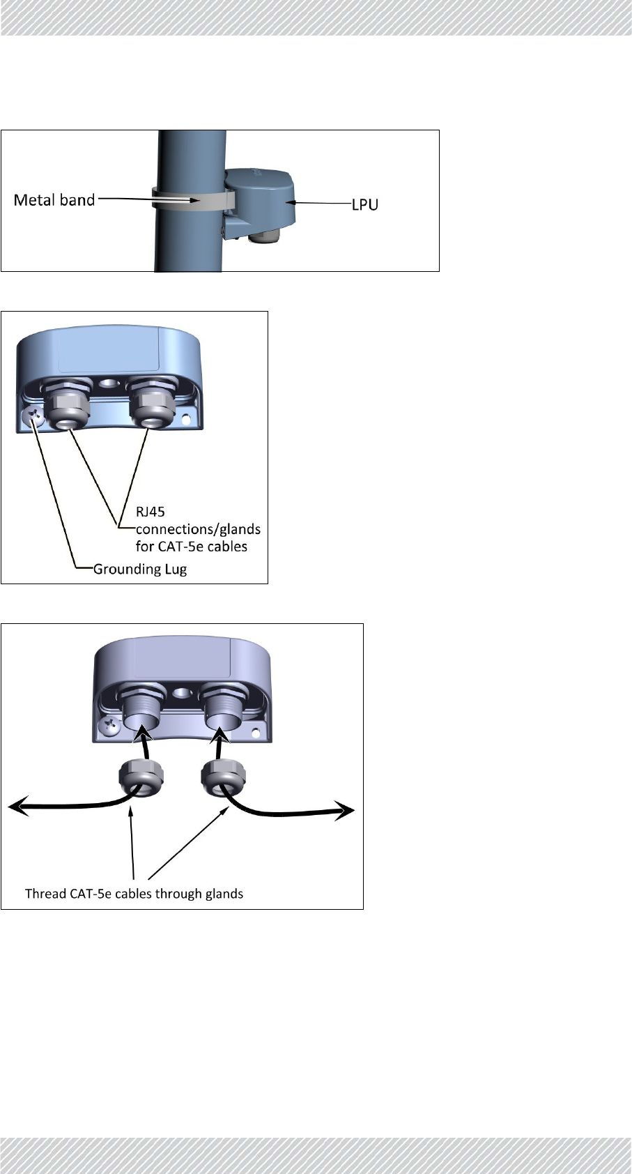
2. Tightenthemetalband.
3. Connectthegroundinglugtoagroundsource.
4. Removethecableglands,andthreadtheCAT‐5ecablesthroughthem:
RADWIN5000InstallationGuide Release4.9.30 2‐29
MountingtheLPUonawall InstallationSteps
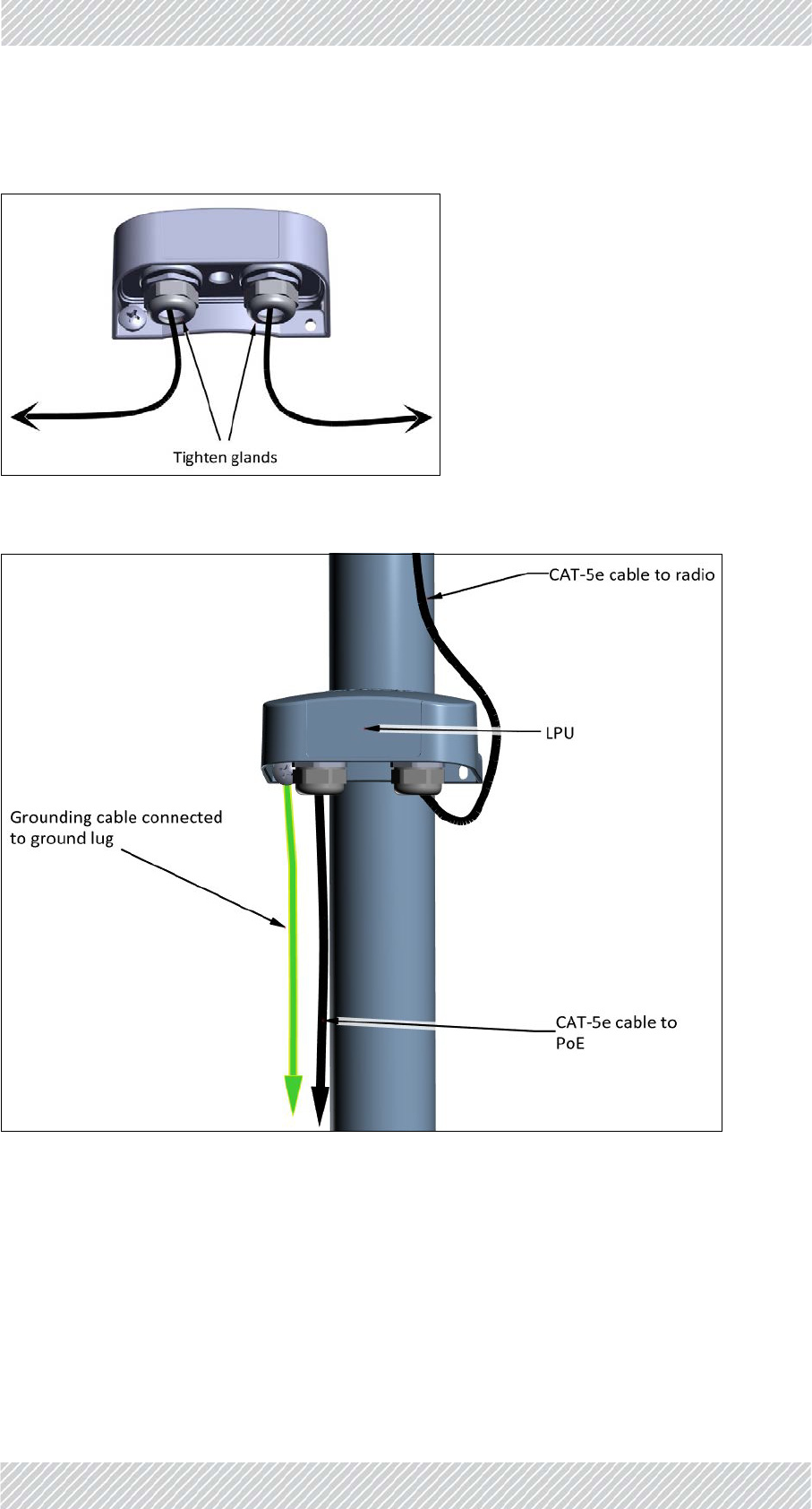
5. ConnectthecablestotheLPU’ssockets,andtheglandsaroundthecablesas
shown:
6. RouteoneCAT‐5ecableuptotheradiounit,andtheotherdowntothePoE(via
thelowerLPU).AnLPUinstalledonapoleisshownbelow:
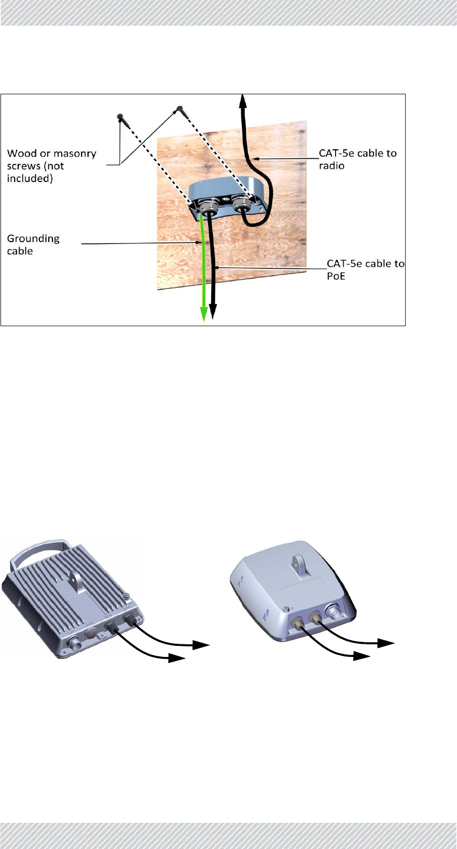
2.11.2MountingtheLPUonawall
1. Removethegroundinglug.
2. FastentheLPUtothewallusingscrewsappropriateforthewall(screwsnot
included).
3. Connecttheleftscrew(wherethegroundinglugwaslocated)toagrounding
sourceviaagroundingcable.
RADWIN5000InstallationGuide Release4.9.30 2‐30
ConnectExternalAntenna(ifapplicable) InstallationSteps
4. AttachtheCAT‐5ecablesasshowninSteps4.and5.above.
2.12ConnectExternalAntenna(ifapplicable)
Anexternalorsupplementalantennacanbeusedfortheseunits:
•ConnectorizedLFF(largeform‐factor)radiounits
•ConnectorizedSFF(smallform‐factor)radiounits
•SUPRO/AIRradiounits
2.12.1LFFandSFFUnits
Connecttheexternalantennatotheantennaconnectionsontheradioasshown.
Mounttheradiounitusingastandardmountingkit(seeMountingaUnitwiththeStandard
MountingKitonpage 2‐17),aswellastheexternalantenna(needsitsownmountingkit).
Toantenna Toantenna
RADWIN5000InstallationGuide Release4.9.30 2‐31
SUPRO/AIRUnits InstallationSteps
ItdoesnotmatteriftheVorHconnectionoftheantennaisconnectedtoeithertheANT1or
ANT2connectionoftheradio,butwhatisimportantisthatyoupreservethesame
connectionschemethroughoutthesector(eg:VisalwaysconnectedtoANT1,Hisalways
connectedtoANT2).
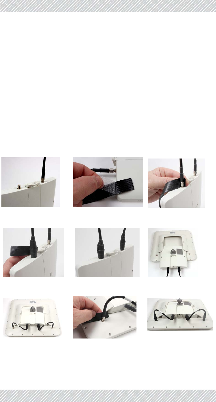
2.12.2SUPRO/AIRUnits
TurboGainantenna
FastentheTurboGainantennaontheSUPRO/AIRunitusingthesesteps::
a. Connectthecablestotheradio
b. Sealthecables(seeWaterproofingonpage 2‐32)
c. ConnecttheTurboGainantenna
d. ClosethescrewsoftheTurboGainantenna
e. SealtheconnectorsontheTurboGainantennausingthesealingtape.
Connectcables Preparesealingtape Applysealingtape‐1
Applysealingtape‐2 Sealingtapeapplied ConnectTurboGainantenna
ConnectcablestoTurboGain SealingtapeforTurboGain TapeappliedonTurboGain‐2
RADWIN5000InstallationGuide Release4.9.30 2‐32
Waterproofing InstallationSteps
External,non‐integratedantenna
Followthesestepstoconnectanexternal,non‐integratedtotheSUPRO/AIRunit:
a. Connectthecablestotheradio
b. SealthecablesusingScotchTM23splicingtapeorsimilar.
c. Mountanexternal,non‐integratedantennausingthestandardmountingkit(see
MountingaUnitwiththeStandardMountingKitonpage 2‐17).
d. Connectthecablestotheexternal,non‐integratedantenna
e. Sealtheconnectorsontheexternal,non‐integratedantenna(seeWaterproofingon
page 2‐32)
ItdoesnotmatteriftheVorHconnectionoftheantennaisconnectedtoeithertheANT1or
ANT2connectionoftheradio,butwhatisimportantisthatyoupreservethesame
connectionschemethroughoutthesector(eg:VisalwaysconnectedtoANT1,Hisalways
connectedtoANT2).
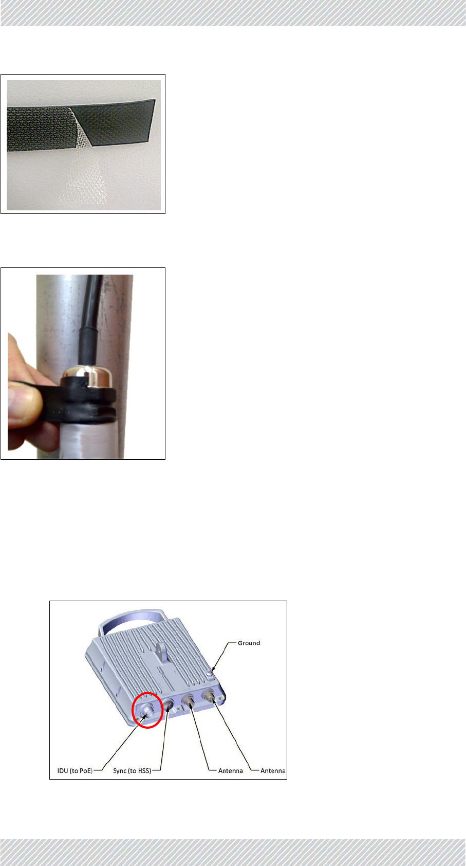
2.13Waterproofing
Protectalloutdoorconnections1fromrain,dust,moistureandsaltbytapingthecable/gland
connectionwithanappropriatesealanttape.WerecommendusingScotchTM23splicingtape
orsimilar.
Youmayneedtore‐aligntheunit.
Re‐configuretheunitashavinganexternalantenna(seetheRADWIN5000
ConfigurationGuide).
Youmayneedtore‐aligntheantenna.
1. ThisisnotrequiredfortheSUPRO/AIRunit
Toantenna
RADWIN5000InstallationGuide Release4.9.30 2‐33
ConnectRadio(ExternalConnections) InstallationSteps
Figure2‐39:Sealanttape
Addtapeasshownbelow.
Figure2‐40:Applyingsealanttapetoanexternalconnection
2.14ConnectRadio(ExternalConnections)
2.14.1LFF,SFFandJETUnits
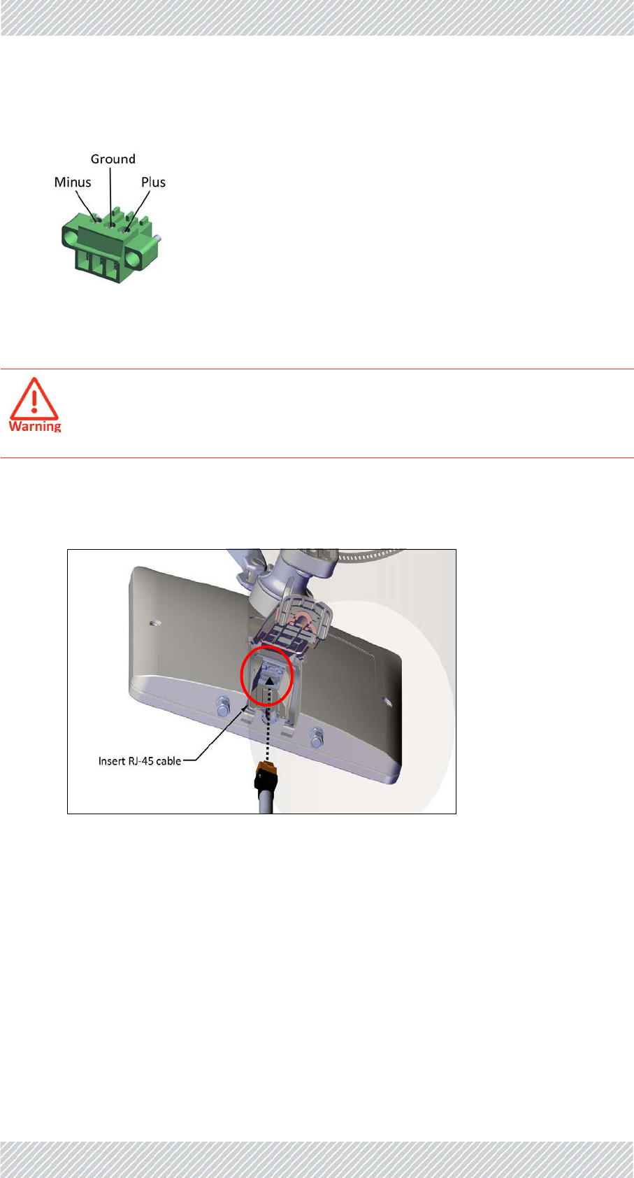
1. ConnectaCAT‐5ecabletotheinputportoftheradioasshown:
Figure2‐41:Inputport:LFFunit(connectionlabel:“IDU”)
RADWIN5000InstallationGuide Release4.9.30 2‐34
DUOUnits InstallationSteps
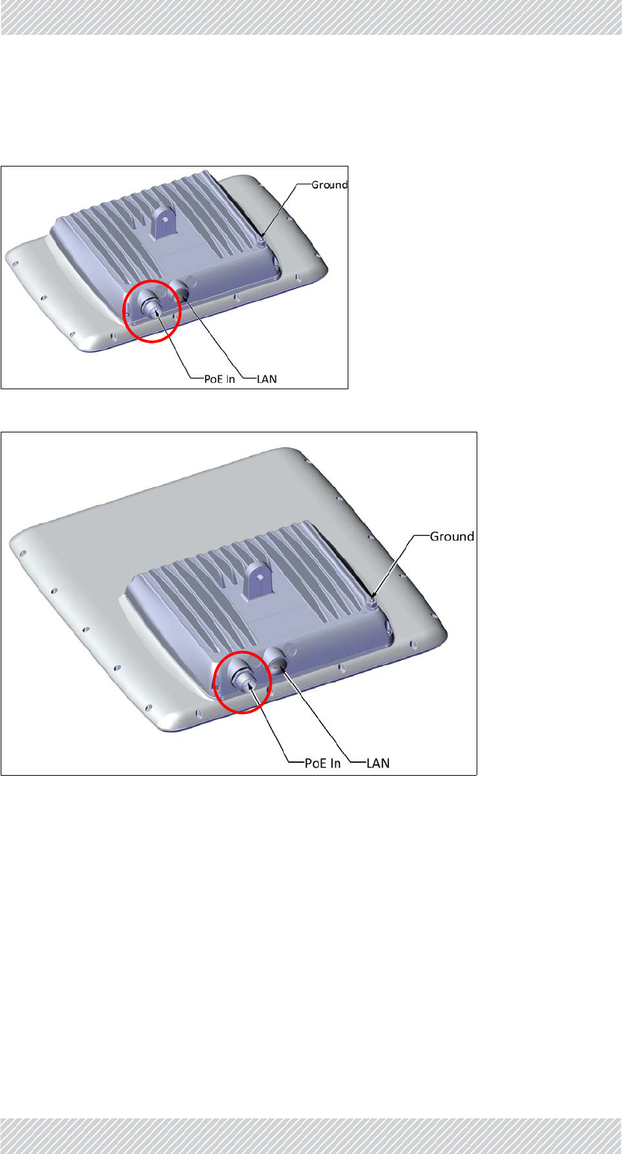
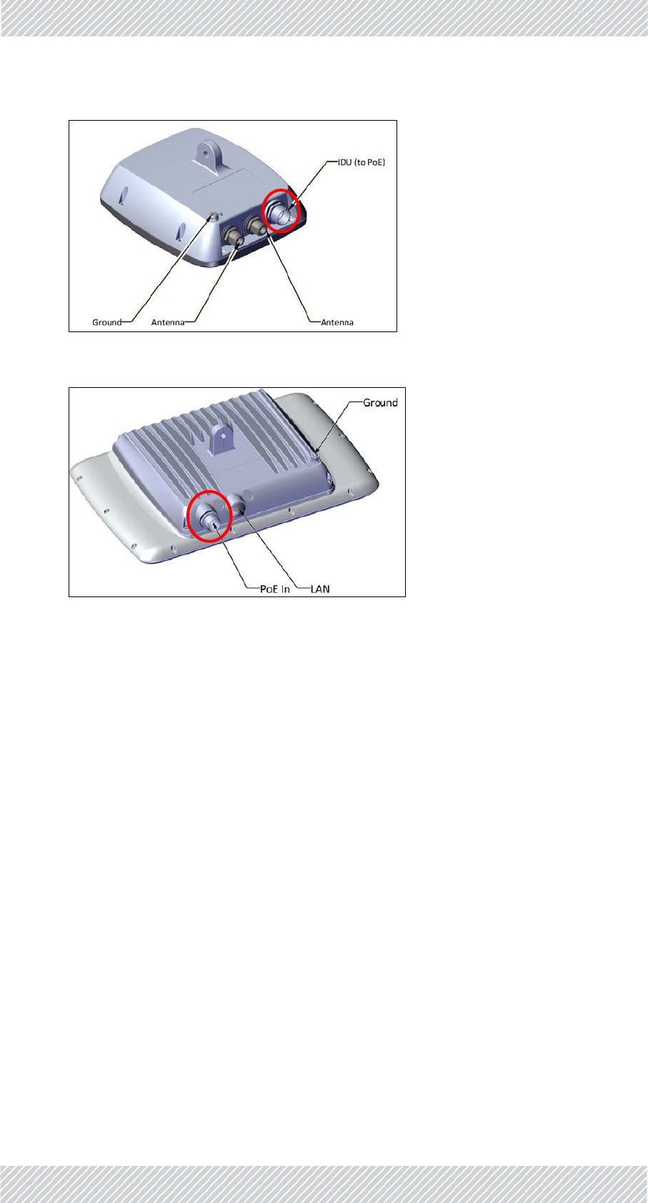
2.14.2DUOUnits
1. ConnectaCAT‐5ecabletothe“PoEIN”portoftheradioasshown.Thisconnection
providespowertotheunitandcanalsoserveasamanagementanddataconnection.Itis
referredtoas“LAN1”intheRADWINManagerapplication:
Figure2‐42:Inputport:SFFunit(connectionlabel:“IDU”)
Figure2‐43:Inputport:JETunit(connectionlabel:“PoEIn”)
RADWIN5000InstallationGuide Release4.9.30 2‐35
DUOUnits InstallationSteps
3. Addsealanttapetotheconnections(see"Waterproofing"onpage2‐32.)
Figure2‐44:Inputpoweranddataport:DUOunit(“PoEIN”=LAN1)
2. Alternatively,youcanusetheSFPconnection(labeled“LAN”),which
providesmanagementanddataconnectiononly(nopower).This
connectionisreferredtoas“LAN2”intheRADWINManager
application.NotethatyoumuststillconnectaCAT‐5ecableto“PoEIn”
toprovidepower:
Figure2‐45:Inputdataport:DUOunit(LAN=“LAN2”)
“LAN1”
“LAN2”
RADWIN5000InstallationGuide Release4.9.30 2‐36
DUOUnits InstallationSteps
4. RoutetheCAT‐5eandgroundcablesdownfromtheradiotoaPoEvia2LPUs:one
neartheradio,onenearthePoE.FastenCAT‐5ecableconnectionswithacable
gland,addsealanttape.
5. Connectgroundcabletoground.
6. PerformfinalconnectionsviaaPoE,dependingonthetypeofPoEyouareusing,
asfollows:
IndoorPoE
a. ConnectCAT‐5ecablefromlowerLPUto“Out”port
b. ConnectLANcableto“In”port.
c. Connectpowercable
OutdoorPoE
ConnectCAT‐5ecablefromlowerLPUto“Po E”port,fasten withgland,addtape.
a. ConnectLANcableto“ETH”port,fastenwithcablegland,addtape.
b. Connectgroundcable.
Ifyouusethe“LAN”portformanagementordata,itmustconfiguredproperly.
SeetheRADWIN5000ConfigurationGuideformoredetails.
RADWIN5000InstallationGuide Release4.9.30 2‐37
DUOUnits InstallationSteps
c. Connectpowercable
IDU‐H
(TheIDU‐Hdoesnotsupportthebeam‐formingHBS(JETorDUO).
TheIDU‐HisanaggregationswitchwiththefunctionalityofsixPoEdevices.Itisidealforuse
atabasestationhavingseveralcollocatedradios.
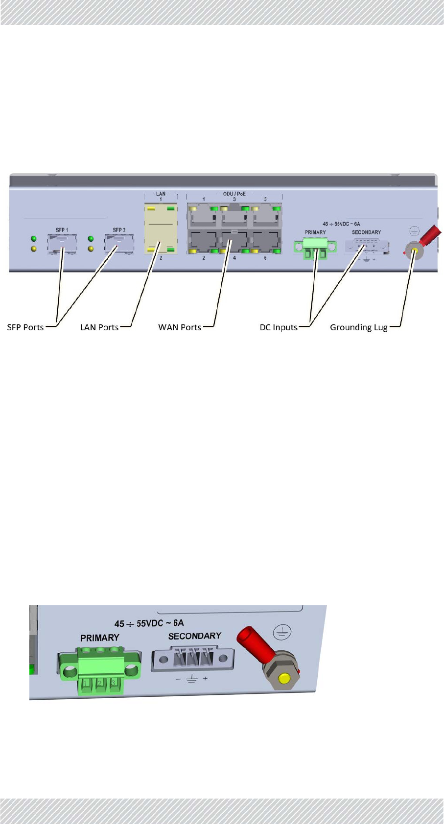
Figure2‐46:IDU‐H
TheIDU‐Hhasthefollowingconnections:
•SFPports
•LANports:Ethernet,supportingGbE.
•WANports:FunctionidenticallytotheLAN‐OutportonaPoEdevice.
•DCInputs
•Groundinglug
•LEDcolors:Green=link/activity,Yellow=Duplex/two‐waycommunication
InstallingtheIDU‐H:
•TheIDU‐Hcansitonatabletop,butisbestinstalledinarack.
•ConnecttheHBSIDUporttoanyofthesixPoEportsoftheIDU‐H.
•TheIDU‐HhastwoLANports,eitherofwhichmaybeusedfornetworkconnection.
•TheIDU‐Hhasredundantpowerconnectioncircuits.Aviewofthepowerconnectorsis
shownbelow.Inthiscase,onlytheprimarycircuithasapowerconnector:
Figure2‐47:IDU‐Hpowerconnectorsandgroundinglug.
RADWIN5000InstallationGuide Release4.9.30 2‐38
SUPRO/AIRUnits InstallationSteps
•FordirectDCconnection:Theconnectorsare3pininlinefemale,withpolarities(leftto
right)minus,ground,plus,asshown:
•ForACconnection:ToavoiddamagetotheIDU‐H,alwaysuseanAC/DCadapterand
powerplugsuppliedbyRADWIN.
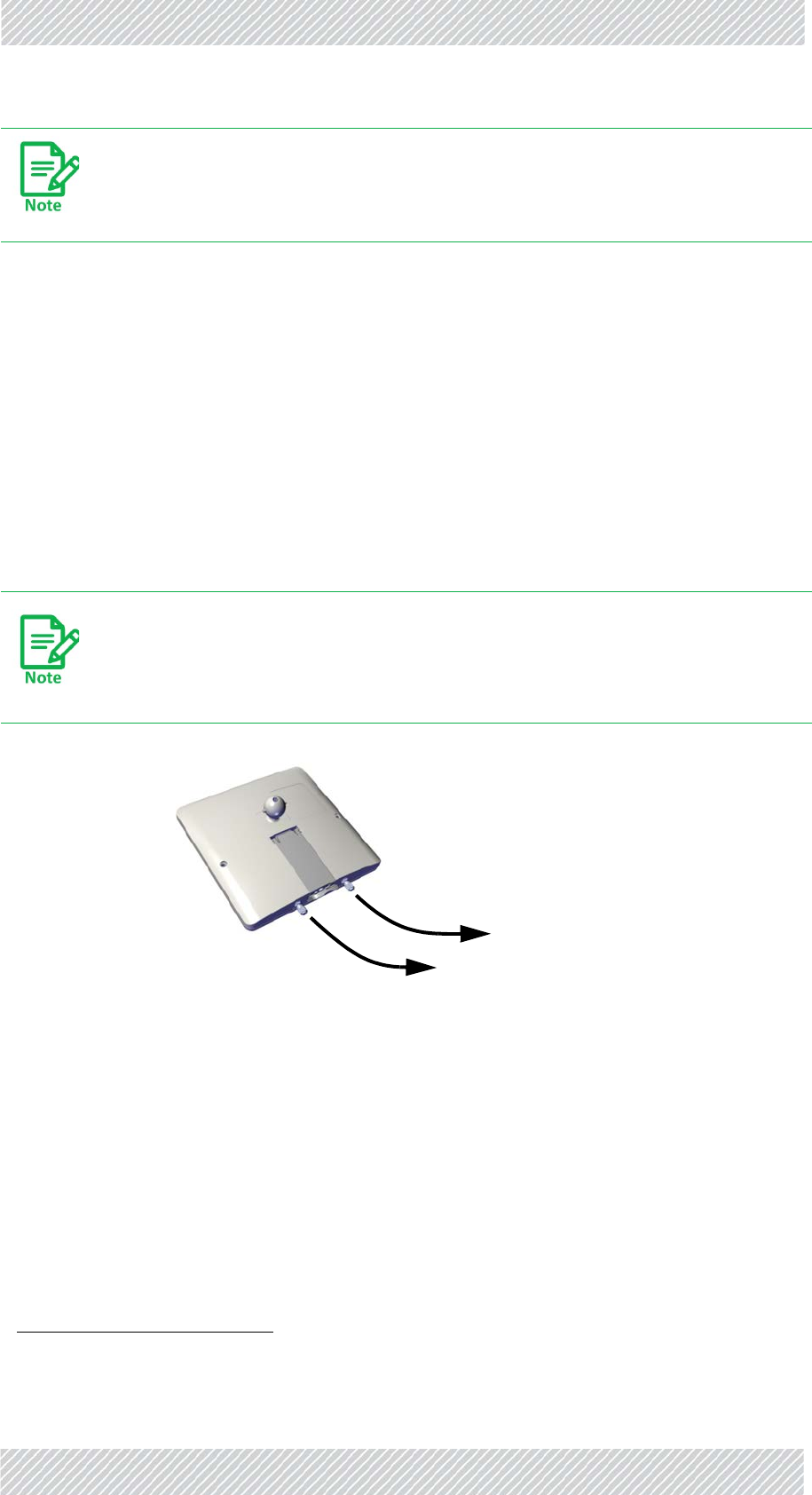
2.14.3SUPRO/AIRUnits
1. ConnectaCAT‐5ecabletotheinputportoftheradioasshown:
2. RoutetheCAT‐5eandgroundcablesdownfromtheradiotoaPoE.
•Recommended,althoughnotrequired:routetheCAT‐5ecablevia2LPUs:onenear
theradio,onenearthePoE.FastenCAT‐5ecableconnectionswithgland,addseal‐
anttape.
3. Connectgroundcabletoground.
4. PerformfinalconnectionsviatheSUPRO/AIRPoE:
Groundtheunitwitha10AWGwirebeforeapplyingpower.
Figure2‐48:Inputport:SUPRO/AIRunit
Connectionlabel:None
RADWIN5000InstallationGuide Release4.9.30 2‐39
CheckConnectivitytoRadio InstallationSteps
5. ConnectCAT‐5ecablefromlowerLPUtothe“PoE”port.
6. ConnectLANcableto“LAN”port.
7. Connectpowercable.
2.15CheckConnectivitytoRadio
1. Connecttoradiounit:
•Fromalaptopinthefield:DisconnectthePoEfromthecommunicationsnetwork
(LANconnection),andconnectthelaptop.
•FromtheNOC:KeepthePoEconnectedtotheLAN.
•YoucanusetheSFPconnectionoftheRADWINJETDUO(labeled“LAN”)forcom‐
municationsandmanagementpurposesonly.
2. Fromacommandline,pingradiousingradio’sIPaddress.
2.16ActivateBaseStation
Applicableonlyifyouareinstallingabasestation.
1. Connecttoradiounit:
•Fromalaptopinthefield:DisconnectthePoEfromthecommunicationsnetwork
(LANconnection),andconnectthelaptop.
•FromtheNOC:KeepthePoEconnectedtotheLAN.
•YoucanusetheSFPconnectionoftheRADWINJETDUO(labeled“LAN”)forcom‐
municationsandmanagementpurposesonly.
2. LogontotheRADWINManagerapplicationas“Installer”.
3. EnterIPaddressofBaseStation(HBS).
4. FrommainwindowoftheRADWINManagerapplication,clickActivate.
5. Followwizardinstructionstoactivateradio.
RADWIN5000InstallationGuide Release4.9.30 2‐40
AlignSubscriberUnit InstallationSteps
2.17AlignSubscriberUnit
•Makesurethesubscriberunit’sbasestationisactivated(checkwiththeNOC).
•Pointthesubscriberunit(oritsexternalantenna)inthegeneraldirectionofitsbasesta‐
tion.
•Continueaccordingtothetypeofunityouareusing:
2.17.1LFFandSFFUnits
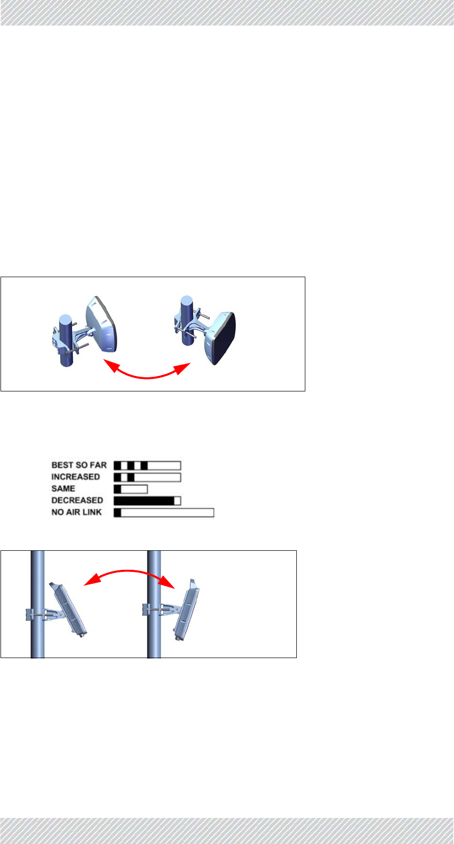
1. Aligntheunithorizontally(inazimuth):
a. Swiveltheunit90ototheleftslowly,180ototheright,andthen90obacktowards
thebasestation.
Figure2‐49:Swivelhorizontally(SFFunitshown)
b. Whileswivelingtheunit,listentothebuzzerbeepsequenceuntiloptimal
alignmentisachieved(3beepsandapause,asshownbelow).
2. Repeattheaboveinelevation.
Figure2‐50:Swivelvertically(LFFunitshown)
3. Oncealignmentiscomplete,tightentheboltholdingtheradioonthemounting
kit.
RADWIN5000InstallationGuide Release4.9.30 2‐41
SUPRO/AIRUnits InstallationSteps
•Thesubscriberunitwillstopbeepingwhenitisalignedwiththebasestation,andcon‐
figured.
•YoucanmanuallyceasethebeepingviatheRADWINManagerapplication.
2.17.2SUPRO/AIRUnits
1. ConnecttotheunitviaWiFiusingasmartphone.
2. UsingWINTouch:
•OperatetheWINTouchapplication,andfollowitsinstructions.
3. UsingtheWebInterface:
a. UsingaPCorlaptop:accessthewebinterface(entertheunit’sIPaddressinaweb
browser)
b. Loginusingusernameadminandpasswordnetman.
c. ActivatethedevicebyclickingTools‐>Operations‐>Functions‐>Device
Activation.
d. YoucancontinuewithaPCorasmartphone:ClickTools‐>AntennaAlignment.
RADWIN5000InstallationGuide Release4.9.30 2‐42
SUPRO/AIRUnits InstallationSteps
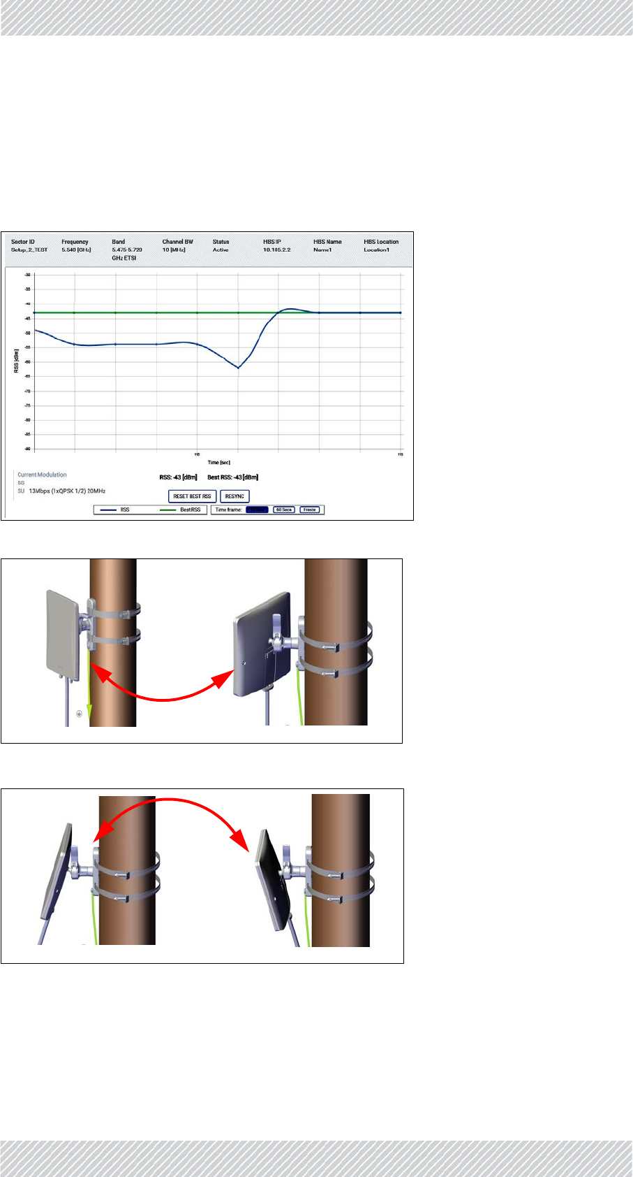
e. Agraphwillappearshowingthereal‐timeRSSvalueandthebestRSSvalueforthe
testperiod.Whilereferringtothereal‐timeRSSvalue,dothefollowing:
f. Swiveltheunitoritsexternalantenna90ototherightslowly,180ototheleft,and
then90obacktowardsthebasestation.NoteatwhichpointtheRSSvalueis
maximum.
g. Repeattheaboveinelevation.
Figure2‐51:Swivelhorizontally
Figure2‐52:Swivelvertically
RADWIN5000InstallationGuide Release4.9.30 2‐43
SUPRO/AIRUnits InstallationSteps
4. Oncealignmentiscomplete,tightenthearmonthemountingkit(seeFigure 2‐53
fortheSUPRO/AIR,seeFigure 2‐33foranexternalantenna).
5. Iftheunitrequiresmoretightening,usethehexscrewwitha5mmhexkeyas
showninFigure 2‐54.
Figure2‐53:Tightenarmonmount:SUPRO/AIRradiounit
Figure2‐54:Usehexscrewtofurthertightenarmonmount:SUPRO/AIRradiounit

RADWIN5000InstallationGuide Release4.9.30 3‐1
Chapter3:SafetyPracticesand
Provisions
3.1ScopeofthisChapter
Thischapterdescribesvarioussafetypractices.
3.1.1PreventingOverexposuretoRFEnergy
ToprotectagainstoverexposuretoRFenergy,installtheradiounitssoastoprovideand
maintainminimalseparationdistancesfromallpersons.
Whenthesystemisoperational,avoidstandingdirectlyinfrontoftheantenna.StrongRF
fieldsarepresentwhenthetransmitterison.Theradiounitmustnotbedeployedina
locationwhereitispossibleforpeopletostandorwalkinadvertentlyinfrontoftheantenna.
3.1.2Grounding
AllRADWINproductsshouldbegroundedduringoperation.Inaddition:
•AllODUsshouldbegroundedbyawirewithdiameterofatleast10AWG.
•ThegroundlugonanIDU‐Hshouldbeconnectedtotheprotectiveearthatalltimes,by
awirewithadiameterof18AWGorwider.
•Rack‐mountedequipmentshouldbemountedonlyingroundedracksandcabinets.
Further,youshould‐
•Alwaysmakethegroundconnectionfirstanddisconnectitlast
•Neverconnecttelecommunicationcablestoungroundedequipment
•Ensurethatallothercablesaredisconnectedbeforedisconnectingtheground
3.1.3ProtectionagainstLightning
Theuseoflightningprotectionisdependentonregulatoryandenduserrequirements.All
RADWINoutdoorunitsaredesignedwithsurgelimitingcircuitstominimizetheriskof

RADWIN5000InstallationGuide Release4.9.30 3‐2
General SafetyPracticesandProvisions
damageduetolightningstrikes.RADWINrecommendstheuseofadditionalsurgearrestor
devicestoprotecttheequipmentfromnearbylightningstrikes.
3.1.4General
•Itisrecommendedthatinstallationofoutdoorunitsbecontractedtoaprofessional
installer
•Beforeworkingonequipmentconnectedtopowerlinesortelecommunicationlines,
removejewelryoranyothermetallicobjectthatmaycomeintocontactwithenergized
parts
•Useextremecarewheninstallingantennasnearpowerlines
•Useextremecarewhenworkingatheights
•WhenusinganACpowersourceforRADWINdevices,alwaysusetheACpoweradapter
suppliedbyRADWIN
•Usetherighttools!
•Donotmountanradiounitupsidedownorhorizontally.Doingthismayvoidyouprod‐
uctwarranty.
3.1.5InternalESDProtectioncircuits
RADWINequipmentisdesignedtomeettheETSI/FCC/Aus/NZ/CSAEMCandSafety
requirements.Tofulfilltheserequirements,thesystem'sTelecomlinesattheradiounit/PoE
areTransformer‐isolatedandincludeinternalESD(Electro‐Static‐Discharge)Protection
circuits.
WheninstallinganACpoweredHSU:TomaintainOvervoltage
(Installation)CategoryII,installasuitablesurgesuppressordeviceinthe
branchcircuittolimitexpectedtransientstoOvervoltageCategoryII
values.
ThelimitsarebasedonIEC60664andarealsolocatedinTable2Hof
UL60950(formains<=150V,thetransientratingis1500V;for150V<
mains<=300V,thetransientratingis2500V;andfor300V<mains<=
600V,thetransientratingis4000V).

RADWIN5000InstallationGuide Release4.9.30 A‐1
AppendixA:Terminology
TableA‐1:Terminology(Sheet1of3)
Term Description
Assuredthroughput Actualnumberoftimeslotsallocatedtoaradiounit.
ACS
AutomaticChannelSelection.Optionthatinstructstheradioto
choosewhichfrequencytouse.Enablingordisablingthisoption
hasvariousramificationsasshowninthedocumentation.
ATPC AutomaticTransmitPowerControl
BE
BestEffort:Alevelofpriorityfortrafficinwhichusersreceive
dynamicresourceallocationaccordingtooveralldemand.They
arenotguaranteedresources.SeealsoCIR.
BS BaseStation:aradiothatcantransmitandreceivetomorethan
onepoint.SeealsoHBS
CIR
CommittedInformationRate:Alevelofpriorityfortrafficinwhich
usersreceiveaguaranteedpercentageofresourcesinadditionto
dynamicresourcesifavailable.SeealsoBE.
CPE CustomerPremisesEquipment
DBA
DynamicBandwidthAllocation:amethodthatallocates
bandwidthbetweenthevarioususersofthatsamebandwidthin
thenetwork.
DHCP
DynamicHostConfigurationProtocol:aprotocolthat
automaticallyassignsIPaddressesandothernetwork
configurationparameters.
Diversity
Atechniquebywhichthereliabilityofaradiolinkisincreased
usingmultipletransmittingandreceivingantennas,transmitting
thesamesignalonallantennas.
Downlink DatatrafficfromanHBStoanHSU,or
DatatrafficfromanRT‐AtoanRT‐B
DUO DualBandbasestation

RADWIN5000InstallationGuide Release4.9.30 A‐2
EIRP
Equivalent(orEffective)IsotropicallyRadiatedPower:Thepower
thatanantennamustemittoproducethepeakpowerdensityin
thedirectionofmaximumantennagain.Inourcases,thisis
usually:SystemTxPower+Antenna
Gain‐CableLoss.
FAA FederalAviationAdministration.AU.S.federalofficethatmanages
aviationregulationsthroughouttheUnitedStates.
Fixed(HSU) A“fixed”HSUremainsinonelocation,ascontrastedwitha
nomadicormobileHSU,whichdoesnotremaininonelocation.
GHSS GPSHubSiteSynchronization
HBS HighcapacityBaseStation.SameasaBS
HMU HighcapacityMobility(subscriber)Unit.SimilartoanHSU,butcan
bemobile.
HSC
HubSyncClient:WhenusingHubSiteSynchronization,oneunitis
amaster(generatesthesyncpulses),andtheotherunitsare
clients.
HSM
HubSyncMaster:WhenusingHubSiteSynchronization,oneunit
isamaster(generatesthesyncpulses),andtheotherunitsare
clients.
HSU HighcapacitySubscriberUnit.SameasanSU
ISU IntegratedSynchronizationUnit:anetworkdevicethatprovidesa
synchronizationsignaltoundergroundHBSs.
ITHO Intra‐trainhandovermechanism
LFF LargeForm‐Factor
MIMO
MultipleIn,MultipleOut.Atechniquebywhichthecapacityofa
radiolinkisincreasedusingmultipletransmittingandreceiving
antennas,transmittingadifferentsignalonallantennas.
MIR MaximumInformationRate
Mobile(HSU) A“mobile”HSUcanmovefromlocationtolocationandprovide
servicewhileitmovesorwhenitisstationary.
Nomadic(HSU) A“nomadic”HSUmovefromlocationtolocationbutcanonly
provideservicewhenitisstationary.
ODU OutdoorUnit:agenerictermforanyradio,andcanusuallybe
exchangedforHBSorHSU.
PtMP PointtoMulti‐Point:linkfromanHBStoseveralHSUs
PtP PointtoPoint
RADIUS RemoteAuthenticationDial‐InUserService
TableA‐1:Terminology(Sheet2of3)
Term Description

RADWIN5000InstallationGuide Release4.9.30 A‐3
QoS QualityofService
SBM SmartBandwidthManagement
Sector AgroupofradiosthatconsistsofoneHBSandseveralHSUsthat
communicatewiththeHBS.
SFF SmallForm‐Factor
SLA ServiceLevelAgreement
SSM
SynchronizationStatusMessage:Providestraceabilityof
synchronizationsignals,andisusedintheSynchronousEthernet
standardofcommunication.
SU SubscriberUnit:aradiothatcantransmitandreceivetoonepoint.
SeealsoHSU
SyncEorSyncE
SynchronousEthernet:Astandardofcommunicationforethernet
thatprovidesasynchronizationsignaltonetworkelementsthat
needsuchasignal.
TBS TransportationBaseStation.SimilartoanHBSorBS,butusedwith
high‐speedtransportationapplications.
TDWR
TerminalDopplerWeatherRadar:atypeofradarstationusedin
theU.S.andothercountriesforweatherreporting.Ifaradiounitis
installedcloseenoughtooneofthesestations,theFCCrequires
thatcertainactionsmustbetakenonthepartofthecustomer.
Regulationsinothercountriesvaries.
TMU TransportationMobileUnit.SimilartoanSU
TrackSide Itemsorsubjectmatterthatrelatestotheenvironmentnotonor
insidethetrain.Itisnotlimitedtopreciselynexttothetrack.
TrainSide Itemsorsubjectmatterthatrelatestotheenvironmentonor
insidethetrainitself.
Uplink DatatrafficfromanHSUtoanHBS,or
DatatrafficfromanRT‐BtoanRT‐A
VMUVehicularMobileUnit
WI WebInterface:web‐basedapplicationthatprovidessimple
configurationcapabilitiesfortheradiounits.
WISPA
WirelessInternetServiceProviderAssociation.Anorganization
thatmanagesregistrationofwirelessdevicesthatoperatecloseto
TDWRfacilitiesrunbytheFAA.
TableA‐1:Terminology(Sheet3of3)
Term Description

RADWIN5000InstallationGuide Release4.9.30 B‐1
AppendixB:Wiring
Specifications
B.1ScopeofthisAppendix
ThisappendixshowswiringspecificationsfortheHBSandHSU.
B.1Radiounit‐PoECable(HBSandHSU)
Theradiounit‐PoEcableisshielded/outdoorclassCAT‐5e,4twisted‐pair24AWGterminated
withRJ‐45connectorsonbothends.Acableglandontheradiounitsideprovideshermetic
sealing.
Thefollowingtableshowstheconnectorpinout:
TableB‐1:Radiounit‐PoERJ‐45ConnectorPinout
Function Color PoE ODU
RxNWhite/Green 1 1
RxTGreen 2 2
TxTWhite/Orange 3 3
TxNOrange 6 6
Power(+) Blue 4 4
Power(+) White/Blue 5 5
Power()White/Brown 7 7
Power()Brown 8 8

RADWIN5000InstallationGuide Release4.9.30 B‐2
ScopeofthisAppendix
B.2UserPortConnectors
B.2.1LANPort
TheLAN10/100BaseTinterfaceterminatesinan8‐pinRJ‐45connector,wiredinaccordance
toTable B‐3.
B.3DCPowerTerminals
B.3.1DCPoE
DCpowerterminalsareasfollows:
TableB‐2:LAN‐GbEPoERJ‐45ConnectorPinout
Function Color PoE LAN
TxRxAWhite/Green 1 1
TxRxAGreen 2 2
TxRxBWhite/Orange 3 3
TxRxBOrange 6 6
TxRxC&Power(+) Blue 4 4
TxRxC&Power(+) White/Blue 5 5
TxRxD&Power(‐)White/Brown 7 7
TxRxD&Power(‐)Brown 8 8
TableB‐3:FastEthernetConnectorPinout
Function Signal Pin
TransmitData(positive) TD(+) 1
TransmitData(negative) TD(–) 2
ReceiveData(positive) RD(+) 3
ReceiveData(negative) RD(–) 6
TableB‐4:TerminalBlock2‐pin‐48VDC
Function Pin
+Right
–Left

RADWIN5000InstallationGuide Release4.9.30 B‐3
ScopeofthisAppendix
B.4SU2‐ACPowerTerminal
TheSU2‐ACpowerportisafourpinmalesocketwithpinassignmentsasfollows:
TableB‐5:SU2‐ACpowerpinassignments
PinWireColor Function
1Red Line
2Notused
3 Black Neutral
4GreenorGreen‐
Yellow Ground

RADWIN5000InstallationGuide Release4.9.30 C‐1
AppendixC:AboutAntennas
C.1ScopeofthisAppendix
Thisappendixprovidessomebasicinformationandconsiderationsregardingantennasand
whatyouneedtotakeintoaccountwhenconfiguringantennaparameters.
C.1AntennaIssues
ThechoiceofTxPower,antennagainandcableloss(betweentheradioandtheantenna)
determinestheEIRPandisaffectedbysuchconsiderationsasradiolimitationsandregulatory
restrictions.
Beforeproceedingtoantennainstallationdetails,thefollowingbackgroundinformation
shouldbeconsidered:
C.2AboutSingleandDualAntennas
EachRADWIN5000HPMPODUismadeoftworadiotransceivers(radios).Theradiosmake
useofalgorithmsthatutilizebothSpatialMultiplexing(alsocalledMIMO)andDiversity
resultinginenhancedcapacity,rangeandlinkavailability.Thenumberofantennas(i.e.
radios)usedisdeterminedbyuserconfigurationandbyautomaticsystemdecisions,
explainedbelow.
C.2.1DualAntennasattheHBSandanHSU
Whenusingdualantennasatbothsites(singlebipolarantennaortwomo‐unipolarantennas)
youcanchoosebetweenSpatialMultiplexingModeandDiversityMode.
SpatialMultiplexingMode
Underthismode,thesystemdoublesthelinkcapacity.Atthesametime,itkeepsthesame
rateandmodulationperradioaswasusedwithsingleantenna,thusincreasingcapacity,
rangeandavailability.

RADWIN5000InstallationGuide Release4.9.30 C‐2
ScopeofthisAppendix
ForexamplewithadualantennaRADWIN5000HPMPcantransmitatmodulationof64QAM
andFECof5/6andgetanairrateof130Mbps,comparedto65Mbpswithsingleantenna.
Toworkinthismode,eachantennaportmustbeconnectedtoanantenna,theRSSlevelin
bothreceiversshouldbebalancedandaminimalseparationbetweentheantennasmustbe
maintained.(Forexample,byusingdualpolarizationantennasacrosspolarizationseparation
isattained).
UponselectingAntennaTypeasDual,RADWIN5000HPMPautomaticallyselectsthismode
anddoublestheairrates.
RADWINManagerindicatesacaseofunbalancedRSSbetweenthetwoantennasintheHBS
panels.
DiversityMode
DiversityModeusestwoantennastoimprovethequalityandreliabilityofthelink.Often,
thereisnotaclearline‐of‐sight(LOS)betweentransmitterandreceiver.Insteadthesignalis
reflectedalongmultiplepathsbeforefinallybeingreceived.
Eachsuch“bounce”canintroducephaseshifts,timedelays,attenuations,andeven
distortionsthatcandestructivelyinterferewithoneanotherattheapertureofthereceiving
antenna.Antennadiversityisespeciallyeffectiveatmitigatingthesemulti‐pathsituations.
Thisisbecausemultipleantennasaffordareceiverseveralrecordingsofthesamesignal.Each
antennawillbeexposedtoadifferentinterferenceenvironment.Thus,ifoneantennais
undergoingadeepfade,itislikelythatanotherhasasufficientsignal.Collectivelysucha
systemcanprovidearobustlink.
Antennadiversityrequiresantennaseparationwhichispossiblebyusingadual‐polarization
antennaorbytwospatiallyseparatedantennas.
UseDiversityinsteadofSpatialMultiplexinginthefollowingsituations:
•WhenthesystemcannotoperateinSpatialMultiplexingMode
•Whenoneofthereceivershashighinterferencecomparedtothesecondreceiver(i.e.
thesystemis“unbalanced”)
•WhenyouachievehighercapacityinDiversityModethaninSpatialMultiplexingMode
•WhenhighrobustnessisofimportanceandthecapacityofDiversityModeissufficient
(upto25Mbpsfullduplex)
C.2.2SingleAntennasatBothSites
ByselectingasingleantennaattheHBSandHSU,theODUsoperatewithasingleradiothatis
connectedtotheANT1connector.Thesecondradioisautomaticallyshutdown.
C.2.3SingleatOneSite,DualAntennasattheOther
InthismodeoneofthesitesusestheODUwithasingleantennawhiletheothersiteusesthe
ODUwithadualantenna.

RADWIN5000InstallationGuide Release4.9.30 C‐3
ScopeofthisAppendix
Theadvantagesinthismodeincomparisontousingasingleantennainbothsitesare
doubledtotalTxPowerandadditionalpolarizationand/orspacediversity(dependingonthe
polarizationofinstalledantennas).
Theairratesusedinthismodearesameaswhenusingsingleantennasinbothsites.
Table C‐1summarizesthesituation:(SM=SpatialMultiplexing)
SiteAandBmaybeHBSorHSU.
C.3ConsiderationsforChangingAntenna
Parameters
Let:
maxAvailableTxPowerdenotethemaximumTxPowerpracticallyavailablefromanODU.(It
appearsasTxPowerperRadio.)
maxRegEIRPdenotethemaximumEIRPavailablebyregulation.Itwillbedeterminedby
threefactors:
•perband/regulation
•perchannelbandwidth
•antennagain
maxRegTxPowerdenotethemaximumregulatoryTxPowerfortheequipment,alsohaving
regardtheabovethreepoints.
Then,thefollowingrelationshipmustbesatisfied:
...(*)
TheTxPower(perradio)indicatesthepowerofeachradioinsidetheODUandisusedforLink
BudgetCalculations.TheTxPower(System)showsthetotaltransmissionpoweroftheODU
andisusedtocalculatetheEIRPaccordingtoregulations.
TableC‐1:SpatialMultiplexing‐Diversitysettings
Numberof
Antennas Mode MaxFull
Duplex
Capacity
SiteASiteBSiteASiteB
2 2
Spatial
Multiplexing
Spatial
Multiplexing 50Mbps
Diversity Diversity 25Mbps
2 1 Diversity Single 25Mbps
1 2 Single Diversity 25Mbps
1 1 Single Single 25Mbps
maxAvailableTxPower min maxRegEIRP
AntennaGain CableLoss maxRegTxPower+– ()

RADWIN5000InstallationGuide Release4.9.30 C‐4
ScopeofthisAppendix
Theinequality(*)aboveisalwayssatisfiedbythesysteminaccordancewiththerelevant
regulation.
Thepreciserelationshipbetweentheitemsininequality(*)isasfollows:
•RequiredTxPower(perradio)willbeadjusteddowntothelesserofthevalueentered
andmaxAvailableTxPower
•TxPower(system)ismaxAvailableTxPower+3(for2radios)
•MaxEIRPismaxRegEIRP.
•EIRPismaxAvailableTxPower+AntennaGain‐CableLoss
•TheMaxEIRPlevelwillbeautomaticallysetaccordingtothe
selectedbandandregulation.

RADWIN5000InstallationGuide Release4.9.30 D‐1
AppendixD:RegionalNotice:
FrenchCanadian
D.1Procéduresdesécurité
D.1.1Généralités
Avantdemanipulerdumatérielconnectéàdeslignesélectriquesoudetélécommunications,
ilestconseillédesedéfairedebijouxoudetoutautreobjetmétalliquequipourraitentreren
contactaveclesélémentssoustension.
D.1.2Miseàlaterre
TouslesproduitsRADWINdoiventêtremisàlaterrependantl'usagecourant.Lamiseàla
terreestassuréeenreliantlafiched'alimentationàuneprisedecourantavecuneprotection
deterre.Enoutre:
•Lacossedemassesurl'IDU‐Cdoitêtreconstammentconnectéeàlaprotectionde
terre,paruncâbledediamètrede18AWGouplus.Lematérielmontésurrackdoitêtre
installéseulementsurdesracksouarmoiresreliésàlaterre
•UneODUdoitmiseàlaterreparuncâbledediamètrede10AWGouplus
•Ilnedoitpasyavoirdefusiblesoud'interrupteurssurlaconnectionàlaterre
Deplus:
•Ilfauttoujoursconnecterlaterreenpremieretladéconnecterendernier
•Ilnefautjamaisconnecterlescâblesdetélécommunicationàdumatérielnonàlaterre
•Ilfauts'assurerquetouslesautrescâblessontdéconnectésavantdedéconnecterla
terre
D.1.3Protectioncontrelafoudre
L'utilisationdedispositifsdeprotectioncontrelafoudredépenddesexigences
réglementairesetdel'utilisateurfinal.TouteslesunitésextérieuresRADWINsontconçues
avecdescircuitsdelimitationdesurtensionafindeminimiserlesrisquesdedommagesdusà

RADWIN5000InstallationGuide Release4.9.30 D‐2
lafoudre.RADWINconseillel'utilisationd'undispositifdeparafoudresupplémentaireafinde
protégerlematérieldecoupsdefoudreproches.
Matérielsupplémentairerequis
L'équipementrequispourl'installationdumatérielestlesuivant:
•PinceàsertirRJ‐45(siuncâblepré‐assembléODU/IDUn'estpasutilisé)
•Perceuse(pourlemontagesurmurseulement)
•CâblesdeterreIDUetODU
•Clef13mm(½)
•CâbleODU‐IDUsinoncommandé(typeextérieur,CAT‐5e,4pairestorsadées,24AWG)
•Colliersdeserrage
•OrdinateurportableavecWindows2000ouWindowsXP.
D.1.4PrécautionsdesécuritépendantlemontagedeODU
Avantdeconnecteruncâbleàl'ODU,laborneprotectricedemasse(visse)del'ODUdoitêtre
connectéeàunconducteurexterneprotecteurouàunpylônereliéàlaterre.Ilnedoitpasy
avoirdefusiblesoud'interrupteurssurlaconnectionàlaterre.
Seulementunpersonnelqualifiéutilisantl'équipementdesécuritéappropriédoitpouvoir
montersurlepylôned'antenne.Demême,l'installationouledémontagedeODUoude
pylônesdoitêtreeffectuéeseulementpardesprofessionnelsayantsuiviuneformation.
Pourmonterl'ODU:
1.Vérifierquelessupportsdefixationdel'ODUsontcorrectementmisàlaterre.
2. Monterl'unitéODUsurlepylôneousurlemur;seréféreràlaInstallationsur
pylôneetmuraudessous.
3. Connecterlacâbledeterreaupointdechâssissurl'ODU.
4. RelierlecâbleODU‐IDUauconnecteurODURJ‐45.
5. Visserlespresses‐étoupedecâblespourassurerlescellementhermétiquedes
unitésODU.
6. AttacherlecâbleaupylôneouauxsupportsenutilisantdescolliersclassésUV.
7. Répéterlaprocéduresurlesitedistant.
D.1.5ConnecterlaterreàIDU‐C
Connecteruncâbledeterrede18AWGàlabornedemassedel'appareil.L'appareildoitêtre
constammentconnectéàlaterre.
Nepasseplacerenfaced'uneODUsoustension.
RADWIN5000InstallationGuide Release4.9.30 D‐3
D.2Installationsurpylôneetmur
L'ODUoul'O‐PoEpeuventêtremontéssurunpylôneouunmur.
D.2.1ContenudukitdemontageODU
LekitdemontageODUcomprendlespiècessuivantes:
FigureD‐1:ContenudukitdemontageODU
•Lesappareilssontprévuspourêtreinstallésparunpersonneldeser‐
vice.
•Lesappareilsdoiventêtreconnectésàuneprisedecourantavecune
protectiondeterre.
•LecourantCCduIDU‐Cdoitêtrefourniparl'intermédiaired'undisjonc‐
teurbipolaireetlediamètreducâbledoitêtrede14mmavecuncon‐
duitde16mm.
RADWIN5000InstallationGuide Release4.9.30 D‐4
D.2.2Montagesurunpylône
D.2.3Montagesurunmur
D.2.4Montaged'uneantenneexterne
L'antenneexterneoptionnellepeutêtremontéesurunpylône.
D.2.5Contenudukitdemontaged'uneantenneexterne
Lekitdemontaged'uneantenneexternecomprendlespiècessuivantes
•Douzerondellesplates
•Huitrondellesélastiques
•Huitécroushex
FigureD‐2:Montagesurunpylône(1) FigureD‐3:Montagesurunpylône(2)
FigureD‐4:Montagesurunmur(1) FigureD‐5:Montagesurunmur(2)

RADWIN5000InstallationGuide Release4.9.30 D‐5
•Quatreboulons
•UnsupportenU
•Unsupportàpivotement
•Deuxcourroiesdefixationenmétal
Pourinstalleruneantenneexternesurunpylône:
1.AttacherlesupportenUàl'arrièredel'antenneenutilisantquatrerondellesplates,
quatrerondellesélastiquesetquatreécroushex.
2. AttacherlesupportàpivotementausupportenUenutilisanthuitrondellesplates,
quatrerondellesélastiques,quatreécroushexetquatreboulons.
3. Passerlesdeuxcourroiesdefixationparlesfentesverticalesdanslesupportà
pivotement.
4. Attacherl'antenneaupylôneenutilisantlesdeuxcourroiesdefixation.
Ajusterl'inclinaisonnécessaireenutilisantl'échelleangulaireetserrertouslesboulonset
écrousàlapositionrequise.

RADWIN5000InstallationGuide Release4.9.30 E‐1
AppendixE:CertifiedAntennas
E.1ForDeploymentinUS/Canada
RadiodevicesthatbearthefollowingFCC/ICIDsrefertoTable E‐1toTable E‐4below:
ContainsFCCID:Q3K‐5XACMOLD
ContainsIC:5100A‐5XACMOD
Onlytheantennasshowninthetablesbeloworantennasofthesametypewithlowergain
areapprovedforuseinthissystem.Theantennasmustbeinstalledsoastoprovidea
minimumseparationdistancefrombystandersasspecifiedinthetablesbelow:
TableE‐1:FrequencyBand5725‐5850MHz
Cat.No. Type Gain(dBi) Dir
BW
TxPower
perchain
(dBm)
Min.Safe
Distance(cm)
Integrated FlatDPBS 11.0 120° 25 26
RW‐9061‐5004 FlatDPBS 11.0 120° 25 26
Integrated FlatDPBS 12.0 95° 25 29
Integrated FlatDPBS 13.0 90° 25 32
RW‐9061‐5001 FlatDPBS 14.0 90° 25 36
RW‐9061‐5002 FlatDPBS 15.5 60° 25 43
Integrated FlatDP 16.0 35° 25 45
Integrated FlatDP 16.5 35° 25 48
RW‐9613‐4960 FlatDP 23.0 8° 25 100
Integrated FlatDP 23.5 8° 25 107
RW‐9622‐5001 FlatDP 29.0 5° 25 200
RW‐9401‐5002 SharkFinSP 12.5 50° 25 30
RW‐9721‐5158 DishDP 28.0 5.5° 25 178
RW‐9732‐4958 DishDP 32.0 4° 25 283

RADWIN5000InstallationGuide Release4.9.30 E‐2
TableE‐2:FrequencyBands5250‐5350MHzand5470‐5725MHz
Cat.No. Type Gain(dBi) Dir
BW
TxPower
perchain
(dBm)
Min.Safe
Distance(cm)
Integrated FlatDPBS 11.0 120° 16 20
RW‐9061‐5004 FlatDPBS 11.0 120° 16 20
Integrated FlatDPBS 12.0 95° 15 20
Integrated FlatDPBS 13.0 90° 14 20
RW‐9061‐5001 FlatDPBS 14.0 90° 13 20
RW‐9061‐5002 FlatDPBS 15.5 60° 11.5 20
Integrated FlatDP 16.0 35° 11 20
Integrated FlatDP 16.5 35° 10.5 20
RW‐9613‐4960 FlatDP 23.0 8° 4 20
Integrated FlatDP 23.5 8° 3.5 20
RW‐9622‐5001 FlatDP 29.0 5° ‐220
RW‐9401‐5002 SharkFinSP 12.5 50° 14.5 20
RW‐9721‐5158 DishDP 28.0 5.5° ‐120
RW‐9732‐4958 DishDP 32.0 4° ‐520

RADWIN5000InstallationGuide Release4.9.30 E‐3
TableE‐3:FrequencyBands5150‐5250MHz
Cat.No. Type Gain(dBi) Dir
BW
TxPower
perchain
(dBm)
Min.Safe
Distance(cm)
Integrated FlatDPBS 11.0 120° 22 20
RW‐9061‐5004 FlatDPBS 11.0 120° 22 20
Integrated FlatDPBS 12.0 95° 21 20
Integrated FlatDPBS 13.0 90° 18 20
RW‐9061‐5001 FlatDPBS 14.0 90° 18 20
RW‐9061‐5002 FlatDPBS 15.5 60° 18 20
Integrated FlatDP 16.0 35° 24 40
Integrated FlatDP 16.0 35° 24 40
RW‐9613‐4960 FlatDP 23.0 8° 25 100
Integrated FlatDP 23.5 8° 25 107
RW‐9622‐5001 FlatDP 29.0 5° 22 142
RW‐9401‐5002 SharkFinSP 12.5 50° 21 20
RW‐9721‐5158 DishDP 28.0 5.5° 19 90
RW‐9732‐4958 DishDP 32.0 4° 19 142

RADWIN5000InstallationGuide Release4.9.30 E‐4
TableE‐4:FrequencyBands4940‐4990MHz
Cat.No. Type Gain(dBi) Dir
BW
TxPower
perchain
(dBm)
Min.Safe
Distance(cm)
Integrated FlatDPBS 11.0 120° 25 26
RW‐9061‐5004 FlatDPBS 11.0 120° 25 26
Integrated FlatDPBS 12.0 95° 25 29
Integrated FlatDPBS 13.0 90° 25 32
RW‐9061‐5001 FlatDPBS 14.0 90° 25 36
RW‐9061‐5002 FlatDPBS 15.0 60° 25 40
Integrated FlatDP 14.0 35° 25 36
Integrated FlatDP 16.0 35° 25 45
RW‐9613‐4960 FlatDP 23.0 8° 25 100
Integrated FlatDP 21.0 8° 25 80
RW‐9622‐5001 FlatDP 29.0 5° 25 200
RW‐9401‐5002 SharkFinSP 12.5 50° 25 30
RW‐9721‐5158 DishDP 28.0 5.5° 25 178
RW‐9732‐4958 DishDP 30.0 4° 25 225

RADWIN5000InstallationGuide Release4.9.30 E‐5
TheRADWINSUPRO/AIRbearsthefollowingFCC/ICIDsonthelabel.RefertoTable E‐5to
Table E‐9below:
FCCID:Q3K‐5XACULC‐X
IC:5100A‐5XACULC‐X
TheRADWINSUPRO/AIRmustbeinstalledsoastoprovideaminimumseparationdistance
frombystandersasspecifiedinthetablesbelow:
TableE‐5:FrequencyBand5725‐5850MHz
Cat.No. Type Gain(dBi) DirBW TxPowerper
chain(dBm)
Min.Safe
Distance(cm)
Embedded FlatDB 16.0 17.5°Hor
29.1°Ver 27 110
RW‐9614‐5359 FlatDB 23.0 10.0° 27 110
TableE‐6:FrequencyBands5250‐5350MHzand5470‐5725MHz
Cat.No. Type Gain(dBi) DirBW TxPowerper
chain(dBm)
Min.Safe
Distance(cm)
Embedded FlatDB 16.0 17.5°Hor
29.1°Ver 10 20
RW‐9614‐5359 FlatDB 23.0 10.0° 4 20
TableE‐7:FrequencyBand5150‐5250MHz
Cat.No. Type Gain(dBi) DirBW TxPowerper
chain(dBm)
Min.Safe
Distance(cm)
Embedded FlatDB 16.0 17.5°Hor
29.1°Ver 11 107
RW‐9614‐5359 FlatDB 23.0 10.0° 4 107

RADWIN5000InstallationGuide Release4.9.30 E‐6
TheRADWIN5000JETbearsthefollowingFCC/ICIDsonthelabel,andrefertoTable E‐10to
Table E‐13below:
FCCID:Q3K‐BFJET5X
IC:5100A‐BFJET5X
TheRADWIN5000JETmustbeinstalledsoastoprovideaminimumseparationdistancefrom
bystandersasspecifiedinthetablesbelow:
TableE‐8:FrequencyBand4940‐4990MHz
Cat.No. Type Gain(dBi) DirBW TxPowerper
chain(dBm)
Min.Safe
Distance(cm)
Embedded FlatDB 14.0 17.5°Hor
29.1°Ver 17 43
RW‐9614‐5359 FlatDB 23.0 10.0° 17 43
TableE‐9:FrequencyBand2400‐2483.5MHzWiFi
Cat.No. Type Gain(dBi) DirBW TxPowerper
chain(dBm)
Min.Safe
Distance(cm)
OnBoard Printed 3.0 360° 26 110
TableE‐10:FrequencyBand5725‐5850MHz
OperatingForm Gain(dBi) DirBW TxPowerper
chain(dBm)
Min.SafeDistance
(cm)
Uniform 20.0 9.4° 13 96
Floodlight 11.0 60° 22 96
TableE‐11:FrequencyBands5250‐5350MHzand5470‐5725MHz
OperatingForm Gain(dBi) DirBW TxPowerper
chain(dBm)
Min.SafeDistance
(cm)
Uniform 20.0 9.4° 7 20
Floodlight 11.0 60° 16 20

RADWIN5000InstallationGuide Release4.9.30 E‐7
TheRADWINJETDUObearsthefollowingFCC/ICIDsonthelabel,andrefertoTable E‐14to
Table E‐16below:
FCCID:Q3K‐JETDB5X3X
IC:5100A‐JETDB5X3X
TheRADWINJETDUOmustbeinstalledsoastoprovideaminimumseparationdistancefrom
bystandersasspecifiedinthetablesbelow:
TableE‐12:FrequencyBands5150‐5250MHz
OperatingForm Gain(dBi) DirBW TxPowerper
chain(dBm)
Min.SafeDistance
(cm)
Uniform 20.0 9.4° 13 20
Floodlight 11.0 60° 13 20
TableE‐13:FrequencyBands4940‐4990MHz
OperatingForm Gain(dBi) DirBW TxPowerper
chain(dBm)
Min.SafeDistance
(cm)
Uniform 17.0 9.4° 21 32
Floodlight 8.0 60° 21 20
TableE‐14:FrequencyBand5725‐5850MHz
OperatingForm Gain(dBi) DirBW TxPowerper
chain(dBm)
Min.Safe
Distance(cm)
Uniform 20.0 12°13 20
Sharp 19.0 16°14 20
Floodlight 11.0 85°22 20
TableE‐15:FrequencyBand5150‐5250MHz
OperatingForm Gain(dBi) DirBW TxPowerper
chain(dBm)
Min.Safe
Distance(cm)
Uniform 20.0 12°13 30
Sharp 19.0 16°14 30
Floodlight 11.0 85°22 30

RADWIN5000InstallationGuide Release4.9.30 E‐8
E.2ForDeploymentinETSICountries
TheRADWIN5000JETmustbeinstalledsoastoprovideaminimumseparationdistancefrom
bystandersasspecifiedinthetablesbelow:
TableE‐16:FrequencyBand3650‐3700MHz
OperatingForm Gain(dBi) DirBW TxPowerper
chain(dBm)
Min.Safe
Distance(cm)
Uniform 17.0 17°27 55
Floodlight 11.0 70°27 55
TableE‐17:SafetyDistancesforRADWIN5000ETSIProducts
FrequencyBand
[GHz]
Antennagain
[dBi]
Min.Safety
Distance
[cm]
5.8/5.3/5.4/2.4 Allgains 20
TableE‐18:FrequencyBand5725‐5875MHz
OperatingForm Gain(dBi) DirBW TxPowerper
chain(dBm)
Min.Safe
Distance(cm)
Uniform 20.0 9.4 7 20
Floodlight 11.0 60 16 20

RADWIN5000InstallationGuide Release4.9.30 F‐1
AppendixF:RevisionHistory
TableF‐1:RevisionHistory:RADWIN5000HPMPInstallationGuide:DQ0193780/0.6
Cat.No. Date Description
DQ0193780/0.1
SystemRelease4.9
Feb,
2017
•Initialrelease
DQ0193770/0.2
SystemRelease
4.9.15
Jun,
2017
•TurboGainantennadescriptionadded(seeSUPRO/AIR
Unitsonpage 2‐31
•Regulatorycommentadded(seeRegulatoryCompliance:
GeneralNote)
DQ0193770/0.3
SystemRelease
4.9.17
Sep,
2017
•ExternalantennaaddedforSU/PROAir(seeSUPRO/AIR
Unitsonpage 2‐31andseeExternal,non‐integrated
antennaonpage 2‐32)
•DescriptionforattachingcablesfortheTurboGain
antennamodified(seeSUPRO/AIRUnitsonpage 2‐31)
DQ0193770/0.4
SystemRelease
4.9.20
Nov,
2017
•DescriptionaddedforsealingtapewheninstallingTurbo
GainantennaonSU/PROAirunits(seeSUPRO/AIRUnits
onpage 2‐31)
DQ0193770/0.6
SystemRelease
4.9.30
Dec,
2017
Newproduct:RADWINJETDUO:
•Hastwofrequencybands(3.xand5.x)
•Usesalarger,integratedantennathanthatoftheJETplat‐
form(seeJETandDUOUnitsonpage 2‐4)
•UsesthesecondinputportontheJETplatformasanSFPport
(seeDUOUnitsonpage 2‐34)

RADWIN5000InstallationGuide Release4.9.30 i
RegulatoryCompliance
GeneralNote
ThissystemhasachievedTypeApprovalinvariouscountriesaroundtheworld.Thismeans
thatthesystemhasbeentestedagainstvariouslocaltechnicalregulationsandfoundto
comply.Thefrequencybandsinwhichthesystemoperatesmaybe“unlicensed”andinthese
bands,thesystemcanbeusedprovideditdoesnotcauseinterference.
Forinformationontherestrictionsonputtingthedeviceintoservicepleasecontactyour
nationaltelecommunicationauthorities.
FCC/ISED‐Compliance
ThisequipmenthasbeentestedandfoundtocomplywiththelimitsforaClassBdigital
device,pursuanttoPart15oftheFCCRules.Theselimitsaredesignedtoprovidereasonable
protectionagainstharmfulinterferenceinaresidentialinstallation.Thisequipment
generates,usesandcanradiateradiofrequencyenergyand,ifnotinstalledandusedin
accordancewiththeinstructions,maycauseharmfulinterferencetoradiocommunications.
However,thereisnoguaranteethatinterferencewillnotoccurinaparticularinstallation.If
thisequipmentdoescauseharmfulinterferencetoradioortelevisionreception,whichcan
bedeterminedbyturningtheequipmentoffandon,theuserisencouragedtotrytocorrect
theinterferencebyoneormoreofthefollowingmeasures:
• Reorientorrelocatethereceivingantenna.
•Increasetheseparationbetweentheequipmentandreceiver.
• Connecttheequipmentintoanoutletonacircuitdifferentfromthattowhichthe
receiverisconnected.
Consultthedealeroranexperiencedradio/TVtechnicianforhelp.
Changesormodificationstothisequipmentnotexpresslyapprovedbythepartyresponsible
forcompliancecouldvoidtheuser'sauthoritytooperatetheequipment.
RFExposure
Forthesafetyofthegeneralpublicitisrecommendedtokeepaminimumsafedistancefrom
radiatingantennasaccordingtothetablebelow:
Pourlasécuritédugrandpublic,ilestrecommandéderespecterunedistancedesécurité
minimaleparrapportauxantennesrayonnantes,conformémentautableauci‐dessous:

RADWIN5000InstallationGuide Release4.9.30 1‐ii
FCCIdentifier ICIdentifier Band
(GHz)
SafeDistance(cm)
U.S. Canada
ContainsFCCID:Q3K‐5XACMOLD ContainsIC:5100A‐5XACMOD 5.8 27.60 322
FCCID:Q3K‐BFJET5X IC:5100A‐BFJET5X 5.8 20 32
FCCID:Q3K‐BFJET5X IC:5100A‐BFJET5X 5.1 31.62 32
FCCID:Q3K‐BFJET5X IC:5100A‐BFJET5X 5.3 20 32
FCCID:Q3K‐BFJET5X IC:5100A‐BFJET5X 5.4 20 32
FCCID:Q3K‐JETDB5X3X IC:5100A‐JETDB5X3X 5.1 27.25 TBD
FCCID:Q3K‐JETDB5X3X IC:5100A‐JETDB5X3X 5.8 20 TBD
FCCID:Q3K‐JETDB5X3X IC:5100A‐JETDB5X3X 3.6 55 TBD
FCCID:Q3K‐5XACULC‐XIC:5100A‐5XACULC‐X 5.8 110 115
FCCID:Q3K‐5XACULC‐XIC:5100A‐5XACULC‐X 5.3 20 20
FCCID:Q3K‐5XACULC‐XIC:5100A‐5XACULC‐X 5.4 20 20
FCCID:Q3K‐5XACULC‐XIC:5100A‐5XACULC‐X5.1107‐‐
FCCID:Q3K‐5XACULC‐XIC:5100A‐5XACULC‐X 4.9 43 46
FCCID:Q3K‐5XACULC‐XIC:5100A‐5XACULC‐X 2.4 110 115
Itistheresponsibilityoftheinstallertoensurethatwhenusingthe
outdoorantennakitsintheUnitedStates(orwhereFCCrulesapply),only
thoseantennascertifiedwiththeproductareused.Theuseofany
antennaotherthanthosecertifiedwiththeproductisexpresslyforbidden
byFCCrules47CFRpart15.204.
Itistheresponsibilityoftheinstallertoensurethatwhenconfiguringthe
radiointheUnitedStates(orwhereFCCrulesapply),theTxpowerisset
accordingtothevaluesforwhichtheproductiscertified.TheuseofTx
powervaluesotherthanthose,forwhichtheproductiscertified,is
expresslyforbiddenbyFCCrules47CFRpart15.204.

RADWIN5000InstallationGuide Release4.9.30 iii
IndoorUnitscomplywithpart15oftheFCCrules.Operationissubjecttothefollowingtwo
conditions:
(1)Thesedevicesmaynotcauseharmfulinterference.
(2)Thesedevicesmustacceptanyinterferencereceived,includinginterferencethatmay
causeundesiredoperation.
OutdoorunitsandantennasshouldbeinstalledONLYbyexperienced
installationprofessionalswhoarefamiliarwithlocalbuildingandsafety
codesand,whereverapplicable,arelicensedbytheappropriate
governmentregulatoryauthorities.Failuretodosomayvoidtheproduct
warrantyandmayexposetheenduserortheserviceprovidertolegaland
financialliabilities.Resellersordistributorsofthisequipmentarenot
liableforinjury,damageorviolationofregulationsassociatedwiththe
installationofoutdoorunitsorantennas.Theinstallershouldconfigure
theoutputpowerlevelofantennasaccordingtocountryregulationsand
antennatype.
Lesunitésextérieuresetlesantennesdoiventêtreinstallées
UNIQUEMENTpardeslesprofessionnelsdel'installationquiconnaissent
lebâtimentetlasécuritélocauxcodeset,lecaséchéant,sontautorisés
parlesautoritéscompétentesautoritésderéglementation
gouvernementales.Nepaslefairepeutannulerleproduitgarantieetpeut
exposerl'utilisateurfinaloulefournisseurdeservicesàdespassifs
financiers.Lesrevendeursoudistributeursdecetéquipementnesontpas
responsabledesblessures,desdommagesoudelaviolationdela
réglementationinstallationd'unitésextérieuresoud'antennes.
L'installateurdoitconfigurerleniveaudepuissancedesortiedesantennes
selonlesréglementationsdupaysettyped'antenne.
•WhereOutdoorunitsareconfigurablebysoftwaretoTxpowerval‐
uesotherthanthoseforwhichtheproductiscertified,itisthe
responsibilityoftheProfessionalInstallertorestricttheTxpowerto
thecertifiedlimits.
•Thisproductwastestedwithspecialaccessories‐indoorunit(IDUor
PoE),FTPCAT‐5eshieldedcablewithsealinggasket,10AWGground‐
ingcable‐whichmustbeusedwiththeunittoinsurecompliance.

RADWIN5000InstallationGuide Release4.9.30 1‐iv
Thesystemmustbeprofessionallyinstalledtoensurecompliancewiththe
Part15certification.Itistheresponsibilityoftheoperatorand
professionalinstallertoensurethatonlycertifiedsystemsaredeployedin
theUnitedStates.Theuseofthesysteminanyothercombination(suchas
co‐locatedantennastransmittingthesameinformation)isexpressly
forbidden.Theradiomustbeinstalledandusedinstrictaccordancewith
themanufacturer'sinstructionsasdescribedinthisguide.Anyother
installationoruseoftheproductviolatesFCCPart15regulations.
Lesystèmedoitêtreprofessionnellementinstallépourassurerla
conformitéavecCertificationdelapartie15Ilestdelaresponsabilitéde
l'opérateuretdel'installateurprofessionnelqueseulslessystèmes
certifiéssontdéployésauxÉtats‐Unis.L'utilisationdusystèmedanstoute
autrecombinaison(p.antennestransmettantlamêmeinformation)est
expressémentinterdite.Laradiodoitêtreinstalléeetutiliséeenstricte
conformitéaveclesinstructionsdufabricantdécritesdansceguide.Toute
autreinstallationouutilisationduproduitenfreintlesrèglementsde
l'ISDErèglements.
Itistheresponsibilityoftheinstallertoensurethatwhenusingthe
outdoorantennakitsintheUnitedStates(orwhereFCCrulesapply),only
thoseantennascertifiedwiththeproductareused.Theuseofany
antennaotherthanthosecertifiedwiththeproductisexpresslyforbidden
byFCCrules47CFRpart15.204.Alistofapprovedexternalantennascan
befoundinAppendixE:CertifiedAntennas.
Lesystèmedoitêtreprofessionnellementinstallépourassurerla
conformitéavecCertificationdelapartie15Ilestdelaresponsabilitéde
l'opérateuretdel'installateurprofessionnelqueseulslessystèmes
certifiéssontdéployésauxÉtats‐Unis.L'utilisationdusystèmedanstoute
autrecombinaison(p.antennestransmettantlamêmeinformation)est
expressémentinterdite.Ilestdelaresponsabilitédel'installateurde
s'assurerquelorsdel'utilisationdukitsd'antenneextérieureauxÉtats‐
Unis(oulorsquelesrèglesdelaFCCs'appliquent),seulementlesantennes
certifiéesavecleproduitsontutilisées.L'utilisationdetoutl'antenne
autrequecellescertifiéesavecleproduitestexpressémentinterditepar
lesrèglementsISED.Unelisted'antennesexternesapprouvéespeutse
trouveàl'annexeAntennesCertifiées(AppendixE:CertifiedAntennas)
Itistheresponsibilityoftheoperatorandprofessionalinstallertoensure
thatwhenconfiguringtheradiointheUnitedStates(orwhereFCCrules
apply),theTxpowerissetaccordingtothevaluesforwhichtheproductis
certified.TheuseofTxpowervaluesotherthanthose,forwhichthe
productiscertified,isexpresslyforbiddenbyFCCrules47CFRpart15.204

RADWIN5000InstallationGuide Release4.9.30 1‐v
Ilestdelaresponsabilitédel'opérateuretdel'installateur
professionnelquelorsdelaconfigurationdelaradioauCanada
(oulorsquelesrèglescanadiennesappliquer),lapuissanceTxest
définieenfonctiondesvaleurspourlesquellesleproduitest
agréé.L'utilisationdevaleursdepuissanceTxautresquecelles
pourlesquellesleproduitestcertifié,estexpressémentinterdit
parlesrèglementsdel'ISDE
ItistheresponsibilityoftheinstallertoensurethatSectorand
BaseStationradiosoperatingintheband5150‐5250MHzare
installedsothattheantennasdonotexceed21dBmEIRPatany
elevationangleabove30degreesasmeasuredfromthehorizon,
asrequiredbyFCCrule47CFRPart15.407(a)(1)(i).
InCanadaRadioLocalAreaNetworkDevicesOperatinginthe
5150‐5250MHzFrequencyBandmayonlybeallowedfollowing
licensingprocess.
AuCanada,lesappareilsduréseaulocalradiofonctionnantdans
labandedefréquences5150‐5250MHznepeuventêtreautorisés
qu'aprèsunprocessusd'attributiondelicence.
UnderregulatoryenvironmentssupportingotherthanFCC/ISED
rules:WhereOutdoorunitsareconfigurablebysoftwaretoTx
powervaluesotherthanthoseforwhichtheproductiscertified,it
istheresponsibilityoftheProfessionalInstallertorestricttheTx
powertothecertifiedlimits.
Thisproductwastestedwithspecialaccessories?indoorunit(IDU
orPoE),FTPCAT?5eshieldedcablewithsealinggasket,10AWG
groundingcable‐whichmustbeusedwiththeunittoinsure
compliance.
Dansdesenvironnementsréglementairesprenantencharge
d'autresrèglesquecellesdelaFCC/ISED:Oùlesunités
extérieuressontconfigurablesparlogicielauxvaleursdepuissance
Txautresqueceuxpourlesquelsleproduitestcertifié,c'estlela
responsabilitédel'installateurprofessionnelderestreindrela
puissanceTxàleslimitescertifiées.
Ceproduitaététestéavecdesaccessoiresspéciaux‐unité
intérieure(UDIouPoE),câbleblindéFTPCAT‐5eavecjoint
d'étanchéité,miseàlaterre10AWGcâble‐quidoitêtreutilisé
avecl'unitépourassurerlaconformité.

RADWIN5000InstallationGuide Release4.9.30 1‐vi
Radiodevicesusingexternalantennasoperatinginthe5250‐5350MHz
and5470‐5725MHzbandsmustcomplywiththeEIRPlimitsasspecifiedin
AppendixE:
Appareilsradioutilisantdesantennesexternesfonctionnantdansles
bandes5250‐5350MHzet5470‐5725MHzserontconformesalaEIRP
limitesiniqueesal’AppendixE:
Radiodevicesusingexternalantennasoperatinginthe5725‐5850MHz
bandmustcomplywiththeEIRPlimitsasspecifiedinAppendixE:for
point‐to‐pointandpoint‐to‐multipointoperation.
Appareilsradioutilisantdesantennesexternesfonctionnantdansla
bande5725‐5850MHzserontconformesalaEIRPlimitesiniqueesa
l’AppendixE:pourunfonctionnementpointapointetnonpointapoint.
Radiodevicesshallbesoinstalledtohaveworst‐casetiltangletoremain
compliantwiththeEIRPelevationmaskrequirementsetforthinRSS‐247
Section6.2.2(3).
Appareilsderadiodoiventetreinstallesdemaniereaavoirl’angle
d’inclinaisondupirepoirresterconformealaEIRPexigencedemasque
d’elevationselonlaRSS‐247Section6.2.2(3)
Installersareadvisedtoconsiderhigh‐powerradarsallocationaspriorityusersof
thebands5250‐5350MHzand5470‐5725MHzandthattheseradarscouldcause
interferenceand/ordamagetotheradiodevices.
Lesinstallateurssontinvitesaenvisagerderadarsahautepuissanceallocation
quelesutilisateursprioritairesdesbandes5250‐5350MHz‐5470‐5725MHzet
quecesradarspourraientcauserinterferenceset/ouendommagerlesappareils
deradio.

RADWIN5000InstallationGuide Release4.9.30 1‐vii
CanadianEmissionRequirementsforIndoorUnits
ThisClassBdigitalapparatuscomplieswithCanadianISED‐003.
CetappareilnumẻriquedelaclasseBestconformeảlanormeNMB‐003duCanada.
TheradiodevicesinthismanualhavebeenapprovedbyIndustryCanada
tooperatewiththeantennatypeslistedinAppendixE:withthemaximum
permissiblegainandrequiredantennaimpedanceforeachantennatype
indicated.
Antennatypesnotincludedinthislist,havingagaingreaterthanthe
maximumgainindicateforthattype,arestrictlyprohibitedforusewith
thisdevice.
LesappareilsderadiodanscemanuelonteteapprouvesparIndustrie
Canadapourfonctionneraveclestypesd’antenneenumeriesaAppendix
E:aveclegainmaximaladmissibleetl’impedanced’antennerequisepour
chaquetyped’antenneindique.
Typesd’antennesnoninclusdanscetteliste,ayantungainsuperieurau
gainmaximumindiquepourcetype,sontstrictementinterdicspurune
utilisationaveccetappareil.
RadiodevicessubjecttoRSS‐247issue2shallnotbecapableof
transmittingintheband5600‐5650MHz.
DispositifsradiosoumisaladelivranceRS‐2472nesontpascapablesde
transmettredanslabande5600‐5650MHz.
RadiodevicessubjecttoRSS‐247issue2shallnotbecapableof
transmittingintheband5600‐5650MHz.
DispositifsradiosoumisaladelivranceRSS‐2472nesontpascapablesde
transmettredanslabande5600‐5650MHz.
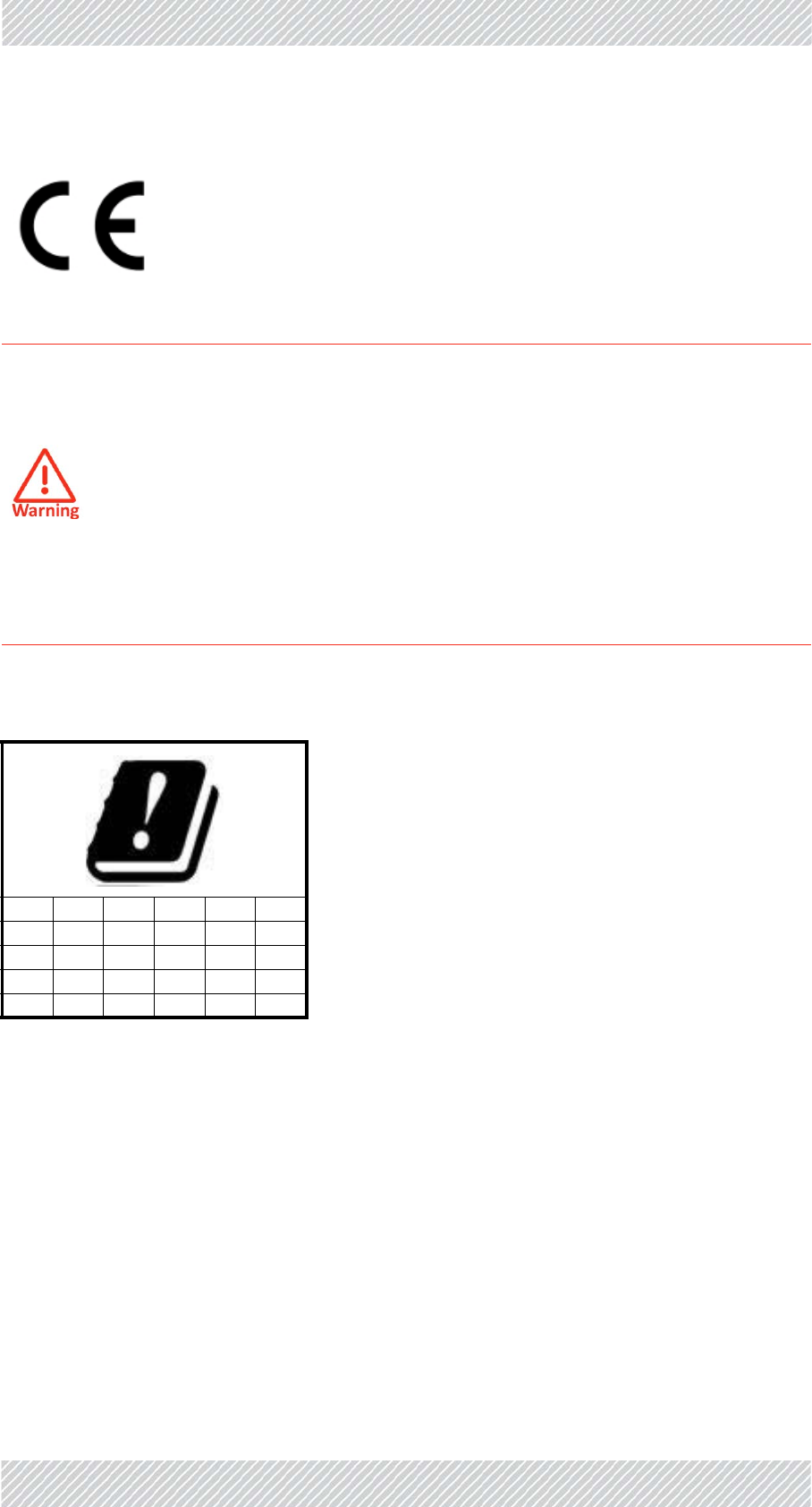
RADWIN5000InstallationGuide Release4.9.30 1‐viii
EU–Compliance
Restrictionsontheuseof5.8GHzBandinEUmemberstates
ChinaMII
OperationoftheequipmentisonlyallowedunderChinaMII5.8GHzbandregulation
configurationwithEIRPlimitedto33dBm(2Watt).
IndiaWPC
OperationoftheequipmentisonlyallowedunderIndiaWPCGSR‐38for5.8GHzband
regulationconfiguration.
RadiotransmittersoperatingintheEUneedtocomplytheRE‐DIRECTIVE
2014/53/EU,EMCDirective2014/30/EU,LowVoltageDirective2014/35/EU.
The5.8GHzproductsaresuitableforusein,andcomplywiththe
BroadbandWirelessAccessSystem(WAS).ItisaClass2deviceanduses
operatingfrequenciesthatarenotharmonizedthroughouttheEU
memberstates.Theoperatorisresponsibleforobtaininganynational
licensesrequiredtooperatethisproductandthesemustbeobtained
beforeusingtheproductinanyparticularcountry.
TheRADWIN5000JET5.8GHzproductcomplieswiththerequirementsof
theharmonizedstandardETSIEN302502andtheECC
RECOMMENDATION(06)04
BE EL LT PT BG ES
LU RO CZ FR HU SI
DK HR SK DE IT UL
NL CY AT SE IE LV
PL

RADWIN5000InstallationGuide Release4.9.30 1‐ix
Brazil
Theequipmentwilloperateonlyinthefrequencybands5470‐5725MHzand5725‐5850
MHz.ThesoftwareversiontobesoldinBrazilwithblockingisfromversion4.6.
Thepowersuppliespresentedinthisusermanualarenotsoldwiththisproduct.
Oequipamentoiráoperarapenasnasfaixasdefrequências5470‐5725MHze5725‐5850
MHz.AversãodosoftwareasercomercializadonoBrasilcombloqueioéapartirdaversão
4.6.
Asfontesdealimentaçãoapresentadasnestemanualnãoserãocomercizliadasjuntocom
esteproduto.
ForNorwayandSwedenonly
Equipmentconnectedtotheprotectiveearthingofthebuildinginstallationthroughthe
mainsconnectionorthroughotherequipmentwithaconnectiontoprotectiveearthing‐and
toacabledistributionsystemusingcoaxialcable,mayinsomecircumstancescreateafire
hazard.Connectiontoacabledistributionsystemhasthereforetobeprovidedthrougha
deviceprovidingelectricalisolationbelowacertainfrequencyrange(galvanicisolator,seeEN
60728‐11).
Norway
Utstyrsomerkoplettilbeskyttelsesjordvianettpluggog/ellerviaannetjordtilkoplet
utstyr‐ogertilkopletetkabel‐TVnett,kanforårsakebrannfare.Foråunngådetteskaldet
vedtilkoplingavutstyrettilkabel‐TVnettetinstalleresengalvaniskisolatormellom
utstyretogkabel‐TVnettet
Sweden
Utrustningsomärkoppladtillskyddsjordviajordatvägguttagoch/ellerviaannanutrust‐
ningochsamtidigtärkoppladtillkabel‐TVnätkanivissafallmedförariskförbrand.För
attundvikadettaskallvidanslutningavutrustningentillkabel‐TVätgalvaniskisolator
finnasmellanutrustningenochkabel‐TVnätet.
Unregulated
Incountrieswheretheradioisnotregulatedtheequipmentcanbeoperatedinany
regulationconfiguration,bestresultswillbeobtainedusingUniversalregulation
configuration.
SafetyPractices
ApplicablerequirementsofNationalElectricalCode(NEC),NFPA70;andtheNational
ElectricalSafetyCode,ANSI/IEEEC2,mustbeconsideredduringinstallation.
NOTES:
1.APrimaryProtectorisnotrequiredtoprotecttheexposedwiringaslongastheexposed
wiringlengthislimitedtolessthanorequalto140feet,andinstructionsareprovidedto
avoidexposureofwiringtoaccidentalcontactwithlightningandpowerconductorsin
accordancewithNECSections725‐54(c)and800‐30.

RADWIN5000InstallationGuide Release4.9.30 1‐x
Inallothercases,anappropriateListedPrimaryProtectormustbeprovided.RefertoArticles
800and810oftheNECfordetails.
2.ForprotectionofODUagainstdirectlightningstrikes,appropriaterequirementsofNFPA
780shouldbeconsideredinadditiontoNEC.
3.ForCanada,appropriaterequirementsoftheCEC22.1includingSection60andadditional
requirementsofCAN/CSA‐B72mustbeconsideredasapplicable.
4.OnlyULListedpartsandcomponentswillbeusedforinstallation.UseULListeddevices
havinganenvironmentalratingequaltoorbetterthantheenclosureratingtocloseall
unfilledopenings.
5.Usemin.10AWGexternalprotectiveearthingconductor.

RADWIN5000InstallationGuide Release4.9.30 1‐v
RADWIN 5000 HPMP
User Handbook
Notice
ThishandbookcontainsinformationthatisproprietarytoRADWINLtd(RADWINhereafter).
Nopartofthispublicationmaybereproducedinanyformwhatsoeverwithoutpriorwritten
approvalbyRADWIN.
Right,titleandinterest,allinformation,copyrights,patents,know‐how,tradesecretsand
otherintellectualpropertyorotherproprietaryrightsrelatingtothishandbookandtothe
RADWINproductsandanysoftwarecomponentscontainedthereinareproprietaryproducts
ofRADWINprotectedunderinternationalcopyrightlawandshallbeandremainsolelywith
RADWIN.
TheRADWINnameisaregisteredtrademarkofRADWIN.Noright,license,orinteresttosuch
trademarkisgrantedhereunder,andyouagreethatnosuchright,license,orinterestshallbe
assertedbyyouwithrespecttosuchtrademark.
Youshallnotcopy,reversecompileorreverseassemblealloranyportionoftheInstallation
GuideoranyotherRADWINdocumentationorproducts.Youareprohibitedfrom,andshall
not,directlyorindirectly,develop,market,distribute,license,orsellanyproductthat
supportssubstantiallysimilarfunctionalitybasedorderivedinanywayfromRADWIN
products.YourundertakinginthisparagraphshallsurvivetheterminationofthisAgreement.
ThisAgreementiseffectiveuponyouropeningofaRADWINproductpackageandshall
continueuntilterminated.RADWINmayterminatethisAgreementuponthebreachbyyouof
anytermthereof.UponsuchterminationbyRADWIN,youagreetoreturntoRADWINany
RADWINproductsanddocumentationandallcopiesandportionsthereof.
ForfurtherinformationcontactRADWINatoneoftheaddressesunderWorldwideContacts
beloworcontactyourlocaldistributor.
Disclaimer
Theparametersquotedinthisdocumentmustbespecificallyconfirmedinwritingbefore
theybecomeapplicabletoanyparticularorderorcontract.RADWINreservestherightto
makealterationsoramendmentstothedetailspecificationatitsdiscretion.Thepublication
ofinformationinthisdocumentdoesnotimplyfreedomfrompatentorotherrightsof
RADWIN,orothers.
Trademarks
WinLink1000,RADWIN2000,RADWIN5000,RADWIN6000,RADWIN600and
FiberinMotionaretrademarksofRADWINLtd.
Windows2000,XPPro,Vista,Windows7andInternetExploreraretrademarksof
MicrosoftInc.
MozillaandFirefoxaretrademarksoftheMozillaFoundation.

RADWIN5000InstallationGuide Release4.9.30 1‐vi
Otherproductnamesaretrademarksoftheirrespectivemanufacturers.

RADWIN5000InstallationGuide Release4.9.30 1‐vii
RADWINWorldwideOffices
CorporateandEMEARegionalHeadquarters
CorporateandEMEAHeadquarters
27 Habarzel Street
Tel Aviv,6971039
Israel
Tel: +972.3.766.2900
Fax: +972.3.766.2902
Email: sales@radwin.com
NorthAmericaRegional
Headquarters
900 Corporate Drive
Mahwah, NJ, 07430
USA
Tel: +1-877-RADWIN US
(+1-877 723-9468)
Tel: +1-201-252-4224
Fax: +1-201-621-8911
Email: salesna@radwin.com
Customer Support - North America:
Hours: 9 am - 6 pm EST (Mon - Fri)
Email:supportusa@radwin.com
RADWINRegionalOffices
RADWINBrazil
Av. Chucri Zaidan, 920 – 9º
São Paulo, 04583-904
Brazil
Tel: +55.11.3048-4110
Email:salesbr@radwin.com
RADWINMexico
Quinto #20 Col El Centinela
Mexico, DF, O4450
Mexico
Tel: +52 (55) 5689 8970
Email: salesmx@radwin.com
RADWINPeru
Av. Antares 213
Lima, 33
Peru
Tel: +511.6285105
Fax: +511-990304095
Email: salespe@radwin.com
RADWINIndia
E-13,B-1 Extn., Mohan Co-operative Industrial Estate
New Delhi, 110 044
India
Tel: +91-11-40539178
Email:salesin@radwin.com
RADWINPhilippines
5 Bur Bank St.
Laguna, Belair, Santa Rosa
Laguna Philippines
Tel: +63 928 7668230
Email: salesph@radwin.com
RADWINSouthAfrica
P.O. Box 3554, Rivonia
Johannesburg ,2128
South Africa
Tel: +27 (0)82 551 5600
Email: sales@radwin.com
RADWINItalyandSpain
Piazza Arenella 7/H
Napoli ,80128
Italy
Tel:+390815564116
Fax: +39335433620
Email: salesit@radwin.com
RADWINCentralAmerica
Calle La Cañada # 108-E
Jardines de la Hacienda
Ciudad Merliot El Salvador
Tel: +503 2278-5628
Email: sales@radwin.com


RADWIN5000InstallationGuide Release4.9.30 viii
LastpageofEndPagefiles