Radwin RW5XMOD RF module operating in the 4.9-5.8 GHz Band User Manual Manual r1
Radwin Ltd. RF module operating in the 4.9-5.8 GHz Band Manual r1
UserManual.wiki
>
Radwin
>
RW5XMOD User Manual
>
Manual r1
Contents
1.
Manual
2.
Manual r1
3.
User Manual
Manual r1
Navigation menu
Upload a User Manual
Namespaces
Wiki Guide
HTML
PDF
Info
Views
User Manual
Discussion / Help
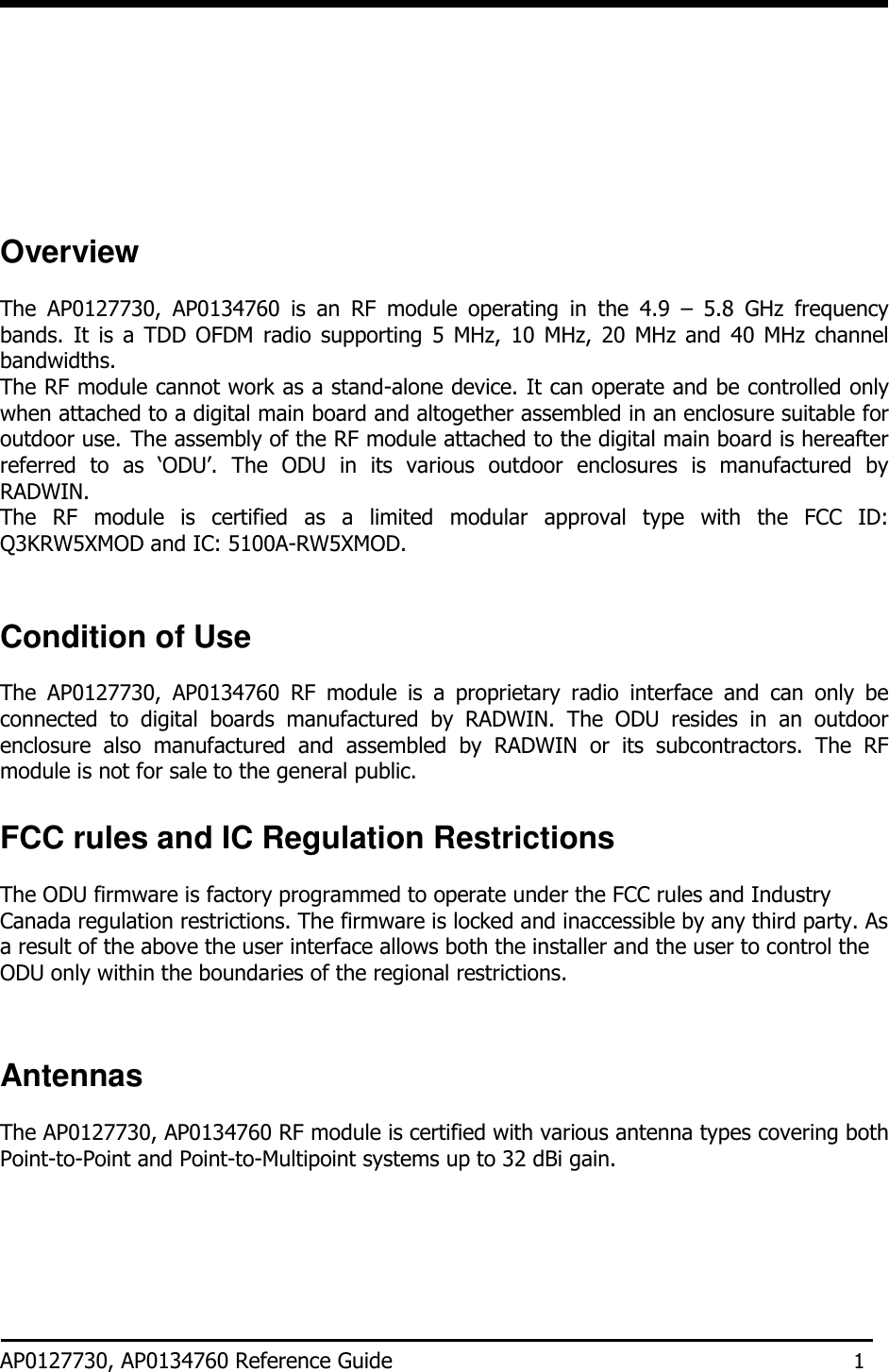
Navigation
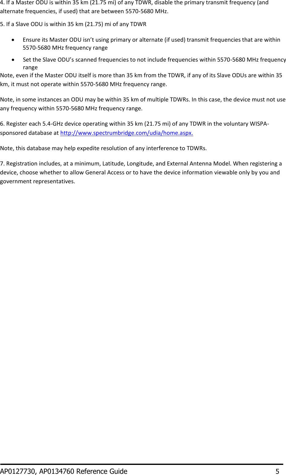
![Table 2: US FCC IDs and Industry Canada Certification Numbers and covered configurations1, 2 1. The table is relevant for all ODUs belonging to RADWIN 2000, RADWIN 5000 and RADWIN 6000 family products into which the RF Module AP0127730 or AP0134760 is assembled. 2. Under FCC ID: Q3KRW5XMOD, IC: 5100A-RW5XMOD 3. Excluding 5600-5650 MHz band Radio parameters accessed by end-user The following parameters can be accessed by user: 1. Output Power 2. Frequency channel 3. Channel bandwidth 4. Antenna gain in external antenna type device AP0127730, AP0134760 Reference Guide 7 Channel BW [MHz] Center Freq. Range [MHz] 5 5255 - 5345 10 5260 - 5340 20 5265 - 5335 40 5275 - 5320 5 5475 - 57203 10 5475 - 57203 20 5480 - 57153 40 5500 - 56953 5 5727.5 - 5847.5 10 5730 - 5845 20 5735 - 5840 40 5745 - 5830 5 4942.5 – 4987.5 10 4945 – 4985 20 4950 - 4980 5 5157 - 5245 10 5162 – 5245 20 5165 – 5240 40 5172 - 5230](https://usermanual.wiki/Radwin/RW5XMOD.Manual-r1/User-Guide-2526470-Page-10.png)