Radwin RW6000-B2 Broadband Wireless Access UTRA FDD Base Station User Manual users manual
Radwin Ltd. Broadband Wireless Access UTRA FDD Base Station users manual
Radwin >
users manual

RADWIN 6000
Small Cell Base Station
REFERENCE GUIDE
RELEASE 6.1.00p8

Regulatory Compliance
FCC - Compliance
This equipment has been tested and found to comply with the limits for a Class B digital device,
pursuant to Part 15 of the FCC Rules. These limits are designed to provide reasonable protection
against harmful interference in a residential installation. This equipment generates, uses and
can radiate radio frequency energy and, if not installed and used in accordance with the
instructions, may cause harmful interference to radio communications. However, there is no
guarantee that interference will not occur in a particular installation. If this equipment does
cause harmful interference to radio or television reception, which can be determined by turning
the equipment off and on, the user is encouraged to try to correct the interference by one or
more of the following measures:
• Reorient or relocate the receiving antenna.
• Increase the separation between the equipment and receiver.
• Connect the equipment into an outlet on a circuit different from that to which
the receiver is connected.
Consult the dealer or an experienced radio/TV technician for help.
Changes or modifications to this equipment not expressly approved by the party
responsible for compliance could void the user's authority to operate the equipment.
It is the responsibility of the installer to ensure that when using the outdoor
antenna kits in the United States (or where FCC rules apply), only those
antennas certified with the product are used. The use of any antenna other
Warning than those certified with the product is expressly forbidden by FCC rules 47
CFR part 15.204.
It is the responsibility of the installer to ensure that when configuring the
radio in the United States (or where FCC rules apply), the Tx power is set
according to the values for which the product is certified. The use of Tx
Warning power values other than those, for which the product is certified, is
expressly forbidden by FCC rules 47 CFR part 15.204.
Outdoor units and antennas should be installed ONLY by experienced
installation professionals who are familiar with local building and safety codes
and, wherever applicable, are licensed by the appropriate government
regulatory authorities. Failure to do so may void the product warranty and
may expose the end user or the service provider to legal and
Caution financial liabilities. Resellers or distributors of this equipment are not liable for
injury, damage or violation of regulations associated with the installation of
outdoor units or antennas. The installer should configure the output power
level of antennas according to country regulations and antenna type.
RADWIN 6000 Reference Guide Release 6.1.00p8 i

• Where Outdoor units are configurable by software to Tx power
values other than those for which the product is certified, it is the
responsibility of the Professional Installer to restrict the Tx power to
the certified limits.
The RADWIN 6000 band 2 should be installed and operated with a
minimum distance of 243 cm (8 ft) between the radiator and any
person and RADWIN 6000 band 5 should be installed and operated
with a minimum distance of 142 cm (4.7 ft) between the radiator
and any person
Warning
• This product was tested with special accessories - FTP CAT 5e
shielded cable with sealing gasket, 10 AWG grounding cable - which
must be used with the unit to insure compliance.
Canadian Emission Requirements for Indoor Units
This Class B digital apparatus complies with Canadian ICES-003.
Cet appareil numrique de la classe B est conforme la norme NMB-003 du Canada. ation
configuration, best results will be obtained using Universal regulation configuration.
Safety Practices
Applicable requirements of National Electrical Code (NEC), NFPA 70; and the National
Electrical Safety Code, ANSI/IEEE C2, must be considered during installation.
NOTES:
1. A Primary Protector is not required to protect the exposed wiring as long as the
exposed wiring length is limited to less than or equal to 140 feet, and instructions are
provided to avoid exposure of wiring to accidental contact with lightning and power
conductors in accordance with NEC Sections 725-54 (c) and 800-30.
In all other cases, an appropriate Listed Primary Protector must be provided. Refer to
Articles 800 and 810 of the NEC for details.
2. For protection of ODU against direct lightning strikes, appropriate requirements of NFPA
780 should be considered in addition to NEC.
3. For Canada, appropriate requirements of the CEC 22.1 including Section 60 and
additional requirements of CAN/CSA-B72 must be considered as applicable.
RADWIN 6000 Reference Guide Release 6.1.00p8 ii

RADWIN 6000
Small Cell Base Station
REFERENCE GUIDE
RELEASE 6.1.00p8
Part 1: Basic Installation

Chapter 1
Introduction
Product Overview
RW6000 is a small cell solution that provides (UMTS) HSPA+ services for cellular operators
and Broadband Wireless Access (BWA) Services for Internet Service Providers.
This compact, carrier grade and fully outdoor unit supports high capacity and high
transmission power with remarkably low power consumption. Offering an intelligent and cost
effective solution, RW6000 extends remote rural area coverage and expands capacity in
dense urban outdoor hotspots.
Product Highlights:
• 5 Watt 3GPP compliant UTRAN solution
• High capacity - Up to 24 simultaneous users
• HSPA+ data rates: 21.1 Mbps / 5.7 Mbps
• Superb coverage with maximum transmission power of 5 Watt and Rx space diversity
• Extremely low power consumption of 25 Watt
• Integrated GPS for synchronization and inventory management
• Integrated Ethernet switch with PoE
• Small, rugged and sealed enclosure to withstand extreme outdoor conditions
• High availability, no fans or moving parts
• Self-organizing capabilities for quick & easy installation and maintenance
• IPv4 support (Iu over IP only)
• RADWIN Small Cell Access point Access control
• UE Access control
• Aggregation of UE associated signaling links from multiple RADWIN Small Cell Access point
towards CN
• Terminating non-UE associated procedures towards the RADWIN Small Cell Access point
and towards the CN
RADWIN 6000 Reference Guide Release 6.1.00p8 1-1

RADWIN 6000 Chapter 1
Reference and Standards
Reference Number
Reference Description
3GPP TR 25.820
3G Home Node B (HNB) study item Technical Report
3GPP TS 22.220
Service requirements for Home Node B
3GPP TS 25.467
UTRAN architecture for 3G Home Node B (HNB); Stage 2 – UTRAN
3GPP TS 25.469
UTRAN Iuh interface Home Node B (HNB) Application Part (HNBAP) signaling
3GPP TR 21.905
"Vocabulary for 3GPP Specifications".
3GPP TS 25.468
"UTRAN Iuh Interface RUA signaling".
3GPP TS 25.469
“UTRAN Iuh Interface HNBAP signaling ".
3GPP TS 25.401
"UTRAN overall description".
3GPP TS 25.410
"UTRAN Iu Interface
RFC 4960 (September 2007)
"Stream Control Transmission Protocol".
3GPP TS 25.444
"Iuh data transport and transport signaling".
3GPP TS 25.413
"UTRAN Iu Interface RANAP Signaling".
3GPP TS 23.060
"General Packet Radio Service (GPRS); Service Description; Stage 2".
3GPP TS 22.220
"Service requirements for Home NodeBs and Home eNodeBs".
3GPP TS 25.419
"UTRAN Iu Interface
What’s in the Box
The RADWIN 6000 packages include the following items:
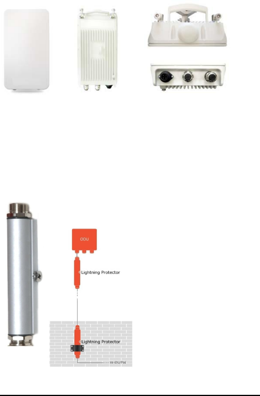
• One RADWIN 6000 ODU - see Figure 1-2 below for front and rear view
• An ODU mounting kit - see Figure 1-1 below
• Two cable glands (to be used with CAT 5e PoE out cable)
• One AC/DC cable gland
• One 0.5 meter 10 AWG grounding cable
• DC/AC Power connector
• One short power cable (BD)
Figure 1-1: RADWIN 6000 Mounting kit
RADWIN 6000 Reference Guide Release 6.1.00p8 1-2
RADWIN 6000 Chapter 1
The RADWIN 6000ODU is shown in Figure 1-2 below:
Figure 1-2: Left, front, center rear, right top, top ports, right bottom, bottom ports
Related Equipment and Accessories
Lightning Protector
Lightning protection is mandatory for radio links. RADWIN supplies a lightning
protector device designed for use with RADWIN products.
Figure 1-14:
Left: RADWIN Lightning Protector Right:
Using
RADWIN
lightning protectors
RADWIN 6000 Reference Guide Release 6.1.00p8 1-3

Chapter 2
Hardware Installation
This chapter sets out the requirements and procedures for the hardware installation of
the RADWIN 6000. It is intended to guide qualified field technicians.
Warning
Outdoor units and antennas should be installed ONLY by experienced
installation professionals who are familiar with local building and safety
codes and, wherever applicable, are licensed by the appropriate
government regulatory authorities. Failure to do so may expose the end
user or the service provider to legal and financial liabilities. RADWIN and
its resellers or distributors are not liable for injury, damage or violation of
regulations associated with the installation of outdoor units or antennas.
Safety Practices
Preventing overexposure to RF energy
To protect against overexposure to RF energy, install the ODU so as to provide and maintain
minimal separation distances from all persons.
When the system is operational, avoid standing directly in front of the antenna. Strong RF
fields are present when the transmitter is on. The ODU must not be deployed in a location
where it is possible for people to stand or walk inadvertently in front of the antenna.
Grounding
All RADWIN products should be grounded during operation. In addition:
• The ODU should be earthed by a wire with diameter of at least 10 AWG.
The RADWIN 6000 ODU must be properly grounded to protect against
lightning. It is the user's responsibility to install the equipment in accordance
with Section 810 and Article 725 of the National Electric Code, ANSI/NFPA
No.70-1984 or Section 54 of the Canadian Electrical Code. These codes
describe correct installation procedures for grounding the outdoor unit, mast,
lead-in wire and discharge unit. It also lays down the size of grounding
conductors and connection requirements for grounding electrodes.
RADWIN 6000 Reference Guide Release 6.1.00p8 2-1

Hardware Installation Chapter 2
The RADWIN 6000 ODU must be grounded to a Protective Earth as described in
and in accordance with the Local Electrical Regulations.
Further, you should -
• Always make the ground connection first and disconnect it last
• Never connect telecommunication cables to ungrounded equipment
• Ensure that all other cables are disconnected before disconnecting the ground
Protection against Lightning
The use of lightning protection is dependent on regulatory and end user requirements. All
of RADWIN outdoor units are designed with surge limiting circuits to minimize the risk of
dam-age due to lightning strikes. RADWIN recommends the use of additional lightning
protector devices to protect the equipment from nearby lightning strikes.
See Chapter 3 for detailed installation instructions of lightning protection devices.
General
It is recommended that installation of an outdoor unit be contracted to a professional
installer.
• Before working on equipment connected to power lines or telecommunication lines,
you should remove jewelry or any other metallic object that may come into contact
with energized parts.
• Use extreme care when installing antennas near power lines.
• Use extreme care when working at heights.
• When using an AC power source for RADWIN 6000 PoEs always use the AC power
adapter supplied by RADWIN.
• Use the right tools. In addition to standard tools required for any kind of ODU or
antenna installation, RADWIN 6000 ODUs require additional specific tools detailed on
page 2-4 below.
Package Contents
The RADWIN 6000 packages include the following items:
• One RADWIN 6000- see Figure 2-5 below for front and rear view
• An ODU mounting kit - see Figure • below
• A CD containing -
the RADWIN Manager
User Manual
• Label showing the MAC address and the alternative Community string. The label is
self-adhesive. You should keep this label safe
• Two cable glands (to be used with CAT 5e cables)
• One AC/DC cable gland
• One 0.5 meter 10 AWG grounding cable
• AC Power cable RADWIN 6000 Mounting kit
RADWIN 6000 Reference Guide Release 6.1.00p8 2-2

Hardware Installation Chapter 2
Table 2-1: Bill of Materials: ODU mounting kit
Figure 2-1: Large Clamp Figure 2-2: Small Clamp Figure 2-3: Arm Figure 2-4: Accessories
The RADWIN 6000 ODU is shown in Figure 2-5 below:
Figure 2-5: Left, front, center rear, right top, top ports, right bottom, bottom ports
Additional Tools and Materials Required
The following is a list of the equipment and materials required to install RADWIN 6000
hardware.
RADWIN 6000 Reference Guide Release 6.1.00p8 2-3
Item
Qty
Large Clamp (see Figure 2-1)
1
Small Clamp (see Figure 2-2)
1
Arm (see Figure 2-3)
1
Screw hex head M8x40 4
4
Screw hex head M8x70 2
2
Washer flat M8 4
4
Washer spring M8 3
3
M8 Nuts 2
2

Hardware Installation Chapter 2
Tools and Materials
• Crimping tool for RJ-45 (if the ODU-PoE cable is without connectors)
• Spanner/wrench 13 mm (½”)
• Drill (for wall mounting only)
• Cable ties
• Sealing material
Cables and connectors
• CAT 5e LAN cable
• PoE-out cable (outdoor class, CAT-5e, 4 twisted pairs, 24AWG), up to 100 m. for
100BaseT connection. For a 1000BaseT connection (HBS only) use an ODU-PoE cable
no longer than 75m.
For 1000BaseT, you should use RADWIN supplied ODU-PoE cables, which
guarantee 1Gb performance. RADWIN cannot guarantee 1Gb performance
Note if you use third party cables.
Outdoor installation
Mounting the ODU
The ODU can be mounted on a pole or a wall. In both installations, the supplied mounting
kit is used to secure the ODU.
A mast-sited ODU typically uses a pole attached to the mast.
Note
Prior to connecting cables to the ODU, the protective earth terminal (screw)
of the ODU must be connected to an external protective ground conductor
or to a grounded pole.
Warning
• Only a qualified person using the proper safety equipment should
climb the antenna mast
• Only qualified professional personnel should install or dismantle
ODUs and masts
To mount the ODU on a pole or a wall:
1. Ensure that the ODU is properly grounded.
2. Mount the ODU onto the pole or wall. Ensure that the unit is oriented so that the
cable connectors are at the bottom. (If they are on top, water may penetrate
into the unit causing damage.) It is possible to mount an ODU horizontally.
3. Refer also to for detailed ODU mounting kit contents and schematics.
RADWIN 6000 Reference Guide Release 6.1.00p8 2-4

Hardware Installation Chapter 2
Mounting the Lightning Protection Devices
The use of lightning protection is dependent on regulatory and end user requirements. The
RADWIN 6000 ODU is designed with surge limiting circuits to minimize the risk of damage
due to lightning strikes. RADWIN recommends the use of additional lightning protector
devices to protect the equipment from nearby lightning strikes.
Refer to Chapter 4 for detailed installation instructions for use of lightning
protection devices.
Outdoor Connections
To complete the outdoor connections:
1. Connect the ground cable to the ODU chassis as marked on the ODU.
2. Connect the lightning protection device to the ODU (see Chapter 4).
3. Attach the ODU-IDU cable to the PoE RJ-45 connector
4. Attach the LAN cable to the LAN RJ-45 connector.
5. Screw in the cable glands to ensure hermetic sealing of the ODU.
6. Secure the cables to the pole, mast or brackets using UV-rated cable ties.
RADWIN 6000 Reference Guide Release 6.1.00p8 2-5
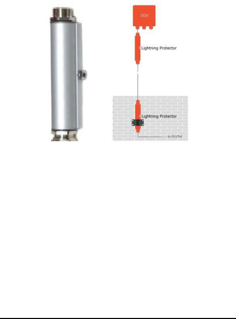
Mounting the Lightning Protection Devices
The use of lightning protection is dependent on regulatory and end user requirements. The
RADWIN 6000 ODU is designed with surge limiting circuits to minimize the risk of damage
due to lightning strikes. RADWIN recommends the use of additional lightning protector
devices to protect the equipment from nearby lightning strikes.
Figure 2-6: RADWIN Lightning Protector Right: Using RADWIN lightning protectors
RADWIN 6000 Reference Guide Release 6.1.00p8 2-6

Chapter 3
Lightning Protection and
Grounding Guidelines
Meticulous implementation of the guidelines in this chapter will provide best protection
against electric shock and lightning.
100% protection is neither implied nor possible.
Warning
Note
This chapter is at best a guide. The actual degree of lightning
protection required depends on local conditions and regulations.

Using Lightning Protectors and Grounding Chapter 3
The RADWIN Lightning Protection System consists of the following components:
•
• Grounding for ODU
• External Primary Lightning Protector units and grounding for the outdoor cable
• Internal ESD protection circuits over the Power/Telecom lines
ODU Grounding
RADWIN Lightning Protection System uses a Shielded CAT 5e cable to interconnect the
Outdoor (ODU) and Indoor (IDU) units.
However, this shielding does not provide a good lightning discharge path, since it can not
tolerate the high Lightning Current surges.
To provide an alternate Lightning Discharge path, the ODU grounding posts should be
connected to ground point by a 10 AWG short copper wire.
The device should be permanently connected to ground.
RADWIN 6000 Reference Guide Release 6.1.00p8 3-2
Using Lightning Protectors and Grounding Chapter 3
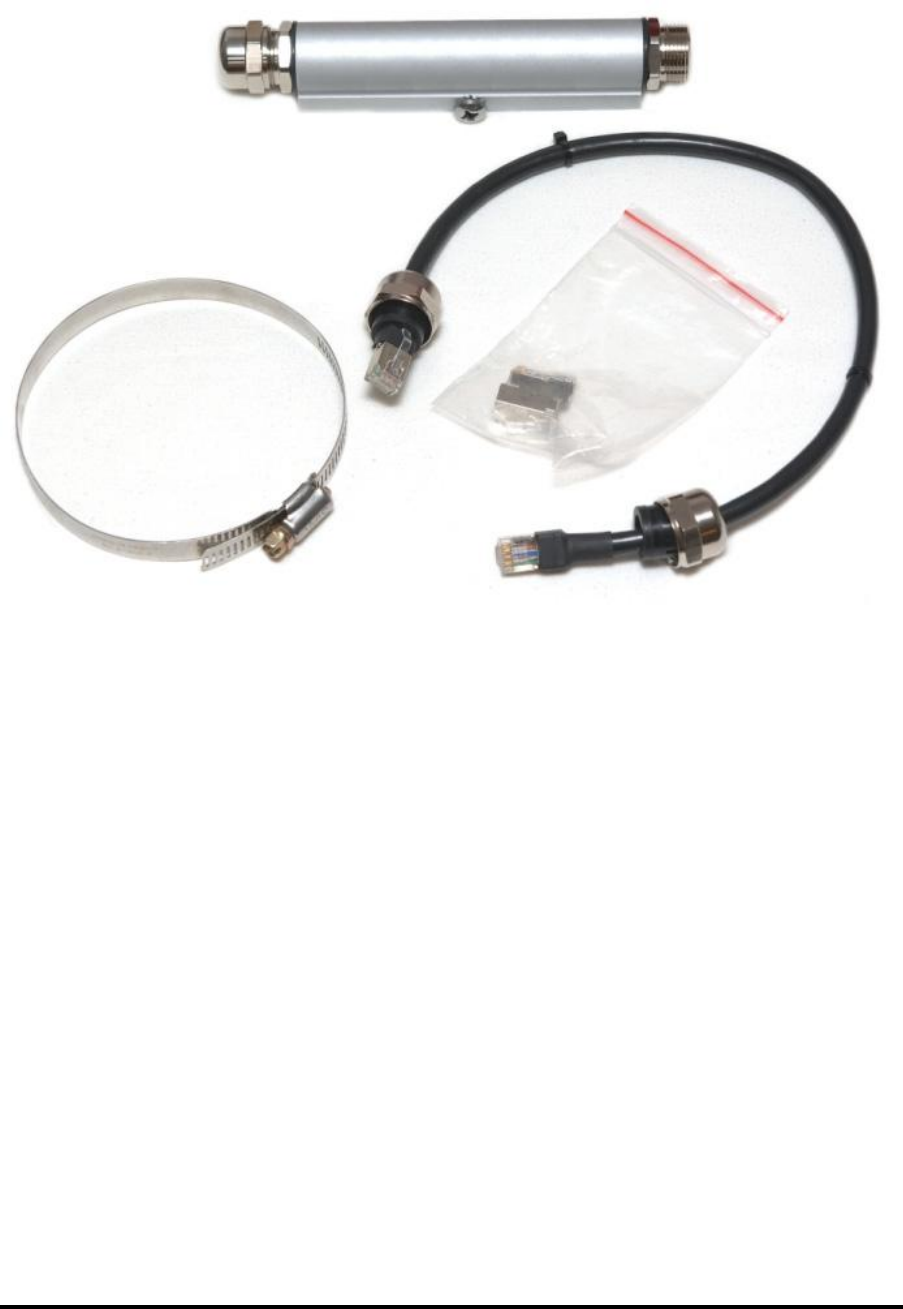
The RADWIN Lightning Protection Kit
The RADWIN lightning protection kit contains the items as shown in Figure 3-2:
Figure 3-2:
RADWIN
Lightning Protection Kit
The lightning protector incorporates high-power gas discharge tube and current
transistor protection in a single protector unit. Technical specifications are shown in .
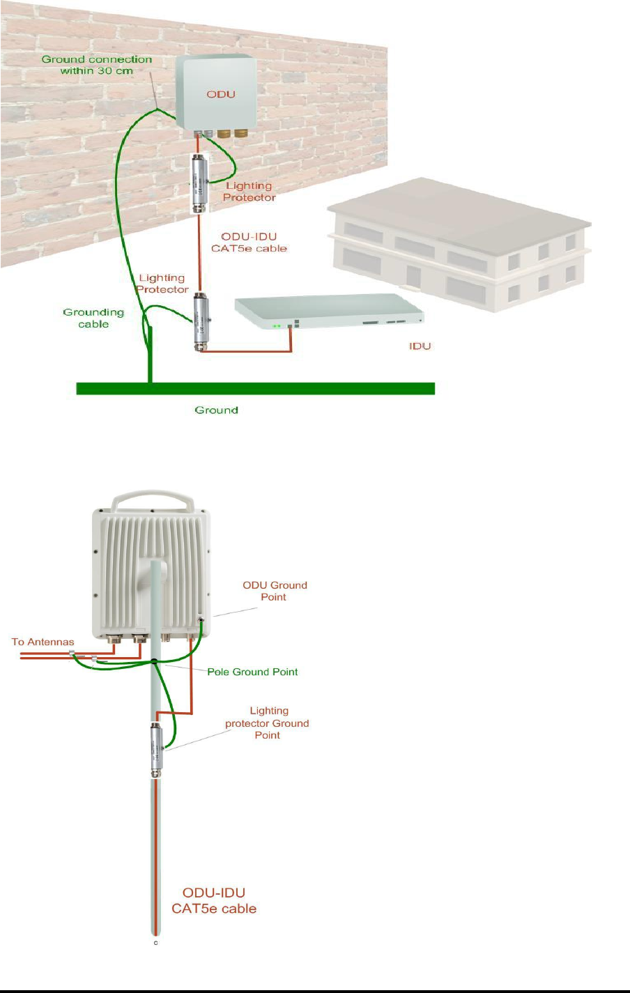
Using Lightning Protectors and Grounding
A Grounding Kit and lightning protector Unit must be located near the ODU and
properly grounded as illustrated in Figures 3-3 and 3-4 below:
RADWIN 6000 Reference Guide Release 6.1.00p8 3-3
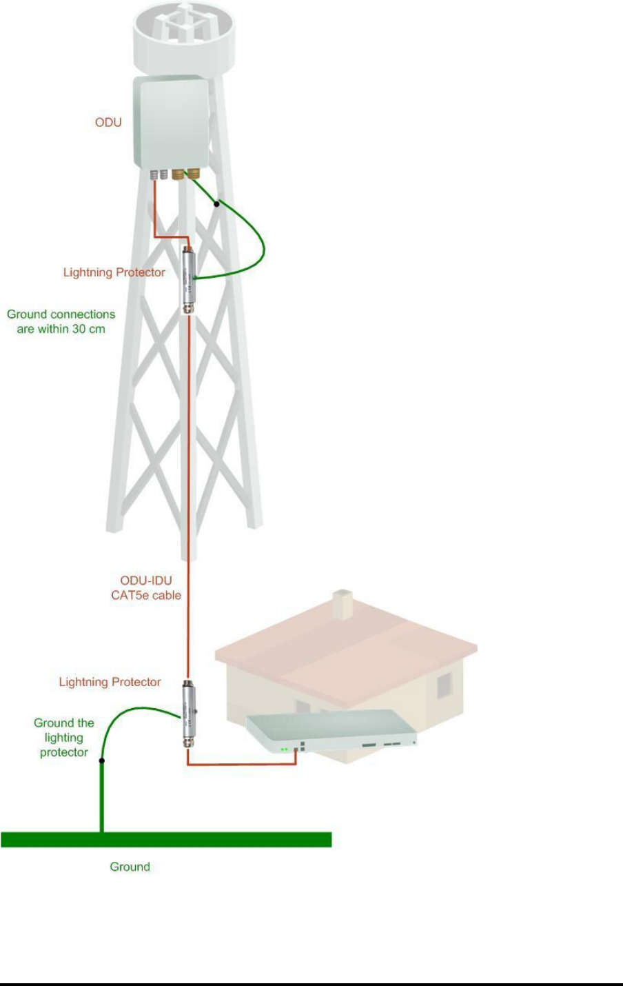
Using Lightning Protectors and Grounding Chapter 3
Figure 3-3: Grounding a typical pole installation
RADWIN 6000 Reference Guide Release 6.1.00p8 3-4
Using Lightning Protectors and Grounding Chapter 3
Figure 3-4: Grounding a typical wall installation
The next figure shows a close-up of the rear of grounded ODU:
Figure 3-5: ODU Lightning Protector and grounding
RADWIN 6000 Reference Guide Release 6.1.00p8 3-5

Using Lightning Protectors and Grounding Chapter 3
Mounting RADWIN Lighting Protection unit
To mount a lightning protection device:
Mount the device as close to the ODU as possible.
Mount the unit to on the pole using the supplied band.
Connect the ODU-IDU cable using the RJ-45 jack.
Connect one cable between the ODU and the protector using an RJ-45 jack.
Connect the protector’s ground stud to a grounding point. Use the appropriate
wire gauge and type, keeping the wire as short as possible, less than 1m (3’),
between the stud and the site grounding point.
There may also be regulatory requirements to cross bond the ODU-IDU CAT-
5e cable at regular intervals up the mast. This may be as frequent as every
Note
10 meters (33 feet).
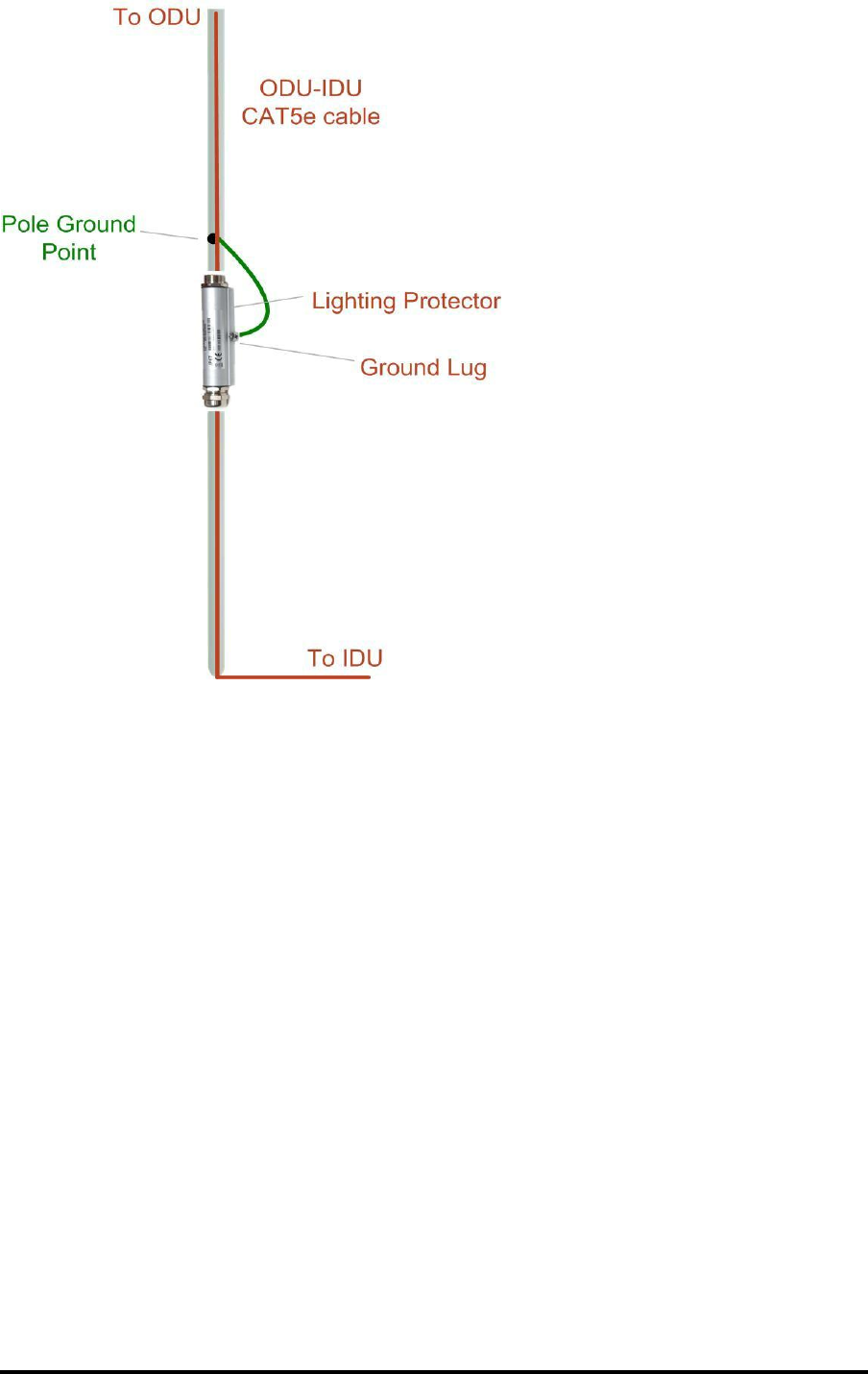
A second lightning protector Unit should be mounted at the building entry point and must
be grounded, as shown in Figure 3-4 above.
To mount the lightning protection at the building entry point:
1. Mount the device outside the building, located as near as possible to the entrance
of the CAT 5e ODU-IDU cable.
2. Mount the unit to on the pole using the supplied band.
3. Connect the ODU-IDU cable using the RJ-45 jack.
4. Connect one cable between the IDU and the protector using an RJ-45 jack.
5. Connect the protector’s ground stud to a grounding point. Use the appropriate
wire gauge and type, keeping the wire as short as possible, less than 1m (3’),
between the stud and the site grounding point.
RADWIN 6000 Reference Guide Release 6.1.00p8 3-6
Using Lightning Protectors and Grounding Chapter 3
Figure 3-6: Lightning protector and grounding at building entry point
Internal ESD Protection circuits
RADWIN equipment is designed to meet the ETSI/FCC/Aus/NZ/CSA EMC and Safety
require-ments. To fulfill these requirements, the system's Telecom lines at the ODU/IDU are
Trans-former-isolated and include internal ESD (Electro-Static-Discharge) Protection circuits.
RADWIN 6000 Reference Guide Release 6.1.00p8 3-7

Appendix A
Technical Specifications
Scope of these Specifications
This appendix contains technical specifications for the RADWIN 6000 appearing in this
User Manual. They are correct at the date of publication, but are intended for general
background only. The latest authoritative and most up to date technical specifications are
available as Data Sheets obtainable from RADWIN Customer Service.
In any event, RADWIN reserves the right to change these specifications without notice.
ODU - RADWIN 6000
Capacity
24 simultaneous users
Range
Up to 3 km
Maximum data range
21.1 Mbps / 5.7 Mbps
Basic configuration
Small form factor outdoor unit connectorized for external cellular antennas
Integrated GPS Synchronization
Supported
Integrated GLONASS Synchronization
option
IEEE 1588
option
Tx Power
Configurable from 100mW up to 5 Watt (37 dBm), controlled by 1 dB step
Rx Diversity
Supported
Spectrum Sniffing
Supported (UMTS, GSM)
Power Supply
44-60 VDC or 90-264 VAC
Power Consumption
< 25W (typical)
Band
UL Frequencies (MHz)
DL Frequencies (MHz)
Band II (PCS)
1850–1910
1932.4–1987.6
Band V (CLR) (850)
824 - 849
871.4 – 891.6
RADWIN 6000 Reference Guide Release 6.1.00p8 A-1

Tech Spec
Appendix A
Environmental
Operating Temperatures
- 30°C to +50°C / - 22°F to +122°F
Humidity
Up to 100% non-condensing, IP67
Storage
-40° to 85°C / -40°F to 185°F
Safety
FCC/IC (cTUVus)
UL 60950-1, UL 60950-22, CAN/CSA C22.2 60950-1, CAN/CSA C22.2 60950-22
ETSI/IEC
EN/IEC 60950-1, EN/IEC 60950-22
EMC
FCC
47 CFR Class B, Part15, Subpart B
ETSI
EN 301 489-1, EN 301 489-23, EN 301 489-17
CAN/CSA
CISPR 22-04 Class B
AS/NZS
CISPR 22:2004 Class B
Interfaces
Local Connection / Transmission
10/100BaseT RJ45
Transmission and PoE
10/100BaseT RJ45, 802.3af/at PoE (legacy mode)
Core Network connectivity
Iuh 3GPP Release 9, 3GPP TS 25.467, 3GPP TS 25.468, 3GPP TS 25.469
Management
TR-196/TR-069, SNMPv3, Web based, CLI
Mechanical
Dimensions
360(h) x 200(w) x 70(d) mm / 360(h) x 200(w) x 90(d) mm with backhaul
option
Weight
4.5 kg / 5.5 kg with backhaul option
Volume
1.7 liter / 2 liter with backhaul option
Mount
Mast or wall mountable
RADWIN 6000 Reference Guide Release 6.1.00p8 A-2

Tech Spec
Appendix A
Lightning Protector
Electrical
Compatible Interfaces
10/100/1000BaseT
Data Rates
Up to 1000Mbps
Nominal Operational Voltage
48 VDC
Maximum Operational Voltage
60 VDC - 650 mA
Maximum Continues current
1 A
Impedance
90 to 110 Ohm
Connection type
RJ45 CAT 5e STP (shielded)
Pin-out
8 wires + shielding
Pins Protected
All pins protected
Response time
<5 microseconds (with ODU)
Nominal discharge currents
Line to Line
500 A @ 8/20μs
Line to Ground
2000 A @ 8/20 μs
Impulse Discharge Current
20000 A, 8/20 μs
1 operation minimum
10000 A, 8/20 μs
> 10 operations
2000 A, 10/350 μs
1 operation
200 A, 10/1000 μs
> 300 operations
200 A, 10/700 μs
> 500 operations
Impulse Spark-over
DC Spark-over ±20 % @ 100 V/s
150 V
100 V/μs
350 V
1000 V/μs
500 V
Capacitance
< 2 pF
DC Holdover Voltage
80V
Mechanical
Enclosure
Metal
Connection to bonding Network
Screw
Dimensions
150mm
Weight
220 gram (0.22Kg)
Environmental
Operating temperature
-40 to +60
Storage temperature
-50 to +70
RADWIN 6000 Reference Guide Release 6.1.00p8 A-3

Antenna Characteristics
Appendix A
Enclosure rating
IP67
Humidity
100% non condensing
RADWIN 6000 Reference Guide Release 6.1.00p8 A-4