Radwin WINLINK Point to Point Wireless TX User Manual Airmux 104 fm
Radwin Ltd. Point to Point Wireless TX Airmux 104 fm
UserManual.wiki
>
Radwin
>
WINLINK User Manual
Users Manual
Navigation menu
Upload a User Manual
Namespaces
Wiki Guide
HTML
PDF
Info
Views
User Manual
Discussion / Help
Navigation


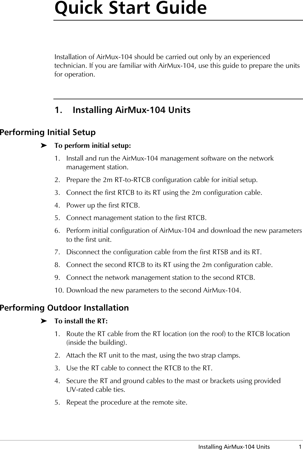

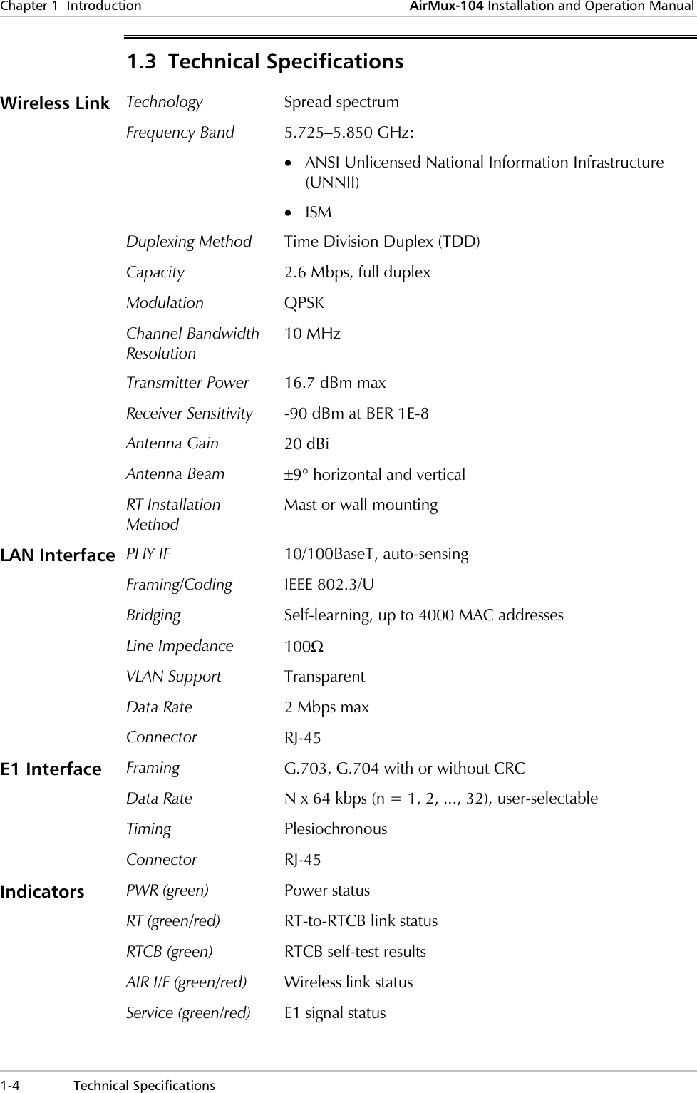

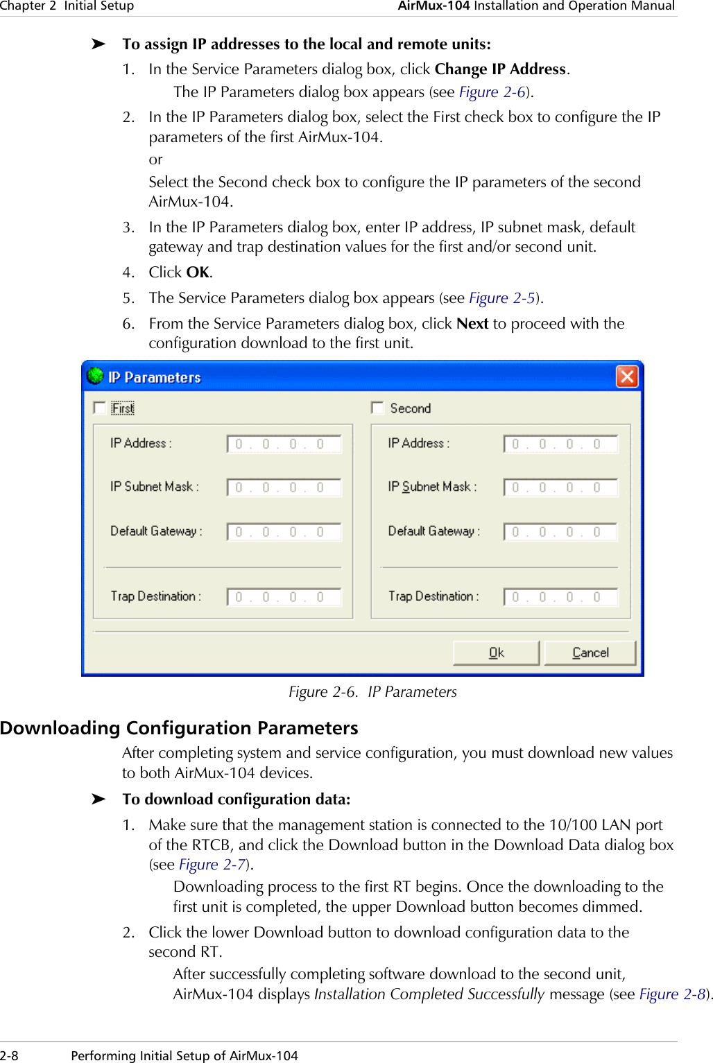
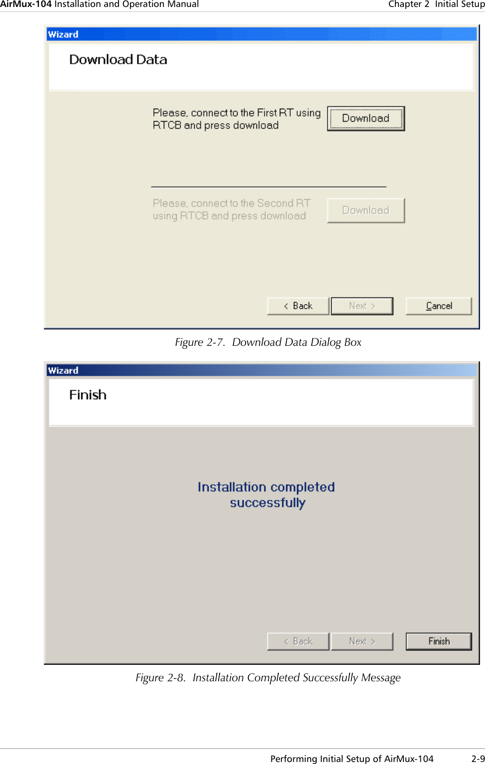
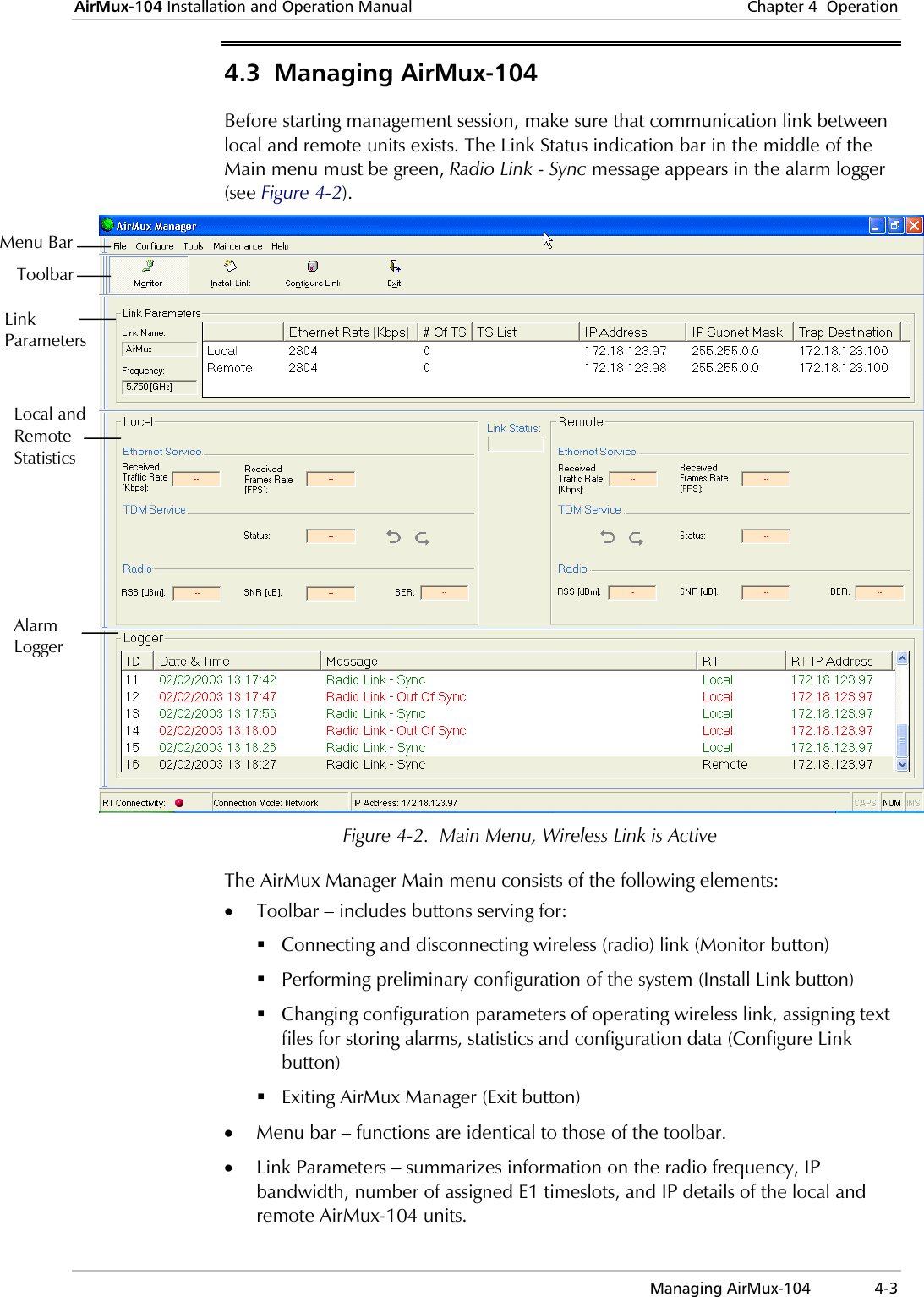
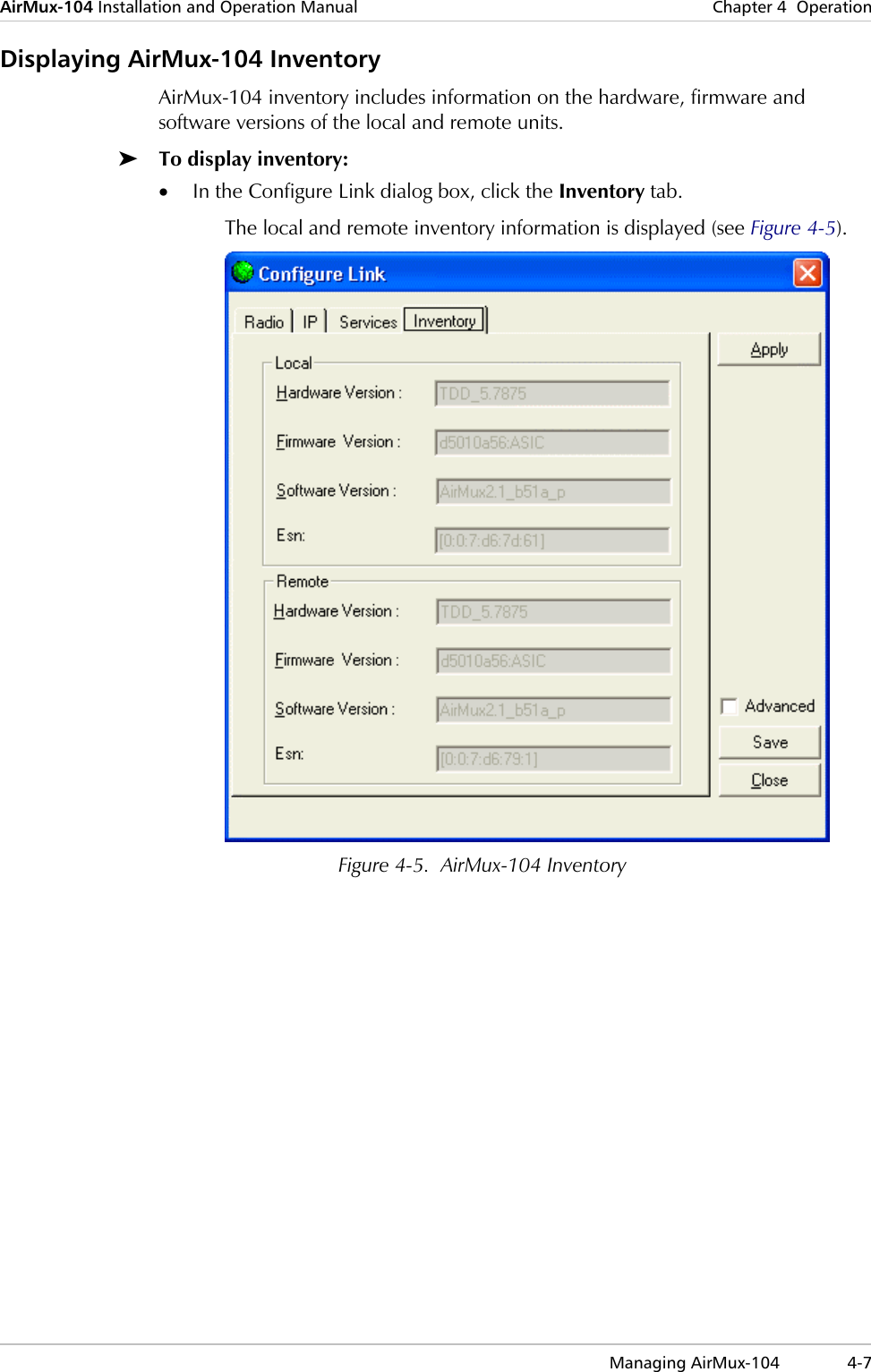
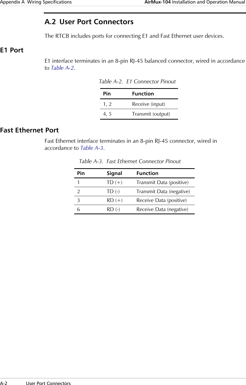
![AirMux-104 Installation and Operation Manual Chapter 2 Initial Setup Performing Initial Setup of AirMux-104 2-7 Table 2-2. Correlation between the Number of Assigned Timeslots and Remaining Ethernet Bandwidth Number of E1 Timeslots Remaining Ethernet Bandwidth [kbps] 0 2304 1 2208 2 2112 3 1920 4 1920 5 1920 6 1824 7 1728 8 1728 9 1536 10 1536 11 1536 12 1440 13 1440 14 1248 15 1248 16 1248 17 1152 18 1152 19 1056 20 864 21 864 22 864 23 768 24 672 25 672 26 480 27 480 28 384 29 384 30 288 31 96 32 96](https://usermanual.wiki/Radwin/WINLINK/User-Guide-339329-Page-28.png)