Radwin WL1000F49 Point to Point Radio System User Manual WinLink 1000
Radwin Ltd. Point to Point Radio System WinLink 1000
Radwin >
Users Manual

W
i
n
Lin
k
™100
0
Installation and Operation Manual
Point-to-Point Wireless
Product Family
Revision 3.0

WinLink 1000
Point-to-Point Wireless TDM/IP Revision 3.0
Installation and Operation Manual
Notice
This manual contains information that is proprietary to RADWin Ltd. ("RADWIN"). No
part of this publication may be reproduced in any form whatsoever without prior written
approval by RADWIN Ltd.
Right, title and interest, all information, copyrights, patents, know-how, trade secrets
and other intellectual property or other proprietary rights relating to this manual and to
the WinLink 1000 and any software components contained therein are proprietary
products of RADWIN protected under international copyright law and shall be and
remain solely with RADWIN.
WinLink 1000 is a registered trademark of RADWIN. No right, license, or interest to such
trademark is granted hereunder, and you agree that no such right, license, or interest
shall be asserted by you with respect to such trademark.
You shall not copy, reverse compile or reverse assemble all or any portion of the Manual
or the WinLink 1000. You are prohibited from, and shall not, directly or indirectly,
develop, market, distribute, license, or sell any product that supports substantially
similar functionality as the WinLink 1000, based on or derived in any way from the
WinLink 1000. Your undertaking in this paragraph shall survive the termination of this
Agreement.
This Agreement is effective upon your opening of the WinLink 1000 package and shall
continue until terminated. RADWIN may terminate this Agreement upon the breach by
you of any term hereof. Upon such termination by RADWIN, you agree to return to
RADWIN the WinLink 1000 and all copies and portions thereof.

For further information contact RADWIN at the address below or contact your local
distributor.
International Headquarters RADWIN Ltd.
32 Habarzel Street
Tel Aviv 69710 Israel
Tel: 972-3-7662900
Fax: 972-3-7662902
E-mail: support@radwin.com
U.S. Headquarters RADWIN Inc.
900 Corporate Drive
Mahwah, NJ 07430 USA
Tel: (201) 529-1100Fax: (201) 529-
5777
E-mail: support-usa@radwin.com

FCC-15 User Information
This equipment has been tested and found to comply with the limits for a
Class B digital device, pursuant to Part 15 of the FCC Rules. These limits
are designed to provide reasonable protection against harmful interference
in a residential installation. This equipment generates, uses and can
radiate radio frequency energy and, if not installed and used in accordance
with the instructions, may cause harmful interference to radio
communications. However, there is no guarantee that interference will not
occur in a particular installation. If this equipment does cause harmful
interference to radio or television reception, which can be determined by
turning the equipment off and on, the user is encouraged to try to correct
the interference by one or more of the following measures:
-- Reorient or relocate the receiving antenna.
-- Increase the separation between the equipment and receiver.
-- Connect the equipment into an outlet on a circuit different
from that to which the receiver is connected.
Consult the dealer or an experienced radio/TV technician for help.
Changes or modifications to this equipment not expressly approved by the party
responsible for compliance (RADWIN) could void the user’s authority to operate the
equipment.
It is the responsibility of the installer to ensure that when using the
outdoor antenna kits in the United States (or where FCC rules apply),
only those antennas certified with the product are used. The use of
any antenna other than those certified with the product is expressly
forbidden in accordance to FCC rules CFR47 part 15.204.
Warning

Installing WinLink 1000 Units 1
Quick Start Guide
Installation of WinLink 1000 should be carried out only by a qualified
technician. If you are familiar with WinLink 1000, use this guide to
prepare the units for operation.
1. Installing WinLink 1000 Units
ODU Package Contents:
• ODU
• Mast/Wall mounting kit
• WinLink 1000 Management software installation CD
• Mounting instructions
• Spare RJ-45 connector
• ODU to IDU cable at length ordered (optional)
IDU-E Package Contents:
• IDU-E
• 110V/240V adaptor
• IDU wall-mounting drilling template
• Spare RJ-45 connector
(Optional) IDU-C Package Contents:
• IDU-C
• For AC model, 110v/240 VAC with 3-prong connector cable
• For DC model, -48 VDC with 3-pin terminal block connector (green)
• IDU standard 1-U, 19” carrier rack
• Spare RJ-45 connector
Equipment Required:
• RJ-45 crimp tool (If pre-assembled cable is not used)

Quick Start Guide WinLink 1000 Installation and Operation Manual
2 Installing WinLink 1000 Units
• Drill (for wall mounting only)
• IDU and ODU grounding cable
• 13 mm or 1/2″ socket spanner
• ODU to IDU cable if not ordered (Outdoor class, CAT-5e, 4 twisted
pairs)
• Cable ties
• Laptop running Windows 2000 or Windows XP
Before the installation
1. Install the WinLink 1000 software on the laptop.
2. Verify that all equipment and tools are available.
Performing Installation
Î To install the ODU:
1. At site A, route the ODU cable from the ODU location (on the roof) to
the IDU location (inside the building). The maximum length is 100m.
2. Mount the ODU unit to the mast or wall, using the mounting kit.
3. Connect the RJ-45 connectors to both ends of the cable, use the
pinout table and diagram below:
IDU RJ-45 Wire Color Function ODU RJ-45
1 White/Green Ethernet (RxN) 1
Twisted 2 Green Ethernet (RxT) 2
3 White/Orange Ethernet (TxT) 3
Twisted 4 Blue Power (+) 4
5 White\Blue Power (+) 5
Twisted 6 Orange Ethernet (TxN) 6
7 White/Brown
Power (−) 7
Twisted 8 Brown
Power (−) 8
4. Secure the ODU and ground cables to the mast or brackets using
cable ties.
5. Repeat the procedure at site B.

WinLink 1000 Installation and Operation Manual Quick Start Guide
Installing WinLink 1000 Units 3
Î To align the ODU:
1. Connect power to the IDU.
Do not stand in front of a live outdoor unit.
The antenna used for this transmitter must be installed to provide a
separation distance of at least 200 cm from all persons and must not be
co-located or operating in conjunction with any other antenna or
transmitter.
2. Align the site A ODU in the direction of the site B ODU.
3. Align the site B ODU in the direction of the site A ODU.
4. Alternating between each site, turn each ODU slowly listening to the buzzer
beep sequence until optimal alignment is achieved.
5. Secure the site A and site B ODUs to the mast/wall.
6. Monitor the link quality for about 15 minutes to verify stability.
7. Connect the management station to one of the two IDUs in the link.
8. Start the WINLink Manager application.
9. Open the installation wizard and follow the installation steps.
10. After selection of the radio channel and the link rate, verify that the
link quality bar in the WinLink manager is within the green range for
TDM service and within the yellow range for Ethernet service.
Achieve the best possible link quality values. In case of radio link loss,
verify the ODU alignment, or change the radio channel in both sides of
the link. When the radio link resumes continue the installation process.
Connecting User Equipment
Î To connect user equipment to the IDU:
1. Connect the user equipment (such as PBX) to the IDU RJ-45 port
designated Trunk:
On the rear panel of the IDU-E.
On the front panel of the IDC-C,
2. Connect user hub/router or any other compatible device to the IDU
RJ-45 port designated LAN:
On the rear panel of the IDU-E.
Not
e
Warning

Quick Start Guide WinLink 1000 Installation and Operation Manual
4 Operating WinLink 1000
On the front panel of the IDU-C.
IDU-C has an integrated LAN switch that provide 2 port of 10/100BaseT.
The Integrated LAN switch is not support spanning tree.
The two LAN ports can be connected to 2 separated LAN segments but
connection of both LAN ports to the same LAN segment will create a loop
that fluid the network. Therefore, this configuration is prohibited.
2. Operating WinLink 1000
WinLink 1000 requires no operator attention once installed, with the
exception of occasional monitoring of front panel indicators and statistics
data. Intervention is only required when WinLink 1000 must be
configured to its operational requirements or diagnostic tests are
performed:
Normal Indications
Upon turning on WinLink 1000, the PWR LED in the front panel lights to
indicate that WinLink 1000 is on. The table below shows the correct
status of the indicators after power-up.
Indicator Color Status
PWR Green On (only on IDU-E)
IDU Orange
Green
Blinks for short duration during startup
Blinking slowly shows normal operation
ODU Green Blinking slowly shows normal operation
AIR I/F Orange
Green
Blinks for short duration during startup
Blinking slowly shows normal operation
SERVICE Green Blinking slowly shows normal operation
OFF when SERVICE selected is Ethernet only
Note

WinLink 1000 Installation and Operation Manual Quick Start Guide
Operating WinLink 1000 5
Troubleshooting
If the WinLink 1000 is not operational, determine the cause and solution
from the table below.
Led Status Remedy
PWR Off For the IDU-E, check that AC adapter is connected
to the IDU and the AC power outlet.
IDU Orange Check that the IDU/ODU cable is properly wired
and connected.
ODU Red Check that the IDU/ODU cable is properly wired
and connected.
Orange Complete the installation procedure from the
management software.
AIR I/F
Red Check the ODU Antenna alignment. Check that
the radio configuration of both site A and site B
units are the same (channel and SSID).
Off Check the TDM service configuration in the NMS.
Orange Check that the system is not in loopback mode.
Check the site B IDU ports and cables and site B
external equipment.
SVC.
Red Check the site A IDU ports, cables and external
equipment.

Contents
Chapter 1. Introduction
1.1 Overview .................................................................................................. 1-1
Application....................................................................................................... 1-1
Features........................................................................................................... 1-2
1.2 Physical Description.................................................................................. 1-4
Chapter 2. Installation and Setup
2.1 WinLink 1000 System ............................................................................... 2-1
2.2 Site Requirements and Prerequisites .........................................................2-2
2.3 Package Contents .....................................................................................2-2
2.4 Installation and Setup ............................................................................... 2-3
Mounting the ODU ........................................................................................... 2-4
Connecting the ODU to the IDU ........................................................................ 2-5
Connecting the Power ...................................................................................... 2-6
Installing WinLink 1000 Management Software ................................................. 2-7
Aligning the WinLink 1000 ODUs...................................................................... 2-9
Installing the Link........................................................................................... 2-10
Connecting the User Equipment ..................................................................... 2-18
Chapter 3. Configuration
3.1 Performing Configuration of WinLink 1000 ...............................................3-1
Configuring Service Parameters ...................................................................... 3-10
Editing the Configuration Parameters ............................................................. 3-13
Changing the Transmit Power......................................................................... 3-15
Defining the Management Addresses.............................................................. 3-15
3.2 Bridge Configuration .............................................................................. 3-17
Detailed description ....................................................................................... 3-17
ODU Bridge Mode........................................................................................... 3-18
IDU Aging time............................................................................................... 3-18
Chapter 4. Operation
4.1 Indicators ................................................................................................. 4-1
Panel Indicators................................................................................................ 4-1
Connector LED Indicators ................................................................................. 4-2
Installation and Operation Manual i

Table of Contents
4.2 Operating WinLink 1000 ........................................................................... 4-3
Turning On WinLink 1000................................................................................. 4-3
Normal Indications ........................................................................................... 4-4
Turning Off WinLink 1000 ................................................................................ 4-4
Changing the Password .................................................................................... 4-4
4.3 Managing WinLink 1000 ........................................................................... 4-5
Resetting WinLink 1000.................................................................................... 4-7
Saving WinLink 1000 Configuration in a File ..................................................... 4-7
Restoring a Configuration File .......................................................................... 4-8
Displaying the WinLink 1000 Inventory............................................................. 4-8
Chapter 5. Diagnostics and Troubleshooting
5.1 Error Detection and Alarms.......................................................................5-1
5.2 Collecting and Saving Statistics.................................................................5-2
5.3 Running Diagnostic Loopbacks .................................................................5-3
Local External Loopback................................................................................... 5-4
Remote Internal Loopback................................................................................ 5-5
Remote External Loopback ............................................................................... 5-5
Local Internal Loopback.................................................................................... 5-6
5.4 Troubleshooting ....................................................................................... 5-6
5.5 Frequently Asked Questions .....................................................................5-8
Air Interface ..................................................................................................... 5-8
Management .................................................................................................... 5-9
Services.......................................................................................................... 5-10
Antennas and Cables...................................................................................... 5-10
Competitve .................................................................................................... 5-10
5.6 Technical Support................................................................................... 5-11
Appendix A. Wiring Specifications
Appendix B. Mast and Wall Installation
Appendix C. Link Budget Calculator
Appendix D. TDM Clock Configuration
ii WinLink-1000 Installation and Operation Manual

Table of Contents
List of Figures
1-1. Typical Application.......................................................................................... 1-1
1-2. WinLink 1000 Units ......................................................................................... 1-4
2-1. Typical Installation Diagram ............................................................................ 2-4
2-2. IDUs connector panels..................................................................................... 2-6
2-3. Login Screen ...................................................................................................2-8
2-4. Login vial Local Connection Screen ..................................................................2-9
2-5. Main Menu ...................................................................................................... 2-9
2-6. Beeper Sequence for ODU Alignment ............................................................. 2-10
2-7. Link Installation Wizard ................................................................................. 2-11
2-8. Installation Wizard, System dialog box ..........................................................2-12
2-9. Installation Wizard, Channel Select dialog box............................................... 2-13
2-10. Installation Wizard, Channel Select dialog box (Automatic Channel Select
enabled) ........................................................................................................... 2-14
2-11. Installation Wizard, Channel Select dialog box (Supporting DFS, ETSI standard
requirement) .................................................................................................... 2-15
2-12. Installation Wizard, Rates dialog box ........................................................... 2-16
2-13. Installation Wizard, Services dialog box ....................................................... 2-17
2-14. Installation Wizard, Finish Screen ................................................................2-18
3-1. WinLink Manager Main Menu ........................................................................... 3-2
3-2. Configuration Link Wizard ............................................................................... 3-3
3-3. Link Configuration, System dialog box ............................................................ 3-4
3-4. Link Configuration, Channel select dialog box.................................................3-5
3-5. Link Configuration, Channel select dialog box with Automatic Channel select .3-6
3-6. Link Configuration, Channel select dialog box with DFS .................................. 3-7
3-7. Channel reselection confirmation dialog box ...................................................3-8
3-8. Reselection process......................................................................................... 3-8
3-9. Reselection process "channel not active in list" ................................................ 3-9
3-10. Air Interface Rate select Dialog Box ............................................................... 3-9
3-11. Service Parameters Dialog Box, E1/T1 Interface ...........................................3-11
3-12. Service Parameters Dialog Box, Ethernet only Interface ................................ 3-12
3-13. Configuration Link, Finish screen ................................................................3-13
3-14. Configuration Dialog Box ............................................................................ 3-14
3-15. Changing the Transmit Power...................................................................... 3-15
3-16. Configuration, Management ........................................................................ 3-16
3-17. Site configuration dialog box....................................................................... 3-17
Installation and Operation Manual iii

Table of Contents
3-18. Hub mode selected ..................................................................................... 3-19
3-19. Hub mode, no IDU Aging.............................................................................3-20
3-20. Bridge mode, no IDU Aging ......................................................................... 3-21
4-1. IDU Panels LEDs .............................................................................................. 4-1
4-2. Main Menu, Wireless Link is Active ..................................................................4-5
4-3. WinLink 1000 Inventory................................................................................... 4-9
5-1. Preferences Dialog Box, Event Log Tab ............................................................ 5-3
5-2. Loopbacks Dialog Box ..................................................................................... 5-4
5-3. Local External Loopback.................................................................................. 5-5
5-4. Remote Internal Loopback ............................................................................... 5-5
5-5. Remote External Loopback .............................................................................. 5-6
5-6. Local Internal Loopback................................................................................... 5-6
iv WinLink-1000 Installation and Operation Manual

Table of Contents
List of Tables
4-1. IDU Panel LEDs ................................................................................................ 4-2
4-2. WAN/LAN LEDs................................................................................................ 4-2
4-3. TDM Traffic Indicators..................................................................................... 4-2
4-4. WinLink 1000 Indicators at Startup.................................................................. 4-4
5-1. WinLink 1000 Alarms and Information Messages .............................................5-2
5-2. Troubleshooting with WinLink 1000 LEDs........................................................ 5-7
Table A-1. ODU-IDU Cable Connector Pinout ..........................................................A-1
Table A-2. E1/T1 Connector Pinout ........................................................................A-2
Table A-3. Fast Ethernet Connector Pinout..............................................................A-2
Table A-4. Terminal Block 3-pin -48VDC................................................................A-3
Table A-5. Alarm Connector (Dry-Contact) .............................................................A-3
Installation and Operation Manual v
Chapter 1
Introduction
1.1 Overview
WinLink 1000 is a carrier-class, high capacity, Point-to-Point
broadband wireless transmission system. WinLink 1000 combines
legacy TDM and Ethernet services over 2.4GHz, 4.9GHz, and 5.xGHz
license-exempt bands and is suitable for deployment in FCC, ESTI, or
CSA regulated countries. The system provides up to 48 Mbps wireless
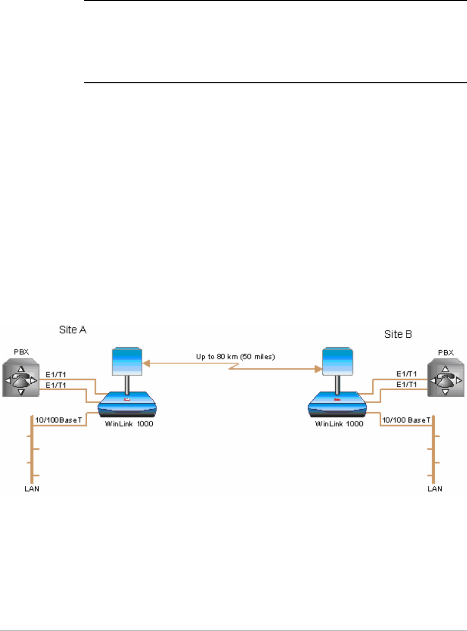
link and supports ranges of up to 80 km (50 miles).
Application
Figure 1-1
illustrates a typical point-to-point application of two
WinLink 1000 units.
Figure 1-1. Typical Application
Overview 1-1

Chapter 1 Introduction WinLink 1000 Installation and Operation Manual
Features
Wireless Link
WinLink 1000 delivers up to 48 Mbps data rate for Ethernet and E1/T1
traffic. The system supports a variety of spectrum bands and can be
configured to operate in any channel on the band with a carrier step
resolution of 5 MHz.
WinLink 1000 operation complies with ETSI, CSA and the FCC 47CFR
Part 15 and subpart C and E requirements.
WinLink 1000 employs Time Division Duplex (TDD) transmission. This
technology simplifies the installation and configuration procedure.
There is no need to plan and to allocate separate channels for the
uplink and downlink data streams.
Operation over 2.4GHz, 4.9 GHz, and 5.x GHz bands is not affected by
harsh weather conditions, such as fog, heavy rain etc.
LAN Interface
The WinLink 1000 LAN port provides 10/100BaseT interfaces with auto
negotiation and transparent VLAN support. Traffic handling is provided
by a MAC-level self-learning bridge.
TDM Interface
The WinLink 1000 TDM interface accepts E1 or T1 traffic, supporting
the following:
• Unframed operation (E1 and T1)
• AMI and B8ZS zero suppression (T1).
Management
WinLink 1000 has full local and remote management capabilities. The
user-friendly SNMP-based management tool provides full end-to-end
configuration, event log and performance monitoring capabilities.
Diagnostics and Performance Monitoring
WinLink 1000 supports activating local and remote loopbacks on E1/T1
links.
1-2 Overview

WinLink 1000 Installation and Operation Manual Chapter 1 Introduction
WinLink 1000 constantly monitors the data transmission process,
evaluates received signal strength, and signal quality. It also monitors
received traffic and frame rate (FPS) for local and remote units.
Optional External Antenna
WinLink 1000 supports configuration of an external antennae. In this
configuration, the radio supplies an N-type connector that connects
through a coax cable to the external antenna.
An external antenna can extend the range of the link, and in some
cases, it might help to reduce environmental interferences. Various
external antennae are available for the WinLink 1000 operating
frequencies.
For example, an optional flat panel 28 dBi external antenna increases
the operation range of WinLink 1000 up to 80 km (50 miles).
Overview 1-3
Chapter 1 Introduction WinLink 1000 Installation and Operation Manual
1.2 Physical Description
WinLink 1000 system consists of an Outdoor Unit (ODU) and an Indoor
Unit (IDU).
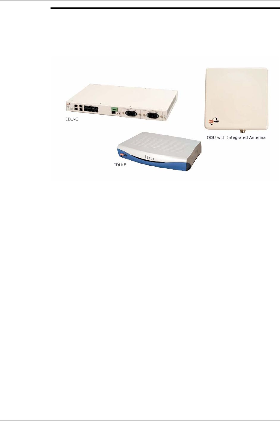
Figure 1-2
illustrates a WinLink 1000 unit assembly.
Figure 1-2. WinLink 1000 Units
IDU-E
The IDU-E front panel includes five LEDs that display the status of
E1/T1 and LAN, wireless link, self-test results, ODU-to-IDU link, and
power status. For a detailed description of the front panel LEDs, see
Chapter 4
.
The rear panel of the indoor unit (IDU) includes the power, WAN, LAN
and E1/T1, and ODU connectors. The rear panel LEDs are described in
Chapter 4
, and the wiring specifications detailed in
Appendix A
.
IDU-C
The IDU-C front panel includes four LEDs that display the status of
E1/T1and, wireless link, self-test results, and ODU-to-IDU link. For a
detailed description of the front panel LEDs, see
Chapter 4
.
1-4 Physical Description

WinLink 1000 Installation and Operation Manual Chapter 1 Introduction
Technical Specifications
Air-Interface
Technology
OFDM
Frequency Band
2.400–2.4835 GHz FCC/ETSI
2.416–2.4835 GHz (Israel)
4.940-4.990 GHz FCC
5.250–5.350 GHz FCC
5.470–5.725 GHz FCC/ETSI
5.725–5.850 GHz FCC
Range
Up to 80 km (50 miles)
Duplexing Method
Time Division Duplex (TDD)
Capacity
Configurable up to 48 Mbps
Modulation
OFDM - BPSK, QPSK, 16QAM, 64QAM
Channel setting
Resolution
5 MHz
Transmitter Power
17 dBm max, for 4.9GHz 12.8 dBm max.
(Blocked by product SW and can not be
changed).
ODU Installation
Mast or wall mounting
LAN Interface
PHY IF
Up to 2 x 10/100BaseT, auto-sensing
Framing/Coding
IEEE 802.3/U
Bridging
Self-learning, up to 2000 MAC addresses
Line Impedance
100Ω
VLAN Support
Transparent
Connector
RJ-45
E1 Interface
Data Rate
1, 2, 4 x E1
Unframed (Transparent) 2.048 MHz
Line Interface
HDB3
Connector
RJ-45
T1 Interface
Data Rate
1, 2, 4 x T1
Unframed (Transparent) 1.544 MHz
Physical Description 1-5

Chapter 1 Introduction WinLink 1000 Installation and Operation Manual
Line Interface
AMI, B8ZS
Connector
RJ-45
Indicators
PWR (green)
Power status
IDU (green)
IDU status
ODU (green/red)
ODU-to-IDU link status
AIR I/F (green/red)
Air Interface status
SERVICE (green/red)
E1/T1 signal status
Power
Source IDU-E
100–240 VAC -48VDC via external AC/DC
converter
Source IDU-C
100–240 VAC via cable & plug, or -24VDC or
-48VDC from rack
Power Consumption
10W max – IDU-E and ODU
14W max – IDU-C and ODU
Connector
2-pin for IDU-E
IDU-C:
DC ver: 3-pin terminal block
AC ver: 3-prong plug
Physical Outdoor Unit (ODU) with integrated antenna
Height
305 mm / 12 in
Width
305 mm / 12 in
Depth
58 mm / 2.3 in
Weight
3.3 kg / 7.2 lb
Indoor Unit
IDU-E IDU-C
Height
44 mm / 1.7 in (1U) 43 mm / 1.7 in
Width
237 mm / 9.3 in 297 mm / 11.5 in
Depth
170 mm / 6.7 in 450 mm / 17.7 in
Weight
0.58 kg / 1.4 lb 1.5 kg / 3.3 lb
Environment
Outdoor Unit (ODU)
Enclosure
All-weather case
1-6 Physical Description

WinLink 1000 Installation and Operation Manual Chapter 1 Introduction
Temperature
-35°C to 60°C/-31°F to 140°F
Indoor Unit (IDU-E
and IDU-C)
Temperature
-5°C to 45°C/23°F to 113°F
Humidity
Up to 90%, non-condensing
Antenna
Characteristics
2.400-
2.4835 GHz
4.940-
4.990GHz
5.250-
5.350GHz
5.4470-
5.725GHz
5.725-
5.850GHz
Integrated Antenna 1 ft
Gain 16dBi 22dBi 22dBi 22dBi
Beam width 20° N/A 9° 9° 9°
Polarization Linear Linear Linear Linear
External antenna 1 ft
Gain 21 dbi 22 dBi 22 dBi 22 dBi
Beam width N/A 9° 4.5° 4.5° 4.5°
Polarization Linear Linear Linear Linear
External Antenna 2 ft
Gain 24dBi 27 dbi 28dBi 28dBi 28dBi
Beam width 8° 4.5° 4.5° 4.5° 4.5°
Polarization Linear Linear Linear Linear Linear
External Antenna 3 ft
Gain 32 dBi 32.5 dBi
Beam width N/A N/A 4.5° N/A 4.5°
Polarization Linear Linear
* Antennaes with higher gains are available
Physical Description 1-7

WinLink 1000 System 2-1
Chapter 2
Installation and Setup
This chapter describes installation and setup procedures for WinLink
1000 system.
After installing the unit, refer to
Chapter 3
for configuration
instructions and
Chapter 4
for operation instructions.
In case a problem is encountered, refer to
Chapter 5
for test and
diagnostic instructions.
Internal settings, adjustment, maintenance, and repairs may be
performed only by a skilled technician who is aware of the hazards
involved.
Always observe standard safety precautions during installation,
operation, and maintenance of this product.
WinLink 1000 has three types of products:
•
Auto channel selection is not supported–Previous or Future release.
•
Auto channel selection supported–User can enable/disable auto
channel configuration.
•
DFS–Auto channel is mandatory.
2.1 WinLink 1000 System
WinLink 1000 system comprises the following units:
• Outdoor Unit (ODU): The ODU has 2 configurations: ODU with
integrated antenna and ODU with N-Type connector for connection
to an external antenna. Both ODU types have the same interface to
the IDU. The ODU with integrated antenna has an enclosed
aluminum frame with a front sealed plastic cover, containing an
integrated transceiver with an antenna, RF module, modem and
standard interfaces.
Warning
No
te

Chapter 2 Installation and Setup WinLink 1000 Installation and Operation Manual
2-2 Package Contents
ODU includes a power connector that receives -48 VDC and a RJ-45
for Ethernet traffic from the indoor unit (IDU).
The ODU is attached to a mast using a special mounting kit, which
is supplied with the unit.
• Indoor Unit (IDU): There are two types of IDU cages. IDU-E that is a
plastic box of ½ x 19 in. and IDU-C that is based on a metal 19in.
box address the carrier-class applications. IDU is the interface unit
between the ODU and the user. It converts 100–240 VAC to
-48VDC, and feeds the ODU by it. The IDU does not store any
configuration data. Therefore, there is no need for additional
configuration of the WinLink 1000 system when replacing an IDU.
2.2 Site Requirements and Prerequisites
For the IDU, allow at least 90 cm (36 in) of frontal clearance for
operating and maintenance accessibility. Allow at least 10 cm (4 in)
clearance at the rear of the unit for signal lines and interface cables.
The ambient operating temperature should be –45°C to 60°C/-49°F to
140°F (ODU), or -5°C to 45°C/23°F to 113°F (IDU) at a relative humidity
of up to 90%, non-condensing.
Before starting the installation, use the
Link Budget Calculator
utility to
calculate expected performance of the link. You can vary parameter
inputs to the calculator to determine the optimum system
configuration. The utility is described in
Appendix C
.
2.3 Package Contents
The WinLink 1000 packages include the following items:
ODU Package Containing:
• ODU
• Mast/Wall mounting kit plus mounting instructions
• WinLink 1000 Manager installation CD
• Spare RJ-45 Connector
IDU-E Package Contents:
• IDU-E

WinLink 1000 Installation and Operation Manual Chapter 2 Installation and Setup
Installation and Setup 2-3
• 110V/240V adaptor
• IDU wall-mounting drilling template
• Spare RJ-45 connector
(Optional) IDU-C Package Contents:
• IDU-C
• For AC model, 110v/240 VAC with 3-prong connector cable
• For DC model, –24VDC or -48 VDC with 3-pin terminal block
connector (green)
• IDU standard 1-U, 19” carrier rack
• Spare RJ-45 connector
External antenna (if ordered)
ODU/IDU Cable at length ordered (optional)
2.4 Installation and Setup
Physical installation of the WinLink 1000 system installation includes
the following steps:
1. Installing ODU at both sites of the link.
2. Installing ODU cable and connecting ODU to IDU at both sites.
3. Connecting power.
4. Installing the management program on the network management
station.
5. Running the Installation wizard from the management program.
6. Aligning the ODUs.
7. Connecting user equipment to the local and remote IDUs.
Chapter 2 Installation and Setup WinLink 1000 Installation and Operation Manual
2-4 Installation and Setup
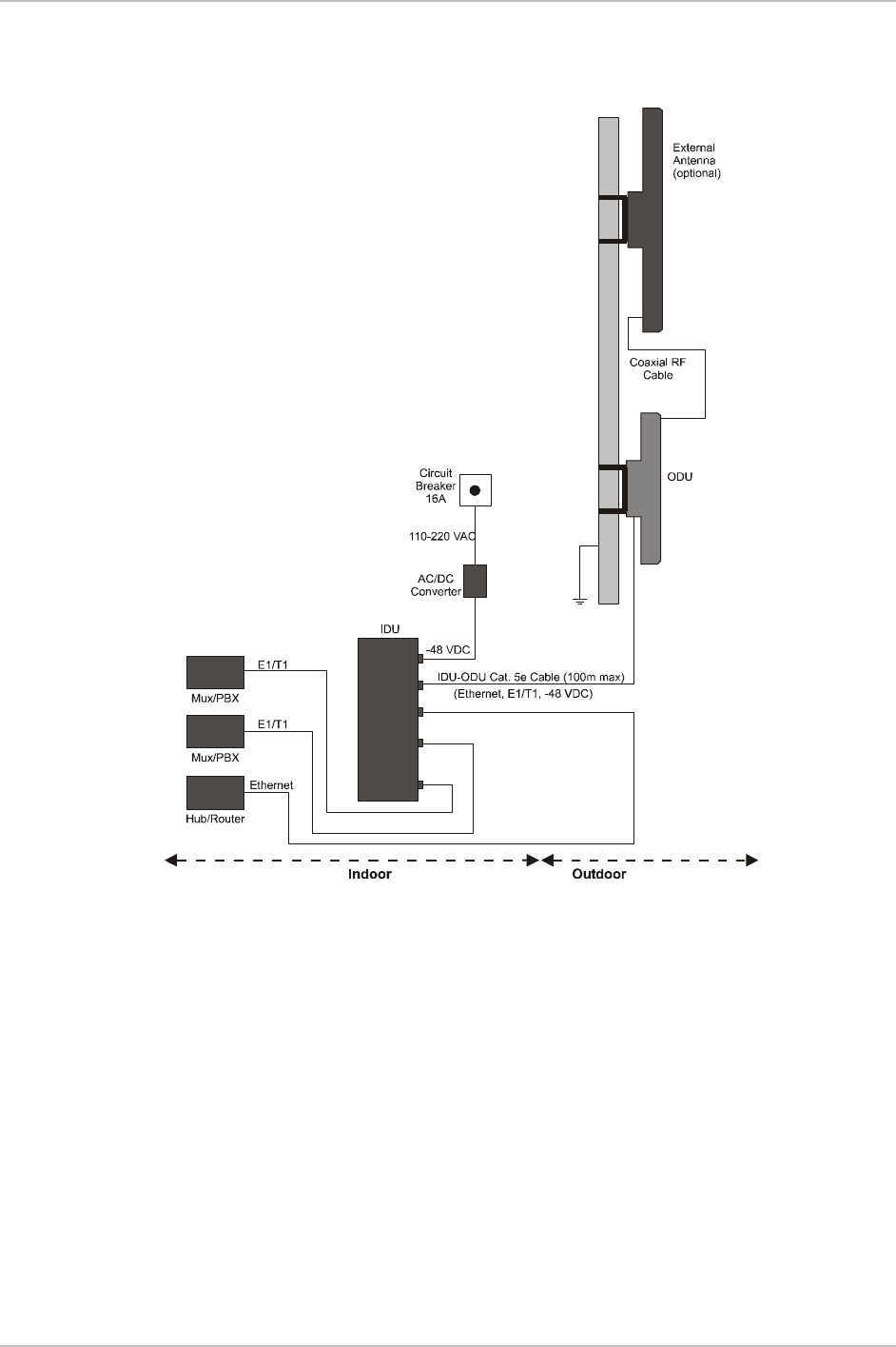
Figure 2-1
illustrates a typical installation of WinLink 1000 with an
external antenna.
Figure 2-1. Typical Installation Diagram
Mounting the ODU
The ODU is the transmitting and receiving element of the WinLink 1000
system. The ODU can be mounted on a mast or a wall. In both
installations, the supplied mounting kit is used to secure the ODU.
Appendix B
describes the mast/wall installation instructions.
A WinLink 1000 link operates in pairs of two WinLink 1000 systems
with the same configuration. Both systems must be installed, and the
antennas of the outdoor units must be aligned for maximum
throughput.

WinLink 1000 Installation and Operation Manual Chapter 2 Installation and Setup
Installation and Setup 2-5
Prior to connecting cables to the ODU, the protective earth terminal
(screw) of the ODU must be connected to an external protective ground
conductor or to a grounded mast.
Only a qualified person using the proper safety equipment should
climb the antenna mast. Only trained professional installers should be
used when installing or dismantling ODUs and masts.
Î To mount the ODU:
1. Verify that the ODU mounting brackets are properly grounded.
2. Attach the ODU unit to the mast. Refer to
Appendix B
for the ODU
mounting instructions.
3. Connect the ground cable to the chassis point on the ODU.
4. Attach the ODU cable to the RJ-45 connector. Refer to
Appendix A
for the connector pinout.
5. Secure the cables to the mast or brackets using provided UV-rated
cable ties.
6. Repeat the procedure at the remote site.
Do not tightly secure the ODU to its mounting brackets, until the
alignment process of the antenna is complete.
When installing the ODU, it is important to check that there are no
direct obstructions in front of the ODU or interference from man-made
obstacles.
Connecting the ODU to the IDU
The ODU cable conducts all the user traffic between the IDU and the
ODU. The ODU cable also provides -48 VDC supply to the ODU. The
maximum length for one leg of the ODU cable is 100m (328 ft) in
accordance with10/100BaseT standards.
ODU cable is supplied pre-assembled with RJ-45 connectors, at the
length specified when ordering. If the ODU cable was not ordered, use
Cat. 5e shielded cable, the wiring specifications are given in
Appendix A
.
1. Route the cable from the ODU location into the building, leaving
some spare. Secure the cable along its path.
Warning
Note
Chapter 2 Installation and Setup WinLink 1000 Installation and Operation Manual
2-6 Installation and Setup
2. Connect the ODU cable to the RJ-45 connector on the IDU panel
designated WAN.
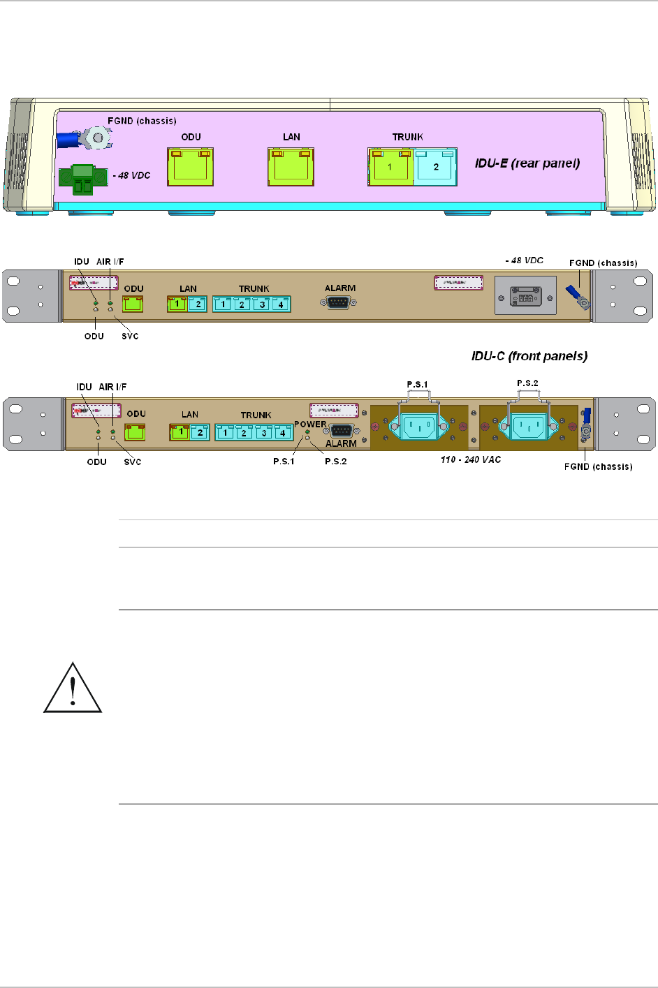
Figure 2-2
illustrates a typical panel of the IDU-E
and IDU-C.
Figure 2-2. IDUs connector panels
Other models may have a different configuration for these panels.
Connecting the Power
Before connecting any cable, the protective earth terminals of the
AC/DC power must be connected to the protective ground conductor
of the mains power cord. (Applies to both IDU models.) If you are using
an extension cord (power cable) make sure it is grounded as well.
Any interruption of the protective (grounding) conductor (inside or
outside the instrument) or disconnecting of the protective earth
terminal can make this unit dangerous. Intentional interruption is
prohibited.
Power is supplied to WinLink 1000 via an external AC/DC converter,
which receives power from 110–240 VAC source and converts it to
-24VDC or -48 VDC.
Warning
Note

WinLink 1000 Installation and Operation Manual Chapter 2 Installation and Setup
Installation and Setup 2-7
Î To connect the power IDU-E:
1. Connect the 2-pin plug of the AC/DC converter to the 2-pin DC
power connector on the IDU-E rear panel.
2. Connect the AC/DC converter 3-prong plug to mains outlet.
Î To connect the power for IDU-C:
• For AC power model, connect the AC cable 3-prong plug to mains
outlet.
• For DC power model, connect to DC supply on the rack (male
connector for the terminal block is included).
Installing WinLink 1000 Management Software
WinLink 1000 management application is distributed on CD-ROM as an
executable file. The application has the following PC requirements:
• Memory: 128 MB RAM
• Disk: 1 GB free hard disk space
• Processor: Pentium 3 or higher
• Network: 10/100BaseT NIC
• Graphics: Card and Monitor that supports 1024×768 screen
resolution with 16 bit color
• Operating system: Windows 2000/XP
• Microsoft Explorer 5.01 or later.
Î To install the WinLink 1000 management program:
1. Insert the CD-ROM into your CD-ROM drive.
2. If the installation does not start automatically, run WinLink.exe
from the CD-ROM drive.
3. Follow the on screen instructions of the installation wizard to
complete setup of the WinLink 1000 Management program in the
desired location.
Î To perform initial setup:
1. Power up the site A's IDU (see
Connecting the Power
on page
2-6
).
Wait about 1 minute.
2. Power up the site B IDU.
Chapter 2 Installation and Setup WinLink 1000 Installation and Operation Manual
2-8 Installation and Setup
3. Connect the management station to the LAN.
Any PC running the WinLink 1000 Management application can be used
to configure WinLink 1000 units.
Î To start WinLink manager:
1. From the Start menu, point to Programs, point to WinLInk Manager,
and then click WinLink Manager.
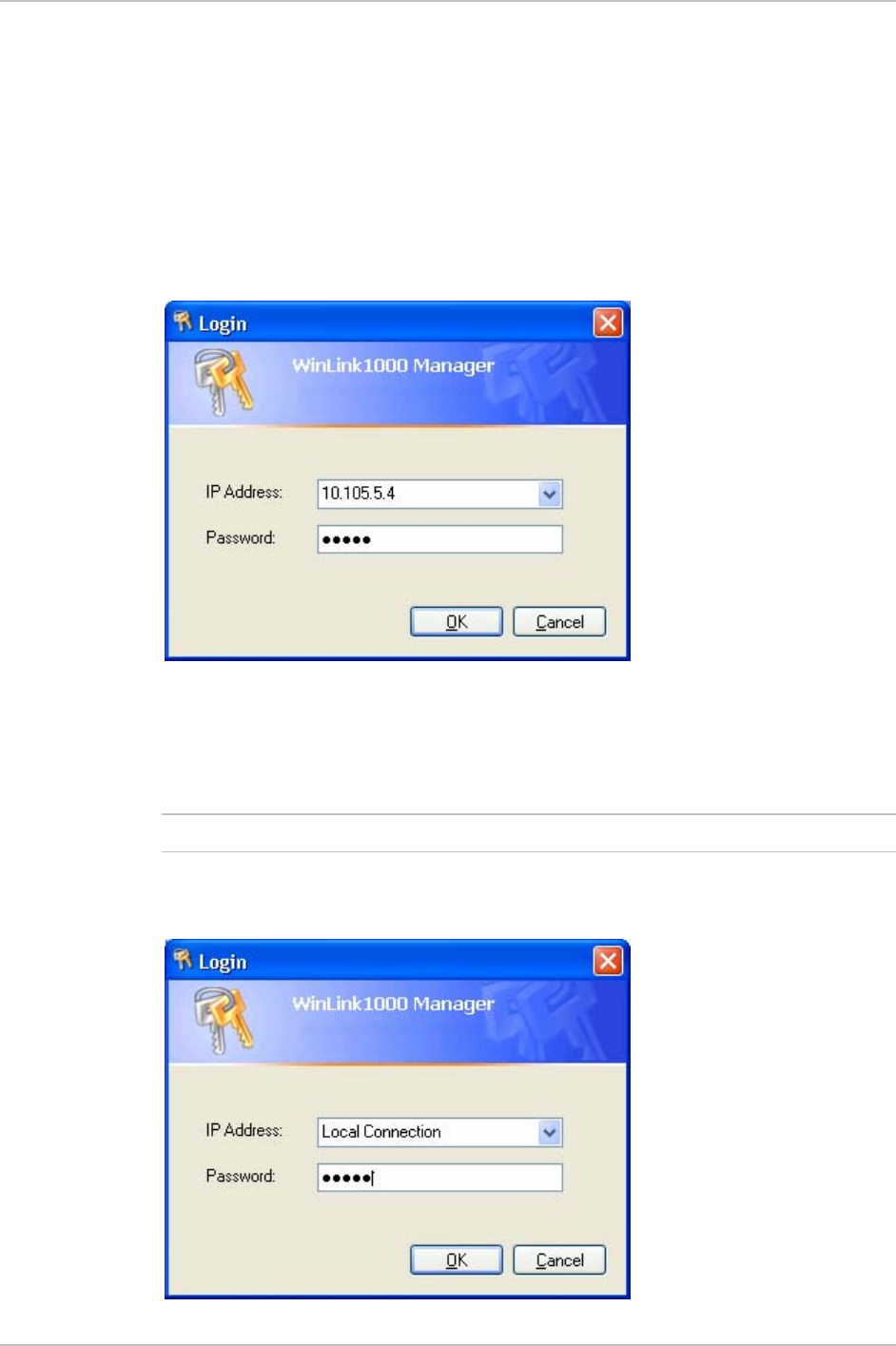
The password/IP request dialog appears.
Figure 2-3. Login Screen
2. Select the suitable option for the IP Address field:
Enter the IP address of the ODU —
default value 10.0.0.120
.
The IP address is defined later during link configuration.
(optional) If user is connected directly to the IDU LAN port, use
the adjacent list arrow to select Local Connection.
Note
WinLink 1000 Installation and Operation Manual Chapter 2 Installation and Setup
Installation and Setup 2-9
Figure 2-4. Login vial Local Connection Screen
3. Enter the password
Default password –
admin
(see Chapter 4 for
Changing the
Password
)
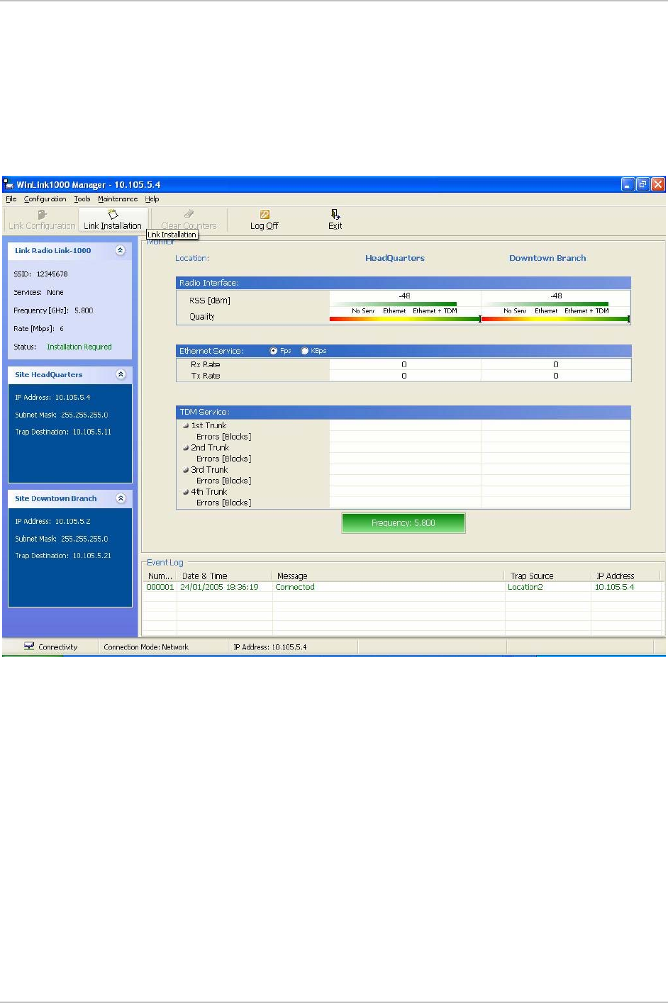
The WinLink Manager Main menu is displayed (see
Figure 2-5
).
Figure 2-5. Main Menu
Aligning the WinLink 1000 ODUs
Perform the WinLink 1000 ODU alignment using the Buzzers located
inside the ODUs. Alignment of a WinLink 1000 link must be performed
by two people simultaneously, at site A and at site B.
Î To align the ODUs via ODU Buzzer:
1. Verify that power is connected to the IDUs at both sites.
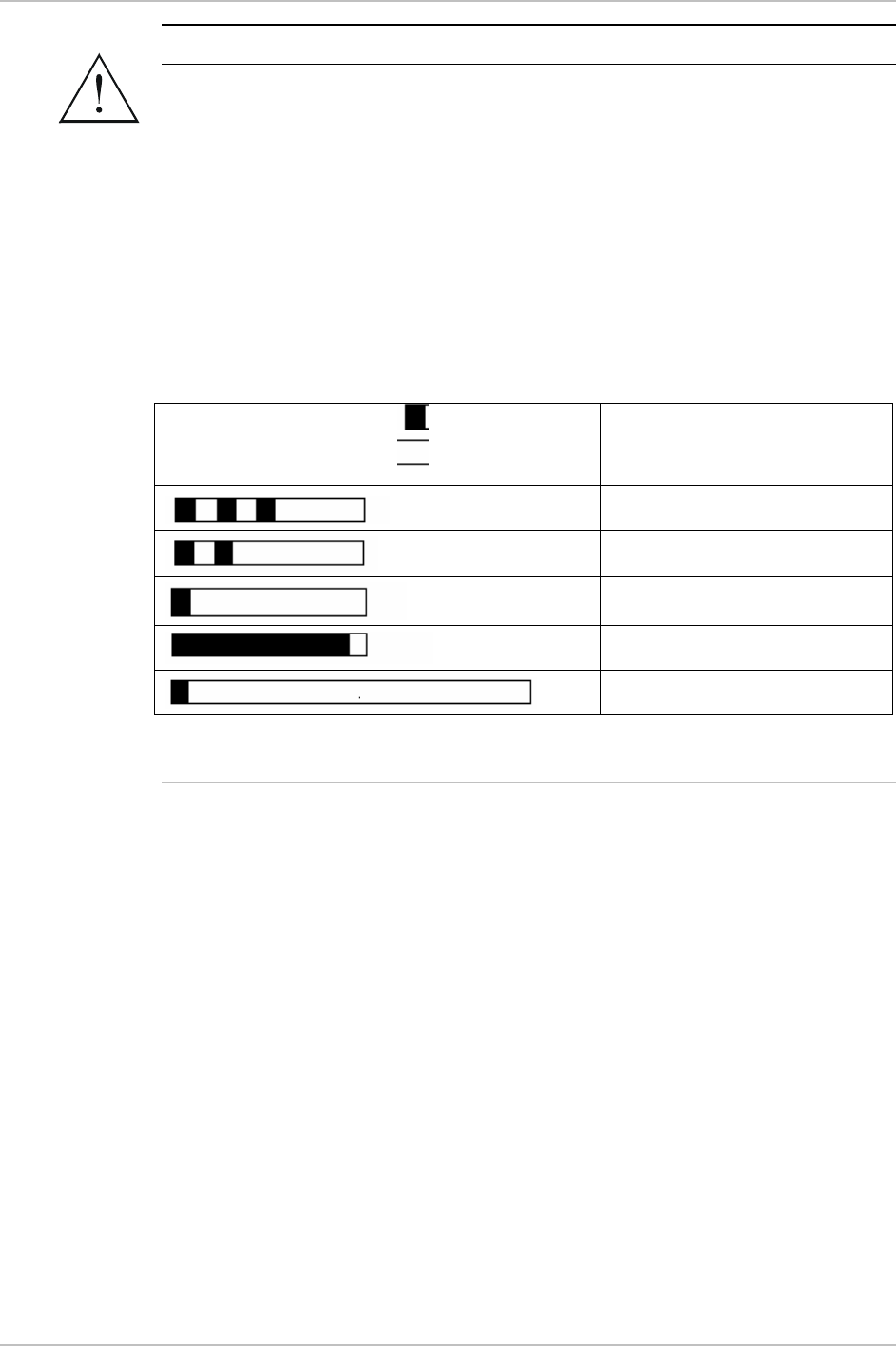
Chapter 2 Installation and Setup WinLink 1000 Installation and Operation Manual
2-10 Installation and Setup
Do not stand in front of a live radio terminal.
2. Align the site A ODU in the direction of the site B ODU.
3. Align the site B ODU in the direction of the site A ODU
4. Alternating between each site, turn each ODU slowly while listening
to the buzzer beep sequence for the Best Signal sound, until
optimal alignment is achieved.
5. Secure the site A and site B ODUs to the mast/wall.
6. Monitor the link quality for about 15 minutes to verify stability.
Buzzer Sequence
=buzzer on
=buzzer off
Description
Best Signal so far
Signal quality increased
No change in signal
Signal quality decreased
No air link
Figure 2-6. Beeper Sequence for ODU Alignment
Installing the Link
Installation and definition of all parameters are applied to both sides of
the link.
Î To install the link:
1. Verify that the management station is properly connected to the
same LAN as the IDU, and the WinLink Manager application is
running.
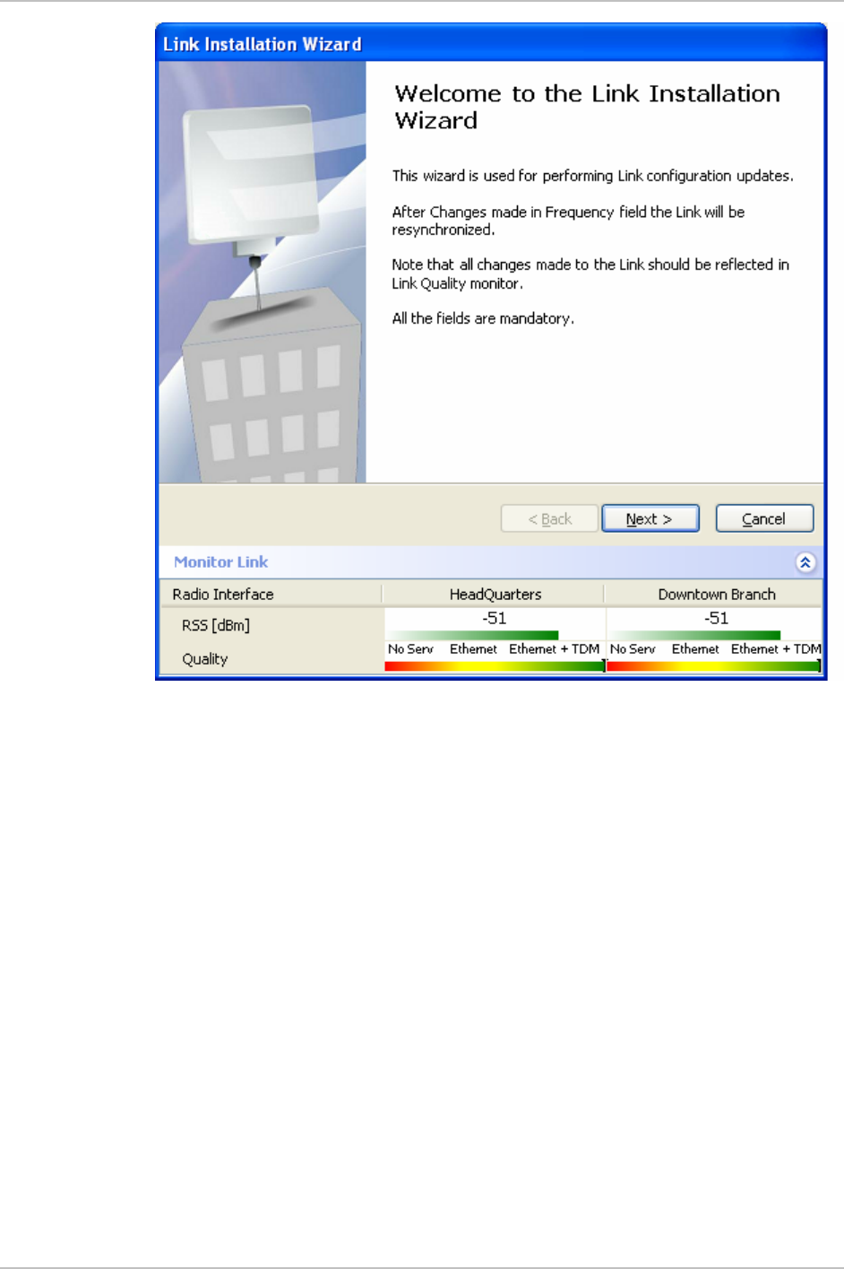
2. In the toolbar, click the Link Installation button.
The Installation wizard opens, (see
Figure 2-7
).
Warning
Chapter 2 Installation and Setup WinLink 1000 Installation and Operation Manual
2-12 Installation and Setup
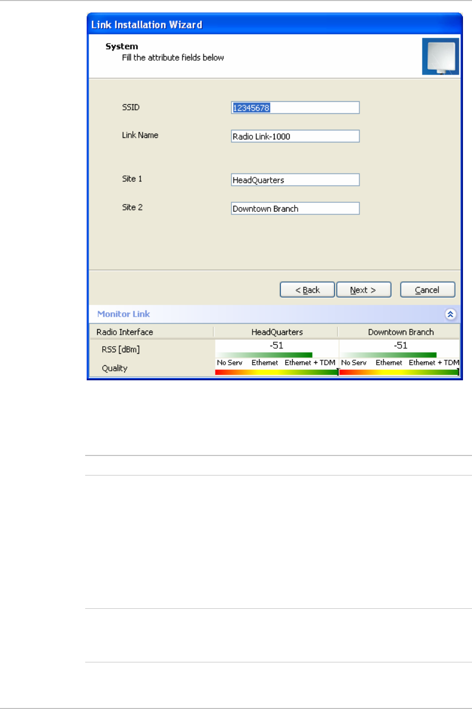
Figure 2-8. Installation Wizard, System dialog box
4. Enter a SSID (System ID) minimum of eight characters. The ID is
initially factory set.
•
Both sites of a link must always have the same number
5. Enter Link name for the link identification.
6. Enter a name for site 1.
7. Enter a name for site 2.
8. Click Next.
The Channel Select dialog box appears (see
Figure 2-9
for
previous releases).
For release 1.1.6 and above refer to Figure 2-10, page 2-14.
For 5.4GHz DFS according to ETSI standard, refer to Figure 2-11 on
page 2-15.
Notes
Note
WinLink 1000 Installation and Operation Manual Chapter 2 Installation and Setup
Installation and Setup 2-13
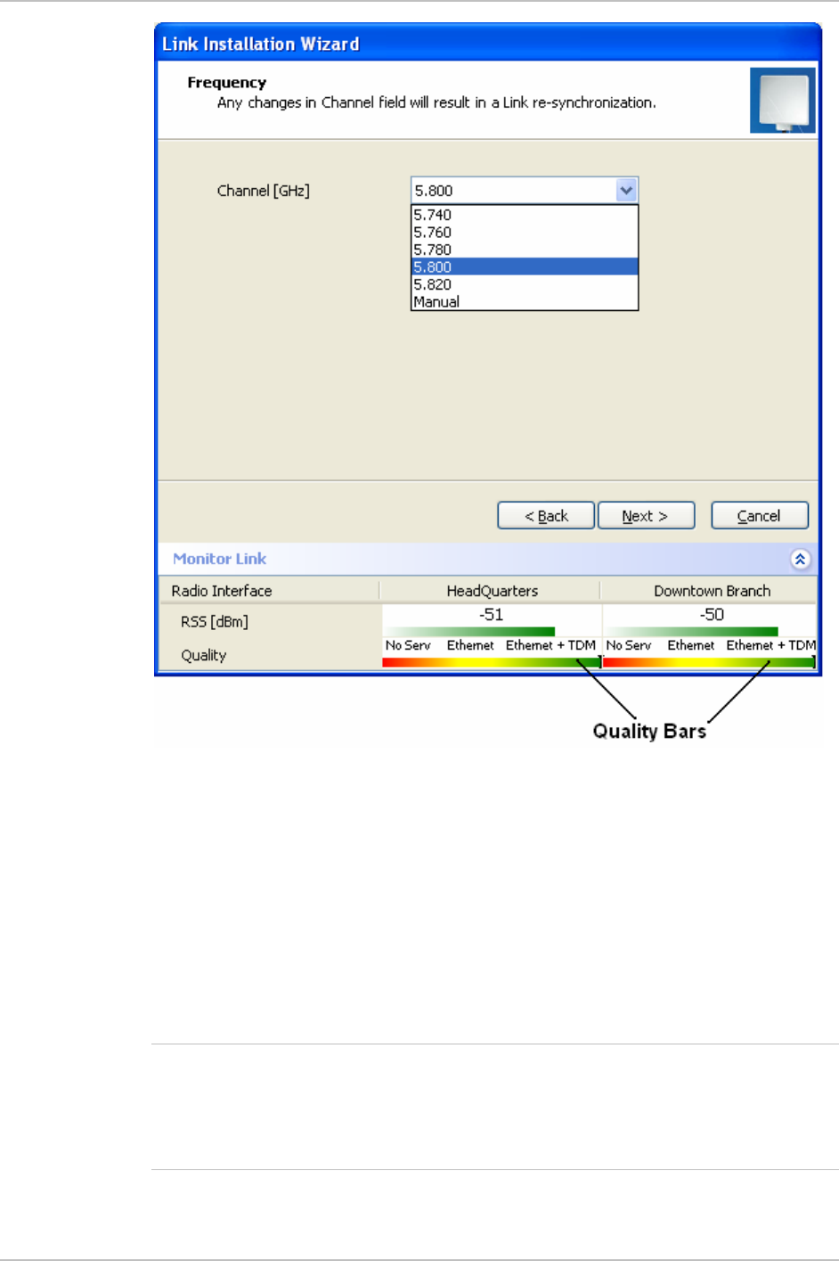
Figure 2-9. Installation Wizard, Channel Select dialog box
9. Select the required operating channel.
The pull down list shows the ISM frequencies available.
The Manual option allows you a User defined channel, within the
system frequency band.
Selecting a new channel causes the system quality to change. The
quality bar shows the adjustment until the system finds the best
quality link.
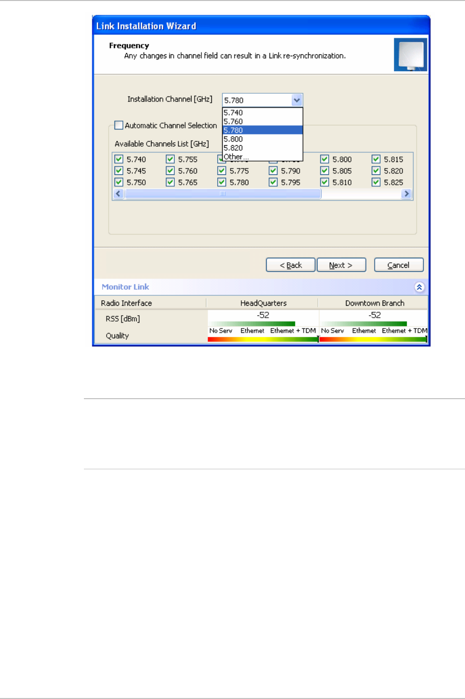
The installation of products that support automatic channel selection is
performed in a user defined channel, called the installation channel.
After selecting the channel, the list of channels for automatic channel
selection can be modified.
Note
Chapter 2 Installation and Setup WinLink 1000 Installation and Operation Manual
2-14 Installation and Setup
Figure 2-10. Installation Wizard, Channel Select dialog box (Automatic
Channel Select enabled)
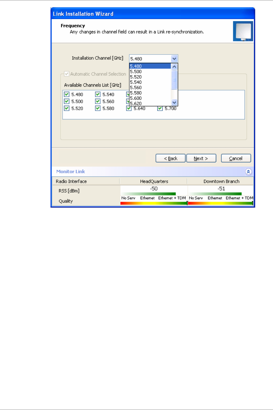
This feature is for the 5.4GHz ETSI version product only.
DFS/TPC–Dynamic Frequency Select/Transmit Power control: according
to ETSI standard for the unlicensed band that eliminates interruption of
the wireless data equipment to the radar service.
Note
WinLink 1000 Installation and Operation Manual Chapter 2 Installation and Setup
Installation and Setup 2-15
Figure 2-11. Installation Wizard, Channel Select dialog box (Supporting DFS,
ETSI standard requirement)
10. Click Next.
The Rate Select dialog box appears (see
Figure 2-12
)
Table 1-1
lists throughput rates and capacities.
Chapter 2 Installation and Setup WinLink 1000 Installation and Operation Manual
2-16 Installation and Setup
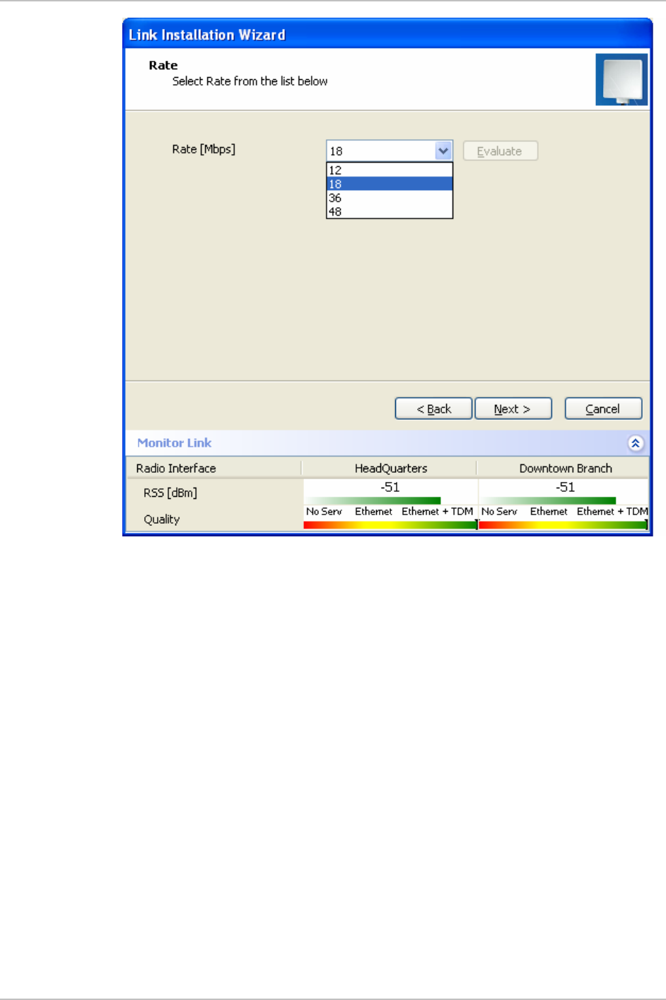
Figure 2-12. Installation Wizard, Rates dialog box
11. Select a suitable air interface rate according to the services
required.
12. Click Evaluate.
13. A question box pops up, asking if you want to re-evaluate the link.
Click Yes to change the rate No to keep the existing rate.
Selecting a new rate causes the system quality to change. The
quality bar shows the adjustment until the system finds the best
quality link.
14. Click Next.
The Service Parameters dialog box appears (see
Figure 2-13
).
WinLink 1000 Installation and Operation Manual Chapter 2 Installation and Setup
Installation and Setup 2-17
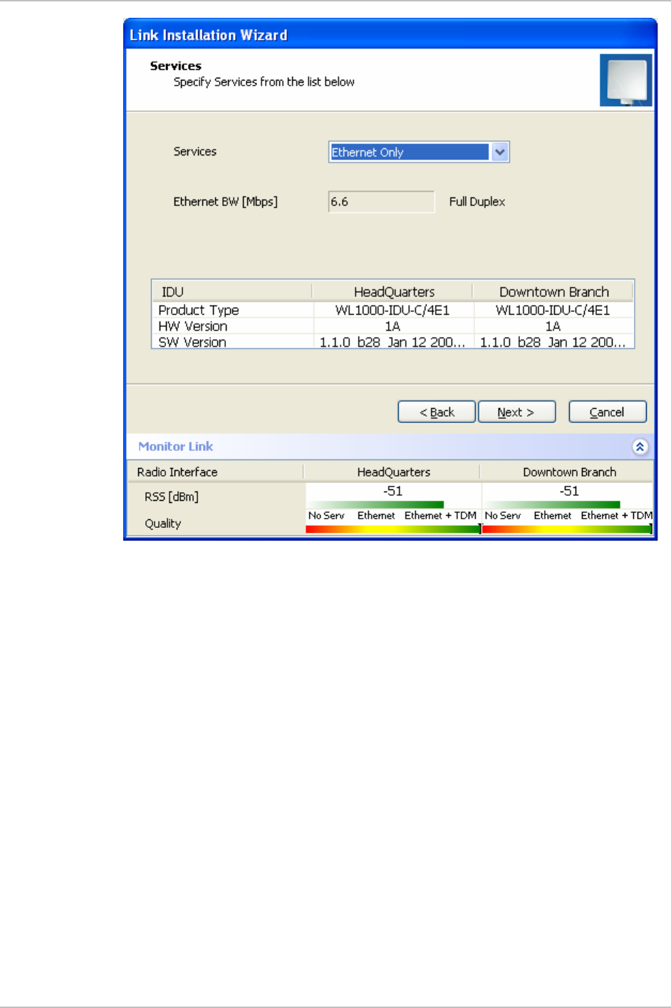
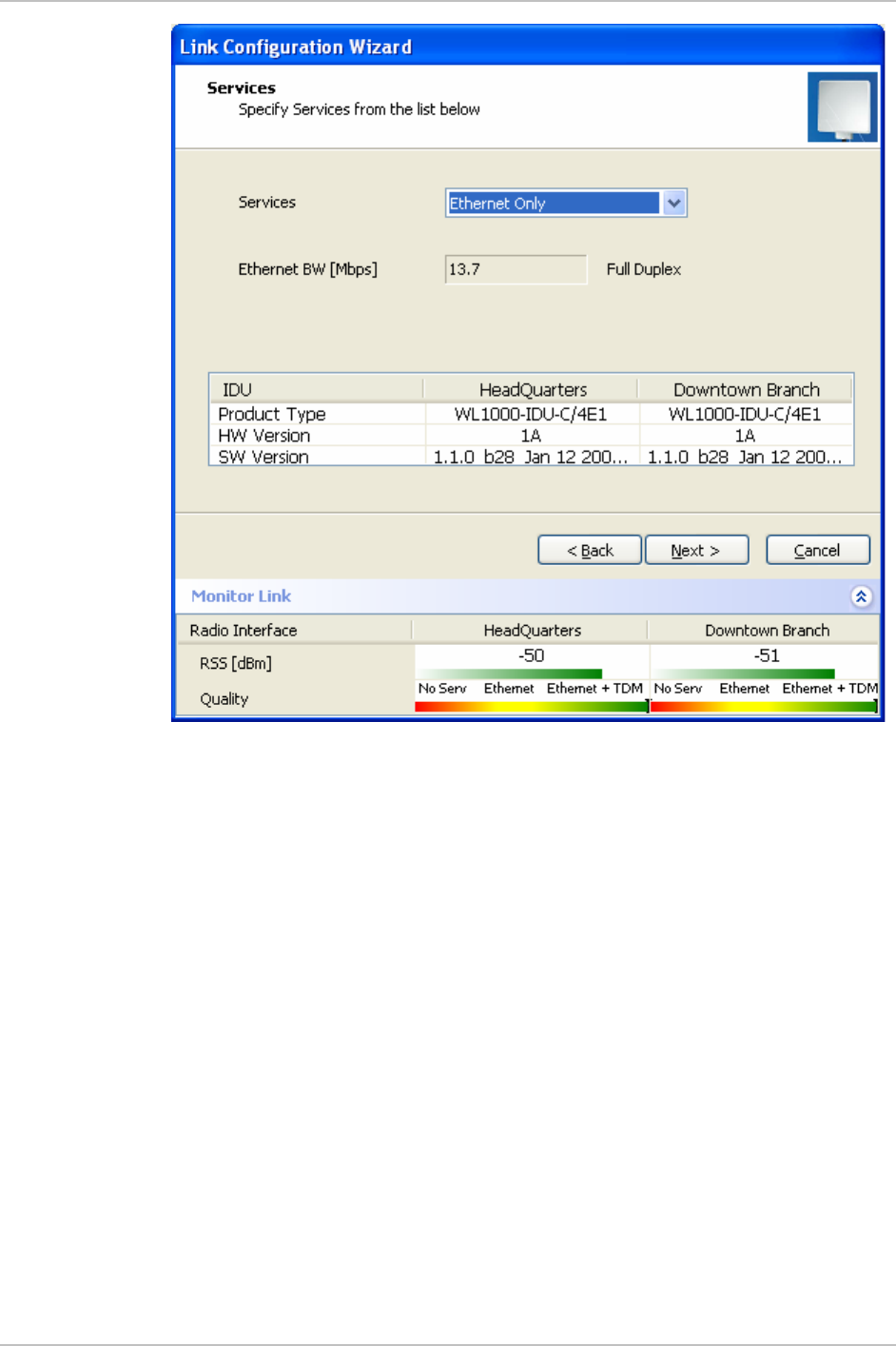
Figure 2-13. Installation Wizard, Services dialog box
15. In the Service dialog box, select one of the following:
E1/T1 – Select the E1/T1 field, if you intend to transmit E1/T1
data and Ethernet data.
The Ethernet BW field shows the remaining bandwidth in Mbps
available for Ethernet. The available bandwidth depends on the
number of E1/T1 ports selected.
Select the Ethernet field, if you intend to transmit Ethernet data
only
16. Click Next.
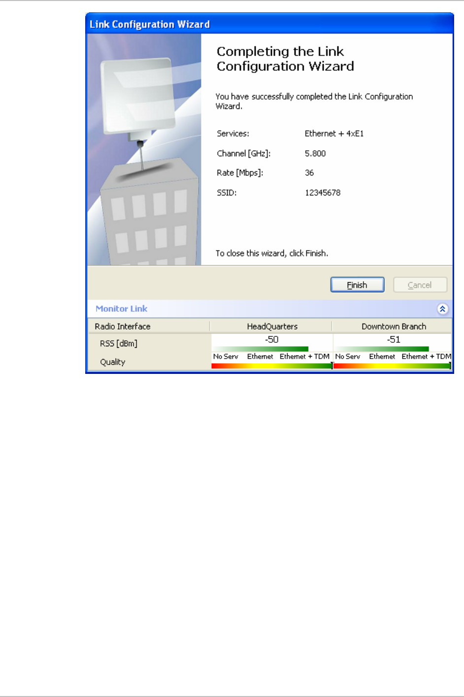
The Finish screen appears (see
Figure 2-14
).
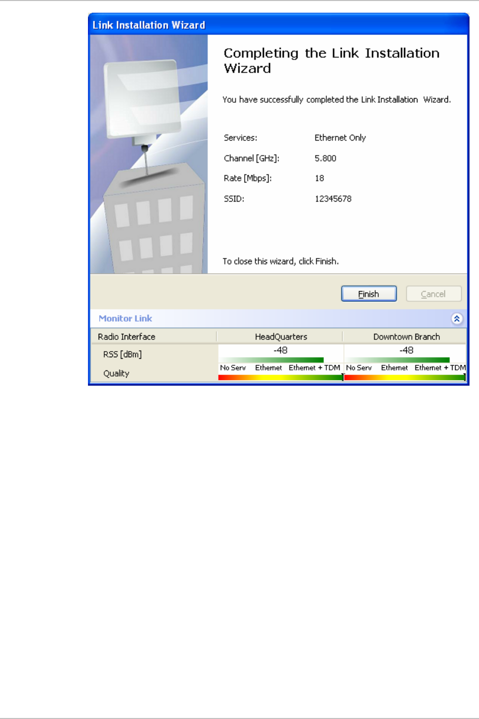
The Finish screen shows a summary of the link configuration,
the alignment is complete.
Chapter 2 Installation and Setup WinLink 1000 Installation and Operation Manual
2-18 Installation and Setup
Figure 2-14. Installation Wizard, Finish Screen
17. Click Finish to complete the installation wizard.
When the wireless link is established between the site A and
site B units, the Link Status indication bar of the Main menu is
within the green area.
18. Verify that the radio signal strength (RSS) in the Main menu is
according to expected results.
Connecting the User Equipment
The IDU-E is a standalone desktop, wall-mounted unit. This unit has
both front and rear panel connections.
The optional IDU-C is a standalone rack mounted unit. This unit has
only front panel connections.
Figure 2-2
illustrates the typical panels of the IDUs.

WinLink 1000 Installation and Operation Manual Chapter 2 Installation and Setup
Installation and Setup 2-19
Î To connect user equipment to the IDU:
1. Connect user E1/T1 traffic to the appropriate IDU panel RJ-45 port
designated Trunk. Refer to
Appendix A
for the connector pinout.
2. Connect user hub/router or any other compatible device to the
appropriate IDU panel RJ-45 port designated LAN. Refer to
Appendix A
for the connector pinout.
IDU-C has an integrated LAN switch that provides 2 ports of
10/100BaseT. The integrated LAN switch does not support spanning
tree.
The two LAN ports can be connected to two separate LAN segments,
but connection of both LAN ports to the same LAN segment will create
a loop that floods the network. Therefore, this configuration is
prohibited.
Use a straight cable for router connection.
Note
Note

Chapter 3
Configuration
This chapter describes configuration procedures that are performed
after the link has been installed, synchronized, and the link
configuration has been performed by wizard.
WinLink 1000 has three types of products:
Note
•
Auto channel selection is not supported–Previous or Future release.
•
Auto channel selection supported–User can enable/disable auto
channel configuration.
•
DFS–Auto channel is mandatory.
3.1 Performing Configuration of WinLink 1000
After installing the link, the system configuration can be altered.
Performing Configuration of WinLink 1000 3-1
Chapter 3 Configuration WinLink 1000 Installation and Operation Manual
Installation and definition of all parameters are applied to both sides of
the link.
Note
Figure 3-1. WinLink Manager Main Menu
Î To change general parameters:
1. In the Main menu, click the Link Configuration button.
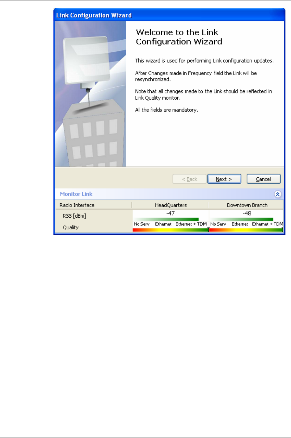
2. The Configuration Wizard opens.
The wizard is used to make configuration changes.
3-2 Performing Configuration of WinLink 1000
Chapter 3 Configuration WinLink 1000 Installation and Operation Manual
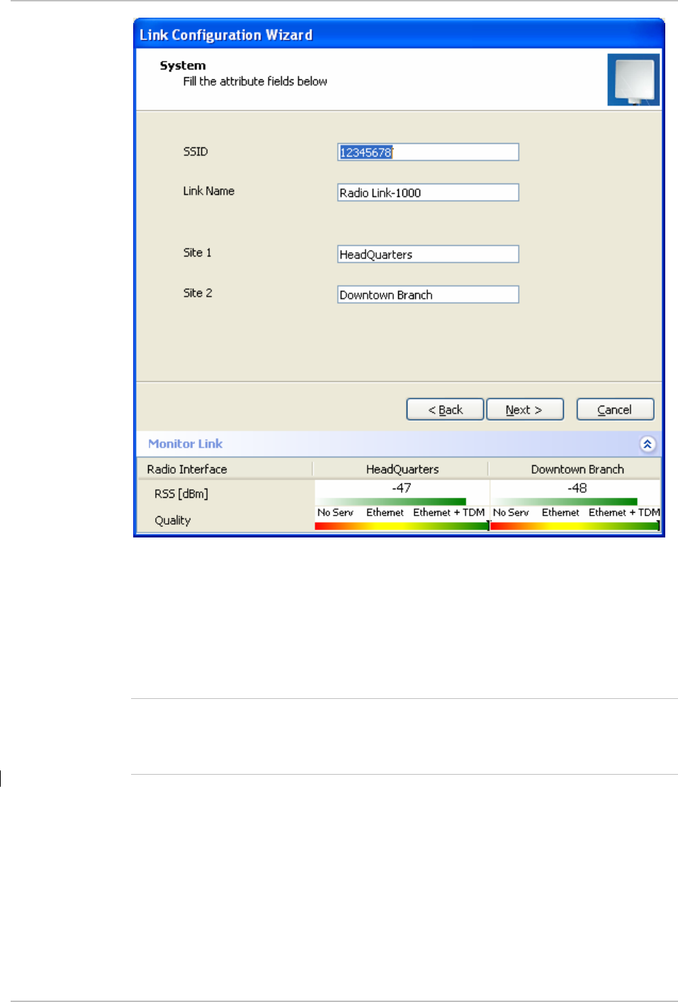
Figure 3-3. Link Configuration, System dialog box
5. In the System dialog box, enter the new data to for the link. All
fields with a white background can be edited.
6. Click Next.
The Frequency dialog box appears (see
Figure 3-4
).
For releases 1.1.6 and above, refer to Figure 3-6 on page 3-6.
For 5.4GHz DFS according to ETSI standard, refer to Figure 3-6 on
page 3-7.
7. Select the required operating channel frequency.
3-4 Performing Configuration of WinLink 1000
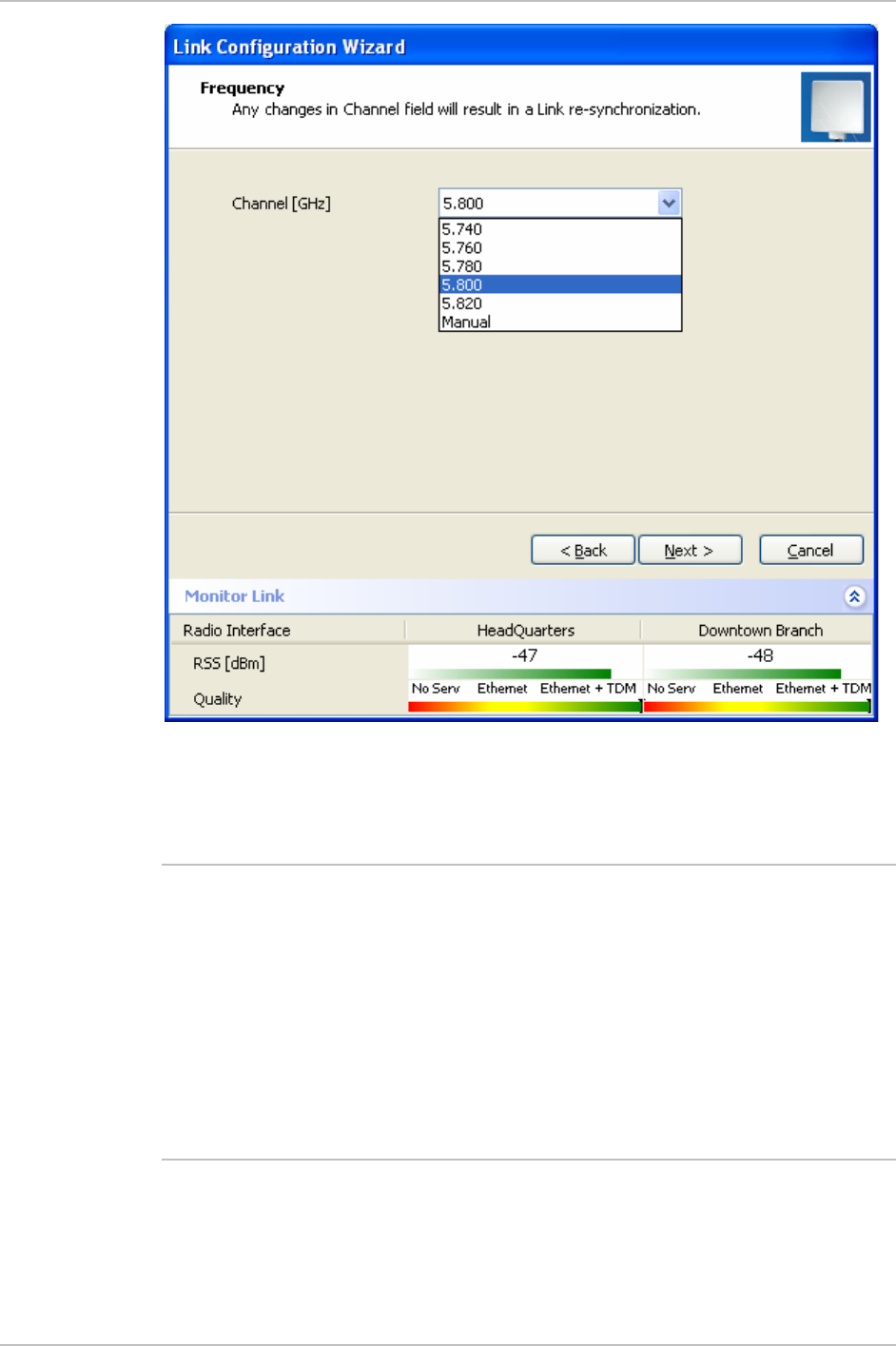
WinLink 1000 Installation and Operation Manual Chapter 3 Configuration
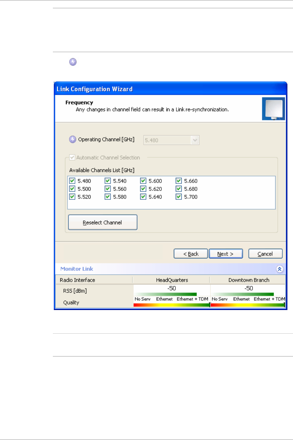
Figure 3-4. Link Configuration, Channel select dialog box
Selecting the Manual option provides the capability to configure the
channel in 5 MHz steps in the specified band of the product.
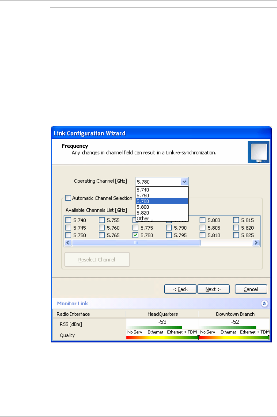
Some of the products support the Automatic channel selection. The
mode is activated in normal operation mode. During installation the
user must select the channel manually in order to optimize the antenna
alignment. Enabling automatic channel selection is perform be clicking
on the Automatic channel selection check box. After selecting this
mode, the available channel list is enabled, and the user can select
which channels are used for the automatic selection (at least two
channels must be selected). The reselect channel button is used to
change to a new channel from the available channels list.
Note
Performing Configuration of WinLink 1000 3-5
Chapter 3 Configuration WinLink 1000 Installation and Operation Manual
By reselecting channel, the radio starts scanning all the channels from
the available channels list and looks for radio activity in each of the
channels. It tries to select the optimal channels. If another channels is
desired the operating channel must be removed from the available
channel list.
Some product configurations support the DFS/TPC ETSI Standard. In
this standard, The Radio is detects Radars and selecting only channels
were no active Radars. According to the standard, a channel with active
Radar is prohibited for 30 minutes. Also before any transmission the
device probe the channel for Radar for a period of 60 seconds before it
can start transmission.
Figure 3-5. Link Configuration, Channel select dialog box with Automatic
Channel select
Note
3-6 Performing Configuration of WinLink 1000
WinLink 1000 Installation and Operation Manual Chapter 3 Configuration
This feature is for the 5.4GHz ETSI version product only.
DFS/TPC – Dynamic Frequency Select / Transmit Power control – ETSI
standard for the unlicensed band that eliminates interruption of the
wireless data equipment to the radar service.
The sign on the configuration Wizard and Status bar indicates that
the radar detection is on.
Figure 3-6. Link Configuration, Channel select dialog box with DFS
Automatic channel selection cannot be unchecked, due to ETSI
standard requirements.
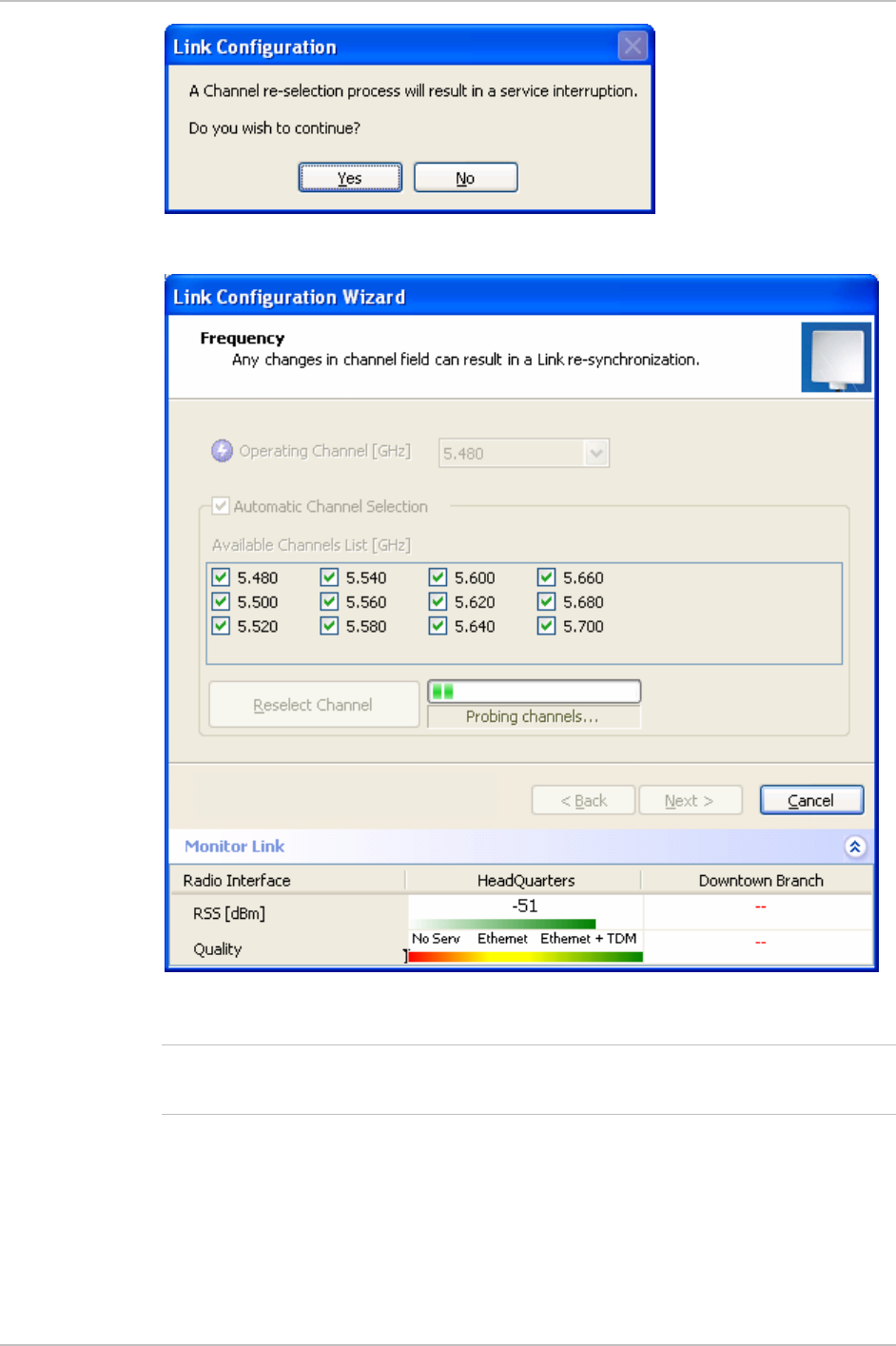
A Channel reselection process interrupts the service for the period of
scanning and re-synchronization of the link. In most of the product
this process takes few seconds. In products that support DFS/TPC this
process might take few minute (each channel must be monitored for a
60 seconds before any transmission can start.
Note
Note
Performing Configuration of WinLink 1000 3-7
Chapter 3 Configuration WinLink 1000 Installation and Operation Manual
Figure 3-7. Channel reselection confirmation dialog box
Figure 3-8. Reselection process
Reselection process can take up to few minutes. A bar with activity
displays the progress of the reselection process.
Note
3-8 Performing Configuration of WinLink 1000
WinLink 1000 Installation and Operation Manual Chapter 3 Configuration
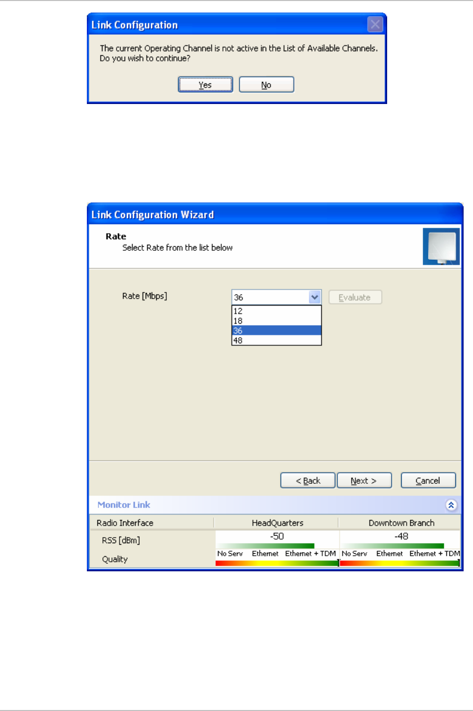
Figure 3-9. Reselection process "channel not active in list"
8. Click Next.
The Rate Select dialog box appears (see
Figure 3-10
)
Table 1-1 lists throughput rates and capacities.
Figure 3-10. Air Interface Rate select Dialog Box
9. Select a suitable air interface rate according to the services
required.
10. Click Evaluate.
Performing Configuration of WinLink 1000 3-9

Chapter 3 Configuration WinLink 1000 Installation and Operation Manual
The Evaluate button becomes enabled when a new rate has been
selected.
Note
11. A question box pops up, asking if you want to re-evaluate the link.
Click Yes to change the rate or No to keep the existing rate.
Selecting a new air-interface rate causes the system to change
its air-interface rate and commence evaluation of the link
performance at the new air-interface rate. This process of
evaluation takes a few seconds.
12. Click Next.
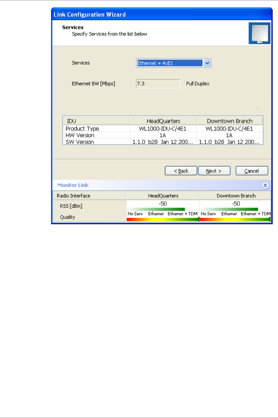
The Service Parameters dialog box appears.
Configuring Service Parameters
In the Service Parameters dialog box configure E1/T1 (x1 or x2) and
Ethernet parameters.
Î To configure E1/T1 and Ethernet:
1. In the Service dialog box, select one of the following:
E1/T1 – Select the E1/T1 field, if you intend to transmit E1/T1
data and Ethernet data.
The Ethernet BW field shows the remaining bandwidth in Mbps
available for Ethernet. The available bandwidth depends on the
number of E1/T1 ports selected.
Select the Ethernet field, if you intend to transmit Ethernet data
only
3-10 Performing Configuration of WinLink 1000
WinLink 1000 Installation and Operation Manual Chapter 3 Configuration
Figure 3-11. Service Parameters Dialog Box, E1/T1 Interface
Performing Configuration of WinLink 1000 3-11
Chapter 3 Configuration WinLink 1000 Installation and Operation Manual
Figure 3-12. Service Parameters Dialog Box, Ethernet only Interface
2. Click Next.
The Finish screen appears (see
Figure 3-13
).
The Finish screen shows a summary of the link configuration.
3-12 Performing Configuration of WinLink 1000
WinLink 1000 Installation and Operation Manual Chapter 3 Configuration
Figure 3-13. Configuration Link, Finish screen
3. Click Finish to complete the configuration wizard.
The Main screen is displayed.
Editing the Configuration Parameters
The configuration parameters can be edited for each site individually
without running a wizard.
Î To edit the Configuration Parameters:
1. Click configuration from the main menu.
2. Select which site to configure.
The configuration dialog box opens. (See
Figure 3-14
)
Performing Configuration of WinLink 1000 3-13
Chapter 3 Configuration WinLink 1000 Installation and Operation Manual
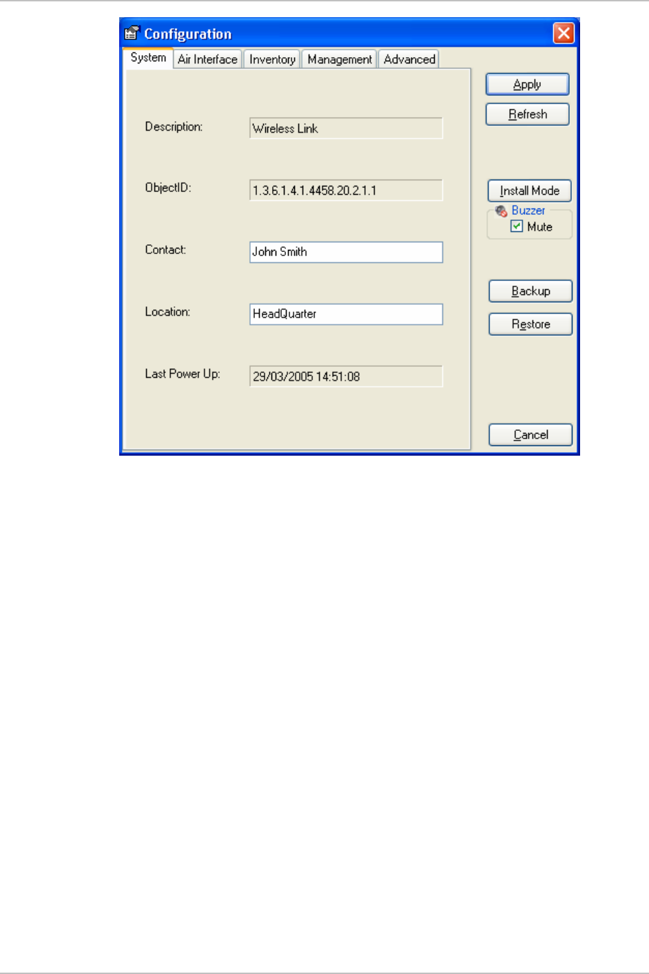
Figure 3-14. Configuration Dialog Box
3. In the Configuration dialog box, edit the data to for the link:
System Tab – The contact person and location details can be
edited.
Air Interface Tab – Used for changing the transmit power
Inventory Tab – This screen is read only and cannot be edited
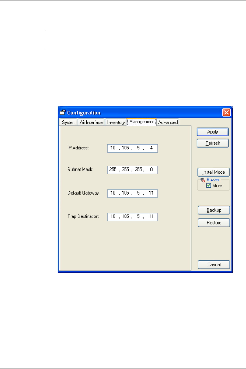
Management Tab – To configure the IP address, Subnet Mask,
Default Gateway, and the Trap Destination.
Backup button – Save a “backup” ini file with current
configuration.
Restore button – Load the “backup” ini created by the Backup
button.
Install Mode – return to Install Mode for the entire link. The
Buzzer can be muted by selecting the Mute check box before
click the Install Mode button.
4. Click Apply to save the changes.
3-14 Performing Configuration of WinLink 1000
WinLink 1000 Installation and Operation Manual Chapter 3 Configuration
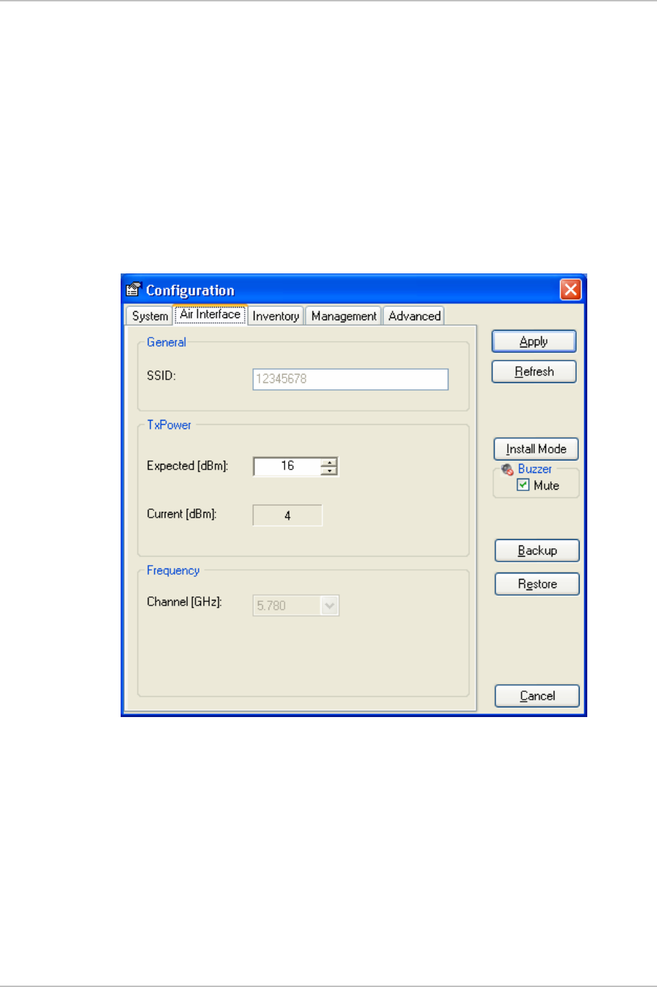
Changing the Transmit Power
Each ODU can be configured to have a different transmit power level.
Î To change the Transmit Power:
1. Click configuration from the main menu.
2. Select which site to configure.
The configuration dialog box opens.
3. Click the Air Interface Tab. (See
Figure 3-15
)
4. Select the required Transmit Power Level (See Figure 3-15, below).
Figure 3-15. Changing the Transmit Power
Defining the Management Addresses
Each site must be configured separately, first site A then site B.
Î To define the Management Addresses:
1. Click configuration from the main menu.
2. Select which site to configure.
The configuration dialog box opens.
Performing Configuration of WinLink 1000 3-15
Chapter 3 Configuration WinLink 1000 Installation and Operation Manual
3. Click the Management Tab (see
Figure 3-16
).
4. Enter the IP address of the ODU in the IP address field.
If performing configuration from the WinLink manager, the IP address
is entered in the login screen (Figure 2-3)
Note
5. Enter the Subnet Mask.
6. Enter the Default Gateway.
7. Enter the Trap Destination. This is the IP address of the PC running
the management application. The event log will be stored at this
address.
Figure 3-16. Configuration, Management
3-16 Performing Configuration of WinLink 1000
WinLink 1000 Installation and Operation Manual Chapter 3 Configuration
The Install mode button opens the Main Window for installation mode
for reinstalling the link.
The Backup and Restore buttons are for saving and restoring the
configuration files.
Notes
3.2 Bridge Configuration
Bridge configuration is required in various network topologies, such as
protection (1+1) and ring application.
Detailed description
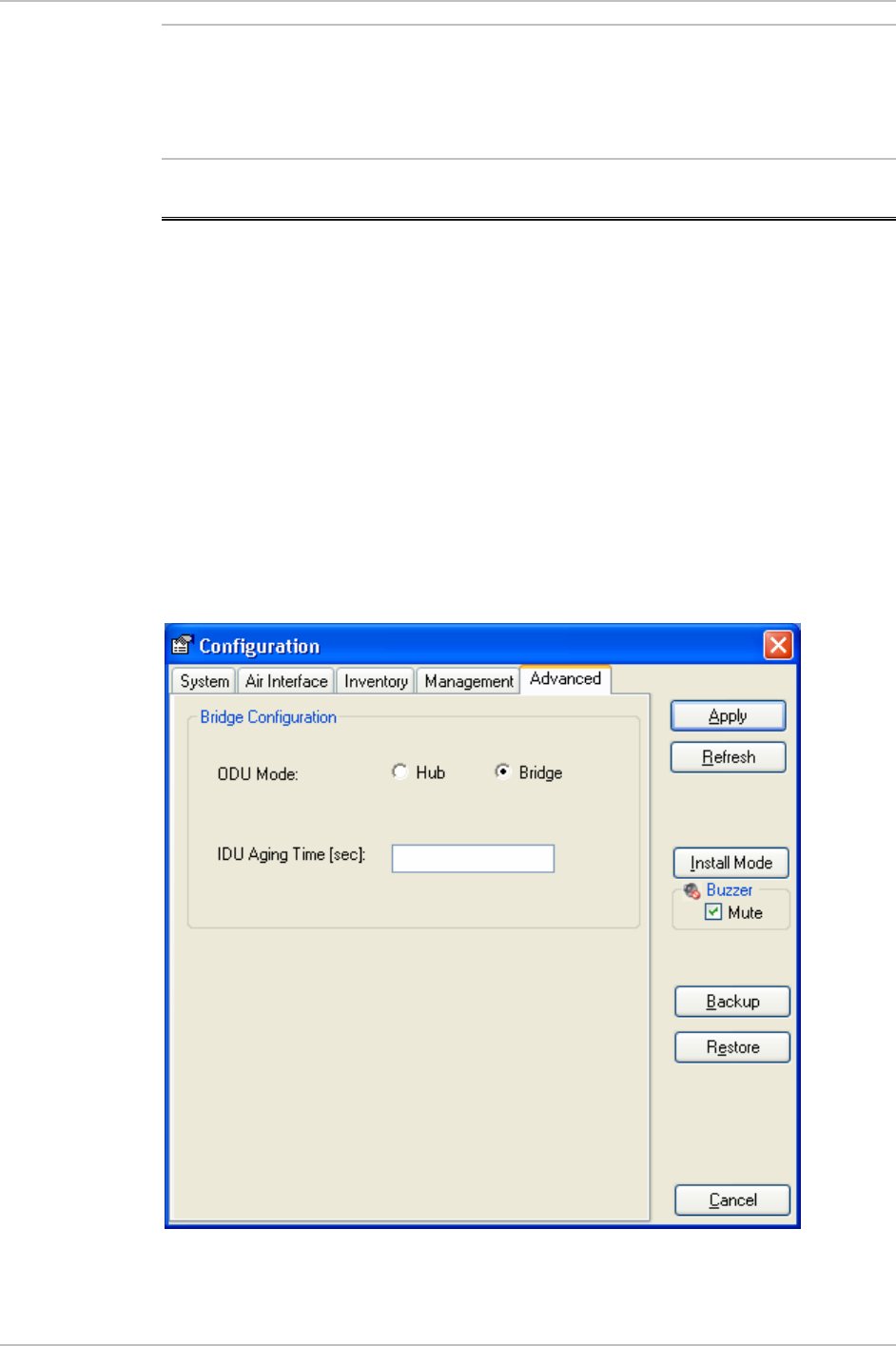
The bridge configuration parameters are available from the Advanced
tab of the site configuration dialog box (Figure 3-17 ). There are two
parameters:
• ODU bridge mode
• IDU Aging time
Figure 3-17. Site configuration dialog box
Bridge Configuration 3-17

Chapter 3 Configuration WinLink 1000 Installation and Operation Manual
ODU Bridge Mode
This parameter controls the ODU mode with two optional values,
• Bridge Mode (default) (Figure 3-17 ). In "bridge" mode the ODU
performs both learning and aging, the aging time of the ODU if
fixed.
• Hub Mode - in "hub" mode the ODU transparently forward the all
the packets over the wireless link.
Changing these parameters requires system reset.
Note
IDU Aging time
This parameter controls the IDU (E and C) aging time.
The IDU has 2K MAC address learning table. The aging time parameter
controls the time each MAC address is dropped from the table. Default
value is 300 (sec).
Change to these parameters is effective immediately.
Note
Each side of the link can be configured separately.
Note
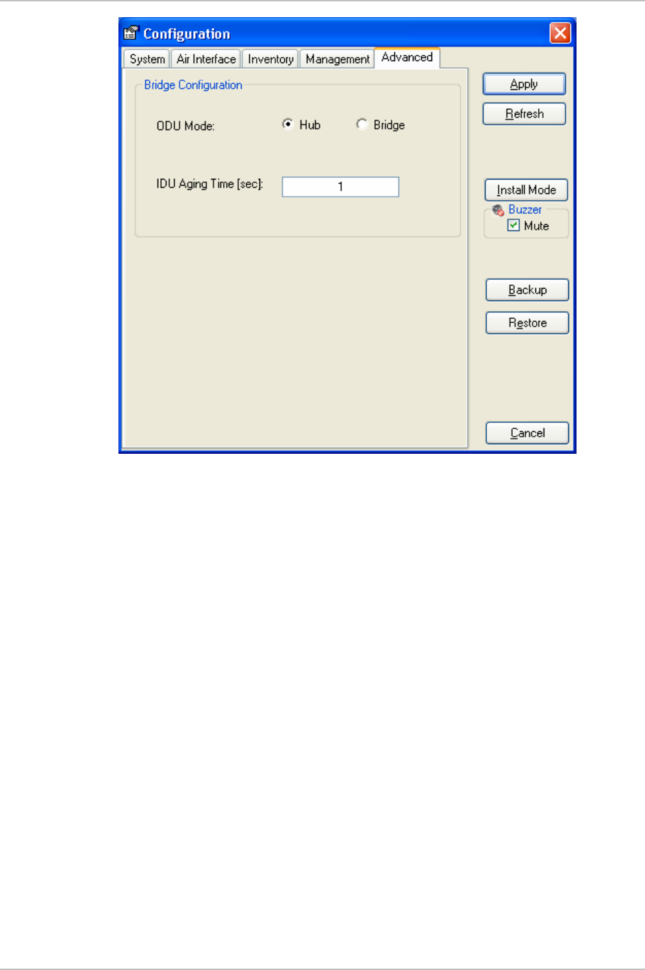
The following list detail common configurations, both sides are
configured with the same values.
• Standard (Default) Configuration for Ethernet Applications
IDU-E or IDU-C aging is set to 300 sec (ODU is set to Bridge mode,
Figure-1).
•
Fast aging mode
(for rapid network topology changes)
IDU-E or IDU-C aging is set to 1 seconds, ODU is set to Hub mode
(Figure 3-18).
3-18 Bridge Configuration
WinLink 1000 Installation and Operation Manual Chapter 3 Configuration
Figure 3-18. Hub mode selected
Bridge Configuration 3-19
Chapter 4
Operation
This chapter provides the following information for WinLink 1000:
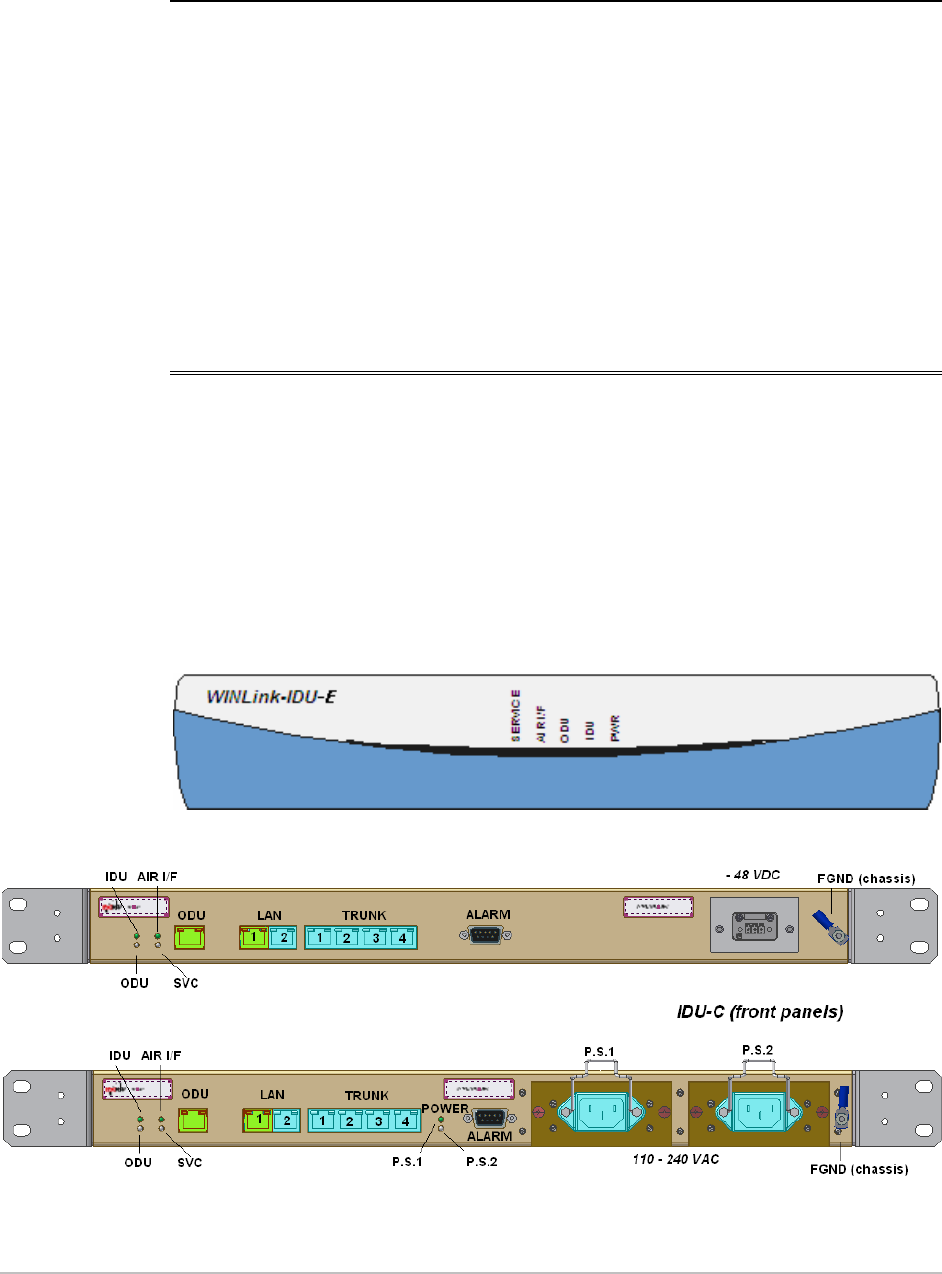
• WinLink 1000 front panel indicators on IDU-E and rear panel on
IDU-C.
• Operating procedures (turn-on, front panel on IDU-E and rear panel
on IDU-C indications, performance monitoring and turn-off)
4.1 Indicators
Panel Indicators
The panels of WinLink 1000 include a series of LED indicators that
show the operating status of the unit. Figure 4-1, below shows the
front panel of the WinLink 1000 unit, Table 4-1 describes the
indicators.
Figure 4-1. IDU Panels LEDs
Indicators 4-1

Chapter 4 Operation WinLink 1000 Installation and Operation Manual
Table 4-1. IDU Panel LEDs
Name Color Function
PWR Green ON – A power supply is ON IDU-E only
IDU Green
Orange
Red
ON– IDU operational
ON– During power-up only
ON – Failure
ODU Green
Red
ON – ODU-to-IDU communication link is operating
ON – ODU-to-IDU communication link is disrupted
AIR I/F Green
Orange
Red
ON – Wireless link is synchronized
ON – During installation only
ON – Wireless link lost synchronization
SERVICE Green
Orange
Red
ON – E1 or T1 line is synchronized
ON – Alarm detected at the remote interface
ON – Local or Remote loopback
ON – Alarm detected at the local interface
Connector LED Indicators
The IDU connectors of WinLink 1000 have LED indicators that show the
operating status.
Table 4-4
describes the indicators.
Table 4-2. WAN/LAN LEDs
Name Color Function Location
LINK Green ON – Good Ethernet link integrity WAN/LAN
connectors
ACT Yellow Blinks according to the Ethernet
traffic
WAN/LAN
connectors
Table 4-3. TDM Traffic Indicators
Function Green LED Red LED
OK On Off
AIS Off On
LOS Off On
Loopback On Blinking
4-2 Indicators

WinLink 1000 Installation and Operation Manual Chapter 4 Operation
4.2 Operating WinLink 1000
Turning On WinLink 1000
Î To turn on WinLink 1000:
• Connect the AC/DC converter to the IDU-E power connector and to
the mains; or -48VDC from rack or AC 110-240VAC.
The PWR indicator lights up and remains lit as long as the IDU is
receiving power.
WinLink 1000 requires no operator attention once installed, with the
exception of occasional monitoring of front panel indicators and
statistics data. Intervention is only required when WinLink 1000 must
be configured to its operational requirements, or diagnostic tests are
performed.
Operating WinLink 1000 4-3

Chapter 4 Operation WinLink 1000 Installation and Operation Manual
Normal Indications
Upon turning on WinLink 1000, the PWR LED in the IDU front panel
lights to indicate that WinLink 1000 is on.
Table 4-4
shows the correct
status of the indicators at power-up.
Table 4-4. WinLink 1000 Indicators at Startup
Indicator Color Status
PWR Green ON IDU-E only
IDU Orange
Green
ON for short duration during startup
ON during normal operation
ODU Green ON-shows normal operation
AIR I/F Orange
Green
ON for short duration during startup
ON shows normal operation
SERVICE Green ON shows normal operation
OFF when Service is configured for
Ethernet only
If the above LED indications do not appear following initial power turn-
on, refer to
Chapter 5
for the diagnostic test instructions.
Note
During normal operation, the PWR led stays ON; all other LEDs blink at
approximately a four second cycle.
Turning Off WinLink 1000
Î To turn off WinLink 1000:
• (IDU-E) Remove the AC/DC converter power cord from the mains.
(IDU-C) Remove 48VDC from rack or AC 110-240VAC (IDU-C).
Changing the Password
Î To change the password
1. From the Tools menu, select Change Password
2. The Change Password dialog box appears.
3. Enter current password, and new password.
4. Click Ok to confirm.
4-4 Operating WinLink 1000
WinLink 1000 Installation and Operation Manual Chapter 4 Operation
4.3 Managing WinLink 1000
Before starting a management session, make sure that a
communication link between local and remote units exists, the Link
Status indication bar in the middle of the Main menu must be green;
the
Radio Link - Sync
message appears in the event log (see Figure 4-
2).
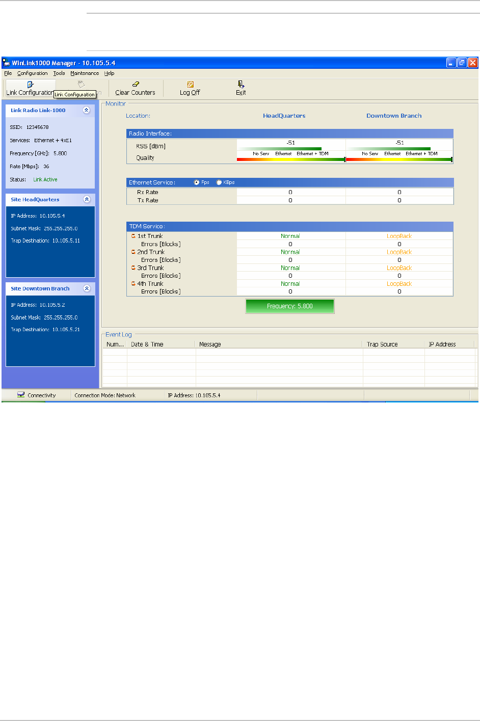
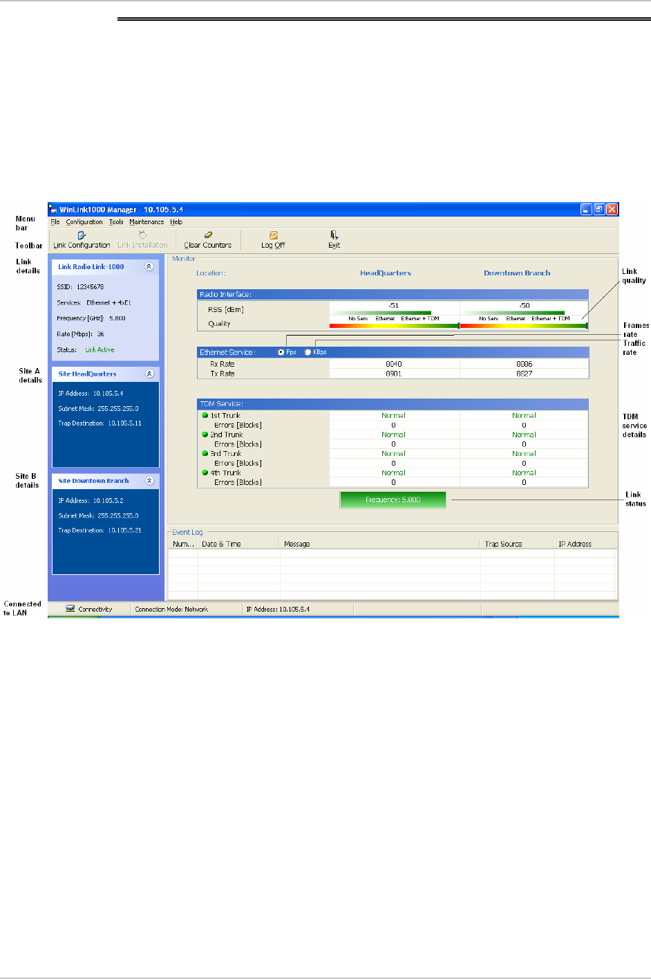
Figure 4-2. Main Menu, Wireless Link is Active
The WinLink Manager Main menu consists of the following elements:
• Toolbar – includes buttons serving for:
Changing configuration parameters of operating wireless link,
assigning text files for storing alarms, statistics and
configuration data (Link Configuration button)
Performing preliminary configuration of the system (Link
Installation button). This button is disabled once a link is
defined.
Clearing error counters (Clear Counters button)
Logging off WinLink Manager (Log Off button)
Managing WinLink 1000 4-5

Chapter 4 Operation WinLink 1000 Installation and Operation Manual
Exiting WinLink Manager (Exit button)
• Menu bar
File Menu – Log off, and exit
Configuration – use for link configuration, individual site
configuration or link installation
Tools – set preferences, event log handling, change password
Maintenance – Loopbacks, system reset.
• Link details pane – summarizes information on the radio frequency,
air interface rate, type of TDM service, and IP details of the local
and remote WinLink 1000 units.
• Monitor pane – displays the link quality between local and remote
devices and the following statistics:
Local/remote received traffic rate (in kbps)
Local/remote received frames rate (in fps)
Radio link status
E1 or T1 link status
Radio signal strength (RSS) in dBm
Block error rate
• Event log – stores both alarms and traps:
Alarms and traps also generated by NMS (e.g. counter clear,
device unreachable, etc.)
• Traps:
Monitoring for radar activity on channel <frequency> GHz. –
Apply to DFS/TPC products only. T trap is issued when the ODU
starts the looking for radar.
Radar activity was detected in <site>, on channel <frequency>
GHz. Apply to DFS/TPC products only. The ODU detected radar.
The channel is prohibit for 30 minutes.
Transmitting on channel <frequency> GHz. – The ODU started
transmission on a channel.
Channel scanning in progress. The ODU start searching the
remote ODU in all channels.
Configuration problem detected. Link installation required.
4-6 Managing WinLink 1000

WinLink 1000 Installation and Operation Manual Chapter 4 Operation
TDM Service - Alarm. (added in 1.1.3)
TDM Service - Normal. (added in 1.1.3)
Î To change link configuration parameters:
1. In the Main menu, click Configure Link.
The Configure Link wizard appears. See
Chapter 3
for
configuration details.
2. Click Next.
3. Continue through the configuration wizard and define the Link
name and ID, Channel, Rate and Services.
4. Once you finish changing configuration parameters, click Finish.
The system takes a few seconds to activate the link with the new
configuration.
Resetting WinLink 1000
Note
In order to maintain the communication link, always reset the remote
WinLink 1000 first
.
Î To reset WinLink 1000:
1. Click on maintenance, select the remote WinLink 1000 to reset.
2. Click on maintenance, select the local WinLink 1000 to reset.
Saving WinLink 1000 Configuration in a File
WinLink 1000 management software allows you to save configuration
parameters of the local and remote units on the management station
as an INI file. Each site is saved in a separate INI file.
Î To save configuration in a file:
1. From the Configuration menu, select the site to backup.
The Configuration dialog box opens (see
Figure 3-9
).
2. Click Backup.
3. In the Save As dialog box, indicate in which folder and under what
name configuration file is to be saved, and click Save.
Managing WinLink 1000 4-7

Chapter 4 Operation WinLink 1000 Installation and Operation Manual
Restoring a Configuration File
Configuration files (*.ini) can be uploaded from the management
station, if the WinLink 1000 database becomes corrupted. This can also
be used to distribute verified configuration files to all other units that
use the similar configuration.
Î To restore a configuration file to WinLink 1000:
1. From the Configuration menu, select the site to reconfigure.
The Configuration dialog box opens (see
Figure 3-9
).
2. Click Restore.
3. From the Open dialog, select *.ini file to upload and click OK.
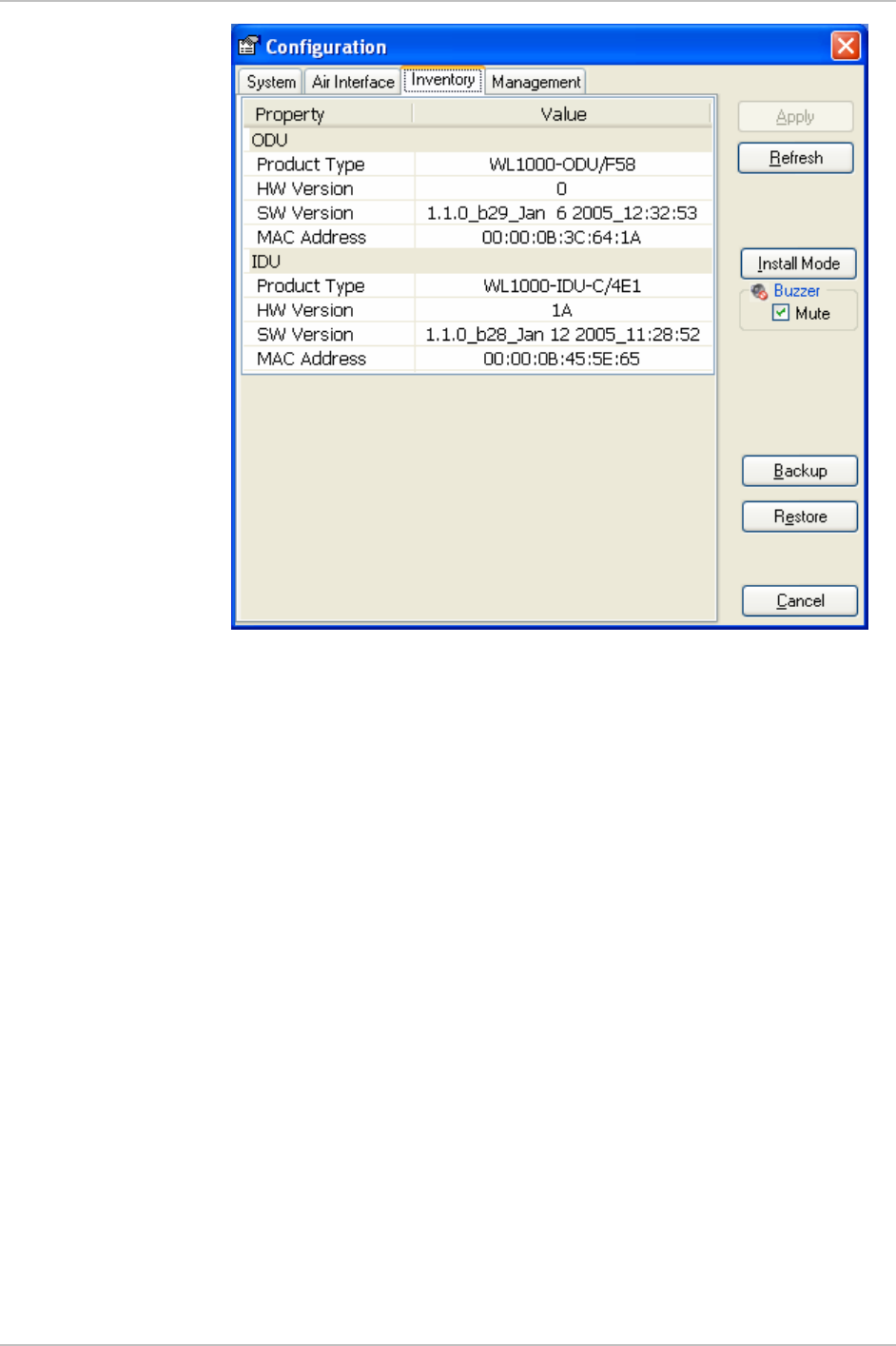
Displaying the WinLink 1000 Inventory
The WinLink 1000 inventory includes information on the hardware,
firmware and software versions of the local and remote units.
Î To display inventory:
• In the Configuration dialog box (see
Figure 3-9
), click the Inventory
tab.
The local and remote inventory information is displayed (see
Figure 4-3
).
4-8 Managing WinLink 1000
WinLink 1000 Installation and Operation Manual Chapter 4 Operation
Figure 4-3. WinLink 1000 Inventory
Managing WinLink 1000 4-9

Chapter 5
Diagnostics and
Troubleshooting
This chapter describes the WinLink 1000 diagnostic functions, which
include:
• Status indications, alarms, power-up self-test
• Statistics collection
• Diagnostic tests (local and remote loopbacks on E1 or T1 link).
5.1 Error Detection and Alarms
WinLink 1000 detects fault conditions of the radio and user links and
initiates alarms to alert the user.
Note
To store the event log, first define the IP address, subnet mask, default
gateway and trap address of the management PC, see
Chapter 3
for
details.
Alarms (traps) are displayed in the Event Log in the lower panel of the
Main Menu screen. The alarm log is saved as a TXT file.
The event log includes the following fields:
• Sequential number (ID)
• Date and time stamp
• Message
• Trap source
• IP address of the ODU that initiated alarm.
Error Detection and Alarms 5-1

Chapter 5 Diagnostics and Troubleshooting WinLink 1000 Installation and Operation Manual
Table 5-1. WinLink 1000 Alarms and Information Messages
Message Description
Radio Link – Sync Radio link is synchronized
Radio Link – Out Of Sync Radio link lost synchronization
Link Has Been Reset ODU was reset due to internal problem
TDM Interface – Normal TDM interface is operating properly
TDM Interface – LOS Loss of Synchronization is reported by TDM interface
TDM Interface – LOS Loss of Signal is reported by TDM interface
TDM Interface – AIS Alarm Indication Signal is reported by TDM interface
TDM Interface – Loopback A loopback is active on TDM interface
Link Resetting Wireless link reset from the management station. This
alarm is caused by automatic reset after link
configuration.
Local ODU Resetting The local ODU reset from the management station.
Monitor was stopped since no
connection to the link
No ODU-to-IDU traffic was detected during the last 20
minutes.
5.2 Collecting and Saving Statistics
WinLink 1000 constantly monitors traffic over the radio link and
collects the following statistics data:
• Site 1/Site 2 received traffic rate (in Kbps)
• Site 1/Site 2 received frames rate (in Fps)
• Radio signal strength (in dBm)
• Error (Blocks).
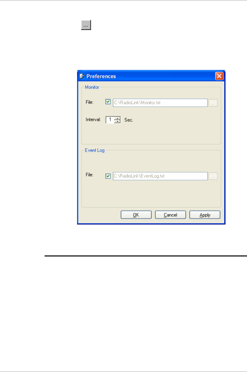
The statistics (monitor) log and event log can be saved as TXT files.
New alarms are automatically added to the text file, as they enter the
event log.
Î To save event log or monitor log:
1. From the Tools menu, choose Preferences.
The Preferences dialog box appears (see
Figure 5-1
).
2. From the Preferences dialog box, select the file to save.
5-2 Collecting and Saving Statistics
WinLink 1000 Installation and Operation Manual Chapter 5 Diagnostics and Troubleshooting
3. Click the check box to open the file for saving.
4. Click the button and in the Select File dialog box indicate in
which folder and under what name the alarm log file is to be saved,
and click OK.
5. Set the time interval for adding data to the file.
Figure 5-1. Preferences Dialog Box, Event Log Tab
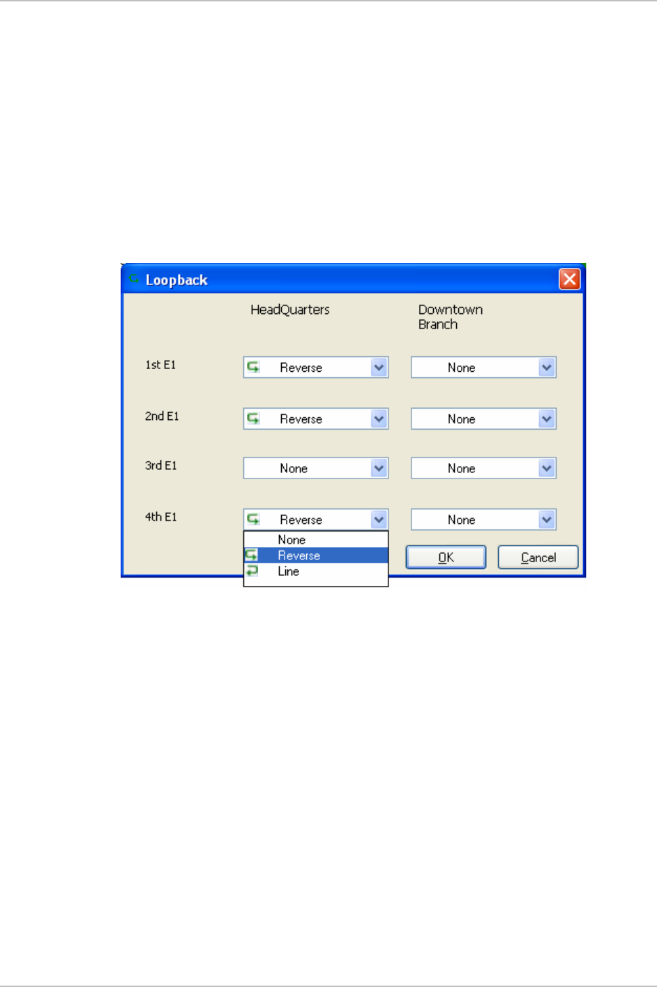
5.3 Running Diagnostic Loopbacks
WinLink 1000 supports activation of the internal and external
loopbacks on the local and remote units.
Î To activate a loopback:
1. From the Maintenance menu, choose Set Loopbacks.
The Loopbacks dialog box appears (see
Figure 5-2
).
2. From the Local or Remote drop-down box, select a loopback that
you intend to run, and click OK.
A confirmation message appears.
PM Running Diagnostic Loopbacks 5-3
Chapter 5 Diagnostics and Troubleshooting WinLink 1000 Installation and Operation Manual
3. Click OK to activate a loopback.
WinLink 1000 activates selected loopback. A loopback status
arrow in the Main menu turns green to indicate an active
loopback.
Î To deactivate a loopback:
• From the From the Local or Remote drop-down box of the
Loopbacks dialog box, select None and click OK.
A loopback is deactivated and the corresponding status arrow in
the Main menu becomes dimmed.
Figure 5-2. Loopbacks Dialog Box
Local External Loopback
Local WinLink 1000 can be set to an external loopback to test the local
E1/T1 port and its connection to the local side user equipment. In this
mode, data coming from the local user equipment is looped back to it
(see
Figure 5-3
). This loopback is initiated from a management station
connected to the local unit.
5-4 Running Diagnostic Loopbacks
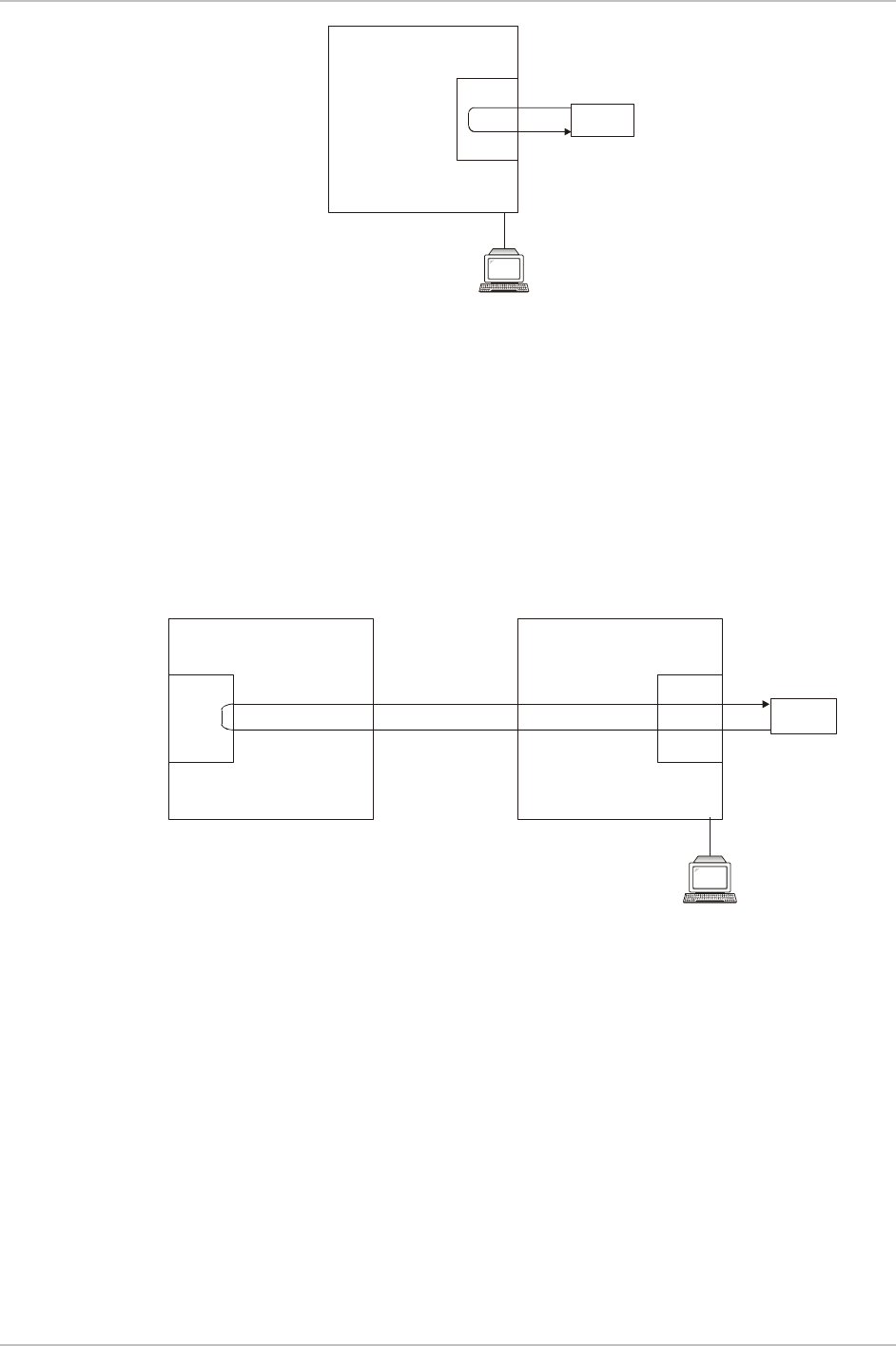
WinLink 1000 Installation and Operation Manual Chapter 5 Diagnostics and Troubleshooting
Tes ting
Equipment
Management
Station
E1
Interface
/T1
Local ODU
Figure 5-3. Local External Loopback
Remote Internal Loopback
Remote WinLink 1000 can be set to an internal loopback to test
connection between the local and remote units, the local E1/T1 port
and its connection to the local side user equipment. In this mode, data
coming from the local WinLink 1000 is looped back to it (see
Figure 5-
4
). This loopback is initiated from a management station connected to
the local unit.
Management
Station
E1/T1
Interface E1
Interface
/T1
Tes ti ng
Equipment
Remote ODU Local ODU
Figure 5-4. Remote Internal Loopback
Remote External Loopback
Remote WinLink 1000 can be set to an external loopback to test the
remote E1/T1 port and its connection to the remote side user
equipment. In this mode, data coming from the remote user equipment
is looped back to it (see
Figure 5-5
). This loopback is initiated by an
inband command sent from a management station connected to the
local unit.
PM Running Diagnostic Loopbacks 5-5
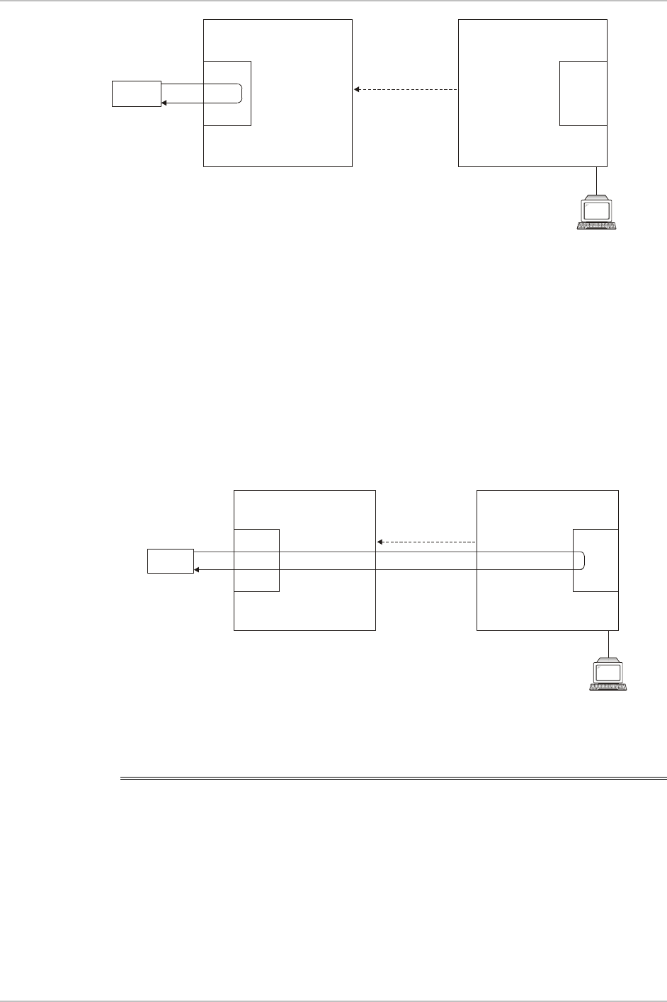
Chapter 5 Diagnostics and Troubleshooting WinLink 1000 Installation and Operation Manual
Tes ti ng
Equipment
Management
Station
E1
Interface
/T1 E1
Interface
/T1
Local ODU
Inband Loopback
Activation Command
Remote ODU
Figure 5-5. Remote External Loopback
Local Internal Loopback
Local WinLink 1000 can be set to close an internal loopback to test
connection between the local and remote units, remote E1/T1 port and
its connection to the remote side user equipment. In this mode, data
coming from the remote user equipment is looped back to it (see
Figure 5-6
). This loopback is initiated by an inband command sent
from a management station connected to the local unit.
Testi ng
Equipment
Management
Station
Local ODU
Inband Loopback
Activation Command
Remote ODU
E1/T1
Interface E1
Interface
/T1
Figure 5-6. Local Internal Loopback
5.4 Troubleshooting
The WinLink 1000 LEDs show faults in the system or the link. Use
Table 5-2 to diagnose the fault.
5-6 Troubleshooting

WinLink 1000 Installation and Operation Manual Chapter 5 Diagnostics and Troubleshooting
Table 5-2. Troubleshooting with WinLink 1000 LEDs
Led Status Remedy
PWR Off Check that AC adapter is connected to the IDU
and the AC power outlet.
IDU Orange Check that the IDU/ODU cable is properly wired
and connected.
ODU Red Check that the IDU/ODU cable is properly wired
and connected.
Orange Complete the installation procedure from the
management software.
AIR I/F
Red Check the ODU Antenna alignment. Check that
the radio configuration of both site A and site B
units are the same (channel and SSID).
Off Check the TDM service configuration in the NMS.
Orange Check that the system is not in loopback mode.
Check the site B IDU ports and cables and site B
external equipment.
SERVICE
Red Check the site A IDU ports, cables and external
equipment.
PM Troubleshooting 5-7

Chapter 5 Diagnostics and Troubleshooting WinLink 1000 Installation and Operation Manual
5.5 Frequently Asked Questions
Air Interface
Q: What performance issues will arise due to environmental
conditions?
A: The WinLink 1000 is not sensitive to environmental conditions.
However if heavy rain or snowfall is expected we can ensure the
performance by allowing a higher fade margin in the budget link
planning calculations.
Q: When using the WinLink 1000, what is the potential for interference
between our system and other cellular or wireless Networks devices?
A: The WinLink 1000 is a robust system. However, since it operates in
unlicensed band, there maybe some interference. Nevertheless, the
fact that we can manually set the frequency gives us the flexibility to
find a clear channel. In addition each WinLink 1000 link uses unique
user configurable SSID code.
Q: What protocol does the WinLink 1000 use, i.e. 802.11?
A: WinLink 1000 uses a proprietary protocol; this protocol contains
improved options that more efficiently support the clock
reconstruction from the TDM services.
Q: What type of security is offered on the WinLink 1000?
A: The WinLink 1000 has two levels of security:
Each unit uses a unique SSID - link specific code (up to 24
alphanumeric characters)
Proprietary protocol protects from eavesdropping from other
systems.
Q: Can we use horizontal and vertical polarization on the same
frequency to double the number of wireless links?
A: Installing two WinLink 1000 systems in the same band with cross
polarization provides 20–25 dB separations. Nevertheless, since there
are reflections, the cross polarization separation is decreased and
spatial separation is recommended.
5-8 Frequently Asked Questions

WinLink 1000 Installation and Operation Manual Chapter 5 Diagnostics and Troubleshooting
Q: In BAND C, can you add the frequency of 5.735 to the manual
selection in order to increase the number of 20 MHz channels to six?
A: Currently the system provides 5 fixed channels. Yet, the manual
frequency setting provides more flexibility of spectrum selection,
including 5.735 MHz.
Q: Can I use the WinLink 1000 with any vendor external antenna?
A: Yes. RADWin supplies the WinLink 1000 external ODU with an N-
type typical connector. Any vendor external antenna that can be
cascaded to our external unit can be use without problem. Please note
that dB losses in the cascading cable between the external ODU and
antenna should be taken into consideration. (In the supplied cascading
cable of one meter we have 1 dB loss)
Q: Do we need to add external arrestors on WinLink 1000 cables?
A: The WinLink ODU includes arrestors and lightning protection.
Therefore there is no need to add additional arrestors.
Q: What is the sensitivity for each rate of the WinLink 1000?
A: The sensitivities are:
Rate 12 Mbps -84 dB
Rate 18 Mbps -81 dB
Rate 36 Mbps -74 dB
Rate 48 Mbps -68 dB
Q: Does WinLink 1000 use DSSS technique?
A: No, WinLink 1000 uses the advanced OFDM technique.
Management
Q: Can we mange WinLink 1000 using SNMP other then the supplied
management software that comes with the units?
A: Yes. The WinLink 1000 is SNMP based, when using other SNMP
software, and after implementing RADWin MIB’s, the WinLink 1000 can
be managed.
Q: Can WinLink 1000 be managed and configured via Telnet?
A: No. Use only the WinLink software manager.
PM Frequently Asked Questions 5-9

Chapter 5 Diagnostics and Troubleshooting WinLink 1000 Installation and Operation Manual
Q: After reselection Channel Reselection link is not established for long
time. How can I recover the link?
A: Click "cancel", then open the site configuration dialog and set the
unit to install mode. The remote side of the link shall enter install
mode on the installation channel.
Services
Q: What is the actual Ethernet data rate and maximum throughput?
A: The Max net throughput of the WinLink 1000 is Full Duplex 18
Mbps.
Note
The WinLink 1000 is a symmetrical system
Q: Does WinLink 1000 withhold any MAC Addresses?
A: The WinLink 1000 is a layer 2 Bridge (VLAN transparent). The built in
switch contains a MAC Address table up to 2047.
Q: What are the BER values expected in the WinLink 1000 link?
A: 1E-10 (according to BER sensitivity threshold)
Antennas and Cables
Q: Can I use any category 5e cable in order to connect the IDU and
ODU?
A: The cable should be suitable for outdoor use, and shielded
Category 5e.
Competitve
5-10 Frequently Asked Questions

WinLink 1000 Installation and Operation Manual Chapter 5 Diagnostics and Troubleshooting
Q: What are the main advantages of the WinLink 1000 solution (e.g.,
wireline, wireless, etc.) over other possible alternatives?
A:
Easy and intuitive installation using audio indication
Easy configuration using the management software of overall
link site to site – there is no need to travel between the two sites
in order to change the configuration
Easy migration between transition channels – site to site
Full backup option – backup and restore using ini files
Very light ODU (1.5 kg)
No RF loses between IDU and ODU
Robust Air Interface Layer 2 ARQ insures “error-free” Ethernet
service even in harsh conditions. Retransmit mechanism for TDM
insures low BER
Integrated up to 4 E1/T1 and Ethernet radio over one single
product.
Supports a variety of applications Voice and Data over single
radio – no need for external mediation device.
Smooth migration to VoIP applications
Carrier class compliant with ITU standards for E1 andT1
Low and constant TDM latency (8 msec)
Extremely accurate recovered clock low cost replacement to PDH
radios.
5.6 Technical Support
Technical Support for this product can be obtained from the local
distributor from whom it was purchased.
PM Technical Support 5-11
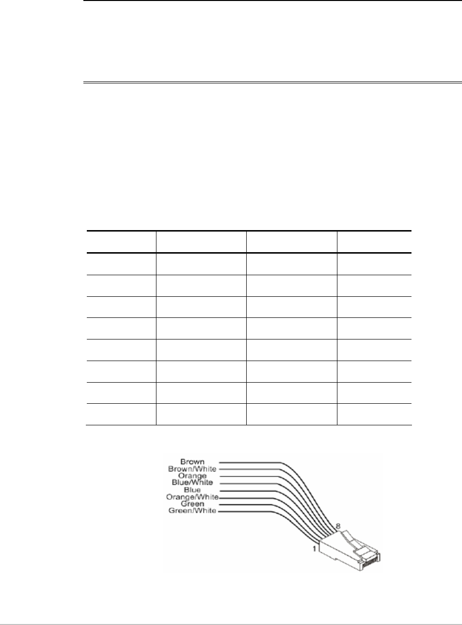
Appendix A
Wiring Specifications
A.1 ODU-IDU Cable
The ODU-IDU cable is standard CAT-5, 4 twisted-pair 24 AWG FTP.
The ODU-IDU cable is terminated in RJ-45 connectors on both ends. It
is covered by a cable gland on the ODU side for hermetic sealing.
Table A-1
shows the connector pinout.
Table A-1. ODU-IDU Cable Connector Pinout
IDU RJ-45 Wire Color Function ODU RJ-45
1 Green/White Ethernet (RxN) 1
2 Green Ethernet (RxT) 2
3 Orange/White Ethernet (TxT) 3
4 Blue Power (+) 4
5 Blue/White Power (+) 5
6 Orange Ethernet (TxN) 6
7 Brown/White
Power (−) 7
8 Brown
Power (−) 8
Figure A-1. RJ-45 wiring for IDU-ODU cable
ODU-IDU Cable A-1

Appendix A Wiring Specifications WinLink 1000 Installation and Operation Manual
A.2 User Port Connectors
The IDU includes ports for connecting E1/T1 and 10/100BaseT
Ethernet user devices.
Trunk Port
The Trunk (E1/T1) interface terminates in an 8-pin RJ-45 balanced
connector, wired in accordance to
Table A-2
.
Table A-2. E1/T1 Connector Pinout
Pin Function
4,5 Receive (input)
1,2 Transmit
(output)
LAN Port
The LAN 10/100BaseT interface terminates in an 8-pin RJ-45
connector, wired in accordance to
Table A-3
.
Table A-3. Fast Ethernet Connector Pinout
Pin Signal Function
1 TD (+) Transmit Data
(positive)
2 TD (–) Transmit Data
(negative)
3 RD (+) Receive Data
(positive)
6 RD (–) Receive Data
(negative)
A-2 IDU-C connectors

WinLink 1000 Installation and Operation Manual Appendix A Wiring Specifications
A.3 IDU-C connectors
Table A-4. Terminal Block 3-pin -48VDC
Pin Connection
Right ‘+’
Center Chassis
Left ‘-’
Table A-5. Alarm Connector (Dry-Contact)
Pin Description
1 Input #1 Positive
6 Input #1 Negative
2 Input #2 Positive
7 Input #2 Negative
3 Output #1 NC pin
8 Output #1 COM pin
4 Output #1 NO pin
9 Output #2 COM pin
5 Output #2 NO pin
IDU-C connectors A-3
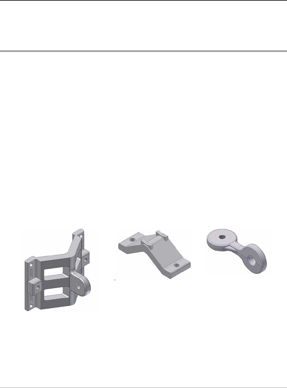
Appendix B
Mast and Wall Installation
B.1 Mounting the ODU
The ODU can be mounted on a mast or a wall.
ODU Mounting Kit Contents
The ODU mounting kit includes the following items:
• One Large Clamp (see figure B-1)
• One Small Clamp (see figure B-2)
• One Arm (see figure B-3)
• Four Screw hex head M8x40
• Two Screw hex head M8x70
• Four Washer flat M8
• Three Washer spring M8
• Two M8 Nuts
Figure B-1. Large
Clamp
Figure B-2. Small
Clamp
Figure B-3. Arm
Mounting the ODU B-1
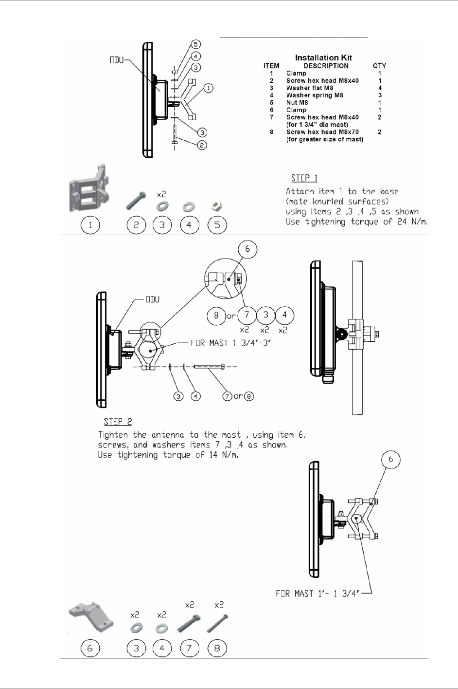
Appendix B Mast and Wall Installation WinLink 1000 Installation and Operation Manual
Mounting WinLink 1000 on a Mast
B-2 Mounting the ODU
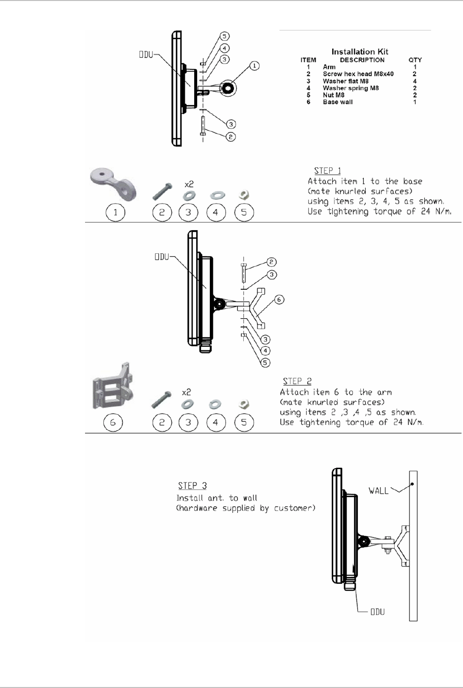
WinLink 1000 Installation and Operation Manual Appendix B Mast and Wall Installation
Mounting WinLink 1000 on a Wall
Mounting the ODU B-3

Appendix B Mast and Wall Installation WinLink 1000 Installation and Operation Manual
B.2 Mounting an External Antenna
The optional external antenna can be mounted on a mast.
External Antenna Mounting Kit Contents
The external antenna mounting kit includes the following items:
• Twelve flat washers
• Eight spring washers
• Eight hex nuts
• Four bolts
• One U-bracket
• One pivoting bracket
• Two metal strap clamps.
Î To install external antenna on the mast:
1. Attach the U-bracket to the back of the antenna using four flat
washers, four spring washers and four hex nuts.
2. Attach the pivoting bracket to the U-bracket using eight flat
washers, four spring washers, four hex nuts and four bolts.
3. Pass both strap clamps through the vertical slots in the pivoting
bracket.
4. Attach the antenna to the mast using the two strap clamps.
5. Adjust the required tilt using the angular scale and tighten all bolts
and nuts at the required position.
B-4 Mounting an External Antenna

Appendix C
Link Budget Calculator
C.1 Overview
The Link Budget Calculator is a utility for calculating the expected
performance of the WinLink wireless link and the possible
configurations for a specific link range.
The utility allows you to calculate the expected RSS of the link, and find
the type of services and their effective throughput as a function of the
link range and deployment conditions.
The Link Budget Calculator is supplied on the WinLink Manager CD.
After installation, it may also be accessed from the menu bar of the
WinLink Manager (see Figure C-1).
Overview
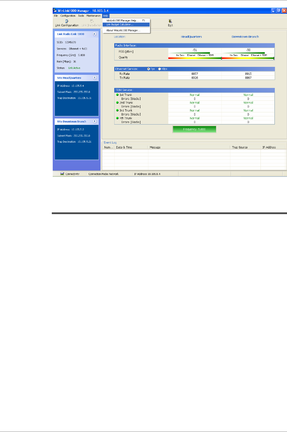
Link Budget Calculator WinLink 1000
Figure C-1. Accessing the Link Budget Manager Calculator
C.2 Using the Link Budget Calculator
The Link Budget Calculator comprises of one table where all the link
parameters are defined.
Using the Link Budget Calculator
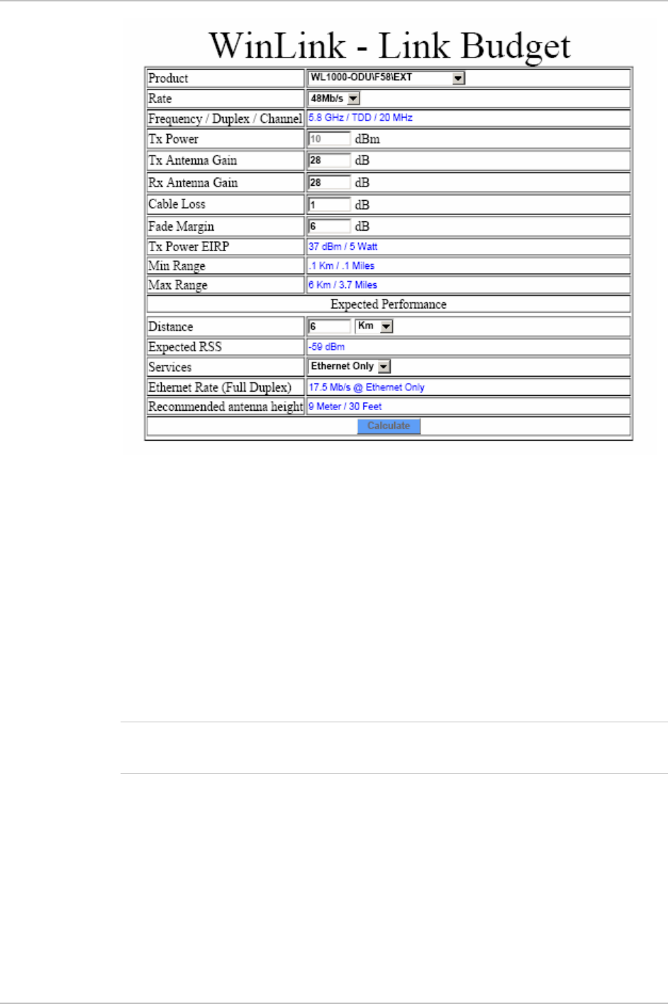
WinLink 1000 Link Budget Calculator
Figure C-2. Link Budget Screen
Î To calculate the link budget
1. Select your WinLink system product from the dropdown list of
products.
2. Select the rate from the dropdown list. The rate defines the air-
interface rate in Mbps. The system operates in TDD mode and has
overhead of the air-interface protocol and therefore the accurate
actual throughput is provided in the ‘Service’ Row and the effective
Ethernet throughput is provided in the ‘Ethernet Rate’.
Note
Throughput can be decreased as a function of range due to
propagation delay.
The remaining fields are completed automatically depending on the
product selected in the product field. Standard WinLink system
parameters are entered as default. Fields in blue boxes may be
edited if non-standard antennas and cables are used.
The Fade margin is the minimum margin that is required for LOS
conditions. For degraded link conditions, a larger fade margin
should be taken into account.
Using the Link Budget Calculator

Link Budget Calculator WinLink 1000
The Tx power EIRP for the system is given in dBm and Watts.
3. Select the required link distance and units of distance, kilometers
or miles.
4. Click Calculate
The Expected Performance parameters are calculated and
displayed in the lower part of the table.
Expected RSS – this is the number that the WinLink Manager
software shows when the WinLink ODUs are best aligned.
Services – Maximum E1/T1 services possible whilst
maintaining full duplex Ethernet throughput.
Ethernet Rate – Maximum throughput available with the
chosen system.
5. If the expected performance is not suitable for your application,
select a different data rate and re-calculate.
Using the Link Budget Calculator
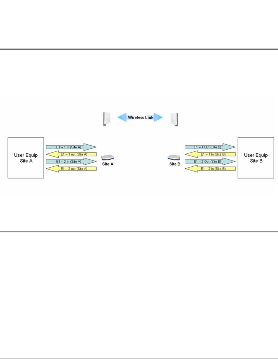
External clock requirements D-1
Appendix D
TDM Clock Configuration
D.1 Overview
This appendix describes the WINLink 1000 TDM clock configuration.
The following picture describes the E1 or T1 service configuration.
Figure D-1. E1 or T1 service configuration
D.2 External clock requirements
WINLink 1000 system assumes that all external equipments connected
to a single site use the same transmit clock. In the picture above, E1 –
1 in (site A) and E1 – 2 in (site A) must use the same clock. E1 – 1 in
(site B) and E1 – 2 in (site B) must also use the same clock, but this
clock can be a different clock that used in site A. The system
automatically selects a specific trunk for clocking according to the
rules described below.

TDM Clock Configuration WinLink 1000
D-2 Behavior in fault configuration
D.3 Clock selection
WINLink 1000 automatically selects a single trunk for the timing. The
trunk is selected according to the following rules:
• Smaller trunk number
• Both ends line state is in Normal
• Each line state change in the selected trunk re-triggers a new
clock selection according the above rules.
If the selected trunk is in Los of Signal state, the WINLink 1000 uses its
internal clock.
There are two methods to configure the user equipment.
• Master / Slave mode – One of the sites is defined as the clock
master while the other site is configured as a time loop (received
clock)
• Independent (Plesynchronous) Mode – Each site is configured as
timing Master
In both user configurations WINLink 1000 system re-generates the
selected
IN
clock of the opposite site and use it as the
OUT
clock for all
trunks.
In case that there is no
IN
clock in the selected trunk, WINLink 1000
use its internal clock (and re-generate it in the opposite site as an
OUT
clock).
It is user responsibility to verify that all IN clocks of a site are derived
from a single clock source.
D.4 Behavior in fault configuration
Where there are different transmit clocks at the external equipments of
the same site, pattern slips are expected. The pattern slip rate is
proportional to the clock difference. For example if in site A E1 – 1 in
clock is 2.048 Mb/s and E1 – 2 in clock is 2.048 Mb/s + 1 PPM and all
trunks are in normal state, a pattern slip of up to 2000 bits is expected
in trunk 2 every 1000 seconds.
Note

WinLink 1000 TDM Clock Configuration
Behavior in fault configuration D-3
Example 1
Site A clocks: E1-1 IN and E1-2 IN differ, and all trunks are in normal
condition, WINLink 1000 shall use trunk 1 for the timing and the
second trunk shall experience pattern slips (the rate of the pattern
slips is dependent on the ratio between the different clocks)
Example 2
Trunk 1 is disconnected and trunk 2 is in normal condition.
WINLink 1000 shall select trunk 2 for clock timing. Since trunk 1 is
disconnected it uses an internal clock as an input clock. The OUT clock
of both trunks is the re-generated clock IN 2, and therefore
WINLink 1000 shall display error blocks on clock 1 (represents the
clock difference between the internal clock and the IN 2 clock).

Index
—A—
Air Interface Rate, 3-9, 2-16
Alarms, 4-1, 4-2, 4-4, 5-1, 5-7
list of, 5-2
Aligning the ODUs, 2-9
Antenna, 2-3
automatic channel select, 3-5, 3-7, 2-13
—B—
Back panel, 4-1
Backup, 4-7
Buzzer.
See Buzzer sequence
Buzzer sequence, 2-10
—C—
Cable, ODU/IDU, 2-3
Calculator utility, 2-2
Change password, 4-4
Channel, selecting, 3-4, 2-12
Clearing counters, 4-5
clock
configuration, D-1
examples, D-3
external requirements, D-1
selection, D-2
transmit, D-2
clock configuration, D-1
clock master, D-2
clock selection, D-2
clocking, D-1
Configuration, 3-1
editing, 3-13
restoring, 4-8
saving, 4-7
Connecting the ODU to the IDU, 2-5
Connecting the Power, 2-6
Connectors
IDU-C, A-3
user port, A-2
Contents, of package, 2-2
—D—
Default gateway, 3-16
DFS, 3-4, 3-6, 3-7, 2-12, 2-14
Diagnostics, 5-1
Displaying inventory, 4-8
—E—
E1/T1 Connector Pinout, A-2
Event log, 4-6, 5-1, 5-2
External antenna, 2-3
mounting, B-4
external equipment, D-1, D-2
—F—
FAQ, 5-8
Fast Ethernet Connector Pinout, A-2
Fault configuration, D-2
Frames rate, 4-6
Frequency, 3-4, 2-13
Front panel, 4-1
—I—
IDU, 2-2
Connecting the ODU to the IDU, 2-5
Connector panels, 4-1
Front and Back panels, 4-1
IDU-C, 2-3, 2-18
IDU-E, 2-2, 2-18
ODU/IDU Cable, 2-3
IN clock, D-2
I-1

Index WinLink 1000 Installation and Operation Manual
Independent mode, D-2
Indications, 5-7
Indicators, 4-1, 4-2, 4-4
Information messages, 5-2
Installation, 2-1, 2-3, 2-4
of software, 2-7
performing, 2
prerequisites, 2
WinLink 1000 units, 1
Installation wizard, 2-10
Installing
of the Link, 2-10
internal clock, D-2
example, D-3
Inventory, 4-8
IP address, 3-16
ISM frequencies, 2-13
—L—
LAN Port, A-2
LEDs, 4-2, 4-4, 5-7
Link Budget Calculator, 2-2
overview, C-1
using, C-2
Link configuration, 3-2
Link details, 4-6
Link installation, 2-10
Log, 4-6, 5-1, 5-2
Loopback, 5-3
external, 5-4
internal, 5-5
Los of Signal, D-2
—M—
Main menu, 4-5
Maintenance, 4-7
Management, 4-5
Management addresses, 3-15
Management software, 2-7
Manual frequency, 2-13
Master mode, D-2
Monitor log, 5-2
Monitor pane, 4-6
Mounting
mast, B-2
ODU, 2-4
wall, B-3
—N—
Normal
line state, D-2
—O—
ODU, 2-1, 2-2
Aligning, 2-9
Connecting the ODU to the IDU, 2-5
mounting, 2-4
ODU/IDU Cable, 2-3
Transmit Power, 3-15
ODU-IDU cable
pinout, A-1
Operating channel, selecting, 3-4, 2-12
Operating temperature, 2-2
Operation, 4-1
OUT clock, D-2
example, D-3
Outdoor Unit (ODU)
aligning, 2-9
buzzer, 2-9
mounting, B-1
—P—
Package contents, 2-2
Password
changing, 4-4
default, 2-9
pattern slips, D-2
example, D-3
Pinout
E1/T1 Connector, A-2
Fast Ethernet Connector, A-2
Plesynchronous mode, D-2
Power, connecting, 4-3, 2-6
Power, of transmission, 3-15
Power, turning off, 4-4
PPM, D-2
Prerequisites, 2-2
—Q—
Quality bar, 2-13
Quick start, 1
I-2

WinLink 1000 Installation and Operation Manual Index
—R—
Radio link status, 4-6
Radio signal strength, 4-6
Rate, selecting, 3-9, 2-16
ratio
different clocks, D-3
Requirements, 2-2, 2-7
Reset, 4-7
Restoring configuration, 4-8
re-triggers, D-2
—S—
Saving the configuration, 4-7
Selecting the channel, 3-4, 2-12
Service parameters, 3-10
Setup, 2-1, 2-3
of software, 2-7
Site Requirements, 2-2
Slave mode, D-2
slips
pattern, D-2, D-3
Software, 2-7
SSID, 2-12
Statistics, 4-6, 5-2
Subnet mask, 3-16
Support, 5-11
System, 2-1
—T—
Technical support, 5-11
Temperature, operating, 2-2
timing, D-2
examples, D-3
Toolbar, 4-5
TPC, 3-6, 3-7, 2-14
Traffic rate, 4-6
transmit clock, D-1, D-2
Transmit Power, 3-15
Trap destination, 3-16
Troubleshooting, 5-1, 5-7
trunk number, D-2
Trunk Port, A-2
Turning off, 4-4
Turning on, 4-3
Typical installation, 2-4
—U—
User equipment
connecting, 3
User port
connectors, A-2
—W—
WinLink 1000 System, 2-1
WinLink 1000 units
installing, 1
normal indications, 4
operating, 4
troubleshooting, 5
I-3