Rain Bird Controls Division WRH900 Irrigation Control Remote Transmitter User Manual WirelessEagle RotorListen 1
Rain Bird Corporation - Controls Mfg. Division Irrigation Control Remote Transmitter WirelessEagle RotorListen 1
User Manual

WIRELESS EAGLE™500/700 SERIES ROTOR
WIRELESS ROTOR HANDHELD
WIRELESS ROTOR LISTENING DEVICE
OPERATIONS MANUAL
This device complies with part 15 of the FCC Rules. Operation
is subject to the following two conditions:
(1) This device may not cause harmful interference, and
(2) This device must accept any interference received, including
interference that may cause undesired operation.
The term “IC:” before the certification/registration number only
signifies that the Industry Canada Technical Specifications were met.
P/N/ 63592211/03
Rain Bird Corporation
Golf Division
6991 East Southpoint Rd, Building 1
Tucson, AZ 85706 USA
Phone: (626) 812-3400
Fax: (626) 812-3411
Technical Assistance
1-800-984-2255

Page 1
TABLE OF CONTENTS
Description Page
Introduction 2
Maintenance 3
Wireless Handheld 4
Configure Key Function 6
Control Key Functions 8
Unit Key Functions 11
Rain Bird Messenger 13
Listening Device 17
Station Detail Configuration 19
Page 2
INTRODUCTION
New Paging Feature Simplifies Expansion Needs
The Wireless Rotor from Rain Bird offers the following:
• Quick and easy to retrofit or make additions to your
course, even as an emergency replacement.
• Reduced risk of collateral lightning damage.
• No wire or satellite costs.
• Reduces turf damage.
• Easy conversion from a block system.
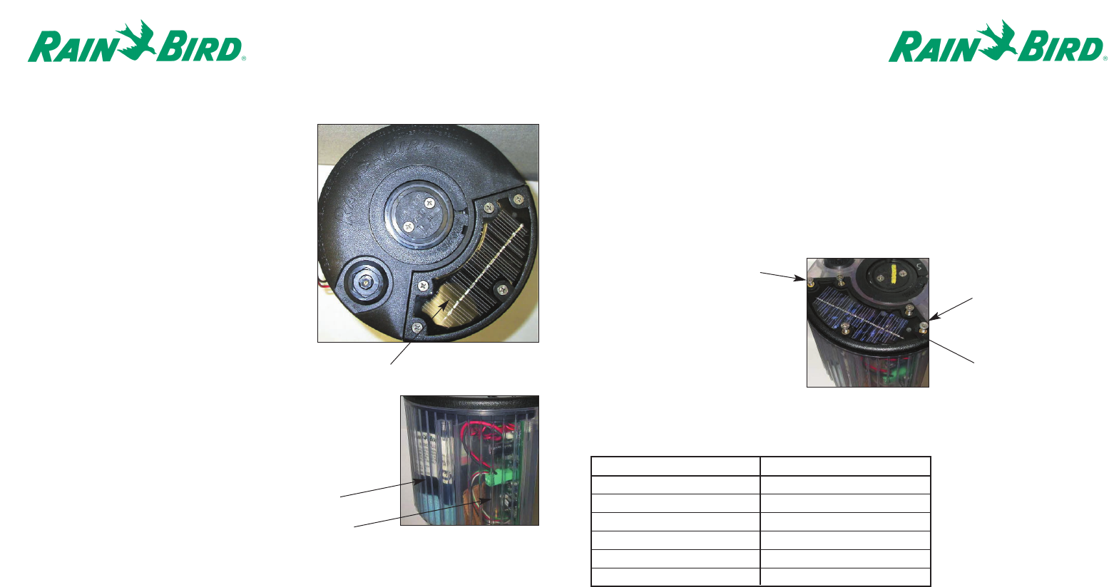
The Rain Bird Wireless Rotor
This unique rotor has an enclosed sealed-lead
rechargeable battery.
The battery level is maintained by the solar
panel at the top of the rotor case. The battery is
positioned in the enclosed compartment next
to the communication board.
Page 3
MAINTENANCE
The Wireless EAGLE 500/700 series Rotor is an exclusive Closed-Case design. All of the superior
characteristics of the EAGLE rotor are featured in this product, including the Rain Bird standard top-
serviceable features. For performance data and maintenance information, please refer to the EAGLE
Series Rotor catalog.
Special screws have been used to assist in the prevention of theft and to maintain the integrity of the
sealed battery/communication board. Please contact Rain Bird for assistance when the battery
needs servicing or any troubleshooting is required.
LED Diagnostics
The Rotor enters a diagnostics mode following a successful configuration or by receiving a specific
command from the Handheld Device.
LED Action State Description
Stays on Continuously Battery Level Too High
Continuously Flashing Battery Level Good
2 Flashes then 3 sec delay Battery Level Low
Always OFF System Shutdown
1 Flash then 3 sec delay Solar Panel Error
Continuously Flashing Solar Panel Good
Solar Panel
Anti-theft screw
Anti-theft screw
LED
Battery
Communication Board (Clear plastic case used for
illustration purposes only.)
Page 5
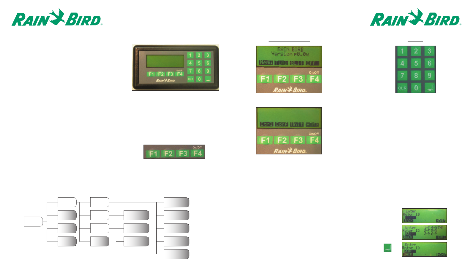
Home – Main Menu Keypad
Entering the Rotor ID
To configure and control the Wireless Rotors, a logical address must be assigned to the rotor in the
Handheld. This will be the same identification used in the Central Control Software.
The Rotor ID consists of the hole #, the area handle, and the station. Both the hole # and the station
entries are configured for two-digits. For example, hole #3 – rough - station 11 would be entered as
03311 as shown below:
Page 4
THE WIRELESS HANDHELD DEVICE
The Wireless Handheld Device provides
operating capability in the field, performing a
number of functions without having to send a
page through the central control computer. Prior
to being able to communicate with a Wireless
Rotor using the Central Control, the Rotor must be
configured With the Handheld Device.
The Handheld Device is powered by two AA Batteries. To preserve the life of the batteries, several
power management features have been implemented. If the Handheld Device remains idle for
longer than 10 minutes, the unit will be shut off automatically. Additionally, the backlight feature of
the LCD Display screen will only remain active for 10 minutes. After 10 minutes, the LCD Display
screen will return to its normal mode of operation.
To turn the Handheld Device on, momentarily press
the F4 Function key. (Handheld may take up to
30 seconds to show the main menu.)
To turn the Handheld Device off, momentarily press
the F4 Function key from the Main Menu.
Handheld Menu Structure
Following is a graphical representation of the Menu Structure for the Handheld Device:
Menu – Sub-Menu
Off Send Time
Home
1
2
2F4
F3
F2
F1 Enter
Rotor ID
Enter
Rotor ID
F4
F3
F2
F1
13
4
5
BLIT
Time
Menu
Enter Config
Data
Setup Time
Clear Rotor
Database
TableChg
RotorOps
PWR Ctrl
Diag
Unit
Conf
Ctrl
MAIN
MENU
F1 – Menu
F2 – Time (Shows current
time/date set in the
handheld)
F3 – BLIT (Backlight)
F4 – OFF
F1 – Ctrl (Control)
F2 – Conf (Configure)
F3 – Unit
F4 – Home (Returns to the main menu)
1. Enter “03”on the keypad for the hole #.
2. Once the hole number is entered, the numerical equivalent for each of
the area handles will be displayed. Select the corresponding number
on the keypad.
3. To complete, input the station number “11”and then press <enter>
on the keypad
Page 7
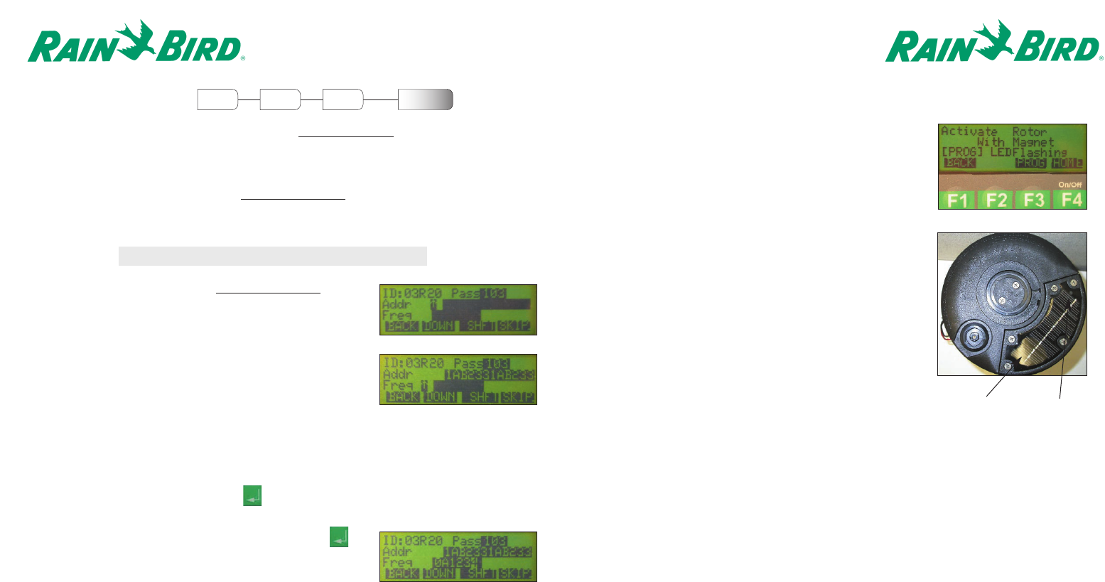
5. The Handheld is now ready to configure the Rotor.
Once the “Activate Rotor With Magnet”screen
appears, activate the rotor by passing a magnet
across the LED display area of the
Solar Panel. The magnet should pass over the LED
once with the surface of the magnet slightly
brushing along the top of the solar panel.
Observe the flashing of the LED on the Solar Panel.
Once the LED begins to flash approximately once
every second, press the Prog <F3> key on the
Handheld.
After approximately 30 seconds, the solenoid should
click twice to indicate that the Rotor has been
successfully configured.
6. By default, the handheld will prompt for the next
Rotor ID to be configured. To enter another Rotor ID,
return to step 1 of this section. If finished, press the
Home <F4> to return to the main menu.
Page 6
CONFIGURING A ROTOR
Prior to being able to perform any of the functions for Controlling a Rotor,the Rotor configuration
data must be input into the Handheld and then transferred into the Rotor with the use of a magnet.
The configuration data for the Wireless Rotor requires that the Capcode and Frequency be converted
into hexadecimal code. Rain Bird will supply the converted codes. In addition to assigning a logical
address to each Rotor as discussed in the Entering the Rotor ID section, a unique PassCode must
also be assigned. This three-digit numerical code allows each rotor to determine whether or not a
particular command from the Central Control Software or Handheld pertains to itself.
F1 F2 Enter
Rotor ID
Enter Config
Data
MAIN
MENU
Menu Conf
1. Enter the Rotor ID as shown in the Entering the Rotor ID section.
2. At the Configuration Data Screen, begin by entering the
PassCode using the keypad. After entering the third digit, the
cursor will automatically move to the Address line.
3. Enter the Address information provided by Rain Bird. After
the last character has been entered, the cursor will automatically
move to the Frequency line.
4. Enter the Frequency information provided by Rain Bird.
After the last character has been entered, press <enter>
on the keypad. Remember to use the Shft <F3>
followed by the number 1-6 to enter A-F.
Note: It is best to configure the rotor prior to installation
Some addresses and frequencies contain the characters A-F. To enter one of these characters,
press the Shft <F3> followed by the number 1-6, where 1 represents A and 6 represents F.
If other Rotors have been previously programmed into the Handheld, you can scroll through each
address by continuously pressing the Down <F2> key until the correct address is found. Once the
correct address is found, press <enter> on the keypad.
Solar Panel LED
Page 9
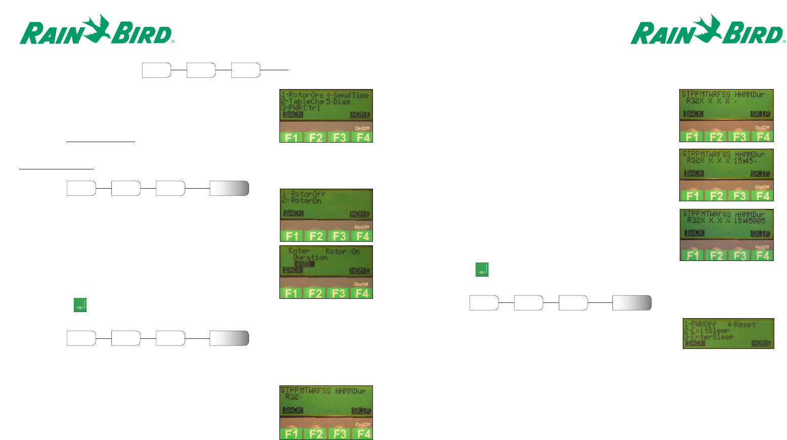
After the schedule type has been entered, select the days(s) for
irrigation to occur. Press any numeric key on the keypad when
the cursor is below a particular day to have that day included in
the irrigation schedule. Press Skip <F4> to prevent a particular
day from being included in the irrigation schedule.
After the day(s) have been selected, enter the start time (HH:MM)
for the irrigation to begin in military time.
For example, 3:45 PM would be entered <1545>.
After the start time has been been selected, enter the duration.
The duration is a three-digit value representing the number of
minutes to irrigate (240 minute maximum).
For example, <005> represents 5 minutes.
Press <enter> on the keypad to send the schedule
to the rotor.
Page 8
CONTROLLING A ROTOR
The Handheld provides the ability to manually turn on/off
irrigation, program a default schedule, control power modes,
synchronize the clock, and initiate diagnostic modes with a
configured Rotor. If a Rotor has not been previously configured,
return to the Configuring a Rotor section.
In order to control a rotor, enter the Rotor ID as shown in the
Entering the Rotor ID section.
RotorOps
Within the RotorOps menu, the Rotor can be manually turned on
or off.
To turn the Rotor Off, press <1> on the keypad.
To turn the Rotor On, press <2> on the keypad and enter a
duration. The duration is a three-digit value representing the
number of minutes to irrigate (240 minute maximum).
For example, <005> represents 5 minutes.
Press <enter> on the keypad to send the schedule
to the rotor.
Select <1> for a one-time event or <2> for a reoccurring event
on the keypad for a schedule type. If <1> is selected, then the
default program will only occur one time. The reoccurring
selection <2> allows a day of week schedule to be entered.
F1 F1 Enter
Rotor ID
MAIN
MENU
Menu Ctrl
1
F1 F1 Enter
Rotor ID
RotorOps
MAIN
MENU
Menu Ctrl
2
F1 F1 Enter
Rotor ID
TableChg
MAIN
MENU
Menu Ctrl
TableChg
Within the TableChg menu, the Rotor can be programmed with a default program, which would
become active if communication with the Central Control Software is lost.
PWR Ctrl
Within the PWR Ctrl menu, the Rotor can be commanded to change
between various power management modes and to reinitialize itself.
By selecting <1> PWROff, the Rotor will completely shut its internal power off. The unit will not be
capable of communicating to either the Central Control Software or the Handheld in this mode.
Additionally, the Rotor will not be capable of running any of the irrigation schedules programmed
into it. For the Rotor to acknowledge this command from the Handheld, the user must provide the
appropriate three-digit Security Password. A magnet will be required to reactivate the Rotor for
operation.
3
F1 F1 Enter
Rotor ID
PWR Ctrl
MAIN
MENU
Menu Ctrl
Page 11
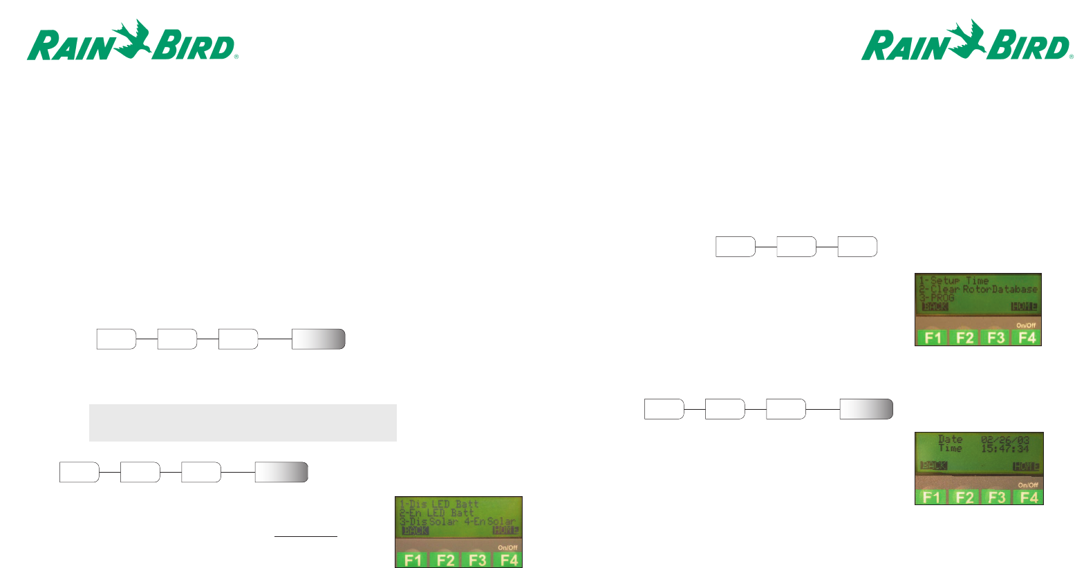
HANDHELD UTILITIES
To maintain consistency with the Central Control Software and
the Wireless Rotors, the Handheld has been designed with
several functions that have direct impact on the data and the
ways that it is stored.
At this time, the Synchron feature is not available. This feature
will allow the Handheld and Central Control Software
Databases to be synchronized.
Setup Time
Within the Setup Time menu, the clock for the Handheld can be
changed. The initial location of the cursor will be the first digit
of the month. Enter the Date using a MM/DD/YY format.
For example, February 26, 2003 would be
entered as 02/26/03.
Once the Date has been entered, enter the new time
(HH:MM:SS) in military format.
For example, 3:47pm 34 seconds would be
entered as 15:47:34.
Note: Each field of the Date/Time requires two digits.
Page 10
By selecting <2> ExitSleep, the Rotor will exit its Hibernation state and return to its normal mode
of operation. This command will only be accepted by the Rotor if selected between 10:30 AM and
1:30 PM.
By selecting <3> EnterSleep, the Rotor will enter its Hibernation state. While the Rotor is in this
state, it will not be capable of running any of the irrigation schedules programmed into it. While
in this state, the Rotor will activate itself to listen for the ExitSleep command only between
10:30AM and 1:30PM. For the Rotor to acknowledge this command from the Handheld, the user
must provide the appropriate three-digit Security Password. Alternatively, a magnet can be used
to reactivate the Rotor for operation without the use of the Handheld.
By selecting <4> Reset, the Rotor will begin a sequence to reinitialize itself. This command
should only be used in the case that the Rotor fails to respond to commands issued from the
central control software of handheld.
Send Time
By selecting Send Time, a command will be sent to synchronize the time within the rotor with the
time within the handheld.
Note: Make sure the Handheld is set for the correct date
and time prior to selecting Send Time.
Diag
Within the Diag Menu, the rotor can be commanded to enable and disable
the display of the diagnostics using the rotor LED for the state of the
battery and solar panel. Reference the table in the Maintenance section to
differentiate between the various states of the battery and solar panel.
By selecting <1> Dis LED Batt, the rotor will disable the displaying of
diagnostics on the LED for the state of the battery.
4
F1 F1 Enter
Rotor ID
Send Time
MAIN
MENU
Menu Ctrl
5
F1 F1 Enter
Rotor ID
Diag
MAIN
MENU
Menu Ctrl
F1 F3
MAIN
MENU
Menu Unit
1
F1 F3 Setup Time
MAIN
MENU
Menu Unit
By selecting <2> En LED Batt, the rotor will enable the displaying of diagnostics on the LED for the
state of the battery for five (5) minutes.
By selecting <3> Dis Solar, the rotor will disable the displaying of diagnostics of the LED for the
state of the solar panel.
By selecting <4> En Solar, the rotor will enable the displaying of diagnostics of the LED for the state
of the solar panel for five (5) minutes.
Page 13
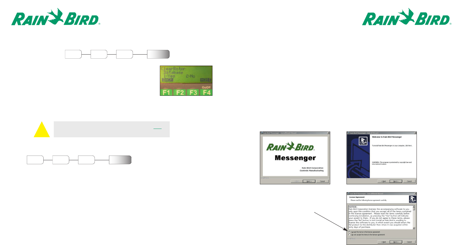
RAIN BIRD MESSENGER SET-UP
Install the software CD labeled Rain Bird Messenger. Please cancel all programs that are
currently running. Confirm that Weather Watch is also closed if you are communicating with a
Weather Station via a phone connection.
1. Double Click on the My Computer icon.
2. Double Click on the CD drive (usually the d or e drive).
3. Double Click on the yellow folder labeled Messenger.
4. Double Click on the yellow Setup folder and then on Setup.exe.
5. The following three screen shots will open. Please click the Next button on each screen.
Page 12
Clear Rotor Database
Within the Clear Rotor Database menu, the user must verify whether
or not to clear the entire database on the Handheld. Press <1> for
YES or <2> for NO on the Keypad
2
F1 F3 Clear Rotor
Database
MAIN
MENU
Menu Unit
Prog
This feature will allow future enhancements to the handheld. This
feature should only be activated by a Rain Bird representative.
3
F1 F3 Prog
MAIN
MENU
Menu Unit
PLEASE NOTE: THIS FUNCTION WILL CLEAR ALL
THE MEMORY FROM THE HANDHELD UNIT.
Please make sure to click in
the circle to accept the
license agreement.
!A. B.
C.
Page 15
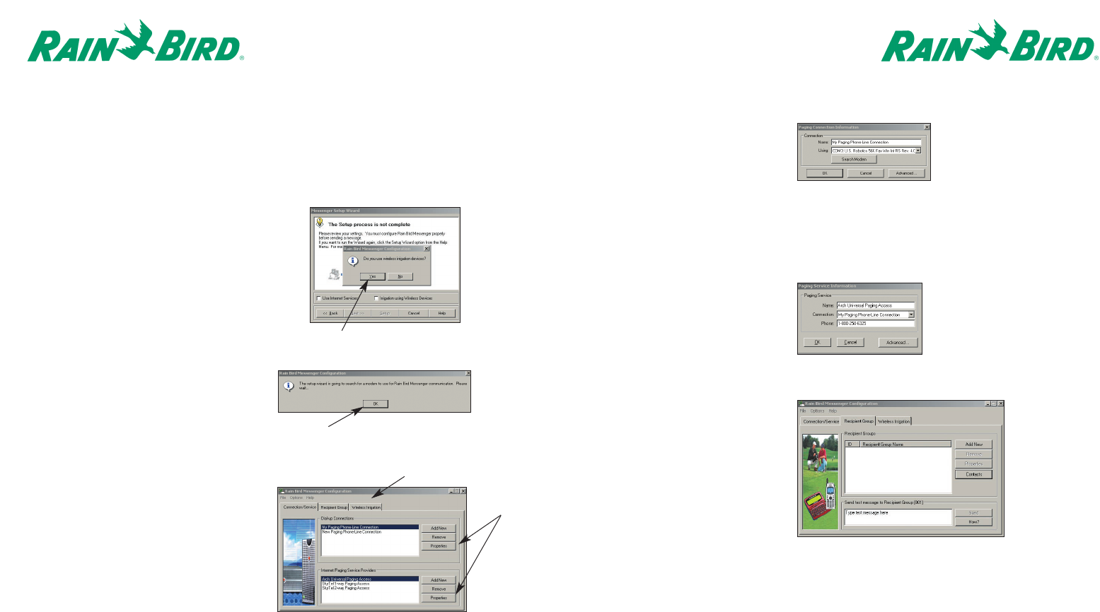
9. Confirm the COM port and modem
information is correct and click OK.
Next, highlight the paging service
to be used (either Arch or SkyTel)
and then click on the properties
button for Internet/Paging Service
Providers.
10. Confirm the information is correct
and click OK.
Page 14
6. Four more screens will follow. Please click next, install, or finish on these screens. These
screens are completing the set-up Wizard for Rain Bird Messenger. If you do not have MicroSoft
2.5 Data Components on your hard drive then they will also be installed at this time.
7. The first few set-up screens indicate the
amount of time it will take to complete the
set-up. Please click Yes/OK for these screens.
B.
A.
C.
Click Yes
Click OK
Tabs
Properties
8. This screen will open after your
modem is located. The screen will
have the information already listed
on it.
Highlight “My Paging Phone-Line
Connection”and click on properties
for Dial-Up connections.
11. Next click on the Tab labeled
Recipient Group. To set up a
Recipient Group, click on the
Add New Button.
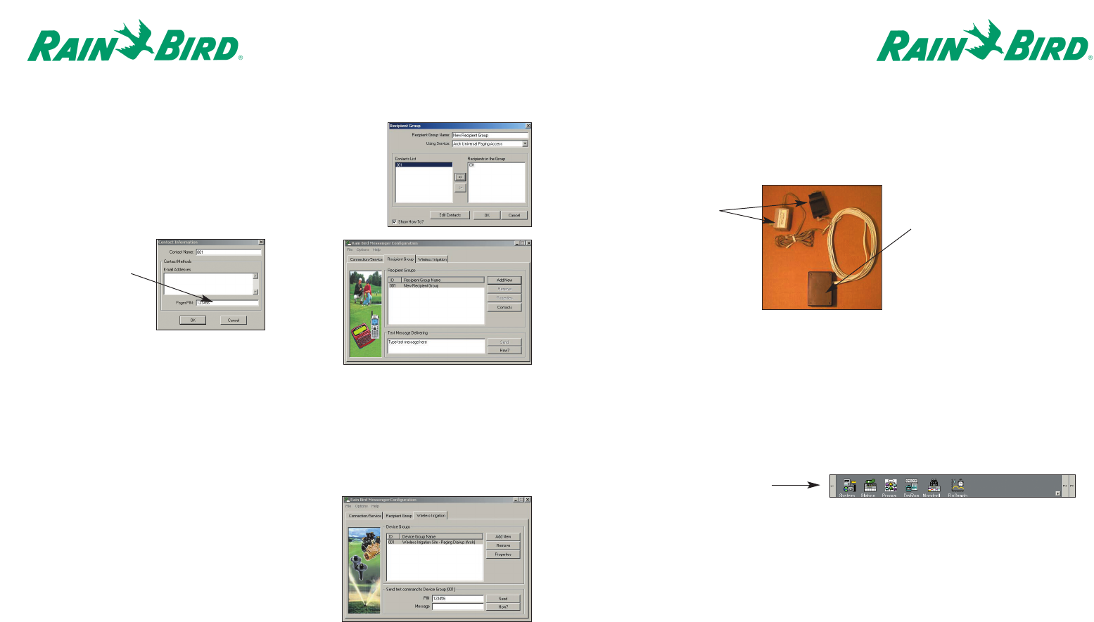
Page 17
THE LISTENING DEVICE
The Listening Device connects to the computer and “listens”for the specific rotor data information
unique to each individual site.
The Listening Device connects to an available COM port on the computer via a nine pin connector.
The unit will be pre-programmed by Rain Bird.
The purpose of the Listening Device unit is to “hear”the information unique to the course when a
page is sent by the computer and then received by the rotor. This is done through the
Cirrus/Nimbus II/Stratus II™Central Control programs version 3.0.x or higher.
Following are the steps to complete within the Cirrus/NimbusII/StratusII software program(s) to set
up the unit:
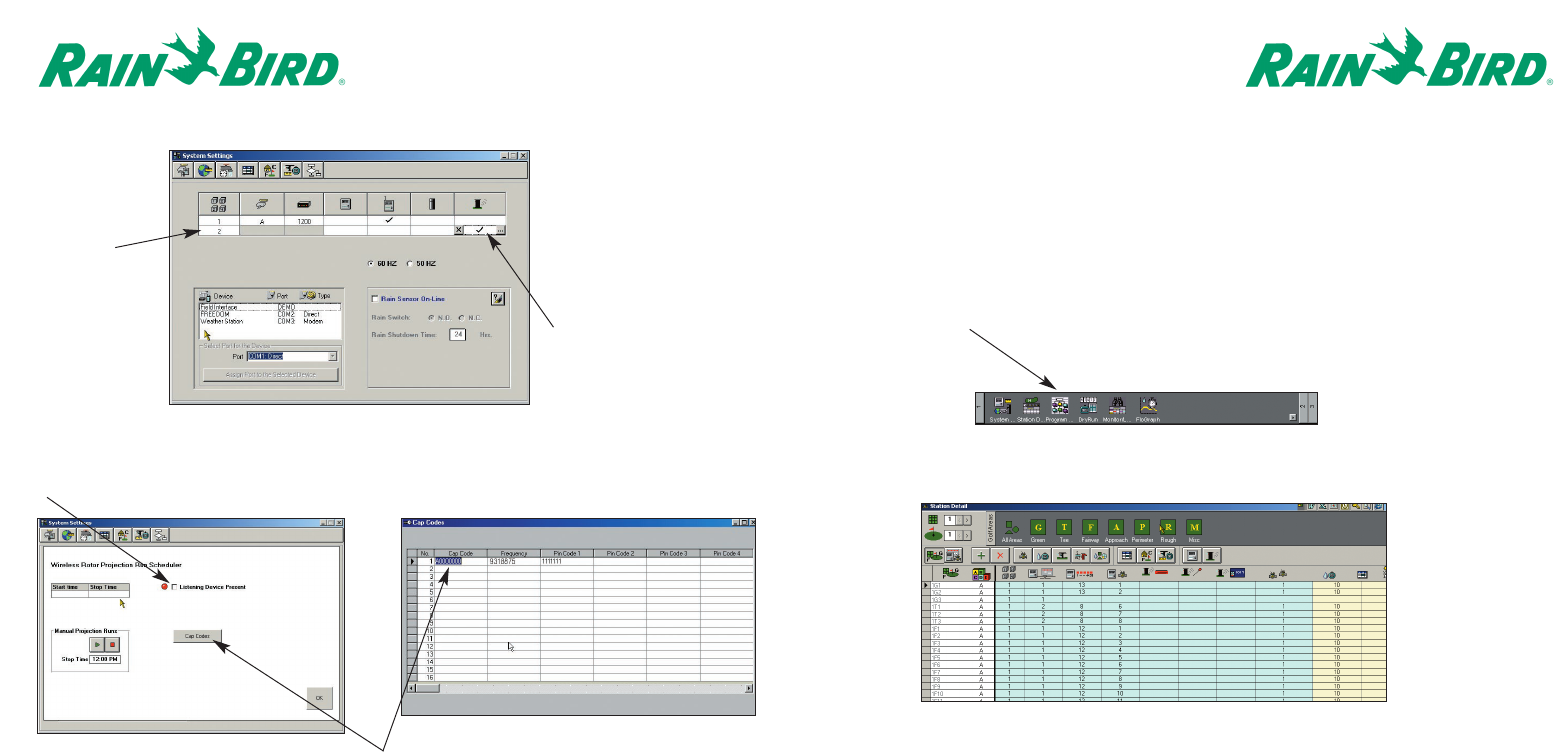
1. Open the System Settings Tables.
2. Click in the cell under the wireless rotor symbol. Always use the 2nd row down when setting up
the wireless rotor. See picture on page 18.
Page 16
12. Click on the drop down arrow and select the Pager Service to be
used. Click on Edit Contacts in order to enter the 001 in your
contact list. Once 001 is in the contact list, make sure it is
highlighted and click on the arrow pointing to the Recipient Group
window to place it in there as well. Click OK.
13. Click on the Wireless Irrigation Tab.
Please note that the Wireless Group
(001) is already listed.
The Messenger Pager Set-Up is
complete. Not every screen was
captured.
Please contact your Rain Bird representative for
further assistance with Messenger set-Up process.
Enter the PIN
Number specific
for your course
This is a
completed
Recipient
Group.
9-pin connector and
external transformer
Listening Device unit with a 15’
extension cable, which allows
the unit to be mounted away
from the computer.
Page 19
STATION DETAIL TABLE CONFIGURATION
Each of the wireless rotors must be configured within the station detail table of
Cirrus/Nimbus II/Stratus II™Central Control software in order to operate.
The table provides all pertinent data entered in relation to each rotor and its location.
This feature is accessed by clicking on the “Station Detail”icon located on the right side of the
“Front Office”screen.
Page 18
3. After checking the box as indicated in Step 2, the following screen will appear:
Check in the Listening Device Present box to complete the setup of the listening device.
With the Listening Device unit active, the Central Control software will record the irrigation time(s) for
each wireless rotor.
Click in the square below the
wireless rotor symbol then
click on the square with the
(…)
Click on the Cap Codes Button to input the CapCode,
Frequency and Pin Code for the course.
2nd Row
The “Station Detail”table will be displayed as shown below.
To add the wireless rotor information, click on the designated area and then click on the plus symbol.
Page 20
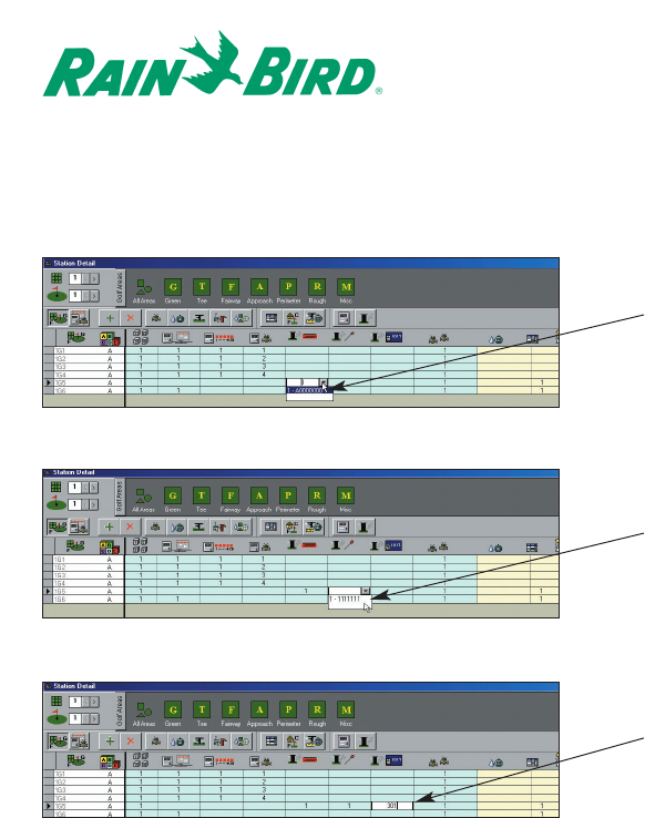
Input the specific information as shown below.
The drop-down table information is input as shown on page 14.
Programming the Wireless Rotor
To create irrigation programs using the Cirrus/NimbusII/StratusII Central Control software, please
refer to the operations manual for the specific Central Control software purchased.
Enter
Capcode
Enter
PIN
Enter
Passcode