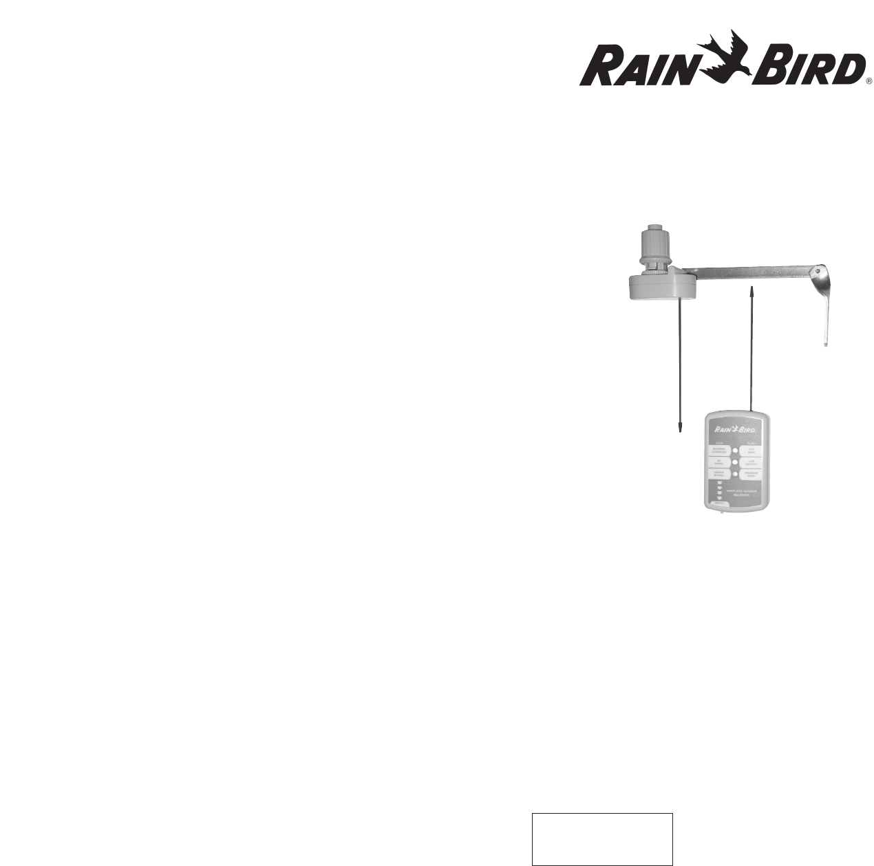
Rain Bird Controls Division WST Wireless Rain Sensor User Manual WRC Rain r13
Rain Bird Corporation - Controls Mfg. Division Wireless Rain Sensor WRC Rain r13
User Manual
Rain Bird Sales, Inc
Commercial Division
6640 S. Bonney Avenue
Tucson, AZ 85706 USA
Phone: (520) 434-6200
Fax: (520) 434-6246
Specification Hotline
(USA and Canada only):
1-800-458-3005
Rain Bird Sales, Inc
Contractor Division
970 West Sierra Madre Avenue
Azusa, CA 91702 USA
Phone: (626) 812-3400
Fax: (626) 812-3411
Technical Assistance
(USA and Canada only):
1-800-247-3782
Wireless Rain
and
Wireless Rain/Freeze Sensor
Installation and Operating Instructions for:
WRC: Wireless Rain Sensor Combo
WRT: Wireless Rain Sensor Transmitter
WSR: Wireless Rain Sensor Receiver
WRFC: Wireless Rain and Freeze Sensor Combo
WRFT: Wireless Rain and Freeze Sensor Transmitter
7/03 635927
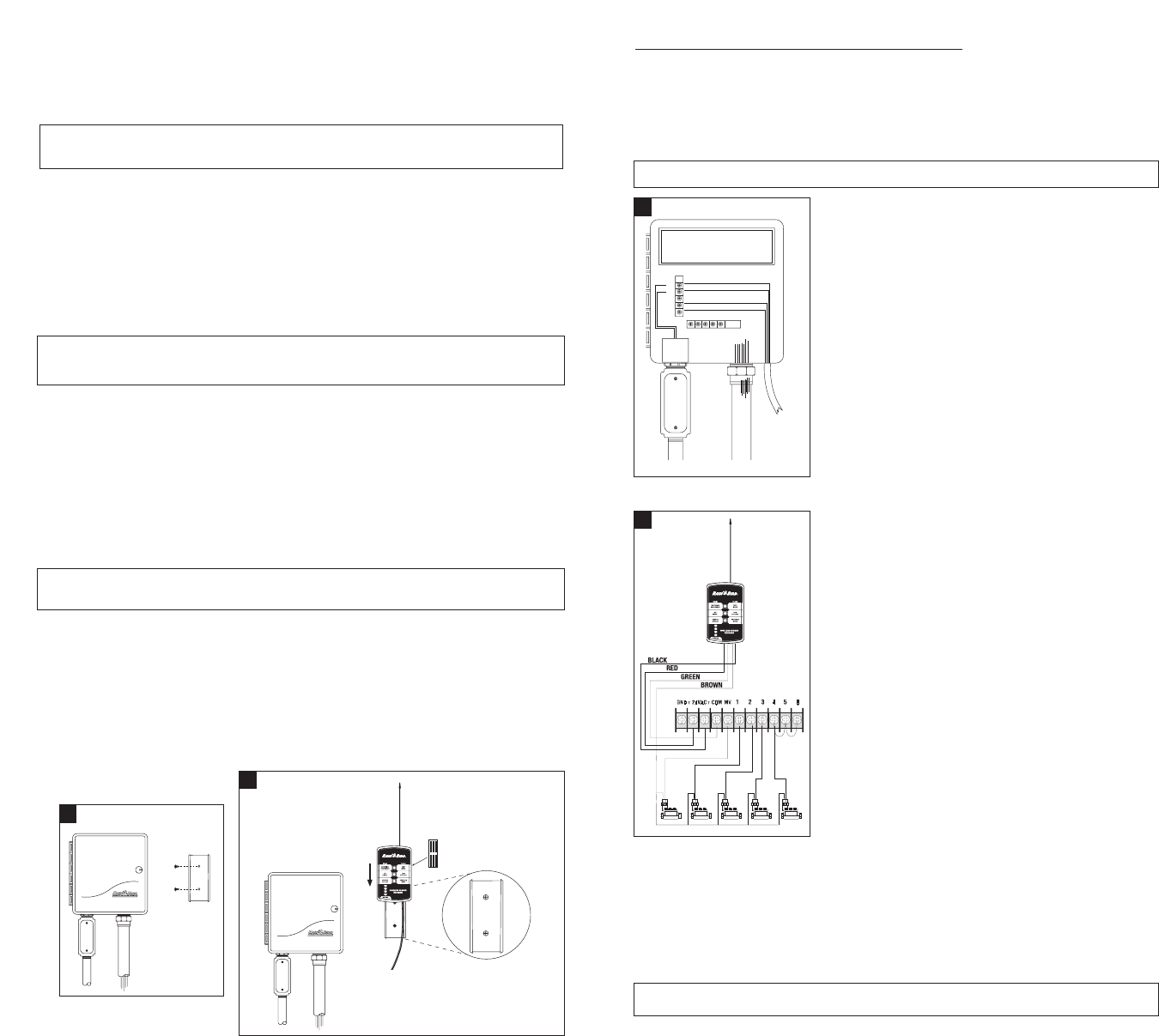
Wireless Rain and Freeze Sensor Wiring
Important! Before connecting wires, you must determine whether your controller uses
“Normally Open” or “Normally Closed” wiring for sensors.
All Rain Bird controllers, and most other manufacturers’ controllers, are installed using a
“Normally Closed” wiring method.
Normally Closed Installation
Note: The lead wire labeled “NO” is not used with this installation method.
Controllers With Sensor Input
Many modern controllers (such as Rain Bird’s E Class,
ESP-LX+, and ESP-MC) include built-in terminals for
sensor input. Dedicated terminals are usually labeled
“sensor” or “SN” on the controller’s terminal strip. See
Illustration 3.
1. Connect the Red and Black leads to the two 24VAC
terminals on your controller. (It is not important which
wire goes to which terminal.)
2. To connect the Rain and Freeze Sensor, remove the
jumper wire (if present) from the controller’s sensor
terminals.
3. Connect the Green lead and the Brown lead to the
Sensor Terminals on your controller.
Controllers Without Sensor Input
Use the procedure below if your controller does NOT have
dedicated sensor terminals. See Illustration 4.
1. Connect the Red and Black leads to the 24 VAC
terminals on your controller.
2. Disconnect the valve common wire from the common
terminal (“C” or “COM”) on the controller’s terminal
strip. Connect the valve common wire to the green
lead on the Sensor Receiver.
3. Connect the Brown lead to the “COM” terminal on the
controller’s terminal strip.
Normally Open Installation
Some non-Rain Bird controllers require rain sensors to be installed “Normally Open”
(“NO”). In this case, substitute the White Lead for the Brown Lead in the installation for a
“Normally Closed” (“NC”) installation (above). Be sure to consult with the controller
manufacturer’s manual to determine the appropriate procedure for connecting the Rain
Sensor to your controller.
Note: In this case, the brown wire will not be used.
WRS-100 Wireless Rain Sensor 2
Wireless Rain and Freeze Sensor
The Wireless Rain Sensor automatically monitors rainfall and shuts off your sprinklers to
prevent unnecessary watering. Rain/Freeze Transmitter will also prevent watering in
freezing conditions.
Note: The Wireless Rain Sensor is a low-voltage device compatible with all 24 volt
alternating current (VAC) control circuits and 24 VAC pump start relays.
The Wireless Rain and Freeze Sensor is a very sophisticated Sensor Transmitter and
Receiver system designed to work with all 24 volt alternating current (VAC) control
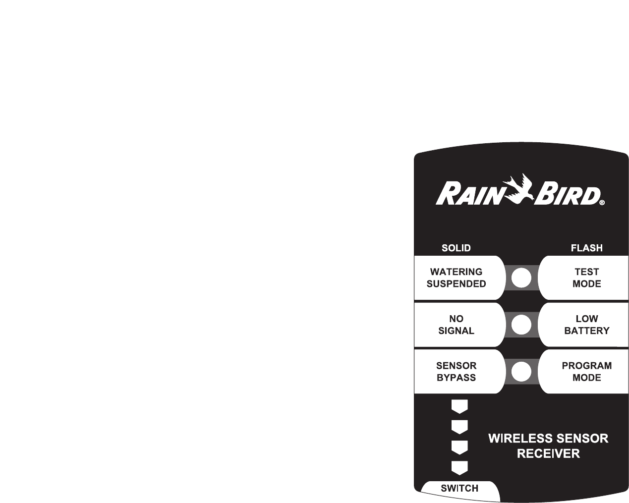
circuits and 24 VAC pump start relay circuits. The Receiver has three Light Emitting
Diodes (LEDs). Each LED can indicate two conditions. If the LED is solid then the
condition labeled on the left is occurring. If the LED is blinking the condition labeled
on the right has taken place. These are explained on page 7.
1. Installation
Note: Follow the installation instructions carefully and install the unit only in full compliance
with the National Electrical Code (NEC) or your local electrical code.
There are two components of the Wireless Rain Sensor product, the Sensor Transmitter and
the Receiver.
Important!: Begin by installing the Receiver and test the two components (transmitter and
receiver) side by side before mounting the Sensor Transmitter.
Wireless Rain and Freeze Sensor Receiver Mounting
1. Select a place near your controller where you will install the Receiver. Ensure that there
will be room for the receiver antenna and that the leads will reach to the sensor
connection on your controller (approximately 24 inches).
Note: The Receiver unit is weather resistant and is suitable for mounting near an outdoor
controller.
2. Secure the bracket to the wall near your controller with appropriate fasteners. Be sure to
install the bracket with the flanges facing out away from the wall. See Illustration 1.
3. Slide the water resistant receiver unit down onto the mounting bracket.
See Illustration 2.
4. Attach the red “Notice” sticker to your automated irrigation system control panel.
5. Attach the gray “Receiver” memory sticker to the side of the Receiver.
1 WRS Wireless Rain and Freeze Sensor
1
Mount Receiver
bracket near
existing
controller.
2
Slide Receiver
down on to the
mounting
bracket.
Receiver
Memory
Record
Install bracket
with flanges
facing out
from the wall.
COM 1 2 3MV
SENSOR
TRANSFORMER
SENSOR
GND
24V
24V RED
BLACK
GREEN
BROWN
ORANGE
ORANGE
TO
RECEIVE
R
3
4
Testing the Transmitter and Receiver Pair
If you bought the Transmitter and
Receiver together, they were
programmed at the factory to
work together. If you purchased
them separately, or, if the
following test procedure doesn’t
work properly, it may be
necessary to program the
receiver to work with the
transmitter. Use the following
procedure to test the two units
together. See Illustration 5.
1. Push and hold the pin for a few seconds on the top of the Sensor Transmitter.
2. If the Receiver detects the signal, the Red LED will begin to indicate “Watering
Suspended”.
3. You can release the Transmit button and continue with the installation.
SENSOR
BYPASS
Watering
Suspended
WATERING SUSPENDED
BY SENSOR
5Test Sensor Transmitter with Receiver
Select an appropriate mounting location as described
above. Drive two mounting screws through the
mounting holes in the mounting bracket. Use
fasteners appropriate for the mounting surface
(wood, tile, masonry, etc.).
Be sure to test the reception of the signal from the
sensor, in this location, to the receiver using this procedure.
1. Push and hold the Transmitter button for at least four (4) seconds (but not more than
14 seconds).
2. The Sensor Transmitter will send a signal with lower than normal power.
3. If the Receiver detects the signal, the Red LED will begin flashing for a duration of 2.5
minutes. This allows a single installer time to return to the Receiver to verify the signal
was received. If the LED is flashing, the selected Transmitter location is within range.
2. Operation
Set Rainfall Setting
The rainfall setting determines the amount of rainfall needed to prevent your irrigation
system from watering. You can adjust the rainfall setting from 1⁄8" to 3⁄4" (5mm to 20mm).
The ideal rainfall setting for your location depends on soil type, humidity, amount of direct
sunlight the sensor receives and frequency and amount of rainfall. The table below gives
some guidelines to help determine the appropriate rainfall setting. (See table)
Note: At the 1⁄8" or 5mm setting , a very light rainfall will activate the sensor and suspend
watering. The 1⁄8" or 5mm rainfall setting is not recommended in areas with high humidity.
To set the rainfall setting, turn the sensor dial cap until the desired rainfall setting lines up
with the arrow on the sensor body (A), as shown in Illustration 8.
WRS Wireless Rain and Freeze Sensor 4
Programming the Transmitter and Receiver Pair
If a Receiver unit does not successfully receive a Sensor Transmitter signal, use the
following procedure to program the Receiver to recognize the Sensor Transmitter. It is
possible to program a Receiver to receive signals from up to five Sensor Transmitters.
This allows your Receiver to work with multiple sensors that may be used to interrupt
watering.
1. Press and hold the bypass switch on the Receiver button until the Green LED begins
to blink rapidly, then release (Green LED will then begin to blink approximately once
per second).
2. Activate the transmitter (by pushing the pin on the top of the Sensor Transmitter)
until a clicking noise is heard from the receiver and the Red LED indicates
“Watering Suspended”.
3. If more than one click is heard, this means multiple transmitters are programmed into
this Receiver unit. The number of clicks will indicate how many of five locations have
been programmed.
4. To exit the Program Mode prior to activating the Transmitter, push and release the
Receiver button. If the Transmitter is not activated for thirty (30) seconds after the
Receiver is in Program Mode, the Receiver will return to Sensor Bypass Mode.
Selecting a Location for the Sensor Transmitter
Select a mounting location where the rain-sensing head will receive direct rainfall. Make
sure the head extends beyond the roof line, tree limbs, and any other obstructions. Install
the Sensor Transmitter in an area that receives as much rain and sunlight as the grass.
Be sure to mount the sensor above spray from
sprinklers. Avoid mounting locations such as those
shown in Illustration 6.
Be sure that the sensor is located within range of the
receiver portion of the Wireless Rain Sensor system.
See “Testing the System”section.
3 WRS Wireless Rain and Freeze Sensor
6
8Irrigation site conditions Rainfall setting
• Dry climate/low humidity 1⁄8" to 1⁄4"
(5mm to 10mm).
• Infrequent, light rains
• Sensor receives long periods
of direct sunlight
• Clay-type soils
• Moist climate/high humidity 1⁄2" to 3⁄4"
(15mm to 20mm).
• Frequent, heavy rains
• Sensor mounted in a mostly
shady area
• Sandy soils
Sensor Transmitter Mounting and
Low Power Test
This procedure allows a single installer to mount
and test the Sensor Transmitter and Receiver for
communication. See Illustration 7.
The Low Power Test helps to ensure that the
Wireless Sensor will continue to operate even
under conditions of radio interference or
weakening batteries.
7
5. Functional Mode Summary
Monitor
The Monitor Mode is the normal mode of operation once the Transmitter and Receiver
unit(s) have been installed. While the transmitter is in Monitor Mode, it will transmit a
signal on a change of state (such as rain received) or at a fixed interval to confirm that a
communication link still exists. While the Receiver is in Monitor Mode, it will continually
listen for signals from the Transmitter(s).
Program
The Program Mode allows for a Transmitter to be programmed into a receiver to allow
one-way communication. Each Receiver is capable of holding five (5) Transmitters in its
memory.
Press and hold the Bypass Switch on the Receiver until the Green LED begins to blink
rapidly, then release (Green LED will then begin to blink approximately once per second).
To program the Transmitter into the Receiver, activate the Transmitter by holding down the
pin at the top of the Sensor Transmitter until a clicking noise is heard from the Receiver.
The number of clicks will indicate which one of five locations the Transmitter has been
programmed into. To exit the Program Mode prior to activating the Transmitter, push and
release the Receiver bypass button. If the Transmitter is not activated for thirty (30) seconds
once the Receiver is in Program Mode, the Receiver will return to Sensor Bypass Mode.
Test
The Test Mode allows for the installation site to be tested for signal reception. Once in
Test Mode, the Transmitter will send a signal to the Receiver at one half the normal signal
strength. After sending the signal, the Transmitter will return to the Monitor Mode.
Typically, this mode is only utilized during installation.
Push and hold the Transmitter button for at least four (4) seconds but not longer than
14 seconds. The Transmitter will send a signal at the test mode signal strength. If the
Receiver detects the signal, the Red LED will begin flashing for a duration of two and a
half (2.5) minutes.
Bypass
The Bypass Mode allows for the irrigation system to operate independently from the
Wireless Rain Sensor. Regardless of whether the Wireless Rain Sensor is in the Watering
Suspended state due to rain or freeze, the irrigation system will operate normally when in
the Bypass Mode. You can toggle back and forth between Bypass and Non-Bypass. A
Bypassed state with Watering Suspended will reset back to the Monitor Mode once the
disks dry out.
Momentarily push and release the Receiver button to toggle between the Bypass and
Monitor Modes. The Receiver is in Bypass Mode when the Green LED is solid. Note: If the
Receiver button is depressed longer than four (4) seconds prior to releasing, the Receiver
will enter the Program Mode.
WRS Wireless Rain and Freeze Sensor 6
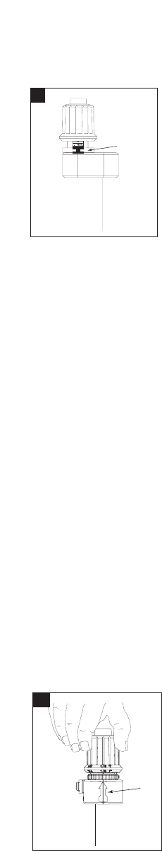
Set Vent Ring
The vent ring determines “drying time”– the length of time the sensor turns off irrigation
after a rainfall. For most installations, set the vent ring to the fully open position.
For some installations, such as sites where water pools after
rainfall, set the vent ring to a partially open position. This will
shut down the irrigation system a little longer after a rain.
To set the vent ring, turn the vent ring knob below the dial
cap to the desired position, as shown in Illustration 9.
3. Testing the System
It is recommended that you check the Transmitter and Receiver side by side prior to
mounting the Sensor. It is also recommended that the Low Power Test be completed
successfully.
Once installed, the completed system can be tested by turning on any controller irrigation
zone, verifying that zone does come on, and then pressing down on the Rain Sensor pin
located on the top of the dial cap. The irrigation system should stop watering within a few
seconds. If the system does not shut off, review the installation process to ensure the
system is correctly installed.
For assistance, call Rain Bird Technical Services at 800-247-3782 (USA and Canada only).
4. Maintenance
The Wireless Rain Sensor operates automatically and usually requires no regular
maintenance other than replacing the batteries in the Rain and Freeze Sensor
(Transmitter) every three (3) years. Replace the batteries with two Panasonic CR2032
3V or equivalent replacement. Rain Bird Part Number 651009 - CR2032 lithium battery.
In addition, the fibrous disks inside the Transmitter dial cap sometimes become
contaminated with debris or insects. If this happens, use the following procedure to
clean the Rain Sensor.
1. Turn the dial cap to the 3⁄4" rainfall setting, as shown in Illustration 10.
2. Press the tab labeled “Press”on the side of the sensor body. Then turn the dial cap
about 1 and 1⁄4turns further to remove the cap from the sensor body.
3. Remove the plunger and disks from the sensor body, and wash them in clean water.
4. Reinstall the plunger and disks into the cap first, then screw the cap onto the sensor
body. Reset the rainfall setting to the desired position.
5 WRS Wireless Rain and Freeze Sensor
A
10
Vent Ring
9
WRS Wireless Rain and Freeze Sensor 8
Receiver LED Indications
Normal – ALL LEDs OFF
Watering Suspended
(Freeze or Rain) – RED SOLID LED
The Red LED becomes solid if the Transmitter is activated while the Receiver is in the
Bypass or Monitor Mode.
No Signal – YELLOW SOLID LED
The Transmitter retransmits its current state several times a day. If the Receiver does not
receive two consecutive transmissions, then the Yellow LED becomes solid to indicate a
loss of signal. The LED will turn off if the Transmitter becomes activated. Possible causes
include low batteries, radio frequency interference, and physical obstacles.
Sensor Bypass – GREEN SOLID LED
The Green LED becomes solid if the Receiver is put into the Bypass Mode. Until a change
of state is received from the Transmitter or the user toggles the Receiver back to Monitor
Mode, the irrigation system will operate independently from the WRS.
Test Mode – RED FLASHING LED
The Red LED flashes when the Receiver has successfully received the test signal from the
Transmitter. Once the test signal is received, the Receiver will continue to flash the Red
LED for two and a half (2.5) minutes. The flashing LED will turn off if the Receiver
changes mode.
Low Battery – YELLOW FLASHING LED
The expected life of the battery is 3 years. The yellow LED begins to flash when
approximately two and a half years of battery life have been depleted. Changing the
batteries will reset the low battery indicator.
Program Mode – GREEN FLASHING LED
When the Bypass Switch on the Receiver is held for more than three seconds, the Green
LED will begin to blink rapidly. If the button is then released, the Receiver will enter the
Program Mode, which is indicated by the Green LED blinking approximately once per
second. The Green LED will turn off if the Receiver Bypass Switch is pushed again or the
Transmitter becomes activated.
7 WRS Wireless Rain and Freeze Sensor

Notes: Product Specifications
Transmitter
Size: 3 x 2 x 9 inches (8 x 5 x 23 mm)
Batteries: 2 ea. #CR2032
Frequency: 433.92 MHz
Receiver
Size: 2 3⁄4x 11⁄2x 9 inches (7 x 4 x 23 mm)
Power: 24 VAC, 0.1 Amp, 125 VAC, 30 VDC
Relay: SPDT, 3 Amp, 125 VAC, NO, NC, COM
Connections: 24 VAC, 24 VAC, NO, NC, COM
This device complies with part 15 of the FCC Rules. Operation is subject to the
following two conditions:
(1) This device may not cause harmful interference, and
(2) This device must accept any interference received, including interference that may
cause undesired operation.