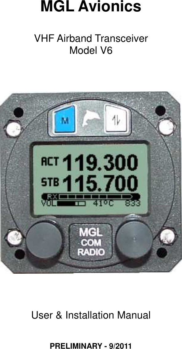
Rainbow Aircraft V6 AVIATION VHF AM TRANSCEIVER User Manual V6 Transceiver Manual 2011 09 20
Rainbow Aircraft, Inc. AVIATION VHF AM TRANSCEIVER V6 Transceiver Manual 2011 09 20
UserManual.wiki
>
Rainbow Aircraft
>
V6 User Manual
Users Manual
Navigation menu
Upload a User Manual
Namespaces
Wiki Guide
HTML
PDF
Info
Views
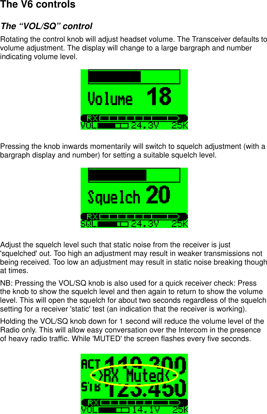
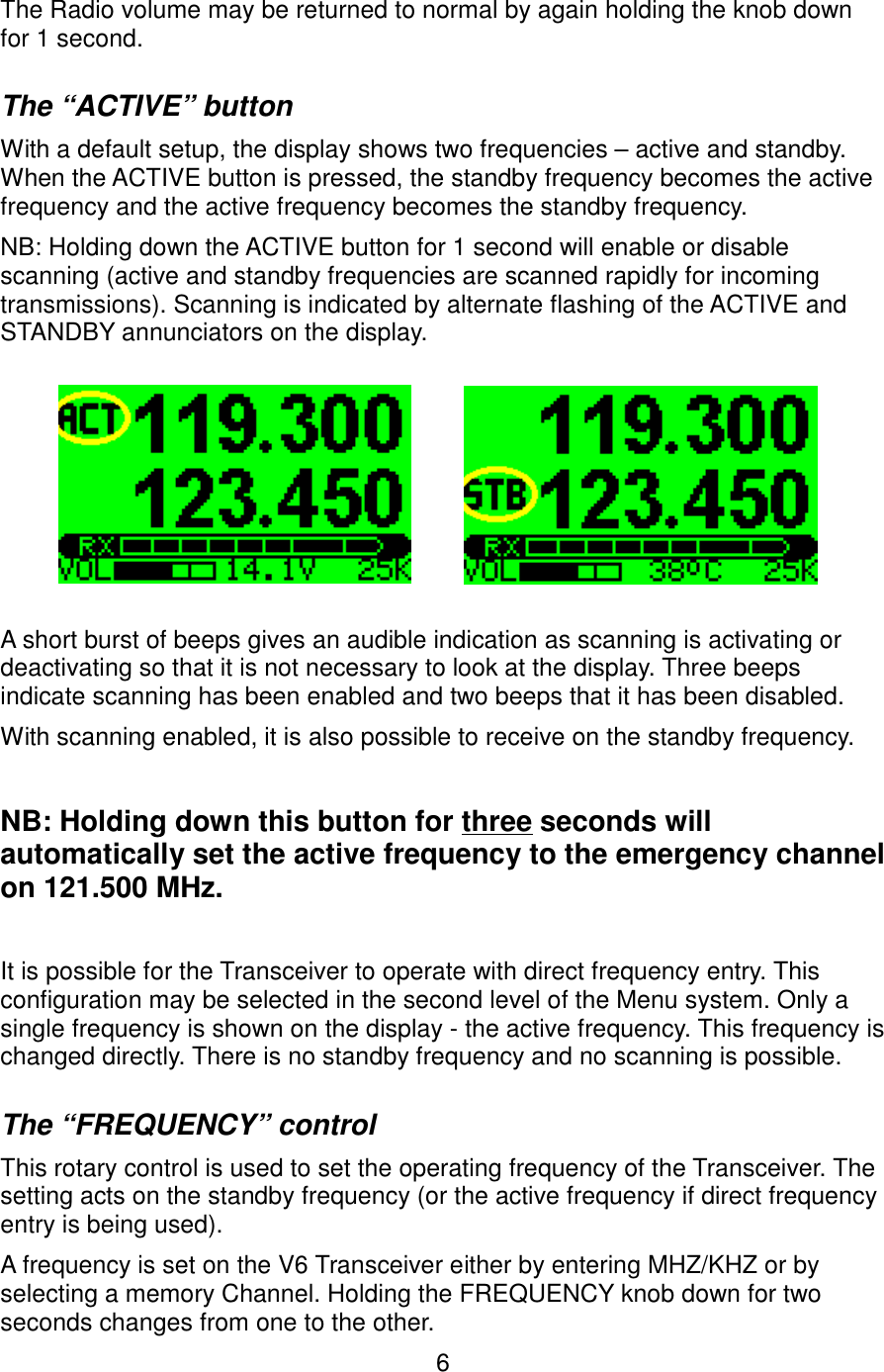
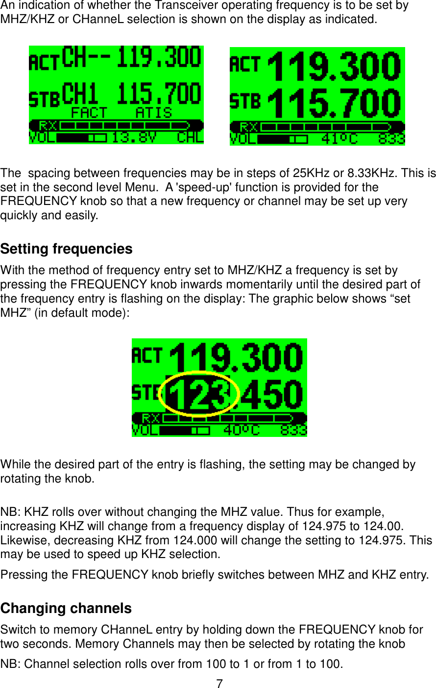
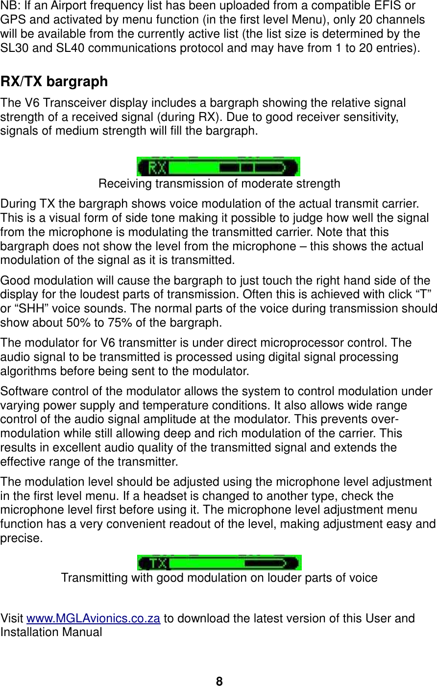
User Manual
Discussion / Help
Navigation