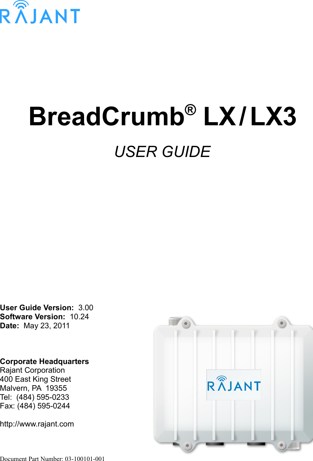
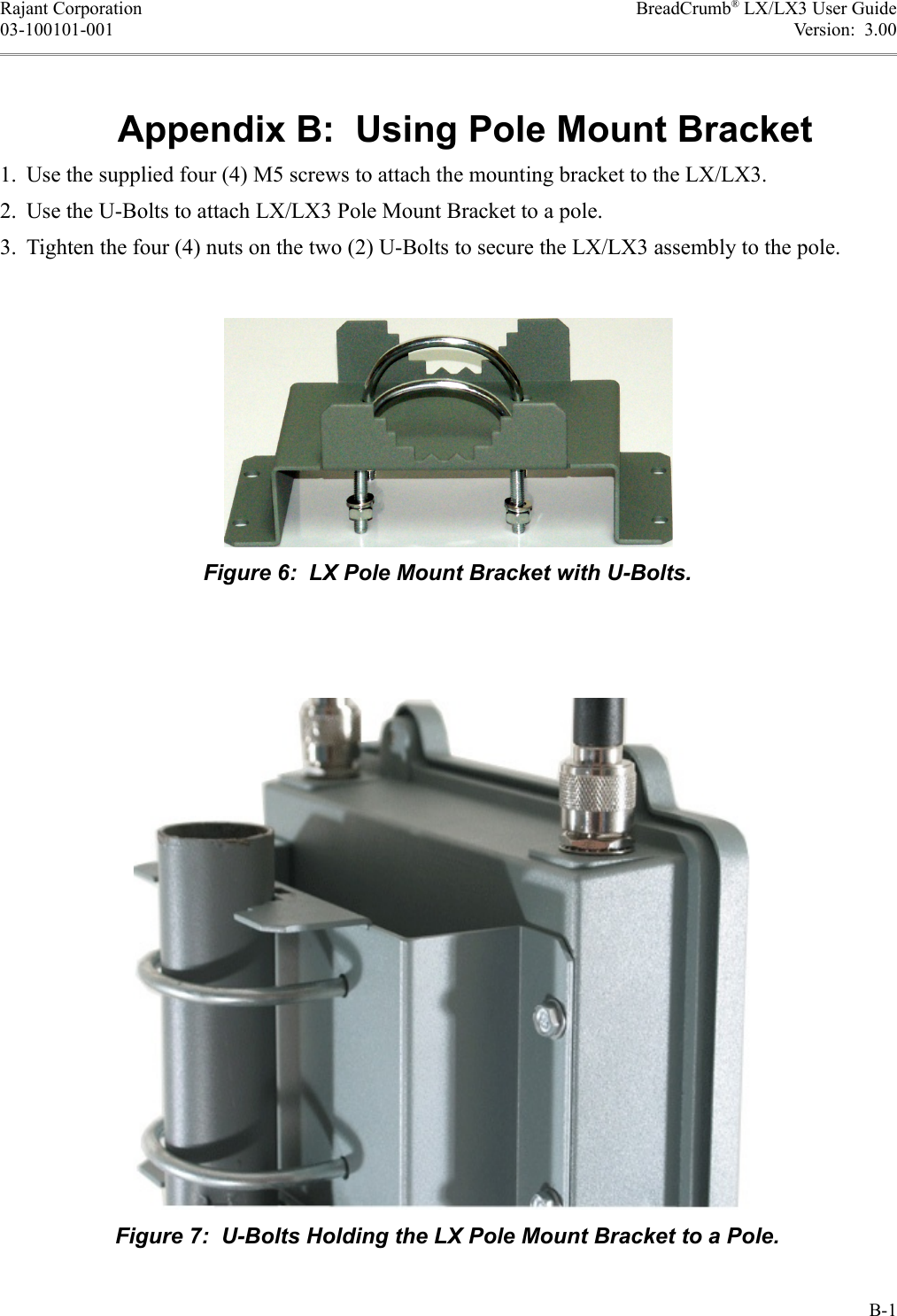
Rajant LX3-2209D Digital Transmission System, Long Range Mobile Broadband Communications Device User Manual

Rajant Corporation Digital Transmission System, Long Range Mobile Broadband Communications Device

User Manual

BreadCrumb® LX / LX3USER GUIDEUser Guide Version:  3.00Software Version:  10.24Date:  May 23, 2011Corporate HeadquartersRajant Corporation400 East King StreetMalvern, PA  19355Tel:  (484) 595-0233Fax: (484) 595-0244http://www.rajant.comDocument Part Number: 03-100101-001
iiFCC Compliance StatementsThis equipment has been tested and found to comply with the limits for a Class A digital device, pursuant to Part 15 of the FCC Rules.  These limits are designed to provide reasonable protection against harmful interference when the equipment is operated in a commercial environment.  This equipment generates, uses, and can radiate radio frequency energy and, if not installed and used in accordance with this instruction manual, may cause harmful interference to radio communications. Operation of this equipment in a residential area is likely to cause harmful interference in which case the user will be required to correct the interference at their own expense.CAUTION: Changes or modifications not expressly approved by Rajant Corp. could void the user's authority to operate the equipment.WARNING: This equipment complies with the FCC RF radiation exposure limits set forth for an uncontrolled environment. This equipment should be installed and operated with a minimum distance of 30 centimeters between the radiator and all persons while the device is operating.This transmitter must not be co-located or operating in conjunction with any other antenna or transmitter.The antennas used for this transmitter must be installed to provide a separation distance of at least 30cm from all persons and must not be located or operating in conjunction with any other antenna or transmitter.IC Compliance Statements1) This Class A digital apparatus complies with Canadian ICES-003.Cet appareil numérique de la classe A est conforme à la norme NMB-003 du Canada.2) Under Industry Canada regulations, this radio transmitter may only operate using an antenna of a type and maximum (or lesser) gain approved for the transmitter by Industry Canada. To reduce potential radio interference to other users, the antenna type and its gain should be so chosen that the equivalent isotropically radiated power (e.i.r.p.) is not more than that necessary for successful communication.Conformément à la réglementation d'Industrie Canada, le présent émetteur radio peut fonctionner avec une antenne d'un type et d'un gain maximal (ou inférieur) approuvé pour l'émetteur par Industrie Canada. Dans le but de réduire les risques de brouillage radioélectrique à l'intention des autres utilisateurs, il faut choisir le type d'antenne et son gain de sorte que la puissance isotrope rayonnée équivalente (p.i.r.e.) ne dépasse pas l'intensité nécessaire à l'établissement d'une communication satisfaisante. 3) This radio transmitter has been approved by Industry Canada to operate with the antenna types listed below with the maximum permissible gain and required antenna impedance for each antenna
type indicated. Antenna types not included in this list, having a gain greater than the maximum gain indicated for that type, are strictly prohibited for use with this device.Le présent émetteur radio (identifier le dispositif par son numéro de certification ou son numéro de modèle s'il fait partie du matériel de catégorie I) a été approuvé par Industrie Canada pour fonctionner avec les types d'antenne énumérés ci-dessous et ayant un gain admissible maximal et l'impédance requise pour chaque type d'antenne. Les types d'antenne non inclus dans cette liste, ou dont le gain est supérieur au gain maximal indiqué, sont strictement interdits pour l'exploitation de l'émetteur.Frequency Range (MHz)Antenna Gain (dBi) Antenna Type Impedance (Ohms)5745 - 5825 6 Omni-directional 502412 - 2462 5 Omni-directional 50907 - 922 5 Omni-directional 504942.5 - 4987.5 6 Omni-directional 504) This device complies with Industry Canada licence-exempt RSS standard(s). Operation is subject to the following two conditions: (1) this device may not cause interference, and (2) this device must accept any interference, including interference that may cause undesired operation of the device.Le présent appareil est conforme aux CNR d'Industrie Canada applicables aux appareils radio exempts de licence. L'exploitation est autorisée aux deux conditions suivantes : (1) l'appareil ne doit pas produire de brouillage, et (2) l'utilisateur de l'appareil doit accepter tout brouillage radioélectrique subi, même si le brouillage est susceptible d'en compromettre le fonctionnement.5) High-power radars are allocated as primary users (i.e. priority users) of the bands 5250-5350 MHz and 5650-5850 MHz and that these radars could cause interference and/or damage to LE-LAN devices.De plus, les utilisateurs devraient aussi être avisés que les utilisateurs de radars de haute puissance sont désignés utilisateurs principaux (c.-à-d., qu’ils ont la priorité) pour les bandes 5 250-5 350 MHz et 5 650-5 850 MHz et que ces radars pourraient causer du brouillage et/ou des dommages aux dispositifs LAN-EL.
Copyright StatementYou may use the software provided with the products only on personal computers owned by the purchasing individual or entity, and may not use, load, or run any such software on any network or in any type of service bureau, time-sharing operation, or non-purchasing individual or entity's equipment.BCAdmin and BCAPI are trademarks; Rajant, the Rajant logo, BreadCrumb, Instamesh, BC|Commander, and  Bring Your Network with You! are registered trademarks of Rajant Corp. in the United States and certain other countries.BreadCrumb® LX / LX3 User GuideCopyright © 2007–2011 Rajant Corp.  All rights reserved.iv
Rajant Corporation BreadCrumb® LX/LX3 User Guide03-100101-001 Version:  3.00Table of ContentsFCC Compliance Statements.........................................................................................iiIC Compliance Statements.............................................................................................iiCopyright Statement......................................................................................................ivPreface..................................................................................................................................viiPurpose and Scope...........................................................................................................viiUser Information................................................................................................................viiRelated Documentation.....................................................................................................vii 1 Introduction to BreadCrumbs..........................................................................................1 1.1 What is a BreadCrumb?...............................................................................................1 1.2 Mobility through Meshing.............................................................................................2 1.2.1 Mesh – A Definition...............................................................................................2 1.2.2 BreadCrumb Mesh Connections..........................................................................2 2 Description of a BreadCrumb LX/LX3.............................................................................5 2.1 Radios..........................................................................................................................5 2.2 Enclosure.....................................................................................................................8 2.3 Antenna Connectors....................................................................................................9 2.4 Power and Ethernet Connectors................................................................................11 2.5 Status LED.................................................................................................................12 2.6 LED Configuration / Zeroize Keys and Restore Factory Defaults Switch ................13 2.6.1 LED Configuration..............................................................................................13 2.6.2 Zeroize Keys and Restore Factory Defaults.......................................................14 3 Using BC|Commander....................................................................................................17 4 Deploying the BreadCrumb Wireless Network............................................................19 4.1 Addressing.................................................................................................................19 4.1.1 BreadCrumb Device Addresses.........................................................................19 4.1.2 DHCP..................................................................................................................19 4.2 Channel Assignments................................................................................................19 4.3 Physical Placement and other Considerations..........................................................20 4.3.1 Line-of-Sight.......................................................................................................20 4.3.2 Distance..............................................................................................................20 4.3.3 Weather..............................................................................................................21 4.3.4 Interference.........................................................................................................21 4.3.5 Placement of BCWN Components.....................................................................22 4.4 Deployment Guidelines and Methodology.................................................................22 4.4.1 Deployment Guidelines......................................................................................22 4.4.2 Deployment Methodology...................................................................................23v
BreadCrumb® LX/LX3 User Guide Rajant CorporationVersion:  3.00 03-100101-001 5 BreadCrumb LX/LX3 Firmware Upgrade......................................................................25 5.1 Over The Air Firmware Upgrade................................................................................25 5.2 USB Firmware Upgrade.............................................................................................25 6 Troubleshooting..............................................................................................................27 6.1 Sporadic Network Connectivity..................................................................................27 6.2 BreadCrumb Device Cannot Connect to BCWN.......................................................28 6.3 BreadCrumb Power and Start-Up Issues..................................................................28Appendix A:  Error and Warning Codes..........................................................................A-1Appendix B:  Using Pole Mount Bracket........................................................................B-1List of FiguresFigure 1: All BreadCrumbs use the same ESSID...................................................................3Figure 2: ESSID of BreadCrumb C changes to "lonely.".........................................................3Figure 3:  BreadCrumb LX/LX3 Enclosure Features (Top-Front Side)...................................8Figure 4:  BreadCrumb LX/LX3 Enclosure Features (Bottom-Rear Side)..............................9Figure 5:  BreadCrumb LX/LX3 Ethernet and Passive PoE Connections............................12Figure 6:  LX Pole Mount Bracket with U-Bolts...................................................................B-1Figure 7:  U-Bolts Holding the LX Pole Mount Bracket to a Pole........................................B-1List of TablesTable 1:  2.4 GHz Radio Channel and Frequencies...............................................................5Table 2:  900 MHz Radio Channel and Frequencies..............................................................6Table 3:  5 GHz Radio Channel and Frequencies...................................................................6Table 4:  4.9 GHz Radio Channel and Frequencies...............................................................7Table 5:  BreadCrumb LX Radio/Antenna Configurations....................................................10Table 6:  BreadCrumb LX3 Radio/Antenna Configurations..................................................10Table 7:  Status LED Color Codes........................................................................................13Table 8:  Default and alternate display states of the Status LED..........................................14Table 9:  Default Channel Assignments................................................................................20Table 10:  Sporadic Network Connectivity Issues.................................................................27Table 11:  BreadCrumb to BCWN Connectivity Issues.........................................................28Table 12:  BreadCrumb Power and Start-Up Issues.............................................................28vi
Rajant Corporation BreadCrumb® LX/LX3 User Guide03-100101-001 Version:  3.00PrefacePurpose and ScopeThis manual provides information and guidance to all personnel who are involved with and use Rajant Corporation’s BreadCrumb LX/LX3 products.This manual begins with an introduction to the BreadCrumb Wireless Network (BCWN).  It then characterizes the features of the BreadCrumb LX/LX3.  Finally, it describes common deployment scenarios and provides concise step-by-step instructions for each scenario.NoteThroughout this document, unless otherwise stated, the term LX is used to refer to Rajant BreadCrumb LX, the term LX3 is used to refer to Rajant BreadCrumb LX3, and the term BreadCrumb is used to refer to both Rajant BreadCrumb LX and Rajant Breadcrumb LX3.User InformationThe user of this manual is encouraged to submit comments and recommended changes to improve this manual. Please send any comments or changes to support@rajant.com.  Be sure to include the version number of the manual you are using and please provide the page numbers related to your comments wherever possibleRelated DocumentationFor additional information, refer to these documents:●Rajant BC|Commander® User Guide:  This document contains information on the BC|Commander management application, which is used to configure BreadCrumbs before or during a deployment.●BreadCrumb® Video Guide●Rajant Troubleshooting Range User Guide●RF Component Installation and Verification in BreadCrumb® Networksvii
Rajant Corporation BreadCrumb® LX/LX3 User Guide03-100101-001 Version:  3.00 1  Introduction to BreadCrumbsRajant Corporation's (http://www.rajant.com) BreadCrumbs utilize the 802.11 wireless networking standards to form a wireless mesh network.  The network is mobile, self-integrating, self-meshing, self-healing, and secure.  The focus is on flexibility, adaptability, and simplicity.The BreadCrumb Wireless Network (BCWN) is intended for rapid deployment of a broadband wireless network into a situation or “hot zone.”  The network can be deployed as a stand-alone wireless network, or bridged to another network (such as the Internet) utilizing available reach-back communication links (such as a DSL, cable, or satellite modem).BreadCrumbs provide high bandwidth for applications to stream video, audio as well as data over large distances.  The network traffic can be secured by using different security features offered by the BCWN.  This makes the network optimal for tactical deployments as well as emergency response situations since it offers robustness, stability and ease of setup in mission critical activities. 1.1  What is a BreadCrumb?A BreadCrumb is an IEEE 802.11 (Wi-Fi) and Ethernet compatible networking device which has the capacity to connect to other BreadCrumbs or networking devices to form a BreadCrumb network.  A BreadCrumb is specifically designed for the following scenarios:Temporary Wireless NetworksNetworks that must be established quickly and with minimal effort for short-term use (e.g., a network established to provide First Responder support at the site of a disaster).Mobile Wireless NetworksNetworks in which the network infrastructure itself is mobile, in addition to client devices (e.g., a convoy viewing a video stream from a UAV).Wireless Network ExtensionNetworks in which a wireless network must be quickly extended around or through obstacles that block wireless communications (e.g., urban canyon networks, tunnels/caves, etc.)Wired Network ExtensionNetworks in which two or more wired LANs at different locations must be connected wirelessly (e.g., to securely connect combat service support computers with logistics bases)Any Combination of the AboveMost BreadCrumb deployments include elements from more than one of the above scenarios.In many cases, BreadCrumbs will perform all of these tasks as shipped with no configuration necessary at all, providing an instant TAN (Tactical Area Network).  Moreover, because BreadCrumbs use industry-standard 802.11 communications, client devices such as laptops or handheld computers require no special hardware, software, or configuration to access a BCWN.1
BreadCrumb® LX/LX3 User Guide Rajant CorporationVersion:  3.00 03-100101-001 1.2  Mobility through MeshingThe key component to a BCWN is a technique known as Meshing.  While this is generally handled automatically by BreadCrumbs, complex deployment scenarios require a basic understanding of how BreadCrumbs establish and maintain a mesh. 1.2.1  Mesh – A DefinitionA mesh is a collection of network devices (in our case, BreadCrumbs), each of which is linked to one or more other BreadCrumbs.  Data can move between BreadCrumbs via these links, possibly passing through several intermediate BreadCrumbs before arriving at its final destination.The intelligence of a BCWN is in how it adapts rapidly to the creation or destruction of the links in the mesh as devices are moved, switched OFF or ON, blocked by obstructions, interfered with by other devices, or otherwise affected.  This adaptation takes place automatically and immediately as needed.NoteAlthough all BreadCrumbs can be access points, most access points do not provide mesh capability.  Traditional access points simply allow wireless devices within range to connect to a wired network; they do not extend range through other access points. 1.2.2  BreadCrumb Mesh ConnectionsIn order for two BreadCrumbs to establish a mesh link to each other, they must be set to the same radio channel, and the same ESSID, and have the same InstaMesh key settings.  An ESSID is essentially a name for a wireless network.  By default, BreadCrumbs use the ESSID "breadcrumb54-v10” if programmed with version 10 firmware.  InstaMesh key settings include the Network Authentication Key (NAK) and the Network Encryption Key (NEK).Assuming that the security settings are the same, the following examples illustrate how the use of channels and ESSIDs can establish or break mesh links:2
Rajant Corporation BreadCrumb® LX/LX3 User Guide03-100101-001 Version:  3.00Example 1:Suppose you have three BreadCrumbs, called A, B, and C.  Each has two radios.  BreadCrumb A’s radios are on channels 1 and 8, B’s are on 8 and 11, and C’s are on 1 and 11.  All three BreadCrumbs are using the default ESSID of "breadcrumb54-v10."  Assuming that all three BreadCrumbs are within radio range of one another, the network will be connected, as shown below:Example 2:Now suppose that you change the ESSID of BreadCrumb C to "lonely".  The network will adjust to this change, resulting in the following configuration:Note that BreadCrumb C can no longer communicate with A or B, and vice versa.3Figure 1: All BreadCrumbs use the same ESSID.CHANNEL 1CHANNEL 11CHANNEL 8RADIO 2BREADCRUMB BRADIO 1RADIO 1BREADCRUMB CRADIO 2RADIO 1BREADCRUMB ARADIO 2Figure 2: ESSID of BreadCrumb C changes to "lonely."CHANNEL 8RADIO 2BREADCRUMB BRADIO 1RADIO 1BREADCRUMB CRADIO 2RADIO 2BREADCRUMB ARADIO 1
Rajant Corporation BreadCrumb® LX/LX3 User Guide03-100101-001 Version:  3.00 2  Description of a BreadCrumb LX/LX3The BreadCrumb LX/LX3 is a portable, wireless device deployable in almost any environment. It is light in weight, and offers up to 3 external antennas, and is designed to be completely mobile as worn by an individual. The BreadCrumb LX/LX3 must be powered by an external source.  2.1  RadiosBreadCrumb LX offers two radios, while BreadCrumb LX3 offers three radios.  802.11g radios are used in the 900 MHz and 2.4 GHz bands, and 802.11a radios are used in the 4.9 GHz and 5 GHz bands.  The radios support the channels and frequencies listed in Tables 1, 2, and 3 in the United States and Canada.NoteNot all channels are allowed for use everywhere around the world.  Check with the corresponding wireless spectrum regulatory body to determine the subset of channels authorized for use in your country.Table 1:  2.4 GHz Radio Channel and Frequencies.Channel Number Center Frequency (MHz)1 24122 24173 24224 24275 24326 24377 24428 24479 245210 245711 2462The default channel for a 2.4 GHz BreadCrumb radio is 11 (2462 MHz).5
BreadCrumb® LX/LX3 User Guide Rajant CorporationVersion:  3.00 03-100101-001Table 2:  900 MHz Radio Channel and Frequencies.Channel Number Center Frequency (MHz)5 9126 917The default channel for a 900 MHz BreadCrumb radio is 5 (912 MHz).Table 3:  5 GHz Radio Channel and Frequencies.Band Channel Center Frequency (MHz) Turbo CapabilityU-NII Upper Band (5725 - 5825 MHz/ ISM Band (5725 - 5875 MHz149 5745 No152 5760 Static Turbo153 5765 No157 5785 No160 5800 Static Turbo161 5805 No165 5825 NoThe default channel for a 5 GHz BreadCrumb radio is 152 (5760 MHz).  Note that this and some other 5 GHz channels support a feature called Static Turbo mode.  In this mode, the radio binds two standard 20 MHz channels to obtain a wider bandwidth 40 MHz channel.  The end result is improved throughput and/or communication range for the radio. CautionMost 5 GHz antennas only support a subset of the 802.11a 5 GHz frequency channels the Rajant radio is capable of operating at.  Before changing the channel of a 5 GHz radio, verify that the channel is supported by the connected antenna.CautionSince the radios operate at different frequencies, you must be careful to use the correct type of antenna with each radio.  As an example, a 2.4 GHz antenna will not work with a 5 GHz radio and vice versa.6
Rajant Corporation BreadCrumb® LX/LX3 User Guide03-100101-001 Version:  3.00Table 4:  4.9 GHz Radio Channel and Frequencies.Channel Number Center Frequency (MHz)5 4942.510 4945.015 4947.520 4950.025 4952.530 4955.035 4957.540 4960.045 4962.550 4965.055 4967.560 4970.065 4972.570 4975.075 4977.580 4980.085 4982.590 4985.095 4987.5The default channel for a 4.9 GHz BreadCrumb radio is 40 (4960.0 MHz).One antenna port per radio is utilized.  The antenna ports are accessed through Type N RF connectors mounted on the LX/LX3 enclosure.7
BreadCrumb® LX/LX3 User Guide Rajant CorporationVersion:  3.00 03-100101-001 2.2  EnclosureThe LX/LX3 enclosure has been designed to operate in extreme conditions.  The Ingress Protection (IP) rating of the enclosure has been tested per IEC 60529.  The enclosure has demonstrated performance compliant to IP67 requirements, providing complete protection against ingress of dust (6) as well as protection against immersion in water (7).The external features of the enclosure are shown in Figure 3 and Figure 4.8A:  USB Port. (LX and LX3)B:  Status LED. (LX and LX3)C:  ETH0/PWR RJ45 Port. (LX and LX3)D:  ETH1 RJ45 Port. (LX and LX3)E:  Zeroize Keys and Restore Factory Defaults / LED Configuration Switch (LX and LX3)F:  Type N RF Connector for the 2.4 GHz Antenna. (LX and LX3)Figure 3:  BreadCrumb LX/LX3 Enclosure Features (Top-Front Side).
Rajant Corporation BreadCrumb® LX/LX3 User Guide03-100101-001 Version:  3.00 2.3  Antenna ConnectorsThe BreadCrumb LX provides two Type N female antenna connectors.  The connector located on the front side of the enclosure (see F in Figure 3) interfaces to the 2.4 GHz antenna.  The connector located on the the back side of the enclosure (see B in Figure 4) interfaces to the 900 MHz, 2.4 GHz, 4.9 GHz or 5 GHz antenna depending on the BreadCrumb LX model.9A:  ½” Closure Plug (Not Utilized). (LX)      Type N RF Connector for the 2.4 GHz, 4.9 GHz or 5 GHz Antenna (Not Shown). (LX3)B:  Type N RF Connector for the 900 MHz, 2.4 GHz, 4.9 GHz or 5 GHz Antenna. (LX)      Type N RF Connector for the 900 MHz or 5GHz Antenna (LX3)Figure 4:  BreadCrumb LX/LX3 Enclosure Features (Bottom-Rear Side).
BreadCrumb® LX/LX3 User Guide Rajant CorporationVersion:  3.00 03-100101-001Table 5:  BreadCrumb LX Radio/Antenna Configurations.LX Model Front Side Antenna Back Side AntennaLX-2409 2.4 GHz 900 MHzLX-2424 2.4 GHz 2.4 GHzLX-2449 2.4 GHz 4.9 GHzLX-2450 2.4 GHz 5 GHzThe BreadCrumb LX3 provides three Type N female antenna connectors.  The connector located on the front side of the enclosure (see F in Figure 3) interfaces to the 2.4 GHz antenna.  The connector located on the the back side of the enclosure, on opposite corner of the front side antenna (see B in Figure 4), interfaces to the 900 MHz or 5 GHz antenna depending on the BreadCrumb LX3 model. Finally, the remaining connector on the back side of the enclosure (see A in Figure 4) interfaces to the 2.4 GHz, 4.95 GHz or 5 GHz antenna depending on the BreadCrumb LX3 model.Table 6:  BreadCrumb LX3 Radio/Antenna Configurations.LX3 Model Front Side Antenna Back Side Antenna 1 Back Side Antenna 2LX3-2495 2.4 GHz 900 MHz 5 GHzLX3-2209 2.4 GHz 900 MHz 2.4 GHzLX3-2250 2.4 GHz 5 GHz 2.4 GHzLX3-2454 2.4 GHz 5 GHz 4.9 GHzBecause the antennas are mounted top and bottom and on opposite corners of the unit, the only viable means of using the LX/LX3 with all antennas attached is by using the pole mount option. Care should be taken to make sure the pole is mounted plumb (or possibly carefully tilted to account for altitude differences) for reasons noted below:●The 802.11a 5 GHz Vertically Polarized Omni antenna (OD5WM-6) has an extremely narrow coverage plane.  It only extends 5 degrees above and below the center-line, even at relatively short range. This means that two units using these antennas will have to be at the same altitude with the antennas plumb to see each other.  ●The 802.11g 2.4 GHz Vertically Polarized Omni antenna (OD24M-7) covers a more lenient 18 degrees above and below center at distance and an even wider range up close.  Therefore, it is much more forgiving of imperfect placement than the 802.11a antenna.10
Rajant Corporation BreadCrumb® LX/LX3 User Guide03-100101-001 Version:  3.00Warning To avoid possible damage to the BreadCrumb radio(s), always connect or disconnect external antennas with the power to the BreadCrumb LX/LX3 off. 2.4  Power and Ethernet ConnectorsThe BreadCrumb LX/LX3 contains two 10/100 Base-TX Ethernet ports named ETH0/PWR RJ45 and ETH1 RJ45 (see Figure 3).  Both ports support Auto-MDI/MDIX allowing the use of either straight-through or crossover data cables for connections to the ports.  Use of the supplied data cable is recommended for outdoor installations.  The supplied data cable features a ruggedized RJ45 connector which provides an environmental seal when connected to the ETH0/PWR RJ45 port on the BreadCrumb LX/LX3.The ETH0/PWR RJ45 connector also supports Passive Power over Ethernet (Passive PoE), and therefore acts as a dual function Ethernet and DC power input port for the BreadCrumb LX/LX3. An external inline injector is used to merge DC power for the BreadCrumb LX/LX3 with data from a LAN port or a wired client.To ensure proper operation of the BreadCrumb LX, the inline injector must output a DC voltage between 18 VDC to 48 VDC @ 20 W minimum (1.1 A @18 VDC).  For BreadCrumb LX3, the inline injector must output a DC voltage between 18 VDC to 48 VDC @ 25 W minimum (1.4 A @18 VDC).  Using a higher output voltage facilitates longer cable runs between the inline injector and the ETH0/PWR RJ45 port on the BreadCrumb LX/LX3.The BreadCrumb LX/LX3 ships with a standard 48 V AC/DC Passive PoE injector.  The Rajant VHDC-24 is an optional accessory, and supports powering the Breadcrumb LX/LX3 from an unregulated DC supply.Figure 5 shows the connection of the BreadCrumb LX/LX3 to the AC/DC POE inline injector.  The data/power output of the inline injector is connected to the ETH0/PWR RJ45 port of the BreadCrumb LX/LX3.  To avoid damage to the contacts of the ETH0/PWR RJ45 port, connect the data cable to the ETH0/PWR RJ45 port before applying power to the inline injector.11
BreadCrumb® LX/LX3 User Guide Rajant CorporationVersion:  3.00 03-100101-001Warning In order to avoid sparking and possible damage to the unit, be sure to connect the powered Ethernet cable to the BreadCrumb LX/LX3 before applying power to the power supply. 2.5  Status LEDThe Status LED (see Figure 5) is capable of displaying warning and error codes, and link states. The LED Mode can be configured in BC|Commander to be ON (switchable), ALERTS ONLY (switchable), OFF (non-switchable), or OFF (switchable).  When the LED Mode is ON, the BreadCrumb LED alternates between displaying the link state and any warnings or errors.  When the LED Mode is OFF, the BreadCrumb LED does not display any warnings, errors, or the link state. When the LED Mode is set for ALERTS ONLY, the BreadCrumb LED alternates between displaying the link state and any warnings or errors only if there are warnings or errors to report.  If there are no warnings or errors, the LED displays nothing.The Status LED combines the three base colors of red, green and blue to display a broader spectrum of colors which indicate the current status of a BreadCrumb.  The meanings of the color code indicators are given in Table 7.12Figure 5:  BreadCrumb LX/LX3 Ethernet and Passive PoE Connections.
Rajant Corporation BreadCrumb® LX/LX3 User Guide03-100101-001 Version:  3.00Table 7:  Status LED Color Codes.Color StatusWhite(red, green and blue LEDs together;may appear pale blue or pale green)Powered, prior to BootingSolid Red BootingBlinking Red   1   ErrorSolid Blue Ready, but no peersSolid Green At least one 24 Mbps or higher peerBlinking Green At least one peerBlinking Yellow(at a constant rate) ProgressBlinking Yellow   1  (with short and long pauses between blinks) WarningAll Status LED colors scrolling in succession Success/Completion 2.6  LED Configuration / Zeroize Keys and Restore Factory Defaults Switch The LED Configuration / Zeroize Keys and Restore Factory Defaults Switch (see ) has two modes of operation.  The modes are set by the length of time the switch is asserted. The modes are:●LED Configuration●Zeroize Keys and Restore Factory Defaults 2.6.1  LED ConfigurationThis mode is used to control the display states of the Status LED.  The LED Configuration function is accessed by pressing the switch and releasing it after a two second hold.  The configured display state of the Status LED is dictated by the LED Mode setting that is configured from BC|Commander (please refer to the BC|Commander User Guide for a more detailed description of the LED Mode setting).  The user can toggle between the configured state and an alternate state of the Status LED by pressing the switch and activating the LED Configuration function.Table 8 lists the possible configured and corresponding alternate display states of the Status LED.1 For a list of error and warning codes refer to Appendix A at the end of this document.13
BreadCrumb® LX/LX3 User Guide Rajant CorporationVersion:  3.00 03-100101-001Table 8:  Default and alternate display states of the Status LED.Configured State Alternate StateON (SWITCHABLE) OFFALERTS ONLY (SWITCHABLE) ONOFF (NON-SWITCHABLE) OFFOFF (SWITCHABLE) ONNote that state changes can occur only between options in the same rows of the table above.  For example, it is possible to toggle the state back and forth between ALERTS ONLY and ON, but not between ALERTS ONLY and OFF.  Transitioning from ALERTS ONLY to OFF would require changing the LED mode setting in BC|Commander.The default LED Mode for the LX4 is ON (switchable).NoteAs of firmware release 10.16, there are two different configurable OFF states: Off (switchable), which toggles to ON, and Off (non-switchable), which has no alternate state.  If the LED Mode is set to OFF (non-switchable) in BC|Commander, the Configuration Switch will NOT turn it on.Warning The LED remains active until the completion of the boot process.  The LED may display information during the boot process even with the LED mode set to OFF. The LED must be physically masked (such as adding tape to the LED lens) to guarantee that no light is emitted at any time. 2.6.2  Zeroize Keys and Restore Factory DefaultsThis mode is is used to erase the security protocol keys of a BreadCrumb LX/LX3 and to restore its software configuration to the factory default state.  To operate this switch follow these procedures:●Ensure that the BreadCrumb is powered on, has fully booted-up and its Status LED color is green or blue (see Table 7).●Press and hold the switch for approximately 10 seconds until the Status LED changes to blinking yellow (see Table 7).  This indicates that the Zeroize Keys and Restore Factory Defaults operation has been initiated and is in progress.●Release the switch.  The Status LED should change to display the blinking red error code 32. See Appendix A for a description of the blinking red color sequence.  The BreadCrumb will then reboot using the factory default configuration.14
Rajant Corporation BreadCrumb® LX/LX3 User Guide03-100101-001 Version:  3.00TipThe process of zeroizing keys and restoring factory defaults can also be performed remotely from within the BC|Commander management software.  For details on this alternative method, refer to the BC|Commander User Guide.15
Rajant Corporation BreadCrumb® LX/LX3 User Guide03-100101-001 Version:  3.00 3  Using BC|CommanderBC|Commander is Rajant’s software package used for monitoring the status of BreadCrumbs with version 10 firmware on a BreadCrumb Wireless Network (BCWN).  BC|Commander is also used for configuring version 10 BreadCrumbs and to graphically portray the network topology.NoteBC|Commander includes an option called v10 Transitional Mode.  This allows a user to run a mixture of BreadCrumbs with firmware version 9 and firmware version 10 within the same mesh network.  This is very useful when BreadCrumbs in a very large network are being upgraded from version 9 to version 10 firmware.BC|Commander typically runs on a laptop PC, but can be run on any PC that has access to the entire BCWN.  Versions of the software package are available for Microsoft Windows® or Linux.NoteSome portions of the BC|Commander User Guide assume a working knowledge of TCP/IP networking, including DHCP, NAT and DNS.  While the network lay person may be able to perform some BCWN management tasks, it is recommended that network configuration be performed by experienced network administrators.NoteThe BC|Commander version used must be equal to or greater than the firmware version running on any administered BreadCrumbs in order to administer all BreadCrumb firmware features overed in Rajant’s BC|Commander User Guide.Rajant periodically releases updated BC|Commander software.  The updated software must be obtained from Rajant.  Refer to Rajant’s most recent BC|Commander User Guide for instructions on how to install the latest version of BC|Commander on your computer and how to use BC|Commander with Rajant’s BreadCrumbs.17
Rajant Corporation BreadCrumb® LX/LX3 User Guide03-100101-001 Version:  3.00 4  Deploying the BreadCrumb Wireless NetworkThere are many factors which need to be taken into account when deploying the BreadCrumb Wireless Network (BCWN).  Section 4.1 describes the addressing scheme of the BCWN.  Section 4.2 discusses channel assignments.  Section 4.3 details some of the most commonly occurring environmental factors that will have a major impact on the performance of the BCWN.  Finally, section 4.4 details guidelines and methodology needed to follow when deploying the BCWN. 4.1  AddressingWhen in gateway mode or when using its own embedded DHCP servers, the BreadCrumb Wireless Network requires that wireless devices use IPv4 addresses in the Class A network 10.0.0.0/8 (that is, any address that begins with ‘10.’). If you are not connected to another network, or if you are bridging to one rather than routing to it, your wireless client devices may have any address whatsoever.NoteAny computers running the BC|Commander management application must have an address in the same range as the BreadCrumbs they manage.  Refer to the BC|Commander User Guide document for the details of the BreadCrumb IP address configuration. 4.1.1  BreadCrumb Device AddressesEach BreadCrumb radio has one IPv4 address in the Class A network 10.0.0.0/8. These addresses are assigned during manufacturing and cannot be changed in the field. Rajant ensures during manufacturing that these addresses are not duplicated between any two BreadCrumb devices. Addresses assigned to BreadCrumb devices can be viewed using BC|Commander. 4.1.2  DHCPEach BreadCrumb device includes an embedded DHCP server. You may safely enable the DHCP servers of multiple BreadCrumb devices simultaneously, and it is in fact the most common case that all BreadCrumb devices in a BCWN run DHCP servers. Address conflicts among DHCP clients are prevented by using the unique BreadCrumb device addresses assigned at the factory as a base.A BreadCrumb device determines its DHCP range as follows:●Start with the first three bytes of the first radio’s IPv4 address.●Add a low-byte range of 10 to 210. 4.2  Channel AssignmentsBreadCrumb radios have default channels assigned, based on the frequency of the radio.  See Table 9 for a list of available radios and their default channel assignments.19
BreadCrumb® LX/LX3 User Guide Rajant CorporationVersion:  3.00 03-100101-001Table 9:  Default Channel AssignmentsRadio Card Frequency Default Channel900 MHz 52.4 GHz 114.9 GHz 405 GHz 152In some cases, it may be necessary to manually set the radios to specific channels to provide critical links within a mesh.  This can be especially important when using single-radio BreadCrumb devices. Refer to the BC|Commander User Guide for the details of BreadCrumb channel configuration. 4.3  Physical Placement and other ConsiderationsCommonly occurring environmental factors have a significant impact on performance and behavior of the BreadCrumb Wireless Network. LOS (Line of Sight) obstructions, distance, weather, and device placement should all be considered when deploying a wireless network. IEEE 802.11 wireless operation degrades gradually as distance increases between nodes or as interference becomes prominent. This manifests as a data rate reduction between nodes. The goal in planning and deploying a BreadCrumb Wireless Network is to maximize both coverage and the data transfer rate between devices. These can be maximized by taking into consideration all of the contributing factors described in this section.  4.3.1  Line-of-SightUnobstructed LOS (Line-of-Sight) is critical for optimal performance of the BCWN.  Partial LOS obstruction results in noticeable network performance degradation.  Total LOS obstruction can result in complete loss of network connectivity.Elevating the device and external antenna will assist in providing better LOS.  This can allow the radio waves to propagate over some possible obstructions.Unobstructed LOS is not necessary from every BreadCrumb device and wireless client to every other BreadCrumb device and wireless client.  However, each device must have unobstructed LOS to the previous and subsequent device.Client connectivity will degrade and drop if LOS to a BreadCrumb device can not be maintained. 4.3.2  DistanceMany factors determine acceptable distances between BreadCrumb devices when deploying a BCWN:●If many devices are placed too closely together, it is possible that interference will degrade 20
Rajant Corporation BreadCrumb® LX/LX3 User Guide03-100101-001 Version:  3.00the performance of the system.●Devices placed too far away or in RF “shadows” may experience total loss of connection.●RF transmit power and receive sensitivity are important in determining the distances over which the device will be effective.●When placing a BreadCrumb device, check the connection status to the nearest available device using either the BreadCrumb device’s status LED (described in section 2.5 StatusLED), or the BC|Commander management application.  If the connection is poor or non-existent, attempt to relocate the BreadCrumb device closer to another device until an acceptable connection is obtained.  If a poor connection or no connection is made at even relatively close distances, you should refer to Chapter 6 Troubleshooting.●When the connection quality is found to be acceptable from BC|Commander, the distance of the BreadCrumb device from the network can be increased until an optimal balance between distance, connectivity and tactical placement is achieved. 4.3.3  WeatherPrecipitation and fog also act as obstructions blocking the propagation of the wireless network’s radio waves.Light fog or precipitation may result in noticeable degradation of wireless network performance. Heavy precipitation or fog may result in severe performance degradation and possible loss of network connectivity.If the performance of a well functioning network is degraded by worsening weather conditions, it may be advisable to add BreadCrumb devices into the network to act as short haul repeaters to counteract the effects of the weather.  An alternative is to move the devices closer together. 4.3.4  InterferenceRF interference can degrade network performance and can come from many different sources, including:●Other BreadCrumb devices that are placed too closely together.●Other RF devices such as microwave devices, cordless phone base stations, radio transmitters, other wireless networks, jamming devices, etc.●Metal surfaces such as fences and building can cause radio waves to be reflected, causing multipath interference.CautionPlan the BreadCrumb Wireless Network to minimize the effects of RF interference.21
BreadCrumb® LX/LX3 User Guide Rajant CorporationVersion:  3.00 03-100101-001 4.3.5  Placement of BCWN ComponentsThe placement of BreadCrumb devices has a major impact on maximum effective range, and therefore network performance.  The components must be elevated above the surrounding terrain to allow for adequate wave propagation.  A device placed directly on the ground has a significantly reduced effective range.  Elevating a device above the ground dramatically increased the maximum effective range.  Rajant recommends elevating the components a minimum of 6 ft. above the surrounding surface. 4.4  Deployment Guidelines and MethodologyThis section addresses the actual on-site deployment of the BCWN.  While by no means an exhaustive treatise, it is intended as a good source of guidelines and methodology for the successful deployment of the BCWN in the field. 4.4.1  Deployment GuidelinesFollow these guidelines when deploying the BCWN: 1. Placement of BCWN components(a) Elevate the BCWN components whenever possible. i. Directly on the ground, the maximum distance between any two BCWN components is approximately 300 ft.  Also, the maximum distance between a wireless client and the nearest BCWN component is approximately 300 ft. ii. Rajant recommends elevating each BCWN component a minimum of 6 ft. above the surrounding terrain for maximum range.  Elevating the BCWN components, as little as 14 inches, has proven to increase the range out to approximately 600 ft. 2. Distance(a) If you cannot elevate the BCWN components, they can only be approximately 300 ft. apart.  Also, any wireless clients can be no farther than approximately 300 ft. from a BCWN component. 3. Line of sight(a) Obstructions to line of sight block/absorb/deflect the wireless network’s radio waves, resulting in poor network performance or total loss of network connectivity.(b) When placing the BCWN components, scan the area for LOS obstructions.  Envision the BCWN’s radio waves as a light beam.  Look for obstructions that would result in shadows in the light beam, they will most likely weaken or block the BCWN’s radio waves. 4. Weather(a) Light precipitation will reduce the range and performance of the BCWN components and wireless clients.(b) Heavy precipitation or fog will most likely result in extremely reduced range and frequent or total loss of network connectivity.22
Rajant Corporation BreadCrumb® LX/LX3 User Guide03-100101-001 Version:  3.00 4.4.2  Deployment MethodologyThe steps detailed in this section should assist you in successfully deploying the BCWN. 1. Scan the terrain on which the BCWN will be deployed.(a) Determine the initial distances between BreadCrumb devices.Refer to Rajant Troubleshooting Range User Guide for more information.(b) Note any LOS obstructions, and plan BreadCrumb placement to work around them. 2. Identify the PC on which BC|Commander will be run.(a) This PC should have a wireless NIC, as you will need to carry it with you as you deploy the BCWN. i. Alternatively, the BC|Commander PC can be stationary with one person monitoring BC|Commander while another deploys the BreadCrumbs.  This method requires some form of communication (radio, cell phone, etc.) between the two persons. 3. Determine the location for the first BreadCrumb. 4. Power ON the device. 5. Wait approximately 90 seconds for the device to boot. 6. Power ON the BC|Commander PC. 7. Start BC|Commander. 8. The BC|Commander console should display the first BreadCrumb. 9. Determine the approximate location for the next BreadCrumb. 10.Proceed to the location for this BreadCrumb, observing the network in BC|Commander as you progress.(a) If the BreadCrumb loses network connectivity before you reach its destination, backtrack until network connectivity is restored.  The point at which network connectivity for this BreadCrumb is restored is most likely the farthest point in this direction at which you will be able to place this BreadCrumb.(b) If you reach the destination without losing connectivity you can place it there. i. At this point, you may choose to proceed farther in an attempt to make optimal use of the available BreadCrumbs. ii. If so, proceed until network connectivity is lost and then backtrack until network connectivity is restored for this BreadCrumb.  The point at which network connectivity is restored for this BreadCrumb is most likely the farthest point in this direction at which you will be able to place this BreadCrumb. 11.Repeat steps 9 and 10 for any remaining BreadCrumbs.23
Rajant Corporation BreadCrumb® LX/LX3 User Guide03-100101-001 Version:  3.00 5  BreadCrumb LX/LX3 Firmware UpgradeEach BreadCrumb relies on low-level software known as firmware for proper execution.  For a BreadCrumb to communicate with other BreadCrumb devices or a BC|Commander client, the firmware version of the device must be compatible with the firmware versions of all other devices within the network, and with the version of BC|Commander running on the client computer.Note For procedures to install and upgrade the BC|Commander management application, refer to the latest BC|Commander User Guide.The firmware is routinely updated by Rajant Corporation to add new product features, support new applications, and to fix reported problems.  To upgrade the firmware on a BreadCrumb, you must obtain the appropriate firmware file for your BreadCrumb model from Rajant.  Save the file on a computer on which the BC|Commander management application has been installed. 5.1  Over The Air Firmware UpgradeOne method of upgrading the firmware is a process called “Over-the-Air (OTA) firmware upgrade”. This is a remote process, controlled and initiated by a system administrator using BC|Commander. Follow the instructions in the BC|Commander User Guide (Administrative Tasks – Over-the-Air (OTA) firmware upgrade) to perform the firmware upgrade process. 5.2  USB Firmware UpgradeAnother method is the USB firmware upgrade.  This process takes place at the BreadCrumb's location and requires a properly prepared USB storage device.  To perform the firmware upgrade process, follow these procedures: 1. Prepare a USB storage device with the appropriate firmware file using BC|Commander. Follow the instructions in the BC|Commander User Guide (Administrative Tasks – USB Firmware Upgrade). 2. Turn power to the BreadCrumb OFF. 3. Connect the USB storage device to the BreadCrumb's USB port. 4. Turn power to the BreadCrumb ON. 5. The firmware upgrade process will take several minutes.  Observe the BreadCrumb's Status LED to monitor progress.(a) When the USB firmware upgrade begins, the Status LED will start blinking yellow, which indicates progress.  When the process nears completion, the blink rate will increase from once per second to several times per second.(b) If the firmware upgrade completes successfully, the Status LED will rapidly rotate between red, green, blue, cyan, magenta, yellow and white colors.(c) If an error condition is encountered, the Status LED will start repeating a particular 25
BreadCrumb® LX/LX3 User Guide Rajant CorporationVersion:  3.00 03-100101-001sequence of long and short blinks in red, indicating the error code.  Take note of the error code (see Appendix A for an explanation of error codes).  Leaving the USB storage device connected, turn power to the BreadCrumb OFF and then ON again.  Observe the Status LED to monitor progress.  If, during this second firmware upgrade attempt, another error occurs, take note of the new error code and then apply for technical support. 6. When complete, turn power to the BreadCrumb OFF, disconnect the USB storage device, then turn power to the BreadCrumb back ON.26
Rajant Corporation BreadCrumb® LX/LX3 User Guide03-100101-001 Version:  3.00 6  Troubleshooting 6.1  Sporadic Network ConnectivityTable 10:  Sporadic Network Connectivity Issues.Problem ResolutionAs a BreadCrumb device’s battery approaches exhaustion, network connectivity will become sporadic for the BreadCrumb device and its associated wireless clients.Monitory battery usage and charge/replace batteries as necessary.Light precipitation or fog beginning after initial deployment of the BCWN can result in sudden sporadic network connectivity for BreadCrumb devices and their associated wireless clients.Increase the density of the network by adding more BreadCrumb devices or by moving existing BreadCrumbs closer together.As a wireless client moves around through the coverage area, LOS to the BreadCrumb device can become obstructed resulting in sporadic network connectivity for this wireless client.Train users to maintain LOS to known BreadCrumb device locations. Place BreadCrumb devices strategically to ensure coverage of areas through which users are expected to move.A wireless client that moves beyond the range of the BCWN will experience sporadic, and eventually complete, loss of network connectivity.Drop more BreadCrumb devices as necessary to increase range.A wireless client cannot join the network. ●Ensure that BreadCrumb devices are powered on.●Ensure that the wireless card in the client device (laptop) is enabled. This is usually indicated with a blinking light on the card.●Ensure that the wireless card is in "Infrastructure" or "Access Point" mode, and not in "Ad Hoc" mode. Scan for the default ESSID "breadcrumb54-v10" (or the ESSID that you set for the network) 27
BreadCrumb® LX/LX3 User Guide Rajant CorporationVersion:  3.00 03-100101-001Problem Resolutionusing the software accompanying your wireless card.●Ensure that the wireless client’s IP address settings are configured properly.●Ensure that the security settings on the client device and BreadCrumb devices match.●Ensure that the client device is not prevented from connecting by an ACL.●Ensure that the VLAN settings for the BreadCrumb allow clients of the ESSID being used to communicate to the Local Port of the BreadCrumb.  See the VLAN section of the BC|Commander manual for more information. 6.2  BreadCrumb Device Cannot Connect to BCWNTable 11:  BreadCrumb to BCWN Connectivity Issues.Problem ResolutionDischarged batteries can cause the BreadCrumb device to appear to power up, but not be able to establish connectivity to the BCWN.When deploying the BCWN, ensure that the batteries are fully charged.When using external antennas, faulty cable connections or crimped cables can result in difficulty establishing and maintaining network connectivity.Check antenna cables and their connections to the BreadCrumb device.28
Rajant Corporation BreadCrumb® LX/LX3 User Guide03-100101-001 Version:  3.00 6.3  BreadCrumb Power and Start-Up IssuesTable 12:  BreadCrumb Power and Start-Up Issues.Problem ResolutionDischarged external batteries can cause a BreadCrumb to appear to power up(“PWR” LED is lit), but fail to start-up.Monitory battery usage and charge/replace batteries as necessary.Electrostatic Discharge can cause a BreadCrumb to appear to power up (Status LED indicates power is on with a white light, which can sometimes appear pale blue or pale green), but fail to start-up.Manually reboot the device by turning off or disconnecting power to the device and turning power back on.For BreadCrumbs powered by PoE, in order to avoid sparking and possible damage to the device, be sure to connect the powered Ethernet cable to the BreadCrumb before applying power to the power supply. Rapid power cycling can cause a BreadCrumb JR to appear to power up (“PWR” LED is lit) but fail to start-up.Turn off power to the device, wait at least 10 seconds and turn power back on.  The BreadCrumb should start-up normally.Connecting a cable assembly which has an active power source (like a battery pack) to a BreadCrumb JR can cause the power to fluctuate at startup if it is connected with an unsteady hand.  This can cause the BreadCrumb to appear to power up (“PWR” LED is lit), but fail to start-up.●Disconnect the cable assembly, wait 10 seconds, and try to make the connection again more smoothly.●Try connecting the cable assembly to the BreadCrumb before connecting or applying power to the power supply.29
Rajant Corporation BreadCrumb® LX/LX3 User Guide03-100101-001 Version:  3.00Appendix A:  Error and Warning CodesAll possible BreadCrumb error and warning codes are listed below:JR/LX/LX3/ME3/UX2400 Firmware Upgrade Codes (1*).     11 – Flash image file does not exist.     12 – Current flash image version is greater than versions of files found on USB drive.     13 – No flash image files found.     14 – Unable to mount USB drive.     15 – Unlocking of /dev/mtd0 failed.     16 – fconfig for SetFailsafeBoot failed.     17 – Unlocking of /dev/mtd0 failed.     18 – fconfig for SetMainBoot failed.     19 – Copying of zImage failed.     111 – Copying of ramdisk failed.     112 – FIS directory update of ramdisk failed.     113 – Copying of etc failed.     114 – FIS directory update of /etc failed.     115 – Copying failed.     116 – flashunbundle failed.     117 – Version information in flash file name and breadcrumb-buildinfo.conf do not match.     1171 – Platform information in flash file name and breadcrumb-buildinfo.conf do not match.     118 – Untar failed.     119 – FIS directory update of kernel failed.     120 – Failed to mount /etc.     121 – Failed to unmount /etc.     122 – In Failsafe mode, but no USB drive detected.     123 – BreadCrumb will be in failsafe mode and unable to communicate with other BreadCrumbs after next reboot.     124 – Failed to suspend bcconfigd.     125 – Failed to set boot path to next image.     126 – Failed to erase end of next file system image.     127 – Failed to copy file system image.A-1
BreadCrumb® LX/LX3 User Guide Rajant CorporationVersion:  3.00 03-100101-001     128 – Failed to checksum file system image.     129 – Failed to create directory for next file system image.     131 – Failed to mount next file system image.     132 – Failed to create directory for settings.     133 – Failed to copy current settings to next file system image.     134 – Failed to unmount next file system image.     141 – Error retrieving flash file.ME2 Firmware Upgrade Codes (2*)     21 – Flash image file does not exist.     22 – Current flash image version is greater than or equal to versions of files found on the USB drive.     23 – No flash image files found.     24 – Unable to mount USB drive.     25 – Kernel corrupted.     26 – FS corrupted.     27 – Unmounting of old root file system failed.     28 – Mounting of USB drive failed.     29 – flashunbundle failed.     211 – Version information in flash file name and breadcrumb-build info.conf do not match.     212 – In Failsafe mode, but no USB drive detected.Self-Test Codes (3*)      31 – Hardware configuration not set. Factory initialization required.      311 – InstaMesh license update required.      32 – BreadCrumb has been zeroized.      321 – BreadCrumb is being zeroized.       33 – Radio not detected.  Turn the unit off, and then back on. If the problem persist, contact technical support.      333 – Low Battery.      34 – Cannot read /dev/nand6 information, or cannot resize or format /dev/nand6.      36 – Hardware monitor missing.      37 – Failed to add ethernet port to bridge.A-2
Rajant Corporation BreadCrumb® LX/LX3 User Guide03-100101-001 Version:  3.00      38 – Resetting radio due to error.FIPS Codes (4*)      41 – FIPS self-tests failed.      411 – OpenSSL FIPS vector test programs not found.      412 – OpenSSL FIPS vector test hash mismatch.      413 – 802.11i AES-CCMP test vectors failed.      414 – Unable to use FIPS CCMP encryption.      415 – Kernel integrity check failed.      416 – Filesystem integrity check failed.      42 – Mixed SecNet/Non-SecNet configuration.      43 – Rekeying error.      44 – Rekeying error.      45 – Rekeying error.      46 – Rekeying error.      47 – Rekeying error.      48 – Rekeying error.      49 – Rekeying error.      431 – Rekeying error.      432 – Rekeying error.      433 – Rekeying error.      434 – Rekeying error.      435 – Rekeying error.      436 – Rekeying error.      441 – Status override CPLD feature not available (wrong CPLD version).Fatal Codes (5*)      51 – instamesh fatal error.      52 – hostapd fatal error.      53 – cvm fatal error.      54 – fatal error.      55 – Low memory - automatic reboot scheduled.A-3
BreadCrumb® LX/LX3 User Guide Rajant CorporationVersion:  3.00 03-100101-001Battery Gas Gauge Codes (6*)      61 – Battery gas gauge i2c device could not be found.      62 – Incorrect gas gauge revision 1 EEPROM settings.      63 – Incorrect gas gauge revision 2 EEPROM settings.      64 – Incorrect gas gauge revision 3 EEPROM settings.      65 – Unknown gas gauge revision.      66 – Incorrect ME3 gas gauge revision 0 EEPROM settings.      67 – Internal battery charger disabled.Other Codes (7*)      71 – Host flapping detected.      72 – Critical I2C failure.A-4
Rajant Corporation BreadCrumb® LX/LX3 User Guide03-100101-001 Version:  3.00Appendix B:  Using Pole Mount Bracket1. Use the supplied four (4) M5 screws to attach the mounting bracket to the LX/LX3.2. Use the U-Bolts to attach LX/LX3 Pole Mount Bracket to a pole.3. Tighten the four (4) nuts on the two (2) U-Bolts to secure the LX/LX3 assembly to the pole.B-1Figure 7:  U-Bolts Holding the LX Pole Mount Bracket to a Pole.Figure 6:  LX Pole Mount Bracket with U-Bolts.

Navigation menu