Rajant LX3-2454 Long Range Mobile Broadband Communications Device User Manual
Rajant Corporation Long Range Mobile Broadband Communications Device
Rajant >
User Manual

This equipment has been tested and found to comply with the limits for a Class A digital device,
pursuant to Part 15 of the FCC Rules. These limits are designed to provide reasonable protection
against harmful interference when the device is operated in a commercial environment. This device
generates, uses, and can radiate radio frequency energy and, if not installed and used in accordance
with this instruction manual, may cause harmful interference to radio communications. Operation of
this device in a residential area is likely to cause harmful interference in which case the user will be
required to correct the interference at their own expense.
This Class A digital apparatus complies with Canadian ICES-003 and RSS-210 rules.
Cet appareil numérique de la classe A est conforme à la norme NMB-003 et CNR-210 du Canada.
WARNING: To satisfy FCC RF exposure requirements a minimum safe distance of 20 cm must be
maintained between this device and all persons while the device is operating.
CAUTION: To reduce potential radio interference to other users, the antenna type and its gain
should be chosen so that the equivalent isotropically radiated power (EIRP) is not more than that
permitted for successful communication.
CAUTION: Changes or modifications not expressly approved by Rajant Corp. could void the user's
authority to operate the equipment.
You may use the software provided with the products only on personal computers owned by the
purchasing individual or entity, and may not use, load, or run any such software on any network or in
any type of service bureau, time-sharing operation, or non-purchasing individual or entity's
equipment.
BCAdmin and BCAPI are trademarks; Rajant, the Rajant logo, BreadCrumb, Instamesh, BC|
Commander, and Bring Your Network with You! are registered trademarks of Rajant Corp. in the
United States and certain other countries.
BreadCrumb® LX / LX3 User Guide
Copyright © 2007–2010 Rajant Corp. All rights reserved.

Rajant Corporation BreadCrumb® LX/LX3 User Guide
03-100101-001 Version: 2.94
!"#
FCC and IC Statements....................................................................................................
Copyright Statement.........................................................................................................
$#%&&&&&&&&&&&&&&&&&&&&&&&&&&&&&&&&&&&&&&&&&&&&&&&&&&&&&&&&&&&&&&&&&&&&&&&&&&&&&&&&&&&&&&&&&&&&&&&&&&&&&&&&&&&&&&&&&&&&&&&&&&&&&&&&&&&&'
Purpose and Scope.............................................................................................................v
User Information..................................................................................................................v
Related Documentation.......................................................................................................v
(%&&&&&&&&&&&&&&&&&&&&&&&&&&&&&&&&&&&&&&&&&&&&&&&&&&&&&&&&&&&&&&&&&&&&&&&&&&&&&&&&&&&&&&&&&&&&&&&&&&&&&&&&&&&&&&&&&&&&&&&(
1.1 What is a BreadCrumb?...............................................................................................1
1.2 Mobility through Meshing.............................................................................................2
1.2.1 Mesh – A Definition...............................................................................................2
1.2.2 BreadCrumbs Mesh by Channel and ESSID.......................................................2
1.3 Description of BreadCrumb LX/LX3.............................................................................3
1.3.1 Radios...................................................................................................................4
1.3.2 Enclosure..............................................................................................................7
1.3.3 Antenna Connectors.............................................................................................8
1.3.4 Power and Ethernet Connectors........................................................................10
1.3.5 Status LED..........................................................................................................11
1.3.6 LED Configuration / Zeroize Keys and Restore Factory Defaults Switch .........12
1.3.6.1 LED Configuration.......................................................................................12
1.3.6.2 Zeroize Keys and Restore Factory Defaults...............................................13
)*+&&&&&&&&&&&&&&&&&&&&&&&&&&&&&&&&&&&&&&&&&&&&&&&&&&&&&&&&&&&&&&&&&&&&&&&&&&&&&&&&&&&&&&&&&&&&&&&&&&&&(,
" -"./0&&&&&&&&&&&&&&&&&&&&&&&&&&&&&&&&&&&&&&&&&&&&&&&&&&&&&&&&&&&&(1
3.1 Addressing.................................................................................................................17
3.1.1 BreadCrumb Device Addresses.........................................................................17
3.1.2 DHCP..................................................................................................................17
3.2 Channel Assignments................................................................................................17
3.3 Physical Placement and other Considerations..........................................................18
3.3.1 Line-of-Sight.......................................................................................................18
3.3.2 Distance..............................................................................................................18
3.3.3 Weather..............................................................................................................19
3.3.4 Interference.........................................................................................................19
3.3.5 Placement of BCWN Components.....................................................................20
3.4 Deployment Guidelines and Methodology.................................................................20
3.4.1 Deployment Guidelines......................................................................................20
3.4.2 Deployment Methodology...................................................................................21
2*/*&&&&&&&&&&&&&&&&&&&&&&&&&&&&&&&&&&&&&&&&&&&&&&&&&&&&&&&&&&&&&&&&&&&&&&&&&&&)
,!" &&&&&&&&&&&&&&&&&&&&&&&&&&&&&&&&&&&&&&&&&&&&&&&&&&&&&&&&&&&&&&&&&&&&&&&&&&&&&&&&&&&&&&&&&&&&&&&&&&&&&&&&&&&&&&),
iii

BreadCrumb® LX/LX3 User Guide Rajant Corporation
Version: 2.94 03-100101-001
5.1 Sporadic Network Connectivity..................................................................................25
5.2 BreadCrumb Device Cannot Connect to BCWN.......................................................26
5.3 BreadCrumb Power and Start-Up Issues..................................................................27
3435-&&&&&&&&&&&&&&&&&&&&&&&&&&&&&&&&&&&&&&&&&&&&&&&&&&&&&&&&&&&&&&&&&&&&&&&&&&36(
34*$"7%0&&&&&&&&&&&&&&&&&&&&&&&&&&&&&&&&&&&&&&&&&&&&&&&&&&&&&&&&&&&&&&&&&&&&&&&&6(
#
Figure 1: All BreadCrumbs use the same ESSID..................................................................3
Figure 2: ESSID of BreadCrumb C changes to "lonely."........................................................3
Figure 3: BreadCrumb LX/LX3 Enclosure Features (Top-Front Side)...................................7
Figure 4: BreadCrumb LX/LX3 Enclosure Features (Bottom-Rear Side)..............................8
Figure 5: BreadCrumb LX/LX3 Ethernet and Passive PoE Connections............................11
Figure 6: LX Pole-Top Bracket with U-Bolts.......................................................................B-1
Figure 7: U-Bolts Holding the LX Pole-Top Bracket to a Pole............................................B-1
#!"
Table 1: 2.4 GHz Radio Channel and Frequencies...............................................................4
Table 2: 900 MHz Radio Channel and Frequencies..............................................................5
Table 3: 5 GHz Radio Channel and Frequencies...................................................................5
Table 4: 4.9 GHz Radio Channel and Frequencies...............................................................6
Table 5: BreadCrumb LX Radio/Antenna Configurations......................................................9
Table 6: BreadCrumb LX3 Radio/Antenna Configurations....................................................9
Table 7: Status LED Color Codes........................................................................................12
Table 8: Default and alternate display states of the Status LED..........................................13
Table 9: Default Channel Assignments................................................................................18
Table 10: Sporadic Network Connectivity Issues.................................................................25
Table 11: BreadCrumb to BCWN Connectivity Issues.........................................................26
Table 12: BreadCrumb Power and Start-Up Issues.............................................................27
iv

Rajant Corporation BreadCrumb® LX/LX3 User Guide
03-100101-001 Version: 2.94
$#%
Purpose and Scope
This manual provides information and guidance to all personnel who are involved with and use
Rajant Corporation’s BreadCrumb products.
This manual begins with an introduction to the BreadCrumb Wireless Network (BCWN). It then
characterizes the features of the BreadCrumb. Finally, it describes common deployment scenarios
and provides concise step-by-step instructions for each scenario.
User Information
The user of this manual is encouraged to submit comments and recommended changes to improve
this manual. Please send any comments or changes to support@rajant.com. Be sure to include the
version number of the manual you are using and please provide the page numbers related to your
comments wherever possible
Related Documentation
For additional information, refer to these documents:
●Rajant BC|Commander® User Guide: This document contains information on the
BC|Commander management application, which is used to configure BreadCrumbs before or
during a deployment. This now includes a BreadCrumb VLAN Guide.
●BreadCrumb® Video Guide
●Rajant Troubleshooting Range User Guide
●RF Component Installation and Verification in BreadCrumb® Networks
v

Rajant Corporation BreadCrumb® LX/LX3 User Guide
03-100101-001 Version: 2.94
( %
Rajant Corporation's (http://www.rajant.com) BreadCrumb LX/LX3 utilizes the IEEE 802.11a and
802.11g wireless networking standards to form a wireless mesh network. The network is mobile,
self-integrating, self-meshing, self-healing, full-duplex and secure. The focus is on flexibility,
adaptability, and simplicity.
.
Throughout this document, unless otherwise stated, the term LX is used to refer to
Rajant BreadCrumb LX, the term LX3 is used to refer to Rajant BreadCrumb LX3,
and the term BreadCrumb is used to refer to both Rajant BreadCrumb LX and
Rajant Breadcrumb LX3.
The BreadCrumb Wireless Network (BCWN) is intended for rapid deployment of a broadband
wireless network into a situation or “hot zone.” The network can be deployed as a stand-alone
wireless network, or bridged to another network (such as the Internet) utilizing available reach-back
communication links (such as a DSL, cable, or satellite modem).
The BreadCrumb LX/LX3 provides high bandwidth applications to stream video, audio as well as
data over large distances. The network traffic can be secured by using different security features
offered by the BCWN. This makes the network optimal for tactical deployments as well as
emergency response situations since it offers robustness, stability and ease of setup in mission
critical activities.
1.1 What is a BreadCrumb?
A BreadCrumb is an IEEE 802.11 (Wi-Fi) and Ethernet compatible networking device which has the
capacity to connect to other BreadCrumbs or networking devices to form a BreadCrumb network. A
BreadCrumb is specifically designed for the following scenarios:
Temporary Wireless Networks
Networks that must be established quickly and with minimal effort for short-term use (e.g., a
network established to provide First Responder support at the site of a disaster).
Mobile Wireless Networks
Networks in which the network infrastructure itself is mobile, in addition to client devices (e.g., a
convoy viewing a video stream from a UAV).
Wireless Network Extension
Networks in which a wireless network must be quickly extended around or through obstacles that
block wireless communications (e.g., urban canyon networks, tunnels/caves, etc.)
Wired Network Extension
Networks in which two or more wired LANs at different locations must be connected wirelessly
(e.g., to securely connect combat service support computers with logistics bases)
Any Combination of the Above
Most BreadCrumb deployments include elements from more than one of the above scenarios.
In many cases, BreadCrumbs will perform all of these tasks as shipped with no configuration
1

BreadCrumb® LX/LX3 User Guide Rajant Corporation
Version: 2.94 03-100101-001
necessary at all, providing an instant TAN (Tactical Area Network). Moreover, because
BreadCrumbs use industry-standard 802.11 communications, client devices such as laptops or
handheld computers require no special hardware, software, or configuration to access a BCWN.
1.2 Mobility through Meshing
The key component to a BCWN is a technique known as Meshing. While this is generally handled
automatically by BreadCrumbs, complex deployment scenarios require a basic understanding of how
BreadCrumbs establish and maintain a mesh.
(&)&( 7 83#
A mesh is a collection of network devices (in our case, BreadCrumbs), each of which is linked to one
or more other BreadCrumbs. Data can move between BreadCrumbs via these links, possibly passing
through several intermediate BreadCrumbs before arriving at its final destination.
The intelligence of a BCWN is in how it adapts rapidly to the creation or destruction of the links in
the mesh as devices are moved, switched OFF or ON, blocked by obstructions, interfered with by
other devices, or otherwise affected. This adaptation takes place automatically and immediately as
needed.
.
Although all BreadCrumbs can be access points, most access points do not provide
mesh capability. Traditional access points simply allow wireless devices within
range to connect to a wired network; they do not extend range through other access
points.
(&)&) 7 "5
Two BreadCrumbs establish a mesh link to each other when they share both a radio channel and an
ESSID. An ESSID is essentially a name for a wireless network. By default, BreadCrumbs use the
ESSID "breadcrumb54-v10” if programmed with version 10 firmware.
The following examples illustrate the use of channels and ESSIDs:
2
Rajant Corporation BreadCrumb® LX/LX3 User Guide
03-100101-001 Version: 2.94
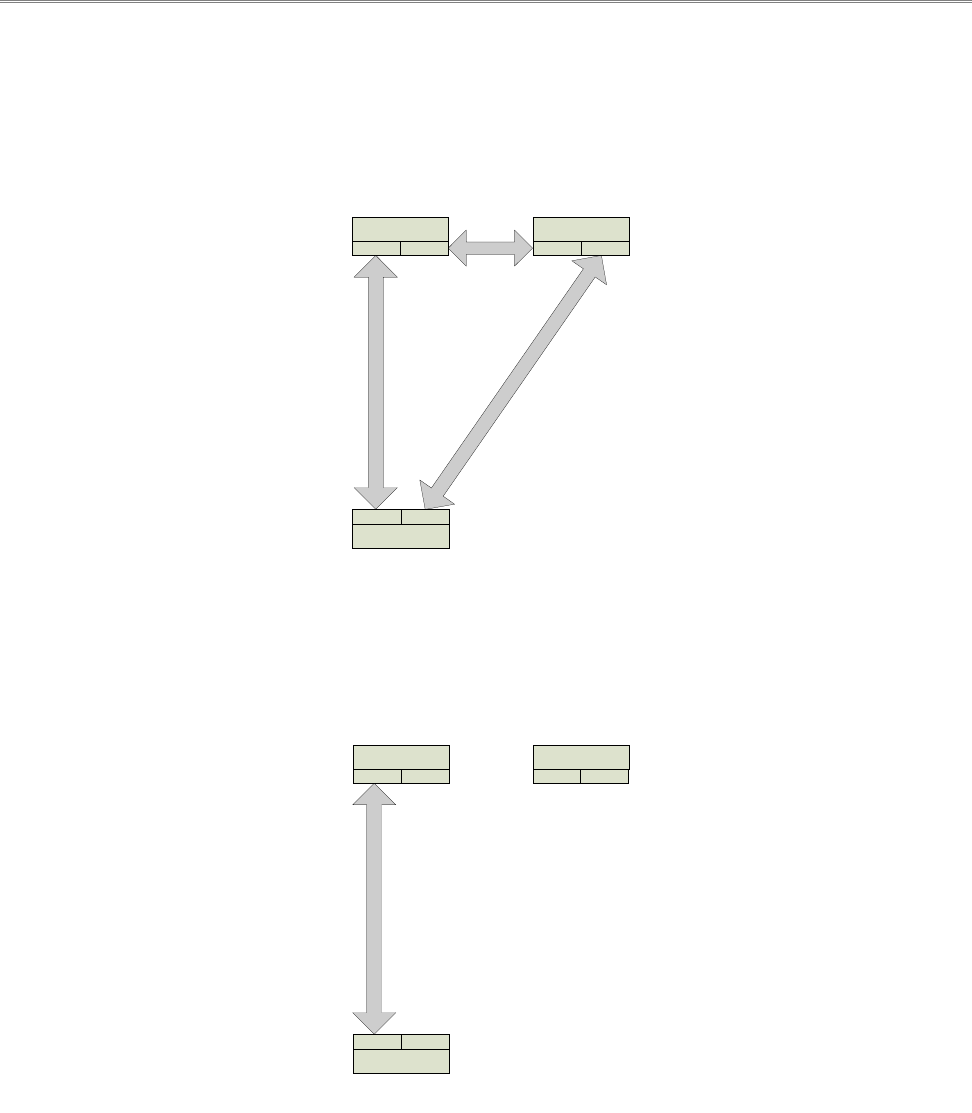
Example 1:
Suppose you have three BreadCrumbs, called A, B, and C. Each has two radios. BreadCrumb A’s
radios are on channels 1 and 8, B’s are on 8 and 11, and C’s are on 1 and 11. All three BreadCrumbs
are using the default ESSID of "breadcrumb54-v10." Assuming that all three BreadCrumbs are
within radio range of one another, the network will be connected, as shown below:
Example 2:
Now suppose that you change the ESSID of BreadCrumb C to "lonely". The network will adjust to
this change, resulting in the following configuration:
Note that BreadCrumb C can no longer communicate with A or B, and vice versa.
1.3 Description of BreadCrumb LX/LX3
The BreadCrumb LX/LX3 is a portable, wireless device deployable in almost any environment. It is
light in weight, and offers up to 3 external antennas, and is designed to be completely mobile as
worn by an individual. The BreadCrumb LX/LX3 must be powered by an external source.
3
Figure 1: All BreadCrumbs use the same ESSID.
3..5(
3..5((
3..59
:3;)
:53:*7
:3;(
:3;(
:53:*7
:3;):3;(
:53:*73
:3;)
Figure 2: ESSID of BreadCrumb C changes to "lonely."
3..5<
:3;=
:53:*7
:3;>
:3;>
:53:*7
:3;=:3;=
:53:*73
:3;>

BreadCrumb® LX/LX3 User Guide Rajant Corporation
Version: 2.94 03-100101-001
(&&( :
BreadCrumb LX offers two radios, while BreadCrumb LX3 offers three radios. 802.11g radios are
used in the 900 MHz and 2.4 GHz bands, and 802.11a radios are used in the 4.9 GHz and 5 GHz
bands. The radios support the following channels and frequencies in the United States and Canada:
.
Not all channels are allowed for use everywhere around the world. Check with the
corresponding wireless spectrum regulatory body to determine the subset of
channels authorized for use in your country.
Table 1: 2.4 GHz Radio Channel and Frequencies.
Channel Number Center Frequency (MHz)
1 2412
2 2417
3 2422
4 2427
5 2432
6 2437
7 2442
8 2447
9 2452
10 2457
11 2462
The default channel for a 2.4 GHz BreadCrumb radio is 11 (2462 MHz).
4

Rajant Corporation BreadCrumb® LX/LX3 User Guide
03-100101-001 Version: 2.94
Table 2: 900 MHz Radio Channel and Frequencies.
Channel Number Center Frequency (MHz)
5 912
6 917
The default channel for a 900 MHz BreadCrumb radio is 6 (917 MHz).
Table 3: 5 GHz Radio Channel and Frequencies.
Band Channel Center Frequency (MHz) Turbo Capability
U-NII Upper Band
(5725 - 5825 MHz
/
ISM Band
(5725 - 5875 MHz
149 5745 No
152 5760 Static Turbo
153 5765 No
157 5785 No
160 5800 Static Turbo
161 5805 No
165 5825 No
The default channel for a 5 GHz BreadCrumb radio is 152 (5760 MHz). Note that this and some
other 5 GHz channels support a feature called Static Turbo mode. In this mode, the radio binds two
standard 20 MHz channels to obtain a wider bandwidth 40 MHz channel. The end result is
improved throughput and/or communication range for the radio.
Most 5 GHz antennas only support a subset of the 802.11a 5 GHz frequency
channels the Rajant radio is capable of operating at. Before changing the channel of
a 5 GHz radio, verify that the channel is supported by the connected antenna.
Since the radios operate at different frequencies, you must be careful to use the
correct type of antenna with each radio. As an example, a 2.4 GHz antenna will not
work with a 5 GHz radio and vice versa.
5

BreadCrumb® LX/LX3 User Guide Rajant Corporation
Version: 2.94 03-100101-001
Table 4: 4.9 GHz Radio Channel and Frequencies.
Channel Number Center Frequency (MHz)
5 4942.5
10 4945.0
15 4947.5
20 4950.0
25 4952.5
30 4955.0
35 4957.5
40 4960.0
45 4962.5
50 4965.0
55 4967.5
60 4970.0
65 4972.5
70 4975.0
75 4977.5
80 4980.0
85 4982.5
90 4985.0
95 4987.5
The default channel for a 4.9 GHz BreadCrumb radio is 40 (4960.0 MHz).
One antenna port per radio is utilized. The antenna ports are accessed through Type N RF
connectors mounted on the LX/LX3 enclosure.
6
Rajant Corporation BreadCrumb® LX/LX3 User Guide
03-100101-001 Version: 2.94
(&&) 5%"
The LX/LX3 enclosure has been designed to operate in extreme conditions. The Ingress Protection
(IP) rating of the enclosure has been tested per IEC 60529. The enclosure has demonstrated
performance compliant to IP67 requirements, providing complete protection against ingress of dust
(6) as well as protection against immersion in water (7).
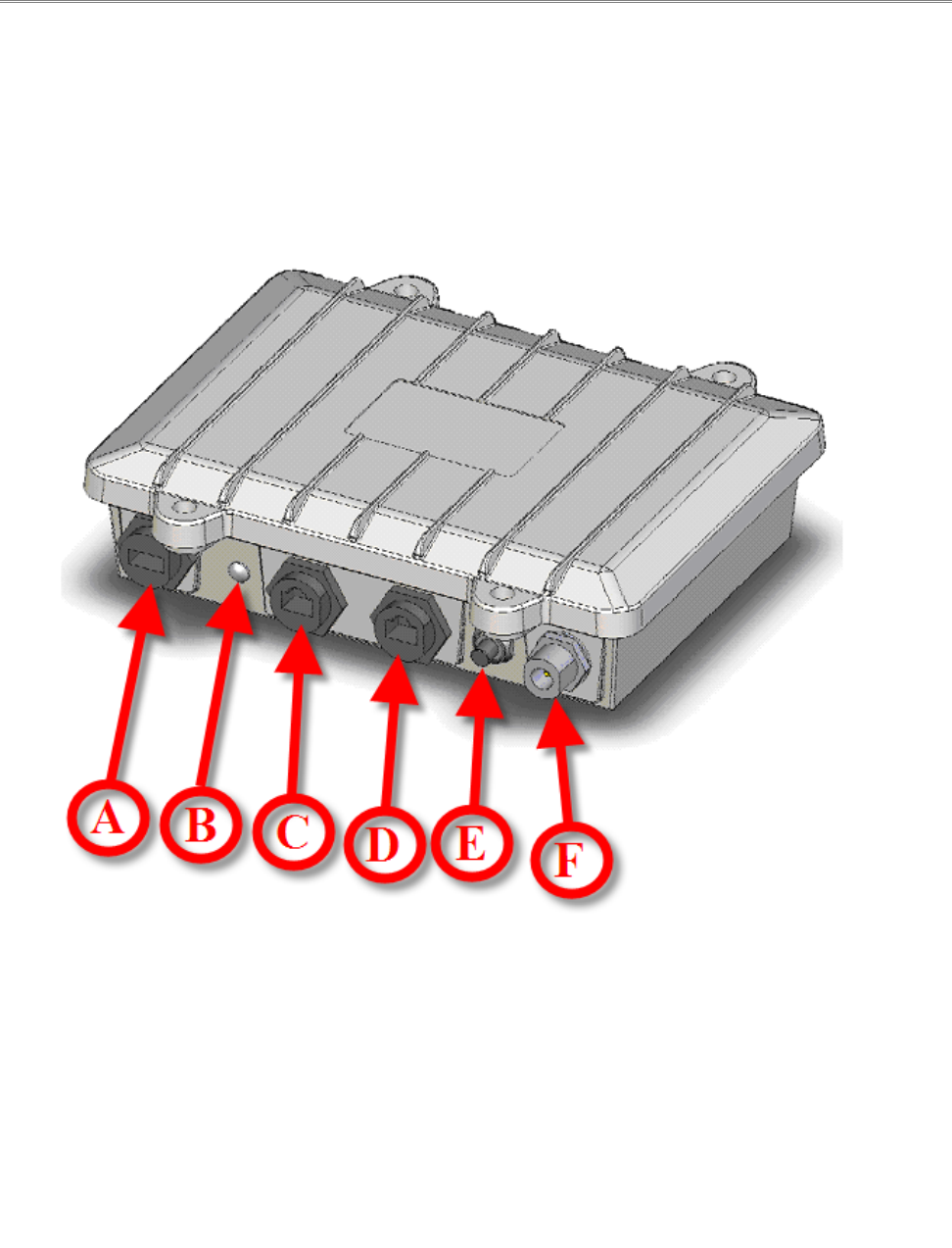
The external features of the enclosure are shown in Figure 3 and Figure 4.
7
A: USB Port. (LX and LX3)
B: Status LED. (LX and LX3)
C: ETH0/PWR RJ45 Port. (LX and LX3)
D: ETH1 RJ45 Port. (LX and LX3)
E: Zeroize Keys and Restore Factory Defaults / LED Configuration Switch (LX and LX3)
F: Type N RF Connector for the 2.4 GHz Antenna. (LX and LX3)
Figure 3: BreadCrumb LX/LX3 Enclosure Features (Top-Front Side).
BreadCrumb® LX/LX3 User Guide Rajant Corporation
Version: 2.94 03-100101-001
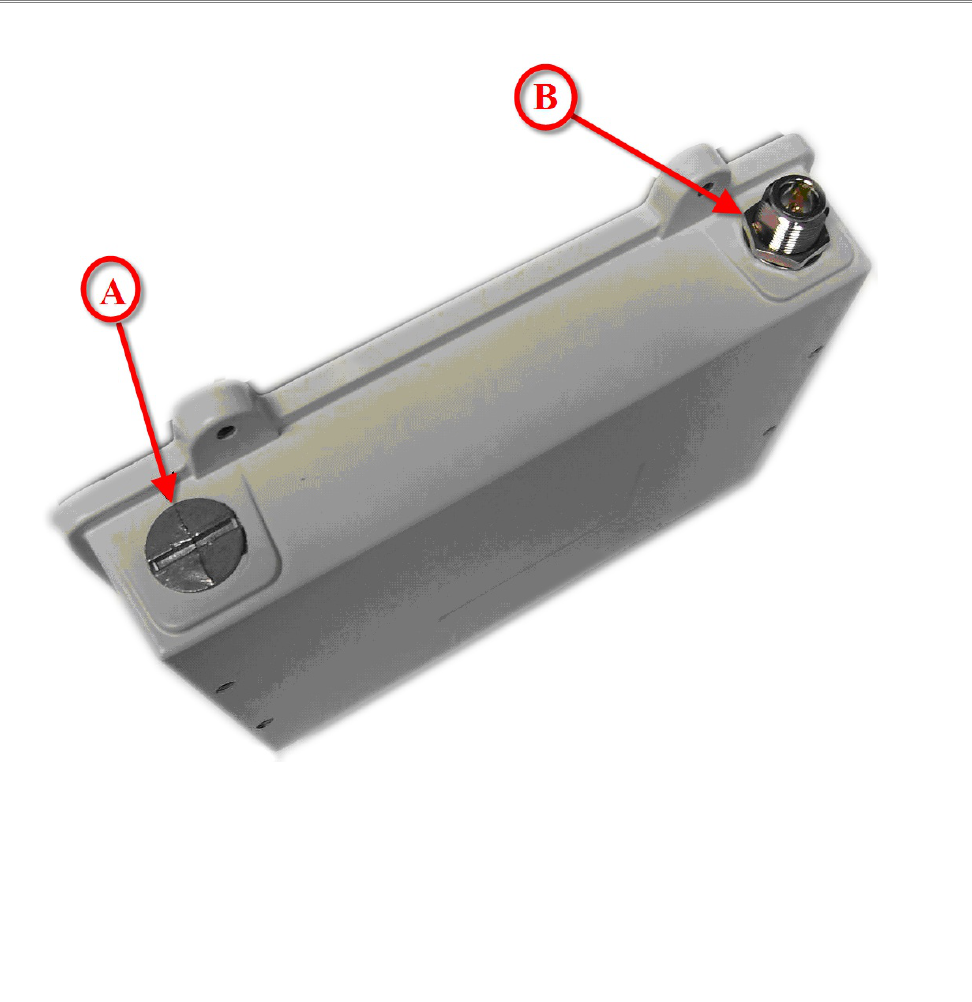
(&& 3%
The BreadCrumb LX provides two Type N female antenna connectors. The connector located on the
front side of the enclosure (see F in Figure 3) interfaces to the 2.4 GHz antenna. The connector
located on the the back side of the enclosure (see B in Figure 4) interfaces to the 900 MHz, 2.4 GHz,
4.9 GHz or 5 GHz antenna depending on the BreadCrumb LX model.
8
A: ½” Closure Plug (Not Utilized). (LX)
Type N RF Connector for the 2.4 GHz, 4.9 GHz or 5 GHz Antenna (Not Shown). (LX3)
B: Type N RF Connector for the 900 MHz, 2.4 GHz, 4.9 GHz or 5 GHz Antenna. (LX)
Type N RF Connector for the 900 MHz or 5GHz Antenna (LX3)
Figure 4: BreadCrumb LX/LX3 Enclosure Features (Bottom-Rear Side).

Rajant Corporation BreadCrumb® LX/LX3 User Guide
03-100101-001 Version: 2.94
Table 5: BreadCrumb LX Radio/Antenna Configurations.
LX Model Front Side Antenna Back Side Antenna
LX-2409 2.4 GHz 900 MHz
LX-2424 2.4 GHz 2.4 GHz
LX-2449 2.4 GHz 4.9 GHz
LX-2450 2.4 GHz 5 GHz
The BreadCrumb LX3 provides three Type N female antenna connectors. The connector located on
the front side of the enclosure (see F in Figure 3) interfaces to the 2.4 GHz antenna. The connector
located on the the back side of the enclosure, on opposite corner of the front side antenna (see B in
Figure 4), interfaces to the 900 MHz or 5 GHz antenna depending on the BreadCrumb LX3 model.
Finally, the remaining connector on the back side of the enclosure (see A in Figure 4) interfaces to
the 2.4 GHz, 4.95 GHz or 5 GHz antenna depending on the BreadCrumb LX3 model.
Table 6: BreadCrumb LX3 Radio/Antenna Configurations.
LX3 Model Front Side Antenna Back Side Antenna 1 Back Side Antenna 2
LX3-2495 2.4 GHz 900 MHz 5 GHz
LX3-2209 2.4 GHz 900 MHz 2.4 GHz
LX3-2250 2.4 GHz 5 GHz 2.4 GHz
LX3-2454 2.4 GHz 5 GHz 4.9 GHz
Because the antennas are mounted top and bottom and on opposite corners of the unit, the only
viable means of using the LX/LX3 with all antennas attached is by using the pole mount option.
Care should be taken to make sure the pole is mounted plumb (or possibly carefully tilted to account
for altitude differences) for reasons noted below:
●The 802.11a 5 GHz Vertically Polarized Omni antenna (OD5WM-6) has an extremely
narrow coverage plane. It only extends 5 degrees above and below the center-line, even at
relatively short range. This means that two units using these antennas will have to be at the
same altitude with the antennas plumb to see each other.
●The 802.11g 2.4 GHz Vertically Polarized Omni antenna (OD24M-7) covers a more lenient
18 degrees above and below center at distance and an even wider range up close. Therefore,
it is much more forgiving of imperfect placement than the 802.11a antenna.
9

BreadCrumb® LX/LX3 User Guide Rajant Corporation
Version: 2.94 03-100101-001
- To avoid possible damage to the BreadCrumb radio(s), always connect or
disconnect external antennas with the power to the BreadCrumb LX/LX3 off.
(&&2 $/5 %
The BreadCrumb LX/LX3 contains two 10/100 Base-TX Ethernet ports named ETH0/PWR RJ45
and ETH1 RJ45 (see Figure 3). Both ports support Auto-MDI/MDIX allowing the use of either
straight-through or crossover data cables for connections to the ports. Use of the supplied data cable
is recommended for outdoor installations. The supplied data cable features a ruggedized RJ45
connector which provides an environmental seal when connected to the ETH0/PWR RJ45 port on
the BreadCrumb LX/LX3.
The ETH0/PWR RJ45 connector also supports Passive Power over Ethernet (Passive PoE), and
therefore acts as a dual function Ethernet and DC power input port for the BreadCrumb LX/LX3.
An external inline injector is used to merge DC power for the BreadCrumb LX/LX3 with data from a
LAN port or a wired client.
To ensure proper operation of the BreadCrumb LX, the inline injector must output a DC voltage
between 18 VDC to 48 VDC @ 20 W minimum (1.1 A @18 VDC). For BreadCrumb LX3, the
inline injector must output a DC voltage between 18 VDC to 48 VDC @ 25 W minimum (1.4 A @18
VDC). Using a higher output voltage facilitates longer cable runs between the inline injector and the
ETH0/PWR RJ45 port on the BreadCrumb LX/LX3.
The BreadCrumb LX/LX3 ships with a standard 48 V AC/DC Passive PoE injector. The Rajant
VHDC-24 is an optional accessory, and supports powering the Breadcrumb LX/LX3 from an
unregulated DC supply.
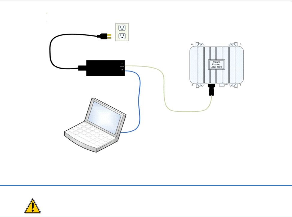
Figure 5 shows the connection of the BreadCrumb LX/LX3 to the AC/DC POE inline injector. The
data/power output of the inline injector is connected to the ETH0/PWR RJ45 port of the
BreadCrumb LX/LX3. To avoid damage to the contacts of the ETH0/PWR RJ45 port, apply power
to the inline injector after connecting the data cable to the ETH0/PWR RJ45 port.
10
Rajant Corporation BreadCrumb® LX/LX3 User Guide
03-100101-001 Version: 2.94
- In order to avoid sparking and possible damage to the unit, be sure to connect the
powered Ethernet cable to the BreadCrumb LX/LX3 before applying power to the
power supply.
(&&, 5
The Status LED is capable of displaying alerts, error codes, and link states. The LED Mode can be
configured in BC|Commander to be ON, OFF, or ALERTS ONLY. When the LED is ON, errors,
warnings, and link status are displayed. When the LED is OFF, errors, warnings, and link states are
not displayed. When the LED is set for ALERTS ONLY mode, the LED will alternate between
displaying the warning or error code and the mesh status.
The Status LED combines the three base colors of red, green and blue to display a broader spectrum
of colors which indicate the current status of a BreadCrumb. The meanings of the color code
indicators are given in Table 7.
11
Figure 5: BreadCrumb LX/LX3 Ethernet and Passive PoE Connections.

BreadCrumb® LX/LX3 User Guide Rajant Corporation
Version: 2.94 03-100101-001
Table 7: Status LED Color Codes.
Color Status
White
(red, green and blue LEDs together;
may appear pale blue or pale green)
Powered, prior to Booting
Solid Red Booting
Blinking Red 1
Error
Solid Blue Ready, but no peers
Solid Green At least one 24 Mbps or higher peer
Blinking Green At least one peer
Blinking Yellow
(at a constant rate) Progress
Blinking Yellow 1
(with short and long pauses between blinks) Warning
All Status LED colors scrolling in succession Success/Completion
(&&? 5#@AB:%#"
/%
The LED Configuration / Zeroize Keys and Restore Factory Defaults Switch (see ) has two modes of
operation. The modes are set by the length of time the switch is asserted. The modes are:
●LED Configuration
●Zeroize Keys and Restore Factory Defaults
1.3.6.1 LED Configuration
This mode is used to control the default and alternate display states of the Status LED. The LED
Configuration function is accessed by pressing the switch and releasing it after a two second hold.
The default display state of the Status LED is dictated by the LED Mode setting that is configured
from BC|Commander (please refer to the BC|Commander User Guide for a more detailed description
of the LED mode setting). The user can toggle between the default state and an alternate state of the
Status LED by pressing the switch and activating the LED Configuration function.
Table 8 illustrates the possible default and alternate display states of the Status LED.
1 For a list of error and warning codes refer to Appendix A at the end of this document.
12

Rajant Corporation BreadCrumb® LX/LX3 User Guide
03-100101-001 Version: 2.94
Table 8: Default and alternate display states of the Status LED.
Default State Alternate State
ON (SWITCHABLE) OFF
ALERTS ONLY (SWITCHABLE) ON
OFF (NON-SWITCHABLE) OFF
OFF (SWITCHABLE) ON
Note that state changes can occur only between options in the same rows of the table above. For
example, it is possible to toggle the state back and forth between ALERTS ONLY and ON, but not
between ALERTS ONLY and OFF. Transitioning from ALERTS ONLY to OFF would require
changing the LED mode setting in BC|Commander.
.
As of firmware release 10.16, there are two different default OFF states: Off
(switchable), which toggles to ON, and Off (non-switchable), which has no alternate
state. If the LED Mode is set to OFF (non-switchable) in BC|Commander, the
Configuration Switch will NOT turn it on.
- The LED remains active until the completion of the boot process. The LED may
display information during the boot process even with the LED mode set to OFF.
The LED must be physically masked (such as adding tape to the LED lens) to
guarantee that no light is emitted at any time.
1.3.6.2 Zeroize Keys and Restore Factory Defaults
This mode is is used to erase the security protocol keys of a BreadCrumb LX/LX3 and to restore its
software configuration to the factory default state. To operate this switch follow these procedures:
●Ensure that the BreadCrumb is powered on, has fully booted-up and its Status LED (see )
color is green or blue (see Table 7).
●Press the switch and hold the switch for approximately 10 seconds until the Status LED
changes to blinking yellow. This indicates that the Zeroize Keys and Restore Factory
Defaults operation has been initiated and is in progress.
●Release the switch. The Status LED should change to display the blinking red error code 32.
See Appendix A for a description of the blinking red color sequence. The BreadCrumb will
then reboot using the factory default configuration.
13

BreadCrumb® LX/LX3 User Guide Rajant Corporation
Version: 2.94 03-100101-001
!
The process of zeroizing keys and restoring factory defaults can also be performed
remotely from within the BC|Commander management software. For details on this
alternative method, refer to the BC|Commander User Guide.
14

Rajant Corporation BreadCrumb® LX/LX3 User Guide
03-100101-001 Version: 2.94
) *+
BC|Commander is Rajant’s software package used for monitoring the status of BreadCrumbs with
version 10 firmware on a BreadCrumb Wireless Network (BCWN). BC|Commander is also used
for configuring version 10 BreadCrumbs and to graphically portray the network topology.
.
BC|Commander includes an option called v10 Transitional Mode. This allows a
user to run a mixture of BreadCrumbs with firmware version 9 and firmware
version 10 within the same mesh network. This is very useful when BreadCrumbs
in a very large network are being upgraded from version 9 to version 10 firmware.
BC|Commander typically runs on a laptop PC, but can be run on any PC that has access to the entire
BCWN. Versions of the software package are available for Microsoft Windows® or Linux.
.
Some portions of the BC|Commander User Guide assume a working knowledge of
TCP/IP networking, including DHCP, NAT and DNS. While the network lay person
may be able to perform some BCWN management tasks, it is recommended that
network configuration be performed by experienced network administrators.
.
The BC|Commander version used must be equal to or greater than the
firmware version running on any administered BreadCrumbs in order to
administer all BreadCrumb firmware features overed in Rajant’s BC|Commander
User Guide.
Rajant periodically releases updated BC|Commander software. The updated software must be
obtained from Rajant. Refer to Rajant’s most recent BC|Commander User Guide for instructions on
how to install the latest version of BC|Commander on your computer and how to use
BC|Commander with Rajant’s BreadCrumbs.
15

Rajant Corporation BreadCrumb® LX/LX3 User Guide
03-100101-001 Version: 2.94
" -"./0
There are many factors which need to be taken into account when deploying the BreadCrumb
Wireless Network (BCWN). Section 3.1 describes the addressing scheme of the BCWN. Section
3.2 discusses channel assignments. Section 3.3 details some of the most commonly occurring
environmental factors that will have a major impact on the performance of the BCWN. Finally,
section 3.4 details guidelines and methodology needed to follow when deploying the BCWN.
3.1 Addressing
When in gateway mode or when using its own embedded DHCP servers, the BreadCrumb Wireless
Network requires that wireless devices use IPv4 addresses in the Class A network 10.0.0.0/8 (that is,
any address that begins with ‘10.’). If you are not connected to another network, or if you are
bridging to one rather than routing to it, your wireless client devices may have any address
whatsoever.
.
Any computers running the BC|Commander management application must have an
address in the same range as the BreadCrumbs they manage. Refer to the
BC|Commander User Guide document for the details of the BreadCrumb IP address
configuration.
&(&( '%3
Each BreadCrumb radio has one IPv4 address in the Class A network 10.0.0.0/8. These addresses are
assigned during manufacturing and cannot be changed in the field. Rajant ensures during
manufacturing that these addresses are not duplicated between any two BreadCrumb devices.
Addresses assigned to BreadCrumb devices can be viewed using BC|Commander.
&(&) $
Each BreadCrumb device includes an embedded DHCP server. You may safely enable the DHCP
servers of multiple BreadCrumb devices simultaneously, and it is in fact the most common case that
all BreadCrumb devices in a BCWN run DHCP servers. Address conflicts among DHCP clients are
prevented by using the unique BreadCrumb device addresses assigned at the factory as a base.
A BreadCrumb device determines its DHCP range as follows:
●Start with the first three bytes of the first radio’s IPv4 address.
●Add a low-byte range of 10 to 210.
3.2 Channel Assignments
BreadCrumb radios have default channels assigned, based on the frequency of the radio. See Table 9
for a list of available radios and their default channel assignments.
17

BreadCrumb® LX/LX3 User Guide Rajant Corporation
Version: 2.94 03-100101-001
Table 9: Default Channel Assignments
Radio Card Frequency Default Channel
900 MHz 6
2.4 GHz 11
4.9 GHz 40
5 GHz 152
In some cases, it may be necessary to manually set the radios to specific channels to provide critical
links within a mesh. This can be especially important when using single-radio BreadCrumb devices.
Refer to the BC|Commander User Guide for the details of BreadCrumb channel configuration.
3.3 Physical Placement and other Considerations
Commonly occurring environmental factors have a significant impact on performance and behavior
of the BreadCrumb Wireless Network. LOS (Line of Sight) obstructions, distance, weather, and
device placement should all be considered when deploying a wireless network.
IEEE 802.11 wireless operation degrades gradually as distance increases between nodes or as
interference becomes prominent. This manifests as a data rate reduction between nodes.
The goal in planning and deploying a BreadCrumb Wireless Network is to maximize both coverage
and the data transfer rate between devices. These can be maximized by taking into consideration all
of the contributing factors described in this section.
&&( 6#6
Unobstructed LOS (Line-of-Sight) is critical for optimal performance of the BCWN. Partial LOS
obstruction results in noticeable network performance degradation. Total LOS obstruction can result
in complete loss of network connectivity.
Elevating the device and external antenna will assist in providing better LOS. This can allow the
radio waves to propagate over some possible obstructions.
Unobstructed LOS is not necessary from every BreadCrumb device and wireless client to every
other BreadCrumb device and wireless client. However, each device must have unobstructed LOS
to the previous and subsequent device.
Client connectivity will degrade and drop if LOS to a BreadCrumb device can not be maintained.
&&) %
Many factors determine acceptable distances between BreadCrumb devices when deploying a
BCWN:
●If many devices are placed too closely together, it is possible that interference will degrade
18

Rajant Corporation BreadCrumb® LX/LX3 User Guide
03-100101-001 Version: 2.94
the performance of the system.
●Devices placed too far away or in RF “shadows” may experience total loss of connection.
●RF transmit power and receive sensitivity are important in determining the distances over
which the device will be effective.
●When placing a BreadCrumb device, check the connection status to the nearest available
device using either the BreadCrumb device’s status LED (described in section 1.3.5 Status
LED), or the
BC|Commander management application. If the connection is poor or non-existent, attempt
to relocate the BreadCrumb device closer to another device until an acceptable connection is
obtained. If a poor connection or no connection is made at even relatively close distances,
you should refer to Chapter 5 Troubleshooting.
●When the connection quality is found to be acceptable from BC|Commander, the distance of
the BreadCrumb device from the network can be increased until an optimal balance between
distance, connectivity and tactical placement is achieved.
&& -
Precipitation and fog also act as obstructions blocking the propagation of the wireless network’s
radio waves.
Light fog or precipitation may result in noticeable degradation of wireless network performance.
Heavy precipitation or fog may result in severe performance degradation and possible loss of
network connectivity.
If the performance of a well functioning network is degraded by worsening weather conditions, it
may be advisable to add BreadCrumb devices into the network to act as short haul repeaters to
counteract the effects of the weather. An alternative is to move the devices closer together.
&&2 #%
RF interference can degrade network performance and can come from many different sources,
including:
●Other BreadCrumb devices that are placed too closely together.
●Other RF devices such as microwave devices, cordless phone base stations, radio
transmitters, other wireless networks, jamming devices, etc.
●Metal surfaces such as fences and building can cause radio waves to be reflected, causing
multipath interference.
Plan the BreadCrumb Wireless Network to minimize the effects of RF interference.
19

BreadCrumb® LX/LX3 User Guide Rajant Corporation
Version: 2.94 03-100101-001
&&, $"%#-.
The placement of BreadCrumb devices has a major impact on maximum effective range, and
therefore network performance. The components must be elevated above the surrounding terrain to
allow for adequate wave propagation. A device placed directly on the ground has a significantly
reduced effective range. Elevating a device above the ground dramatically increased the maximum
effective range. Rajant recommends elevating the components a minimum of 6 ft. above the
surrounding surface.
3.4 Deployment Guidelines and Methodology
This section addresses the actual on-site deployment of the BCWN. While by no means an
exhaustive treatise, it is intended as a good source of guidelines and methodology for the successful
deployment of the BCWN in the field.
&2&( "C"
Follow these guidelines when deploying the BCWN:
1. Placement of BCWN components
(a) Elevate the BCWN components whenever possible.
i. Directly on the ground, the maximum distance between any two BCWN components
is approximately 300 ft. Also, the maximum distance between a wireless client and
the nearest BCWN component is approximately 300 ft.
ii. Rajant recommends elevating each BCWN component a minimum of 6 ft. above the
surrounding terrain for maximum range. Elevating the BCWN components, as little
as 14 inches, has proven to increase the range out to approximately 600 ft.
2. Distance
(a) If you cannot elevate the BCWN components, they can only be approximately 300 ft.
apart. Also, any wireless clients can be no farther than approximately 300 ft. from a
BCWN component.
3. Line of sight
(a) Obstructions to line of sight block/absorb/deflect the wireless network’s radio waves,
resulting in poor network performance or total loss of network connectivity.
(b) When placing the BCWN components, scan the area for LOS obstructions. Envision the
BCWN’s radio waves as a light beam. Look for obstructions that would result in
shadows in the light beam, they will most likely weaken or block the BCWN’s radio
waves.
4. Weather
(a) Light precipitation will reduce the range and performance of the BCWN components and
wireless clients.
(b) Heavy precipitation or fog will most likely result in extremely reduced range and
frequent or total loss of network connectivity.
20

Rajant Corporation BreadCrumb® LX/LX3 User Guide
03-100101-001 Version: 2.94
&2&) "7 "
The steps detailed in this section should assist you in successfully deploying the BCWN.
1. Scan the terrain on which the BCWN will be deployed.
(a) Determine the initial distances between BreadCrumb devices.
Refer to Rajant Troubleshooting Range User Guide for more information.
(b) Note any LOS obstructions, and plan BreadCrumb placement to work around them.
2. Identify the PC on which BC|Commander will be run.
(a) This PC should have a wireless NIC, as you will need to carry it with you as you deploy
the BCWN.
i. Alternatively, the BC|Commander PC can be stationary with one person monitoring
BC|Commander while another deploys the BreadCrumbs. This method requires some
form of communication (radio, cell phone, etc.) between the two persons.
3. Determine the location for the first BreadCrumb.
4. Power ON the device.
5. Wait approximately 90 seconds for the device to boot.
6. Power ON the BC|Commander PC.
7. Start BC|Commander.
8. The BC|Commander console should display the first BreadCrumb.
9. Determine the approximate location for the next BreadCrumb.
10.Proceed to the location for this BreadCrumb, observing the network in BC|Commander as
you progress.
(a) If the BreadCrumb loses network connectivity before you reach its destination, backtrack
until network connectivity is restored. The point at which network connectivity for this
BreadCrumb is restored is most likely the farthest point in this direction at which you will
be able to place this BreadCrumb.
(b) If you reach the destination without losing connectivity you can place it there.
i. At this point, you may choose to proceed farther in an attempt to make optimal use of
the available BreadCrumbs.
ii. If so, proceed until network connectivity is lost and then backtrack until network
connectivity is restored for this BreadCrumb. The point at which network
connectivity is restored for this BreadCrumb is most likely the farthest point in this
direction at which you will be able to place this BreadCrumb.
11.Repeat steps 9 and 10 for any remaining BreadCrumbs.
21

Rajant Corporation BreadCrumb® LX/LX3 User Guide
03-100101-001 Version: 2.94
2 */*
Each BreadCrumb relies on low-level software known as firmware for proper execution. Rajant
periodically releases updated BreadCrumb firmware. The updated firmware must be obtained from
Rajant.
For a BreadCrumb to communicate with other BreadCrumb devices or a BC|Commander client, the
firmware version of the device must be compatible with the firmware versions of all other devices
within the network, and with the version of BC|Commander running on the client computer.
. For procedures to install and upgrade the BC|Commander management application,
refer to the latest BC|Commander User Guide.
To upgrade the firmware on a BreadCrumb through the device's USB port, follow these procedures:
1. Obtain the appropriate firmware file from Rajant for your BreadCrumb model. Save the file
on a computer on which the BC|Commander management application has been installed.
2. Plug a USB storage device into your computer and launch the BC|Commander management
application. Select “File,” then select “USB Flash Manager.” From this point, follow the
instructions that are displayed on your computer screen. When this procedure has been
completed, safely remove the USB storage device from the computer.
3. Turn off power to the BreadCrumb.
4. Connect the USB storage device to the BreadCrumb's USB port.
5. Turn on power to the BreadCrumb.
6. The firmware upgrade process will take several minutes. In the mean time, observe the
Status LED to monitor progress.
(a) When the USB firmware upgrade begins, the Status LED will start blinking yellow,
which identifies progress.
(b) When the process nears completion, the blink rate will increase from once per second to
several times per second.
(c) If the firmware upgrade completes successfully, the Status LED will start rotating
between red, green, blue, cyan, magenta, yellow and white colors.
(d) If an error condition is encountered, the Status LED will start repeating a particular
sequence of long and short blinks in red indicating the error code. If this happens, note
the error code (see Appendix A for an explanation of error codes). Leaving the USB
storage device connected, manually power off and then power on the BreadCrumb. Then
repeat the procedures starting from step 6. This time, the BreadCrumb will go through a
more reliable, failsafe firmware upgrade process, which has a greater chance of
successful completion. If, during the failsafe firmware upgrade process another error
occurs, note the new error code and then apply for technical support.
7. When complete, turn off power and disconnect the USB storage device.
23

BreadCrumb® LX/LX3 User Guide Rajant Corporation
Version: 2.94 03-100101-001
.
An alternative method of upgrading the firmware of a BreadCrumb is explained in
the BC|Commander User Guide. This method, called Over The Air (OTA) firmware
upgrade, offers the convenience of remote and completely software controlled
firmware upgrades.
24

Rajant Corporation BreadCrumb® LX/LX3 User Guide
03-100101-001 Version: 2.94
, !"
5.1 Sporadic Network Connectivity
Table 10: Sporadic Network Connectivity Issues.
Problem Resolution
As a BreadCrumb device’s battery approaches
exhaustion, network connectivity will become
sporadic for the BreadCrumb device and its
associated wireless clients.
Monitory battery usage and charge/replace
batteries as necessary.
Light precipitation or fog beginning after initial
deployment of the BCWN can result in sudden
sporadic network connectivity for BreadCrumb
devices and their associated wireless clients.
Increase the density of the network by adding
more BreadCrumb devices or by moving
existing BreadCrumbs closer together.
As a wireless client moves around through the
coverage area, LOS to the BreadCrumb device
can become obstructed resulting in sporadic
network connectivity for this wireless client.
Train users to maintain LOS to known
BreadCrumb device locations. Place
BreadCrumb devices strategically to ensure
coverage of areas through which users are
expected to move.
A wireless client that moves beyond the range of
the BCWN will experience sporadic, and
eventually complete, loss of network
connectivity.
Drop more BreadCrumb devices as necessary to
increase range.
A wireless client cannot join the network. ●Ensure that BreadCrumb devices are
powered on.
●Ensure that the wireless card in the client
device (laptop) is enabled. This is
usually indicated with a blinking light on
the card.
●Ensure that the wireless card is in
"Infrastructure" or "Access Point" mode,
and not in "Ad Hoc" mode. Scan for the
default ESSID "breadcrumb54-v10" (or
the ESSID that you set for the network)
25

BreadCrumb® LX/LX3 User Guide Rajant Corporation
Version: 2.94 03-100101-001
Problem Resolution
using the software accompanying your
wireless card.
●Ensure that the wireless client’s IP
address settings are configured properly.
●Ensure that the security settings on the
client device and BreadCrumb devices
match.
●Ensure that the client device is not
prevented from connecting by an ACL.
●Ensure that the VLAN settings for the
BreadCrumb allow clients of the ESSID
being used to communicate to the Local
Port of the BreadCrumb. See the VLAN
section of the BC|Commander manual
for more information.
5.2 BreadCrumb Device Cannot Connect to BCWN
Table 11: BreadCrumb to BCWN Connectivity Issues.
Problem Resolution
Discharged batteries can cause the BreadCrumb
device to appear to power up, but not be able to
establish connectivity to the BCWN.
When deploying the BCWN, ensure that the
batteries are fully charged.
When using external antennas, faulty cable
connections or crimped cables can result in
difficulty establishing and maintaining network
connectivity.
Check antenna cables and their connections to
the BreadCrumb device.
26

Rajant Corporation BreadCrumb® LX/LX3 User Guide
03-100101-001 Version: 2.94
5.3 BreadCrumb Power and Start-Up Issues
Table 12: BreadCrumb Power and Start-Up Issues.
Problem Resolution
Discharged external batteries can cause a
BreadCrumb to appear to power up(“PWR”
LED is lit), but fail to start-up.
Monitory battery usage and charge/replace
batteries as necessary.
Electrostatic Discharge can cause a BreadCrumb
to appear to power up (Status LED indicates
power is on with a white light, which can
sometimes appear pale blue or pale green), but
fail to start-up.
Manually reboot the device by turning off or
disconnecting power to the device and turning
power back on.
For BreadCrumbs powered by PoE, in order to
avoid sparking and possible damage to the
device, be sure to connect the powered Ethernet
cable to the BreadCrumb before applying power
to the power supply.
Rapid power cycling can cause a BreadCrumb
JR to appear to power up (“PWR” LED is lit)
but fail to start-up.
Turn off power to the device, wait at least 10
seconds and turn power back on. The
BreadCrumb should start-up normally.
Connecting a cable assembly which has an
active power source (like a battery pack) to a
BreadCrumb JR can cause the power to
fluctuate at startup if it is connected with an
unsteady hand. This can cause the BreadCrumb
to appear to power up (“PWR” LED is lit), but
fail to start-up.
●Disconnect the cable assembly, wait 10
seconds, and try to make the connection
again more smoothly.
●Try connecting the cable assembly to the
BreadCrumb before connecting or
applying power to the power supply.
27

Rajant Corporation BreadCrumb® LX/LX3 User Guide
03-100101-001 Version: 2.94
3435-
All possible BreadCrumb error and warning codes are listed below:
JR/LX/LX3/ME3 Firmware Upgrade Codes (1*).
11 – Flash image file does not exist.
12 – Current flash image version is greater than versions of files found on USB drive.
13 – No flash image files found.
14 – Unable to mount USB drive.
15 – Unlocking of /dev/mtd0 failed.
16 – fconfig for SetFailsafeBoot failed.
17 – Unlocking of /dev/mtd0 failed.
18 – fconfig for SetMainBoot failed.
19 – Copying of zImage failed.
111 – Copying of ramdisk failed.
112 – FIS directory update of ramdisk failed.
113 – Copying of etc failed.
114 – FIS directory update of /etc failed.
115 – Copying failed.
116 – flashunbundle failed.
117 – Version information in flash file name and breadcrumb-buildinfo.conf do not match.
1171 – Platform information in flash file name and breadcrumb-buildinfo.conf do not match.
118 – Untar failed.
119 – FIS directory update of kernel failed.
120 – Failed to mount /etc.
121 – Failed to unmount /etc.
122 – In Failsafe mode, but no USB drive detected.
123 – BreadCrumb will be in failsafe mode and unable to communicate with other BreadCrumbs
after next reboot.
124 – Failed to suspend bcconfigd.
125 – Failed to set boot path to next image.
126 – Failed to erase end of next file system image.
127 – Failed to copy file system image.
A-1

BreadCrumb® LX/LX3 User Guide Rajant Corporation
Version: 2.94 03-100101-001
128 – Failed to checksum file system image.
129 – Failed to create directory for next file system image.
131 – Failed to mount next file system image.
132 – Failed to create directory for settings.
133 – Failed to copy current settings to next file system image.
134 – Failed to unmount next file system image.
141 – Error retrieving flash file.
ME2 Firmware Upgrade Codes (2*)
21 – Flash image file does not exist.
22 – Current flash image version is greater than or equal to versions of files found on the USB
drive.
23 – No flash image files found.
24 – Unable to mount USB drive.
25 – Kernel corrupted.
26 – FS corrupted.
27 – Unmounting of old root file system failed.
28 – Mounting of USB drive failed.
29 – flashunbundle failed.
211 – Version information in flash file name and breadcrumb-build info.conf do not match.
212 – In Failsafe mode, but no USB drive detected.
Self-Test Codes (3*)
31 – Hardware configuration not set. Factory initialization required.
311 – InstaMesh license update required.
32 – BreadCrumb has been zeroized.
321 – BreadCrumb is being zeroized.
33 – Radio not detected. Turn the unit off, and then back on. If the problem persist, contact
technical support.
333 – Low Battery.
34 – Cannot read /dev/nand6 information, or cannot resize or format /dev/nand6.
36 – Hardware monitor missing.
37 – Failed to add ethernet port to bridge.
A-2

Rajant Corporation BreadCrumb® LX/LX3 User Guide
03-100101-001 Version: 2.94
38 – Resetting radio due to error.
FIPS Codes (4*)
41 – FIPS self-tests failed.
411 – OpenSSL FIPS vector test programs not found.
412 – OpenSSL FIPS vector test hash mismatch.
413 – 802.11i AES-CCMP test vectors failed.
414 – Unable to use FIPS CCMP encryption.
415 – Kernel integrity check failed.
416 – Filesystem integrity check failed.
42 – Mixed SecNet/Non-SecNet configuration.
43 – Rekeying error.
44 – Rekeying error.
45 – Rekeying error.
46 – Rekeying error.
47 – Rekeying error.
48 – Rekeying error.
49 – Rekeying error.
431 – Rekeying error.
432 – Rekeying error.
433 – Rekeying error.
434 – Rekeying error.
435 – Rekeying error.
436 – Rekeying error.
441 – Status override CPLD feature not available (wrong CPLD version).
Fatal Codes (5*)
51 – instamesh fatal error.
52 – hostapd fatal error.
53 – cvm fatal error.
54 – madwifi fatal error.
55 – Low memory - automatic reboot scheduled.
A-3

BreadCrumb® LX/LX3 User Guide Rajant Corporation
Version: 2.94 03-100101-001
Battery Gas Gauge Codes (6*)
61 – Battery gas gauge i2c device could not be found.
62 – Incorrect gas gauge revision 1 EEPROM settings.
63 – Incorrect gas gauge revision 2 EEPROM settings.
64 – Incorrect gas gauge revision 3 EEPROM settings.
65 – Unknown gas gauge revision.
66 – Incorrect ME3 gas gauge revision 0 EEPROM settings.
67 – Internal battery charger disabled.
Other Codes (7*)
71 – Host flapping detected.
72 – Critical I2C failure.
A-4

Rajant Corporation BreadCrumb® LX/LX3 User Guide
03-100101-001 Version: 2.94
34*$"7%0
1. Use the supplied four (4) M5 screws to attach the mounting bracket to the LX/LX3.
2. Use the U-Bolts to attach LX/LX3 Pole Top Bracket to a pole.
3. Tighten the four (4) nuts on the two (2) U-Bolts to secure the LX/LX3 assembly to the pole.
B-1
Figure 7: U-Bolts Holding the LX Pole-Top Bracket to a Pole.
Figure 6: LX Pole-Top Bracket with U-Bolts.