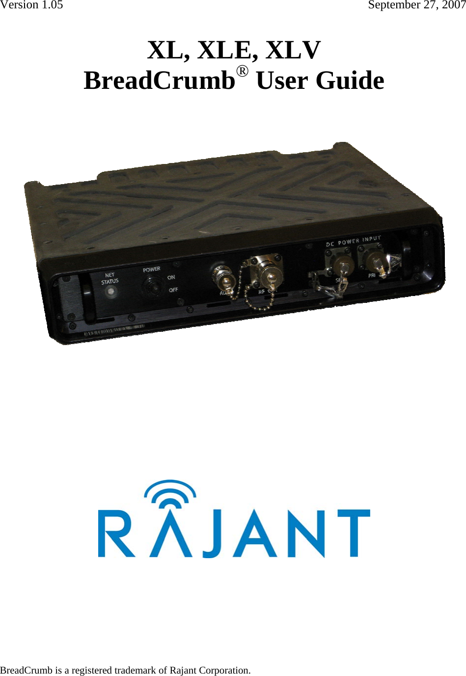
Rajant XLE Long range mobile broadband comunication device User Manual 1 INTRODUCTION

Rajant Corporation Long range mobile broadband comunication device 1 INTRODUCTION

User Manual

Version 1.05         September 27, 2007 XL, XLE, XLV  ®BreadCrumb  User Guide     BreadCrumb is a registered trademark of Rajant Corporation.
Rajant Corporation  XL, XLE, XLV BreadCrumb® User Guide   - 2 - Note:  This device has been tested and found to comply with the limits for a Class A digital device, pursuant to Part 15 of the FCC Rules. These limits are designed to provide reasonable protection against harmful interference when the device is operated in a commercial environment. This device generates, uses, and can radiate radio frequency energy and, if not installed and used in accordance with this instruction manual, may cause harmful interference to radio communications. Operation of this device in a residential area is likely to cause harmful interference in which case the user will be required to correct the interference at their own expense. This Class A digital apparatus complies with Canadian ICES-003. Cet appareil numérique de la classe A est conforme à la norme NMB-003 du Canada. CAUTION: Changes or modifications not expressly approved by Rajant  Corporation could void the user’s authority to operate the device.   Operation of this device in a residential area is likely to cause harmful interference in which case the user will be required to correct the interference at own expense. © 2007 Rajant You may use the software provided with the Products only on personal computers owned by the purchasing individual or entity, and may not use, load, or run any such software on any network or in any type of service bureau, time-sharing operation, or non-purchasing individual or entity's equipment.
XL, XLE, XLV BreadCrumb® User Guide    Rajant Corporation     - 3 - Table of Contents Contents               Page 1.0  PREFACE......................................................................................................................................................... 6 1.1 PURPOSE AND SCOPE ................................................................................................................................6 1.2 USER INFORMATION.................................................................................................................................. 6 2.0 INTRODUCTION............................................................................................................................................. 7 2.1 WHAT IS A BREADCRUMB?...................................................................................................................... 7 2.1.1 TEMPORARY WIRELESS NETWORKS ............................................................................................7 2.1.2 MOBILE WIRELESS NETWORKS......................................................................................................7 2.1.3 WIRELESS NETWORK EXTENSION.................................................................................................7 2.1.4 WIRED NETWORK EXTENSION .......................................................................................................8 2.1.5 ANY COMBINATION OF THE ABOVE.............................................................................................8 2.2 MOBILITY THROUGH MESHING.............................................................................................................. 8 2.2.1 MESH – A DEFINITION.......................................................................................................................8 2.2.2 BREADCRUMB DEVICES MESH BY CHANNEL AND ESSID.......................................................8 2.3 DESCRIPTION OF XL, XLE & XLV BREADCRUMBS ........................................................................... 10 2.3.1 FEATURES ..........................................................................................................................................10 2.3.2 FRONT PANEL FEATURES...............................................................................................................11 2.3.3 REAR PANEL FEATURES.................................................................................................................11 2.4  NETWORK FEATURES............................................................................................................................. 12 2.5  POWER FEATURES................................................................................................................................... 12 2.6  CABLE CONNECTOR PIN INFORMATION............................................................................................ 12 2.6.1  2-PIN POWER CONNECTOR............................................................................................................12 32-PIN CONNECTOR ..................................................................................................................................13 3.0  USING BCADMIN™...................................................................................................................................... 15 3.1 SCREEN LAYOUT...................................................................................................................................... 16 3.1.1 TOPOLOGY AREA.............................................................................................................................17 3.1.2 ANATOMY OF THE BREADCRUMB BOX.....................................................................................18 3.2 ANATOMY OF A CONNECTION LINE.................................................................................................... 19 3.2.1 ASYMMETRIC CONNECTIONS.......................................................................................................20 3.2.2 INFO AREA .........................................................................................................................................21 3.3 CONFIGURING INDIVIDUAL BREADCRUMBS.................................................................................... 22 3.3.1 GENERAL SETTINGS........................................................................................................................22 3.4 RADIO SETTINGS...................................................................................................................................... 24 3.5 REACHBACK SETTINGS .......................................................................................................................... 25 3.6 FORWARDING SETTINGS........................................................................................................................ 27 3.6.1 EXT. PORTS ........................................................................................................................................28 3.6.2 PROTOCOL .........................................................................................................................................28 3.6.3 IP ADDRESS........................................................................................................................................28 3.6.4 TO PORTS............................................................................................................................................28 3.7 SECURITY................................................................................................................................................... 28 3.7.1 WEP......................................................................................................................................................29 3.7.2 ACCESS CONTROL LISTS (ACLs)...................................................................................................29 3.7.4 ENCRYPTING WIRED TRAFFIC......................................................................................................31 3.7.5 ZEROIZING THE ACCESS ID/FACTORY RESET...........................................................................32 3.7.6 AES-256 ENCRYPTION WITH OPENSSL........................................................................................32 3.7.7 ENABLING/DISABLING OpenSSL AES-256 ENCRYPTION .........................................................33 3.7.8 ENCRYPTING WIRED TRAFFIC......................................................................................................33 3.7.9 ZEROIZING THE KEY .......................................................................................................................33 3.7.10 HARRIS SecNET11 ...........................................................................................................................34 3.8 BCADMIN PREFERENCES........................................................................................................................ 34 3.8.1 BREADCRUMB INACTIVITY THRESHOLD (SECONDS) ............................................................34 3.8.2 GPS STALENESS WARNING THRESHOLD (MINUTES)..............................................................35 3.8.3 DEFAULT BATTERY WARNING THRESHOLD (MINUTES).......................................................35
Rajant Corporation  XL, XLE, XLV BreadCrumb User Guide - 4 - 3.9 MAPPING WITH FUGAWI TRACKER ..................................................................................................... 35 4.0  DEPLOYING THE BREADCRUMB WIRELESS LAN ........................................................................... 36 4.1 OVERVIEW OF BCWL DEPLOYMENT ................................................................................................... 36 4.2 DEPLOYMENT CONSIDERATIONS ........................................................................................................ 36 4.2.1 ADDRESSING.....................................................................................................................................36 4.2.1.1 BREADCRUMB DEVICE ADDRESSES ........................................................................................36 4.2.1.2 DHCP.................................................................................................................................................36 4.3 CHANNEL ASSIGNMENTS....................................................................................................................... 37 4.4 PHYSICAL PLACEMENT AND OTHER CONSIDERATIONS................................................................ 37 4.4.1 LINE OF SIGHT...................................................................................................................................37 4.4.2 DISTANCE...........................................................................................................................................37 4.4.3 WEATHER...........................................................................................................................................38 4.4.4 INTERFERENCE.................................................................................................................................38 4.4.5 PLACEMENT OF BCWL COMPONENTS........................................................................................38 4.5 DEPLOYMENT CONFIGURATIONS........................................................................................................ 38 4.5.1 DEPLOYMENT CONFIGURATION – COVERAGE AREA ............................................................39 4.5.2 DEPLOYMENT CONFIGURATION – REACH AREA.....................................................................39 4.6 DEPLOYMENT GUIDELINES AND METHODOLOGY.......................................................................... 40 4.6.1 DEPLOYMENT GUIDELINES...........................................................................................................40 4.6.2 DEPLOYMENT METHODOLOGY....................................................................................................41 4.6.3 BITE LED.............................................................................................................................................44 5.0  BREADCRUMB SOFTWARE MAINTENANCE...................................................................................... 45 5.1 BREADCRUMB FIRMWARE .................................................................................................................... 45 5.1.1 INTRODUCTION ................................................................................................................................45 5.1.2 UPGRADING THE FIRMWARE........................................................................................................45 5.1.3 FLASH UPDATE PROCEDURE FOR VERSION 3 SYSTEMS........................................................45 5.1.4 UPGRADING THE FIRMWARE........................................................................................................46 5.2 BCADMIN MAINTENANCE...................................................................................................................... 46 5.2.1 UPGRADING OR INSTALLING THE BCADMIN SOFTWARE.....................................................46 5.3 PORT FORWARDING ................................................................................................................................51 5.3.1 SETTINGS............................................................................................................................................51 6.0 TROUBLESHOOTING.................................................................................................................................. 52 6.1 BREADCRUMB WIRELESS NETWORK.................................................................................................. 52 6.1.1 SPORADIC NETWORK CONNECTIVITY .......................................................................................52 6.1.2 BREADCRUMB DEVICE CANNOT CONNECT TO BCWN...........................................................53
XL, XLE, XLV BreadCrumb® User Guide    Rajant Corporation     - 5 - List of Figures Figure                    Page  FIGURE 1. XL, XLE, XLV FRONT PANEL..............................................................................................................11 FIGURE 2. XL, XLE, XLV REAR PANEL ...............................................................................................................11 FIGURE 3. 2-PIN POWER CONNECTOR ...................................................................................................................12 FIGURE 4. 32-PIN CONNECTOR..............................................................................................................................13 FIGURE 5. BCADMIN INITIAL SCREEN AT STARTUP ..............................................................................................16 FIGURE 6. BCADMIN SCREEN AT STARTUP (NO NETWORK ADDRESS IN THE 10.0.0.0/8 RANGE).........................17 FIGURE 7. BREADCRUMB REPRESENTED ON BCADMIN TOPOLOGY AREA ............................................................18 FIGURE 8. CLIENT DEVICE'S MAC ADDRESS ........................................................................................................19 FIGURE 9. ASSYMETRIC LINKS ..............................................................................................................................21 FIGURE 10. BREADCRUMB SUMMARY PANEL .......................................................................................................21 FIGURE 11. EXAMPLE LISTING OF BREADCRUMB CONNECTIONS..........................................................................22 FIGURE 12. BREADCRUMB PROPERTIES – GENERAL TAB......................................................................................23 FIGURE 13. BREADCRUMB PROPERTIES – RADIOS TAB.........................................................................................24 FIGURE 14. BREADCRUMB PROPERTIES – REACHBACK TAB.................................................................................25 FIGURE 15. BREADCRUMB PROPERTIES – FORWARDING TAB...............................................................................27 FIGURE 16. WEP CONFIGURATION SCREEN ..........................................................................................................29 FIGURE 17. ACCESS CONTROL SETTINGS WINDOW...............................................................................................30 FIGURE 18. SET ACCESS ID WINDOW ...................................................................................................................31 FIGURE 19. CHANGE ACCESS ID/KEY WINDOW....................................................................................................33 FIGURE 20. BC ADMIN PREFERENCES WINDOW....................................................................................................34 FIGURE 21. DEPLOYMENT CONFIGURATION - COVERAGE AREA ...........................................................................39 FIGURE 22. DEPLOYMENT CONFIGURATION - REACH AREA..................................................................................40 FIGURE 23. BCADMIN SOFTWARE INSTALLATION FILE ........................................................................................46 FIGURE 24. INSTALLATION SCREEN #1 – WELCOME TO BCADMIN SETUP WIZARD..............................................47 FIGURE 25. BCADMIN INSTALLATION SCREEN #1 – WELCOME TO BCADMIN SETUP WIZARD ............................48 FIGURE 26. BCADMIN INSTALLATION SCREEN #2 – SELECT DESTINATION DIRECTORY.......................................48 FIGURE 27. BCADMIN INSTALLATION SCREEN #3 – SELECT START MENU FOLDER .............................................49 FIGURE 28. BCADMIN INSTALLATION SCREEN #4 – SELECT DESTINATION DIRECTORY.......................................49 FIGURE 29. BCADMIN INSTALLATION SCREEN #5 – SELECT ADDITIONAL TASKS ................................................50 FIGURE 30. BCADMIN INSTALLATION SCREEN #6 – COMPLETING THE BCADMIN SETUP WIZARD ......................50
Rajant Corporation  XL, XLE, XLV BreadCrumb User Guide - 6 - 1.0  PREFACE 1.1 PURPOSE AND SCOPE  This manual provides information and guidance to all personnel who are involved with and use Rajant Corporation’s BreadCrumb® Wireless Network devices ("BreadCrumb® devices").  This manual begins with an introduction to the BreadCrumb Wireless Network and a brief overview of the various BreadCrumb device models available. This is followed by a guide to BCAdmin™, the management application used to configure BreadCrumb devices before or during a deployment. Finally, common deployment scenarios are described and concise step-by-step instructions for each scenario are provided.  1.2 USER INFORMATION  The user of this manual is encouraged to submit comments and recommended changes to improve this manual. Please send any comments or changes to www.support@rajant.com . Be sure to include the version number of the manual you are using and please provide the page numbers related to your comments wherever possible.
XL, XLE, XLV BreadCrumb® User Guide    Rajant Corporation 2.0 INTRODUCTION Rajant Corporation's (www.rajant.com) XL, XLE, XLV BreadCrumb integrates Ethernet and wireless IEEE 802.11b/g connectivity with mesh networking protocols.  The network is mobile, self-integrating, self-meshing, self-healing, full-duplex and secure.  An internal Li Ion rechargeable standby battery can power the unit when external power is unavailable.  The focus is on flexibility, adaptability, and simplicity. The BC (BreadCrumb) is intended for rapid deployment of a broadband wireless network into a situation or ‘hot zone’. The BreadCrumb wireless network components utilize the IEEE 802.11b/g wireless networking standard to form a wireless mesh network.  The network can be deployed as a stand-alone wireless network, or bridged to another network (such as the Internet) utilizing available reachback communication links (such as a DSL, cable, or satellite modem). NOTE: This equipment has been tested and found to comply with the limits for a Class A digital device, pursuant to Part 15 of the FCC Rules. These limits are designed to provide reasonable protection against harmful interference when the equipment is operated in a commercial environment.  This equipment generates, uses, and can radiate radio frequency energy and, if not installed and used in accordance with the instruction manual, may cause harmful interference to radio communications. Operation of this equipment in a residential area is likely to cause harmful interference in which case the user will be required to correct the interference at his own expense.   2.1 WHAT IS A BREADCRUMB?  A Bread Crumb device is an 802.11b (Wi-Fi) Access Point specifically designed for the following scenarios:  2.1.1 TEMPORARY WIRELESS NETWORKS  Networks that must be established quickly and with minimal effort for short-term use.  (e.g., a network established to provide First Responder support at the site of a disaster). 2.1.2 MOBILE WIRELESS NETWORKS  Networks in which the network infrastructure itself is mobile, in addition to client devices (e.g., a convoy viewing a video stream from a UAV). 2.1.3 WIRELESS NETWORK EXTENSION  Networks in which a wireless network must be quickly extended around or through obstacles that block wireless communications (e.g., urban canyon networks, tunnels/caves, etc.).       - 7 -
Rajant Corporation  XL, XLE, XLV BreadCrumb User Guide - 8 - 2.1.4 WIRED NETWORK EXTENSION  Networks in which two or more wired LANs at different locations must be connected wirelessly (e.g., to securely connect combat service support computers with logistics bases). 2.1.5 ANY COMBINATION OF THE ABOVE Most BreadCrumb deployments include elements from more than one of the above scenarios.  In many cases, BreadCrumb devices will perform all of the above tasks as shipped with no configuration necessary at all, providing an instant TAN -a Tactical Area Network. Moreover, because BreadCrumb devices use industry-standard 802.11b communications, client devices such as laptops or handheld computers require no special hardware, software, or configuration to access a BreadCrumb Wireless Network.  2.2 MOBILITY THROUGH MESHING  The key component to a BreadCrumb Wireless Network is a technique known as Meshing. While this is generally handled automatically by BreadCrumb devices, complex deployment scenarios require a basic understanding of how BreadCrumb devices establish and maintain a mesh.  2.2.1 MESH – A DEFINITION  A mesh is a collection of network devices (in our case, BreadCrumb devices), each of which is connected to one or more other BreadCrumb devices. Data can move between BreadCrumb devices via these links, possibly passing through several intermediate BreadCrumb devices before arriving at its final destination.  The intelligence of a BreadCrumb Wireless Network is in how it adapts rapidly to the creation or destruction of the links in the mesh as devices are moved, switched OFF or ON, blocked by obstructions, interfered with by other devices, or otherwise affected. This adaptation takes place automatically and immediately as needed.  Note: Although all BreadCrumb devices can be Access Points, most Access Points do not provide any meshing capabilities. Traditional Access Points simply allow wireless devices within range to connect to a wired network; they do not extend range through other Access Points.  2.2.2 BREADCRUMB DEVICES MESH BY CHANNEL AND ESSID  Two BreadCrumb devices establish a mesh link to one another when they share both a radio channel and an ESSID. The 802.11b radios used by BreadCrumb devices support 11 different channels for communication, numbered 1-11. By default, each BreadCrumb device radio is on channel 1, or 11. Most BreadCrumb devices have two radios, using two of those channels.  An ESSID is essentially a name for a wireless network. By default, BreadCrumb devices use the ESSID "breadcrumb".
XL, XLE, XLV BreadCrumb® User Guide    Rajant Corporation     - 9 - Example 1  Suppose you have three BreadCrumb devices, called A, B, and C. Each has two radios. BreadCrumb device A’s radios are on channels1 and 8, B’s are on 8 and 11, and C’s are on 1 and 11. All three BreadCrumb devices are using the default ESSID of "breadcrumb". Assuming that all three BreadCrumb devices are within radio range of one another, the network will be connected, Example 2  Now suppose that you change the ESSID of BreadCrumb device C to "lonely". The network will adjust to this change. Note that BreadCrumb device C can no longer communicate with A or B, and vice versa.  Table  1. Comparison of XL, XLE and XLV BreadCrumbs   BreadCrumb®XL BreadCrumb®XLE BreadCrumb®XLV Dimensions  12" x 12" x 2.5"  12" x 12" x 2.5"  12" x 12" x 2.5"     Weight  13.6 lbs   14.4 lbs   14.2 lbs  Input Power  9—15 VDC   6—15 VDC   9—40 VDC  Power Consumption  12.2 W @ 12 V   Reg: 22.7 W @ 12 V Veh: 31.1 W @ 24 V   Reg: 12.2 W @ 12 V Veh: 15.2 W @ 24 V  Operating Temperature  –20°—60°C   –20°—60°C   –20°—60°C  Standard Battery  N/A - Vehicle Battery Cable   N/A -Vehicle Power Cable   N/A -Vehicle Power  Cable  Number of Radios  2   2   2  Ethernet  Yes   Yes   Yes  RF Output Power  26 dBm / Channel ±2 dBm  26 dBm / Channel ±2 dBm   26 dBm / Channel ±2 dBm  Receive Sensitivity  11 Mbps: -85 dBm 1 Mbps: –92 dBm @PER <8%   11 Mbps: -89 dBm 5.5 Mbps:  –91 dBm 2 Mbps: -93 dBm   1 Mbps: –94 dBm @PER <8%  11 Mbps: -85 dBm 1 Mbps: –92 dBm @PER <8%  Security  Access Control Lists; WEP; Third party VPNs; Type 1 encryption with Harris SecNet 11  Access Control Lists; WEP; Third party VPNs; Type 1 encryption with Harris SecNet 11  Access Control Lists; WEP; Third party VPNs; Type 1 encryption with Harris SecNet 11  Integrated Antenna  None   None   None  External Antenna Connectors  1x female N-type  (radios combined internally)  1x female N-type  (radios combined internally)  1x female N-type  (radios combined internally) Managed Networking Features  Bridging, Gateway, DHCP, NAT, Port Forwarding   Bridging, Gateway, DHCP, NAT, Port Forwarding   Bridging, Gateway, DHCP, NAT, Port Forwarding
Rajant Corporation  XL, XLE, XLV BreadCrumb User Guide - 10 - 2.3 DESCRIPTION OF XL, XLE & XLV BREADCRUMBS 2.3.1 FEATURES The BreadCrumb XL is a long-range model, capable of 11 Mbits/s communications at distances of 7 miles (11.2 km) or more, and lower-speed communications at even greater range. As examples, BreadCrumb XLs have been rapidly deployed: In Air Traffic Control towers  On mountain tops  On ships  NOTE:  The range-extending circuitry within a BreadCrumb XL is permanently tuned to 802.11b channels 1 and 11. Changing these settings may prevent your network from operating properly. The BreadCrumb XLV is identical to the BreadCrumb XL, with the exception that it also accepts unfiltered vehicle power (6—40 VDC) as a power source. This allows long-range communication within and among vehicle convoys and bases, and enables the bridging of widely spread networks by vehicles. As examples, BreadCrumb XLVs have been rapidly deployed: In HMMWVs  In Bradley Fighting Vehicles  In trucks  The BreadCrumb XLE is identical to the BreadCrumb XLV, except that it also includes an MPEG video encoder and an external BNC video connector. A composite video source can be connected to the BreadCrumb XLE and its video stream will be available to other devices on the BCWN. As examples, BreadCrumb XLEs have been rapidly deployed to provide video from:  Security cameras  LRASSS (Long-Range Advanced Scout Surveillance System)
XL, XLE, XLV BreadCrumb® User Guide    Rajant Corporation 2.3.2 FRONT PANEL FEATURES  Figure 1. XL, XLE, XLV Front Panel A. Status LED Built In test and evaluation indicator (BITE) - status light B. Power Switch  C. Composite Video Input (BNC) (only available on the XLE model) D. Antenna Connector (N-Type) E. Secondary DC Input Power 12 VDC F. Primary DC Input Power 12 VDC 2.3.3 REAR PANEL FEATURES  Figure 2. XL, XLE, XLV Rear Panel  A. External Ethernet B. 6—40 VDC Rear Power Connector       - 11 -
Rajant Corporation  XL, XLE, XLV BreadCrumb User Guide 2.4  NETWORK FEATURES Each BreadCrumb XL, XLE, XLV device has one IEEE 802.11b/g wireless NICs (network interface cards), one externally accessible Ethernet port. The wireless NIC, enables the BCWL components to communicate and form the wireless LAN, as well provide access for wireless clients to connect and communicate.  The Ethernet ports provide hardwired connections to auxiliary network devices and clients.  The Ethernet ports also provide a secure connection for some device configuration options which are not available through wireless connections.  2.5  POWER FEATURES Each BreadCrumb XL, XLE, XLV is shipped with a 12 V AC/DC power supply. The BreadCrumb XL, XLE, XLV may, however be powered by any regulated DC power source that is 6—18 V DC, 2.5 A. Primary power is provided though the 2-pin power connector  2.6  CABLE CONNECTOR PIN INFORMATION 2.6.1  2-PIN POWER CONNECTOR  Figure 3. 2-Pin Power Connector  Table  2. 2-Pin Power Connection Pin Letter  Pin Name  Pin DescriptionA 12 VDC Power B GND Ground          - 12 -
XL, XLE, XLV BreadCrumb® User Guide    Rajant Corporation 32-PIN CONNECTOR   Figure 4. 32-Pin Connector     - 13 -
Rajant Corporation    XL, XLE, XLV BreadCrumb User Guide - 14 - Table  3. 32-Pin Connector Pin Letter  Pin Name  Pin Description A  GND  12 VDC REGULATED IN –  B  GND  12 VDC REGULATED IN –  C Reserved  — D Reserved  — E Reserved  — F Reserved  — G  GND  6—40 VDC UNREGULATED IN –  H  GND  6—40 VDC UNREGULATED IN –  J Reserved  — K  VDC_IN_+V  6—40 VDC UNREGULATED IN + (Vehicle Power) NOT functional on XL model L  VDC_IN_+V  6—40 VDC UNREGULATED IN + (Vehicle Power) NOT functional on XL model M Reserved  — N Reserved  — P Reserved  — R  VDC_IN_+V  12 VDC REGULATED IN + S  VDC_IN_+V  12 VDC REGULATED IN + T Reserved  — U Reserved  — V Reserved  — W Reserved  — X Reserved  — Y Reserved  — Z Reserved  — a Reserved  — b Reserved  — c Reserved  — d Reserved  — e Reserved  — f Reserved  — g  VDC_IN_+V  12 VDC REGULATED OUT + h  GND  12 VDC REGULATED OUT – j Reserved  —
XL, XLE, XLV BreadCrumb User Guide  Rajant Corporation - 15 - 3.0  USING BCADMIN™Note:  Some portions of this section assume a working knowledge of TCP/IP networking, including DHCP, NAT, and DNS. While the network lay person may be able to perform some BCWN management tasks, it is recommended that network configuration be performed by experienced network administrators.  BCAdmin is an application allowing an administrator to perform several tasks on a BreadCrumb Wireless Network, including:  • Monitor its status  • Configure network-wide settings  • Configure individual BreadCrumb devices  • Graphically view the BCWN topology in real time   BCAdmin typically runs on a laptop PC, but it can be run on any PC that has access to the entire BCWN. Versions are available for Microsoft Windows® or Linux.  Note:  BCAdmin version 9.64 or higher is required to administer all firmware features that are covered in this manual.
Rajant Corporation    XL, XLE, XLV BreadCrumb® User Guide 3.1 SCREEN LAYOUT When BCAdmin is launched the screen will initially look like this: The large area on the left is the Topology Area, showing the current shape of the network at any given time. The Info Area to the right shows detailed information for BreadCrumb devices, client devices, and wireless links.   Figure 5. BCAdmin Initial Screen at Startup Note:  If your BCAdmin workstation does not have a network address in the 10.0.0.0/8 range,   the large black area will instead be red, as in Figure 5, until you obtain such an address. A red Topology Area indicates that no communication with BreadCrumb devices is possible (this could be caused by no BreadCrumb devices being turned on, or the workstation has not associated with any BreadCrumbs).  - 16 -
XL, XLE, XLV BreadCrumb® User Guide                Rajant Corporation  Figure 6. BCAdmin Screen at Startup (No Network Address in the 10.0.0.0/8 Range) When BCAdmin is able to communicate to a BCWN, the network topology is shown in the Topology Area, as below (your network will look different).  3.1.1 TOPOLOGY AREA The Topology Area shows the topology (logical shape) of your network as it changes. BreadCrumb devices and client devices (laptops, etc.) are shown graphically, as well as the links between them.  Important: The Topology Area shows the logical layout of your network, not the physical layout. While there may be some correlation between the picture you see and the physical locations of your BreadCrumb devices and client devices, physical locations are not represented in this diagram.  Tip: BCAdmin makes an effort to layout the Topology Area in an easily readable way, with a minimum of line intersections and superimposed boxes. Sometimes, however, the screen can get cluttered. BCAdmin provides two features to help cope with this, which may be used in combination:  • A Play/Pause button in the toolbar below the File menu allows you to enable/disable continuous layout, effectively allowing you to ‘lock’ BreadCrumb devices in place.  • BreadCrumb device and client device icons can be dragged to desired positions in the Topology Area using the mouse.  The larger blocks in the Topology Area represent BreadCrumb devices. The smaller blocks with blue outlines represent client devices.   - 17 -
Rajant Corporation    XL, XLE, XLV BreadCrumb® User Guide Detailed information for a BreadCrumb device can be viewed in the Info Area by selecting the BreadCrumb device in the Topology Area. A BreadCrumb device can be selected by single-clicking it with your mouse. The selected BreadCrumb device will be highlighted with a dashed border. A description of the detailed information is provided later in this chapter. 3.1.2 ANATOMY OF THE BREADCRUMB BOX  The following figure shows a close-up image of a BreadCrumb device as represented on the BCAdmin Topology Area.  Figure 7. BreadCrumb represented on BCAdmin Topology Area 3.1.2.1. BREADCRUMB DEVICE NAME The BreadCrumb device’s name is displayed in the upper-left area of the BreadCrumb Box. The name is assigned by an administrator using the process described in the Section called Configuring Individual BreadCrumbs. This allows the administrator to distinguish between multiple  BreadCrumb devices in a BCWN.  If the BreadCrumb device has no name assigned, its ID is used. The ID is a unique, alphanumeric, non-editable string used internally by the BreadCrumb device.  3.1.2.2. TIME SINCE LAST UPDATE  Each BreadCrumb device sends periodic information updates to BCAdmin, in intervals ranging from about 5 seconds to about 20 seconds. This number shows how long it has been, in seconds, since BCAdmin last heard from this BreadCrumb device.  By default, BCAdmin will color the BreadCrumb Box red and make a sound if a BreadCrumb device has not sent an update for 60 seconds. This may simply be because a BreadCrumb device has been switched off, or its battery has died, or it may indicate a problem with the network, its deployment, the local radio environment, or other factors.  3.1.2.3. NUMBER OF PEERS  A peer is simply another BreadCrumb device to which a BreadCrumb device has meshed. Data packets are automatically routed through peers as necessary by the BreadCrumb devices.  3.1.2.4. NUMBER OF CLIENTS A client is any IEEE 802.11b device that has associated with a BreadCrumb device’s access point. Laptops, handheld computers, cameras, VOIP + Wi-Fi phones, etc. are examples of client devices.  - 18 -
XL, XLE, XLV BreadCrumb® User Guide                Rajant Corporation Tip:  The amount of information displayed for each BreadCrumb device can be changed by right-clicking on a BreadCrumb device and choosing Show More Detail or Show Less Detail. The detail level for the entire network can be changed via the View Menu at the top of the window. The above figure shows BCAdmin’s the default level of detail.  3.1.3 ANATOMY OF THE CLIENT BOX  Client devices are represented in the Topology Area by a blue box containing the client device’s MAC address, as pictured below.   Figure 8. Client Device's MAC Address 3.1.3.1. CLIENT MAC ADDRESS/NICKNAME  The MAC address or administrator-set nickname of the client device. Tip:  An administrator can set nicknames for each client device. These nicknames are then displayed in the Topology Area instead of the MAC address. To set a nickname, right-click on the client device and choose Set Client Nickname. 3.2 ANATOMY OF A CONNECTION LINE  If your BCWN has more than one BreadCrumb device, your Topology Area probably includes several lines connecting BreadCrumb boxes to clients and to one another. The color, style, and direction of motion (if any) of a line indicates its channel, speed, and direction as follows:  Table  4. BCAdmin Line Colors Legend IEEE 802.11b Channel   Line Color  1   Yellow  2   Red  3   Red  4   Red  5   Red  6   Red  7   Red  8   Green  9   Red  10   Red  11   Purple      - 19 -
Rajant Corporation    XL, XLE, XLV BreadCrumb® User Guide - 20 - Table  5. BCAdmin Line Styles Legend Link Speed (Mbps)   Line Style  11 or higher  Solid  5.5   Dashed  2   Dot-Dash  1   Dotted  3.2.1 ASYMMETRIC CONNECTIONS For a variety of environmental reasons (antenna placement, radio reflections, interference, etc.), asymmetric connections are sometimes formed between BreadCrumb devices. An asymmetric connection is a connection between two BreadCrumb devices in which each BreadCrumb device is transmitting at a different speed.  When an asymmetric connection is made, the BCAdmin operator will see two lines of the same color connecting two BreadCrumb devices. The speeds will be represented in the line styles as specified in the BCAdmin Line Styles Legend above. Transmission direction of each link is represented by motion of the dots or dashes comprising the lines. (11 Mbps links are solid lines, so their direction in an asymmetric link is determined by elimination; its direction is simply the direction opposite the other link of the same color).
XL, XLE, XLV BreadCrumb® User Guide                Rajant Corporation The following figure illustrates an asymmetric link:  Figure 9. Assymetric Links 3.2.2 INFO AREA The Info Area shows detailed information specific to the currently selected BreadCrumb device, if any. Select a BreadCrumb device in the Topology Area by single-clicking it with your mouse. The selected BreadCrumb device will be highlighted with a dashed border.  The top portion of the Info Area shows a summary of the selected BreadCrumb device’s configuration as pictured below:   Figure 10. BreadCrumb Summary Panel  In this example, you can see that the selected BreadCrumb device is running version 9.83 of the BreadCrumb firmware, and has been running for a almost 48 seconds. It has two radios, on channels 1 and 11 which both are participating in the mesh and serving as access point. You can also see the IPv4 address assigned to radio card wlan0 is 10.29.210.1 and to radio card wlan1 is 10.29.209.1. - 21 -
Rajant Corporation    XL, XLE, XLV BreadCrumb® User Guide The same information is available in each list. The following figure shows an example listing of BreadCrumb connections.   Figure 11. Example Listing of BreadCrumb Connections  Tip:  Place your mouse over the connection detail in the Info Area to highlight the corresponding line in the Topology Area.  3.3 CONFIGURING INDIVIDUAL BREADCRUMBS  To configure a specific BreadCrumb device, right-click on the BreadCrumb device in the Topology Area and choose Properties. A window will appear via which the BreadCrumb device can be configured, with configuration options grouped by tabs into multiple categories. Each tab and its settings are described in this section. 3.3.1 GENERAL SETTINGS  The ‘General’ tab contains controls for configuring several simple system-wide settings:  - 22 -
XL, XLE, XLV BreadCrumb® User Guide                Rajant Corporation  Figure 12. BreadCrumb Properties – General Tab  3.3.1.1.BATTERY WARNING (MINUTES)  Each BreadCrumb device includes a battery timer that monitors run time. When batteries are changed, the battery timer should be reset (by right-clicking on the BreadCrumb box and choosing Diagnostics and Maintenance, then Reset Battery Timer). When the value set in this field is reached, a visible warning is shown in the Topology Area alerting administrators that a battery must be changed.  3.3.1.2. DHCP SERVER  Each BreadCrumb device provides an internal DHCP server (see the Section called DHCP in Chapter 3 for a description of its addressing scheme). When this check box is checked, the DHCP server will run.  3.3.1.3. GPS: AUTOMATIC REPORTING  For BreadCrumb devices equipped with GPS receivers, this enables their reporting of their coordinates to BCAdmin (and subsequently to a mapping server; see the Section called Mapping with FugawiTracker).  3.3.1.4. MANUAL GPS SETTINGS: LATITUDE AND LONGITUDE  An administrator may manually enter latitude and longitude coordinates which will be relayed to a mapping application (see the Section called Mapping with FugawiTracker).  - 23 -
Rajant Corporation    XL, XLE, XLV BreadCrumb® User Guide 3.3.1.5. IMCrypto Encryption: AES-256 and Set Access ID  IMCrypto encryption is not available on the XL, XLE, XLV BreadCrumb.  3.4 RADIO SETTINGS  The ‘Radios’ tab contains controls for configuring each of the BreadCrumb device’s IEEE 802.11b radios:   Figure 13. BreadCrumb Properties – Radios Tab The available settings for the radio are:  1. Channel  Channel selection may be automatic as described in the Section called Channel Assignments in  Chapter 3, or radios maybe fixed to specific channels. If one radio is set to use automatic channel selection, so must all of a BreadCrumb device’s other radios.  Mesh: If this checkbox is checked, the radio will participate in the BreadCrumb mesh. Access Point: If this checkbox is checked, the radio will provide IEEE 802.11b Access Point functionality. Note: BCAdmin will not allow you disable all of the checkboxes on this tab.    - 24 -
XL, XLE, XLV BreadCrumb® User Guide                Rajant Corporation 3.5 REACHBACK SETTINGS  The ‘Reachback’ tab contains controls for configuring the BreadCrumb device’s interconnection with other networks, both wired and wireless:   Figure 14. BreadCrumb Properties – Reachback Tab The available settings are:  3.5.1. REACHBACK INTERFACE  This dropdown selects the network interface on the BreadCrumb device that will connect to the other network. Available options are (depending upon the BreadCrumb model and options):  a. None: Disables reachback. b. Ethernet Reachback will be configured to use the BreadCrumb device’s Ethernet port (if any).  Note:    The reachback mode for eth1 is always bridge. Therefore, eth0 is the only port that can be changed. The type of Ethernet cable required depends upon the device to which you are connecting. If the BreadCrumb device’s Ethernet port is to be connected to a hub or a switch, a conventional Ethernet patch cable (‘straight-through’) should be used. If the BreadCrumb device’s Ethernet port is to be connected directly to a device such as laptop or camera, a crossover cable should be used. Using the wrong cable will result in no connectivity.  c. Radio2 Reachback will be configured to use the BreadCrumb device’s second radio (if any).  - 25 -
Rajant Corporation    XL, XLE, XLV BreadCrumb® User Guide - 26 - d. Radio2 (ad hoc) Reachback will be configured to use the BreadCrumb device’s second radio (if any) in IEEE 802.11b ad hoc mode.  3.5.2. MODE  This dropdown selects the type of reachback to configure. Available options are:  a. Automatic  In Automatic Mode, the interface attempts to obtain an IPv4 address using DHCP. If it obtains an address, reachback is configured to use Gateway Mode; if it does not, reachback is configured to use Bridge Mode.  b.Bridge  In Bridge Mode, the reachback interface is configured to exist on the same network as the BreadCrumb device’s other interfaces. Packets are forwarded into or ou tof the BCWN through this interface as necessary.  c. Gateway  In Gateway Mode, the reachback interface is configured to exist on a different network than the BreadCrumb device’s other interfaces. Out bound NAT is configured so that any BCWN traffic destined for the reachback network appears to originate from the reachback interface. Any inbound traffic from the reachback network must be sent through a forwarded port (see the Section called Forwarding Settings)  Unless the Alternate Gateway checkbox is checked (see below) the BreadCrumb will assign itself the additional IPv4 address of 10.0.0.1.  d. Gateway (Ingress)  In Gateway (Ingress) Mode, as in Gateway mode, the reachback interface is configured to exist on a different network than the BreadCrumb device’s other interfaces. NAT, however, is configured in the direction opposite to that of Gateway Mode. Inbound traffic from the reachback network appears to originate from the BreadCrumb, and outbound traffic from the BCWN must be sent through a forwarded port (see the Section called Forwarding Settings for details)  e. Disabled Disables reachback regardless of the selected interface. 3.5.3. ALTERNATE GATEWAY  If the BreadCrumb is in Gateway Mode and this checkbox is not checked, the BreadCrumb device is considered a ‘Primary Gateway’ and assigns itself the additional address of 10.0.0.1 (the gateway address provided by the BreadCrumb DHCP servers). There may be at most one Primary Gateway in a BCWN.  Alternate Gateways do not assign themselves the 10.0.0.1 address, and provide their own addresses as a gateway to their own DHCP clients.  Tip: If you are running a BCWN with multiple gateways, disable DHCP on all non-gateway BreadCrumb devices for a simple form of load-balancing.  3.5.4. ESSID  For reachback using the’Radio2’ or ‘Radio2 (adhoc)’ interfaces, this is the ESSID to which the BreadCrumb device will attempt to connect.  3.5.5. WEP KEY  For reachback using the ‘Radio2’or ‘Radio2 (adhoc)’ interfaces, this is the WEP key that will be used for the reachback connection. If a WEP key is not required for wireless reachback, leave this field blank.
XL, XLE, XLV BreadCrumb® User Guide                Rajant Corporation 3.5.6. IP ADDRESS CONFIGURATION  If 'Obtain an IP Address Automatically’ is selected for a Gateway Mode, the BreadCrumb device will obtain its IPv4 address on its reachback interface using DHCP. If ‘Use the Following:’ is selected for a Gateway Mode, the following must be set manually: • a. IP Address  • b. Subnet Mask  • c. Default Gateway  • d. DNS Server (You may need to contact your network administrator in order to determine the                                  correct settings.)  3.6 FORWARDING SETTINGS  The ‘Forwarding’ tab contains controls for configuring inbound NAT translation for BreadCrumb devices configured as gateways.   Figure 15. BreadCrumb Properties – Forwarding Tab    - 27 -
Rajant Corporation    XL, XLE, XLV BreadCrumb® User Guide - 28 - To forward traffic through a BreadCrumb device in Gateway Mode or Gateway (Ingress) mode, you must know:  • The IPv4 port(s) used by the forwarded traffic (e.g., 25 for SMTP, 80 for HTTP, etc.).  • The TCP protocol(s) used by the forwarded traffic (TCP and/or UDP).  • The IPv4 address to which the forwarded traffic is to be forwarded.  • The IPv4 port(s) at the destination address to which the forwarded traffic is to be forwarded (usually the same as the ports described above).  The checkbox marked ‘Enable’ specifies whether a particular forward configuration is active. This allows an administrator to pre-configure port forwards and selectively enable or disable them in the future. When a port forward has been configured, click the ‘Add’ button to the right in order to add it to the current configuration. You may add as many port forwards as necessary to a BreadCrumb.  Example: Port Forwarding Configuration for a Web Server  Suppose a web server exists somewhere within a BCWN, and one of the BCWN BreadCrumb devices is serving as a Gateway connected to the Internet. In order to allow users on the Internet to access the web server, the following port forward configuration is required:  3.6.1 EXT. PORTS  We will allow Internet users to access the internal web server using port 80, the default for web traffic. The external port range is therefore 80-80.  3.6.2 PROTOCOL Web traffic uses TCP, not UDP, so only the TCP checkbox should be checked. 3.6.3 IP ADDRESS  This is the IP address of the web server on the BCWN. Note that this should be a fixed IP address, as addresses obtained via DHCP can change overtime and thereby cause the port forwarding to fail.  3.6.4 TO PORTS  The web server on the BCWN is listening for connections on port 80, so the port range should be 80-80.  Once this port forward is enabled and saved to the BreadCrumb, Internet users may direct their web browsers to the Gateway BreadCrumb device’s external IP address in order to reach the web server on the BCWN.  3.7 SECURITY  Several levels of security are available for the BreadCrumb Wireless Network, which may be used individually or in combination with one another. We are constantly adding security features, so please contact your Rajant Account Representative if you have specific needs not included in this section.
XL, XLE, XLV BreadCrumb® User Guide                Rajant Corporation 3.7.1 WEP  WEP (Wired Equivalency Protocol) was the first scheme to provide security for IEEE 802.11 communications. Although since its release it has been determined to contain serious weaknesses, WEP remains an effective means to prevent casual eavesdropping.  WEP settings are made network-wide; all BreadCrumb devices and wireless clients must agree on a WEP key in order to establish and maintain communications.  To enable WEP on a BCWN, make sure that all of the BreadCrumbs to configure are visible in BCAdmin. Then choose Security, then WEP Settings to display the following window:   Figure 16. WEP Configuration Screen 3.7.1.1. WEP  This dropdown allows the administrator to enable or disable WEP on all BreadCrumb devices currently visible in BCAdmin.  3.7.1.2. KEY  A 40-bit or 104-bit hexadecimal key is specified in this field. If this field is left blank, WEP can be enabled using a previously configured key. 3.7.2 ACCESS CONTROL LISTS (ACLs)  ABCWN may be configured with a network-wide Access Control List (ACL) to specify a list of devices to allow or disallow on the network. Each device communicating on the network (e.g., each BreadCrumb radio or laptop radio card) has a unique identifier known as a MAC address. ACLs consist of lists of these addresses to specify permitted or forbidden devices.  When enabled, the ACL may be in two modes: Deny by Default and Allow by Default. In Deny by Default mode, client devices and BreadCrumb devices are not permitted on the network unless they are listed in the ‘Permitted Devices’ ACL. In Allow by Default mode, client devices and BreadCrumb devices are permitted on the network unless they are listed in the ‘Forbidden Devices’ ACL.  To edit the ACLs, click the ACL button in the toolbar. A window resembling the following will appear:  - 29 -
Rajant Corporation    XL, XLE, XLV BreadCrumb® User Guide  Figure 17. Access Control Settings Window 3.7.3.1. POLICY This dropdown allows the administrator to select from three different policies: No access control (allow all devices) This disables ACLs on the BCWN. Deny by default (allow only permitted devices)  This policy only allows devices in the Permitted Devices, Administrators, or BreadCrumbs lists to connect to the BCWN.  •Allow by default (deny only forbidden devices) This policy denies BCWN access to all devices in the Forbidden Devices list. 3.7.3.2. ACL LIST TABS  The Permitted Devices, Forbidden Devices, Administrators, and BreadCrumbs tabs allow access to individual device lists.  3.7.3.2.1 ADD/REMOVE BUTTONS  These buttons allow individual devices to be added to or removed from the currently selected device list.  Note:  The BreadCrumbs and Administrators tabs in the ACL are automatically merged into the Permitted Devices and Forbidden Devices lists. Separate tabs are only provided in order to ensure that the administrator has fully considered the ramifications of setting an ACL.  - 30 -
XL, XLE, XLV BreadCrumb® User Guide                Rajant Corporation Warning  Be sure to include the BCAdmin workstation in the ACL so that you can continue administering the network!  3.7.3.2.2 Setting the Access ID  The Access ID is a shared credential used by the IMCrypto client to negotiate encryption keys. All devices that are to communicate with one another must share a common Access ID.  To set the Access ID on a BreadCrumb device, the BCAdmin workstation must be connected to the BreadCrumb device via the BreadCrumb device’s Ethernet port. This is in order to prevent the transmission of the Access ID over an unsecured wireless connection that the Access ID will help to protect.  Important: In order to communicate to a BreadCrumb device via the BreadCrumb device’s Ethernet port, the BreadCrumb device’s Ethernet interface must be placed into Bridge Mode in the BreadCrumb device’s Reachback settings. If a BreadCrumb device does not have an Ethernet port, you cannot set its Access ID.  If your BCAdmin workstation is connected to a BreadCrumb device via Ethernet, be sure that the BCAdmin workstation’s radio is disabled in order to guarantee that the Ethernet connection is in fact being used.  To set the Access ID on a BreadCrumb device, open the General tab of its Properties window and click the button ‘Change Access ID’ .You will be presented with a window resembling the following:    Figure 18. Set Access ID Window If the button is disabled, check to ensure that you have registered the IMCrypto client and that you are communicating with the BreadCrumb via its Ethernet interface.  You must know the current Access ID in order to set a new one. The default Access ID on a BreadCrumb device is ‘0000000000000000’ (16 zeros).  You must supply the new Access ID twice in order to prevent the inadvertent setting of an unknown Access ID.  Important:  The Access ID change in a BreadCrumb device has an immediate effect. If you change the Access ID on a BreadCrumb device that has IMCrypto encryption already running, you will have to change your BCAdmin workstation’s Access ID to match it in order to communicate with the BreadCrumb device again.  3.7.4 ENCRYPTING WIRED TRAFFIC  The BreadCrumb devices’ IMCrypto support includes the ability to encrypt traffic from a wired network provided that the BreadCrumb device’s Ethernet interface is in either Gateway Mode or Gateway (Ingress) Mode. With IMCrypto enabled on a BreadCrumb device in one of these modes, encryption of wired traffic entering the wireless network and decryption of wireless traffic entering a wired network is completely automatic.   - 31 -
Rajant Corporation    XL, XLE, XLV BreadCrumb® User Guide - 32 - 3.7.5 ZEROIZING THE ACCESS ID/FACTORY RESET The user will see the LED cycling through all seven (7) colors. When the LED finishes cycling through all seven (7) of its colors, it means that the zeroizing/factory reset is complete. Note:  If there is no cycling of the colors, it means that a problem exists and that the unit should be returned to Rajant for repair. After the zeroize/factory reset, the unit will boot up automatically. The BreadCrumb Access ID and other settings can be erased remotely through BCAdmin.  3.7.6 AES-256 ENCRYPTION WITH OPENSSL  Note:   OpenSSLis currently undergoing FIPS 140-2 certification. For its current status, visit the Open Source Software Institute’s website at http://www.oss-institute.org.  Inter-BreadCrumb-device communication can be encrypted using OpenSSL in order to provide a secure wireless backbone. Traffic to or from wired devices and networks connected via a BreadCrumb device’s Ethernet port and wireless devices associated with BreadCrumb devices is automatically encrypted as it passes through the BreadCrumb network. No client device configuration is necessary, although it is important to note that traffic between wireless clients and BreadCrumb devices should also be encrypted using WPA, WPA2, or WEP.  SETTING THE KEY  The key is a shared credential used by the BreadCrumb devices to encrypt and authenticate data. All BreadCrumb devices in a BCWN must share a common key.  To set the key on a BreadCrumb device, the BCAdmin workstation must be connected to the BreadCrumb device via the BreadCrumb device’s Ethernet port. This is in order to prevent the transmission of the key over an unsecured wireless connection that the key will help to protect.  Important:  In order to communicate to a BreadCrumb device via the BreadCrumb device’s Ethernet port, the BreadCrumb device’s Ethernet interface must be placed into Bridge Mode in the BreadCrumb device’s reachback settings. If a BreadCrumb device does not have an Ethernet port, you cannot set its key.  If your BCAdmin workstation is connected to a BreadCrumb device via Ethernet, be sure that the BCAdmin workstation’s radio is disabled in order to guarantee that the Ethernet connection is in fact being used.  To set the key on a BreadCrumb device, open the General tab of its Properties window and click the button ‘Change Access ID/Key’ .You will be presented with a window resembling the following:
XL, XLE, XLV BreadCrumb® User Guide                Rajant Corporation  Figure 19. Change Access ID/Key Window If the button is disabled, check to ensure that you are communicating with the BreadCrumb device via its Ethernet interface.  You must know the current Key in order to set a new one. The default Key on a BreadCrumb device is ‘0000000000000000000000000000000000000000000000000000000000000000’ (64 zeros).  You must supply the new Key twice in order to prevent the inadvertent setting of an unknown Key.  Important: The Key change in a BreadCrumb device has an immediate effect. Changing the Key on a BreadCrumb device that is meshed with other BreadCrumb devices will cause it to stop communicating with those devices until their Keys are also updated to match.  3.7.7 ENABLING/DISABLING OpenSSL AES-256 ENCRYPTION  AES-256 encryption is enabled and disabled on a BreadCrumb device using a checkbox on the General tab of the BreadCrumb Properties window. Unlike the Key, this setting maybe changed when communicating wirelessly with the BreadCrumb device.  Important: Enabling and disabling encryption in a BreadCrumb device has an immediate effect. Changing this setting on a BreadCrumb device that is meshed with other BreadCrumb devices will cause it to stop communicating with those devices until their Keys are also updated to match.  3.7.8 ENCRYPTING WIRED TRAFFIC When encryption is enabled, all Ethernet-originated or Ethernet-destined traffic passing through the BCWN is automatically encrypted and decrypted as necessary, regardless of the Ethernet-connected BreadCrumb device’s bridge or gateway setting.  3.7.9 ZEROIZING THE KEY  The BreadCrumb Key and other settings can be erased remotely or with physical access to the BreadCrumb device by following the steps in the Section called Restoring Default Settings (Factory Reset) in Chapter 5.    - 33 -
Rajant Corporation    XL, XLE, XLV BreadCrumb® User Guide 3.7.10 HARRIS SecNET11  For security exceeding AES-256 encryption, Rajant provides support for Harris Corporation’s SecNet11 product family. You must specify when ordering your BreadCrumb devices that you require this feature; each BreadCrumb radio will be replaced with a SecNet11 Plus PC card.  The SecNet11 Plus PC card has been certified as part of the National Security Agency(NSA) Commercial COMSEC Evaluation Program (CCEP).  Tip: To learn more about the SecNet11, visit http://www.govcomm.harris.com/secure-comm/.  3.7.10.1 SecNET11 KEY FILLING  The SecNet11 Plus PC cards included in SecNet11-enabled BreadCrumb devices are user-accessible and do not impose any changes up on existing SecNet11 key fill procedures.  3.8 BCADMIN PREFERENCES  Settings specific to BCAdmin are available through the View menu, under Preferences. The Preferences window is shown below:   Figure 20. BC Admin Preferences Window The first three fields are described in this section. The remaining fields are described below in the Section called Mapping with Fugawi Tracker.  3.8.1 BREADCRUMB INACTIVITY THRESHOLD (SECONDS)  If BCAdmin receives no update from a BreadCrumb device for this amount of time, the BreadCrumb box will turn red in the Topology View to call the administrator’s attention to a possible problem. A red BreadCrumb box will return to normal up on receipt of an update from the BreadCrumb device, and its inactivity timer will be reset.  - 34 -
XL, XLE, XLV BreadCrumb® User Guide                Rajant Corporation - 35 - 3.8.2 GPS STALENESS WARNING THRESHOLD (MINUTES)  For GPS-enabled BreadCrumb devices, position information shown in BCAdmin is marked as ‘stale’ if it has not been updated for this period of time (for example, if the BreadCrumb device’s GPS receiver is no longer able to determine its location).  3.8.3 DEFAULT BATTERY WARNING THRESHOLD (MINUTES)  For BreadCrumb devices with no battery warning threshold set, this setting will be used.  3.9 MAPPING WITH FUGAWI TRACKER  BCAdmin has the ability to relay position information from BreadCrumb devices (either manually set by an administrator or obtained via GPS) to the Fugawi Tracker mapping application. Each BreadCrumb device’s asset ID within Fugawi Tracker is its BreadCrumb ID as reported by BCAdmin.  To enable the relaying of position information, open the Preferences dialog shown above and provide the following information:  1. Fugawi Tracker IP Address ThisistheIPv4 address of the workstation running the Fugawi Tracker application.  2. Fugawi Tracker Port ThisistheIPv4portonwhichFugawiTrackeris listening for TCP connections (default is 800).  3.  Fugawi Tracker Password This is the password configured within Fugawi Tracker that BCAdmin must use upon connecting. 3.0  DEPLOYING THE BREADCRUMB WIRELESS LAN.
Rajant Corporation    XL, XLE, XLV BreadCrumb® User Guide - 36 - 4.0  DEPLOYING THE BREADCRUMB WIRELESS LAN 4.1 OVERVIEW OF BCWL DEPLOYMENT There are many factors which need to be taken into account when deploying the BreadCrumb Wireless LAN.  Section 2.2 details some of the most commonly occurring environmental factors that will have a major impact on the performance of the BCWL.  Section 2.3 details two common BCWL deployment configurations.  Section 3.4 details guidelines and methodology needed to follow when deploying the BCWL. 4.2 DEPLOYMENT CONSIDERATIONS Commonly occurring environmental factors have a significant impact on performance and behavior of the BreadCrumb wireless LAN.  Line-of-Sight obstructions, distance, weather, and device placement should all be considered when deploying a wireless LAN. The IEEE 802.11b/g wireless standard ‘gracefully degrades’ as distance increases between nodes or as interference becomes present.  This will be apparent by a data rate reduction between nodes. The goal in planning and deploying a BreadCrumb wireless LAN is to maximize data transfer rate between devices.  The data rate can be maximized by taking into consideration all of the contributing factors that affect data throughput.   4.2.1 ADDRESSING  When routing to another network or when using its own embedded DHCP servers, the BreadCrumb Wireless Network requires that wireless devices use IPv4 addresses in the Class A network 10.0.0.0/8 (that is, any address that begins with ‘10.’). If you are not connected to another network, or if you are bridging to one rather than routing to it, your wireless client devices may have any address whatsoever.  Important:   Any devices running the BCAdmin management application must have an address in the 10.0.0.0/8 range. This may be in addition to other addresses the devices may have configured.  4.2.1.1 BREADCRUMB DEVICE ADDRESSES  Each BreadCrumb radio has one IPv4 address in the Class A network 10.0.0.0/8. These addresses are assigned during manufacturing and cannot be changed in the field. Rajant ensures during manufacturing that these addresses are not duplicated between any two BreadCrumb devices. Addresses assigned to BreadCrumb devices can be viewed using BCAdmin.  4.2.1.2 DHCP  Each BreadCrumb device includes an embedded DHCP server. You may safely enable the DHCP servers of multiple BreadCrumb devices simultaneously, and it is in fact the most common case that all BreadCrumb devices in a BCWN run DHCP servers. Address conflicts among DHCP clients are prevented by using the unique BreadCrumb device addresses assigned at the factory as a base.  A BreadCrumb device determines its DHCP range as follows:  1. Start with the first three bytes of the first radio’s IPv4 address.  Add a low-byte range of 10 to 210.
XL, XLE, XLV BreadCrumb® User Guide                Rajant Corporation - 37 - 4.3 CHANNEL ASSIGNMENTS  By default, BreadCrumb devices use channels 1 and 11 upon startup. BreadCrumb devices can be configured via BCAdmin to choose their radio channels automatically upon startup instead. With this feature enabled, combinations of channels 1, 8, and 11 are automatically chosen using a process designed to provide a robust mesh.  In some cases, however, it is necessary to manually set the radios to specific channels as described below.  4.4 PHYSICAL PLACEMENT AND OTHER CONSIDERATIONS  Commonly occurring environmental factors have a significant impact on performance and behavior of the BreadCrumb Wireless Network. LOS (Line of Sight) obstructions, distance, weather, and device placement should all be considered when deploying a wireless network.  IEEE 802.11b wireless operation degrades gracefully as distance increases between nodes or as interference becomes prominent. This manifests as a data rate reduction between nodes.  The goal in planning and deploying a BreadCrumb Wireless Network is to maximize both coverage and the data transfer rate between devices. These can be maximized by taking into consideration all of the contributing factors described in this section.  4.4.1 LINE OF SIGHT Unobstructed LOS (Line of Sight) is critical for optimal performance of the BCWL.  Partial LOS obstruction results in noticeable network performance degradation.  Total LOS obstruction can result in complete loss of network connectivity. Elevating the device and external antenna will assist in providing better LOS.  This can allow the radio waves to propagate over some possible obstructions. Unobstructed LOS is not necessary from every BreadCrumb and wireless client to every other BreadCrumb and wireless client.  However, each device must have unobstructed LOS to the previous and subsequent device. Client connectivity will degrade, and if significantly dense, drop if LOS to a BreadCrumb can not be maintained. 4.4.2 DISTANCE • There are many factors to determine acceptable distances to place BreadCrumbs when deploying a wireless network. • If many devices are placed too closely together, it is possible that interference will degrade the performance of the system. • Devices placed too far away or in RF ‘shadows’ may experience total loss of connection. • Device power is important in determining distances that the device will be effective. • BreadCrumb XL, XLE, XLV operates at 600 mW. • When placing a BreadCrumb, check the connection status to the most available device with BCAdmin.  If the connection is poor or non-existent, attempt to relocate the BreadCrumb closer to the available device
Rajant Corporation    XL, XLE, XLV BreadCrumb® User Guide - 38 - until acceptable connection is achieved.  If poor or no connection is made at even relatively close distances, you should refer to the troubleshooting section of this guide. • When the connection quality is found to be acceptable from BCAdmin, the distance of the BreadCrumb from the network can be increased until an optimal balance between distance, connectivity and tactical placement is achieved. • BCAdmin is an administrative software application that can aid in deploying a BreadCrumb wireless LAN.  Refer to section 2 of this manual regarding BCAdmin. 4.4.3 WEATHER Precipitation and fog also act as obstructions blocking the propagation of the wireless LAN’s radio waves. Light fog or precipitation may result in noticeable degradation of wireless LAN performance.  Heavy precipitation or fog may result in severe performance degradation and possible loss of network connectivity. If the performance of a well functioning LAN is degraded by increasing weather conditions, it may be advisable to add BreadCrumb devices into the network to act as short haul repeaters to counter act the effects of the weather.  An alternative is to move the devices closer together.  4.4.4 INTERFERENCE • RF interference can degrade network performance and can come from many different sources. • Interference can come from other BreadCrumb devices that are placed too closely together. • Interference can come from many other RF devices such as microwave devices, cordless phone base stations, radio transmitters, other wireless LANS, jamming devices, etc. • Metal surfaces such as fences and building can cause radio waves to be reflected, causing multipath interference. • Plan the BreadCrumb wireless LAN to minimize the effects of RF interference. 4.4.5 PLACEMENT OF BCWL COMPONENTS The placement of BreadCrumb devices has a major impact on maximum effective range, and therefore network performance.  The components must be elevated above the surrounding terrain to allow for adequate wave propagation.  A device placed directly on the ground has a significantly reduced effective range.  Elevating a device above the ground dramatically increased the maximum effective range.  Rajant recommends elevating the components a minimum of 6 ft. above the surrounding surface. 4.5 DEPLOYMENT CONFIGURATIONS Sections 3.3.1 and 3.3.2 detail the two most common BCWL deployment configurations.  In Section 3.3.1, the BCWL is deployed to provide wireless network connectivity throughout a chosen coverage area.  In Section 3.3.2, the BCWL is deployed to provide wireless network connectivity reaching out into a chosen coverage area.  Either of the deployment configurations illustrated can provide reachback connectivity to the Internet or other network by utilizing a Gateway BreadCrumb and available communication link (such as DSL, cable, or satellite modem).
XL, XLE, XLV BreadCrumb® User Guide                Rajant Corporation 4.5.1 DEPLOYMENT CONFIGURATION – COVERAGE AREA This section illustrates the placement of BCWL components to provide wireless network connectivity throughout a chosen coverage area.  As illustrated in Figure 21, the BCWL components are deployed in a diamond pattern.  The distances shown are good starting points if the BCWL components are placed directly on the ground.  Elevating the BCWL components, if possible, will allow for greater distance between the BCWL components, and greater coverage range for the wireless clients (follow the guidelines detailed in Section 3.4). CT00GCLaptopTabletPCCT01BCCT02BCCT03BCCT04BC350 ft.250 ft.300 ft.250 ft.250 ft.250 ft. Figure 21. Deployment Configuration - Coverage Area Note the offset placement of the BCWL component at point CT00 in Figure 21.  This offset is optional, but is shown here to allow for possible placement of a Gateway BreadCrumb near a satellite modem or other communication link. 4.5.2 DEPLOYMENT CONFIGURATION – REACH AREA This section illustrates the placement of BCWL components to provide wireless network connectivity reaching out for an extended distance.  As illustrated in Figure 22, the BCWL components are deployed outward from RCHPT01 in a straight line.  The distances shown in Figure 22 are good starting points if the BCWL components are placed directly on the ground.  Elevating the BCWL components, if possible, will allow for greater distance between the BCWL components, and greater coverage range for the wireless clients (follow the guidelines detailed in Section 3.4). - 39 -
Rajant Corporation    XL, XLE, XLV BreadCrumb® User Guide RCHPT01GCLaptopTabletPCRCHPT02BCRCHPT03BCRCHPT04BCRCHPT05BC350 ft. 350 ft.350 ft.350 ft. 350 ft.350 ft.350 ft.350 ft.350 ft. Figure 22. Deployment Configuration - Reach Area RCHPT01 in could be the command post at an incident, placed a safe distance from the threat.  Each of the remaining BCWL components would provide continuity of the wireless network into the threat area. It should also be noted that this deployment configuration does not have to stretch out in a perfectly straight line.  The BCWL component placement can be altered (following the guidelines and methodology in Section 3.4) to ‘go around’ obstructions (such as buildings, terrain, etc.). 4.6 DEPLOYMENT GUIDELINES AND METHODOLOGY This section addresses the actual onsite deployment of the BCWL.  While no means an exhaustive treatise, it is intended as a good source of guidelines and methodology for the successful deployment of the BCWL in the field. 4.6.1 DEPLOYMENT GUIDELINES Referring back to Section 3.2 (Deployment Considerations): 1. Placement of BCWL components a. Elevate the BCWL components whenever possible. i. Directly on the ground, the maximum distance between any two BCWL components is approximately 300 ft.  Also, the maximum distance between a wireless client and the nearest BCWL component is approximately 300 ft. ii. Rajant recommends elevating each BCWL component a minimum of 6 ft. above the surrounding terrain for maximum range.  Elevating the BCWL components, as little as 14 inches, has proven to increase the range out to approximately 600 ft. 2. Distance a. If you cannot elevate the BCWL components, they can only be approximately 300 ft. apart.  Also, any wireless clients can be no farther than approximately 300 ft. from a BCWL component. 3. Line of sight a. Obstructions to line of sight block/absorb/deflect the wireless LAN’s radio waves, resulting in poor network performance or total loss of network connectivity. b. When placing the BCWL components, scan the area for LOS obstructions.  Envision the BCWL’s radio waves as a light beam.  Look for obstructions that would result in shadows in the light beam, they will most likely weaken or block the BCWL’s radio waves. 4. Weather a. Light precipitation will reduce the range and performance of the BCWL components and wireless clients. - 40 - b. Heavy precipitation or fog will most likely result in extremely reduced range and frequent or total loss of network connectivity.
XL, XLE, XLV BreadCrumb® User Guide                Rajant Corporation - 41 - 4.6.2 DEPLOYMENT METHODOLOGY The steps detailed in this section should assist you in successfully deploying the BCWL. 1. Scan the terrain on which the BCWL will be deployed. a. Determine the initial distances for Crumbs referring to the distance table of section 3.2.2.  b. Note any LOS obstructions, and plan BreadCrumb placement to work around them. 2. Identify the PC on which BCAdmin will be run. a. This PC should have a wireless NIC, as you will need to carry it with you as you deploy the BCWL. i. Alternatively, the BCAdmin PC can be stationary with one person monitoring BCAdmin while another deploys the Crumbs.  This method requires some form of communication (radio, cell phone, etc.) between the two persons. 3. Determine the location of the first two Crumbs. 4. Power ON the device. 5. Wait approximately 90 seconds for the device to boot. 6. Power ON the BCAdmin PC. 7. Start BCAdmin. 8. The BCAdmin console should display the first BreadCrumb. 9. Install the batteries in the second BreadCrumb. 10. Proceed to the location for this BreadCrumb, observing the network in BCAdmin as you progress. a. If the BreadCrumb loses network connectivity before you reach its destination, backtrack until network connectivity is restored.  The point at which network connectivity for this BreadCrumb is restored is most likely the farthest point in this direction at which you will be able to place this BreadCrumb. b. If you reach the destination without losing connectivity you can place it there. i. At this point, you may choose to proceed farther in an attempt to make optimal use of the available Crumbs. 1. If so, proceed until network connectivity is lost and then backtrack until network connectivity is restored for this BreadCrumb.  The point at which network connectivity is restored for this BreadCrumb is most likely the farthest point in this direction at which you will be able to place this BreadCrumb. 11. Determine the approximate location for the next BreadCrumb. 12. Power ON the device. 13. Wait for it to appear in BCAdmin. 14. Proceed to the predetermined location for this BreadCrumb, observing the network in BCAdmin as you progress. a. If the BreadCrumb loses network connectivity before you reach its destination, backtrack until network connectivity is restored.  The point at which network connectivity for this BreadCrumb is restored is most likely the farthest point in this direction at which you will be able to place this BreadCrumb. b. If you reach the destination without losing connectivity you can place it there. i. At this point, you may choose to proceed farther in an attempt to make optimal use of the available Crumbs. ii. The steps detailed in this section should assist you in successfully deploying the BCWL. 15. Scan the terrain on which the BCWL will be deployed. a. Determine the initial distances for Crumbs referring to the distance table of section 3.2.2.  b. Note any LOS obstructions, and plan BreadCrumb placement to work around them. 16. Identify the PC on which BCAdmin will be run. a. This PC should have a wireless NIC, as you will need to carry it with you as you deploy the BCWL.
Rajant Corporation    XL, XLE, XLV BreadCrumb® User Guide - 42 - i. Alternatively, the BCAdmin PC can be stationary with one person monitoring BCAdmin while another deploys the Crumbs.  This method requires some form of communication (radio, cell phone, etc.) between the two persons. 17. Determine the location of the first two Crumbs. 18. Power ON the device. 19. Wait approximately 90 seconds for the device to boot. 20. Power ON the BCAdmin PC. 21. Start BCAdmin. 22. The BCAdmin console should display the first BreadCrumb. 23. Install the batteries in the second BreadCrumb. 24. Proceed to the location for this BreadCrumb, observing the network in BCAdmin as you progress. a. If the BreadCrumb loses network connectivity before you reach its destination, backtrack until network connectivity is restored.  The point at which network connectivity for this BreadCrumb is restored is most likely the farthest point in this direction at which you will be able to place this BreadCrumb. b. If you reach the destination without losing connectivity you can place it there. i. At this point, you may choose to proceed farther in an attempt to make optimal use of the available Crumbs. 1. If so, proceed until network connectivity is lost and then backtrack until network connectivity is restored for this BreadCrumb.  The point at which network connectivity is restored for this BreadCrumb is most likely the farthest point in this direction at which you will be able to place this BreadCrumb. 25. Determine the approximate location for the next BreadCrumb. 26. Power ON the device. 27. Wait for it to appear in BCAdmin. 28. Proceed to the predetermined location for this BreadCrumb, observing the network in BCAdmin as you progress. a. If the BreadCrumb loses network connectivity before you reach its destination, backtrack until network connectivity is restored.  The point at which network connectivity for this BreadCrumb is restored is most likely the farthest point in this direction at which you will be able to place this BreadCrumb. b. If you reach the destination without losing connectivity you can place it there. i. At this point, you may choose to proceed farther in an attempt to make optimal use of the available BreadCrumb. If so, proceed until network connectivity is lost and then backtrack until network connectivity is restored for this BreadCrumb.  The point at which network connectivity is restored for this BreadCrumb is most likely maximum range. The steps detailed in this section should assist you in successfully deploying the BCWL. 1. Scan the terrain on which the BCWL will be deployed. a. Determine the initial distances for Crumbs referring to the distance table of section 3.2.2.  b. Note any LOS obstructions, and plan BreadCrumb placement to work around them. 2. Identify the PC on which BCAdmin will be run. a. This PC should have a wireless NIC, as you will need to carry it with you as you deploy the BCWL. i. Alternatively, the BCAdmin PC can be stationary with one person monitoring BCAdmin while another deploys the Crumbs.  This method requires some form of communication (radio, cell phone, etc.) between the two persons. 3. Determine the location of the first two Crumbs.
XL, XLE, XLV BreadCrumb® User Guide                Rajant Corporation - 43 - 4. Power ON the device. 5. Wait approximately 90 seconds for the device to boot. 6. Power ON the BCAdmin PC. 7. Start BCAdmin. 8. The BCAdmin console should display the first BreadCrumb. 9. Install the batteries in the second BreadCrumb. 10. Proceed to the location for this BreadCrumb, observing the network in BCAdmin as you progress. a. If the BreadCrumb loses network connectivity before you reach its destination, backtrack until network connectivity is restored.  The point at which network connectivity for this BreadCrumb is restored is most likely the farthest point in this direction at which you will be able to place this BreadCrumb. b. If you reach the destination without losing connectivity you can place it there. i. At this point, you may choose to proceed farther in an attempt to make optimal use of the available Crumbs. 1. If so, proceed until network connectivity is lost and then backtrack until network connectivity is restored for this BreadCrumb.  The point at which network connectivity is restored for this BreadCrumb is most likely the farthest point in this direction at which you will be able to place this BreadCrumb. 11. Determine the approximate location for the next BreadCrumb. 12. Power ON the device. 13. Wait for it to appear in BCAdmin. 14. Proceed to the predetermined location for this BreadCrumb, observing the network in BCAdmin as you progress. a. If the BreadCrumb loses network connectivity before you reach its destination, backtrack until network connectivity is restored.  The point at which network  b. Connectivity for this BreadCrumb is restored is most likely the farthest point in this direction at which you will be able to place this BreadCrumb. c. If you reach the destination without losing connectivity you can place it there. i. At this point, you may choose to proceed farther in an attempt to make optimal use of the available Crumbs. 1. If so, proceed until network connectivity is lost and then backtrack until network connectivity is restored for this BreadCrumb.  The point at which network connectivity is restored for this BreadCrumb is most likely the farthest point in this direction at which you will be able to place this BreadCrumb. 15. Repeat steps 11 thru 14 until the BCWL has been deployed.
Rajant Corporation    XL, XLE, XLV BreadCrumb® User Guide - 44 - 4.6.3 BITE LED The LED function on the BreadCrumb indicates the current status of the BreadCrumb. The LED has three colors: Red, Blue and Green. Their color code indicators are given in the table below:  Table  6. LED Color Status Color Status SOLID RED Booting BLINKING RED Error SOLID BLUE  Ready, but no peers SOLID GREEN  At least one 11Mbit peer BLINKING GREEN  At least one peer Note:  The default state of the LED after a power reset is off and the LED turns on/off when the status button is pressed.
XL, XLE, XLV BreadCrumb® User Guide                Rajant Corporation - 45 - 5.0  BREADCRUMB SOFTWARE MAINTENANCE5.1 BREADCRUMB FIRMWARE 5.1.1 INTRODUCTION Each BreadCrumb relies on low-level software known as firmware for proper execution.  Rajant periodically releases updated BreadCrumb firmware.  The updated firmware must be obtained from Rajant. For a BreadCrumb to communicate with other BreadCrumbs or a BCAdmin client, the firmware version of the device must be compatible with the version of all other device firmware within the network, and with the version of BCAdmin running on a client PC! Refer to the procedures to install and upgrade versions of BCAdmin and upgrade BreadCrumb firmware to ensure compatibility. 5.1.2 UPGRADING THE FIRMWARE For your hardware version 3 BreadCrumbs, download the firmware zip archive using the link provided by your Rajant Account Manager. 1. Create a new, empty folder and unzip the archive into it.  2. Copy the unzipped files (and only those files) onto an empty (no pre-existing files) ATA Flash Memory Card (of at least 16MB). The flash card may be directly purchased from http://www.magicram.com/flshcrd.htm 3. Proceed with the flash instructions below.  5.1.3 FLASH UPDATE PROCEDURE FOR VERSION 3 SYSTEMS  Note:   BreadCrumb Wireless Network-specific parameters, like name and location, are reset to their   default values after the upgrade. The user should record these and other parameters to reload into the BreadCrumb devices after the software installation procedure is completed.  1. 1. Turn OFF power to the BreadCrumb.  2. Remove the top PCMCIA card, leaving one radio card still installed in the bottom slot.  • In dual-radio BreadCrumb products, remove the top radio card.  • In single-radio BreadCrumb products, move the radio to the bottom slot.  • Plug the flash card, white label side up, into the top slot.  • Turn unit ON and observe the amber light ON on the radio card. (The green light sometimes goes ON, sometimes not.)  • Wait for the amber light to go out.  • TURN THE POWER OFF to the BreadCrumb.  • Remove the flash card, and replace the radio(s) to their original positions.
Rajant Corporation    XL, XLE, XLV BreadCrumb® User Guide 5.1.4 UPGRADING THE FIRMWARE 1) Obtain the desired firmware from Rajant Corporation for the version of your device board type. Create a directory named ‘rajant’ on a USB storage device (of at least 256 MB) that must be VFAT formatted and copy the firmware file into the created ‘rajant’ directory. 2) Turn off power to the BreadCrumb. 3) Attach the USB programming cable to the 15-pin connector. 4) Insert the USB storage device into the USB cable. 5) Turn on the BreadCrumb. 6) Wait approximately 3 seconds after the BreadCrumb has been turned on, then press the status button to have the BITE LED turned on. 7) Observe BITE to monitor progress. a) When the USB flash upgrade begins, the BITE LED will start blinking yellow, which identifies progress. b) When the process nears completion, the blink rate will increase from once per second to several times per second. c) If the flashing completes successfully, the LED will start rotating between red, green, blue, cyan, magenta, yellow and white colors. d) If an error condition is encountered, the LED will start repeating a particular sequence of long and short blinks in red indicating the error code. If this happens, note the error code. Manually power off and then back on the BreadCrumb, leaving the USB drive plugged in. This time, the BreadCrumb will go through a more reliable, failsafe flashing process, which has a greater chance of successful completion. If, during the failsafe flashing process another error occurs, note the new error code and apply for technical support. e) See APPENDIX A for a list of error codes 8) When complete, turn off power and remove USB programming cable. 5.2 BCADMIN MAINTENANCE 5.2.1 UPGRADING OR INSTALLING THE BCADMIN SOFTWARE Rajant periodically releases updated BCAdmin software.  The updated BCAdmin software must be obtained from Rajant.  The following procedure must then be performed on each of the BCWL Administrators’ PCs: 1. Obtain the desired version of BCAdmin from Rajant. - 46 - 2. Existing Versions of BCAdmin do NOT need to be uninstalled. 3. Locate the BCAdmin software installation file and run it.  It has typically been supplied by             Rajant as an executable file such as the one shown in Figure 23.  Figure 23. BCAdmin Software Installation File
XL, XLE, XLV BreadCrumb® User Guide                Rajant Corporation The installation will proceed as illustrated in Figure 24 thru Figure 27.   Figure 24. Installation Screen #1 – Welcome to BCAdmin Setup Wizard  Figure 25. BCAdmin Installation Screen #1 – Welcome to BCAdmin Setup Wizard- 47 -
Rajant Corporation    XL, XLE, XLV BreadCrumb® User Guide  Figure 25. BCAdmin Installation Screen #1 – Welcome to BCAdmin Setup Wizard  Figure 26. BCAdmin Installation Screen #2 – Select Destination Directory - 48 -
XL, XLE, XLV BreadCrumb® User Guide                Rajant Corporation  Figure 27. BCAdmin Installation Screen #3 – Select Start Menu Folder  Figure 28. BCAdmin Installation Screen #4 – Select Destination Directory BCAdmin automatically uninstalls any previous version of BCAdmin on the computer, before installing the new version of BCAdmin. - 49 -
Rajant Corporation    XL, XLE, XLV BreadCrumb® User Guide  Figure 29. BCAdmin Installation Screen #5 – Select Additional Tasks  Figure 30. BCAdmin Installation Screen #6 – Completing the BCAdmin Setup Wizard 4. Installation of the BCAdmin software is now complete.  - 50 -
XL, XLE, XLV BreadCrumb® User Guide                Rajant Corporation - 51 - 5.3 PORT FORWARDING Port forwarding forwards all packets intended for one forwarding port on the gateway from the external networks to be routed on a specified port on one of the internal BreadCrumbs.  It is a kind of traffic redirection to some other BreadCrumb, providing a particular service. An example of this would be a web server running on a BreadCrumb. For machines or BreadCrumbs, attempting to access this service, would know to send traffic to port 80 on the Gateway BreadCrumb. But in true sense, this BreadCrumb does not host the web service. Some other BreadCrumb has the service running. So, a port forwarding setting in the gateway helps forwarding all the traffic on its port 80 to the IP Address:port where the web server is running. 5.3.1 SETTINGS In BCAdmin, right-click on the BreadCrumb, where port forwarding is to be done and select Properties.  Then select the Forwarding tab. Add the range of ports on this BreadCrumb, on which if any traffic is received, will be forwarded to some other BreadCrumb.  For TCP or UDP traffic or both, select the corresponding check box. Then enter the IP address of the BreadCrumb where traffic is to be forwarded. Also enter the range of ports for that BreadCrumb. Check Enable to run this feature and the click the Add button. For example, if a video camera is attached to a BreadCrumb with IP address 10.217.60.10 and is running on port 4001, and if the traffic for this arrives on port 75, then the settings for this should be –  Ext. Ports: 75 – 75 TCP: unchecked UDP: checked IP Address: 10.217.60.10 To Ports: 4001 – 4001 Enable: checked
Rajant Corporation    XL, XLE, XLV BreadCrumb® User Guide - 52 - 6.0 Troubleshooting 6.1 BREADCRUMB WIRELESS NETWORK 6.1.1 SPORADIC NETWORK CONNECTIVITY Table  7. Sporadic Network Connectivity Issues Problem Resolution As a BreadCrumb device’s battery approaches exhaustion, network connectivity will become sporadic for the BreadCrumb device and its associated wireless clients. Monitory battery usage and charge/replace batteries as necessary.  Light precipitation or fog beginning after initial deployment of the BCWN can result in sudden sporadic network connectivity for BreadCrumb devices and their associated wireless clients. Increase the density of the network by adding more BreadCrumb devices or by moving existing BreadCrumbs closer together.  As a wireless client moves around through the coverage area, LOS to the BreadCrumb device can become obstructed resulting in sporadic network connectivity for this wireless client.  Train users to maintain LOS to known BreadCrumb device locations. Place BreadCrumb devices strategically to ensure coverage of areas through which users are expected to move.  A wireless client that moves beyond the range of the BCWN will experience sporadic, and eventually complete, loss of network connectivity.  Drop more BreadCrumb devices as necessary to increase range.  A wireless client cannot join the network.  • Ensure that BreadCrumb devices are powered on.   • Ensure that the wireless card in the client device (laptop) is enabled. This is usually indicated with a blinking light on the card.  • Ensure that the wireless card is in "Infrastructure" or "Access Point" mode, and not in "Ad Hoc" mode. Scan for the ESSID "breadcrumb" (or the ESSID that you set for the network) using the software accompanying your wireless card.  • Ensure that the wireless client’s IP address settings are configured properly.  • Ensure that the WEP settings on the client device and BreadCrumb devices match.  • Ensure that the client device is not prevented from connectingby anACL.  • If the BreadCrumb devices comprising the network have AirFortress encryption enabled, ensure that the client does as well.
XL, XLE, XLV BreadCrumb® User Guide                Rajant Corporation - 53 - 6.1.2 BREADCRUMB DEVICE CANNOT CONNECT TO BCWN Table  8. BreadCrumb Device Cannot Connect to BCWN Problem Resolution Discharged batteries can cause the BreadCrumb device to appear to power up, but not be able to establish connectivity to the  BCWN. When deploying the BCWN, ensure that the batteries should be fully charged.  On rare occasions, the PCMCIA cards within a BreadCrumb device can work loose, resulting in the BreadCrumb device’s not being able to establish connectivity to the BCWN.  Open the BreadCrumb device’s case and verify that the PCMCIA cards are securely seated in the PCMCIA slots.  When using external antennas, faulty cable connections or crimped cables can result in difficulty establishing and maintaining network connectivity.  Check antenna cables and their connections to the BreadCrumb device.
Rajant Corporation    XL, XLE, XLV BreadCrumb® User Guide - 54 - Customer Service  Please contact Rajant Tech Support at +1 484-585-1020 to assist you through any issues you encounter regarding this release.  Please forward all feedback regarding the BreadCrumb system functionality to <support@rajant.com>. Other than speaking with a Rajant representative, this is the best way to communicate with us any operational issues you may find.  Thank you for your on going business and support.

Navigation menu