Ramsey Electronics Fan Edf1 Users Manual
Electronic Dripping Faucet to the manual 66bcd9de-8b7e-4d6b-acb3-8b1e6455af73
2015-02-06
: Ramsey-Electronics Ramsey-Electronics-Fan-Edf1-Users-Manual-502139 ramsey-electronics-fan-edf1-users-manual-502139 ramsey-electronics pdf
Open the PDF directly: View PDF ![]() .
.
Page Count: 12

EDF1• 1
Electronic Dripping
Faucet
Ramsey Electronics Model No. EDF1
•Unusual sound.
•Adjustable volume and decay.
•Runs on 4V to 9V DC.
•Small size for easy mounting.
• An easy way to irritate your friends and family and learn some
basic electronics too!
Who would’ve ever thought that you would want the sound of a
dripping faucet in your house!! Especially after seeing how
annoying it was on all those cartoons we used to watch! Add
an unusual sound to your next alarm project with this unique
noisemaker.

EDF1• 2
PARTIAL LIST OF AVAILABLE KITS:
RAMSEY TRANSMITTER KITS
• FM10A, FM25B FM Stereo Transmitters
• AM1, AM25 Transmitter
RAMSEY RECEIVER KITS
• FR1 FM Broadcast Receiver
• AR1 Aircraft Band Receiver
• SR2 Shortwave Receiver
• AA7 Active Antenna
• SC1 Shortwave Converter
RAMSEY HOBBY KITS
• SG7 Personal Speed Radar
• SS70A Speech Scrambler/
Descrambler
• TT1 Telephone Recorder
• SP1 Speakerphone
• MD3 Microwave Motion Detector
• PH14 Peak hold Meter
• LC1 Inductance-Capacitance Meter
RAMSEY AMATEUR RADIO KITS
•HR Series HF All Mode Receivers
• DDF1 Doppler Direction Finder
• QRP Series HF CW Transmitters
• CW7 CW Keyer
• QRP Power Amplifiers
RAMSEY MINI-KITS
Many other kits are available for hobby, school, scouts and just plain FUN. New
kits are always under development. Write or call for our free Ramsey catalog.
EDF1 Electronic Dripping Faucet
Ramsey Electronics publication No. EDF1 Rev. 1.2
April 2003
COPYRIGHT 2003 by Ramsey Electronics, Inc. 590 Fishers Station Drive, Victor, New York
14564. All rights reserved. No portion of this publication may be copied or duplicated without the
written permission of Ramsey Electronics, Inc. Printed in the United States of America.
EDF1• 3
Electronic Dripping
Faucet
Ramsey Publication No. EDF1
Manual Price Only $5.00
TABLE OF CONTENTS
Introduction to the EDF1 ................................... 4
EDF1 Circuit Description ................................... 4
“Learn-As-You-Build” Kit Assembly ................... 5
Parts List ........................................................... 6
Assembly Steps ................................................. 7
Setup and Testing ............................................. 8
Troubleshooting Guide ....................................... 8
EDF1 Parts Layout Diagram .............................. 9
EDF1 Schematic .............................................. 10
Ramsey Kit Warranty ....................................... 11
KIT ASSEMBLY
AND INSTRUCTION MANUAL FOR
RAMSEY ELECTRONICS, INC.
590 Fishers Station Drive
Victor, New York 14564
Phone (585) 924-4560
Fax (585) 924-4555
www.ramseykits.com
EDF1• 4
INTRODUCTION
Have you ever had a project that you needed an alarm or alert signal for, but
you were tired of the same old “beep beep”? Have you ever made an
annoyance alarm to surprise that special someone, but the sound just wasn’t
irritating enough? Well, help has arrived! The Ramsey EDF1 will provide you
with a small, easy-to-mount noisemaking solution to fill all your unique
auditory needs. All you need to do is connect a small 8 ohm speaker and off
you go!
EDF1 CIRCUIT DESCRIPTION
This is a fairly simple circuit, and pretty easy to follow even for a beginning kit
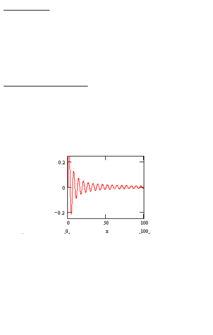
builder. The kit is built around a one-transistor oscillator made with Q1. This
oscillator is underdamped and is “struck” into oscillation by briefly raising the
voltage between R10 and R5. After the voltage between R10 and R5 returns
to normal, the oscillation dies out, as shown in the picture.
The effect is an exponentially decaying sine wave. An NE555 timer provides
the “striker” that gets the oscillator going. Every second or so the NE555
outputs a pulse that appears at the junction of R10 and R5. Then Q1 outputs
the waveform above which is fed to an audio amplifier. The result is an
output that sounds like a faucet drip or sometimes maybe a guitar string
pluck.

EDF1• 5
RAMSEY Learn-As-You-Build KIT ASSEMBLY
There aren’t that many solder connections on the EDF1 printed circuit board,
but you should still practice good soldering techniques.
•Use a 25-watt soldering pencil with a clean, sharp tip.
•Use only rosin-core solder intended for electronics use.
•Use bright lighting, a magnifying lamp or bench-style magnifier may
be helpful.
•Do your work in stages, taking breaks to check your work. Carefully
brush away wire cuttings so they don't lodge between solder
connections.
We have a two-fold "strategy" for the order of the following kit assembly
steps. First, we install parts in physical relationship to each other, so there's
minimal chance of inserting wires into wrong holes. Second, whenever
possible, we install in an order that fits our "Learn-As-You Build" Kit building
philosophy. This entails describing the circuit that you are building instead of
just blindly installing components. We hope that this will not only make
assembly of our kits easier, but help you to understand the circuit you’re
constructing.
For each part, our word "Install" always means these steps:
1. Pick the correct part value to start with.
2. Insert it into the correct PC board location.
3. Orient it correctly, follow the PC board drawing and the written
directions for all parts - especially when there's a right way
and a wrong way to solder it in. (Diode bands, electrolytic
capacitor polarity, transistor shapes, dotted or notched ends
of IC's, and so forth.)
4. Solder all connections unless directed otherwise. Use enough heat
and solder flow for clean, shiny, completed connections.

EDF1• 6
EDF1 PARTS LIST
Sort and “check off” the components in the boxes provided. We do our best to
pack all our kits correctly but it is possible that a mistake has occurred and we
missed a part. Please note that physical descriptions of parts are for those
currently being shipped. Sometimes the parts in your kit may have a different
appearance but still have the same values.
RESISTORS
1 2 ohm resistor [red-black-gold] (R9)
1 1K ohm resistor [brown-black-red] (R6)
1 2K ohm resistor [red-black-red] (R10)
2 10K ohm resistor [brown-black-orange] (R5)
2 47K ohm resistor [yellow-violet-orange] (R3,R4)
1 100 K ohm resistor [brown-black-yellow] (R1)
1 470K resistor [yellow-violet-yellow] (R7)
1 5K potentiometer [orange top marked 502] (R2)
1 100K potentiometer [orange top marked 104] (R8)
CAPACITORS
5 .01 uF ceramic disc capacitors [marked 104] (C2,C3,C4,C5,C10)
2 .1 uF electrolytic capacitor (C1,C11)
1 1 uF electrolytic capacitor (C13)
1 10 uF electrolytic capacitor (C8)
1 2.2 uF electrolytic capacitor (C6)
2 220 uF electrolytic capacitor (C9,C12)
SEMICONDUCTORS
Note: Chips may have other numbers and letters on them; the important num-
bers are those listed in brackets.
1 LM386N [marked LM386N-1] (U1)
1 NE555 Timer (U2)
1 1N4148 silicon diode (D1)
1 2N3904 (Q1)
MISCELLANEOUS
1 9V battery snap

EDF1• 7
EDF1 PC BOARD ASSEMBLY STEPS
Remember to save at least one clipped off component lead for use as a
jumper later in the construction process.
1. Let’s start with U2, the NE555 timer. The NE555 repeatedly starts the
oscillator that produces the dripping sound. Install it down at the bottom
middle of the board. Be sure to line up the notch on the board drawing
with the notch on top of U2 and be sure you’re not installing the other IC
(both have 8 pins)! Also be sure that all leads are through the board be-
fore soldering.
2. Next, install C13, 1 uF electrolytic capacitor, next to U2. Make sure its
polarity is correct. The “+” on the board has to line up with the positive
side of the cap. Usually, it’s the “-” side of the cap that is marked. The
other side is “+”.
3. Install C6, 2.2 uF electrolytic capacitor, next to C13. Watch polarity
again.
4. Install C12, 220 uF, electrolytic capacitor, above C6. Watch polarity.
5. Install R9, 2 ohm resistor [red-black-gold], above U2.
6. Install C11, .1 uF ceramic disc capacitor [marked 104], above R9.
7. Install U1, LM386N above C11. This is the audio amplifier that drives
the speaker you connect.
8. Install C8, 10 uF electrolytic capacitor above U1. Watch that polarity.
9. Install C9, 220 uF electrolytic capacitor, next to U1.
10. Install C10, .01 uF ceramic disc capacitor [marked 103], to the right of
U1.
11. Install R8, 100K ohm potentiometer [orange top marked 104], to the
left of U1.
12. Install C1, .1 uF ceramic disc capacitor [marked 104], to the left of U1.
13. Install C5 and C4, .01 uF ceramic disc capacitors [marked 103], to the
left of R8.
14. Install R2, 5K ohm potentiometer [orange top marked 502], to the left
of C4.
15. Install R3, 47K ohm resistor [yellow-violet-orange], under R2.
16. Install Q1, 2N3904 [marked, oddly enough, 2N3904], under R3.

EDF1• 8
17. Install R10, 2K ohm resistor, [red-black-red] under Q1.
18. Install R5, 10K ohm resistor [brown-black-orange], to the right of R10
19. Install C3, .01 uF ceramic disc capacitor [marked 103] next to R5.
20. Install R4, 47K ohm resistor [yellow-violet-orange], next to C3.
21. Install R1, 100K ohm resistor [brown-black-yellow], next to R4.
22. Install C2. .01 uF ceramic disc capacitor, under Q1.
23. Install D1, 1N4148 silicon diode, under C2. Be sure the band on the
diode lines up with the band on the board drawing.
24. Install R7, 470K ohm resistor [yellow-violet-yellow], under R5.
25. Install JMP1, under R7, using a little piece of cutoff component lead.
26. Install R6, 1K ohm [brown-black-red], under JMP1.
SETUP AND TESTING
Testing out the EDF1 is really easy. Just solder an 8 ohm speaker into the
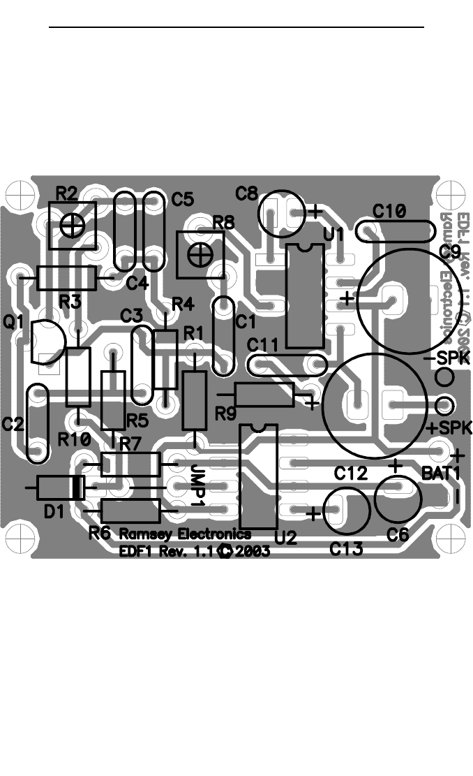
holes for the speaker which are located above the BAT1 pads. There’s no
silkscreen for these pads so you’ll need to look at the parts layout diagram
to determine the “+” and “-” holes. Solder the positive or red wire of your
speaker into the “+” SPK pad. Solder the negative or black wire of your
speaker into the SPK “-” pad. If your speaker doesn’t have “+” and “-” la-
bels, don’t worry, it will work fine anyway.
Solder in the 9V battery snap into the BAT1 pads. Now adjust R8 for vol-
ume and R2 for the decay time of the drip sound. Play with these two until
you get the most obnoxious sound possible. You can also twiddle with the
value of R1. If you want to run your EDF1 at lower voltages, you can re-
duce R1 to something like 220K. This will lengthen the sound and provide
a longer “drip”.
TROUBLESHOOTING GUIDE
If your kit doesn’t work it’s most likely a transistor put it wrong, or a polarized
component in backwards. Just make sure the transistor is lined up correctly
and the electrolytic caps are in the right way. If all this checks out, make sure
the right resistors are in the right places. Check your solder joints to be sure
they’re solid and look for solder splashes, solder bridges, cold solder joints or
unsoldered components.
EDF1• 9
EDF1 MAIN BOARD PARTS LAYOUT DIAGRAM

EDF1• 10

EDF1• 11
The Ramsey Kit Warranty
Please read carefully BEFORE calling or writing in about your kit. Most
problems can be solved without contacting the factory.
Notice that this is not a "fine print" warranty. We want you to understand your rights and ours too! All
Ramsey kits will work if assembled properly. The very fact that your kit includes this new manual is your
assurance that a team of knowledgeable people have field-tested several "copies" of this kit straight
from the Ramsey Inventory. If you need help, please read through your manual carefully, all information
required to properly build and test your kit is contained within the pages! However, customer
satisfaction is our goal, so in the event that you do have a problem, take note of the following.
1. DEFECTIVE PARTS: It's always easy to blame a part for a problem in your kit, Before you conclude
that a part may be bad, thoroughly check your work. Today's semiconductors and passive components
have reached incredibly high reliability levels, and its sad to say that our human construction skills have
not! But on rare occasions a sour component can slip through. All our kit parts carry the Ramsey
Electronics Warranty that they are free from defects for a full ninety (90) days from the date of
purchase. Defective parts will be replaced promptly at our expense. If you suspect any part to be
defective, please mail it to our factory for testing and replacement. Please send only the defective part
(s), not the entire kit. The part(s) MUST be returned to us in suitable condition for testing. Please be
aware that testing can usually determine if the part was truly defective or damaged by assembly or
usage. Don't be afraid of telling us that you 'blew-it', we're all human and in most cases, replacement
parts are very reasonably priced.
2. MISSING PARTS: Before assuming a part value is incorrect, check the parts listing carefully to see if
it is a critical value such as a specific coil or IC, or whether a RANGE of values is suitable (such as
"100 to 500 uF"). Often times, common sense will solve a mysterious missing part problem. If you're
missing five 10K ohm resistors and received five extra 1K resistors, you can pretty much be assured
that the '1K ohm' resistors are actually the 'missing' 10 K parts ("Hum-m-m, I guess the 'red' band really
does look orange!") Ramsey Electronics project kits are packed with pride in the USA. If you believe
we packed an incorrect part or omitted a part clearly indicated in your assembly manual as supplied
with the basic kit by Ramsey, please write or call us with information on the part you need and proof of
kit purchase.
3. FACTORY REPAIR OF ASSEMBLED KITS:
To qualify for Ramsey Electronics factory repair, kits MUST:
1. NOT be assembled with acid core solder or flux.
2. NOT be modified in any manner.
3. BE returned in fully-assembled form, not partially assembled.
4. BE accompanied by the proper repair fee. No repair will be undertaken until we have received the
MINIMUM repair fee (1/2 hour labor) of $18.00, or authorization to charge it to your credit card account.
5. INCLUDE a description of the problem and legible return address. DO NOT send a separate letter;
include all correspondence with the unit. Please do not include your own hardware such as non-
Ramsey cabinets, knobs, cables, external battery packs and the like. Ramsey Electronics, Inc.,
reserves the right to refuse repair on ANY item in which we find excessive problems or damage due to
construction methods. To assist customers in such situations, Ramsey Electronics, Inc., reserves the
right to solve their needs on a case-by-case basis.
The repair is $36.00 per hour, regardless of the cost of the kit. Please understand that our technicians
are not volunteers and that set-up, testing, diagnosis, repair and repacking and paperwork can take
nearly an hour of paid employee time on even a simple kit. Of course, if we find that a part was
defective in manufacture, there will be no charge to repair your kit (But please realize that our
technicians know the difference between a defective part and parts burned out or damaged through
improper use or assembly).
4. REFUNDS: You are given ten (10) days to examine our products. If you are not satisfied, you may
return your unassembled kit with all the parts and instructions and proof of purchase to the factory for a
full refund. The return package should be packed securely. Insurance is recommended. Please do not
cause needless delays, read all information carefully.

EDF1• 12
REQUIRED TOOLS
•Soldering Iron (WLC100)
•Thin Rosin Core Solder (RTS12)
•Needle Nose Pliers (MPP4 or RTS05)
•Small Diagonal Cutters (RTS04)
ADDITIONAL SUGGESTED ITEMS
•Helping Hands Holder for PC Board/Parts
(HH3)
•Technician’s Tool Kit (TK405)
•Desoldering Braid (RTS08)
TOTAL SOLDER POINTS
77
ESTIMATED ASSEMBLY
TIME
Beginner .............. 2 hrs
Intermediate ......... 1 hrs
Advanced ............ . .30 min
RAMSEY ELECTRONICS, INC.
590 Fishers Station Drive
Victor, New York 14564
Phone (585) 924-4560
Fax (585) 924-4555
www.ramseykits.com
TABLE OF CONTENTS
Introduction to the EDF1 .................................... 4
EDF1 Circuit Description ................................... 4
Parts List ............................................................ 6
Assembly Steps ..................................................7
Setup and Testing .............................................8
Troubleshooting Guide .......................................8
EDF1 Parts Layout Diagram ...............................9
EDF1 Schematic ...............................................10
Ramsey Kit Warranty ........................................11
