Ranch Systems RS100 RanchSensor User Manual Manual 7 19 06 JC REVISED
Ranch Systems LLC RanchSensor Manual 7 19 06 JC REVISED
Owners Manual

1
FCC Statement
This equipment has been tested and found to comply
with the limits for a class B digital device, pursuant to
part 15 of the FCC Rules. These limits are designed to
provide reasonable protection against harmful
interference in a residential installation. This equipment
generates, uses, and can radiate radio frequency energy
and if not installed and used in accordance with the
instructions, may cause harmful interference to radio
communications. However, there is no guarantee that
interference will not occur in a particular installation. If
this equipment does cause harmful interference to radio
or television reception, which can be determined by
turning the equipment off and on, the user is encouraged
to try to correct the interference by one or more of the
following measures:
• Reorient or relocate the receiving antenna
• Increase the separation between the
equipment and the receiver
• Connect the equipment into an outlet on a
circuit different from that to which the receiver
is connected
• Consult the dealer or an experienced radio/TV
technician for help
This equipment has been verified to comply with the
limits for a class B computing device, pursuant to FCC
rules. Operation with non-approved equipment is likely
to result in interference to radio and TV reception. The
user is cautioned that changes and modifications made
to the equipment without the approval of the
manufacturer could void the user’s authority to operate
this equipment.
RanchMaster System Manual
2
WARNING – READ BEFORE USE!
Congratulations on choosing the RanchMaster system
for your business. We believe that RanchMaster is the
most advanced technology available today for
agricultural irrigation and climate control.
However, it is important to emphasize that this system is
still only a tool, and cannot be expected to function error-
free, 100% of the time.
The following are just some of the risks and limitations
that you need to plan for:
• Control and Data information is communicated via
cellular networks, such as Cingular. These network
experience outages, which in turn will prevent the
RanchMaster system from working
• Sensors occasionally report erroneous values, so
ultimately no data value can ever be assumed to be
100% true. Sensor data is a proxy for real conditions
in the field, but ultimately you should never take
drastic actions before double-checking specific
conditions.
• Electrically operated valves may malfunction, so for
example, the RanchMaster system may report a valve
as open when in fact the valve itself is still closed.
Correlating to water flow and soil moisture sensors
are good ways to detect such problems.
• No piece of software is error-free, despite thorough
testing. This means that RanchMaster system may
perform incorrect and unexpected actions, such as
opening a valve without explicit instructions. The user
must be vigilant in monitoring such anomalies to
avoid loss or damage. RanchMaster sensors can
themselves help implement such “closed loop”
verification, but it ultimately remains the ranch owner
responsibility.

3
Limited Warranty
Ranch Systems does not warrant that the RanchMaster
solution will operate uninterrupted or error free. Ranch
Systems will use commercially reasonable efforts to
correct any RanchMaster Solution problems in a timely
manner upon identification of issue or receipt of notice.
If a customer is dissatisfied with the equipment and
service within the first 90 days of equipment installation
and activation, they may terminate service.
Limited Liability
Ranch Systems shall not be liable for direct, indirect,
incidental or consequential damages including without
limitation damages for harm to business, lost profits or
lost revenues (however arising, including negligence),
whether or not Ranch Systems has been advised of the
possibility of such damages. Ranch Systems shall not
be liable for any damage that may arise out of use, or
inability to use, the services or products provided
hereunder.
RanchMaster System Manual
4
RanchMaster System
Manual
Version 2.1
Copyright © 2006 Ranch Systems LLC
All Rights Reserved

5
Table of Contents
CHAPTER 1 – GETTING STARTED 7
1.1 Introduction 7
1.2 Features of this manual 7
CHAPTER 2 – ABOUT YOUR SYSTEM 9
2.1 RanchMaster System Overview 9
2.2 Sensor Node Specifications 14
2.3 Base Station SpecificationsError! Bookmark not defined.
2.4 Hosted Software SpecificationsError! Bookmark not defined.
CHAPTER 3 - INSTALLATION 17
3.1 What You Have Received 17
3.2 Base Station Installation 18
3.3 Solar Panel Installation 20
3.4 Sensor Node Installation 20
3.5 Sensor Installation 21
CHAPTER 4 – BASE STATION USAGE 20
4.1 Introduction to manual base station usage 20
4.2 Base station keypad overview 20
4.3 Menu Options 22
CHAPTER 5 – INTERNET SOFTWARE 30
5.1 Logins & Security 30
5.2 Online Features 30
5.3 SMS Commands 46
CHAPTER 6 – TROUBLESHOOTING 46
6.1 Trouble Shooting Overview 46
CHAPTER 7 – CUSTOMER SERVICE 50
RanchMaster System Manual
6
7.1 Customer Service 50
7.2 Contact Information 50
GLOSSARY 51
CONTACT INFORMATION 55

7
Chapter 1 – Getting Started
1.1 Introduction
This manual describes the use of the RanchMaster
system, including base station, wireless sensor
nodes, and corresponding web software.
1.2 Features of this manual
This manual contains 7 chapters intended to
explain the features and functions of Ranch
Systems equipment.
Chapter 1 – Getting Started
A preview of the manual
Chapter 2 – About Your System
Overview of RanchMaster system components
and technical specifications
Chapter 3 – Installation
Itemizes your RanchMaster system components
and explains the proper methods for setup of
each component
Chapter 4 – Base Station Software
Instructions for the setup and navigation of the
RanchMaster base station
Chapter 5 – Internet Software
RanchMaster System Manual
8
Instructions for the setup and navigation of the
Ranch Systems website and how to use it in
conjunction with the base station
Chapter 6 – Trouble Shooting
An explanation of error messages, hardware
issues and FAQs
Chapter 7 – Customer Service
A list of contact information to get in touch with
Ranch Systems personnel
Glossary
Definitions of frequently used terms
9
Chapter 2 – The RanchMaster System
This chapter introduces you to the specification and
operational principles of the RanchMaster system.
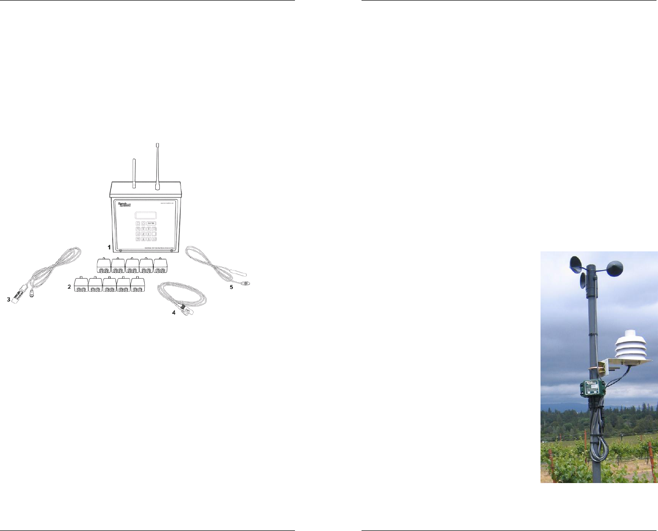
2.1 RanchMaster System Overview
RanchMaster is a powerful, easy-to-use, system for
wireless climate and irrigation control, optimized for use
in agriculture. Typical hardware components of a
RanchMaster system are shown in the picture above:
1. Wireless base station (typically one, but possibly
multiple per system)
2. Wireless sensor nodes (typically 4-100 per
system)
3. Soil moisture sensors
4. Flow sensors
RanchMaster System Manual
10
5. Temperature sensors
Other sensors supported but not pictured include:
1. Relative humidity sensors
2. Wind speed sensors (anemometer)
3. Rain gauges (tipping bucket style)
4. Water level and pressure sensors
5. Electric valves
6. Leaf wetness sensors
2.2 Sensor Nodes
Wireless sensor nodes are small, completely self-
contained units encapsulated in a rugged, water-tight
metal enclosure. Each node
has two input ports to which
various sensors can be
attached. Nodes come pre-
programmed to accept a
particular set of sensors on
their ports, so there is
absolutely no field
programming required. They
also come already powered
up, and their built-in battery
will keep them running for 2-
3 years depending on sensor
types attached. The types of
sensors attached to sensor
nodes include: soil moisture
sensors, water flow sensors,
wind speed gauges, and
relative humidity sensors.
Additionally, all sensor nodes
have a built-in temperature

11
sensor.
Sensor nodes are not data collection devices – they are
sensor monitoring devices. This distinction is important
to understand the functioning of a RanchMaster system:
whereas a data collection device periodically reads data
from a sensor and transmits or stores this data, sensor
monitors only report exceptional conditions. The
important fact about the RanchMaster system is that
using sensor monitoring it is possible to establish a
virtual data series of sensor data using complex
approximation and projection techniques. The result is
better data at dramatically lowered battery use due to
minimal wireless data transmission in the field.
Ranch Systems sensor nodes accomplish this by being
programmed to understand the specific meaning of
attached sensors and only transmit to the base station
when a significant event occurs, which is typically a
major change in the conditions. For example, in the case
of a sudden temperature drop, the sensor node will
realize that this needs to be reported and some action
may need to be taken. It will transmit the new value to
the base station with instruction to connect to the back-
end server and rules engine. The rules engine will
determine the necessary response and transmit back to
the base station. The original signal from the node will
also contain instruction to the base station to show the
new value in the display as an alert and possibly take
direct action locally (even without contacting the server).
More specifically, this event-based scheme works as
follows: the sensor node continuously monitors the
attached sensors and their latest values. It compares
this to the past pattern of values and determines when
the value of the sensor represents an abnormal situation,
in which case a control signal is transmitted to the base
station reporting this change and instructing the base
station to take further action as described above. Note
that the sensor node and base station maintain a mutual
RanchMaster System Manual
12
“contract” as to the normal sensor value pattern, so
transmission need not occur just because a sensor value
changes – only if the value change is “abnormal” will
transmission occur.
For example: let say a sensor node is measuring soil
moisture. When the soil is irrigation the soil moisture will
increase rapidly, and this sudden event will be reported
to the base station. However, after irrigating, the soil
moisture will decrease slowly following logarithmic
function. Because the sensor node and base station
understands this function, no further transmission need
occur until next abnormal event (start of rain, or
irrigation).
The effect of this scheme is that at times when sudden
events lead to rapid fluctuations in sensors value (like
start of irrigation changing soil moisture), the nodes will
transmit often to signal these abnormal conditions, while
at other times when no particular events are occurring,
no data will be transmitted for long periods of time.
The sensor nodes have a mechanism to prevent
frequent transmission and associated battery drainage in
the unlikely situation that a sensor changes value rapidly
and randomly (e.g. a malfunctioning sensor). This is
accomplished in three complementary ways: 1) by
ensuring that at least 2 minutes pass between any to
transmission cycles, even in the most extreme case, 2)
by randomizing the interval of time between any two
transmissions, and 3) by a “lock-out” rule that disables a
sensor that has reported a dramatic change more than a
certain number of times per hour.
2.3 Base Stations
Wireless base stations are rugged, self-contained
wireless units placed centrally in the general areas
where sensor nodes are deployed - typically on a

13
pole. The range around the base station for reliable
deployment of sensor nodes should not exceed 1/2
mile under line-of-site conditions. Base stations are
powered by a small solar panel and are contains
four electrical relays capable of switching a variety
of electric valves. In general, base stations perform
a number of distinct functions:
• they act as real-time conrol data
companions for sensor nodes, maintaining
“normal data pattern” contracts with each
sensor node and forwarding control and
data information back and forth to the
backend server
• they act on commands issued from the
Internet server, such as opening and
closing of electric valves
• they act on text messages (aka SMS) sent
to them by users in request of latest sensor
status information or with commands to
open or close valves
• they can monitor sensor data from attached
sensors, in much the same way as sensor
nodes
Base stations constantly approximate real-time data
conditions in the local network based on exception
signals and data
received from the
sensor nodes. When
exceptional changes in
data occurs,
transmission link is
immediately
established to the
back-end server via the
cellular network.
Base stations process
RanchMaster System Manual
14
commands received via text messaging (aka SMS).
These commands can either be issued by an end-
user using a cellular phone, via the Internet
software as a response to users selecting control
options, or by the triggering of advanced rules
programmed by the end-user. Commands fall in
three broad categories:
• Informational commands, such as
requesting information about the latest
value of a particular sensor
• Control oriented commands, such as
requesting the opening of a particular valve
• System-level command, such as updating
the base station system configuration.
Base stations also have the ability to monitor
sensors connected directly. This is especially useful
for sensors that require more power than can be
derived from the small battery in sensor nodes, or
sensors that need constant excitation. There are
five sensor ports: 1 digital port, 2 analogue ports,
and 2 digital counter ports.
Finally, the four on-board relays themselves are
also sensors enabling the positive confirmation that
a command to open a valve has in fact been
executed.
2.4 Technical Specifications
Wireless Sensor Node – RS100
• Wireless connectivity to RM100 stations (up to
1/2 mile) via Ranch Systems VHF Ranch Area
Network (‘RAN’) protocol
• One 2.5V excitation analog input port

15
• One 5V excitation analog input port
• Built-in temperature sensor
• Powered by 3.6V lithium cell (~2-3 years life)
• Self-monitoring battery status to Internet
software
• Rugged, watertight aluminum enclosure
Cellular Base Station – RM100C
• Receiver for Ranch Systems VHF ‘Ranch Area
Network’ (RAN)
• Transceiver for GSM cellular packet data to
Ranch Systems network operating center
(NOC)
• Transceiver for SMS text messaging protocol of
GSM network
• 4 built-in relays for driving valves or other
equipment
• 2 analog input ports (5 or 12V excitation)
• 1 digital input ports (0-5V)
• 2 digital counter ports (0-5V)
• Built-in temperature sensor
• 4 line LCD display with backlighting
• 15 key waterproof keypad
• Battery and 12V solar charge controller
• Wall charger for 120 VAC
• Enclosure of 14 gauge steel, NEMA 3R rated
WiFi Base Station – RM100W
Identical to RM100C except:
RanchMaster System Manual
16
• No cellular modem
• Built-in 802.11b card for connectivity via WiFi
access point.
Hosted Software Suite
• Automatic communication with RM100 stations
and RS100 nodes
• Incorporates customer-specific clickable map
photo to show overview of Ranch Area Network
(‘RAN”)
• Configurable ’dashboard’ with latest values for
all sensors and direct access to pop-up graphing
• Reporting module with PDF-quality, detailed
reports
• Control-zone grouping of sensor into natural
irrigation and management zones
• Rules engine allowing simple or complex rules
and triggers
• Unlimited central database storage
• Cellular phone interface using text messaging
(SMS) for controls and alarms
• 100% accessible from any Internet browser
• Secured by SSL encryption
• Database and application hosted in two
separate high-security data centers with nightly
backups and diesel generator power backups.

17
Chapter 3 - Installation
3.1 What You Have Received
Your RanchMaster system comes equipped with a base
station, at least four wireless sensor nodes, a solar
panel, a wall charger, and associated sensors. There
are a myriad of alternate sensors that can also be used
in conjunction with the base station. Your selected
components are itemized on the inventory sheet shipped
with your system.
Our Ranch Systems technicians have pre-packaged the
base station and sensor node units with their associated
sensors for your convenience. This typically includes a
refitting of sensors with Ranch Systems bayonet style
connectors for increased field reliability. Please refer to
the unit labels to unsure sensor connection to the
appropriate ports on the nodes.
Each node is identified by and serial number printed on
the front of the node, e.g. “1014”. The left plug on the
node is referred to as “port 1” and the right plug is “port
2”. In the software you refer to sensors using the serial
number + the port number separated by colon. So a
sensor in port 2 on node 1014 would be referred as:
“1014:2”.
Once installed, all of these components can be reviewed
and managed using the Ranch Systems website
(www.ranchsystems.com), for which you will receive a
username and password separately.
RanchMaster System Manual
18
3.2 Base Station Installation
The first and most important component to set up is the
base station. It is imperative that the base station be set
up in a central environment, out of the way of machinery
and casual tampering, with a good cellular connection
(refer to Chapter 4 for additional detail about testing
cellular signal strength), and accessible to technicians
for support if required.
The maximum range from the base station to the sensor
nodes is approximately half a mile, line-of-sight. Nodes
outside that range will have problems transmitting data,
which will compromise the functionality of the
RanchMaster system. Ideally, the base station should
be placed in an area that has “line of sight” to all of the
nodes that it controls, however there is some flexibility
based on distance from the base station and site-specific
conditions. Please contact a Ranch Systems technician
if you have any questions about base station placement.
Note: if your site has complex topology, it may be
necessary to order a RanchMaster base station with an
external antenna, which can be separately mounted on a
mast.
The base station is shipped with the main fuse
disconnected (located separately in your packaging), so
to start operation this fuse must first be inserted. To
accomplish this, remove the two screws along the lower
front edge of the unit and carefully slide the front-plate
down and up. BE CAREFUL NOT TO PULL THE
KEYBOARD CABLE OUT OF ITS SOCKET. You will
then see a small socket in the lower left corner of the
circuit board into which the supplied fuse will fit. As soon
as you insert the fuse, the station should start up, and
you can immediately replace the cover.
19
After the base station is installed you must verify that it is
functioning. Once the system is turned on, it should
instantly begin to synchronize with the server. Give it a
few minutes to get connectivity and synchronize before
starting to troubleshoot. This is a good time to get
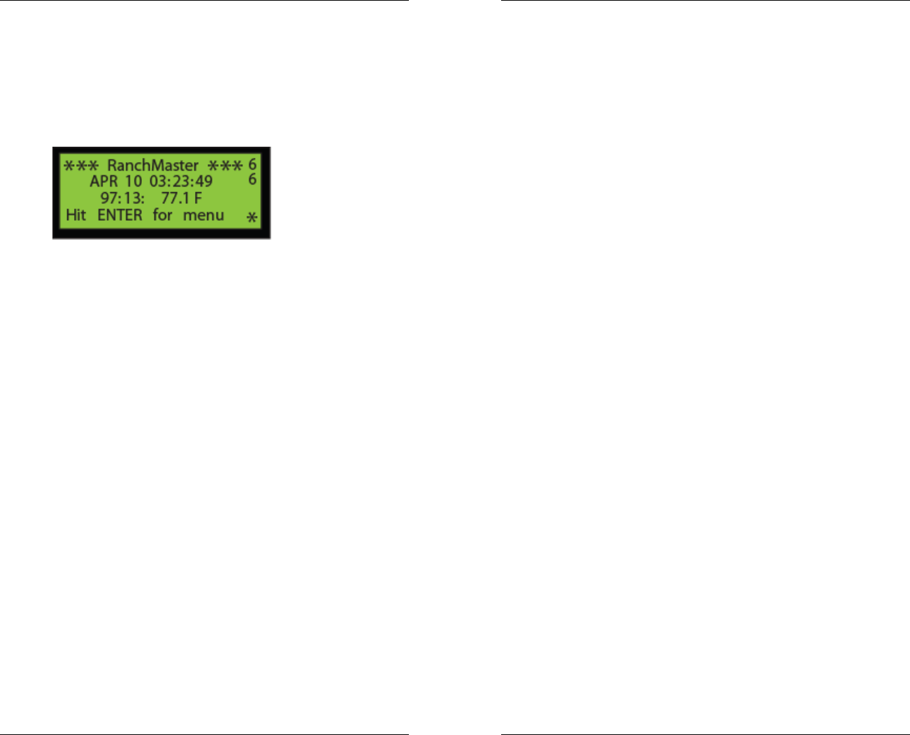
familiar with the Base Station display:
The number in the upper right hand corner of the screen
marks the cellular signal strength. The number 9 marks
the highest signal strength possible, whereas a zero
would mark no signal being received. Typically a signal
of 3 is sufficient, although 4 or 5 are preferable.
The number directly below this one on the screen
indicates the connection status of the base station. The
meaning of this number is as follows:
1-3 No connection, typically when there is
insufficient cellular coverage. If this is the
problem, either relocate the station to a place
with better strength, or contact Ranch Systems,
as a high-gain cellular antenna can be fitted to
improve signal performance.
4 Idle state – base station is connected to the
cellular network, but not communicating with
Ranch Systems server
5 Not used
6 Base station is in process of connecting with the
Ranch Systems server (Network Operating
Center).
7 Data and control information is being
synchronized with the server.
RanchMaster System Manual
20
When you first initialize the base station, the cellular
signal strength will appear as a dash (-) and the station
connection will likely be a 2. The time and date will likely
be inaccurate as well. As the system begins to boot up,
the cellular signal strength will show up as a number,
and the station connectivity should jump from 2 to 4 to 6
and eventually briefly 7. If the time of the unit is not
correct the system will discover this at this point and time
will be adjusted and unit reset automatically.
At this point the base station is running and receiving
sensor information from nodes, and there is typically no
more field programming to perform. All the programming
of functionality is done in the Internet software.
3.3 Solar Panel Installation
The solar panel is needed to charge the battery of the
base station. It should be mounted as high as possible,
however such that it is accessible for maintenance if
needed. The solar panel should be placed facing the
sky southward, at an angle. The optimal angle depends
on the latitude of your location, however a 45 degree
angle should work for most locations.
3.4 Sensor Node Installation
Depending on the number of sensors attached to each
node, and the variability of the data sensed, as many as
100 sensor nodes may be set up for each base station.
These sensor nodes process the information from the
sensors you have selected, and transmit exceptional
changes back to the base station based on a complex
monitoring and control scheme outlined in the
introduction. Nodes should be placed around the

21
property in the locations where you desire to monitor
sensor data.
The sensor nodes need to be placed upright, with the
antenna facing vertically toward the sky. The higher up
the node is placed, the better it will transmit to the base
station. A typical installation will place the node on a
stake just above an irrigation line, with any sensor
cables that run to the ground routed downward through a
PVC pipe. Please note that it is important to ensure that
the sensor cables remain relatively straight at their
connection as severe bends can damage both nodes
and sensors.
The sensor node can be attached in the desired position
using the flanges located on either side of the metal shell.
It is important to make sure that the sensor node is
secure and will not be removed by violent weather or
machinery.
Please note that sensor nodes come pre-configured for
specific sensors, which is printed on the front plate of the
nodes. This means that you have no programming or
configuration hassle during installation, but it also means
that you must order the correct nodes for your sensors.
3.5 Sensor Installation
The RanchMaster system works with a range of sensors
such as temperature, soil moisture, water flow, water
level, humidity, and wind speed. If your current
configuration does not include your preferred sensors, or
if you would like to interface with an existing sensor,
please speak with one of our Ranch Systems
technicians.
Each sensor has its own specific method for installation.
Please review the manual for the specific sensors that
RanchMaster System Manual
22
you are using, or contact the manufacturer for
instructions on how to install your sensors. The Ranch
Systems staff is also available to give advice.
23
Chapter 4 – Base Station Usage
4.1 Introduction to manual base station
usage
The majority of the time users will simply review and
control the base station and overall RanchMaster system,
via the Internet, which provides both ease of use and
advanced functionality. Users can also control and
adjust the system directly, however, using the base
station keypad and LCD.
Common direct uses of the base station keypad and
LCD include monitoring the most recent values of
sensors to check that the system is working and all
nodes are communicating as expected, manually
controlling any connected valves, and reviewing various
system functions (mostly intended for service personnel).
4.2 Base station keypad overview
The top row of the keypad contains the following three
buttons which you will use for most of the navigating.
The up and down arrow keys that will move your cursor
location, and the “ENTER” key that selects prompts and
engages processes.
The arrow key which faces leftward is used to go back to
the previous screen, and is also used as a delete key
when entering in numeric values.
RanchMaster System Manual
24
The numeric keys are used to enter values. The period
key (located directly under the leftward arrow/back key)
is used to enter decimals into numeric entries. It also
serves as the refresh button when a menu or list is
shown. The base station does not automatically update
the screen display, so it is generally necessary to refresh
the screen to see that an operation has been performed
or some anticipated sensor condition changed.
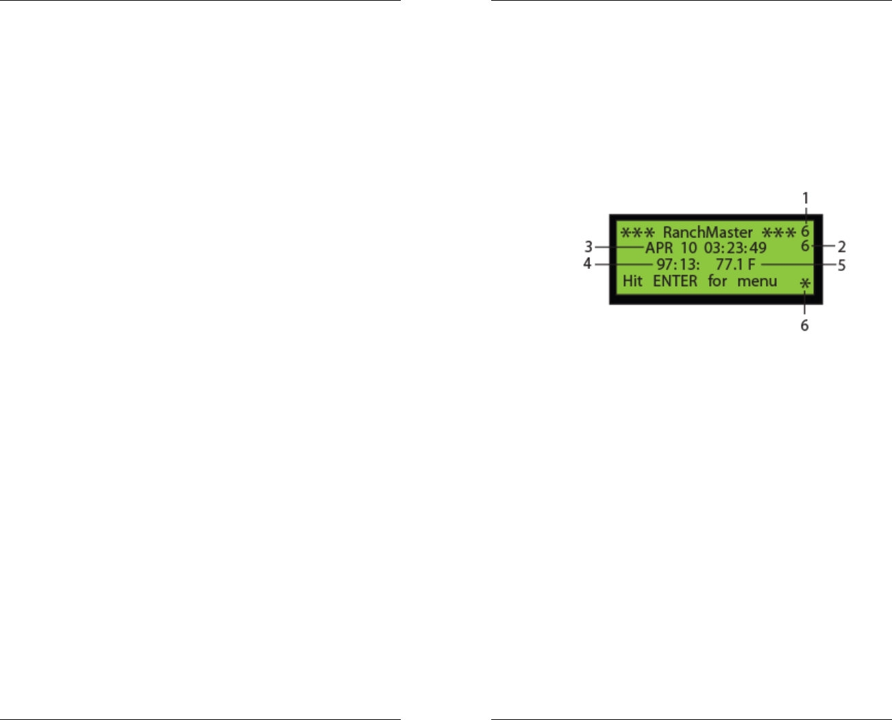
The primary screen, which is displayed initially when the
base station is first turned on, provides information about
the time, the attached sensors, and the cellular signal
strength:
1. The number in the upper right hand corner of the
screen marks the cellular signal strength, where
the number 9 is the strongest signal and 0
indicates no signal.
2. The number directly below this one on the screen
indicates the connection status of the base station.
The base station synchronizes changes in sensor
data with the central server on a real-time basis.
When this number is a 4, that means that there is a
connection, however nothing is currently being
exchanged. When the base station is attempting
to sync with the server, this number will change to
a 6. When the base station is finalizing the

25
synchronization (this occurs briefly), this number
will change to a 7 and then return to a 4. Any
number below a 4 indicates that there is a
connection problem. For a more detailed look at
the cellular signal strength and the connection of
the station please view chapter 3.
3. Directly underneath the “RanchMaster” Title, the
date and time are displayed.
4. Below this line is a scrolling display of the various
sensors associated with the base station either
directly or through a sensor node. The number on
the left identifies the sensor using the RSUID:port
code that corresponds to the base station or
sensor node unit and the port to which that specific
sensor is attached. This same number will be
notated on the Ranch Systems Website as the
“Sensor ID” and is used to identify any sensor.
Note: RSUID stands for Ranch System Unit ID,
and is essentially the serial number of the node or
base station.
5. The value to the right of the RSUID:port code
corresponds to the most recent measurement or
status of the sensor indicated by that code. Valves
will be marked as “OPEN” or “CLOSED”, wind
speed will be displayed in terms of “m.p.h.”,
batteries will be displayed in terms of voltage,
temperature will be displayed in terms of degrees
Fahrenheit, etc… The values will change every
couple of seconds, allowing the system to scroll
through all of the active sensors.
6. In the bottom right hand corner of the screen there
is a flashing asterisk. This is the “heart beat” of the
base station, which indicates simply that it is on
and working.
4.2 Menu Options
RanchMaster System Manual
26
In order to access the Menu from the primary screen,
press the “ENTER” key. This will take you to the main
menu screen, which is divided into nine subdivisions:
1. Sensor Status
This menu lists all of the active units by their RSUID
codes with the most recent known status.
Using the arrow keys to move the cursor through the list,
a specific unit can be selected by clicking “ENTER”
when the cursor is on the desired row. This next level of
detail lists out all of the ports associated with the unit,
what sensor type is present on that port, and the latest
sensor value. This information is displayed as follows:
• “Prt” - The Port #
• “Tp” – The Type of Sensor
oFL = Water Flow
oHM = Humidity
oSM = Soil Moisture
oTP = Temperature
oWS = Wind Speed
o3V = Internal Lithium Battery (ranges
from 3-3.5V)
o5V = Sensor Voltage Generator (should
be at ~5V)
oCF = Configuration (diagnostic
information used by the NOC to monitor
unit performance)
• “Mn” – Minutes since the last read
• “Value” – The most recent reading of the sensor
In order to get a more in-depth display, simply press the
“ENTER” button on the port/sensor you wish to view.
This will display a menu with RSUID and port #, the type
reference number and type description, the last known
time, and for base station sensors only, the sampling
rate. Use the arrow key to scroll down to see additional
information that does not fit on the screen
2. Valve Control

27
This menu lists the various active valves that are linked
to your base station. It displays the “RSUID” which
shows the RSUID:port codes of your valves, the “Type”,
and the “Stat” or Status. Valves can be one of two type
categories: Type “LATC” represents a valve with latching
DC solenoids, and Type “N.O.” represents “Normally
Open”, i.e. a valve that simply gets switched through a
normal relay function, such as standard 24VAC valves.
The type of valve is determined by jumpers on the circuit
board and should be set by qualified service personnel
to fit the particular valves connected to the RanchMaster
relays. Both of the valve types can be open or closed on
command. “Stat” or Status displays whether or not the
valve is on or off. In order to turn a valve on or off,
simply move the cursor next to the RSUID:port code of
the valve you wish to change and hit enter. A new
screen will show titled “Select and ENTER” in which you
can choose whether the valve should remain on or off by
selecting the prompt and pressing “ENTER”. After you
have made your selection and pressed “ENTER”, use
the back arrow to return to the previous menu(s).
Note:
Valves relays are assigned port number 10 through 13,
where relay 1 (from left on circuit board) is on port 10,
relay 2 on port 11 and so forth.
3. Memory Status
This menu lists the sensor (“data recs”) and message
(“msg”) reads and what percentage of memory they are
using (%). The last upload records the last time that this
menu was updated.
•
••
•
Data: Data records currently buffered in the
base station. These are control records with
information about exceptional sensor conditions.
•
••
•
Sensors: Number of unique sensor known to this
base station
•
••
•
RSUIDs: Number of unique nodes known to this
base station (including the base station itself)
RanchMaster System Manual
28
•
••
•
Sync: Last time base station synchronized with
Ranch Systems Network Operations Center
(NOC)
•
••
•
Log: Number of system log entries currently
buffered in base station
•
••
•
UserNames: Internal field for system use only
•
••
•
Tsynch: Time of last synchronization of base
station’s real time clock from the Ranch Systems
Network Operations Center (NOC)
4. Synchronize
This selection causes the base station to synchronize
with the server immediately. When selected, the base
station will pre-empt its normal synchronization schedule
and immediately synchronize with the Ranch Systems
data center. This function is not normally required, and
the system automatically maintains real-time consistency.
5. Configure
This menu lists the various system-level settings that are
typically only used by Ranch Systems Technicians.
The following is a list of the abbreviations, their
meanings, and a brief definition:
• RSUID – The identification number of the base
station
• IP – This number shown is the IP address
specific to the Ranch Systems server to which
the base station will synchronize.
• IP2 – This is the address for the back up server.
The base station will connect to this server if the
first one cannot be reached.
• GSM – This is the GSM phone number of this
base station. This is the number to which you
can send SMS commands and messages. The
base station will automatically update this field
based on the specific SIM card inserted.
• AGSM – This stands for administrative GSM. In
the case of an emergency, the base station will

29
send an SMS message to the Ranch Systems
administrator.
• APN – This is the access point for the GPRS
network
• APNUN – The Username for the APN server
• APNPW – The password to access the APN
server
• Servertime – This field allows you to choose
how often the base station should update its
real-time clock from the servers’ time and date.
In order to change this setting, press “ENTER”
on the “Servertime” prompt. The value entered
here is the number of minutes between server
time synchronization.
• Lcddatarate – This is number of seconds
between updates in the main screen. In order to
change this value, simply press “ENTER” on the
“Lcddatarate” prompt. Then using the key pad,
type in the new value and press enter.
• Wifion – NOTE: Applies to model RM100W only,
and enables the formation of ad-hoc networks of
multiple base stations over larger(multiple miles)
distances. Do not change.
• Cellon – Cellular on: This is the most common
mode of communication between base stations
and the Ranch Systems server. In order for the
base station to synchronize it needs to send and
receive cellular signals, so this signal should not
be changed.
• Msgmode – This is the messaging mode. This
determines to what degree the system
messages are uploaded. A value of “0” denotes
that none of the system messages will be
uploaded. A value of “1” lets only critical
messages upload. A value of “2” allows for all of
the messages to upload. In order to change this
value, simply press “ENTER” on the “Msgmode”
prompt. Then using the key pad, type in the
new value and press “ENTER”.
RanchMaster System Manual
30
• Syncrate – This menu lets you set the interval
of time that the base station synchronizes with
the server. Not normally necessary as the base
station will automatically synchronize as needed.
• Rdvrate – This refers to the Rendezvous rate;
or how often the multiple base stations
synchronize. This is only relevant if you are
operating with two or more base stations. An
average suggested Rdvrate is 5 minutes.
• Rdvsecs – This refers to the length of time in
seconds that the base stations will utilize during
a rendezvous. An average suggested rate is 60
seconds.
• Rxshow – This refers to the “S” text icon shown
in the lower right hand of the LCD display. An
“S” will occur when sensor data is being
received. A value of “1” in this category means
that this icon will be displayed on the main LCD
screen. A value of “0” will hide it.
• SMSon – This menu commands the base
station to check for inbound SMS commands. A
value of “1” allows SMS messages to be
received. A value of “0” causes the base station
to ignore these SMS messages. NOTE: turning
SMS off, will also disable the control of valves
from the Internet software.
6. System
This menu is designed for maintenance and repair. It is
intended for use by Ranch Systems Technicians only.
• System Log – This is system event information
regarding the base station.
• RSRF Track – This selection allows you to type
in the RSUID from a single specific node, and
see a real-time log of signal received from that
node.
• RSRF Scan – This selection is used only by
authorized service personnel during site analysis

31
and installation, allowing advanced wireless
signal diagnostics and troubleshooting.
• RSRF Status – This menu provides advanced
system information regarding the RSRF (Ranch
Systems Radio Frequency) subsystem.
• Switch Servers – This menu allows the base
station to switch its synchronization to the
alternate server.
• Recycle board IO – This is an administrative
function to reset the base station IO chips.
• Device status – This provides a status check of
certain peripheral devices on the base station
• Reset (soft) – This menu resets and
resynchronizes the base station.
• Reset (w/erase) – This menu resets,
resynchronizes, and erases the memory of the
base station.
7. Current Time
This menu provides you with the current date and time
settings of your base station. If you want to adjust any of
the settings manually regarding the date and time you
can do so in this menu by lining the cursor up with either
“date” or “time” and pressing “ENTER”. The screen will
then display the first prompt (In the case of the date it is
the “year”). Simply press “ENTER” to navigate through
the prompts until you find the one that you want to
change. Use the left arrow to delete the current entry
and enter a new one with the numeric pad. When you
are finished press “ENTER”. Remember that in order for
your own personal date and time settings to remain, you
must first change the value to 0 in the Servertime
category of the Configure menu, however, generally it is
preferable to let the base station automatically
synchronize time from the Ranch Systems server.
8. Signal Strength
This menu displays the signal strength and the error
rate. The error rate deals with the number of times that
data packages are sent before actually getting received.
RanchMaster System Manual
32
The cellular GSM protocol detects errors, and when this
rate is high it has to resend the data. The scale is
between 0 and 7, with 0 meaning that no messages are
resent, and 7 meaning that messages are constantly
resent, indicating either poor connection or interference
from other equipment.
9. SW Version
This menu displays the specific version of software that
is installed on your base station.
33
Chapter 5 – Internet Software
One of the unique features of the RanchMaster
solution is the ability to monitor and control your
entire system from anywhere in the World – at any
time. All you need is access to an Internet browser.
It also means that data is always kept secure in the
Ranch Systems Data Center, and that system
problems, such as viruses, located on your own
computer systems will not affect the integrity of your
RanchMaster system and data.
5.1 Logins & Security
In order to login, simply go to the Ranch Systems web
site (www.ranchsystems.com) and follow the “My
Account” link in the left menu bar. This will take you to a
secure login screen. Your Property ID, User ID and
password will be provided either by Ranch Systems or a
Ranch Systems Authorized Dealer.
Property ID is a short mnemonic identifying the property
you wish to log into. User ID is your personal user name
on the Ranch Systems network. The same users can
have accounts on multiple properties (such as an
outsourced vineyard manager), and one property can
have several users. If you are having problems logging
in, please contact Ranch Systems technical support.
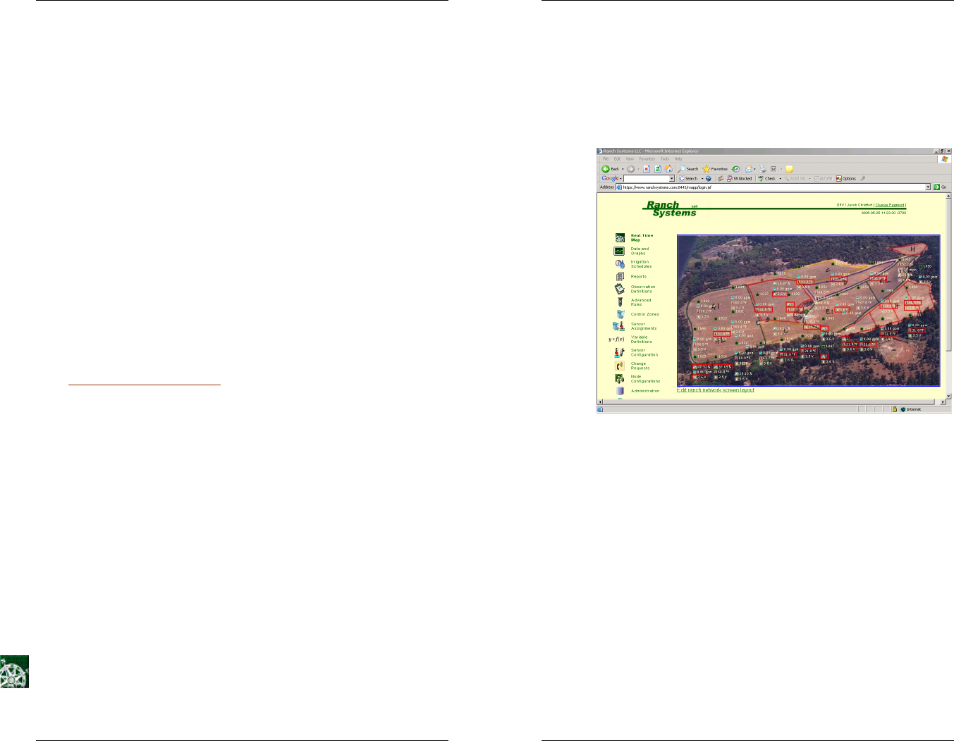
5.2 Online Features
Real-Time Map - This page displays a photographic
layout of your monitored area and divides it into zones.
RanchMaster System Manual
34
Within this area, your various sensors are displayed as
small icons located roughly equivalent to their actual
location in the field. Each sensor on the map will display
its last read value next to its icon. If the last value is
outside of the range set in sensor configuration, it is
highlighted by a red box.
Photo courtesy of Obsidian Ridge Vineyard (www.obsidianridge.com)
For a more in-depth look at sensor data simply click on a
specific sensor or anywhere within a block. This will pull
up a graph portraying time series data of either a specific
sensor or all the sensors in a block.
NOTE: because of the complex method used by
RanchMaster to monitor sensors, the graphs don’t
represent simple periodic time series of data like
traditional data loggers. Instead it is a result of
monitoring and approximation performed between
sensor nodes and base station, rather than periodic
transmission. In many cases this is in fact more precise
than periodic measurement. Please see introduction for
more information on this method.
35
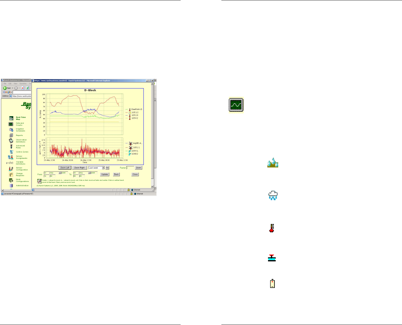
Once in the graph view, you can customize the chart
using the pull down menu to select the amount of time
you would like to graph. You can select preset values
from the last hour up to the last year of stored data. You
can also customize the exact date and time of the data
you wish to graph by using the date/time fields and pull
down menus underneath the “Zoom Left” and “Zoom
Right” buttons. If you have typed in an explicit date and
time range, hit the “Update” button to refresh.
Photo courtesy of Obsidian Ridge Vineyard (www.obsidianridge.com)
You can zoom into the graph either by clicking on a
specific data point, or by clicking on any vertical time
band on the graph. You can also use the “Zoom”
function to navigate the graph. The “Zoom” function
allows you to view larger or smaller amounts of data
where the degree of zoom is based on a multiplier factor.
A factor of “1” will keep the chart the same. A factor of
“2” will zoom in (e.g. from 20 hours to 10 hours). A
factor of “3” will zoom three times, etc. To zoom out, just
use negative numbers. The “Zoom Left” and “Zoom
Right” buttons will shift the chart to the left or the right
slightly (in terms of date) with a little overlap. Finally, the
graph function remembers previous zoom and time
RanchMaster System Manual
36
settings, and if you hit “Back” you will pop back to the
previous zoom setting.
The graphs only generate lines where data has been
confirmed. If you request a graph for a period of time
that has no data, the graph will display a simplified
version that omits the portions without any data (for
example: if I request a graph for the months of February
and March, but my sensors were installed in March, the
resulting graph will only display the period in March
where data was received).
Data and Graphs - This page presents a more textual
and comprehensive list of all sensor zones, by showing
all the sensors assigned to each zone. For each sensor
you will see its ID, which is composed of the node
serial# (RSUID) followed by a colon and then a port
number. The icon to the left of the sensor id number
depicts what type of sensor is displayed. The following
icons depict the following sorts of sensors:
• Soil Moisture – This icon represents any
sensor that measures the amount of water
moisture in soil as a percentage.
• Precipitation – This icon represents a
sensor that measures the amount of rainfall in
inches.
• Temperature – This icon represents a
sensor that measures the temperature on a
Fahrenheit scale.
• Valve – This icon represents a valve that
can be either open or closed. It maps to one of
the four relays in a RanchMaster base station.
• Voltage – This icon represents a battery
level in volts.
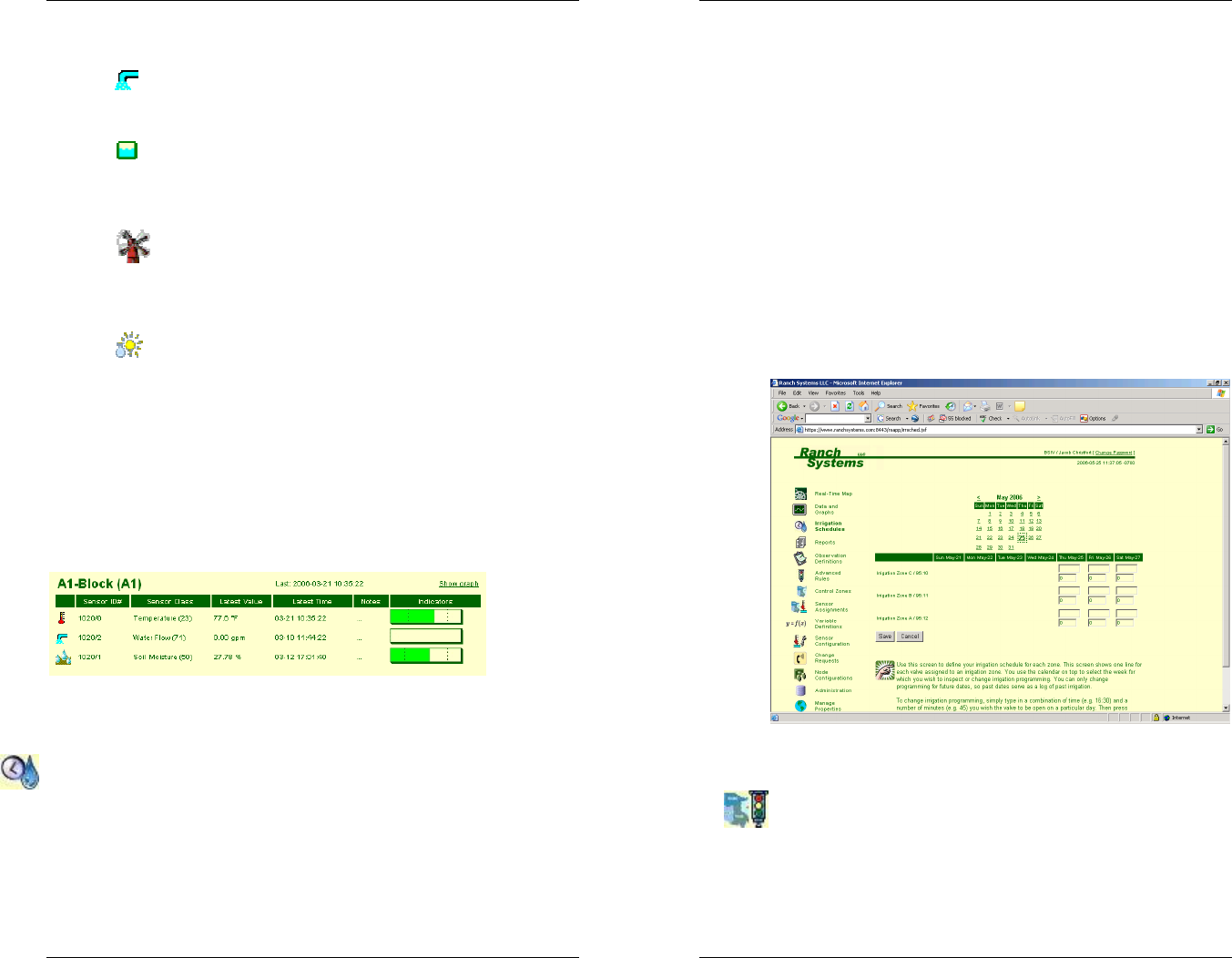
37
• Water Flow – This icon represents a sensor
that measures water flow in gallons per minute.
• Water Level – This icon represents a
sensor that measures the water level of a tank in
feet.
• Wind Speed – This icon represents a
sensor that measures the wind speed in miles
per hour.
• Relative Humidity – This icon represents a
sensor that measures the relative humidity as a
percentage.
Your sensors must be organized into control zones (see
the control zones segment later in this chapter) for
viewing within the data and graphs menu. The screen
below is an example of a control zone that has a
temperature sensor, a water flow sensor, and a soil
moisture sensor.
In order to display a graph of a specific control zone,
simply click the “show graph” link.
Irrigation Schedules - Use this screen to define your
irrigation schedule for each zone. This screen shows
one line for each valve assigned to an irrigation zone.
You use the calendar on top to select the week for which
you wish to inspect or change irrigation programming.
RanchMaster System Manual
38
You can only change programming for future dates, so
past dates serve as a log of past irrigation.
To change irrigation programming, simply type in a
combination of time (e.g. 16:30) and a number of
minutes (e.g. 45) you wish the valve to be open on a
particular day. Then press save, and the schedule is
changed.
WARNING: As soon as changes are made to this
schedule, they are automatically remember by the
RanchMaster system and will be executed accordingly.
So be careful to delete any “experimentation data” you
may enter to get familiar with the system.
Advanced Rules - Use this screen to define the rules
you wish the RanchMaster system to follow for
monitoring and controlling within your zones. You need
to assign sensors to your zones before defining your
rules (See Sensor Assignments above).

39
Each rule uses one or more variables (see below) to
define a condition that the system will regularly evaluate.
When the condition is met, the action associated with the
rule will be executed automatically.
You can use the following variables to define conditions:
ATP,LTP,HTP Average, lowest and highest
temperature in zone (Fahrenheit)
ASM,LSM,HSM Average, lowest and highest soil
moisture in zone (%)
AWL,LWL,HWL Average, lowest and highest water
level in zone (feet)
AFL,LFL,HFL Average, lowest and highest water flow
in zone (GPM)
AHM,LHM,HHM Average, lowest and highest relative air
humidity in zone (%)
AVL,LVL,HVL Average, lowest and highest valve
status in zone (0=closed, 1=open)
ABV,LBV,HBV Average, lowest and highest base
station battery voltage in zone (volts)
ANV,LNV,HNV Average, lowest and highest sensor
node battery voltage in zone (volts)
TOD
Current time of day as a decimal 24 hr
number. E.g. when it is 7.30pm this
variable will be 19.30
DOW Day of week as a number, 1-7.
1=Sunday
DOM Day of month as a number, 1-31
MON Month as a number, 1-12
Example formula: (ASM<15 and (TOD>19.30 or
TOD<9.00)) or (ASM<10)
RanchMaster System Manual
40
The "hours before re-arming" is the time in which the
rule will be de-activated after the condition is first met
and action is performed. This option controls how often
the rule will be resent: if the condition is still met after
this amount of time, the action will be executed again.
WARNING! As soon as you start adding rules, the
RanchMaster system will start acting on them, so be
sure the rules are really what you want. It is a good idea
to watch the dashboard frequently after establishing
and/or changing rules, in order to validate that
everything works as you intended.
Control Zones - Use this screen to create new control
zones or to delete existing zones. Control zones are the
fundamental way that you group sensors and valves that
are deployed in the same area. Typically a control zone
will be the same as a vineyard block. After creating a
new zone in this screen, use the separate icon on the
left toolbar to assign sensors to the zone.
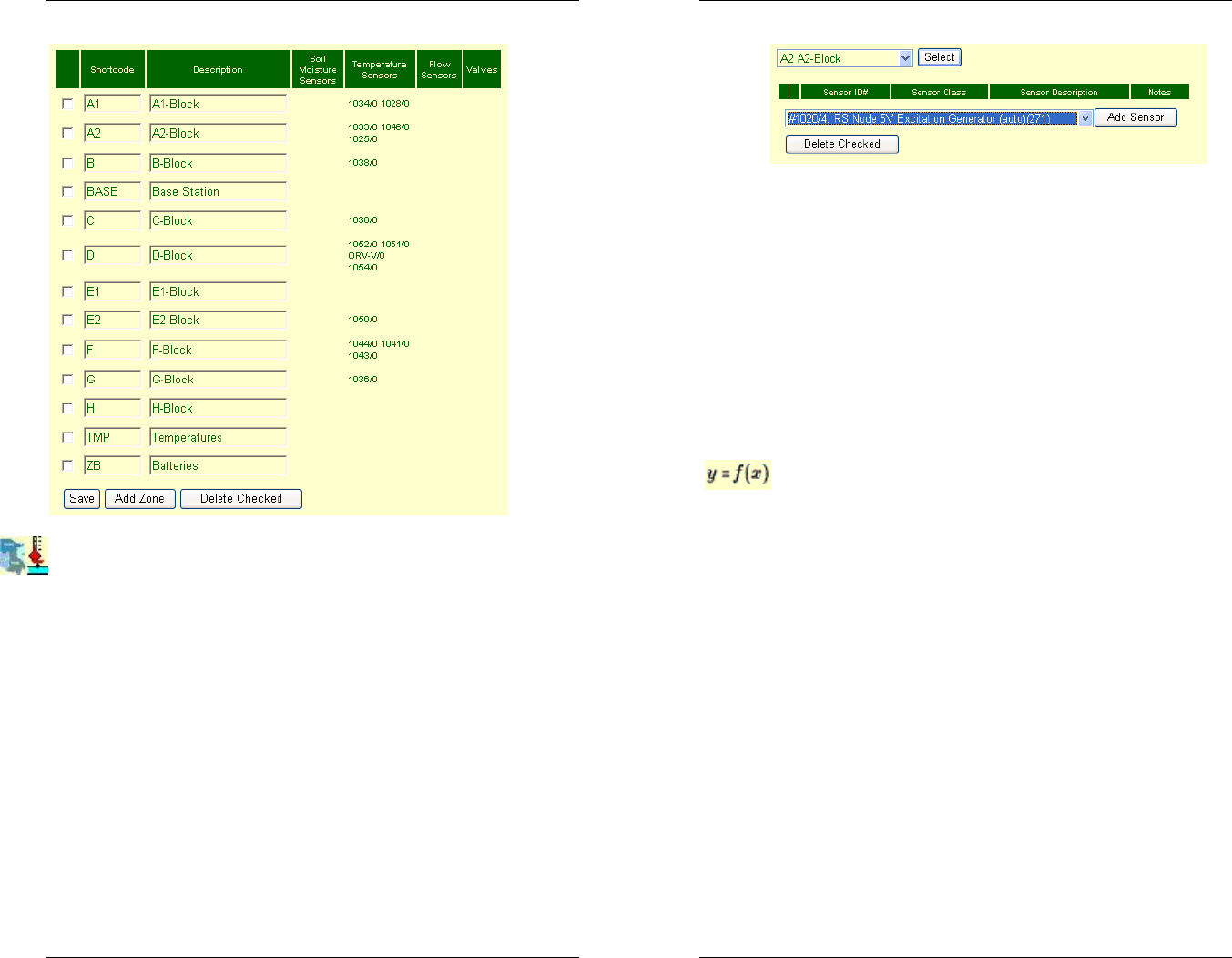
41
Sensor Assignments - Use this screen to assign
sensors and valves to control zones. To do this correctly,
you must first make note of the specific sensors placed
in the zone. Each sensor is identified by two numbers:
the RSUID (ie. Serial#) of the sensor node or base
station (e.g. #1003), and the port number between 0 and
13 where the sensor is connected. Both of these
numbers are printed on the boxes. However, it is
important to note that some port numbers refer to the
internal port, such as the voltage sensor sensing the
internal battery level. So for instance a soil moisture
sensor inserted into port 1 on node #1003 would be
called "1003:1", while the internal battery sensor of the
same node would be "1003:8".
RanchMaster System Manual
42
To add a sensor to a zone, you must first select the zone
you wish to associate the sensor with. Using the pull
down menu on the top, find your desired zone, and hit
the “Select” button.
Next you must assign the sensor to that zone. Using the
pull down menu on the bottom, find the sensor that you
want added to the zone and hit the “Add Sensor” button.
In order to delete a sensor from a zone, select the zone,
then check the box next to the sensor you wish to
remove and hit the “Delete Checked” button.
Variable Definitions - This page lets you create and
edit user-defined variables. Variables are a series of
data over time, much like sensors, but are calculated by
the RanchMaster system at fixed minute intervals based
on formulas that you specify. These variables are stored
and plotted in the system next to sensor data, and can
be viewed and plotted similarly. Variables can also be
freely used when defining control rules.
Variable data is automatically generated by the system
at certain intervals, and is specified for each variable in
minutes. You can also specify the date interval to
generate data, as you will often want the variables to be
generated for previous data, as well.
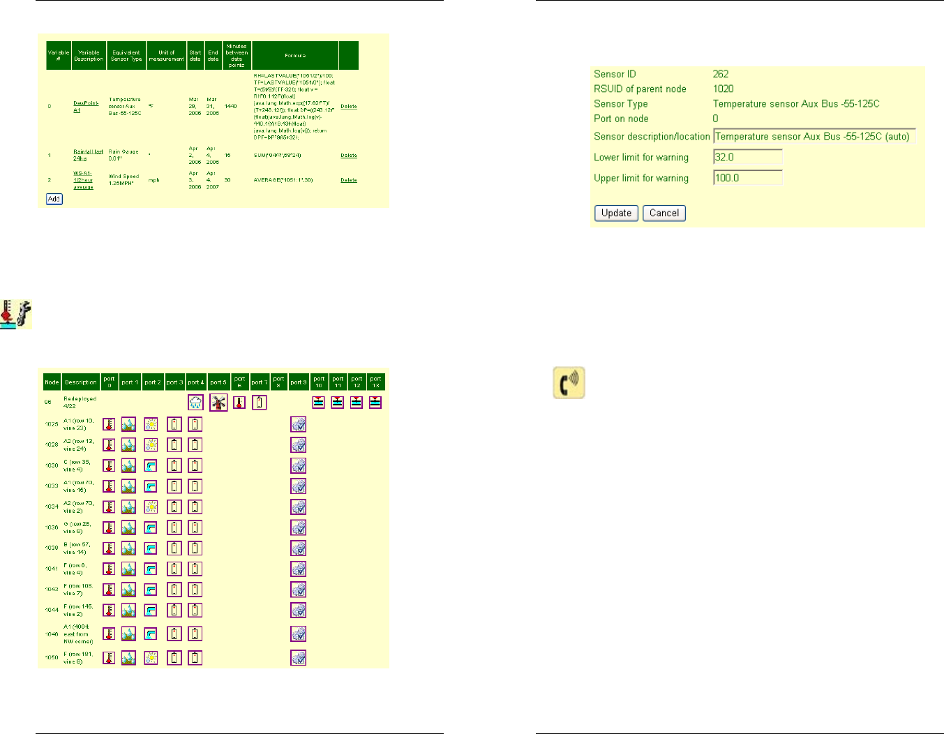
43
This picture shows some examples of variable
definitions. For assistance creating advanced variables,
please contact Ranch Systems support.
Sensor Configuration - The screen provides an
overview of all your RanchMaster system sensor nodes
and the attached sensors.
RanchMaster System Manual
44
Click on the sensor icon to see details for each sensor.
Most of the information in the sensor field cannot be
changed because it reflects the physical connection and
“wiring” of the sensor. However, you can modify the
description and the value limits to trigger warning emails
as well as the yellow/red color coding in various screens.
Change Requests - Use this form to submit service
requests to Ranch Systems support, service and
development, as well as to check the status of ongoing
requests, provide more information, etc. Make sure to fill
out all of the fields and be as specific as possible as to
the nature of your request or problem
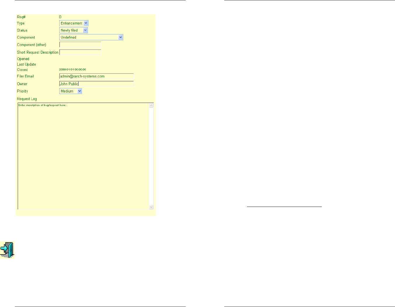
45
Simply click the “Add” link and then fill out the necessary
fields to report the problem.
Log Out – Clicking on this link will log you out of your
account.
RanchMaster System Manual
46
5.3 Text Messaging Control (aka SMS)
The RanchMaster system can be queried as well as
controlled in real-time using most of the commonly
available cellular phones.
Commands are sent to the base station by using SMS
text messages from a cellular phone. Once received,
the base station will reply to these messages. The
effective result is that you will be able to ‘chat’ with your
RanchMaster system.
The following is a list of SMS commands that the base
station will accept, and the resulting actions produced by
these commands. In order to send a command, simply
enter in the command as it is listed below, and send it to
the GSM phone number of your base station, which you
can find in the Configuration menu. Once the base
station receives the command, it will process the
information requested and send an SMS message back
to your phone.
Note, that while the commands are known by long
names, such as sensor or memory, you will almost
always want to use the shorter versions, such as s and
m, because of the limited keyboards on most phones.
Commonly Used Commands
• sensor or s – sensor data – this is the command
you will likely be using the most. There are several
distinct format options:
os – this queries for the nodes known to this
base station, including the base station itself.
os <RSUID> - this queries for all the sensors
attached to a particular node known to the
base station (Example: s 1098).

47
os <type> - this queries for all sensors of a
particular type across all nodes known to
this base station. The types are the same
used in the sensor status menu of the base
stations (Example: s FL):
oFL = Water Flow
oHM = Humidity
oSM = Soil Moisture
oTP = Temperature
oWS = Wind Speed
o3V = Internal Lithium Batter (ranges
from 3-3.5V)
os <RSUID> <port#> - queries the details of
a single, specific sensor identified by node
number and port (Example: s 1098 2).
• batt – Display the current battery charge level
• relay or r – Read or switch relay status. Command
is followed by a number from 1 to 4 and then
optionally by status ON or OFF. There are two
format options:
or <#> – query current status of relay/valve.
Example: r 1
or <#> <on/off> – turn relay/valve on or off
(Example: r 1 on).
• time – Show current base station time
• timeset – Set base station system time YYYY-MM-
DD HH:MM:SS. HH is 24 hours. WARNING:
causes system reset
• sync – Request out-of-cycle sync with server
• valve or v – Synonym for relay
RanchMaster System Manual
48
• memory or m - queries the current memory status
of the base stations.
These SMS commands can only be sent one at a
time. To continue sending SMS commands to the
same base station, you can simply use the reply
option after each SMS reply you receive. It is
important to note that due to the wireless nature of
SMS messaging, SMS messages may occasionally
be lost, so you should not assume that the base
station has received a command before you receive
an explicit reply.

49
Chapter 6 – Troubleshooting
6.1 Trouble Shooting Overview
• How do I change my login name and
password? Please contact Ranch Systems
support.
• What does it mean if a sensor has a red box
around it on the real-time map? A red box
indicates that the current value for that sensor is
outside of limits defined in sensor configurations.
• How do I change the limits for my sensor
values? To change limits, go to the Sensor
Configuration icon and click on the sensor that you
wish to change. You can set minimum and
maximum limit values in that field.
• What does it mean if I get a “Zone not defined”
message when I click on the Real-Time map? In
this case the zone mnemonic code which is
embedded in the map is not found as a valid
defined sensor zone. You can see the code
embedded in the map in the bottom window bar of
your browser when you move the mouse over the
field. Make sure that you have defined the
corresponding zones.
• How do I zoom in and out on graphs? You can
zoom into the graph either by clicking on a specific
data point, or by clicking on any vertical time band
RanchMaster System Manual
50
on the graph. You can also use the “Zoom”
function to navigate the graph. The “Zoom”
function allows you to view larger or smaller
amounts of data where the degree of zoom is
based on a multiplier factor. A factor of “1” will
keep the chart the same. A factor of “2”, will
double the zoom of the graph (i.e. from 20 hours to
10 hours). A factor of “3”, will triple the zoom, etc.
To zoom back out, just use negative numbers.
The “Zoom Left” and “Zoom Right” buttons will shift
the chart to the left or the right slightly (in terms of
date) with a little overlap.
• How do I change which sensors are in which
zones? You use the sensor assignment screen.
Note that the same sensor can be assigned to
multiple zones, which is helpful if you want to use,
say, a single humidity sensor as the proxy for
humidity in a number of zones.
• How do I know if I’ve used the correct syntax
for Advanced Rules? The system shows a status
field in the rules list, which tells you if the
conditions of the rule are currently met or not. If the
rule syntax is wrong, it will display “syntax error”.
• I changed the start date for my graph to an
earlier month but it’s not showing up – why?
The likely reason for data not appearing in early
months is that data wasn’t recorded at that time.
The graphs only generate lines where data has
been logged. If you request a graph for a period of
time that has no data, the graph will display a
simplified version that omits the portions without
any data (for example: if I request a graph for the
months of February and March, but my sensors
were installed in March, the resulting graph will
only display the period in March where data was
received).

51
• What is the difference between the signal
strength in the menu and the signal strength in
the top right corner? The number in the top right
corner stands for the first digit of the actual
percentage received. For example if the signal is
being received at 65%, the number in the top right
hand corner would be a 6.
• In Signal Strength, how can a signal be at -3%,
and what does the error rate mean? This occurs
when there is no signal and the modem is
searching.
• What reports are available to me? If you go to
the reports tab, you will see the standard reports
produced every night by the server. These are
produced in PDF format and will print as complete
‘books’ of reports and graphs. Some people find it
helpful to bind these regularly as a paper reference.
• What would I use Variable Definitions for?
Variable Definitions are useful if there is a value
that you want to track, like a sensor value, that is
not directly measured, and that can be derived
using other known sensor values. Dew point and
Gallons/Minute/Vine are two examples.
Chapter 7 – Customer Service
7.1 Customer Service
RanchMaster System Manual
52
The Ranch Systems office is open Monday through
Friday from 9am-5pm Pacific Standard Time. Operators
and Technicians are available to help you during these
times. Please consult your Ranch Systems manual
before calling to help specify the problem. Remember
that you can also log a problem online in the “Change
Requests” menu.
7.2 Contact Information
A Ranch Systems technician can be reached by calling
the Ranch Systems office at (415)-558 8044.

53
Glossary
Technical Terms
In this manual we will frequently use some technical
terms that should be explained here in a few words:
Base Station
This is the primary sending and receiving site in a
telecommunications facility network. In Ranch
Systems case, base stations are three-way wireless
units capable of communicating simultaneously on
three networks: 1. GSM cellular networks, 2. WiFi
networks following the 802.11B standard, 3. The
Ranch Systems proprietary VHF radio protocol
optimized for Ranch area networks
Cellular
The term cellular refers to circuit-switched voice
telephone communications via radio channels. The
service area is divided into many cells and in each there
is a base station handling the communications in that
particular cell. Ranch Systems uses cellular for base
stations to communicate with the central server.
GSM
This stands for “Global System for Mobile
communications”, the most widely used digital mobile
phone system and the de facto wireless telephone
standard in Europe. It was originally defined as a pan-
European open standard for a digital cellular telephone
network to support voice, data, text messaging and
cross-border roaming. GSM is now one of the world's
main 2G digital wireless standards. Implemented on 800,
900, 1800 and 1900 MHz frequency bands. The two
RanchMaster System Manual
54
components of GSM that is utilized by Ranch Systems
are SMS and GPRS.
GPRS
General Packet Radio Service: a radio technology for
GSM networks that adds packet-switching protocols,
shorter set-up time for ISP connections, and offer the
possibility to charge by amount of data sent rather than
connect time. GPRS promises to support flexible data
transmission rates typically up to 20 or 30 Kbps (with a
theoretical maximum of 171.2 Kbps), as well as
continuous connection to the network. Ranch Systems
uses the GPRS for data transfer between the base
station and the Ranch Systems server
IP Address
Each machine connected to the Internet has an address
known as an Internet Protocol address (IP address). The
IP address takes the form of four numbers separated by
dots, for example: 123.45.67.890.
LCD
This stands for “Liquid Crystal Display”. The screen of
the base station is an LCD display.
Node
A wireless sensor monitoring device that monitors
sensor data and uses sophisticated control signals to
keep base station abreast of sensor status. All of the
sensors in the RanchMaster system are attached to
nodes, which communicates status of those sensors to a
base station.
RSRF
This stands for “Ranch Systems Radio Frequency”. It is
a Ranch Systems proprietary wireless protocol in the
UHF band, optimized for ranch applications.
RSUID
Ranch Systems Unit ID.

55
This is simply a number that used to identify a Ranch
Systems sensor node or base station, and is equivalent
to a VIN number. You will find it printed on the front of
all sensor nodes.
Sensor
A device that responds to a stimulus, such as heat,
humidity or wind, and generates a signal that can be
measured or interpreted. Examples from the
RanchMaster system is soil moisture sensors, flow
sensors etc.
SMS
Short Message Service: available on digital GSM
networks allowing text messages of up to 160 characters
to be sent and received via the network operator's
message center to your mobile phone, or from the
Internet, using a so-called "SMS gateway" website. If the
phone is powered off or out of range, messages are
stored in the network and are delivered at the next
opportunity. Ranch Systems uses SMS for three
purposes: 1. to communicate urgent requests from the
internet application to base stations and sensor nodes, 2.
for users to communicate directly with the base stations,
3. to send SMS alerts to users based on rules and
conditions regarding the entire system.
Valve
A device fitted to a pipeline or orifice in which the closure
member is either rotated or moved transversely or
longitudinally in the waterway so as to control or stop the
flow. Ranch Systems supports three types of valves:
1.standard solenoid controlled irrigation valves power by
AC voltage, 2. standard solenoid controlled irrigation
valves switched by reverse polarity DC voltage, 3.
motorized shut off ball valves which can be used for
situations where there is little or no water pressure (as
opposed to standard irrigation valves).
WiFi
RanchMaster System Manual
56
The term WiFi, is short for ‘wireless fidelity’. A term for
certain types of wireless local area networks (WLAN)
that use specifications conforming to IEEE 802.11b. WiFi
has gained acceptance in many environments as an
alternative to a wired LAN. Many airports, hotels, and
other services offer public access to WiFi networks so
people can log onto the Internet and receive emails on
the move. Ranch Systems uses WiFi in order to
synchronize multiple base stations deployed on the
same property.
Zones
Groupings of sensors with a specific interdependency,
for example sensors and valves deployed in the same
irrigation vineyard block).

57
Contact Information:
Phone: 415-558-8044
Fax: 707-982-7078
Email: info@ranch-systems.com
Web: www.ranch-systems.com
555 De Haro Street
San Francisco, CA 94107
U.S A.