RapidWave RWIRL54BR1 High Rate Point-to-Point Wireless Bridge User Manual revised1 1
RapidWave Inc. High Rate Point-to-Point Wireless Bridge revised1 1
Contents
User Manual
1
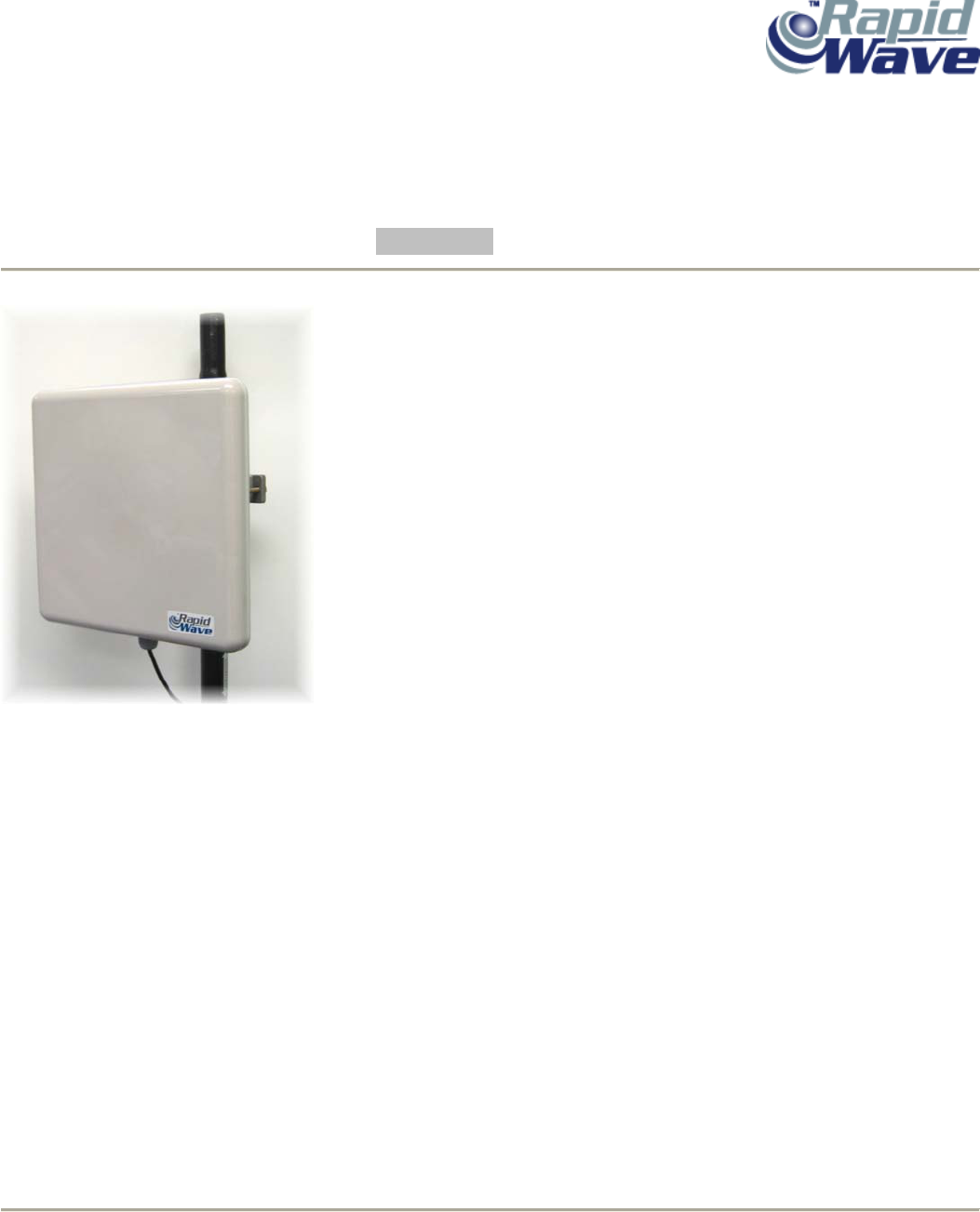
DRAFT 1.1 RapidLink 54 Wireless Point-to-Point Bridge
Installation Guide/Users Manual

RapidLink 54 Wireless Bridge
2 Installation Guide
Rev. 0.9 06-08-04
RapidLink is a trademark of RapidWave, Inc. Other trademarks or brand names mentioned herein are trademarks or
registered trademarks of their respective companies.
RapidWave, Inc.
6296 A San Ignacio Ave.
San Jose, CA 95119
Telephone: (408) 363-5984
Fax: (408) 363-5972
URL: http://www.rapidwaveinc.com
Any changes or modifications not expressly approved by the party responsible for compliance could void the user's
authority to operate the equipment.
Copyright © RapidWave, Inc. – All Rights Reserved
No part of this document may be copied or reproduced in any form or by any means without the prior written consent
of RapidWave, Inc.
RapidWave makes no warranties with respect to this documentation and disclaims any implied warranties of
merchantability, quality, or fitness for any particular purpose. The information in this document is subject to change
without notice. RapidWave reserves the right to make revisions to this publication without obligation to notify any
person or entity of any such changes.

RapidLink 54 Wireless Bridge
3 Installation Guide
Table of Contents:
1. For your safety...........................................................................................…..4
2. Components...........................……………………………...........................…...5
3. Installation................................……………………………….......……………...5
3.1 Connecting the Outdoor Units……………………………………..…….5
3.2 Connecting the Indoor Units (Power-over-Ethernet Injectors)………..8
4. Basic Configuration……………………………………………………………….11
4.1 Overview of the RapidLink 54 Web Interface…………………………11
4.2 Setting Basic Network Parameters…………………………………….11
4.3 Establishing a Wireless Link……………………………………………12
4.4 Aligning the Antennas………………………………………………...…14
5. Advanced Configuration Options and Tools……………………………………16
5.1 Advanced Page…………………………………………………………..16
5.2 Security………………………………………………………………..…..22
5.3 Antenna Alignment……………………………………………………….24
5.4 Firmware Upgrade………………………………………………………..24
6. Notes………………………………………………………………………………..25
7. Warranty……………………………………………………………………………26
__________________________________________________________________________
RapidLink 54 Wireless Bridge
4 Installation Guide
Section 1: For Your Safety
WARNING
Use extreme care when installing equipment or working near power lines.
CAUTION
When the unit is in operation, avoid standing directly in
front of the antenna. Strong RF fields are present when
the transmitter is on.
The antenna used for this transmitter must be installed to provide a
separation distance of at least 150 cm from all persons.
This Point-to-Point device and its antenna(s) must not be co-located or
operating in conjunction with any other antenna or transmitter.
This equipment has been tested and found to comply with the limits for
a Class A digital device, pursuant to part 15 of the FCC Rules. These
limits are designed to provide reasonable protection against harmful
interference when the equipment is operated in a commercial
environment. This equipment generates, uses, and can radiate radio
frequency energy and, if not installed and used in accordance with the
instruction manual, may cause harmful interference to radio
communications. Operation of this equipment in a residential area is
likely to cause harmful interference in which case the user will be
required to correct the interference at his own expense.
RapidLink 54 Wireless Bridge
5 Installation Guide
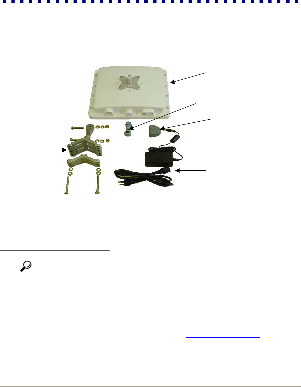
Model RL54-BR-23 comes with an integrated 23dBi gain antenna, installed from the manufacturer.
Model RL54-BR-26 comes with an integrated 26dBi gain antenna, installed from the manufacturer.
ALL OTHER COMPONENTS ARE IDENTICAL.
Section 2: Components
TWO SETS OF EACH SHOWN
Section 3: Installation
3.1 Connecting the Outdoor Units
NOTICE To meet regulatory restrictions, RapidWaves’external antenna bridge configuration and any
external antenna must be professional installed.
Step 1: Select optimal locations for the two outdoor units. Consider the following criteria to ensure maximum
performance and stability of your wireless connection:
Best signal path possible, ideally with visual line of sight
Fresnel zone clearance
The shortest distance possible between the Bridge
Less than 320 feet from either bridge to the indoor Power-Over-Ethernet adapter
Optimal transmission range (visit the online range calculator at http://www.rapidwaveinc.com)
Step 2: Set up your poles in the two locations you ascertained in step 1.
Mounting
Hardware
Bridge Radio Unit
Weatherproof
Wire Gland
Indoor Power-
Over-Ethernet
Adapter Base Unit
Indoor AC/DC
Power Adapter
RapidLink 54 Wireless Bridge
6 Installation Guide
Perform the following steps (3-4) for the Master Bridge first, and then repeat these steps for the Partner Bridge.
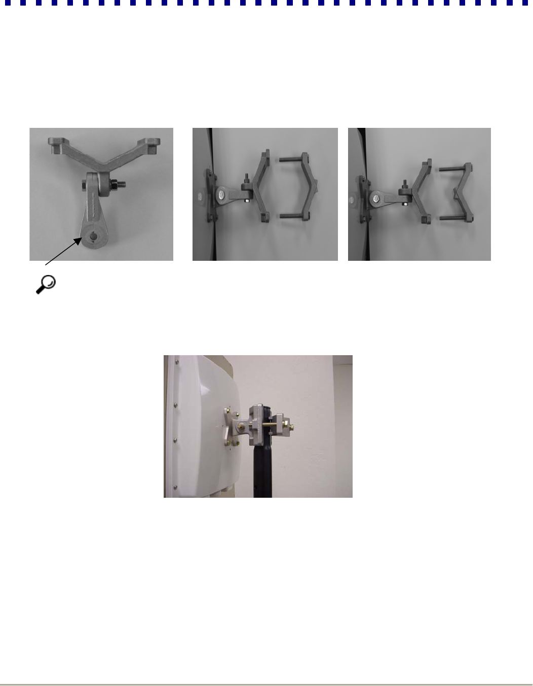
Step 3: Attach the outdoor units mounting brackets.
Tip Only use the supplied extension bracket if necessary, otherwise it is recommended to mount the antenna-
mounting bracket directly to the female pole-mounting bracket as depicted below. If the extension bracket is
required for appropriate installation, than it will also be necessary to remount the antenna bracket on the back of the
antenna, to maintain an upright and vertical position.
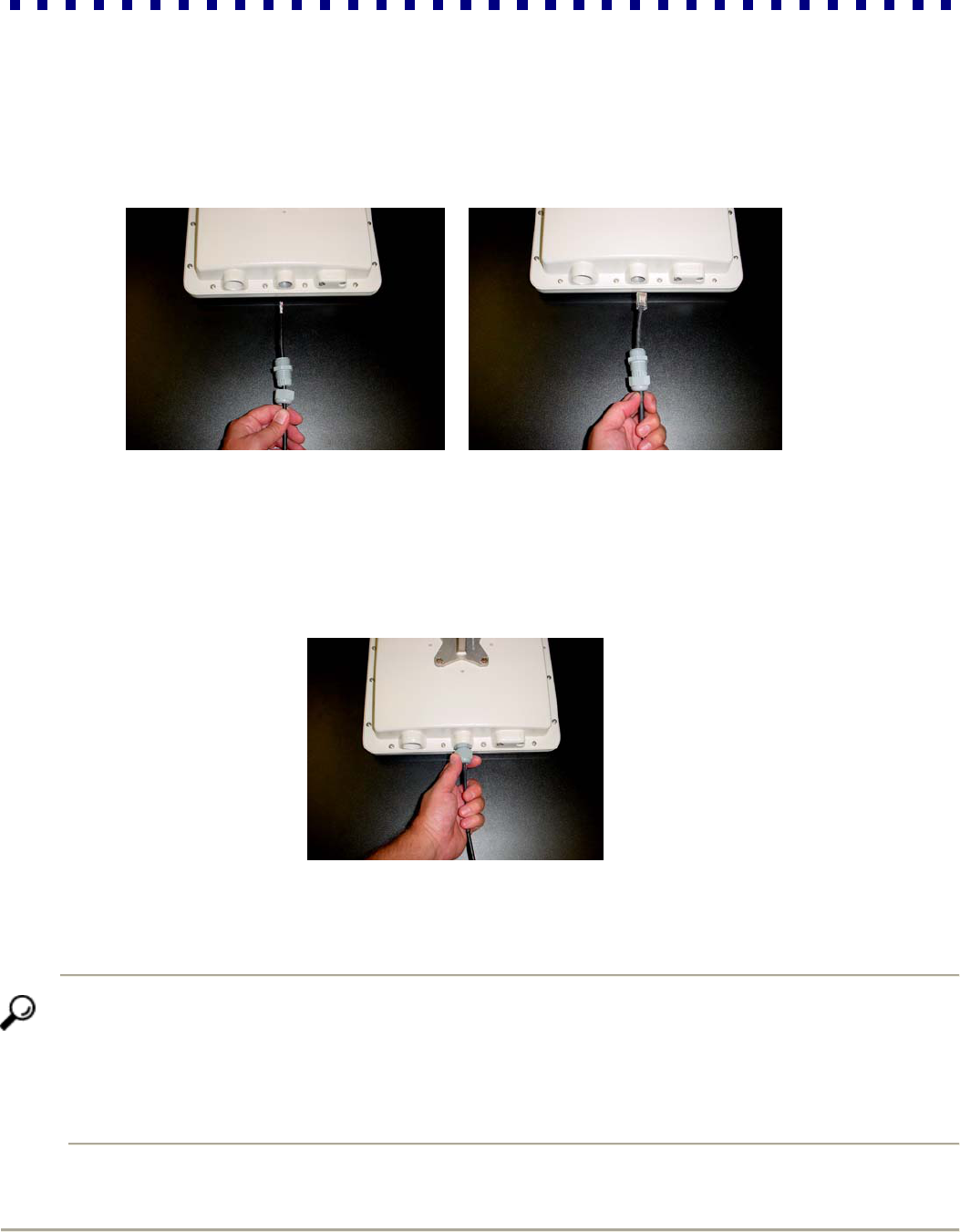
Step 4: Install “User Supplied” CAT5 Weatherized Ethernet straight-through cable.
------ Do not exceed 320 feet (100 Meters) of cable per link------
Step 6: Determine the appropriate routing length for your Ethernet cable and cut to length.
Step 7: Splice and crimp indoor mounting side of the CAT5 Ethernet Cable with an RJ-45 connector.
RapidLink 54 Wireless Bridge
7 Installation Guide
Step 8: The RL54 mounting side of the Ethernet cable must first be routed through the supplied weatherized wiring
gland, than spliced and crimped with a RJ-45 connector. It is Highly recommended that you test the
cable with an RJ-45 wiring tester before installing.
Step 9: Connect the RJ-45 to the female connecter located directly inside the enclosure, make sure the
connection is locked in place before tightening the gland.
Step 10: Tighten the gland to the enclosure and than tighten the compression nut around the Ethernet
Cable
Step 5: Mount the outdoor units to the poles you set in step 2
Tip After mounting the outdoor unit, loosen its pole mounting clamp just enough to maneuver the antenna vertically and
horizontally. Point the antenna toward the remote device. If you are close enough to see the remote location, visually align
the antenna toward the Partner Bridge location as accurately as possible. If you cannot see the remote location, use
binoculars, a telescope or laser pointer.
Do not completely tighten the screws immediately because you will later perfect the alignment with the RapidLink 54 antenna
alignment tool.
RapidLink 54 Wireless Bridge
8 Installation Guide
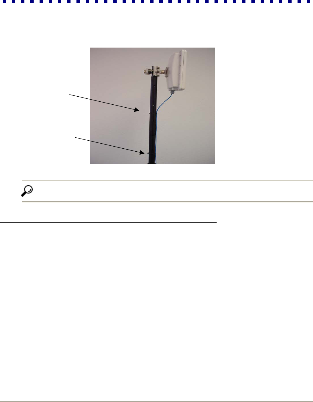
Step 6: Secure the outdoor unit’s Ethernet cable (that you attached to the bottom of the outdoor unit) along the length
of the pole using tie-wraps, run the cable toward the inside of the building.
Tip For best results, secure this cable to the pole at least every 10 feet with tie-wraps.
3.2 Connecting the Indoor Units (Power-over-Ethernet Injectors)
The indoor unit is the point at which the outdoor units connect with your indoor LAN. More specifically, the indoor unit
connects your wireless bridge to the network and transmits both data and power to the outdoor unit.
Perform the following steps (1-6) to connect the indoor unit of the Master Bridge first, and then repeat these steps for
the Partner Bridge.
Step 1: Place the indoor unit in an appropriate location that meets the following criteria:
The distance from the outdoor unit to the indoor Power-Over-Ethernet adapter must not exceed the length of
your Ethernet cable after attached to the bottom of the outdoor unit
The distance from the indoor unit to the Ethernet network backbone device (e.g., hub or switch) must not
exceed 320 ft (100 meters)
The distance from the indoor unit to an available AC outlet must not exceed the length of the supplied power
cable
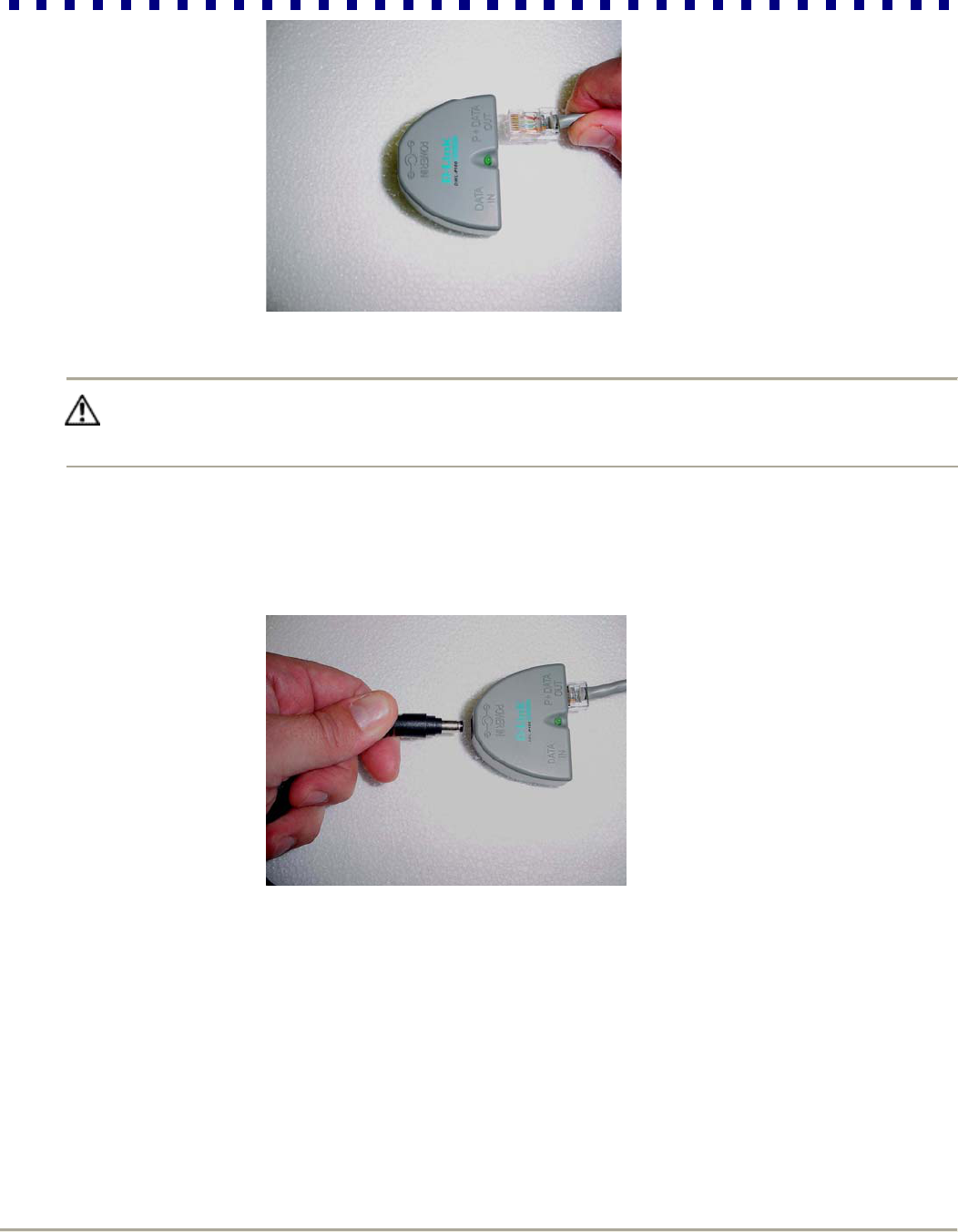
Step 2: Bring the Ethernet cable into to the wiring closet (where the indoor unit is located), and plug the RJ-45
connector into the combined Ethernet/power output port (P + Data Out) on the front panel of the indoor unit.
RapidLink 54 Wireless Bridge
9 Installation Guide
Caution Connecting any device other than the outdoor unit to the indoor unit may cause permanent hardware
damage. Do not confuse the RJ-45 connector of the outdoor unit’s with that of the Ethernet cable connected to
your backbone device.
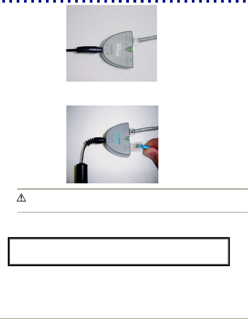
Step 3: Connect one end of the brick style power adapter cable to the power jack (Power In) on the rear panel of the
indoor unit, and plug the other end of the power cable into the AC wall outlet.
Step 4: Check the front panel of the indoor unit to make certain that the power LED is on. If the power LED is not on,
confirm that the power cable is securely connected and that your power source is operational.
RapidLink 54 Wireless Bridge
10 Installation Guide
Step 5: Plug your Ethernet patch cable into the Ethernet input port (Data In) of the indoor unit and into the data port of
your backbone device.
Caution Do not confuse the Ethernet input port with the Ethernet/Power output port. To avoid permanent hardware
damage, make certain that you connect your backbone device to the Ethernet input port (not the Ethernet/Power
output port).
Step 6: Check the link LED on your backbone device to confirm that it is on.
Congratulations! At this point, you have completed all the hardware related steps necessary to
establish your point-to-point wireless link. However, your wireless link is not yet operational. The nex
t
section will describe basic software configuration and antenna alignment procedures necessary to
activate the wireless link.
RapidLink 54 Wireless Bridge
11 Installation Guide
Section 4: Basic Configuration
4.1 Overview of the RapidLink 54 Web Interface
All configuration parameters are accessible through an embedded web server interface called the Wireless Link
Manager (WLM). Using a web browser, you can easily log into the web server of the Master and Partner Bridge. From
this user-friendly interface, you can communicate with any RapidLink 54 unit and perform configuration, management
and trouble-shooting tasks.
4.2 Setting Basic Network Parameters
In this section, you will log into the RapidLink 54 WLM for the first time and identify your bridges. After performing
steps 1-9 for the Master Bridge, repeat these steps for the Partner Bridge.
Step 1: Load your web browser.
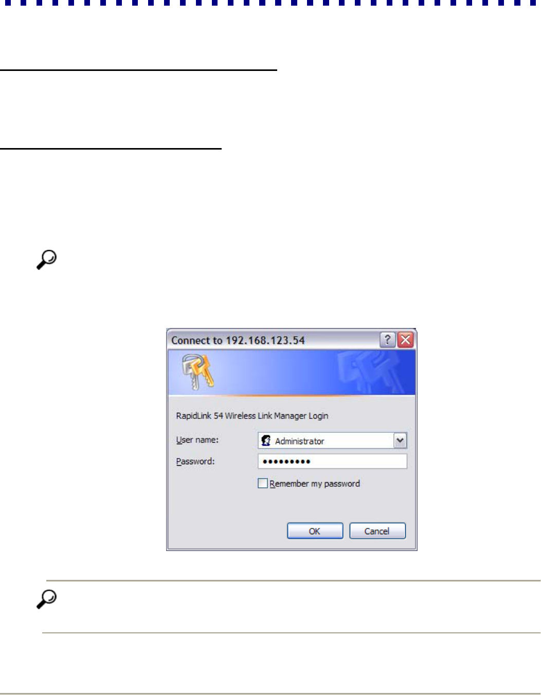
Step 2: Type the factory default IP address: 192.168.123.54 into the address field of your browser and press Enter.
This will load the RapidLink 54 WLM.
NOTICE When Setting up the Partner Bridge, type in IP address: 192.168.123.55
Step 3: Enter the default (Case Sensitive) Login: Administrator and Password: RapidLink when prompted and click
Enter.
Tip It is strongly recommended that you change the Password and Login as soon as you have completed the
basic configuration by clicking on the Security tab. See section 5.2 under Security for full details on changing
password.
RapidLink 54 Wireless Bridge
12 Installation Guide
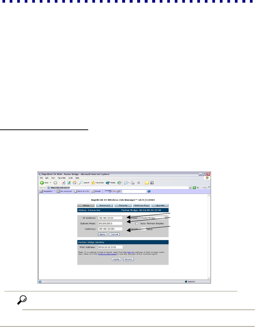
Now you will see the RapidWave 54 WLM. Along the top of the page, you will find five tabs that contain all the
configuration options available for RapidLink 54. These tabs are: Setup, Advanced, Security, Antenna Align and
Upgrade. You will use the Setup page to set network parameters and establish your wireless link. The other tabs will
be described in later sections.
Step 4: Enter a new IP Address for the Master Bridge (the IP address of each device must be unique) and write it
down for future reference.
Step 5: Enter a Subnet Mask (if different than the default value).
Step 6: Enter the current Gateway Address of the Master Bridge to which you are connected.
Step 7: Enter the Name of your Master Bridge.
Step 8: Click Apply.
Step 9: To put the changes into effect, click on Restart, a dialog box will appear, click OK. The bridge will then
restart.
4.3 Establishing a Wireless Link
The following steps will help you establish a wireless connection between the Master and Partner Bridge:
Step 1: Type the new IP address that you created in previous steps in the address field of your browser and press
Enter to load the web interface of the Master Bridge. Login with your user name and password. Before moving
on to the next step, make certain that the Setup page shows the new settings you initiated in the previous
section.
Tip Now that you have assigned the final IP address, it is a good time to bookmark your user interface for
easy access as you manage your wireless link.
RapidLink 54 Wireless Bridge
13 Installation Guide
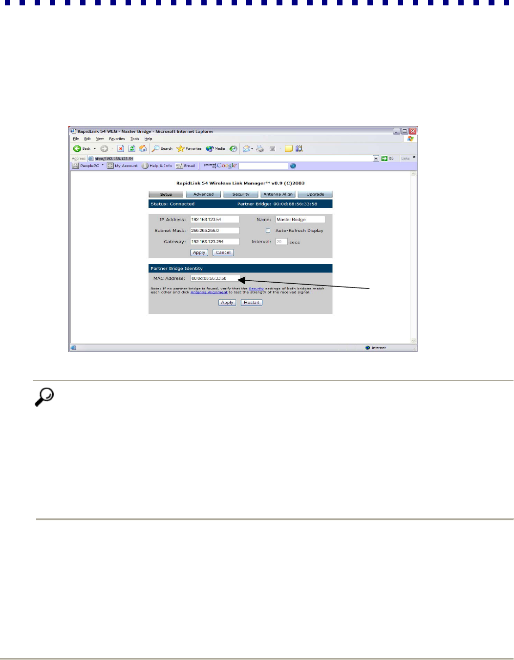
Step 2: The MAC address of the Partner Bridge is listed under Partner Bridge Identity. If the desired connection
partner is available, the two radios initiate the association process and establish a wireless link. After this link
is established, the correct status will be reported on the status bar of the web interface, and any association
requests by other stations will be blocked.
Tip You will not be able to connect if certain Master and Partner Bridge settings are not identical. By
factory default, the Master and Partner Bridge are configured to match. If you have changed any of the
following parameters: Transmit Mode, Data Rate, Channel, SSID, Encryption Mode and Active
Encryption Key, ensure that the configurations of both the Partner and Master Bridge are compatible. In
cases where the settings match
and Connect is still unsuccessful, ensure that:
The Partner Bridge is not out of transmission range
The antennas are in alignment
If any of these issues have caused the Connection process to fail, skip the rest of section 4.3 and solve
the issues by referring to the instructions corresponding to the issue. When you have solved the problem,
go back to step 2 and continue the steps in this section.
RapidLink 54 Wireless Bridge
14 Installation Guide
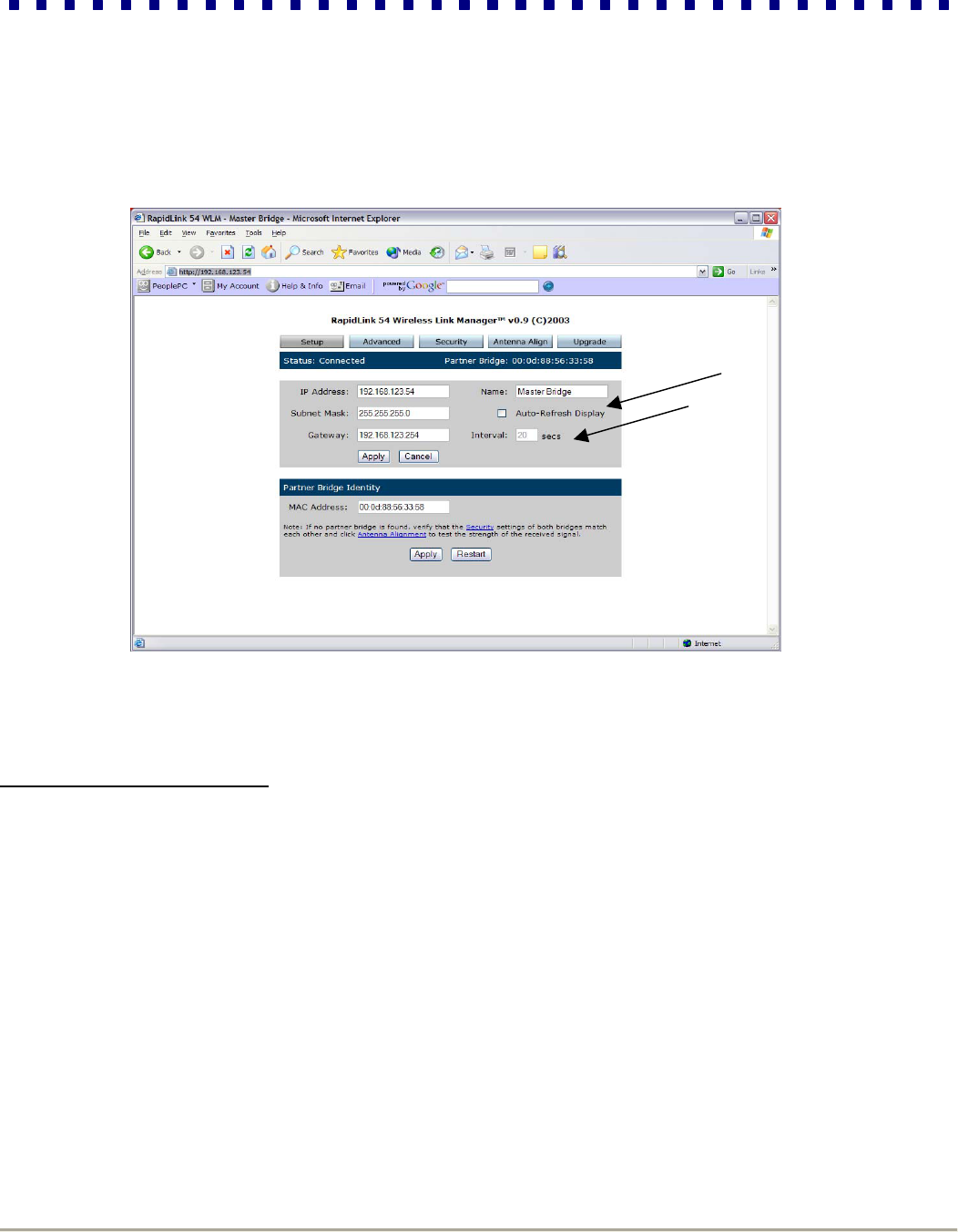
Step 3: You should now have an active link. In order to monitor your link status on an ongoing basis, enable the Auto-
Refresh Display option and specify the time Interval in which the screen updates the status information.
4.4 Aligning the Antennas
Now that you have activated the wireless link between the Master and Partner Bridge, you can adjust your antenna
alignment to maximize performance. Depending upon the characteristics of your antennas and the distance between
them, antenna alignment can be performed visually or you may opt to use more sophisticated tools and methods of
aiming such as telescopes or laser pointers. The WLM provides a tool designed to help you optimize antenna
alignment, ensuring the highest signal quality and stability possible. The longer the distance, the greater the need for
this tool. As you make physical adjustments to the antenna, the antenna alignment tool will show the resultant
transmission quality between the two devices in the form of signal strength and RSSI value. Follow the procedures
below for the Master Bridge, and then repeat these steps for the Partner Bridge:
Step 1: Take a laptop computer to the antenna location and load the RapidLink 54 user interface.
RapidLink 54 Wireless Bridge
15 Installation Guide
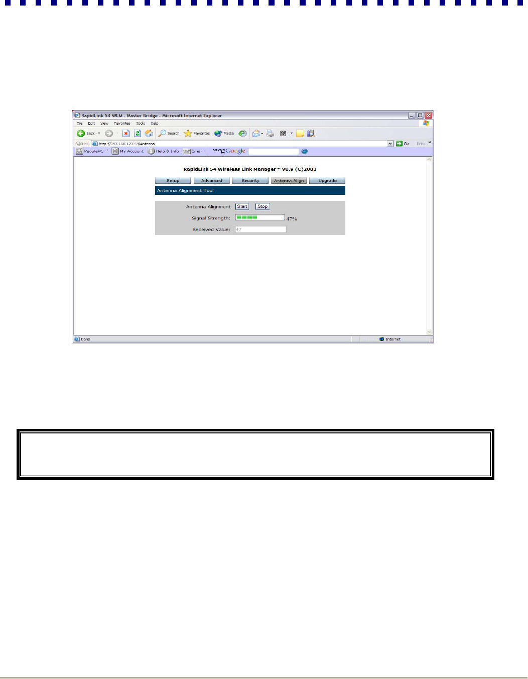
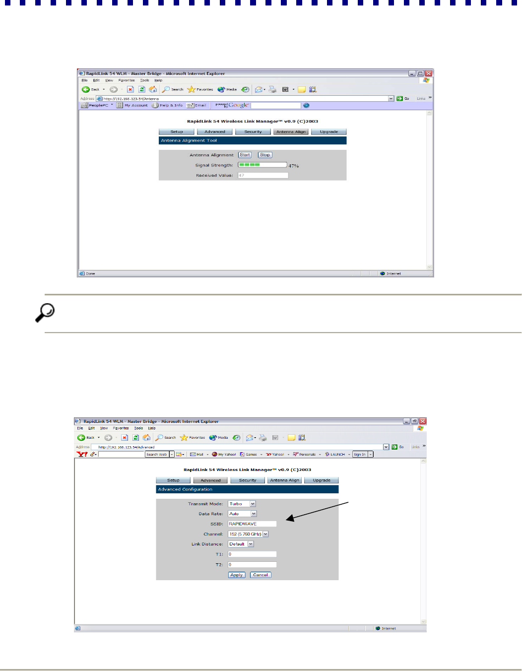
Step 2: Select the Antenna Align tab and click Start to enable the antenna alignment tool. The Signal Strength and
Received Value indicators will now show dynamically updated measurements until you click Stop.
Step 3: Monitor the Signal Strength indicator as you align the antenna vertically (if antennas are not on the same
elevation). When the signal quality reaches an acceptable level, tighten the screws.
Step 4: Repeat step 3 for horizontal alignment.
Congratulations! You have now completed all the steps to set up an operational wireless link. The
next section will describe the various configuration options and walk you through the process of
changing system settings to meet your specific requirements.
RapidLink 54 Wireless Bridge
16 Installation Guide
Section 5: Advanced Configuration Options and Tools
Now that you have established a functional link, you may wish to customize parameters according to your needs and
preferences. From radio-related parameters and security algorithms to diagnostic tools and firmware upgrade utilities,
the WLM offers numerous options that help you effectively manage the system and achieve the highest performance
possible. This section describes RapidLink 54’s advanced configuration options, which you can find in the following
categories:
▪Advanced ▪Security ▪Antenna Align ▪Upgrade
Accessing the advanced options is simple. From the RapidLink 54 WLM, simply click on the tab corresponding to the
category you need. The following sub-sections will explain how to configure each parameter within these categories.
Tip While the options differ, each page functions similarly. As you read the next subsections, keep in mind that
regardless of the page, any change you make can only go into effect if you click Apply. If you do not click Apply
before moving to the next page, your changes will be lost.
Also be advised that certain parameters in the Advanced and Security pages require you to restart the system in
order to take effect. In such cases, go back to the setup page and click on Restart. If you know that you will be
making more changes, you can complete all other changes, and restart the system later.
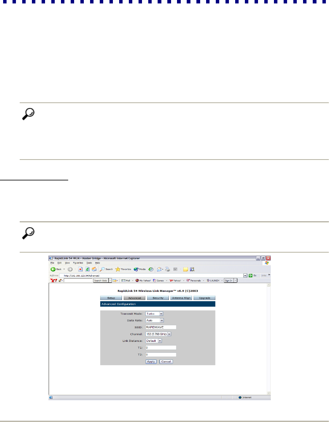
5.1 Advanced Page
This page allows you to control radio-related parameters, including Transmit Mode, Data Rate, SSID, Channel and
Link Distance. As mentioned in section 4.3, step 2, these parameters must be identical on both sides of the wireless
link. Therefore, any change on the Master Bridge should also be executed for the Partner Bridge. This sub-section
explains the options in each field of the Advanced page.
Tip Transmit Mode, Data Rate, and Channel settings are interdependent. Data Rate and Channel are always
updated according to the Transmit Mode setting. It is therefore recommended that you select the Transmit Mode
first and follow the instructions below in the order that they are presented.
RapidLink 54 Wireless Bridge
17 Installation Guide
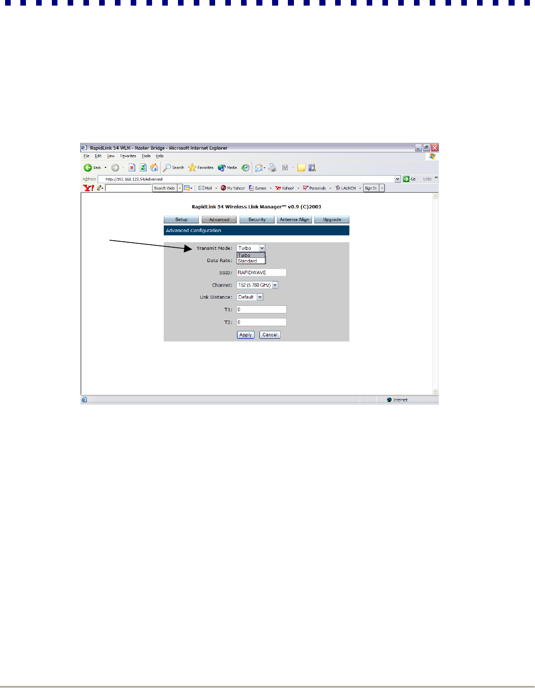
Set Transmit Mode:
Simply click the drop-down menu in the Transmit Mode field and select either Turbo or Standard Mode. Data Rate
and Channel options will then update according to the new setting.
RapidLink 54 Wireless Bridge
18 Installation Guide
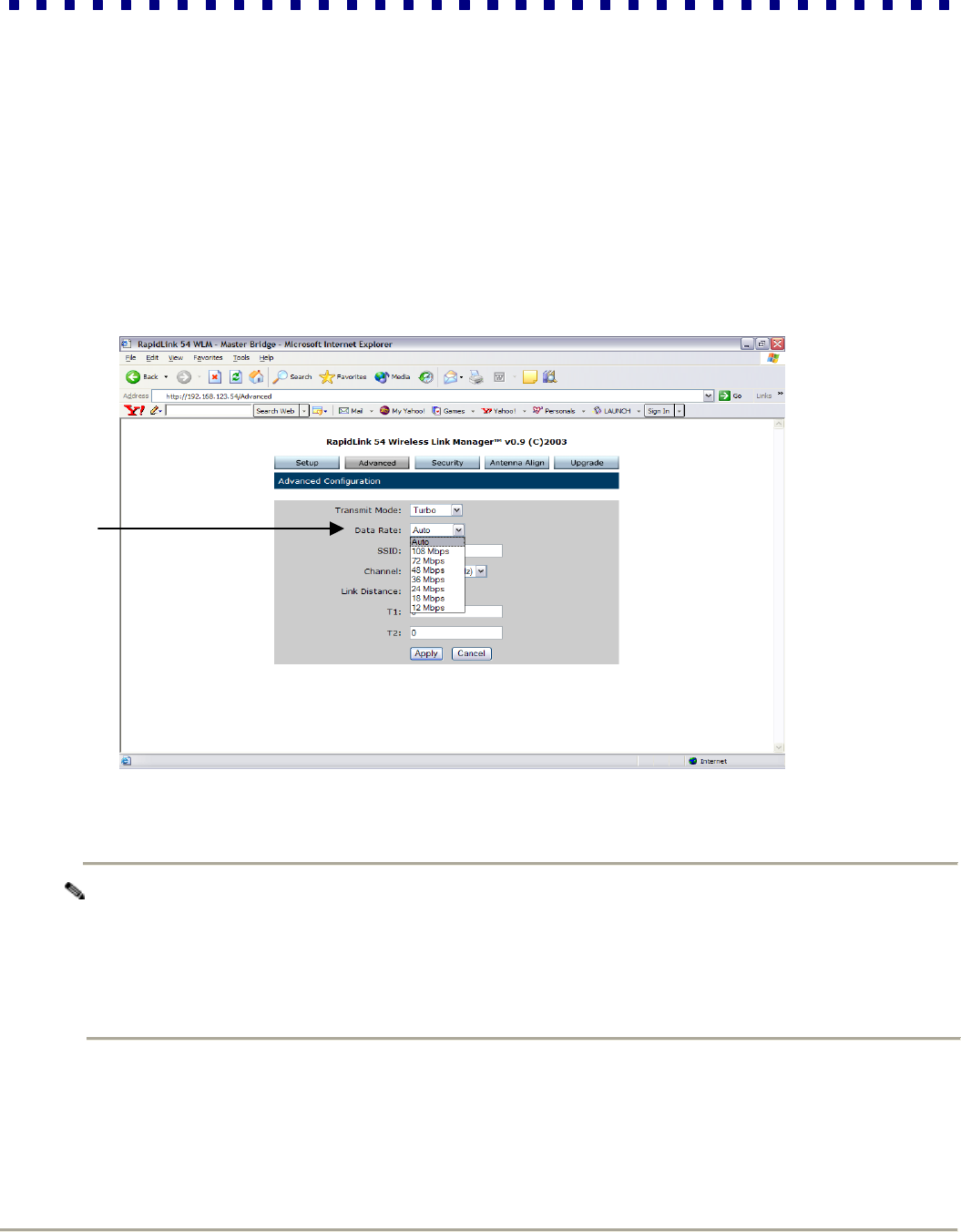
Set Data Rate:
RapidLink 54 supports several possible data rates ranging from 6 to 108 Mbps. The highest transmission rate is 108
Mbps, with automatic fallback rates that allow the unit to operate in the most efficient manner. By default, the system
automatically switches between these rates to maximize coverage. However, you may wish to select a fixed Data Rate
based on your specific objectives or needs.
Step 1: To adjust this parameter, click the drop-down menu in the Data Rate field and select the desired rate.
Note The default setting, Auto, is recommended.
Auto: When the Data Rate is set to Auto, the Master Bridge will follow an algorithm to determine the
highest bit rate possible for communication with its Partner Bridge.
Fixed Bit Rate: The Auto setting is disabled by selecting a specific bit rate to be used for the wireless link.
This would be appropriate when operating in a well-understood environment, and when full rate operation is
not possible. It is recommended that you start with the lowest bit rate.
RapidLink 54 Wireless Bridge
19 Installation Guide
Step 2: Click on Antenna Align to check signal strength. Be advised that different data rates have different
sensitivities, which impact range.
Tip Make certain that you still have a good signal. If the Received Value is not high enough, then scale
down the Data Rate.
Enter SSID:
The SSID is a service set identifier that uniquely describes your bridge pair. Always use the same SSID for both
bridges.
RapidLink 54 Wireless Bridge
20 Installation Guide
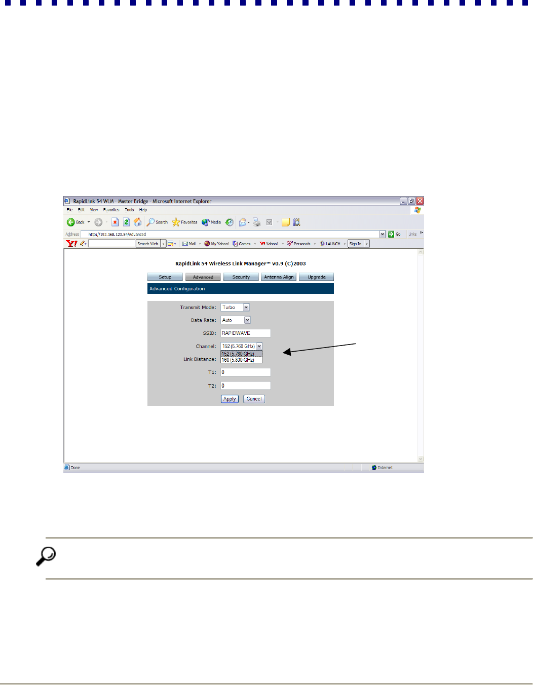
Set Channel:
Channels are used to set the center frequency used to transmit data over the wireless bridge link. You can avoid active
interference by switching channels if you suspect interferers operating on the same frequency. Available channels
shown in the drop-down menu are based on local regulatory requirements.
To set the Channel: Click the drop-down menu in the Channel field and select the desired frequency.
Five channels are available in Transmit Mode Standard
Two channels are available in Transmit Mode Turbo
Tip If active interference is not an issue, it is recommended that you choose the default
Channel (lowest frequency) in order to maximize range.
RapidLink 54 Wireless Bridge
21 Installation Guide
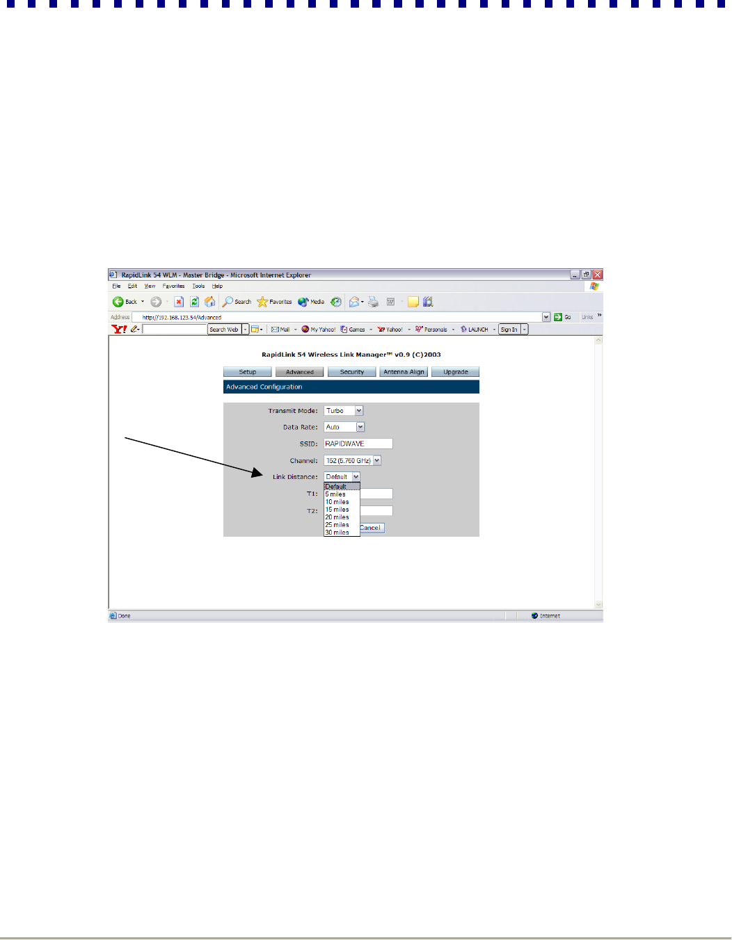
Set Link Distance:
Entering the correct Link Distance maximizes performance by ensuring that the system is ideally tuned to the
distance between the Master and Partner Bridge. You can change this anytime by clicking the drop-down Link
Distance menu and selecting the desired setting.
RapidLink 54 Wireless Bridge
22 Installation Guide
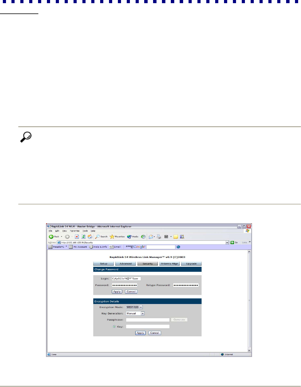
5.2 Security
This section describes the parameters available through the Security menu. RapidLink 54 provides two forms of
security, access control and privacy. Access control is achieved by MAC address authentication, which allows only
known devices to associate with the Master Bridge and establish a wireless connection (refer to section 4.3, step 2).
Another component of access control is the password protected user interface, which can be configured on the
Security page. Privacy is accomplished by enabling encryption that prevents rogue stations or wireless sniffers from
decoding any captured data. RapidLink 54 provides 128-bit WEP encryption option on the Security page.
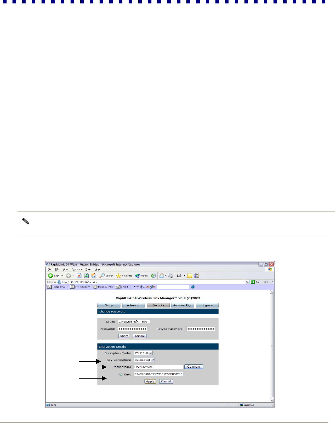
Changing your Password
We recommend that you change your Login and Password from the factory default setting to authenticate the identity
of the RapidLink 54 administrator and ensure that no unauthorized users gain access to the WLM.
To change your Login and Password, type a new Login name (16 characters maximum). Next, enter a new
Password, (16 characters maximum) and enter it again to confirm.
Tip Create passwords according to the following guidelines:
Do Not
Share passwords with unauthorized users
Use personal information easily obtained, such as your actual first or last name, system name, etc.
Use words commonly used as passwords
Use dictionary words or names
Do
Base passwords on non-dictionary words, combined with obscure character substitutions
Use the maximum number of characters
Change passwords regularly
RapidLink 54 Wireless Bridge
23 Installation Guide
Privacy
You can enhance link privacy by setting the Encryption Mode to WEP-128 and entering a valid encryption key. You
have the option of either creating keys manually or having the system generate a key for you automatically.
By default, the Encryption Mode is Off. If you wish to increase link privacy, perform the following steps for the Master
Bridge, then repeat these steps for the Partner Bridge.
Step 1: If you wish to enable encryption, select WEP-128.
Step 2: Click the Key Generation drop-down menu and select either Manual or Automated. If you select Manual,
you are required to manually enter each key as described below. If you prefer, you can select Automated, and
the system automatically generates four distinct keys based on a passphrase that you enter.
Step 3: Generate at least one valid encryption key. The steps are as follows:
If the Key Generation field is set to Manual, enter keys directly into the fields. Each key must be
composed of 32 hexadecimal characters in the range of A-F and 0-9.
If Key Generation is set to Automated, the Passphrase field and Generate button are enabled.
a. Type a Passphrase (no more than 32 characters) that you can easily memorize.
b. Click Generate, and a one-way hash algorithm will be applied to hash the Passphrase using the
specified character encoding and copy the results into the encryption key field.
Note The passphrase is not exchanged over the air. It is as secure as a manually generated key, but easier to
remember.
Step1
Step2
Step3
RapidLink 54 Wireless Bridge
24 Installation Guide
5.3 Antenna Alignment
The Antenna Align page is typically used for initial antenna alignment (see section 4.4 for details). However, you can
also use it as a tool to monitor the quality of the wireless link in real-time. This is especially helpful if you have made
any changes to the system. Click Start and the tool runs continuously until you click Stop. Once the antenna
alignment tool has started, you will see the Signal Strength and Received Value measurements updated in short
intervals.
5.4 Firmware Upgrade
Periodically, RapidWave, Inc. will release firmware updates that enhance various aspects of RapidLink 54. After
registering on http://www.rapidwaveinc.com, you will have access to all the firmware upgrades available. If you have
questions about upgrading your firmware, please contact RapidWave’s support team.
Caution Upgrading the firmware of RapidLink 54 may overwrite some of your configuration parameters. It is
therefore important to save a copy of your current settings before performing firmware upgrades so you can re-enter
your current settings at the end of the upgrade process. To document your current settings, access and print each of
the following screens: Setup, Advanced and Security. Make certain that you do this for both the Master and Partner
Bridge.
The steps involved in performing a firmware upgrade are as follows:
Step 1: Obtain firmware image from RapidWave and save it to a directory on your computer or network drive.
Step 2: Start an FTP Server on your computer. Configure an entry for the user name “rapidwave”, with the password
“rapidwave”. The home directory for the “rapidwave” user should be set to the directory where the firmware
image is stored.
Step 3: From the Master side browser interface select Upgrade.
Step 4: Specify your FTP Server address in the space provided.
Step 5: Click browse to open the Windows browse file dialog.
Step 6: Click Upgrade to upload the image to the Master Bridge.
Step 7: Click OK when you see the pop-up with a warning and OK/Cancel options.
Step 8: When you have successfully loaded the new firmware, the system must be restarted.
Step 9: Repeat steps 2-7 for the Partner Bridge.
Tip For greatest interoperability, upload the same firmware image or revision for the Master and Partner Bridge.
Make sure that the firmware revisions match on both sides.

RapidLink 54 Wireless Bridge
25 Installation Guide
Section 6: Notes
___________________________________________________________________________
___________________________________________________________________________
___________________________________________________________________________
___________________________________________________________________________
___________________________________________________________________________
___________________________________________________________________________
___________________________________________________________________________
___________________________________________________________________________
___________________________________________________________________________
___________________________________________________________________________
___________________________________________________________________________
___________________________________________________________________________
___________________________________________________________________________
___________________________________________________________________________
___________________________________________________________________________
___________________________________________________________________________
___________________________________________________________________________
___________________________________________________________________________
___________________________________________________________________________
___________________________________________________________________________
___________________________________________________________________________
___________________________________________________________________________
_____________________________

RapidLink 54 Wireless Bridge
26 Installation Guide
Section 7: Warranty
RapidWave - Limited Warranty
RapidWave Inc. warrants that hardware products will be free from material defects in materials and workmanship for the term of one
year from product shipment date. RapidWave Inc. warrants that software media will be free from material defects in materials and
workmanship for a period of one year from shipment date.
This Hardware Product warranty covers all RapidWave Inc. parts, accessories, and upgrades sold with your RapidWave Inc.
Hardware Product. Unless otherwise set forth, RapidWave Inc. accessories and upgrades purchased and added on to the
Hardware Product after the initial Hardware Product purchase assume the warranty deliverables and term of the system into which
they are installed.
Limitations
NEITHER PARTY WILL BE LIABLE FOR ANY INDIRECT, PUNITIVE, SPECIAL, INCIDENTAL, OR CONSEQUENTIAL DAMAGES IN
CONNECTION WITH OR ARISING OUT OF THIS WARRANTY (INCLUDING, WITHOUT LIMITATION, LOSS OF BUSINESS, REVENUE,
PROFITS, GOODWILL, USE, DATA, ELECTRONICALLY TRANSMITTED ORDERS, OR OTHER ECONOMIC ADVANTAGE), HOWEVER THEY
ARISE, WHETHER IN BREACH OF CONTRACT, BREACH OF WARRANTY OR IN TORT, INCLUDING NEGLIGENCE, AND EVEN IF THAT
PARTY HAS PREVIOUSLY BEEN ADVISED OF THE POSSIBILITY OF SUCH DAMAGES. LIABILITY FOR DAMAGES WILL BE LIMITED ADND
EXCLUDED, EVEN IF ANY EXCLUSIVE REMEDY PROVIDED FOR FAILS OF ITS ESSENTIAL PURPOSE. SOME STATES AND
JURISDICTIONS DO NOT ALLOW LIMITATIONS UPON CONSEQUENTIAL DAMAGES, SO THE ABOVE LIMITATION MAY NOT APPLY TO
YOU.
YOUR SOLE AND EXCLUSIVE REMEDY AND RAPIDWAVE INC.'S ENTIRE LIABILITY FOR BREACH OF WARFRANTY WILL BE: (A) THE
REPAIR OR, AT RAPIDWAVE INC.'S OPTION AND EXPENSE, REPLACEMENT OF THE DEFECTIVE PRODUCT, OR, IF SUCH REPAIR OR
REPLACEMENT IS NOT REASONABLY ACHIEVABLE, THE REFUND OF THE PURCHASE PRICE. ALL EXPRESS OR IMPLIED CONDITIONS,
REPRESENTATIONS, AND WARRANTIES, INCLUDING ANY IMPLIED WARRANTY OR CONDITION OF MERCHANTABILITY, SATISFACTORY
QUALITY, FITNESS FOR A PARTICULAR PURPOSE AND NON-INFRINGEMENT, ARE HEREBY EXCLUDED TO THE MAXIMUM EXTENT
PERMITTED BY LAW. SOME STATES AND JURISDICATIONS DO NOT ALLOW LIMITATIONS UPON IMPLIED WARRANTIES, SO THE ABOVE
LIMITATION MAY NOT APPLY TO YOU.
Founded in July 2002, RapidWave Inc. is a privately held company headquartered in San Jose, California. RapidWave is focused on designing and
manufacturing high-performance point-to-point and point-to-multipoint fixed wireless access solutions to address the needs of building
communication infrastructures in the emerging economies of the world. RapidWave’s product line offers end-to-end solutions for service providers,
government organizations, universities, and businesses to quickly and cost-effectively solve their voice and data communication needs – without
wires. For more information, visit the RapidWave web site at http://www.rapidwaveinc.com.