Rauland Borg 301 Wireless Nurse-Call Device User Manual Manual
Rauland-Borg Corporation Wireless Nurse-Call Device Manual
Manual

User Guide–KI-2206
Responder® IV Wireless Bed
Interface User’s Guide
Rauland-Borg Corporation
Issued: 11/28/2006

Copyright 2006 by Rauland-Borg Corporation, all rights reserved.
This document contains user’s information on technology that is proprietary to Rauland-Borg Corporation.
Permitted transmittal, receipt, or possession of this document does not express license or imply any rights to use,
sell, design or manufacture this information. No reproduction, publication, or disclosure of this information, in
whole or in part, shall be made without prior written authorization from an officer of Rauland-Borg Corporation.
©Rauland-Borg Corporation
Rauland-Borg Corporation
3450 West Oakton Street
Skokie, Illinois 60076-2958
(847) 679-0900
www.rauland.com

KI-2206 Responder® IV Wireless Bed Interface User’s Guide—Operation
Table of Contents
1: GENERAL INFORMATION .................................................................................................................................................4
REVISION HISTORY.....................................................................................................................................................................4
SCOPE OF THIS GUIDE ................................................................................................................................................................4
CUSTOMER CONNECTION/EXTRANET.........................................................................................................................................5
RELATED DOCUMENTS ...............................................................................................................................................................5
2: LINKAGE.................................................................................................................................................................................6
LINKING BED AND WALL UNITS.................................................................................................................................................6
To Link the Units:...........................................................................................................................................................................7
Link Reminder Chirp.............................................................................................................................................................7
TESTING THE BED-TO-WALL LINK .............................................................................................................................................8
To Test the Link:.............................................................................................................................................................................8
Remedying Link Failures......................................................................................................................................................8
TERMINATING A LINK.................................................................................................................................................................8
To Terminate a Link:......................................................................................................................................................................9
LOW BATTERY ALERT................................................................................................................................................................9
APPENDIX A: FCC AND IC COMPLIANCE .......................................................................................................................10

KI-2206 Responder® IV Wireless Bed Interface User’s Guide—Operation
Page 4 of 11 (11/28/06)
1: General Information
Because all hospital beds currently connect to a wall with a damage-prone 37-pin
connector, and because that damage results in all types of bed and Nurse-Call system
malfunctions, the Rauland-Borg Corporation has developed and is now selling Stryker and
Hill-Rom-compatible versions of a Wireless Bed Interface. The Interface provides Bed
Exit, Nurse Call, Bed Out, and Call Assurance functions without cable connection or
system programming. (The unit does not, however, provide TV/lighting controls or
TV/intercom audio. Those may, however, still be provided by optional Entertainment
Speakers.)
Wireless connectivity is accomplished by using two devices, one that plugs and securely
screws into a bed (“Bed Unit”) and one that plugs and securely screws into the wall (“Wall
Unit”). Each unit is equipped with a single button that serves to connect and/or disconnect
the bed from the wall, and a simple linking procedure allows one to roll a bed into a room
and be set to go in moments.
When you enter a room, you will find a Generic Wall Unit (model 30110) and one of the
two (2) model-specific Bed Units, the 301200 Hill-Rom Bed Unit (with a socket
connector) or the 301210 Stryker Bed Unit (with a plug connector).
Revision History
This is the first release of this manual. Should other versions be released, we will use this
section to track and highlight changes.
Scope of This Guide
Read this document if your responsibilities include operating the Wireless Bed Interface.
1
KI-2206 Responder® IV Wireless Bed Interface User’s Guide—Operation
Page 5 of 11 (11/28/06)
Customer Connection/Extranet
You can use Rauland’s secure Customer Connection site to find, view, and/or download
many support documents—including manuals, drawings, and reports. To request an
account, follow the online instructions at: http://customerconnection.rauland.com.
Related Documents
Related information can be found in the following documents:
9 Responder® IV Wireless Bed Interface—Installation (KI-2207)
9 Responder® IV Wireless Bed Interface Quick Guide (KI-2208)
KI-2206 Responder® IV Wireless Bed Interface User’s Guide—Operation
Page 6 of 11 (11/28/06)
2: Linkage
In order to use the Wireless Bed Interface, you’ll need to link the Bed and Wall Units. The
procedure for linking the Generic Wall Unit with either of the Bed Units is identical.
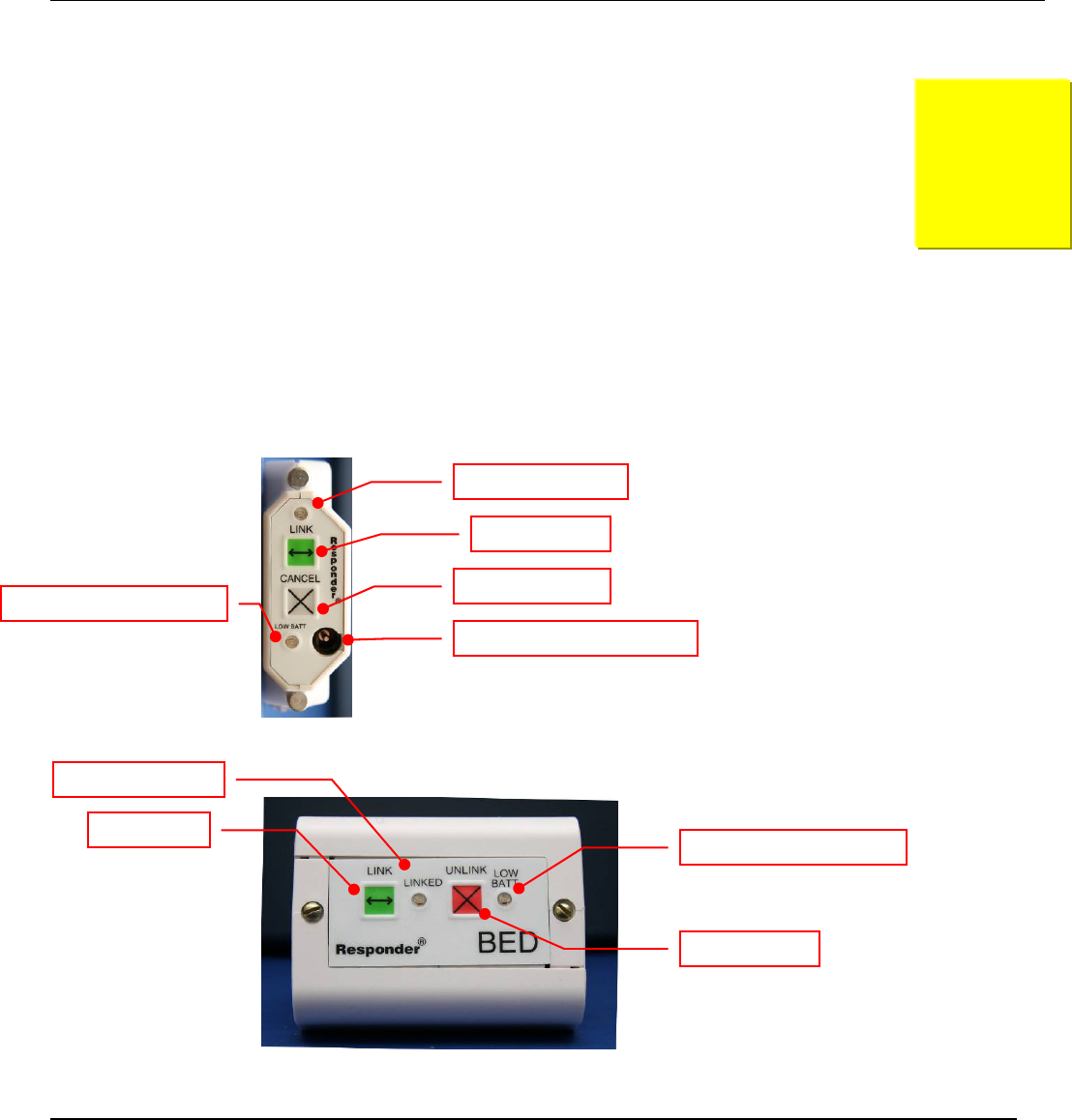
Figure 1: Generic Wall Unit
Figure 2: Bed Unit (represents both models)
Linking Bed and Wall Units
Here are some basic things to bear in mind:
9 A linked Bed Unit may not operate when positioned more than 35 feet (10 meters)
from its companion Wall Unit.
2
Link Indicator LED
Link Button
Cancel Button
External Power Port (unused)
Low Battery Indicator LED
Link Indicator LED
Unlink Button
Low Battery Indicator LED
Link Button
KI-2206 Responder® IV Wireless Bed Interface User’s Guide—Operation
Page 7 of 11 (11/28/06)
9 It does not matter which LINK button is pressed first to initiate the linking process.
You’ll then have five (5) seconds to press the LINK button on the companion unit once
you’ve initiated the linking process.
9 During the linking process, the green LINKED indicator on both units will flash.
9 The LINK indicator on the Wall Unit will light steadily if properly linked.
9 Test each link after it has been established.
9 In the unlikely event that linking does not occur after you engage in the following
steps, the Bed Unit and/or the Wall Unit will emit a continuous tone for about ten (10)
seconds.
To Link the Units:
1 Position the bed in a location near the Wall Unit, but where you can easily gain access
to both the Wall Unit and Bed Unit
¾ During the linkage process and thereafter, the Bed Unit must be no more than 35 feet
away from its companion Wall Unit.
2 Initiate the linking process by pressing the green LINK button on each Unit within five
(5) seconds of each other.
Figure 3: Green Link Button
¾ Each LINK button will emit a confirmation beep once pressed.
¾ The green LINK indicators on both Units will begin to flash.
¾ A double beep indicates a successful linkage.
¾ A successfully linked Bed Unit’s green LINKED indicator will flash for a few
seconds before turning off.
¾ A successfully linked Wall Unit’s green LINKED indicator will flash for a few
seconds, but then remain on.
¾ If the link attempt is unsuccessful for any reason, the Bed Unit and/or the Wall Unit
will sound a continuous tone for about ten (10) seconds. To immediately silence the
tone(s) manually, press the gray CANCEL button on the Wall Unit and the red
UNLINK button on the Bed Unit. As soon as the tones are canceled, you can repeat
step 2 (above) to attempt relinking.
or
Figure 4: Unlink/Cancel Buttons
Link Reminder Chirp
The Units are equipped with a Link Reminder feature. In the event that an unlinked Bed
Unit and an unlinked Wall Unit are within proximity of each other for about two (2)
minutes, a short chirp will sound at the unlinked Bed Unit. This chirp reminds staff that the
Bed Unit is not paired with a nearby unlinked Wall Unit(s); however, should you wish that
a Bed Unit not be linked, you’ll want to silence this reminder chirp. Do so by pressing the
red UNLINK button on the Bed Unit. The reminder chirps will return after an hour. If the
bed is moved, and is left in proximity of other unlinked Wall Units for a few minutes, the

KI-2206 Responder® IV Wireless Bed Interface User’s Guide—Operation
Page 8 of 11 (11/28/06)
chirp will return. Again, the Bed Unit should either be linked, or the UNLINK button
pushed to silence it.
Testing the Bed-to-Wall Link
Once the link has been established, you’ll want to test it by placing a Normal and Bed-Exit
call as follows.
To Test the Link:
1 Place a call from the Bedside Rails.
¾ The Call Assurance light on the associated Bed Station should light without delay.
¾ The Call Assurance light on the Bedside Rails should begin to flash briefly once
every two (2) seconds.
¾ A Normal (routine) call should appear at the Console.
2 Cancel the call at the Bed Station.
¾ All annunciations should cease.
3 Activate the bed’s Bed-Exit function.
¾ The Call Assurance light on the associated Bed Station should light.
¾ The Call Assurance light on the Bedside Rail should begin to flash once every two
(2) seconds.
¾ A Bed-Exit call should appear at the Console.
4 Cancel the Bed-Exit call at the Bed Station.
¾ All annunciations should cease.
Remedying Link Failures
Link failures may occur for a variety of reasons. Typically, failures occur because a bed is
moved beyond acceptable range (35 feet/10 meters).
When a link failure occurs:
¾ The Wall Unit will place a Bed-Out call.
¾ The Wall Unit’s green LINK indicator will fast flash continuously.
¾ To reestablish a link, cancel the Bed-Out call at the Bed Station and then repeat the
linking process above.
Should you not want the Units linked, you may press the CANCEL button on the Bed
Unit, and cancel the Bed-Out call at the Bed Station.
Terminating a Link
Should you ever wish to terminate a link between a Bed and Wall Unit, here’s how it’s
done.
To Terminate a Link:
1) Press the red UNLINK button on the Bed Unit.
KI-2206 Responder® IV Wireless Bed Interface User’s Guide—Operation
Page 9 of 11 (11/28/06)
Figure 5: Unlink Button
¾ The Unit will sound a single confirmation beep.
¾ The green LINK indicator will flash momentarily and then extinguish.
¾ A Bed-Out call will be placed by the associated Bed Station.
2 Cancel the Bed-Out call at the Bed Station.
Low Battery Alert
The Units are equipped with low battery indicators (LOW BATT). Low Batteries should
be replaced as soon as possible by trained personnel.
Here’s what else you need to know about low battery conditions:
9 In the event battery power is running low within the Bed Unit, the Bed Station will
place a Bed-Out call, and the Wall Unit will flash its red LOW BATT indicator
continuously.
9 Alert the staff responsible for replacing the batteries.
9 The batteries will last for about two weeks following the first low battery alert.
9 The Bed Unit will flash its red LOW BATT indicator only once per minute (to
conserve battery power).
9 The Bed-Out call will reoccur once every minute until the Wall Unit’s gray CANCEL
button is pressed.
Figure 6: Cancel Button
9 Pressing the CANCEL button will silence the alert for four (4) hours. If the condition
is not corrected within that time, the alert process will begin again.
9 After the batteries have been replaced and the Bed Unit returned to service, the Units
must be relinked.

KI-2206 Responder® IV Wireless Bed Interface User’s Guide—Operation
Page 10 of 11 (11/28/06)
Appendix A: FCC and IC
Compliance
Compliance Statement (Part 15.19)
This device complies with Part 15 of the FCC Rules.
Operation is subject to the following two conditions:
1) This device may not cause harmful interference, and
2) This device must accept any interference received, including interference that may cause
undesired operation.
Warning (Part 15.21)
Changes or modifications not expressly approved by the party responsible for compliance
could void the user’s authority to operate the equipment.
Warning
These devices (WBU and WWU) must not be collocated or operating in conjunction with
any other antenna or transmitter.
FCC Interference Statement
This equipment has been tested and found to comply with the limits for a Class B digital
device, pursuant to Part 15 of the FCC Rules. These limits are designed to provide
reasonable protection against harmful interference in a residential installation. This
equipment generates uses and can radiate radio frequency energy and, if not installed and
used in accordance with the instructions, may cause harmful interference to radio
communications. However, there is no guarantee that interference will not occur in a
particular installation. If this equipment does cause harmful interference to radio or
television reception, which can be determined by turning the equipment off and on, the user
is encouraged to try to correct the interference by one of the following measures:
Reorient or relocate the receiving antenna.
1) Increase the separation between the equipment and receiver.
2) Connect the equipment into an outlet on a circuit different from that to which the
receiver is connected.
3) Consult the dealer or an experienced radio/TV technician for help.
This portable transmitter with its antenna complies with FCC’s RF exposure limits for
general population / uncontrolled exposure.
A

KI-2206 Responder® IV Wireless Bed Interface User’s Guide—Operation
Page 11 of 11 (11/28/06)
Industry Canada Statement per Section 4.0 of RSP-100
The term "IC:" before the certification / registration number only signifies that the Industry
Canada technical specifications were met.
Section 7.1.5 of RSS-GEN
Operation is subject to the following two conditions:
1) this device may not cause harmful interference, and
2) this device must accept any interference received, including interference that may cause
undesired operation.