Raven 0630172368 RGL 600 Smartbar Transmitter User Manual 936a 1 pmd
Raven Industries RGL 600 Smartbar Transmitter 936a 1 pmd
UserManual.wiki
>
Raven
>
0630172368 User Manual
Users Manual
Navigation menu
Upload a User Manual
Namespaces
Wiki Guide
HTML
PDF
Info
Views
User Manual
Discussion / Help
Navigation

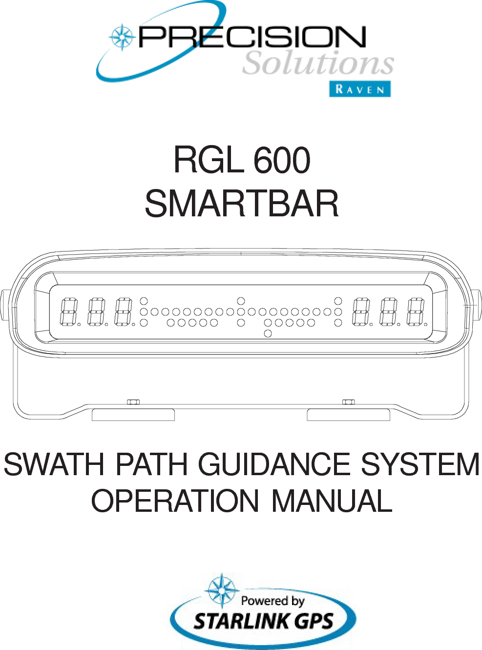

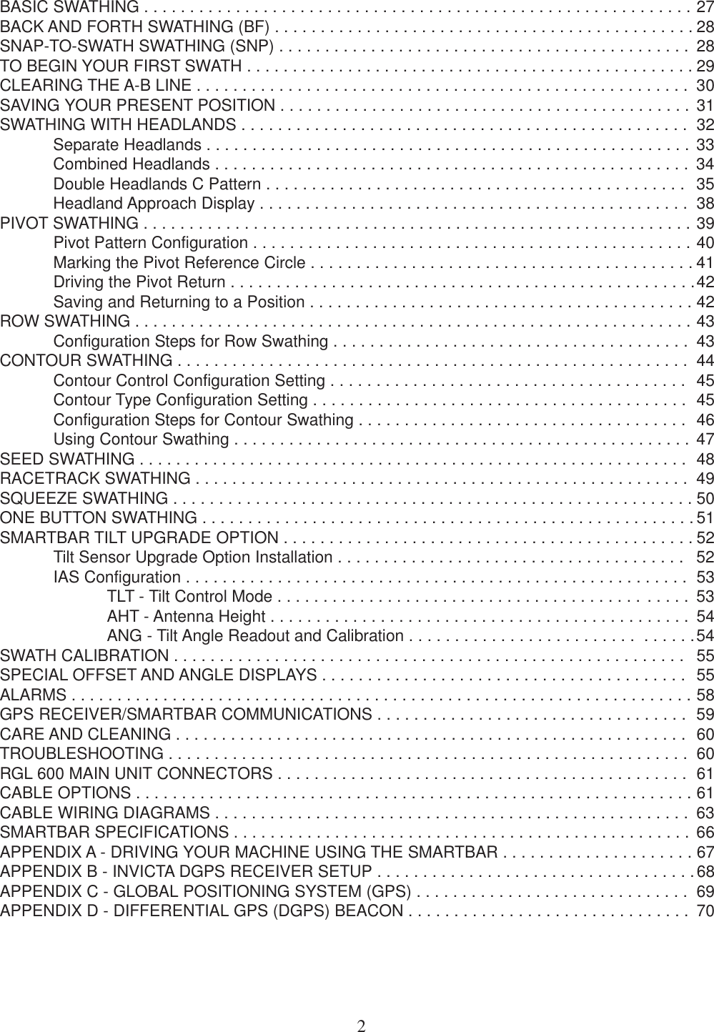
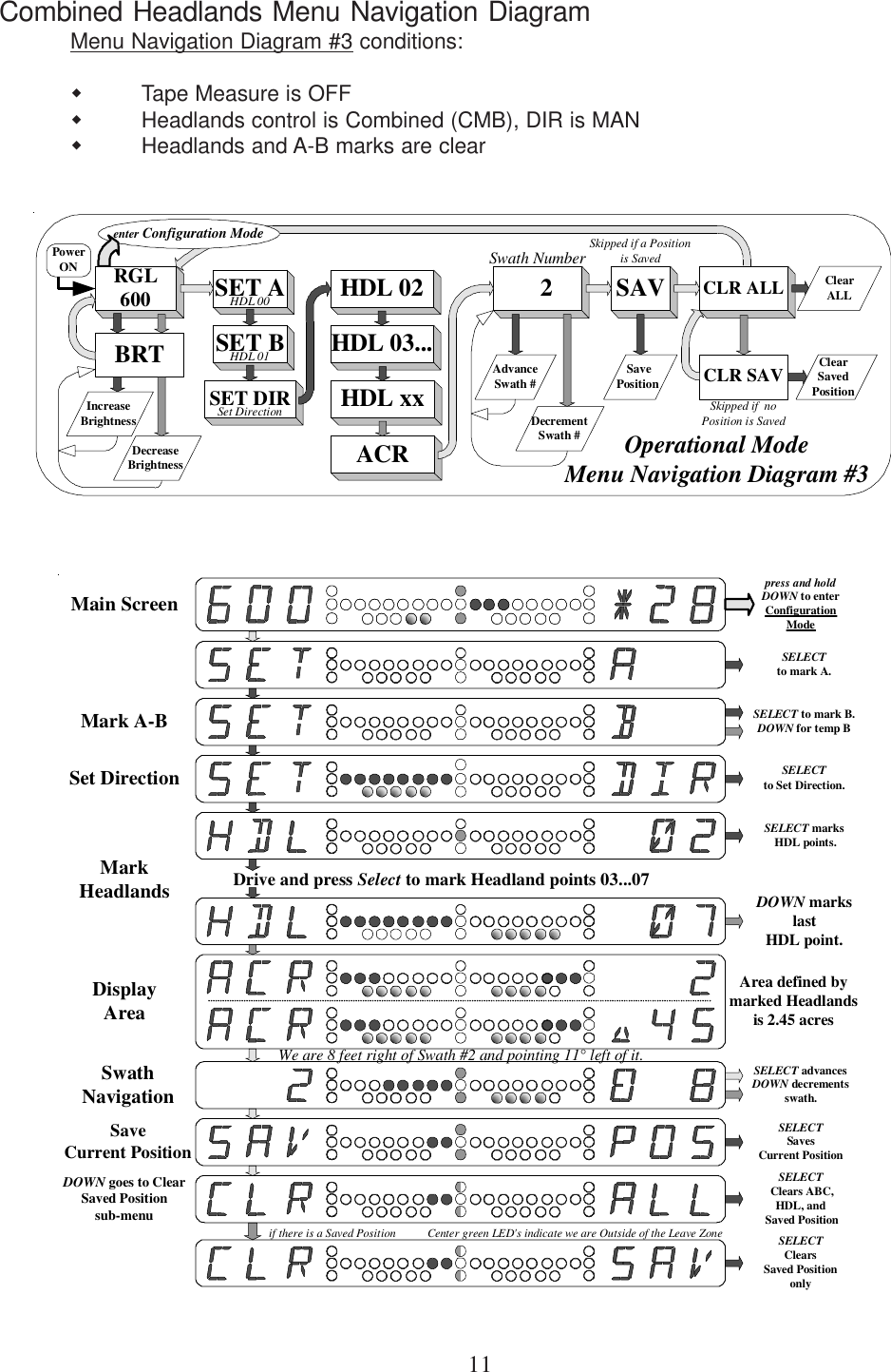
![7Notations used for display figures and menu navigation diagramsThe following notations are used to describe the Smartbar LED indicators and alphanumericdisplays:This example shows a multiple sequence alphanumeric display. In this example, 1.55 acresis displayed by alternating the right alphanumeric display between ‘ 1’ and ‘.55’. The Smart-bar display alternates between [a] and [b]. In some Configuration Mode displays, up to 5sequences are used to display large numeric values.The following notations are used for menu navigation diagrams:SWASWTSWASWTmain-menu item (Left alphanumeric display shows SWA)sub-menu item (Left alphanumeric display shows SWT)At the Swath (SWA) main-menu,press the DOWN button to move tothe Swath Type (SWT) sub-menu.Execute an action.For this example, Set the Tape Reference Point.Set TapeRefernce pointMENU Button pressed and releasedDOWN Button pressedSELECT Button pressedpress and hold the MENU Button for 3 secondsAutomatic (no button press)[a][b]- LED is OFF- LED is ON- LED is flashing ON/OFF- LED is flashing OFF/ON (used to denotate alternating flash when shown with )](https://usermanual.wiki/Raven/0630172368/User-Guide-371768-Page-12.png)
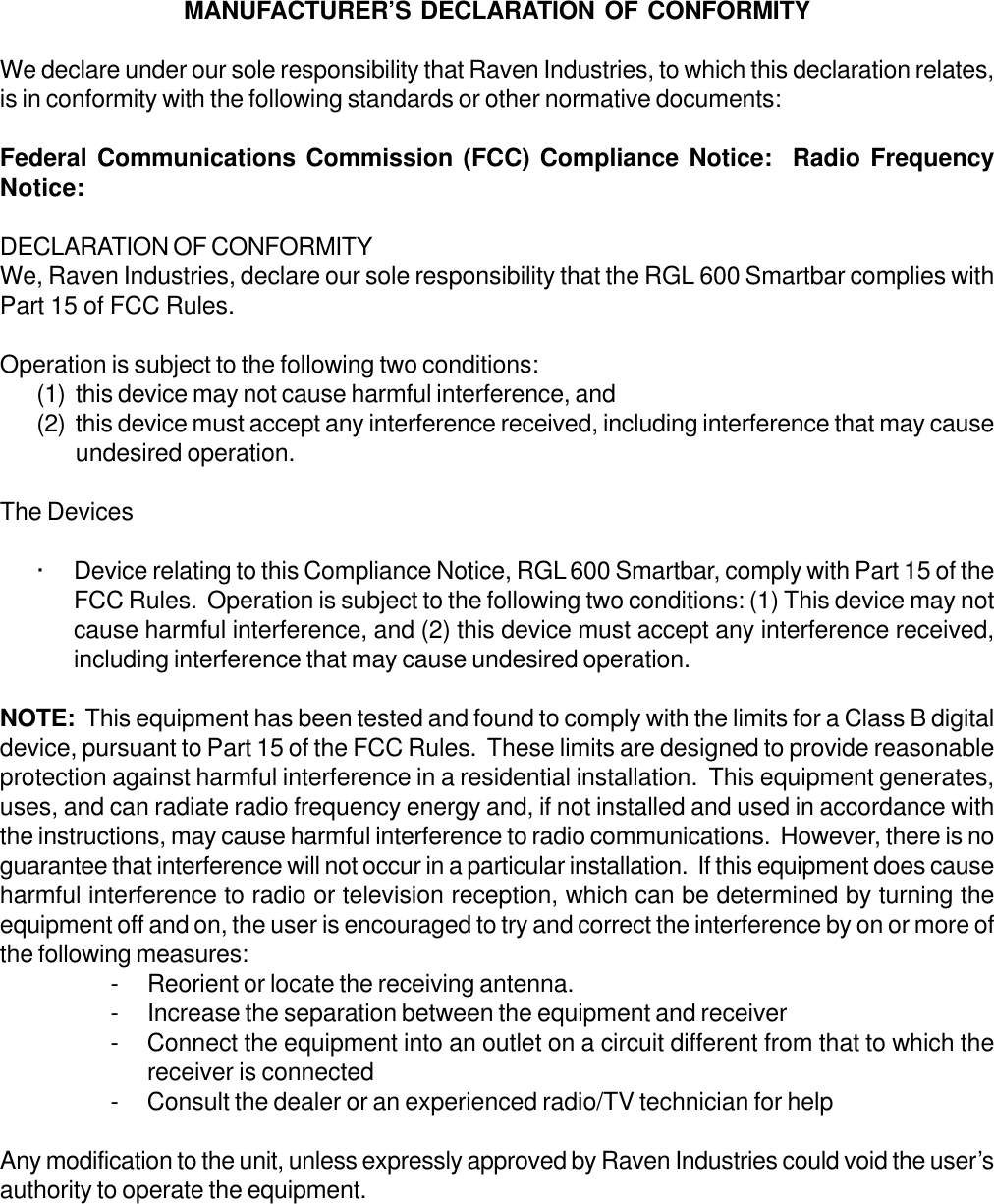
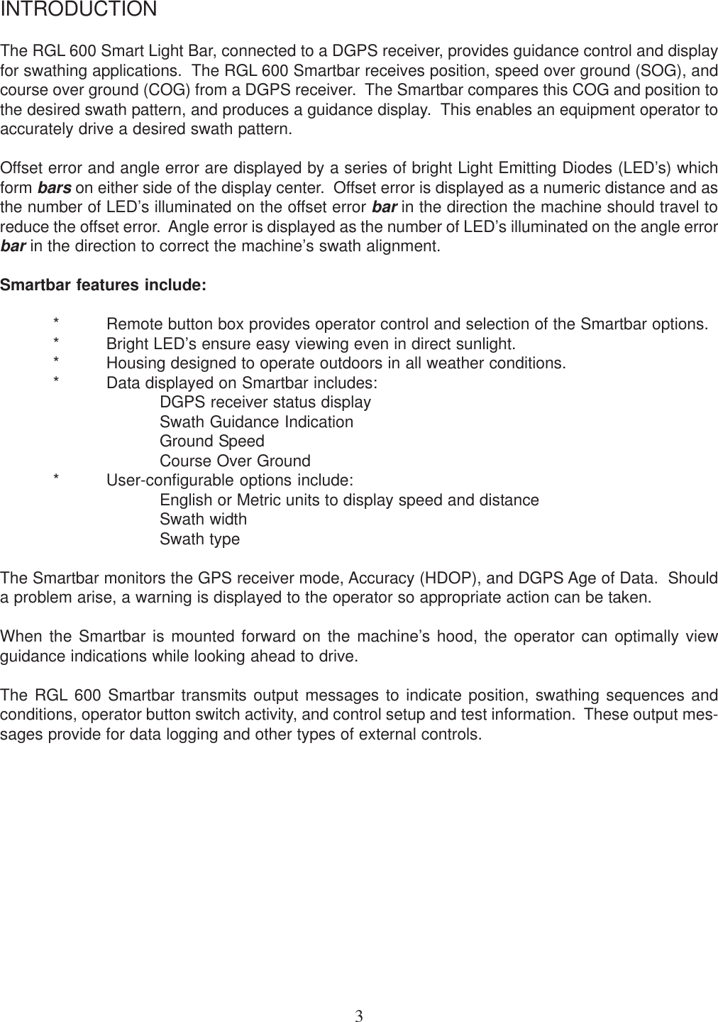
![13Entering and Leaving the Configuration ModeControlled access to the Configuration Mode prevents inadvertent entrance during normalOperational Mode activity. Once the Configuration Mode is entered, there are several mainmenus that are displayed sequentially by pressing the MENU button. Configuration Modemain menus are identified by the word “CON...FIG...URE...” displayed sequentially in the rightalphanumeric display (see the [GPS] main menu example below). The Configuration Modecan only be entered from the Operational Mode main screen [RGL 600]. To enter the Configu-ration Mode, press and hold the MENU button for approximately 3 seconds. When the[TO...CFG] screen shows (see below), the MENU button may be released. Press theSELECT button to enter the Configuration Mode or press the MENU button to return to the[RGL 600] main screen.The Configuration Mode GPS main menu is displayed first as shown here.Return to the Operational Mode from any Configuration Mode menu by pressing and holdingthe MENU button for approximately 3 seconds. When the [TO...OPR] screen shows (seebelow), the MENU button may be released. Press the SELECT button to return to theOperational Mode or press the MENU button to stay in the Configuration Mode.Press and holdMENU to enterConfigurationModeSELECTentersConfiguration ModePress MENU to cancelConfiguration Mode[c][d][a][b]Displaysequencesbetween[a], [b], [c], and[d]Typical of allConfiguration ModeMain MenusPress and holdMENU to return toOperational ModeSELECTreturns toOperational ModePress MENU to cancelOperational Mode](https://usermanual.wiki/Raven/0630172368/User-Guide-371768-Page-18.png)
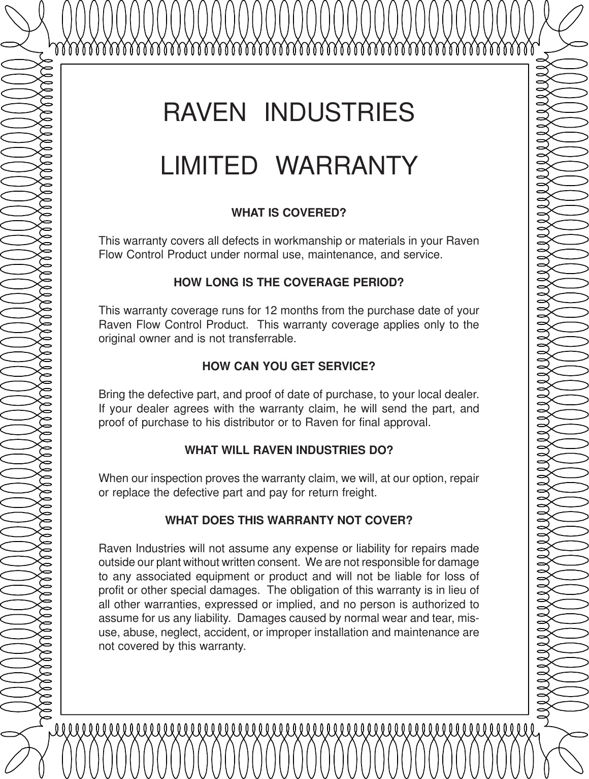
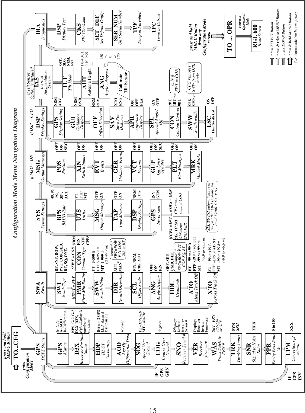
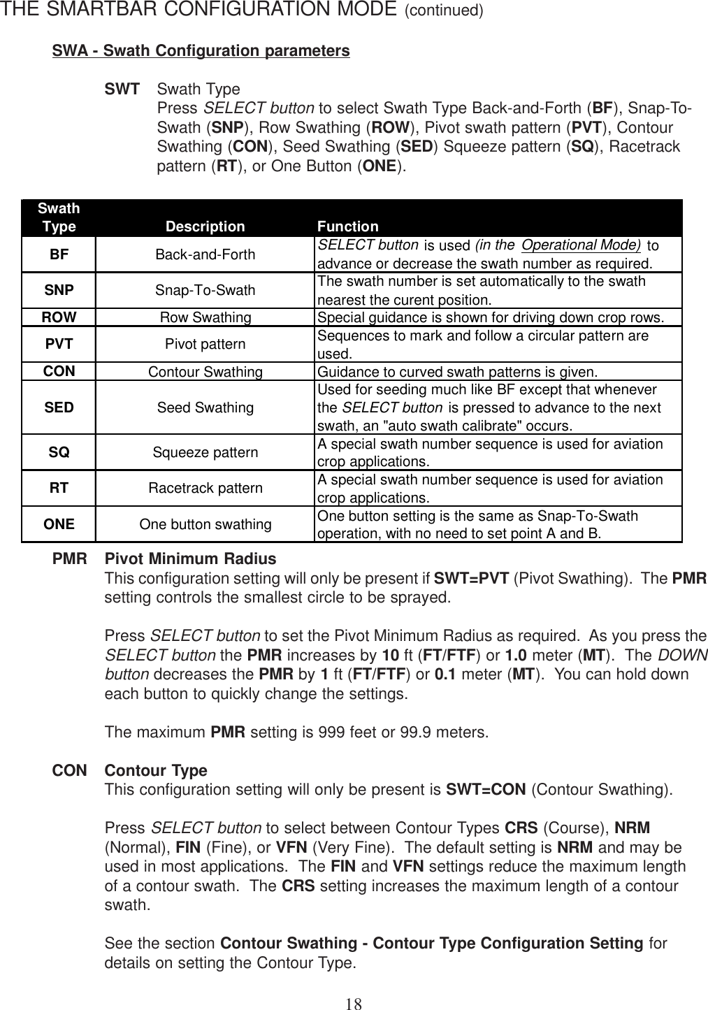
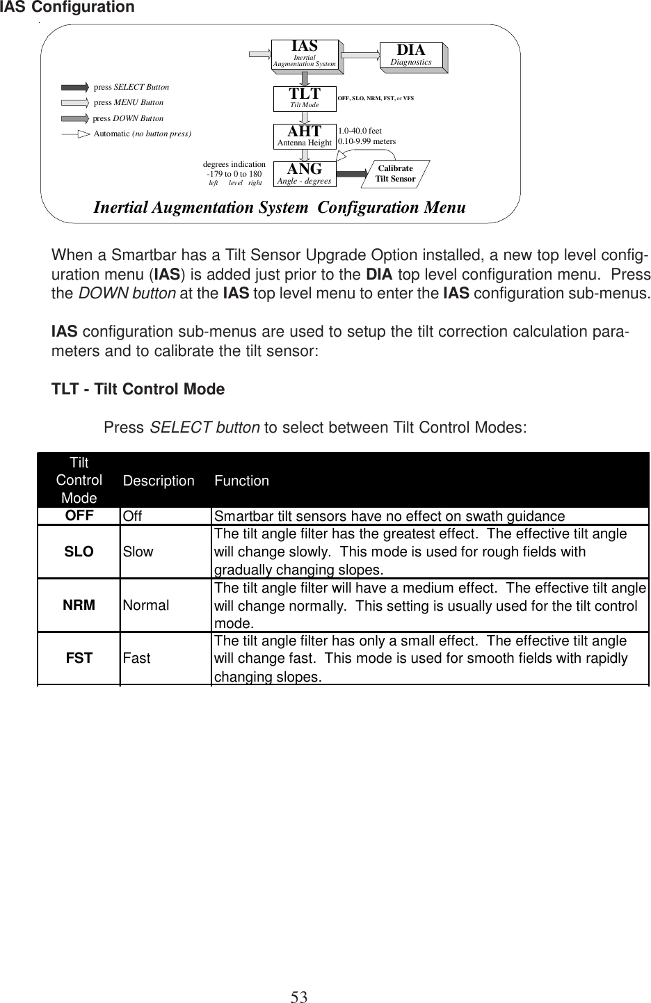
![14The Smartbar Configuration ModeThere are normally 7 main menus in the Configuration Mode as listed here:GPS GPS Receiver Status monitoringSWA Swath Configuration parametersSYS System Configuration (includes BAUD rate)MSG Output Messages control (present only if SYS-MSG=ON)DSP Display Settings (present only if SYS-DSP=CFG)IAS Inertial Augmentation System (configuration for optional tilt compensation)DIA Diagnostic Built-In TestingPressing the MENU button at a Configuration Mode main menu will view the next Configura-tion Mode main menu. Pressing the MENU button at last main menu will view the first mainmenu [GPS]. The SELECT button is not funtional for Configuration Mode main menus. Pressthe DOWN button to go down from a main menu, into its sub-menus. Then press the MENUbutton to go through the sub-menus. After the MENU button has been pressed for all of thesub-menus, the same main menu is displayed again. This provides a quick return to a sub-menu that may have been passed unintentionally. The DOWN button will reenter the samemain menu’s sub-menus, or the MENU button will proceed to the next main menu.The Output Messages control (MSG) main menu is present only if SYS-MSG is set on ON.The Display Settings (DSP) main menu is present only if SYS-DSP is set to configure (CFG).The Inertial Augmentation System (IAS) main menu is present only if optional tilt compensa-tion is installed.](https://usermanual.wiki/Raven/0630172368/User-Guide-371768-Page-19.png)
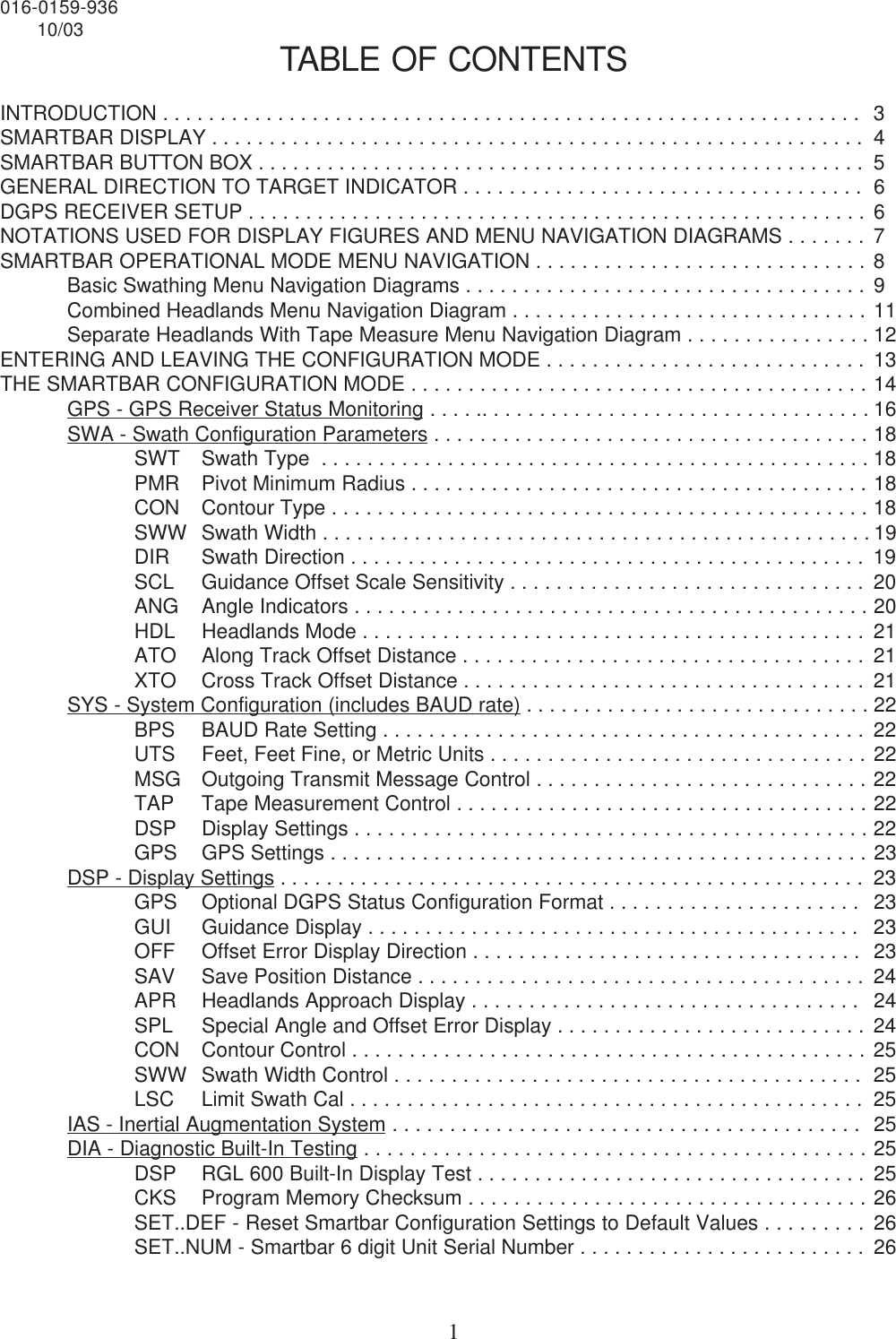
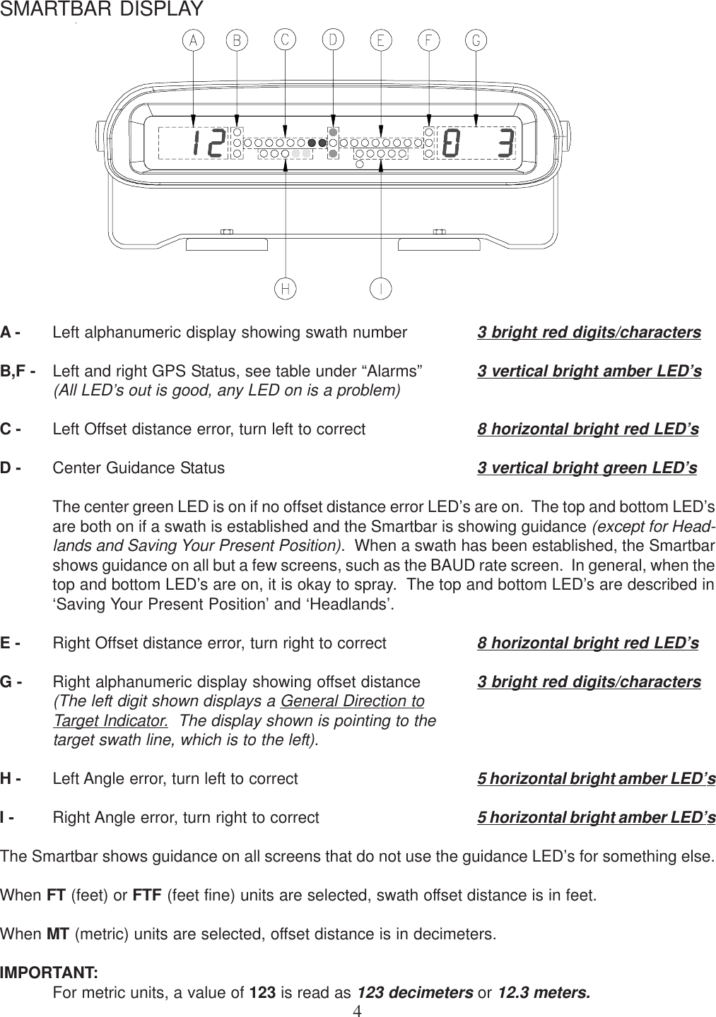
![26THE SMARTBAR CONFIGURATION MODE (continued)DSP - Diagnostic Built-In Testing (continued)CKS Program Memory ChecksumPress the SELECT button to execute a program memory checksum calculation. Thecalculated 8 Hexadecimal digit checksum is displayed in 4 display cycles. (see below)Firmware program integrity is validated if the indicated checksum matches a known orpublished checksum for the current version.SET..DEF - Reset Smartbar configuration settings to default valuesWARNING: All existing Smartbar configuration settings will be erased.Press the SELECT button to reset all Smartbar configuration settings to default values.When the SELECT button is pressed, the Smartbar will restart to the home screen withdefault values for all configuration settings.SER..NUM - Smartbar 6 digit Unit Serial NumberThis Serial Number matches the Model/Serial Number tag on the back of your Smartbar.It is important to supply this Serial Number when requesting product or technicalsupport.TPF Internal Board Temperature in Fo (Farenheit).TPC Internal Board Temperature in Co (Celsius).Temperature display menu only available in RGL600 with Tilt option installed.Display sequencesbetween[a], [b], [c], [d], [e].showing theHexadecimal number'1234FE78'[a][b][c][d][e][a][b]Display sequencesbetween [a] and [b]showingSerial Number314159](https://usermanual.wiki/Raven/0630172368/User-Guide-371768-Page-31.png)

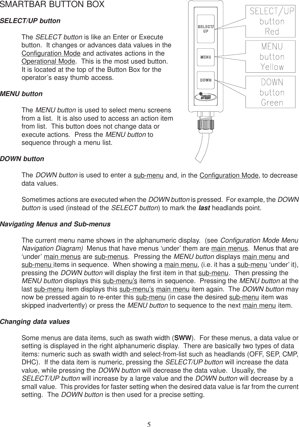
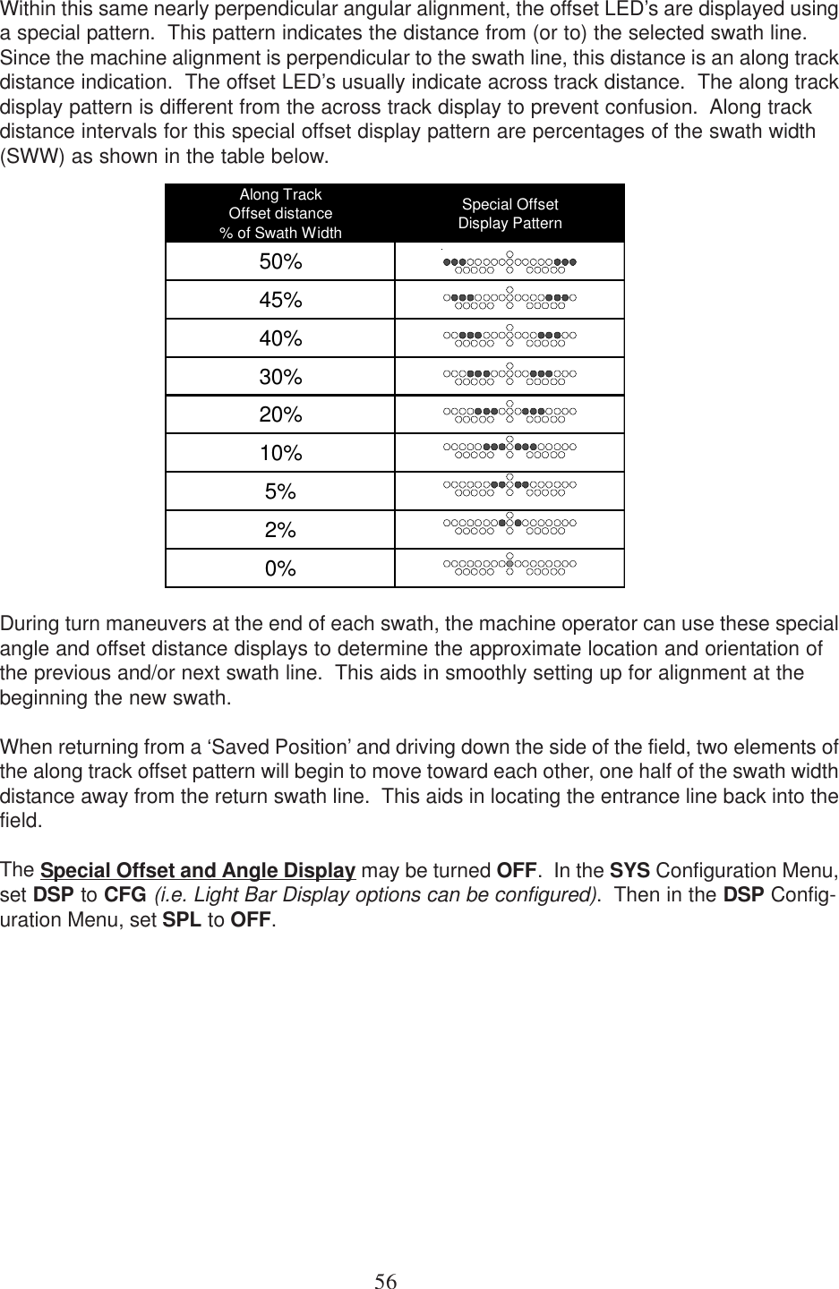
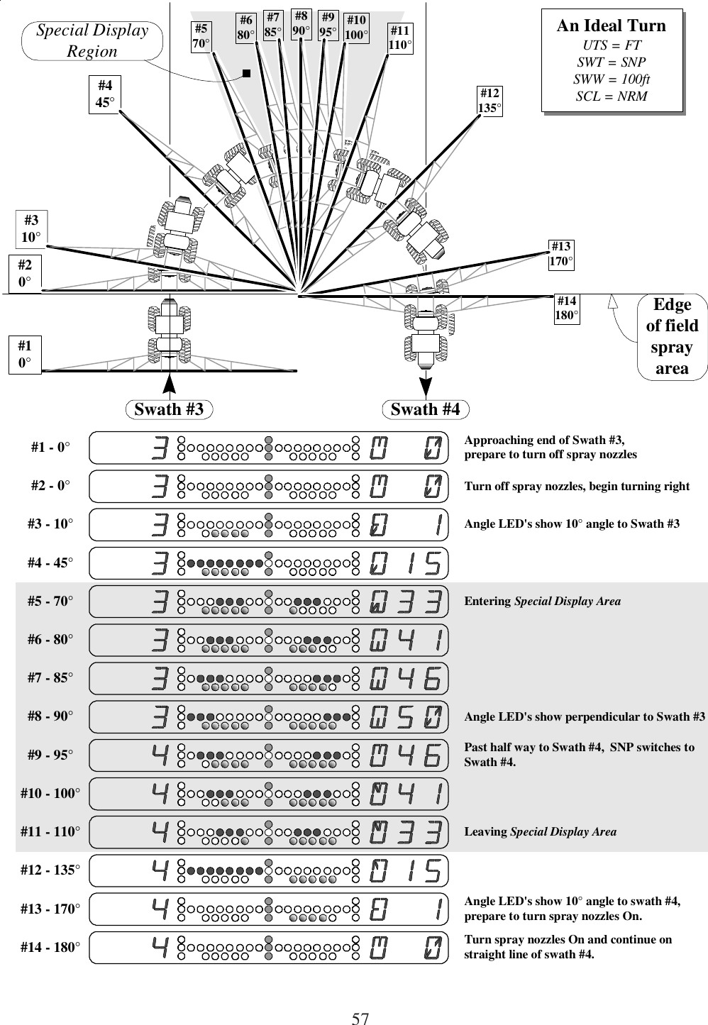
![55SWATH CALIBRATIONThe Swath Calibration feature is an aid for very accurate swathing requirements. The DGPSReceiver accuracy is high for short periods of time. When long time intervals occur duringswathing, small across track position drifts can be corrected using Swath Calibration. Themachine operator must be able to determine the precise corrected position of the currentswath line and position the machine to that point. Swath Calibration will adjust the AB linereference and all successive swaths to this adjusted point. Swath Calibration is limited to 1/4the current swath width setting. From the Swath Navigation screen, press and hold the MENUbutton for approximately 3 seconds. When the [CAL...SWA] screen shows, the MENU buttonmay be released. Press the SELECT button to calibrate the swath line to the current positionor press the MENU button to return to the Swath Navigation screen without changing theswath calibration.The swath calibration limit may be turned off. In the SYS configuration menu, set DSP to CFGthen in the DSP configuration menu, set DSP-LSC to OFF. When LSC-ON, the Swath Calibra-tion is limited to 1/4 of the current swath width setting. When LSC-Off, the Swath Calibrationlimit is bypassed.SPECIAL OFFSET AND ANGLE DISPLAYSSpecial offset and angle LED display patterns indicate that the Smartbar is nearly perpendicu-lar to swath line. This display pattern will usually be seen only when turning from one swath toanother or when leaving and returning from a ‘Saved Position’.See the diagram “An Ideal Turn” on page 57 for an illustration of how the angle LED’s indicateswath alignment between 70o and 110o (20o on either side of 90o, which is perpendicular).Notice the angle LED’s are all on (either left or right) from about 15o to about 70o. As theswath angle increases toward perpendicular, an additional angle LED will come for each 5ountil all angle LED’s are ON at 90o. As the swath angle continues to increase, beyond 90o,an angle LED will go off for each 5o until all angle LED’s on the original side are off. As theangle changes toward swath alignment, LED’s will begin to go off at about 15o (referenced tothe next swath line) and will all be off when alignment to the next swath is reached.Angle LED display patterns between 70o and 110o are shown in the following table.Machine Alignment with Swath Line Special Angle LED Display Pattern65707580859095100105110115](https://usermanual.wiki/Raven/0630172368/User-Guide-371768-Page-60.png)
![58ALARMSSystem performance can be adversely affected under certain operating conditions. Loss ofdifferential signal and/or poor satellite geometry can cause the accuracy of the system to fallbelow that required for precision guidance. Should conditions exist which cause the accuracyto lessen, the user is notified with one of three possible alarm conditions; GPS, Accuracy, orDifferential GPS. These alarms; G, A, D, are displayed on the far right side of the DGPSStatus Display Screen (Configuration Mode - GPS). All other screens display these alarmconditions as yellow LED’s along the far end of both sides of the Smartbar (refer to diagramitems B and F on page 4). Alarms are represented as follows:Alarm Description[G] GPS Alarm All 3 LED's on each side. Less than 4 satellites or receiver mode less than D3X.[A] Accuracy Alarm Bottom 2 LED's on each side. HDOP greater than 2.0.[D] Differential Alarm Bottom LED on each side. Age of Data greater than 120.No Alarms No LED's on each side[GPS] The system is not operating in three-dimensional Differential GPS mode. Atleast four (4) usable satellites, five (5) or more is preferable, must be commun-icating with the receiver along with a valid correction signal in order to operatein 3-dimensional DGPS mode.[Accuracy] The Horizontal Dilution of Precision (HDOP) is greater than two (2.0). HDOP isa fancy term for approximating the error in your position solution caused bypoor satellite geometry. Simply stated, it usually means that you do not haveenough satellites in view (should have a minimum of 5) or the antenna’s view ofthe sky is partially blocked. You can see the number of staellites being used bygoing to the DGPS status screen (Configuration Mode) and pressing the DOWNbutton.[Differential] The age of satellite differential correction data has exceeded 120 seconds.Your GPS receiver is not receiving the correction signal. It may be tuned to thewrong frequency, the service provider may be out of range or unavailable orthere may be some electrical noise interfering with the signal.The system should not be used when alarms are present. Many times the alarm conditionsare only temporary and will clear up by themselves. Should alarm conditions remain, refer tothe Troubleshooting section in this manual and the User’s Manual supplied with your GPSreceiver.](https://usermanual.wiki/Raven/0630172368/User-Guide-371768-Page-63.png)