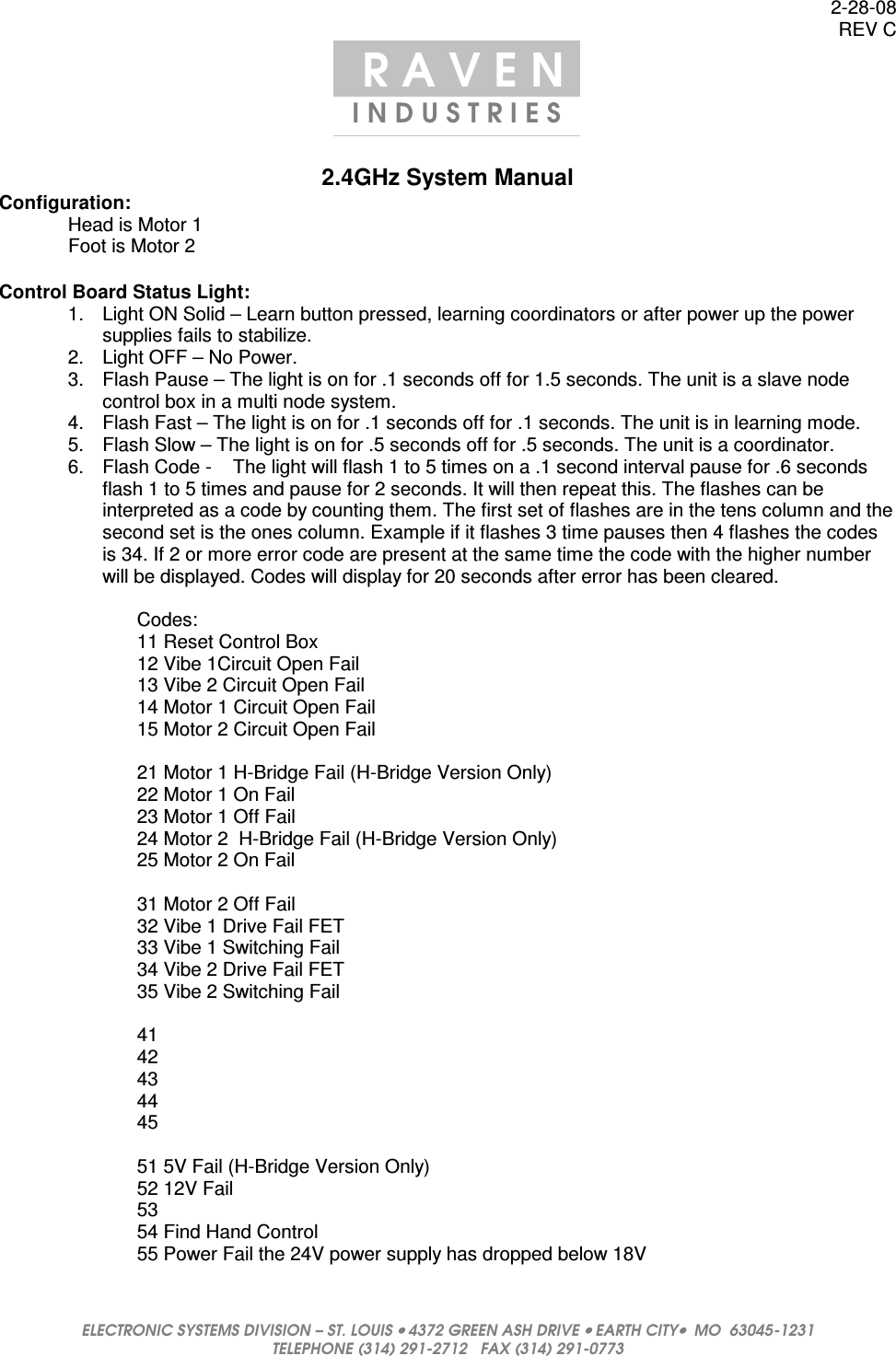
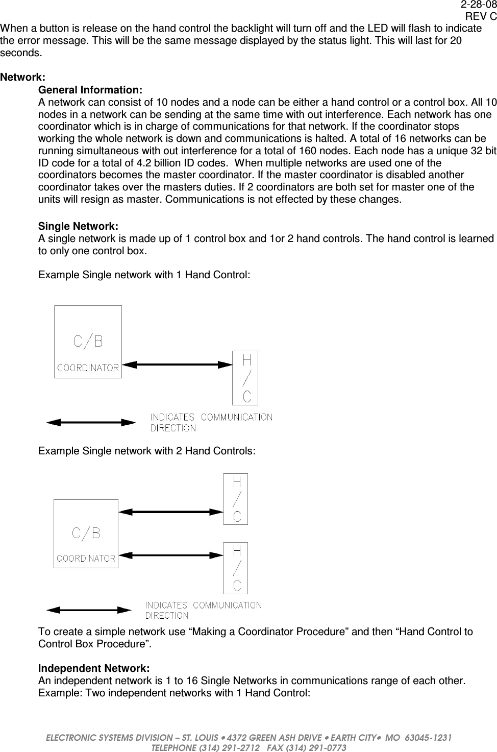
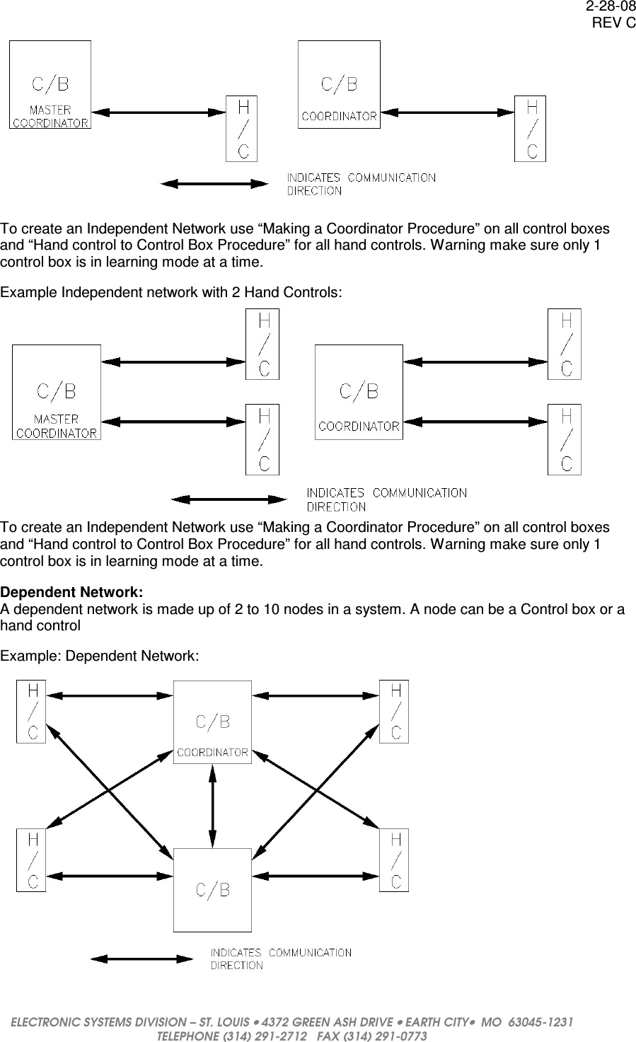
Raven E1005300 Hand Controller User Manual System Manul

Raven Industries Hand Controller System Manul

Users Manual Rev

2-28-08 REV C  ELECTRONIC SYSTEMS DIVISION – ST. LOUIS •••• 4372 GREEN ASH DRIVE •••• EARTH CITY••••  MO  63045-1231 TELEPHONE (314) 291-2712   FAX (314) 291-0773   R A V E N  I N D U S T R I E S   2.4GHz System Manual Configuration:   Head is Motor 1    Foot is Motor 2  Control Board Status Light: 1.  Light ON Solid – Learn button pressed, learning coordinators or after power up the power supplies fails to stabilize. 2.  Light OFF – No Power. 3.  Flash Pause – The light is on for .1 seconds off for 1.5 seconds. The unit is a slave node control box in a multi node system. 4.  Flash Fast – The light is on for .1 seconds off for .1 seconds. The unit is in learning mode. 5.  Flash Slow – The light is on for .5 seconds off for .5 seconds. The unit is a coordinator. 6.  Flash Code -    The light will flash 1 to 5 times on a .1 second interval pause for .6 seconds flash 1 to 5 times and pause for 2 seconds. It will then repeat this. The flashes can be interpreted as a code by counting them. The first set of flashes are in the tens column and the second set is the ones column. Example if it flashes 3 time pauses then 4 flashes the codes is 34. If 2 or more error code are present at the same time the code with the higher number will be displayed. Codes will display for 20 seconds after error has been cleared.  Codes: 11 Reset Control Box 12 Vibe 1Circuit Open Fail  13 Vibe 2 Circuit Open Fail  14 Motor 1 Circuit Open Fail 15 Motor 2 Circuit Open Fail  21 Motor 1 H-Bridge Fail (H-Bridge Version Only) 22 Motor 1 On Fail 23 Motor 1 Off Fail 24 Motor 2  H-Bridge Fail (H-Bridge Version Only) 25 Motor 2 On Fail  31 Motor 2 Off Fail 32 Vibe 1 Drive Fail FET 33 Vibe 1 Switching Fail  34 Vibe 2 Drive Fail FET  35 Vibe 2 Switching Fail   41 42 43 44 45  51 5V Fail (H-Bridge Version Only) 52 12V Fail 53  54 Find Hand Control 55 Power Fail the 24V power supply has dropped below 18V
2-28-08 REV C  ELECTRONIC SYSTEMS DIVISION – ST. LOUIS •••• 4372 GREEN ASH DRIVE •••• EARTH CITY••••  MO  63045-1231 TELEPHONE (314) 291-2712   FAX (314) 291-0773  When a button is release on the hand control the backlight will turn off and the LED will flash to indicate the error message. This will be the same message displayed by the status light. This will last for 20 seconds.  Network:   General Information: A network can consist of 10 nodes and a node can be either a hand control or a control box. All 10 nodes in a network can be sending at the same time with out interference. Each network has one coordinator which is in charge of communications for that network. If the coordinator stops working the whole network is down and communications is halted. A total of 16 networks can be running simultaneous with out interference for a total of 160 nodes. Each node has a unique 32 bit ID code for a total of 4.2 billion ID codes.  When multiple networks are used one of the coordinators becomes the master coordinator. If the master coordinator is disabled another coordinator takes over the masters duties. If 2 coordinators are both set for master one of the units will resign as master. Communications is not effected by these changes.    Single Network: A single network is made up of 1 control box and 1or 2 hand controls. The hand control is learned to only one control box.  Example Single network with 1 Hand Control:      Example Single network with 2 Hand Controls:   To create a simple network use “Making a Coordinator Procedure” and then “Hand Control to Control Box Procedure”.  Independent Network: An independent network is 1 to 16 Single Networks in communications range of each other. Example: Two independent networks with 1 Hand Control:
2-28-08 REV C  ELECTRONIC SYSTEMS DIVISION – ST. LOUIS •••• 4372 GREEN ASH DRIVE •••• EARTH CITY••••  MO  63045-1231 TELEPHONE (314) 291-2712   FAX (314) 291-0773   To create an Independent Network use “Making a Coordinator Procedure” on all control boxes and “Hand control to Control Box Procedure” for all hand controls. Warning make sure only 1 control box is in learning mode at a time.  Example Independent network with 2 Hand Controls:  To create an Independent Network use “Making a Coordinator Procedure” on all control boxes and “Hand control to Control Box Procedure” for all hand controls. Warning make sure only 1 control box is in learning mode at a time.    Dependent Network: A dependent network is made up of 2 to 10 nodes in a system. A node can be a Control box or a hand control    Example: Dependent Network:
2-28-08 REV C  ELECTRONIC SYSTEMS DIVISION – ST. LOUIS •••• 4372 GREEN ASH DRIVE •••• EARTH CITY••••  MO  63045-1231 TELEPHONE (314) 291-2712   FAX (314) 291-0773  To create a Dependent Network use “Making a Coordinator Procedure” then “Control Box to Coordinator Control Box Procedure” and then use “Hand control to Control Box Procedure” for all hand controls.  Note all salve node control boxes must be reset before the unit can be learned.  Learning:     Control Box Learn Modes: 1.)  A control box can be put into learn mode by pressing its learn button and then releasing after the status light turns on. When released the status light will flash fast to indicate the unit is in learn mode. 2.)  After powering up a control box the unit can be put into learn mode by pressing and holding the control box learn buttons on the hand control for 10 seconds. The hand control will do a slow yellow flash of the LED while the buttons are pressed. The control box can only go into this mode for 60 seconds after power. Control box status light will flash fast to indicate the unit is in learn mode. 3.)  A control box can be put into learn mode by pressing the button on the power down box for less than 2 seconds and then releasing. The light on the power down box will turn yellow and then start flashing.  Making a Coordinator Procedure If a control boxes is displaying a code of 11 the control box has been reset and must be initialized. Place the control box in learn mode buy using on the three methods described in “Control Box Learn Modes”  the status light will  stay on solid until if finds all the coordinators about 5 seconds then start flashing fast this will last for 20 seconds. When this is done the status light will start flashing slow to indicate that it has become a coordinator to save time in learning a hand control can be learned to the coordinator when the status light is flashing fast see “Hand Control to Control Box Procedure”.    Hand Control to Control Box Procedure Place the control box in learn mode see “Control Box Learn Modes” wait for the light to start flashing fast. Press and hold  the learn buttons on the hand control the light will start out red  then switch to flashing yellow 2 short pulse then turn on solid.  When the light on the hand control turns green the hand control has been learned.  If no control box is in learn mode the light will timeout after 15 seconds no learn will taken place.  Control Box to Coordinator Control Box Procedure Place the coordinator control box in learn mode this is control box with the status light flashing slow see “Control Box Learn Modes”. When the light starts flashing fast place the non coordinator control box in learn mode see “Control Box Learn Modes”. The status light on the non coordinator control box will start flashing fast and then stop when the unit has learned.  The status light will then start the flash pause sequence. The coordinator control box will switch to a slow flash after it acknowledges the control box has been learned. If the status light does not switch to a slow flash the learn button can be pressed to clear learn mode.   Note a control box can only be added to a network if its communications has been reset.    Hand Control to Slave Control Box Procedure Place the control box in learn mode see “Control Box Learn Modes” and wait for the status light to start flashing fast. Press and hold  the learn buttons on the hand control the light will start out red  then switch to flashing yellow 2 short pulse and then turn on solid.  When the light on the hand control turns green the hand control has been learned release the buttons.  The status light on the control box will stop flashing fast when it acknowledges the hand control has been learned.  Reset Communications: Communications can be reset by holding down the learn button and powering up the unit. A reset control box will flash a status code of 11.  Hand Control Button Timeout:
2-28-08 REV C  ELECTRONIC SYSTEMS DIVISION – ST. LOUIS •••• 4372 GREEN ASH DRIVE •••• EARTH CITY••••  MO  63045-1231 TELEPHONE (314) 291-2712   FAX (314) 291-0773  If a button on the hand control is pressed for longer than 50 seconds the hand control will go to sleep. To recover from this sleep all hand control buttons must be released for a 1 seconds before the unit will respond to a button command.   Hand Control FCC Testing:  If the Hand Control has the FCC bit set in the config byte FCC mode is enabled. Using a hand control with all 8 top buttons like an Scape 2 is required for all the FCC functions.   Functions: Constant Carrier:     Foot up and Down pressed at the same time and Enables FCC mode Constant Modulation:  Head Up and Down pressed at the same time and Enables FCC mode Set Channel Hopping:   POS1 and POS2 pressed at the same time. Clear Channel Hopping:   POS2 and POS3 pressed at the same time. FCC OFF:     POS1 and POS3 pressed at the same time. Inc Channel:                       POS2 and Set pressed at the same time.  The backlight turns off when in FCC testing Mode. When in Constant Carrier the light is yellow and green when in Constant Modulation. The light will flash when channel hopping is enabled and will be on solid when disabled. Channel hopping will cycle thru all 16 channels. Inc Channel will increment the channel.  Hand Control Status Light: When the status light is on solid red the hand control is waiting for a sync signal from the control box or the hand control has not been learned to any network.  When the status light is flashing green the hand control is sending data.    A yellow flashing status light indicates that the unit is in one of the 2 learn modes.   Error Codes – After a command button is released the hand control will flash red any error code from the control box for 20 seconds. See flash Code in Control Board Status Light for flash information.  Control Box Diagnostics: The control box will flash the status light when diagnostics has identified a fault condition. The status light will flash the code for 20 seconds after the code has been cleared.  Vib Motor Faults:  Drive fail – this error is caused when the motor drive circuit fails to turn on. The fault code will be displayed on the status light.  Circuit Open Fail – this is caused when the motor is off and the ATD has less than 1 volt. The fault code will be displayed on the status light.  Switching Fail – this error is caused when the motor is running and the ATD voltage is not above 2 Volts.  Lift Motor Faults:  H-bridge shut down – this error is caused when the H-bridge has detected a fault. The fault is sent to the micro and that motor is turned off. If a favorite position or preset position was activated it will be shut down. The fault code will be displayed on the status light.
2-28-08 REV C  ELECTRONIC SYSTEMS DIVISION – ST. LOUIS •••• 4372 GREEN ASH DRIVE •••• EARTH CITY••••  MO  63045-1231 TELEPHONE (314) 291-2712   FAX (314) 291-0773  Motor failed to turn on – this error is caused when the motor is running and the motor ATD input has fallen below 1 Volt. The motor is turned off and favorite position or preset position is canceled.  The fault code will be displayed on the status light as long as the motor button is being pressed.  Motor failed to turn off – this error is caused when the motor is off and the motor ATD input has fallen below 2 Volts.  The 24V to the motors is turned off.  The fault code will be displayed on the status light.  The power must be removed for this error to be cleared.  Circuit Open Fail – this error is caused when the motor limit switches can not be read. The fault code will be displayed on the status light.  System Faults:   Power fail – this error is caused when the ATD input for the 24 volts has fallen below 18 volts.  The 24V power relay is turned off so all voltage to the motors has been turned off.  The relay will stay off for 20 seconds after the voltage rises above 18 volts. The fault code will be displayed on the status light.  Power up fail – this error is caused when the unit is powering up the 24V is less than 22 volts or the 12V is below 11 volts.  The status light will stay on solid.  5V fail – this error is caused when the 5V power supply drops below 4 volts.  The fault code will be displayed on the status light.   12V fail – this error is caused when the 12V power supply drops below 11volts.  The fault code will be displayed on the status light.    Hand Control Find: The find function is activated by press the lean button on the control box for 4 seconds at which time the status light will start flashing code 54. The button can be released and the hand control will start sounding its beeper after it receives the find command. The hand controls wakes up every 30 seconds looking for a signal. The function can be canceled by pressing a button on the beeping hand control or by pressing the learn button. If no hand control is found the control box will clear the function after 120 seconds.  Power Down Box: Power Down with power applied: The power down box can be use for three different types of functions learn, find and flat. The length of time the button is pressed determines what function is active.  From .5 to 2 seconds the learn function will be activated. From 2 seconds to 5 seconds the find feather is active.  This can be seen in the power down light flashing a code of 54 with the yellow LED. If the time is held for over 5 seconds the flat feature will start running and the LED will stop flashing the find code. The time the button is held is determined by when the button is released. At that time the first 2 functions will start their execution. If a the find function or learn function is active it may be cleared by pressing the power down button  for .5 seconds to 2 seconds and releasing.   Power Down with power disconnected: Press and hold the flat button on the power down box the light turn on solid red. The head will start running down until the limit switch is hit. Then the foot will drive down until its limit switch is pressed.  Lift Motor Operation: When a lift motor is activated the vibe motors are turned off so all the power can be supplied to the life motor. When the lift motor stops running the vibe motor will be turned back on.  Flat:
2-28-08 REV C  ELECTRONIC SYSTEMS DIVISION – ST. LOUIS •••• 4372 GREEN ASH DRIVE •••• EARTH CITY••••  MO  63045-1231 TELEPHONE (314) 291-2712   FAX (314) 291-0773  When a flat function is being executed the motor 1 lift motor will turn on first and a few seconds later the motor 2 lift motor will turn on. This is done so the inrush current of the motor is not doubled when turning both motors on at the same time.  FCC: Changes or modifications not expressively approved by the party responsible for compliance could void the user's authority to operate the equipment.
2-28-08 REV C  ELECTRONIC SYSTEMS DIVISION – ST. LOUIS •••• 4372 GREEN ASH DRIVE •••• EARTH CITY••••  MO  63045-1231 TELEPHONE (314) 291-2712   FAX (314) 291-0773   Hand Controls Supported:
2-28-08 REV C  ELECTRONIC SYSTEMS DIVISION – ST. LOUIS •••• 4372 GREEN ASH DRIVE •••• EARTH CITY••••  MO  63045-1231 TELEPHONE (314) 291-2712   FAX (314) 291-0773  

Navigation menu