Users Manual

Rev. A Date 10/02
Smartlink ™
Anhydrous Ammonia Fluid
Monitoring System
Owner’s Guide
Page - 2 – Fluent Systems – SmartLink System
Table of Contents
Instruction to the User Page 2
Introduction Page 3
Features / System Components Page 4
Cab Unit Quick Reference Guide Page 8
Using the Smartlink (tm) System Page 9
Troubleshooting Page 14
Instruction to the User
This equipment has been tested and found to comply with the limits for a class B digital
device, pursuant to part 15 of the FCC rules. These limits are designed to provide
reasonable protection against harmful interference in a residential installation. This
equipment generates uses and can radiate radio frequency energy and if not installed and
used in accordance with the instructions, may cause harmful interference to radio
communications. However, there is not guarantee that interference will not occur in a
particular installation. If this equipment does cause harmful interference to radio or
television reception which can be determined b turning the equipment off and on, the user
is encouraged to try to correct the interference by one or more of the following measures:
Reorient or relocate the receiving antenna
Increase the separation between the equipment and the receiver.
Consult dealer or an experienced radio/TV technician for help.
This equipment has been certified to comply with the limits for a class B computing device,
pursuant to FCC rules. In order to maintain compliance with FCC regulations, shielded
cables must be used with the equipment. Operation with non-approved equipment or
unshielded cables is likely to result in interference with radio and TV reception. The user is
cautioned that changes and modifications made to the equipment without the approval of
the manufacturer could void the user’s authority to operate this equipment.
Page - 3 – Fluent Systems – SmartLink System
Introduction
Congratulations on your purchase of the Smartlink (tm) monitoring system from Fluent
Systems. Smartlink (tm) is an innovative electronic system that allows you to continuously
monitor the application of anhydrous ammonia fertilizer from within the tractor cab. This
patent-pending product utilizes modern RF and electromagnetic sensing technologies in a
novel and revolutionary way and dramatically improves the process by which anhydrous
ammonia is applied to your field.
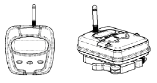
The Smartlink (tm) is a two-module system composed of a tank module that sits atop the
field tank and a cab module that is positioned within the tractor cab.
The tank module can be set directly on top of the existing fluid level gage with no
modifications required to the tank and no tools necessary.
The tank module continuously monitors the fluid level within the field tank and then sends
it in a wireless fashion to the display module mounted inside the tractor cab. The display
module receives the signal from the tank module, decodes the information and displays
fluid level to the user via a liquid crystal display.
The cab module allows the farmer to quickly input implement and tank size. This
information is processed along with groundspeed data from the tractor to output other
useful information to the farmer including application rate per acre, time remaining until
tank is empty and a "tank-empty" audible alert. The Smartlink (tm) is a capable
agricultural aid that provides convenience and added functionality not present today.
The Smartlink (tm) is a useful addition to the existing process of applying anhydrous
ammonia to farmland worldwide. It solves the difficult task of measuring fluid in a
hazardous environment while remaining completely safe to use. Information gathered by
the Smartlink (tm) can be used during application to increase operator efficiency and
decrease common problems associated with the current method. It also accurately reports
fertilizer application rate per acre, which adds greatly to the farmer's information.
The Smartlink (tm) is a system that includes one display module and one tank module,
along with necessary groundspeed interface, power cable and cab mounting hardware.
The product carries a one-year limited warranty.
Page - 4 – Fluent Systems – SmartLink System
Features and System Components
Your Smartlink (tm) System comes complete and ready to use with the following
components:
Cab Module Tank Module Windshield Adaptor
Ground Speed Adaptor 12 V Cigarette Lighter Adaptor Carrying Case

Page - 5 – Fluent Systems – SmartLink System
Operation:
General Operating Conditions:
Tank Unit Cab Unit
Maximum Temperature XX degrees F XX
Minimum Temperature XX degrees F XX
The Smartlink (tm) system has been designed for durable, robust operation and should
withstand years of use. The unit does contain precision electronic components and should
be treated carefully to ensure trouble free operation.
Do not expose the either Cab or Tank unit to excessive heat or cold.
The Tank unit has been designed to be water and dust resistant. Prolonged exposure to
driving rain, excessive sleet or snow should be avoided.
If the Tank unit will not be used for extended periods of time, the unit should be removed
from a tank and stored inside it’s protective case. The batteries should be removed to
prevent leakage.
Do not leave the Cab Unit in excessive heat or cold or direct sunlight for prolonged periods
of time. The user should be aware that extreme temperatures inside tractor cabs can
cause damage to the Cab Unit.
Avoid exposing the Cab Unit to extremely dusty conditions.
Avoid dropping either the Cab or Tank unit. While both units have been designed for shock
and vibration resistance, sensitive electronic components can be damaged due to excessive
shock or vibration.
Tank Unit Batteries
The Tank unit runs on three AA sized batteries. Do not mix old batteries with new
batteries. Do not use different types of batteries together. There is no need to turn the
tank unit on or off. Under normal use, the tank unit will run three months before needing
to change batteries. If the tank unit will be left unused for prolonged periods of time, the
batteries should be removed to prevent leakage and damage to the unit.
If battery leakage occurs, wipe off any deposits in the battery compartment and install new
batteries.
Page - 6 – Fluent Systems – SmartLink System
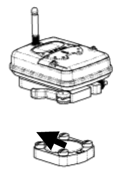
Installation of the Tank Unit
The Tank Unit has been designed with a “Quick Release
Clamp” intended to allow for easy installation to your
existing tank gage without modifications or tools.
The Tank Module has been optimized to specifically
work with Rochester brand gages. While the tank
module may operate acceptably with other type of
gages, the optimal operation cannot be assured. For
best results, ask your distributor to replace the fluid
gage with Rochester brand, model XXXX gages.
The Quick release clamp can be adjusted to
accommodate variations from clamp to clamp. Use a
tool to adjust the nut until the unit is securely fastened
to the gage with the clamp lever thrown closed.
!Important! For proper operation, the Tank Unit MUST be mounted on the gage with the
top of the unit facing the top of the gage. Failure to mount the Tank Unit in the correct
orientation will result in incorrect readings.
Tank Unit Operation
When the tank unit is placed on the gage it will momentarily flash a letter code indicating
that it has recognized the type of gage it is mounted on. This letter code can be used by
factory personnel in troubleshooting your unit should you experience any problems. Once
the tank unit is placed onto the tank it will immediately display the volume of fluid currently
in the tank, as reported by the existing gage. Before tightening down the gage you should
ensure that the reading on the LCD display of the tank module agrees with the reading on
the gage. If they do not agree, refer to the Troubleshooting section of this manual.
A blinking dot on the LCD display indicates every time the tank volume is sampled by the
tank unit. The tank unit will sample the tank volume approximately every second.
Approximately every ten seconds, the tank module will broadcast the average reading from
the tank to the cab unit. This averaging is one of the ways that the Smartlink (tm) system
compensates for the sloshing of the ammonia within the tank.
Cab Unit Power
The display unit will operate on either 3AA batteries or a 12Volt Power adaptor supplied
with the unit.
Use only the 12 Volt power adaptor supplied with the Smartlink (tm) system. Do not use
any other kind of adaptor or damage to the unit can occur.
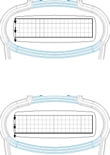
Top of Gage
Page - 7 – Fluent Systems – SmartLink System
Do not mix old batteries with new batteries. Do not use different types of batteries
together. Under normal use, the tank unit will run eight hours before needing to change
batteries. If the Cab unit will be left unused for prolonged periods of time, the batteries
should be removed to prevent leakage and damage to the unit.
If battery leakage occurs, wipe off any deposits in the battery compartment and install new
batteries.
For best operation, the Cab Unit should be connected using the 12 Volt Power Adaptor
provided with you system. The 12 volt Adaptor can be connected at any time, without
having to turn off your unit.
Installing the cab unit using the windshield adaptor
A windshield adaptor with convenient suction cup has been supplied with your Smartlink
(tm) system. For best results, carefully clean your windshield with the alcohol pad
provided before securing the suction cup.
Connecting the Ground Speed Adaptor Cable
In order to make full use of the reporting features of your Smartlink (tm) System you will
need to connect your tractor groundspeed radar to the back of the Cab Unit with the cable
provided. Connecting your Smartlink (tm) system to the groundspeed radar will allow
Smartlink (tm) to calculate useful information including your acres covered, tractor ground
speed and average application rate. Without tractor ground speed you will still have be
able to monitor the fluid level in your ammonia tank, but will not be able to see this other
information. This groundspeed adaptor cable plugs into the phone style jack in the back of
the Cab Unit and connects to the output from your existing groundspeed radar unit. If the
cable does not match the connector inside your Cab, see your distributor.
Calibrating your Groundspeed Radar
Before using your Smartlink (tm) System with your Groundspeed Radar Unit you must first
calibrate the Radar. This compensates for different types of radar and differences in the
way in which your radar is mounted on your tractor.
You MUST calibrate the groundspeed radar on YOUR tractor. This calibration must be
repeated any time you move the radar to a different tractor, even if they use the same
brand of radar. Once completed however, the calibration is stored in the Cab unit and
does not have to be repeated even if the unit is turned off or the batteries are removed.
To calibrate you groundspeed radar, access the SETUP GROUNDSPEED RADAR routine
through the SETUP menu on the Cab Unit.
Connect your cable
Mark off EXACTLY 200 feet on the ground.
Page - 8 – Fluent Systems – SmartLink System
Drive your tractor to the start of your 200 foot path and press START
Drive your tractor to the end of the 200 foot path and press Finish
Go to the TRACTOR GROUNDSPEED menu and make sure the unit is reading out correctly.
Cab Unit Quick Reference Guide
Page - 9 – Fluent Systems – SmartLink System
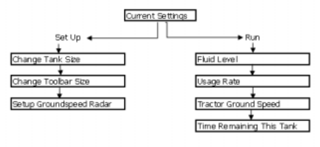
Using the Smartlink (tm) System
Current Settings Screen
This screen is the MAIN menu
for the Smartlink (tm) System
and displays the current settings
for the tanksize and toolbar size.
To ensure that the usage
calculations reported by
Smartlink (tm) are correct, you
should always check to make
sure these settings agree with
your field equipment.
The Setup Menus
The Smartlink (tm) System has three setup menus that are used to ensure that your unit
has the proper information about your particular field equipment
Change Tank Size
This menu is used to select the
proper tank that you are currently
using. The size of the tank is used
for application rate calculations.
Selecting YES at this menu allows
you to scroll between common
tank sizes. When you’ve selected
the correct size, press DONE to
confirm your setting. The tank size
is stored in the memory of your
Cab Unit and will remain the same
until you change it. It is,
therefore, not necessary to re-
enter the tank size unless you change to a different tank
CURRENT SETTI NGS
TANKSI ZE = 1850 GAL
T OOL BAR = 4 5 0 GAL
SETUP OFF RUN
CHANGE TANK SI ZE
1850 Gal l ons
YES NO
Page - 10 – Fluent Systems – SmartLink System
Change ToolBar Size
Selecting NO from the CHANGE
TANK SIZE screen access the
Change Toolbar Size Screen.
This menu is used to select the
proper tank that you are
currently using. The size of the
tank is used for application rate
calculations. Selecting YES at
this menu allows you to scroll
between common tank sizes.
When you’ve selected the
correct size, press DONE to
confirm your setting. The tank
size is stored in the memory of your Cab Unit and will remain the same until you change it.
It is, therefore, not necessary to re-enter the toolbar size unless you change to a field
implement
Setup Ground Speed Radar
Selecting NO from the CHANGE
TOOLBAR SIZE screen will
access the screens necessary to
setup the ground speed radar.
Before using your Smartlink (tm)
System with your Groundspeed
Radar Unit you must first
calibrate the Radar. This
compensates for different types
of radar and differences in the
way in which your radar is
mounted on your tractor.
You MUST calibrate the groundspeed radar on YOUR tractor. This calibration must be
repeated any time you move the radar to a different tractor, even if they use the same
brand of radar. Once completed however, the calibration is stored in the Cab unit and
does not have to be repeated even if the unit is turned off or the batteries are removed.
Monitoring Fluid Level with the Smartlink (tm) System
There are four monitoring screens available with the Smartlink (tm) System that are all
accessed through the RUN selection on the current settings screen.
CHANGE TOOL BAR SI ZE
450 Inches
YES NO
SETUP
GROUNDSPEED RADAR?
YES NO
Page - 11 – Fluent Systems – SmartLink System
Fluid Level Screen
The Fluid Level Screen acts
as a digital level gage,
showing the current level of
the ammonia in the tank as
both a percentage and a
graphic bar. The fluid level
will be displayed any time
the Cab unit is receiving
signals from the Tank Unit
and does not depend on
setting the tank size, toolbar
size or calibrating the
groundspeed radar.
Note that the fluid level reported on the Fluid Level Screen represents and average of the
last fluid level reported by the tank gage over several minutes. Your Smartlink (tm) system
contains software that smoothes out the fluctuations caused in the tank due to sloshing or
driving up and down inclines. For this reason, you may notice a slight delay in the
response of the Fluid Level as tank empties. In addition, you may notice a change in the
recorded fluid level if your drive up or down a pronounced incline for an extended period of
time.
From the Fluid Level Screen you can scroll forward to the Usage Screen or scroll back to
the Time Remaining Screen
Usage Screen
Selecting USAGE from either the
Tractor Ground Speed or the
Fluid Level screens brings you to
the Usage Screen. The usage
screen is one of the most useful
FLUI D LEVEL 75%
TI ME EXI T USAGE
ACRES COVERED = 9. 3
LBS N USED = 1620
APP RATE =174 LB/ ACRE
LEVEL RESET SPEED
Page - 12 – Fluent Systems – SmartLink System
and valuable features of the Smartlink (tm) system. It provides you with access the acres
you have covered, the lbs nitrogen you’ve used and calculates your average application
rate.
To make effective use of the application rate screen, please note the following:
The usage calculations are computed by dividing the acres covered by the lbs N. used as
determined by the change in fluid volume.
Before using the USAGE RATE calculations you must first “RESET” the Smartlink (tm)
System. Reseting the Smartlink (tm) System ‘zeros’ the acres covered and the lbs N used.
You will be prompted to reset the Smartlink (tm) System when the first time you access
the USAGE screen after turning on your unit.
YOU SHOULD RESET THE SMARTLINK (TM) SYSTEM EVERY TIME YOU CHANGE TANKS.
THIS ALLOWS THE SMARTLINK (TM) TO BEGIN THE USAGE CALCULATIONS AGAIN. IF
YOU DON’T RESET THE SYSTEM WHEN YOU CHANGE TANKS, THE USAGE CALUCLATIONS
WILL BE INCORRECT.
WHEN RESETTING THE USAGE RATE, YOU SHOULD PARK THE TANK ON LEVEL GROUND
AND ALLOW THE SLOSHING IN THE TANK TO COME TO A REST. This will ensure an
accurate reset of the tank volume.
You must have connected to your tractors groundspeed radar and correctly calibrated your
groundspeed radar in order to use the Usage Screen. If your groundspeed radar has not
been calibrated, you will be prompted to do so. Failure to correctly calibrate your radar
will result in incorrect application rate calculations.
When you first begin applying ammonia, the Smartlink (tm) system will begin calculating
your application rate. It will take approximately 25% of the volume of the tank before the
Smartlink (tm) will report the application rate. During this time, the Usage screen will
report CALCULTING instead of an application rate. This delay is necessary to smooth out
variation is reported fluid level caused by sloshing or driving up and down pronounced
inclines. The longer you monitor your usage, the more accurate the calculations will be as
the affect of sloshing and inclines is reduced.
The usage rate calculation shows the Lbs used divided by the Acres Covered SINCE THE
LAST TIME THAT RESET WAS SELECTED. For this reason, if you make any adjustment to
your application rate, you will need to RESET the Smartlink (tm) system and wait to re-
calculate the usage rate. If you do not reset the usage rate after adjusting your flow, the
reported usage rate will be the AVERAGE usage between your old and new application
rates.
DRIVING UP AND DOWN PRONOUNCED OR EXTENDED INCLINES OR DRIVING OVER
EXCESSIVELY ROUGH TERRAIN WILL ADVERSELY AFFECT THE ACCURACY OF THE USAGE
CALCULATIONS.
Page - 13 – Fluent Systems – SmartLink System
The application of Nitrogen fertilizer from Anhydrous Ammonia is dependent on a wide
variety of variables including temperature, tank pressure, implement distribution and
manifolding, etc.
THE USAGE RATE CALUCLATIONS FROM THE SMARTLINK (TM) SYTEM SHOULD BE USED
FOR REFERENCE ONLY. CONSULT YOUR DISTRIBUTOR OR COOP FOR ADDITIONAL
INFORMATION.
Tractor Ground Speed Screen
Selecting SPEED from either the
USAGE or TIME REMAINING
screens will access the Tractor
Ground Speed screen. The
Tractor Ground Speed screen is
used to show your tractor’s
speed as reported by your
ground speed radar unit. Your
groundspeed radar unit must be
connected to the Cab unit and
correctly calibrated for this
screen to work properly.
Time Remaining Screen
Selecting TIME From the USAGE
or TRACTOR GROUNDSPEED
screens will access the time
remaining before your existing
tank runs out of ammonia.
YOU MUST RESET THE
SMARTLINK (TM) SYSTEM
EVERY TIME YOU CHANGE
TANKS FROM WITHIN THE
USAGE SCREEN. THIS ALLOWS
THE SMARTLINK (TM) TO BEGIN
THE TIME REMAINING CALCULATIONS AGAIN. IF YOU DON’T RESET THE SYSTEM WHEN
YOU CHANGE TANKS, THE TIME REMAINING CALUCLATIONS WILL BE INCORRECT.
When you first begin applying ammonia, the Smartlink (tm) system will begin calculating
your time remaining. It will take approximately 25% of the volume of the tank before the
Smartlink (tm) will report the time remaining. During this time, the TIME REMAINING
screen will report CALCULTING. This delay is necessary to smooth out variation is reported
fluid level caused by sloshing or driving up and down pronounced inclines. The longer you
TRACTOR GROUNDSPEED
5. 4 MPH
USAGE EXI T TI ME
TIME REMAINING
37 MIN
SPEED EXI T LEVEL
Page - 14 – Fluent Systems – SmartLink System
monitor your usage, the more accurate the calculations will be as the affect of sloshing and
inclines is reduced.
At approximately 5% remaining fluid, the Smartlink (tm) system will cease printing the
TIME REMAINING and will instead show a LOW TANK WARNING. An audible buzzer will
sound alerting you to the possibility of a low tank.
VARIATIONS IN GROUND TERRAIN AND GAGE ACCURACY CAN AFFECT THE ACCURACY
OF THE TIME REMAINING IN THE TANK CALCULATIONS. THESE TIME REMAINING
NUMBERS SHOULD BE USED AS REFERENCE. IT IS POSSIBLE TO RUN OUT OF AMMONIA
BEFORE THE TIME REMAINING REACHES ZERO DUE TO THESE AFFECTS. YOU SHOULD
LEAVE SOME RESERVE BEFORE CHANGING TANKS TO ENSURE THAT YOU DON’T RUN
OUT OF AMMONIA.
Troubleshooting
Tank Module readings do not agree with the amount of ammonia known to be in the
tank
Ensure that the tank module is placed correctly on the gage with the top of the tank
module towards the top of the gage.
Ensure that the tank has a functioning gage in proper working condition. Since the tank
module is electronically monitoring the tank fluid level by sensing the position of the gage,
an inoperable or damaged gage will lead to improper measurements.
Ensure that the tank module is firmly seated on the gage. If non-standard bolts are used
to mount the gage, the tank module can be prevented from sitting firmly on the gage
which can lead to incorrect readings. Excessive paint buildup, rust or fittings which
interfere with the position of the tank module can also cause this problem.
No Tank Signal shown on Cab Unit
Check to make sure fresh batteries are in the Tank Module
Check to make sure that the antennas on both the tank module and Cab Module are
present and have not been damaged.
Try re-positioning your Cab Unit to a different location within your cab.
Page - 15 – Fluent Systems – SmartLink System
Cab Unit does not display tractor ground speed
Ensure that the ground speed cable is correctly connected to the back of the cab unit.
Ensure that you have correctly calibrated your groundspeed
Cab Unit displays the incorrect tractor speed
Application Rate Calculations are incorrect
Check to make sure you have correctly entered the tank size and toolbar size.
Ensure that you pressed RESET when changing tanks.
Allow sufficient time to average out the affects of sloshing or driving up and down inclines.

Printed in The USA
Notice to Owner
Please retain this booklet for future reference. Use the space below to write in the serial
number for identification and accurate reporting in the event that service of your unit is
required. The serial number is located on labels on your Cab and Tank units.
Fluent Systems, LLC.
Phone (608) xxx-xxxx
5325 Wall Street, Suite 2555
Madison, Wisconsin 53718