Raveon Technologies orporated M8-UC Part 90 Modem User Manual
Raveon Technologies, Incorporated Part 90 Modem
UserManual.wiki
>
Raveon Technologies orporated
>
M8 UC User Manual
User Manual
Navigation menu
Upload a User Manual
Namespaces
Wiki Guide
HTML
PDF
Info
Views
User Manual
Discussion / Help
Navigation
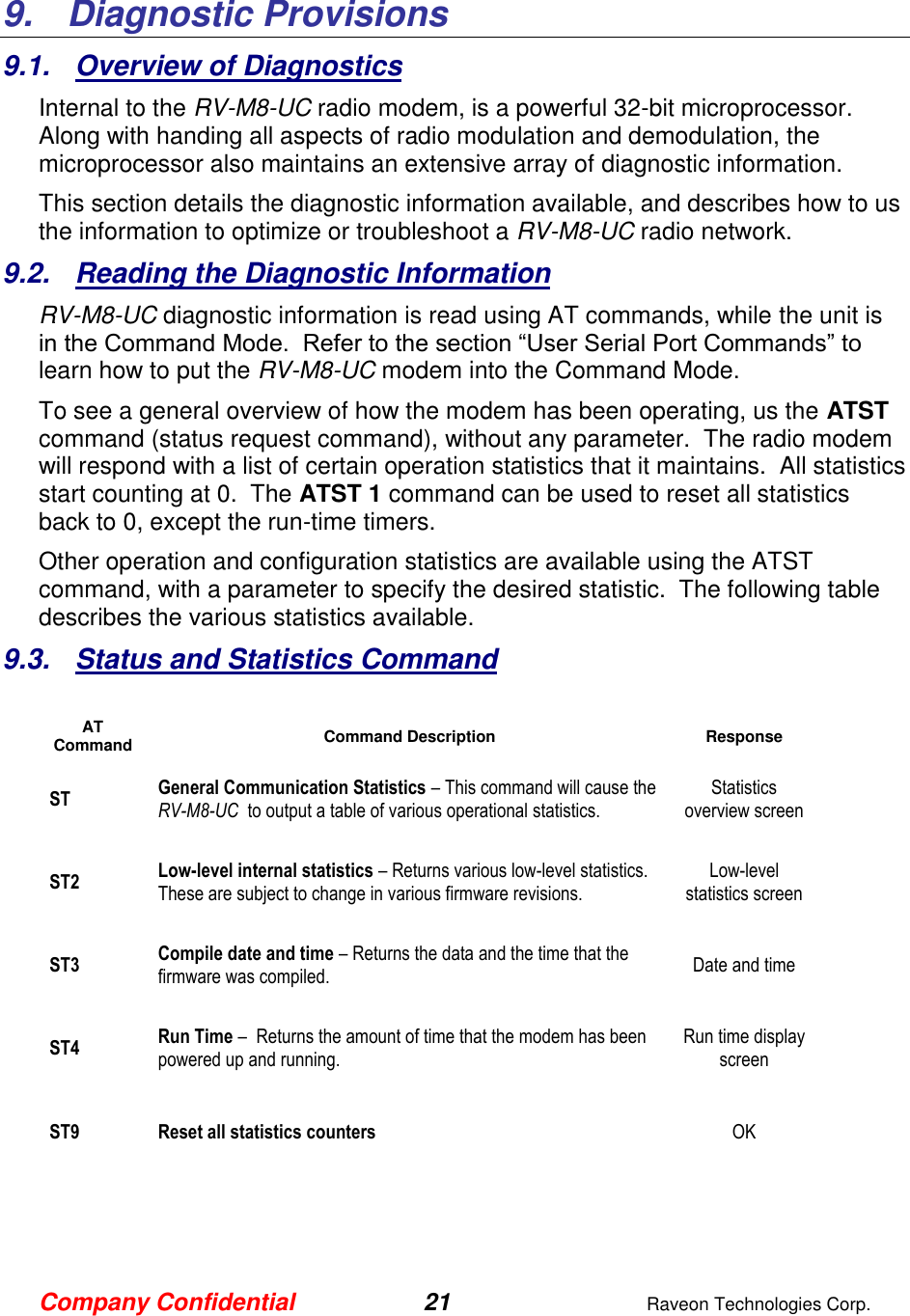
![Company Confidential 11 Raveon Technologies Corp. 4. User Serial Port Commands 4.1. Overview The serial portion the RF modem is used to send and receive data over the air, as well as to configure the RF modem. In normal operation, the user sends data into the TXD pin of the IO connector, and this data is transmitted over the air. Received data from another RF modem is output to the user via the RXD pin of the IO connector. This is the default operating condition of the RF modem. No special characters, hardware control lines, or timing is required to operate the RV-M8-UC modem. There is also a “Command Mode” used to program and configure the M8. In the Command Mode, the RV-M8-UC modem accepts commands via the serial port TxD pin. The commands can be used to change certain internal parameters of the RV-M8-UC modem as well as to read-out the current configuration and diagnostic statistics. 4.2. Command Mode The RV-M8-UC modem may be put into a “Command Mode”, by entering a sequence of three plus characters (+++). To keep the RV-M8-UC modem from unintentionally entering the Command Mode because of the +++ pattern occurring in a stream of data entering the modem, there must be a pause in the data stream before the +++ as well as a pause after the +++ is sent. If either pause is missing, the modem will not enter the command mode. Using serial communications software such as HypterTerminal, send the 3-character command sequence “+++” while observing times of silence before [BT (Silence Before Sequence) Command] and after [AT (Silence After Sequence) Command] the command characters. The default BT and AT times are 500mS. The default sequence for entering into AT Command Mode: 1. No characters sent for ½ a second. 2. Input three (3) plus characters (“+++”) within ½ of a second. 3. No characters sent for ½ a second. When the RV-M8-UC modem first enters the Command Mode, it sends the phrase Raveon RV-M8-UC (transceiver version) or Raveon M8R (receive only version) out of its serial port, and then an “OK” sequence. The “OK” sequence is a sequence of 4 characters: An “O”, “K”, <CR>, and <LF> characters (<CR> = ASCII 0D, <LF> = ASCII 0A)](https://usermanual.wiki/Raveon-Technologies-orporated/M8-UC/User-Guide-3079564-Page-11.png)