Raveon Technologies orporated M8S-UC UHF Radio Modem User Manual Usermanual
Raveon Technologies, Incorporated UHF Radio Modem Usermanual
Usermanual

Company Confidential 2 Raveon Technologies Corp.
Table of Contents
1. General Information about the RV-M8S ......................................................... 4
1.1. Congratulations! ........................................................................................................................... 4
1.2. NOTICE ....................................................................................................................................... 4
1.3. Safety / Warning Information ....................................................................................................... 4
1.4. OEM Use ..................................................................................................................................... 6
2. Overview ........................................................................................................ 7
2.1. Features ....................................................................................................................................... 7
3. Specifications ................................................................................................. 8
3.1. General ........................................................................................................................................ 8
3.2. DC Input ....................................................................................................................................... 8
3.3V Input Specifications ....................................................................................................................... 8
5.0V Input Specifications ....................................................................................................................... 8
3.3. Transmitter Specifications ............................................................................................................ 8
3.4. Receiver Specifications ................................................................................................................ 9
3.5. Interface Specifications ................................................................................................................ 9
3.6. LEDs ...........................................................................................................................................10
3.7. I/O Pinout ....................................................................................................................................10
3.8. Low Power Mode (LPM) .............................................................................................................10
4. User Serial Port Commands ........................................................................ 12
4.1. Overview .....................................................................................................................................12
4.2. Command Mode .........................................................................................................................12
4.3. Setting a Parameter ....................................................................................................................12
4.4. Reading a Parameter ..................................................................................................................13
4.5. Radio Manager ...........................................................................................................................13
4.6. CONFIG Button ...........................................................................................................................14
4.7. Exiting the Command Mode ........................................................................................................15
4.8. Password Protection ...................................................................................................................15
4.9. Command Mode Commands ......................................................................................................16
4.10. Other non-AT commands ............................................................................................................19
4.11. Factory Default Settings ..............................................................................................................20
5. Using the M8S Modem – Packet Mode........................................................ 21
5.1. Setup ..........................................................................................................................................22
5.2. Programming Channels and Frequencies ...................................................................................23
5.3. Data Transmission ......................................................................................................................23
Serial Port Baud Rate ...........................................................................................................................24
Flow Control .........................................................................................................................................24
Packet Size...........................................................................................................................................24
Key-On_Data ........................................................................................................................................24
Busy-Channel Lock Out ........................................................................................................................25
5.4. Addressing (Packetized Mode only) ............................................................................................25
Addressing Basics ................................................................................................................................25
Group Numbers ....................................................................................................................................25
Hexadecimal Numbers .........................................................................................................................26
Setting A System-Wide Address ...........................................................................................................26
Broadcast Transmissions .....................................................................................................................27
The Address Mask ................................................................................................................................27
Addressing Examples: ..........................................................................................................................28
5.5. Error Correction ..........................................................................................................................29
5.6. Store-and-Forward Repeating.....................................................................................................30
Automatic Repeater Configuration ........................................................................................................30
Manual Configuration of the Repeat Feature ........................................................................................30
6. Using the M8S Modem – Streaming Mode .................................................. 34
6.1. Streaming Mode Operation .........................................................................................................34
6.2. Baud Rate Selection ...................................................................................................................34
Company Confidential 3 Raveon Technologies Corp.
6.3. Bit Errors .....................................................................................................................................35
6.4. Carrier Detect..............................................................................................................................35
6.5. Serial Data Flow Control .............................................................................................................35
6.6. Setting the Over-The-Air Data Rate ............................................................................................36
7. Debug Related Commands .......................................................................... 38
8. M8S Diagnostic Provisions .......................................................................... 39
8.1. Overview of Diagnostics .............................................................................................................39
8.2. Reading the Diagnostic Information ............................................................................................39
8.3. Status and Statistics Command ..................................................................................................39
9. Tune-up and Alignment................................................................................ 41
9.1. Periodic Calibration .....................................................................................................................41
9.2. Calibration Commands ...............................................................................................................41
9.3. Center Frequency .......................................................................................................................42
9.4. TX Deviation ...............................................................................................................................42
9.5. TX Modulation Balance ................................................................. Error! Bookmark not defined.
9.6. RX Carrier Detect ........................................................................................................................42
10. Troubleshooting ....................................................................................... 45
Symptom: Unit will not receive.............................................................................................................45
Symptom: Unit will not transmit ...........................................................................................................45
Symptom: Receive light blinks, but no data is received .......................................................................45
Symptom: Long delay before transmitting ...........................................................................................46
Symptom: Cannot enter Command Mode ...........................................................................................46
Symptom: Modem appears dead. ........................................................................................................46
Symptom: Repeater will not repeat. .....................................................................................................46
11. Mechanical ............................................................................................... 48

Company Confidential 4 Raveon Technologies Corp.
1. General Information about the RV-M8
1.1. Congratulations!
Congratulations on your purchase of an M8S OEM radio modem – the most
advanced radio modem of its kind available today.
Please take a few minutes to read this manual carefully. The information
presented here will allow you to derive maximum performance from your radio
modem. After reading it, keep the manual handy for quick reference, in case
questions arise later on.
1.2. NOTICE
There are no user-serviceable points inside this transceiver. All service work
must be referred to your Authorized Service Center or Raveon Technologies
Service Department.
1.3. Safety / Warning Information
WARNING - DO NOT operate the RV-M8S radio modem when bystanders
are near the antenna.
Blasting Caps and Blasting Areas
To avoid possible interference with blasting operations, turn off this radio or
remove the DC power when you are near electrical blasting caps, in a
blasting area, or in areas posted: “Turn off two-way radio.” Obey all signs
and instructions.
Potentially Explosive Atmospheres
Turn off your radio prior to entering any area with a potentially explosive
atmosphere. Do not install this product for use in areas with potentially
explosive atmospheres. Do not remove, install, or charge batteries in such
areas. Sparks in a potentially explosive atmosphere can cause an explosion
or fire resulting in bodily injury or even death.
Note: The areas with potentially explosive atmospheres referred to above include fueling
areas such as below decks on boats, fuel or chemical transfer or storage facilities, areas
where the air contains chemicals or particles, such as grain, dust or metal powders, and any
other area where you would normally be advised to turn off your vehicle engine. Areas with
potentially explosive atmospheres are often but not always posted.
1.4. FCC /IC (or Regulatory Agency?) Compliance Information
a. FCC Compliance Notice
This device complies with part 15 of the FCC Rules. Operation is subject
to the following two conditions: (1) This device may not cause harmful
interference, and (2) this device must accept any interference received,
including interference that may cause undesired operation.

Company Confidential 5 Raveon Technologies Corp.
Changes or modifications not expressly approved by the party responsible
for compliance could void the user’s authority to operate the equipment.
NOTE: The manufacturer is not responsible for any radio or TV
interference caused by unauthorized modifications to this equipment.
Such modifications could void the user’s authority to operate the
equipment.
This product also complies with FCC Part 22, 90 and Part 95 Subpart J of
the FCC rules and regulations.
The Federal Communications Commission (FCC), with its action in ET
Docket 93-62, has adopted a safety standard for human exposure to
Radio Frequency (RF) electromagnetic energy emitted by FCC-certified
equipment. This product meets the uncontrolled environmental limits as
stated in OET-65C (01-01) when operated in accordance with the
operation guidelines described in this manual. Proper operation of this
radio device according to the instructions in this publication will result in
user exposure substantially below the FCC recommended limits.
This equipment generates, uses, and radiates radio frequency energy,
and if not installed and used in accordance with the instructions, may
cause harmful interference. However, there is no guarantee that
interference will not occur. If this equipment does cause interference to
radio or television reception, which can be determined by turning the
equipment off and on, the user is encouraged to correct the interference
by one of the following measures:
•Reorient or relocate the receiving antenna.
•Increase separation between the equipment and receiver.
•Connect the equipment to an outlet on a circuit different from which
the receiver is connected.
•Consult the dealer or an experienced radio/TV technician.
b. ISED RSS-Gen Notice (in English and French?)
This device complies with Industry Canada RSS for unlicensed radio
devices. Operation is permitted under both of the following conditions:
1) the device shall not cause interference;
2) the equipment must accept any interference received, even if the
interference is likely to compromise its operation
“Le présent appareil est conforme aux CNR d’Industrie Canada
applicables aux appareils radio exempts de licence. L’exploitation est
autorisée aux deux conditions suivantes :
1) l’appareil ne doit pas produire de brouillage;

Company Confidential 6 Raveon Technologies Corp.
2) l’appareil doit accepter tout brouillage radioélectrique subi, même si le
brouillage est susceptible d’en compromettre le fonctionnement”
c. ISED RF Exposure Guidance
In order to comply with FCC/ISED RF Exposure requirements, this device
must be installed to provide at least 100 cm separation from the human
body at all times.
“Afin de se conformer aux exigences d'exposition RF FCC / ISED, cet
appareil doit être installé pour fournir au moins 100 cm de séparation du
corps humain en tout temps.“ In order to comply with the FCC / ISED RF
exposure requirements, this device must be installed to provide at least
100 cm of separation from the human body at all times”
1.5. OEM Use
This radio module is for OEM use, and it is the responsibility of the OEM user
to notify the end-users of RF and electrical safety issues.
This device has no provision for external frequency programming by the
operator. Programming is done at the factory or by authorized service
technicians.

Company Confidential 7 Raveon Technologies Corp.
2. Overview
The M8S RF data radio is a rugged high-performance, high-speed narrow-
band data modem. It contains a receiver, a transmitter, and modem, creating
an easy-to-use transparent data radio link. The M8S’s user interface is
asynchronous digital data into and out of the M8S. Modem operation is
virtually transparent to the user and the configuration of the modem is via the
user serial port.
For privacy and network versatility, the M8S incorporates a 16 bit
identification code. Its protocol also uses a 16bit CRC to guarantee the
integrity of the data. Perfect for SCADA and telemetry applications, the M8S
can be used for simple point-to-point data communication applications, or for
more sophisticated point-to-multipoint, peer-to-peer, or mesh networks.
Although the M8S is the easiest to use modem on the market, its re-
programmability makes it extremely versatile. Most parameters within the
modem may be re-configured to optimize it for specialized operations,
extended range, or higher data throughput.
2.1. Features
High-speed over the air data rates.
Built-in radio transceiver with integrated modem
Easy to use. Plug-in, Turn-on, and GO. Transmit data in = Receive data out.
Lowest current draw in industry.
Wide input voltage with high-efficiency switching voltage regulator.
Integrated Packet data protocol and built-in Streaming Real-Time operation.
ARQ error correction and retransmission capability. Totally transparent to the application.
Capable of store-and-forward repeating operation.
Small sized and very rugged extruded enclosure.
16 bit addressing for up to 65,525 different unique device addresses per channel
Supports group and broadcast transmissions. Network mask allows groups of any size.
500-5000mW of RF output. Other RF power levels available upon request.
Easily configured using “AT” commands
Very fast Transmit-to-Receive turn around time.
RS-232 serial input and output. Programmable serial baud rates up to 57600.
Programmable over-the-air data rates for long-range or high-speed
Automatic key of transmitter on data.
RF carrier-detect is not required receiving. No squelch setting required.

Company Confidential 8 Raveon Technologies Corp.
3. Specifications
3.1. General
Frequency Bands: RV-M8S-UC 450-470MHz
Serial Port Baud Rates 1.2k, 2.4k, 4.8k, 9.6k, 19.2k, 38.4k, 57.6k, 115.2k
Over-the-air baud rates Narrow: 1200, 2400, 4800
Wide: 1200, 2400, 4800, 9600
Operating Mode Half-duplex
Full Spec Operating Temperature range -30°C to +60°C
Extended Temp Range { extended temp specs} -40°C to +60°C
TX-RX and RX-TX turn-around time <3mS
Wake-up time <500mS from OFF
Back-side LEDs Power , Status
RF I/O Connector SSMT
Digital signal levels 3.3V logic
Enable Input Low 400mV
Enable input High 1.40V
DC Input 10 – 30 VDC
3.2. DC Input
3.3V Input Specifications
DC Current Draw, RX mode < 100mA
DC Current Draw, TX mode 100mW RF out < 700mA {750mA}
Module disabled using pin 7 (?) < 200uA
5.0V Input Specifications
DC Current Draw, RX mode < 150mA
DC Current Draw, TX mode 100mW RF out < 400mA {500mA}
DC Current Draw, TX mode 500mW RF out < 800mA
Module disabled using pin 7 (?) <200uA
3.3. Transmitter Specifications
RF Power Output ........................... ... 500mW –5W programmable
RF Frequency Range ………………. 450-470 Mhz
Maximum Duty Cycle ............... 100% @ 100mW to 40C, 25% @600mW
Frequency Deviation .......................... ± 2.2kHz (-N) ± 3.5kHz (-W)
RF Bandwidth ..................................... 20 MHz no-tune
Occupied bandwidth ......................... 8 kHz
TX Spurious outputs .......................... < -70dBc
Occupied Bandwidth ......................... Per FCC
FCC Emissions Designator ............... 8K20F1D
Frequency Stability ............................ Better than ±1.5ppm {2.5ppm}

Company Confidential 9 Raveon Technologies Corp.
3.4. Receiver Specifications
RF Frequency Range ……………….. 450-470 Mhz
RX sensitivity (.1% BER) .................... 9600bps < -108dBm
4800bps < -116dB {-110}
1200 & 2400baud ................................ Contact Factory
RF No-tune bandwidth ..................... 20MHz
Adjacent Channel Selectivity ............ -65dB
Alternate Channel Selectivity ........... -70dB
Blocking and spurious rejection ....... -75dB
RX intermodulation rejection ........... -70dB
3.5. Interface Specifications
Serial Interface Port 20-pin male header
IO Voltage Levels 3.3V digital logic. < 1000pF load capacitance.
RX and TX data Transparent Async.
Word length 7 or 8 bits
Format N, O, or E
RF Connector MMCX

Company Confidential 10 Raveon Technologies Corp.
Electrical Inputs and Outputs
3.6. LEDs
The status LED visually show the current status of the radio.
Status LED (TX) This LED blinks red when the transmitter keys and is
putting out RF power. It blinks green upon the reception of data or RF carrier.
Power LED (PWR) This LED does a short blink, once every two seconds,
indicating to the user that the power to the modem is ON and the modem is
working. When the modem is in the command mode, this LED will blink on
and off, once per second.
3.7. I/O Pinout
The I/O connector is a 20-pin header. Pin-out and connector type to match
MaxStream 9XTend.
I/O Pin Out
Pin
#
Function
I/O
Function
1
GND
-
Ground
2
Vcc
I
DC Input
3
Carr Det
O
CD Out. High for carrier. Low for no carrier.
4
TX On
O
Pin is High when module is transmitting. Low when off,
receiving, or sleeping.
5
Data In
(TXD)
I
Transmit data input.
6
Data Out
(RXD)
O
Receive data output.
7
Enable
I
Low to shutdown the module. High to enable it.
8
Sleep
i
CPU Sleep input
9
CTS
O
Clear to send output. Indicates state of internal buffers.
10
RTS
I
RTS input for serial flow control.
11
RSSI
0
Receiver signal strength indicator
12
I
13-
20
To be determined. Raveon may use these pins for
test functions and certain data-radio features.
3.8. Low Power Mode (LPM)
The M8 modem, has the ability to be put into a low power mode (LPM). In
LPM the modem draws much less current from the DC input. In LPM, the
internal radio in the M8 is disabled, as well as certain current-consuming
hardware circuits. The ability of the M8 to go into LPM is set with a
configuration bit, using the ATSM 1 command. ATSM 1 configures the M8 to
monitor the DTR input line, and enter the LPM mode whenever DTR is
negated. If the DTR signal is asserted, the M8 modem will operate normally.
The ATSM 2 command forces the M8 modem into the low-power mode. In
the Low Power mode, the M8’s radio circuits are off, but it will still respond to
Company Confidential 11 Raveon Technologies Corp.
serial commands and it will still transmit characters over the air, albeit with
some latency as it has to power-up the radio each time it wishes to transmit.
The ATSM 0 command returns the M8 modem into the normal-operating
mode with the receiver and transmitter operational.
The factory default value for the ATSM setting is 0. When ATSM is a zero,
the M8 will not ever enter the LPM mode, and the DTR input signal is ignored.

Company Confidential 12 Raveon Technologies Corp.
4. User Serial Port Commands
4.1. Overview
The serial portion the RF modem is used to send and receive data over the
air, as well as to configure the RF modem. In normal operation, the user
sends data into the TXD pin of the IO connector, and this data is transmitted
over the air. Received data from another RF modem is output to the user via
the RXD pin of the IO connector. This is the default operating condition of the
RF modem. No special characters, hardware control lines, or timing is
required to operate the M8 modem.
There is also a “Command Mode” used to program and configure the M8. In
the Command Mode, the M8 modem accepts commands via the serial port
TxD pin. The commands can be used to change certain internal parameters
of the M8 modem as well as to read-out the current configuration and
diagnostic statistics.
4.2. Command Mode
The M8 modem may be put into a “Command Mode”, by entering a sequence
of three plus characters (+++). To keep the M8S modem from unintentionally
entering the Command Mode because of the +++ pattern occurring in a
stream of data entering the modem, there must be a pause in the data stream
before the +++ as well as a pause after the +++ is sent. If either pause is
missing, the modem will not enter the command mode.
Using serial communications software such as HypterTerminal, send the 3-
character command sequence “+++” while observing times of silence before
[BT (Silence Before Sequence) Command] and after [AT (Silence After
Sequence) Command] the command characters. The default BT and AT
times are 500mS.
The default sequence for entering into AT Command Mode:
1. No characters sent for ½ a second.
2. Input three (3) plus characters (“+++”) within ½ of a second.
3. No characters sent for ½ a second.
When the M8 modem first enters the Command Mode, it sends the phrase
“M8” out it serial port, and then an “OK” sequence. The “OK” sequence is a
sequence of 4 characters:
An “O”, “K”, <CR>, and <LF> characters (<CR> = ASCII 0D, <LF> = ASCII 0A)
4.3. Setting a Parameter
To set a parameter in the M8 modem, enter the Command Mode as
described above. Then enter the proper AT command, a space, the
parameter, and then a carriage return. For Example, to set the address of the
M8 modem to 1234, enter the following command:
ATDT 1234 <CR>.

Company Confidential 13 Raveon Technologies Corp.
Once a Parameter is changed, the modem will begin using the new
parameter and the new parameter is saved to non-volatile.
4.4. Reading a Parameter
To read the value of a particular setting, issue the command, with no
parameter. The modem will return the value followed by an “OK”. The
modem’s OK response is:
The value in ASCII decimal format.
A <CR> <LF> (<CD> = ASCII 0D, <LF> = ASCII 0A).
An “O”, “K”, <CR>, and <LF> sequence.
For example, if the user enters the command to read the M8’s modem
address and its address was 1234, the user would issue the following
command:
ATDT<cr>
and the modem will respond with:
1234 <CR> <LF> OK <CR> <LF>
To get on-line help with a command, enter the command and put a question
mark in for the parameter. For example, to see what the ATDT command is
for, type ATDT ?. The modem will respond by listing a brief description of the
command. To see a list of all commands, type HELP.
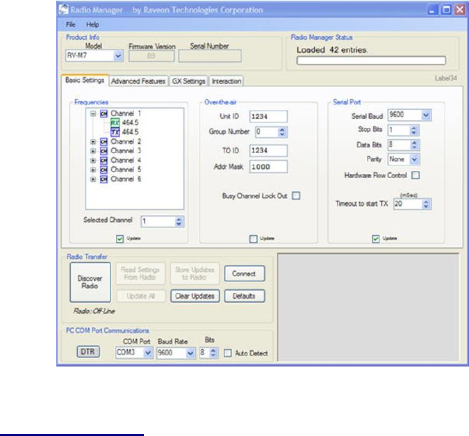
4.5. Radio Manager
Radio Manager is a Windows XP/Vista software application that is used to
configure Raveon's data radio products. It is compatible with all Raveon radio
models, and provides configuration management, as well as programming
assistance, diagnostic information, and a helpful "band scope" feature.
Radio Manager features:
Supports all Raveon Radios (M3, M5, M8 and M8 GX series)
An easy to use graphical interface
Simplified editing of a radio's configuration
Configurations may be stored to a file or retrieved from a file
Intelligent parameter verification to help configure technical parameters
On-line help
Built-in terminal mode
"Auto-Detect Radio" feature searches through possible serial port settings
Band Scope feature graphically displays on and off channel signal levels
You can use Radio Manager in lieu of learning all of the M8’s commands and
programming protocol. In most situations, it is very useful for configuring the
M8. There are certain very advanced configurations that will require manual
Company Confidential 14 Raveon Technologies Corp.
programming, but in most cases Radio Manger will be the easiest way to
setup your radio.
4.6. CONFIG Button
If certain parameters within the modem are modified in a manor that causes
the modem to cease functioning or if the user cannot enter the command
mode via the “+++” method described above, there is a small push button
internal to the M8 modem to assist in this case. This CONFIG button may be
pressed at any time, and forces the modem into a known operational state.
The CONFIG button is located inside the modem. Remove the rear cover,
exposing the two circuit boards. The button is in the front edge of the radio
module’s circuit board.
The default settings that the modem will revert to when the CONFIG button is
pressed are:
1. Serial port 9600 baud, 8 data bits 1 stop, no parity
2. ATCT setting set to 60000 (60 second time-out)
3. Serial port on the front of the unit in RS232 mode, 9600bps, N/8/1.
Even though the serial baud rate reverts to 9600 baud when the CONFIG
button is pressed and the IO port is RS232, it will revert back to the settings
programmed into the M8 modem once the Command Mode is exited.

Company Confidential 15 Raveon Technologies Corp.
Note: If the user-interface is password protected, and the Config button on
the M8 is pressed, for security reasons, the encryption phrase is
automatically erased.
4.7. Exiting the Command Mode
There are three ways to exit the command mode. They are:
1. ATCN Issuing the ATCN. The M8 radio will exit the command mode, and
begin normal operation.
2. EXIT Issuing the EXIT. The M8 radio will exit the command mode, and
begin normal operation.
3. Time Out. After a pre-set amount of time (60 seconds is the factory
default time), the modem will automatically exit the Command Mode, and
continue normal operation. Changes will not automatically be saved. This
time-out duration may be set with the ATCT command.
4.8. Password Protection
On M8 series products with firmware version C0 or higher, the user interface
may be password protected. If it is password protected, the radio will output a
“password:” prompt when entering the command mode.
When in the command mode, to enable the use of a password enter:
Password xxxx <CR>
Where xxxx is the 2-7 digit password you would like to protect the user
interface with.
To disable password protection, enter:
Password 0 <CR>
Note: If the user-interface is password protected, and the Config button on
the M8 is pressed, for security reasons, the encryption phrase is
automatically erased.

Company Confidential 16 Raveon Technologies Corp.
4.9. Command Mode Commands
AT
Command
Command Description
Parameters
Factory
Default
AK
Enable/Disable ARQ – When ARQ is enabled, this modem
will automatically send an ACK packet back to a modem that
sends it data. 0=off, 1=on.
Range: 0 – 1
0 (no AKCs
sent)
AT
Silence AFTER Sequence - Sets period of silence after the
command sequence characters in mS.
Range:0 – 1000
(mS)
500
BD
Baud Rate – Sets serial com port baud rate (bps). Over-the-
air (throughput) baud rate is set with ATR2 command.
If a PC’s serial baud rate is set higher than the fixed over-the-
air baud rate of the module, hardware handshaking may be
required.
Range: 0 – 7
0 = 1200 5= 38400
1 = 2400 6=57600
2 = 4800 7=115200
3 = 9600
4 = 19200
3
BC
Busy Channel Lock Out – Enable/disable the BCL. If
enabled, the modem will not transmit on a radio channel that
is busy (has RF on if). 0-OFF, 1=ON.
Range: 0-1
0
BT
Silence BEFORE Sequence – Sets period of silence before
the command sequence character in mS.
Range: 0-1000
mS
500
BW
Set/Read IF Bandwidth - Sets the IF bandwidth to narrow
(N) or wide (W). Narrow is for 12.5kHz channels, and wide is
for 25 or 30kHz spaced channels. This command is only
used on the VHF version of the product. The UHF does not
support w
N
N or W
CD
Carrier Detect Threshold – Read/set the carrier detect
threshold, in dBm. -113 means -113dBm. Version firmware
and higher.
-113
-120 to -60
CH
Configure Hardware Flow Control – Enable (1) or disable
(0) flow control. When enabled, the modem will monitor the
RTS line, and if it is negated, stop sending data out the serial
port. If disabled, the modem will ignore the state of RTS, and
always send out characters.
1 = Enable
0 = Disable
0
CT
Command Time Out – If no valid commands have been
received via the serial port within this time period (in
milliseconds), modem returns to normal operation mode from
Command mode. If the CONFIG button inside the M8 is
pressed, this parameter will be automatically set to 60000.
Range: 100-60000mS
60000
DCD
Invert DCD line. Use in conjunction with ATR1 to set DCD
line functionality
0-1
0
DT
Destination Address to call– Sets address of the modem to
send data to. Note, this parameter is entered in HEX format.
Each digit may be a 0,1,2,3,4,5,6,7,8,9,A,B,C,D,E,or an F.
Range: 0-FFFF
1234
E
Echo – Character echo set on (E1) or off (E0). This applies to
the Command Mode only.
Range: 0 , 1
1 (echo)
F
Display frequencies – Display all of the frequencies
programmed into all of the channel memories.
N/A
FT
Transmit Frequency – Program the transmit frequency for
this channel. Enter in Hz or in MHz. The frequency will
Range: See product data
sheet. For MURS products,
See product
data sheet.

Company Confidential 17 Raveon Technologies Corp.
automatically be saved in non-volatile memory (flash) for this
current channel number.
frequency cannot be changed.
FR
Receive Frequency – Program the receive frequency for this
channel. Enter in Hz or MHz. The frequency will
automatically be saved in non-volatile memory (flash) for this
current channel number.
Range: See product data
sheet. For MURS products,
frequency cannot be changed.
See product
data sheet.
FX
TX and RX Frequency – Program the receive and transmit
frequency for this channel. Enter in Hz or MHz. Same as
issuing an ATFR and an ATFT command. The frequency will
automatically be saved in non-volatile memory (flash) for this
current channel number.
Range: See product data
sheet.
N/A
GP
Group Number – Set/read the group number for this unit.
0 means ignore the group number. 1-255 is a group identifier.
Only M8s with the same Group Number will communicate
together.
0-255
0 (ignore
group
numbers)
HP
Channel Number – Select separate channels to minimize
interference between multiple sets of modules operating in the
same vicinity. The channel number is stored in EEPROM
memory.
Range: 1 – 6
1
HS
Show History – Show a table of listing the most recent
receptions, and the IDs that the data was sent from
No parameter
HX
Enable/Disable single-hop repeating – 0=any number of
repeats, 1 – unit will not repeat a packet that was already
repeated.
0 or 1
0 (multi-hop OK)
IO
Configure the I/O The proper hardware option must be
installed in the modem. All M8 modems support RS-232
mode.
Range: 0 – 5 0=RS232
1=Ethernet 2=RS485 dup
3=RS485 simplx 4=RS422
5=GPS
0
IC
Read Current Draw Read the current draw in mA. Accuracy
is within 20% of actual current draw.
Range: 0-9999
N/A
JF
Read/set the CTS threshold – Set the serial buffer threshold
where the CTS line is negated. By default the ATJF level is at
80% of the internal buffer size.
1 - 2000
3800
L
Enable/Disable the LEDs – 1 = LEDs always off. This
reduces some power consumption. 0 = LED operate normally.
0 or 1
0
MK
Address Mask – Configures local and global address space.
Each digit may be a 0,1,2,3,4,5,6,7,8,9,A,B,C,D,E,or F. In
most applications, this is kept at FFFF.
Range: 0000 – FFFF
FFFF
MT
Protocol Select – The over-the-air communication protocol.
0=Packetized mode, 2=Streaming data.
Range: 0-2
0
MY
Unit Address – Configures the individual; address for this unit.
Each digit may be a 0,1,2,3,4,5,6,7,8,9,A,B,C,D,E,or F. Note:
FF is interpreted as a group. See addressing section.
Range: 0000 – FFFF
1234
NB
Parity – Selects parity format. Settings 0-4 transfer 8-bits over
antenna port and generate the parity bit on the RF receiving
side.
Range: 0 – 5
0 = none
1 = Odd
2 = Even
3 = Mark (1)
4 = Space (0)
0
ND
Number of Data Bits – Set/read the number of data bits.
Range: 5 – 8
8
NS
Stop Bits – Selects the number of stop bits.
Range: 1-2
1
PE
Packet Error Display – Shows statistics to compute packet-
error rate. Displays Packets Per Minute (PPM) and a running
total.
None (display PER)
1 = reset counters
2 = Stop PER display
None
PO
RF Power Output. Set or show the RF power output setting.
Value is in percent, from 0% to 100%. Use and RF wattmeter
to confirm the power setting, and adjust the % accordingly to
obtain the desired RF power level.
0-100
100

Company Confidential 18 Raveon Technologies Corp.
R0
Symbol Peak Deviation – Set the peak FM deviation of the
transmit symbols. Note: This can be a negative number to
invert the modulation.
Range: -1000 – 1000
120**
R1
Select CD pin output signal – CD may be RF carrier detect,
or modem data detect.
Range : 0 – 3
3 = Framing
2 = Always assert CD
1 = Data CD
0 = RF CD
0
R2
Over-The-Air bit rate - This is the data rate the radio uses to
send data over the air. All RF modems in the network
must use the same over-the-air baud rate. Refer to
section 6.6 for information on how to set the OTA baud rate.
Range:
0 = 800 5 = 9600 2L
1 = 1200 6 = 19200 4L
2 = 2400 7 = 5142 2L
3 = 4800 8 = 9600 4L
4 = 8000 4L 9 = 2000 2L
3 (narrow)
R3
Serial Port Time Out – The time in milliseconds for the serial
port to time out. When data is entering the serial port, and
this amo0unt of time passes with no more data, the M8 will
begin to transmit the data over the air.
Range: 1 – 999
20
20mS is the
default.
R5
Preamble length – The number of bytes to send over-the-air
in the pre-amble.
Range: 3 – 255
5**
(Varies based on
data rate and
radio type. 7
typical)
R8
Frequency Offset. Used to set the radio on the center of the
radio channel.
Range: -500 to +500
0**
RB
Number of retries. If this modem does not get an ACK
back when it sends data, this is the number of times it will re-
transmit the packet and wait for an ACK. 0=disabled feature.
Range: 0-99
0
(ACKs are not
used)
RF
RF Carrier Required – When enabled, there must be RF
energy on the channel for the modem to output data.
Streaming data mode only. 1-RF required. 0=ignore RF
energy when receiving.
Range: 0, 1
0 (no RF
required)
RQ
Receiver Signal Level – Reads the Receiver Signal
strength this instant, and returns the level in dBm.
Range: -40 to –130 (dBm)
-
RS
RSSI (Receive Signal Strength Indicator) – Returns the
signal level of last received packet. The reading is in dBm.
Usable for relative comparison of signals, but absolute value
is within10dB at -90dBm.
No parameters. Returns a
number : -50 to –140
(dBm) varies by model.
None
RV
Disable Remote Access – When enabled (set to a 0), the
modem will respond to over-the-air RPR requests, Pings, and
over-the-air commands. Default is OFF (1).
0 = Remote Access on
1 = Remote Access off
1
S120
Data Framing Pre-time (mS) 255 is data framing off. Use
with ATR1 3. See section 9.6
0-255
255
S121
Data Framing Post-time (mS) 255 is data framing off. Use
with ATR1 3. See section 9.6
0-255
255
SL
Serial Number – Reads and returns a unique serial number
for thjs unit.
Read Only
1 - 999999999
unique
SH
Show – Display the configuration of the modem. This will
return a page of ASCII characters, showing the main
configuration parameters.
none
None
SM
LPM Operation Enable – When set to 1, the DTR input line
controls the M8’s low-power operation. When set to 0, the
M8 will not go into LPM, regardless of the state of the DTR
pin. When set to 2, the modem is forced into a low-power
Range: 0, 1, 2
0

Company Confidential 19 Raveon Technologies Corp.
mode, disabling the receiver.
ST
Statistics – Show the unit’s operational statistics. See
Statistics section of user manual.
0, 1,2, 3, 4, or 5
None
TD
Transmit Test Data – When issued, the modem will begin
transmitting data. The type of data sent is set in the
parameter. Entering a <CR> will terminate the transmission.
0 = Go back to normal
1 = Random
3 = 1010… at ¼ baud rate
4 = TX all 0s
5 = TX all 1s
6 = Test Points ON
7 = Transmit CW
8 = Transmit 1010101…
TE
Read product temperature – Read the internal temperature
of the unit’s circuit board in degrees Celsius.
-40 to +99
-
TT
Max Packet Size – Set the maximum number of bytes in an
over-the-air packet.
1 - 512
80
VB
Read DC input Voltage– Returns the DC input voltage
reading, in mV (12500 = 12.5VDC input).
None
none
VR
Firmware Version – Returns firmware version currently
loaded on the module.
Read Only, 3
characters
none
Xn
Show or Configure the Repeat Table – Set the addresses
that this unit will store-and-forward data to/from. n = 1, 2, 3, or
4 designating the entry in the table to show or edit..
Four parameters
aaaa bbbb cccc dddd where
aaaa=Source Address
bbbb = S.A. Mask
cccc = Destination Address
dddd = D.A. Mask
XR
Enable/Disable Store and Forward Repeating – 0=disabled,
1 – enabled.
0 or 1
0 (Off)
XT
Read/set repeater delay – Read or set the repeater delay.
This is the time between receiving a data packet, and the time
the repeater will re-send it.
&F
Restore Factory – Restore the factory default values. This
command will not erase the calibration values. After this
command executes, the modem will still be in the CONFIG
mode.
none
** indicates values that are calibrated in the factory and are unit-specific. If the “Radio
Type” is changed, these will need to be re-calibrated.
4.10. Other non-AT commands
BAND
Read the Band – Reads the frequency band of the radio.
First parameter is the text version (UA, UC, VB, …),
second parameter is the lower limit, and the third
parameter is the upper limit in MHz. Use to read the band
that the radio is tuned to cover.
None
-
CONFIG
Display the M8’s configuration.
0, 1, or 2
-
MODEL
Read Model number. Read the model number.
None
-
PING
Ping another modem. Format is PING xxxx, where xxxx
is the ID of the modem to ping. If remote access is
enabled on xxxx, it will respond.
XXXX
-
REPEAT
Turn Repeater feature on/off. If 1, a quick way to
enable repeating all packets. I f 0, disables the repeat
feature.
0 (off) or 1 (on)
0
RPR
Remote Procedure Request. Used to request execution
of a command on a remote mode (over the air). See M8
System Protocol manual for information on using this
feature.
SHOW
Show/display an overview of the radio’s
configuration.
None
-

Company Confidential 20 Raveon Technologies Corp.
4.11. Factory Default Settings
For the UHF M8S, model RV-MS8-Ux, the main factory defaults are:
Channel 1 (-UC model) ................................... 464.500 MHz
Channel 1 (-UA model) ................................... 413.100 MHz
Over-the-air baud rate: ...................................... 4800 baud, 2-level
Serial port .......................................................... 9600baud, N/8/1
Hardware flow control ....................................... Off
RF Power Output .............................................. 20% (1W)
Channel number selected ................................. 1
ID (ATMY) ......................................................... 1234

Company Confidential 21 Raveon Technologies Corp.
5. Using the M8S Modem – Packet Mode
This section describes the operation of the when it is in the Packet Mode of
operation. Packet Mode is the factory-default operating mode. It is the easiest
and most reliable mode of operation for a modem. Note: The configuration of
the M8S is done when the M8S is in the “Command Mode”. Refer to Section 1
on page 12 for details on all of the available commands and programmable
features.
In Packet Mode, all transmissions are sent in bursts or packets, and contain
address, error detection, and error correction information. Date enters the M8
modem’s serial I/O port, and is stored in a buffer within the modem until it is
ready to be transmitted. Packetized operation has these advantages over non-
packet modems:
Packet Mode Advantages
1. Error Detection The modem uses a 16-bit CRC at the end of every packet
of data. The CRC is used to check the data for errors, and if there are any
errors, the data will not be passed onto the user.
2. Error Correction Automatic error correction may be used. M8 modems
incorporate an optional ARQ method to re-transmit packets with error, to
ensure the user’s data is delivered error-free.
3. Addressing Packetized operation allows for a more versatile network
architecture, with source, destination, and network addresses. M8 uses a 16-
bit address to identify data packets.
4. No Dribble Data Even in the presence of noise, the M8 modem will not
output extra data or have random bit errors. Modems without packet
operation generally do not work well with weak noisy signals.
5. Transparent Operation Because of the high-reliability and error-free
operation the Packet Mode offers the user, most user applications will
seamlessly work using the M8 in its Packet Mode.
6. Repeatable and Routable. M8 packets are structured so that they may be
repeated using a store-and-forward repeater, and/or routed using specialized
hardware.
Streaming Mode Advantages
1. Low Latency The transmitter will key-up immediately upon the user’s first
byte of data entering the modem. Packetized operation waits until a packet
has been loaded before keying. (Although high serial-port data rates can
minimize this packet latency to a negligible level).
2. Data with Errors The M8 will continue to receive data, down into the noise-
floor of the radio. If the channel is noisy or the signal is weak, there may be
bit-errors in the data, or the M8 may output additional noise data. User
Company Confidential 22 Raveon Technologies Corp.
applications must (and often do), take this into account, and thus can operate
with weaker signals and have longer communication range.
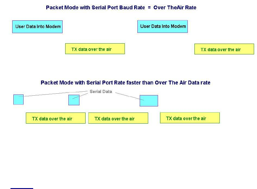
Figure 1 (Packet Mode of Operation)
For operation of the modem in the streaming data, non-packetized mode, see the
section Streaming Mode on page 32. The Packet or Streaming operation is
configured using the ATMT command, with Packet Mode being the factory
default.
5.1. Setup
1. Connect a DC power source to the DC IN connection on the front of the
modem.
2. Connect a good quality antenna, cut to the operating frequency, to the BNC
connector on the front of the modem. Use a good antenna, and place is at
high-above obstructions as possible.
3. Connect a computer terminal, or PC computer running HyperTerminal, to the
9-pin I/O connector. The factory default serial ports settings are 9600 bps, 8
data bits, 1 stop, no parity.
4. Program the modem’s operating frequency to your desired operating
frequency. This is done with the ATFX xxx.xxxxx command. See the section
“Serial Port Commands” for information describing the various parameters
that may be modified in the modem. In most applications, the default settings
from the factory will work fine.
5. Using the AT commands, change any of the default operating parameters that
must be modified. From the factory, the modems are configured and shipped
ready-to-use. Out of the box, they will communicate on the default radio

Company Confidential 23 Raveon Technologies Corp.
channel using the factory defaults. In general, the parameters you may want
to modify will be:
ATFX Frequency for this channel. Set to your frequency.
ATBD Serial port baud rate
ATMY The ID of this unit. Default is 1234.
ATMK The network address mask. Default is FFFF.
ATDT The address of the unit this modem will talk to. Default is 1234.
6. Connect your serial data device to the 9-pin connector on the front of the
modem.
The radio is now ready to use. Any serial data going into the modem will be
transmitted over the air, and any data received over the air will be sent out the
serial port.
Remember, that from the factory, all M8 modems are configured to simply work.
Plug in power and connect to the serial port at 9600 baud, and the modems will
communicate on the default channel. Change the channel frequency to your
specific frequency, and they will be ready to work on your channel.
5.2. Programming Channels and Frequencies
The M8 modem has memory for up to 6 channels. A channel is a pair of
frequencies, one for transmit and one for receive. They may be different or they
may be the same. You may program any valid frequency into any channel
number. To program a channel, perform the following steps.
1. Change to the channel you wish to program, using the ATHP x command,
where x is the channel number.
2. Program the frequency for this channel x, using the ATFT, ATFR, or ATFX
command. Note that the frequency my be entered in MHz as long as you
use a decimal point. For Example, enter ATFX 450.1 to set the channel
frequency to 450.100MHz. Alternately, you may enter the frequency in hertz
by entering ATFX 450100000. You must enter all of the zeros if you enter the
frequency in hertz.
3. Review the frequency setting with the ATFT, ATFR, or ATFX command. To
see a list of all of the channels , enter ATF.
4. To change the radio channel, use the ATHP x command while the modem is
in the command mode.
5.3. Data Transmission
To transmit data, send one or more bytes of data into the serial port of the
modem. When a full packet of data has been collected into the internal buffer of
the modem, or when there is a pause in the data, the modem will automatically
key its transmitter, and send the data over the air.

Company Confidential 24 Raveon Technologies Corp.
Serial Port Baud Rate
While the modem is transmitting, the user may continue to send more data into
the M8. Because the buffers in the M8 are full-duplex, the serial port data rate
and the over-the-air data rates are independent. The serial port baud-rates may
be set slow to accommodate legacy equipment, or set at high-speed to minimize
latency. The over-the-air data rate us usually 4800 baud for narrow-band
channels, and 9600 baud for wide-band, although faster or slower rates may be
used.
In Packet Mode, selection of the serial port baud-rate is important. As shown
above, if the serial port baud-rate is the same as the over-the-air baud rate and
the packets are short, the channel utilization is only about 50%. But, if the serial
port baud rate is set much higher, say 2-8X the over-the air rate, the channel
utilization becomes near 100%.
Because the M8 can handle serial-port data rate far in excess of the over-the-air
rate, the efficiency of the M8 in Packet Mode is approximately the same as other
brand modems that cannot operate in a Packet Mode — with the added benefit
or ARQ, error-free data, and addressing.
Note that many Windows applications which use the serial port, such as
HyperTerminal, put large gaps between the bytes of data they send out the serial
port. If an application is not getting the desired throughput, verify that it is not an
artifact of the Operating System or the computer.
Flow Control
If large amounts of data will be sent with the M8, it may be possible to overflow
the internal data buffer. To ensure the transmit buffer does not overflow, enable
and use hardware flow control. Hardware flow control is enabled with the ATCH
1 command. Note that the M8 modem will always indicate the status of its
internal buffer using the CTS signal on the DB-9 serial connector. When CTS is
negated, the internal buffers are more than 80% full. When it is asserted and it is
“Clear to Send”, the buffers are less than 80% full.
You can modify this CTS threshold with the ATJF xx command. If you would like
CTS negated when there is 1or more bytes in the M8’s buffers, set ATJF to 1
(ATJF 1).
Packet Size
The over-the-air packet size may be set with the ATTT xx command. Once the
modem receives one full packet of data into via the serial port, it will
automatically key the transmitter and send the data. Factory default is 80 bytes.
The M8 will also automatically send all of the data in its buffer when there is a
pause in the incoming data stream, regardless of the ATTT setting.
Key-On_Data
When serial data is entering the M8’s RS-232 port, the M8 looks for pauses in
the data as indication that it is time to send a packet of data over the air. The

Company Confidential 25 Raveon Technologies Corp.
factory default duration of the pause it looks for is 20mS, but the user may
change this to over values using the ATR3 xxx command, where xxx is in
milliseconds. ATR3 2 (2mS) is a good setting if you are configuring the M8 for
use in a polled SCADA system.
Busy-Channel Lock Out
If your system operation require the M8 modem to monitor-before-transmit, of if
you do not want the M8 to transmit on a channel that is busy, you can enable
“Busy-Channel-Lockout”, using the ATBC 1 command. ATBC 0 disables BCL,
and thus the modem will transmit whenever it has data to send out. The factory-
default is BCL disabled. Use caution when enabling it, as a CW interferer, PC
with poor shielding, or some other source of RF can stop the modem from
transmitting. The threshold where the M8 senses RF carrier, and determines
that the channel is busy is set by the ATRA command. This is factory calibrated
to an equivalent RF level of approximately -110dBm.
5.4. Addressing (Packetized Mode only)
Addressing Basics
One of the more powerful aspects of the M8 modem is its addressing scheme.
Incorporating addressing in the modem allows multiple radio systems on the
same frequency to co-exist, and not interfere with each other. Also, some user
application cannot tolerate receiving data that was not intended for it, and by
setting the addresses in the modems properly, the system can be configured to
allow reception of only data intended for the recipient.
If addressing is not needed or desired, it can be turned off so that all modems
receive data from all other modems, and all modems can talk to all other
modems.
Each M8 contains a 16 bit address, called its Unit Address, and is represented as
a 4 digit hexadecimal number. M8 address may be any number between 0000
and FFFF, which is effectively 65,535 different addresses. Every M8 has a Unit
Address programmed into it, as well as the ID of the unit it will send data to. The
Unit Address is programmed with the ATMY xxxx command, and the Unit
Address of the destination modem (the Destination Address) is configured with
the ATDT xxxx command.
The defaults UNIT ID in al M8 modems is 1234, and 1234 is the default for the
destination ID. An Address Mask is used to select which digits of the address will
be used to determine if a particular reception was intended for the M8 modem.
The default Address Mask is FFFF, which means all digits will be used. With
these settings, by default all M8s will talk to and hear all other M8 radio modems.
Group Numbers
By default the M8’s Group Number is 0. Group 0 means ignore the group
numbering. The Group Number is set with the ATGP xx command, where xx is
the group number. ATGP 0 disables group numbering and is the default way the
M8 radio modem works. If the Group Number is set to any non-zero number
Company Confidential 26 Raveon Technologies Corp.
from 1-255, then the group feature is enabled, and the group number will be the
group specified in the ATGP command. When enabled, the M8 will only
communicate with other M8s that have the same Group Number.
Hexadecimal Numbers
For those not familiar with hexadecimal numbers, a hexadecimal digit represents
a 4-bit binary pattern. There are 16 possible values
(0,1,2,3,4,5,6,7,8,9,A,B,C,D,E,and F). These 16 values represent 4 bits of
information, thus 4 hexadecimal digits can represent 16 bits of information. The
hexadecimal numbers represent 4 bit data in the following way:
Hexadecimal Table
Hex #
Binary
Hex #
Binary
Hex #
Binary
Hex #
Binary
0
0000
5
0100
8
1000
C
1100
1
0001
6
0101
9
1001
D
1101
2
0010
7
0110
A
1010
E
1110
3
0011
8
0111
B
1011
F
1111
When communicating over the air, M8 modems transmit their Unit Address and
the Destination Address along with the data. Receiving modems check the
received Destination Address, and see if it matches their Unit Address. If it does
match, the receiving modem outputs the data it received via its serial port. If it
does not match, the receiving modem discards the data, and does not send it out
the serial port.
Setting A System-Wide Address
If individual addressing is not needed in your system, there are two ways to
ensure it is not used. One way is to set all modems in the system with the same
Unit Address and Destination Address. From the factory, these are both set to
1234, and thus, all modems can communicate with all other modems, using the
address 1234. The advantage of using this system-wide address, is that if there
are other M8 modems on the channel, but in some other system, they probably
will not have the same Unit Address, and thus will not interfere with your system.
To reduce the possibility of data cross-talk, the system implementer may wish to
use a different system-wide address for the Unit Address instead of 1234. There
are over 65,000 addresses available.
An alternate way to disable addressing altogether, is set the Address Mask to
0000 (ATMK 0000 command). This tells the M8 to ignore the address, and
receive every transmission. The disadvantage to this method is the adjacent-
system problem. If there is another M8 system on the same channel, all
modems with the 0000 mask will receive them also.
A good idea is to start numbering all of your M8 with a Unit Address of 0001,
0002, 0003, etc… Set the address Mask to F000. This will let all M8s with ID’s
0001-0999 talk to each other. If you want a separate group, start numbering
them 1000, 1001, 1002, etc… Then the 1000 series group will only hear 1000
series M8’s and the units that have IDs starting with 0xxx will only hear other
radios with IDs that start with 0xxx.

Company Confidential 27 Raveon Technologies Corp.
Broadcast Transmissions
The double FF is used to identify a broadcast packet. A transmission with a two
digit FF in the first two positions of the destination ID, or in the last two positions
of the destination ID, will be interpreted as a broadcast, and any modem with an
ID that matches the two non-FF digits will receive the data. For example,
sending data with a destination ID of 12FF will be received by any modem with a
unit ID 1200 through 12FF. Sending data with a destination ID of FF34 will be
received by any modem with a unit ID of 0034 through FF34.
The Address Mask
The reason to use hexadecimal digits to represent the unit address, is that along
with the Unit Address programmed into the M8, there is an “Address Mask”
programmed into it. The default mask is FFFF. The address mask is used to
determine if a particular data transmission should be received by the modem.
For most applications, where one modem talks to one modem, or where all
modems in the system communicate with all other modems in the system, the
Address Mask should stay set to FFFF.
Only in systems where some modems should only talk to certain other modems,
might you want to change the address mask. Whenever data is received over
the air, the Destination Address of the transmission is logically “ANDed” with the
Address Mask in the receiving modem. This is the Effective Destination Address.
The receiving M8 also ANDs its own Unit Address with its Address Mask. The
result is the Effective Unit Address. The Effective Unit Address is compared to
the Effective Destination Address, and if the two are identical, the data will be
received.
Note: Logically 1 AND 1 = 1, 0 AND 0 = 0, 1 AND 0 = 0, 0 AND 1 = 0
Company Confidential 28 Raveon Technologies Corp.
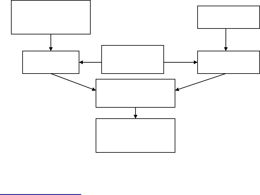
` Figure 2 (Address Filtering)
One effect of this is that an address mask of 0000 will cause the M8 modem to
received any data from any unit that transmits. The Destination Address will
effectively be ignored if the mask is set to 0000.
Addressing Examples:
Example 1 (default configuration)
Sending Destination Address = 1234
Receiving Unit Address = 1234
Receiving Unit’s Address Mask = FFFF
Result: Unit will receive the data, because the addresses identically match. When the
addresses are identical, the value of the mask is not important.
Notes: This is the default configuration. All units have address 1234, and all modems will talk
to all other modems with address 1234.
Example 2 (a configuration that won’t work)
Sending to Destination Address = 1236
Receiving Unit Address = 1234
Receiving Unit’s Address Mask = FFFF
Result: No data will be received, because the address do not match, and the address mask
of FFFF requires that all digits in the address match. .
Example 3 (able to receive a data from a group, 1230 – 123F)
Sending to Destination Address = 1236
Receiving M8 Unit Address = 1234
Receiving M8 Address Mask = FFF0
M8 receives data
over-the-air to
Destination Address
xxxx
M8 has Unit
Address yyyy
M8 has
Address Mask
zzzz
“AND” them
together
Compare the two
results from these
two ANDs
“AND” them
together
Output the data via
serial port if the two
results were
identical

Company Confidential 29 Raveon Technologies Corp.
Result: Data will be received. 1236 ANDed with FFF0 is 1230. 1234 ANDed with FFF0 is
1230. The results of the ANDing match, and thus the data will be received.
Example 4 (able to receive from a group, xx34 where xx is any two digits)
Sending Destination Address = 2234
Receiving M8’s Unit Address = 1234
Receiving M8’s Address Mask = 00FF
Result: Data will be received. 2234 AND 00FF equals 0034. 1234 AND 00FF equals 0034,
therefore they match. The results of the ANDing match, and thus the data will be received.
5.5. Error Correction
The M8 modem has a built-in error correction mode, commonly referred to as
Automatic Repeat request (ARQ). It works by checking each reception for errors,
and if the data is OK, it sends a short “ACK” packet back over the air telling the
sending station the data was OK.
The M8 modem uses a traditional Carrier Sense Multiple-Access (CSMA)
algorithm with randomized re-try time slots to determine when to re-transmit
packets that must be re-sent. The duration between re-tries increases as the
number of attempts increases.
If received data has an error in it or if the receiving modem does not get the data
due to interference, the receiving modem does not send the ACK back, and the
sending station will automatically re-send the data. There are two aspects to
configuring ARQ:
a. Enable the ARQ mode in the modem to allow it to transmit ACKs
(ATAK 1 command). This command enables the modem to transmit
ACK packets.
b. Configure the number of retries the modem should attempt if an ACK
packet is not received back when it sends data (ATRB xx command).
For example, if you set ATRB to 5 with the ATRB 5 command, the
modem will wait for an ACK whenever it sends data. If it receives and
ACK back from the modem that it sent data to, it will do nothing more.
But if it does not receive an ACK, it will resend the same data, trying up
to 5 more times.
The factory default condition is not to send or require ACK packets, so if you wish
to use this mode, program the M8 to transmit ACKs with the ATAK 1 command.
This will cause the modem to send an ACK anytime it receives data from another
modem. Note: If the destination address was a broadcast (FFFF, FFxx, or
xxFF), it will not wait for an ACK.
The number of times it retries to send data that does not get through (does not
get an ACK) is up to the user, but a number of 5 is usually a good compromise.
If after 5 times, the data does not get through, then there probably is something
seriously wrong with the channel or system.
The retried-transmissions are randomly spaced at intervals between
approximately 200mS and 400mS, increasing by 50mS for each attempted

Company Confidential 30 Raveon Technologies Corp.
transmission. Once the modem has sent its data the number of times the user
specified in the ATRB xx command, the data is discarded, and the modem will
continue to operate as normal.
It is very important that if one modem is configured to send ACK packets (ATAK
1) that all other modems communicating with it are also set to expect ACK
packets using the ATRB xx command.
To disable ARQ (the default condition of the modem), disable ARQ with the
ATAK 0 and set retries to zero with the ATRB 0 command.
5.6. Store-and-Forward Repeating
The M8 modem has a built-in wireless repeater. Each M8 is capable of not only
sending and receiving data from/to its serial port, but also re-transmitting data
packets it receives over-the-air data.
Automatic Repeater Configuration
The easiest way to enable store-and-forward repeating is the use the REPEAT 1
command. REPEAT 1 will turn on the store-and-forward feature, and configure it
to repeat all packets the radio can hear on the air. REPEAT 0 disables store-
and-forward repeating.
It is highly recommended that you use this method to configure your M8 as a
repeater.
Important: The Unit ID of the repeater must be unique in the system. No other
radio modem in the system can have the ID of the repeater.
Manual Configuration of the Repeat Feature
There is a sophisticated packet repeating algorithm in the M8, and it may be
manually configured for more complex repeating scenarios. In most cases this is
not needed. Simply use the REPEAT 1 command. But, if you do not wish the
repeater to repeat all packets, you may manually configure the Repeater Table
within the M8. The Repeater Table is a table of IDs that the M8 should repeat. It
contains a range of IDs and a mask. There may be up to 4 entries in the
Repeater Table, each with a different range of IDs that should be repeated.
Important: The Unit ID of the repeater must be unique in the system. No other
radio modem in the system can have the ID of the repeater.
Data is transmitted over-the-air in bursts called packets, and each packet has the
Unit ID of the M8 that sent the data and the Destination ID of the unit that the
data is intended for.
Company Confidential 31 Raveon Technologies Corp.
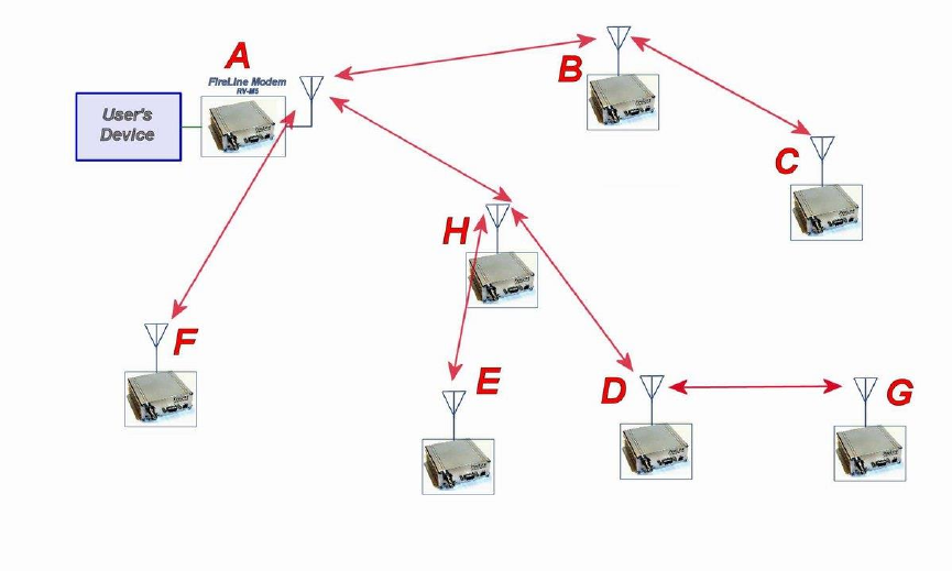
Figure 3 Overview of Repeater Operation
In the example shown in Figure 3 above, M8 A is will communicate with all other
modems in the system. It can directly communicate with B, H, and F. Because
of propagation limits, it cannot communicate reliable to E, D, C, and G.
To solve this problem, some of the M8 modems are configured as repeaters.
The still are able to send and receive data, but they also will repeat data out to
the modems that are out of range of M8 A.
H is configured to repeat all messages to/from E, D, and G. B is configured to
repeat all messages to/from C, and D is configured to repeat all messages
to/from G.
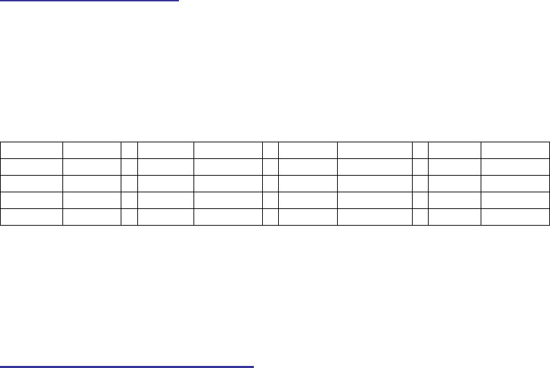
The following table illustrates one possible way the M8s could be programmed to
accomplish this type of system.

Company Confidential 32 Raveon Technologies Corp.
M8
Unit ID
(ATMY)
Destination
(ATDT)
Network
Mask
(ATMK)
Repeat
Source
Repeat
Source
Mask
Repeat
Destination
Repeat
Destination
Mask
Addresses programmed into unit
Repeater table programmed into unit
A
1000
1000
FF00
-
-
-
-
B
1010
1000
FF00
1020
FFFF
1000
FFFF
1000
FFFF
1000
FFFF
C
1020
1000
FF00
-
-
-
-
D
1030
1000
FF00
1031
FFFF
1000
FFFF
1000
FFFF
1000
FFFF
E
1032
1000
FF00
-
-
-
-
F
1021
1000
FF00
-
-
-
-
G
1031
1000
FF00
-
-
-
-
H
1022
1000
FF00
1030
FFFF
1000
FFFF
1000
FFF0
1000
FFFF
Store-and-forward repeating is manually enabled with the ATXR command.
ATXR 1 enables repeating. ATXR 0 disables it. Unlike the REPEAT x command
which configures the repeater table to repeat all packets, the ATXR 1 enables
the feature but does not configure the Repeater Table.
The Repeat Source, Repeat Source Mask, and the Repeat Destination are
programmed into a Repeater Table in the M8. The ATX command is used to
program the Repeater Table. The Repeater Table may have up to 4 entries.
For example, M8 B in the above example will have two entries in its Repeater
Table. The command to set the two entries is:
ATX1 1020 FFFF 1000 FFFF
ARX2 1000 FFFF 1000 FFFF
The first command above sets the Repeat Source to 1020 and the Repeat
Destination to 1000, both with a Mask of FFFF. The FFFF mask means all digits
of the source and destination are used to determine if the transmission should be
repeated. All packets from units with MYID 1020 (C) sent to 1000 will be
repeated by this unit. It will not repeat messages from D, E, F, G, or H because
their Unit IDs are not in the Repeat Source repeater table.
The second command above sets the Repeat Source to 1000 and the Repeat
Destination to 1000, both with a Mask of FFFF. The FFFF mask means all digits
of the source and destination are used to determine if the transmission should be
repeated. All packets from units with MYID 1000 (A)sent 1000 will be repeated
by this unit. In other words, all transmissions from A will be repeated by B.
To view the Repeater Table, use the ATX command, with no parameter. To view
a single entry in the table, use the ATXn, where n=1, 2, 3, or 4.

Company Confidential 33 Raveon Technologies Corp.
To delete an entry in the table so it has no effect on the operation, set the fields
to 0. For example, to disable entry 1, use the ATX1 0 0 0 0 command.
There can be an issue with regard to store-and-forward repeating and busy
channels, particularly on polled systems. Raveon’s M8 wireless modem has a
number of provisions in it to make store-and-forward repeating work smoothly.
For example, in the diagram above, assume A is the master station, and C is a
remote station being polled. When the store-and-forward repeater B sees a
packet it should repeat, immediately upon reception of the packet, it keys its
transmitter and repeats the packet. The scenario that can cause problems is if
the end receiving station C actually heard the original transmission from A. In a
polled scenario, the end station C will typically then respond to the poll, and want
to transmit. Station C’s transmission can happen at the same time as the
repeater B is trying to repeat the original transmission.
This contention can be reduced/eliminated in the following ways:
1. Turn busy-channel lock-out on (ATBC 1) on all modems. This stops them from transmitting
on a busy channel (stops them from transmitting when the repeater is transmitting).
2. Set the serial port baud-rate on the end-stations to be fairly slow (ATBD x). Thus, when they
receive a poll request, there is a delay as they send data in/out of their serial ports, and
during this delay, the repeater can do its thing.
3. Increase the serial port time-out value from 20mS to say 250mS (ATR3 250). Then, when
the polled station responds, there is a 250mS delay before the end station’s data gets sent
out over the air. This gives a little gap for the repeater to use for repeating messages.
4. Any combination of 1-3.
M8S radio modems will not repeat or receive duplicate versions of the same data
packet. If two repeaters are used in the same system, each will repeat a
transmission only one time, even if they are within communication range of each
other. A repeater will not repeat a transmission if it was the originator of the
transmission. If another M8 in the system has the same ID as the repeater, the
repeater will not repeat data from that particular unit. The repeater’s ID must be
unique in the system.
If a M8S is configured as a repeater, and is also used to send and receive data, it
will not repeat any transmission that it originated. M8 check the ID of the station
that originated the transmission to determine if the message should be repeated.
If the transmission was originated by a station with the same Unit ID as the Unit
ID in the receiving station, the data will not be repeated. This is why it is
important to have a different ID for each M8S modem in a network that uses
repeaters.
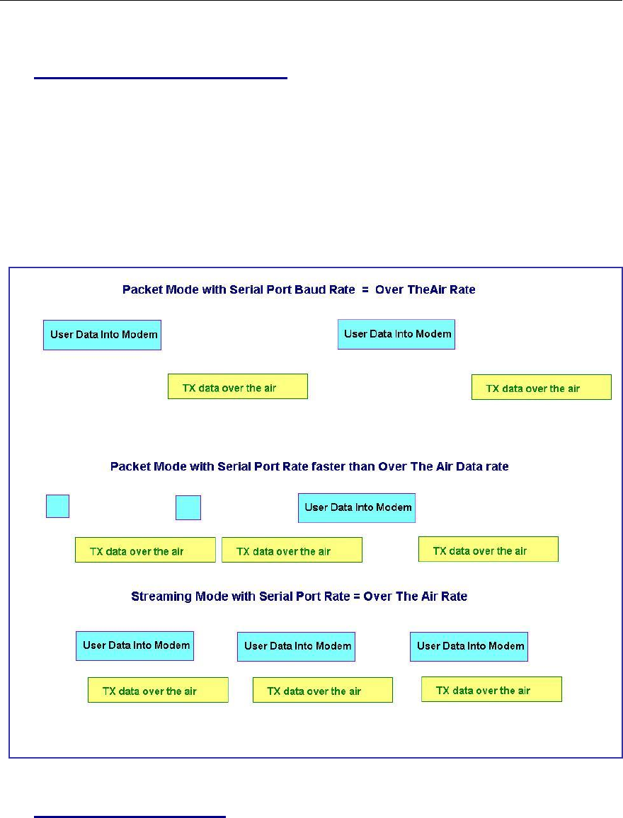
Company Confidential 34 Raveon Technologies Corp.
6. Using the M8S Modem – Streaming Mode
This section describes the operation of the Streaming Mode of operation. This
mode is selected with the command ATMT 2.
6.1. Streaming Mode Operation
In Streaming Mode, radio transmissions will begin whenever data enters the
mode, and the transmission will continue as long as there is data to send. The
transmitter will automatically key when data enters the modem, and there is no
need to assert any control lines. It will automatically de-key when there is no
more data to send.
Figure 3 illustrates the difference between the Packet Mode and the Streaming
Mode of operation.
` Figure 4 (Streaming Mode of Operation)
.
6.2. Baud Rate Selection
In Streaming Mode, the user data may still enter the modem at any baud rate, as
set with the ATBD x command. The M8 modem will buffer the data and send it

Company Confidential 35 Raveon Technologies Corp.
out over the air in the same order as it enters the modem. When the buffer is
empty and there is no more data coming into the modem, it will automatically de-
key the radio and go back into the receive mode. The M8 modem will send a
hidden end-of-message signal to the receiving modem, thus avoiding any extra
data bytes “dribble bytes” from coming out of the user serial port. When the
modem is operating with very weak signals, the end-of-message signal may be
obscured, and missed by the receiving M8. In this case, additional noise bytes
may come out of the user serial port.
While receiving, the modem will also output the receive data out the serial port at
the rate set by the ATBD command. If the serial port baud-rate is slower than
the over-the-air rate, an internal buffer in the M8 modem will hold the data as it is
sent out the serial port.
6.3. Bit Errors
Unlike Packet Mode operation, there is no error-detection nor error-correction in
the Streaming Mode, so user data may contain bit errors. The user’s application
must be able to handle these errors or additional bytes of noise data.
If the application that is using the M8 cannot tolerate have erroneous data when
the channel is noisy, the modem should be operated in the Packet Mode instead
of Streaming mode ( In Packet Mode, data is always first checked for bit-errors,
and never outputted if it detects any errors).
The end of a transmission is detected by the receiving modem by the presence
of a special end-of-message signal. Transmitting M8s automatically put the end-
of-message signal out after the user’s data has been transmitted. If the receiving
modem does not receive this signal (due to noise or interference), the receiving
modem may continue to output some more data, until it detects that the RF
carrier is gone, or the received signal is actually noise. This may take a byte or
two of time, and during this time period, the receiving modem may output random
noise bytes.
6.4. Carrier Detect
To reduce bit errors and additional noise bytes, the user may configure the M8 to
require and RF carrier Detect before receiving any data. Because the RF carrier
Detect Threshold is set above the noise-floor of the receiver, bit-errors will be
rare if RF carrier is required to receive. By default, the M8 does not require RF
carrier detect to receive. To enable it, use the ATRF 1 command. To disable the
need for RF carrier detect, us the ATRF 0 command (Factory default).
When ATRF is 0, the modem will be more sensitive, and be able to receive weak
signals, but there is more likely to be many bit errors when the signals are weak.
6.5. Serial Data Flow Control
If large amounts of data will be sent with the M8, and the serial port is operated
at a faster data rate than the over-the-air rate, it may be possible to overflow the
internal data buffer. To ensure the transmit buffer does not overflow, enable and

Company Confidential 36 Raveon Technologies Corp.
use hardware flow control. Hardware flow control is enabled with the ATCH 1
command. Note that the M8 modem will always indicate the status of its internal
buffer using the CTS signal on the DB-9 serial connector. When CTS is negated,
the internal buffers are more than 80% full. When it is asserted and it is “Clear to
Send”, the buffers are less than 80% full.
6.6. Setting the Over-The-Air Data Rate
The M8 has programmable over-the-air baud rates. The over-the-air rate is
stored in register R2, and is programmed with the ATR2 x command, where x is
a number corresponding to the rate. The are many possible baud rates, but not
all rates may be used with all radio modem models. Consult the following table.
Over-the-air rate
Radio
Bandwidth
Number of
Modulation
Levels
M8 Modem Models that
support the rates
800bps (R2=0)
12.5kHz or 25kHz
2
RV-M8-UC-N, RV-M8-UC-W
1200bps (R2=1)
12.5kHz or 25kHz
2
RV-M8-UC-N, RV-M8-UC-W
2400bps (R2=2)
12.5kHz or 25kHz
2
RV-M8-UC-N, RV-M8-UC-W
4800bps (R2=3)
Default setting
12.5kHz or 25kHz
2
RV-M8-UC-N, RV-M8-UC-W
8000bps (R2=4)
12.5kHz or 25kHz
4
RV-M8-UC-N, RV-M8-UC-W
9600bps (R2=5)
25kHz
2
RV-M8-UC-W only
19200bps (R2=6)
25kHz
4
RV-M8-UC-W
(will not work with Radio Type 5)
5142bps (R2=7)
12.5kHz or 25kHz
2
RV-M8-UC-N, RV-M8-UC-W, RV-M8-
UC-S
9600bps (R2=8)
12.5kHz or 25kHz
4
RV-M8-UC-N, RV-M8-UC-W
Changing the over-the-air data rate will change the sensitivity of the receiver.
Higher-data rates require a stronger signal at the receiver to be properly
received. The default over-the-air data rate for M8 radio modems is 4800 baud
for narrow-band versions, and 9600 baud for wide-band versions.
The maximum over-the-air baud-rate for a narrow-band radio (12.5kHz channel-
spacing) is 9600bps. Due to IF filter limitations, the M8 does not work as well at
9600 baud as some other rates. Its performance is optimized for 4800 baud 2-
level modulation and 8000 baud 4-level modulation.
The maximum over-the-air baud-rate for a wide-band model (25kHz channel
spacing) is 19200bps. Due to IF filter limitations, it does not work as well at
19200 baud as lower data rates. Its performance is optimized for 9600 baud 2-
level modulation.
RV-M8S-UC (narrow-band version)
Factory default, set R2 to 3 (4800 baud).
For high-speed operation, set R2 to 4 (8000 baud).

Company Confidential 37 Raveon Technologies Corp.
For best range (longest distance), set R2 to 1 (1200 baud)
Other data rates of 0(800bps), 2(2400bps), 3(4800bps), and 7(9600bps) will
work, but have a less optimal bit-error-rate vs. receive sensitivity.
RV-M8-UC-W (wide-band version)
For high-speed operation, set R2 to 5 (9600 baud).
For best range (longest distance), set R2 to 1 (1200 baud)
Other data rates of 0(800bps), 2(2400bps), 3(4800bps), 7(9600bps), and
6(19,200bps) will work, but have a less optimal bit-error-rate vs. receive
sensitivity.

Company Confidential 38 Raveon Technologies Corp.
1.
7. Debug Related Commands
Bench Testing
(Must be in command mode to test. Enter +++ at the keyboard to put unit into config/test mode.)
ATTD x Various transmit test routines.
0 = Go back to normal mode. Stops the test.
1 = Random data transmit.
2 = Hop up/down one channel
3 = Force PLL to fast lock mode
4 = Transmit all 0s
5 = Transmit all 1s
6 = Enable the test points on the PCB.
7 = Transmit CW on center of channel
8 = Transmit preamble (101010 pattern)
SHOW Display an overview of the configuration.
Ping xxxx Ping another modem over the air. Transmits a request to xxxx to see if
xxxx can hear the sending station. If it does, it answers with a response
transmission, containing its ID and the signal strength of the reception. .
STAT Display statistics of how the modem is working.
STAT 1 Display statistics of how the modem’s GPS is working (if installed).
AT$5 Display RSSI. It will scroll the reading until another character comes in
the serial port.
Packet Counter
The packet counter mode will output packet count statistics once per minute. It
will output the number of packets received in the last minute as well as the
running total. T
ATPE Begin counting and displaying the packet counters every minute
ATPE 1 Reset the packet counters back to zero
ATPE 2 Stop counting and displaying packet counters
Upon power up, the packet counter feature is always disabled.

Company Confidential 39 Raveon Technologies Corp.
8. M8S Diagnostic Provisions
8.1. Overview of Diagnostics
Internal to the M8 radio modem, is a powerful 32-bit microprocessor. Along with
handing all aspects of radio modulation and demodulation, the microprocessor
also maintains an extensive array of diagnostic information.
This section details the diagnostic information available, and describes how to us
the information to optimize or troubleshoot a M8 radio network.
8.2. Reading the Diagnostic Information
M8 diagnostic information is read using AT commands, while the unit is in the
Command Mode. Refer to the section “User Serial Port Commands” to learn
how to put the M8 modem into the Command Mode.
To see a general overview of how the modem has been operating, us the ATST
command (status request command), without any parameter. The radio modem
will respond with a list of certain operation statistics that it maintains. All statistics
start counting at 0. The ATST 1 command can be used to reset all statistics
back to 0, except the run-time timers.
Other operation and configuration statistics are available using the ATST
command, with a parameter to specify the desired statistic. The following table
describes the various statistics available.
8.3. Status and Statistics Command
AT
Command
Command Description
Response
ST
General Communication Statistics – This command will cause the
M8 to output a table of various operational statistics.
Statistics
overview screen
ST1
GPS Statistics – Statistics related to the GPS operation, if installed.
GPS Statistics
overview screen
ST2
Low-level internal statistics – Returns various low-level statistics.
These are subject to change in various firmware revisions.
Low-level
statistics screen
ST3
Compile date and time – Returns the data and the time that the
firmware was compiled.
Date and time
ST4
Run Time – Returns the amount of time that the modem has been
powered up and running.
Run time display
screen
ST9
Reset all statistics counters
OK
Company Confidential 40 Raveon Technologies Corp.
ST10
Statistic Read – Returns numeric values, comma separated, of all
statistics as described in the ST command.
Run time display
screen

Company Confidential 41 Raveon Technologies Corp.
9. Tune-up and Alignment
The M8S modem has been factory calibrated, in should not require any re-
calibration when installed, or when changing frequency or channel. Unless the
user is trained in radio test and calibration, the values stored in the R registers
should not be modified. Radio calibration and alignment is performed using the
ATRx commands.
Improper adjustment of the radio calibration (R0-R9 and RA registers), can
result in failure of the radio modem.
Calibration and alignment values are stored internal to the modem in the “R”
registers. (R0-R9 and RA). For example, to read R5, issue the ATR8 command
without any parameter. To change the setting, issue the ATR8 nn command,
where nn is the new value you would like to store.
Once you read a register using an ATRx command, you may modify its value by
entering a “U” for up or a “D” for down. U or D will change the value by one. Use
this trick carefully, because it modifies the last R register that was read, and it is
easy to unintentionally modify the wrong register.
9.1. Periodic Calibration
The only setting that may require adjustment is the center frequency. After years
of operation, all crystals will age and change frequency slightly. The ATR8
command is used to adjust the center frequency. Like all narrow-band radios,
semi-annual checks and adjustment of frequency is recommended.
9.2. Calibration Commands
The following AT commands are used to calibrate the M8. Do not ever change
these unless you have been factory trained to do so.
AT
Command
Command Description
Parameters
Factory
Default
R0
Symbol Peak Deviation – Set the peak FM deviation of
the transmit symbols. Note: This can be a negative
number to invert the modulation.
Range: -1000 – 1000
120**
R2
Over-The-Air bit rate - This is the data rate the radio
uses to send data over the air. All RF modems in the
network must use the same over-the-air baud rate.
Refer to section 6.6 for information on how to set the
OTA baud rate.
Range:
0 = 800 5 = 9600 2L
1 = 1200 6 = 19200 4L
2 = 2400 7 = 5142 2L
3 = 4800 8 = 9600 4L
4 = 8000 4L 9 = 2000 2L
3
R3
Serial Port time out – Number of mS of no activity on
the serial port before transmitting the data in its buffer.
Range: 1 - 5000
20 (mS)
R5
Preamble length – The number of bytes to send over-
the-air in the pre-amble.
Range: 3 - 255
4**
(Varies based
on data rate
and radio
type. 7 typical)

Company Confidential 42 Raveon Technologies Corp.
R8
Frequency Offset. Used to set the radio on the center of
the radio channel.
Range: -500 to +500
0**
R9
Modulation Balance.
Range: 0-100
20**
RA
Select RF CD output threshold – This value is the
RSSI threshold where the carrier detect is asserted.
Note: To force CD always on, set this to 0, and R1 to RF
Carrier Detect.
Range : 0 thru -127
-110
9.3. Center Frequency
1. Key the transmitter with CW output using this command:
ATTD 7
2. The modem will now put out CW on the center of the channel.
3. Read the frequency offset with the ATR8 command.
4. Adjust the frequency to the center of the channel with the ATR8
command. You can use the “U” key and the “D” key to change the
settings up and down one value in real time.
9.4. TX Deviation
1. Switch to channel 1.
2. Key the transmitter into a 50 ohm load using the ATTD 3 command. The
unit will now transmit, and send a digital 0 continuously. This should be
+2.0kHz in frequency for narrow-band radios (12.5kHz spaced channels)
and +4.0kHz for wide-band (25kHz channels).
3. Adjust the deviation register setting so that the frequency deviation is
correct. The deviation is set with a digital adjustment. Use the ATR0
command to read or set the deviation level.
9.5. RX Carrier Detect
The DCD signal from the modem may be generated by detection of RF, using an
internal signal called RSSI (Receive Signal Strength Indication). The RSSI signal
is an analog signal representing the strength of the RF carrier. It is compared
with a pre-set value, and if it is above this value, Carrier Detect is asserted. The
pre-set value may be change with the ATCD command.
CD Output Data Framing
Output Data Framing is used when it is necessary for the serial terminal to wake
from sleep or enter an appropriate mode to receive data. In this mode, the
Carrier Detect handshaking line is nominally high and only goes low to signal that
data is being output. The Pre-Data and Post-Data time can be set from 0-254ms,
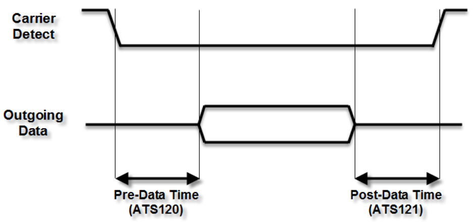
Company Confidential 43 Raveon Technologies Corp.
as indicated in the diagram below. The polarity of the carrier detect signal can be
inverted with the ATDCD command.
1. Data Framing
If Data Framing is enabled, any other Carrier Detect and flow control
output configuration is ignored. Set ATR1 3 to enable. Set ATS120 and
ATS121 to set the number of milliseconds for pre and post data time. This
feature is available in firmware version A31 and later.
Company Confidential 44 Raveon Technologies Corp.
Unused Page??

Company Confidential 45 Raveon Technologies Corp.
10. Troubleshooting
Symptom: Unit will not receive
Solution #1. Verify that the modem is on the correct RF channel. If it is, the RX LED should
blink every time another modem tries to transmit to it. If the RX LED does not blink when it
should be receiving, it is on the wrong RF frequency.
Soultion #2. If the addresses match, and RX LED blinks but still no reception of data, verify
that the RTS signal is asserted. The M8 will not output data if the RTS signal on the DB-9 I/O
connector is not asserted. If the user’s hardware cannot assert the RTS hardware line, disable
hardware flow control in the M8 modem, using the ATCH 0 command.
Solution #3. If the RX LED blinks, verify that the Unit Address of the sending modem matches
the unit address of the receiving modem. If this is OK, verify that the over-the-air baud rate of all
modems is the same (ATR2 command).
Solution #4. Verify Low Power Mode. The M8 has an optional Low Power Mode (LPM). If
LPM is enabled, the M8 will power down whenever the DTR line of the serial port is turned off.
The Power LED will blink once every 10 seconds in the LPM mode. The ATSM command is
used to set or read the Low Power Mode. ATSM 1 enables it, and ATSM 0 disables it. If LPM is
used (ATSM 1), then the M8 will turn off when the DTR line is off, or the program connected to
the serial port is closed, or the RS-232 connector is un plugged.
Symptom: Unit will not transmit
Solution #1. Verify that CTS is wired. Some devices that could be connected to the M8 will
require the CTS signal to be asserted. The M8 does assert this signal, but if the wire is not
connected, you device may not be outputting data to the M8. If the TX LED blinks, the M8 is
transmitting data. Every time data enters the modem, the TX LED should blink
Solution #2. Verify that serial port timeout is OK. The ATG0 command sets the number of
microseconds that the M8 will look for in the serial input data stream. If a pause greater than this
value happens, the modem will transmit. If the ATG0 paramter is set very large, say 2000000,
this means 2 seconds, and the modem may simply be waiting a long time
Solution #3. Verify that the radio channel is clear or BCL is off. The ATBC 1 command
enables Busy Channel Lockout. If BCL is on, the modem will not transmit on a busy channel.
The ATBC 0 command turns it off, and thus the modem will transmit when it needs to, regardless
if the channel is busy. The RX led on the front of the modem is illuminated whenever the radio
channel is busy (RF present).
Solution #4. Verify Low Power Mode. The M8 has an optional Low Power Mode (LPM). If
LPM is enabled, the M8 will power down whenever the DTR line of the serial port is turned off.
The Power LED will blink once every 10 seconds in the LPM mode. The ATSM command is
used to set or read the Low Power Mode. ATSM 1 enables it, and ATSM 0 disables it. If LPM is
used (ATSM 1), then the M8 will turn off when the DTR line is off, or the program connected to
the serial port is closed, or the RS-232 connector is un plugged.
Symptom: Receive light blinks, but no data is received
Solution #1. Verify Input/Output Configuration. The M8 has numerous I/O options. RS232 is
standard, but Ethernet, RS485 or RS422 may be configured also. Use the ATIO command to
view how the I/O is configured. ATIO 0 is the default (RS232 mode).
Solution #2. Verify the serial port baud rate. This is difficult if it is set wrong, because you
cannot enter the command mode to check it. Try all possible baud rates, and see if one of them
works with the modem. Alternately, remove the rear cover of the modem, and press the CONFIG

Company Confidential 46 Raveon Technologies Corp.
button. This will force the modem into the Command Mode, as well as set the serial port to 9600
baud, 8 data bits, one stop, and no parity. If the baud-rate was OK, verify the AT, BT and CT
times, that they are long enough for you to enter the +++ string.
Symptom: Long delay before transmitting
Solution #1. Verify that serial port timeout is OK. The ATR3 command sets the number of
milliseconds that the M8 will look for in the serial input data stream. If a pause greater than this
value happens, the modem will transmit. If the ATG0 parameter is set very large, say 2000, this
means 2 seconds, and the modem may simply be waiting a long time. Typical settings for this
parameter are 20 (20mS).
Symptom: Cannot enter Command Mode
Solution #1. Verify the serial port baud rate. This is difficult if it is set wrong, because you
cannot enter the command mode to check it. Try all possible baud rates, and see if one of them
works with the modem. Alternately, remove the rear cover of the modem, and press the CONFIG
button. This will force the modem into the Command Mode, as well as set the serial port to 9600
baud, 8 data bits, one stop, and no parity. If the baud-rate was OK, verify the AT, BT and CT
times, that they are long enough for you to enter the +++ string.
Solution #2. Handshaking. You may have hardware handshaking enabled on your terminal
program, but the hardware or cable may not support it. Disable hardware handshaking on your
terminal program to verify this is the issue.
Symptom: Modem appears dead.
Solution #1. Verify the power is on. When the modem has good DC power, the PWR LED
will blink once per second. If it is not blinking, either the modem does not have power, the
modem is broken, or the LEDs have been disabled via the ATL0 command.
Solution #2. Verify the internal fuse OK. There is an internal fuse in the RV-M8, protecting it
from reverse-voltage and electrical failures. If the power LED does not blink or come on when
DC is applied, check the fuse and replace it with the same type 3-amp mini fuse, and try again. If
you replace the fuse, the unit must be carefully check for damage and proper operation before
being installed. If you replace the fuse, you must use a Littlefuse brand fuse, part number
0297003 or Raveon part, number 1X726-3 to maintain calibration of your unit.
Solution #3. Verify Low Power Mode. The M8 has an optional Low Power Mode (LPM). If
LPM is enabled, the M8 will power down whenever the DTR line of the serial port is turned off.
The Power LED will blink once every 10 seconds in the LPM mode. The ATSM command is
used to set or read the Low Power Mode. ATSM 1 enables it, and ATSM 0 disables it. If LPM is
used (ATSM 1), then the M8 will turn off when the DTR line is off, or the program connected to
the serial port is closed, or the RS-232 connector is un-plugged.
Symptom: Repeater will not repeat.
Solution #1. Verify the repeater’s Unit ID is unique. An RV-M8 configured to be a repeater
will not repeat messages it originated. If other units in the system have the same ID as the
repeater, the repeater will not repeat them because it thinks that it originated the transmission.
Set the MTID of the repeater to a unique ID number.
11. Antenna information
Key to a successful installation is the choice and installation of a good antenna
system. A good quality antenna can more than double the range of a radio
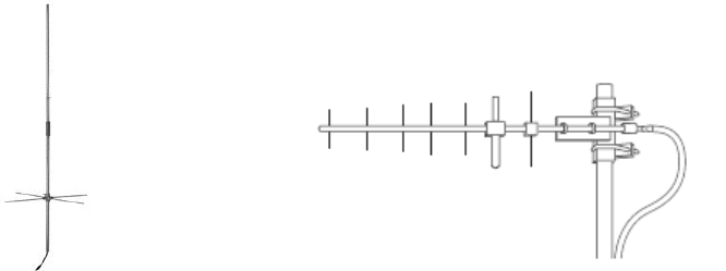
Company Confidential 47 Raveon Technologies Corp.
system. Properly locating the antenna is vital to creating a quality radio link, and
a poor installation can decrease the range of the system by as much at 90%.
Use these guidelines to evaluate your antenna system design, and be sure
contact a quality radio communication equipment distributor such as Talley
Electronics (http://www.talleycom.com ) to help choose the proper antenna for
your system.
To increase your communications range, locate the antenna high as needed,
practical, safe, and allowed by your license. On fixed base-station applications,
you may utilize an antenna with gain. Note: The maximum Permissible Exposure
(MPE) for this product was computed using a 0dB gain antenna, and must be
recalculated if a gain antenna is used.
Height Try to locate the antenna as high above obstructions, vehicle, and buildings as
possible. UHF radio channels require a clear “line-of-sight” between the
transmitter and the receiver. Radio waves will penetrate buildings, and reflect off
and around obstacles, but the fewer obstacles between stations the better the
signal quality.
Gain Antennas are specified by their gain. They actually do not have gain, but rather
they can increase the strength of a signal in certain directions, at the expense of
attenuating signals from other directions. Gain antennas always have “patterns”
of gain. It is important you understand the pattern of your antenna. Omni
directional antennas will receive from almost any angle, 360 degrees around
them.
Omni Antenna Directional Antenna
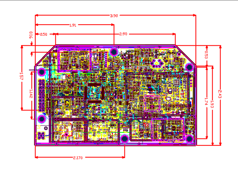
Company Confidential 48 Raveon Technologies Corp.
12. Mechanical
Company Confidential 49 Raveon Technologies Corp.
Limited Two Year Warranty
If within 24 months from date of purchase, this Product fails conforms to Raveon Technologies
Corporation’s (the Company) published specifications for the model purchased due to a defect in
material or workmanship, Raveon Technologies Corporation will repair or replace it, at Raveon’s
sole discretion. This warranty is extended to the original purchasing end user only and is not
transferable. Any claim for breach of warranty must be brought to the Company’s attention within
such twelve (24) month period and the Product must be returned for action on any such claim
within twelve (24) months from the date of purchase Within a reasonable period of time after a
claim, the Company will correct any failure of the Product to conform to specifications or any
defect in materials or workmanship, or replace the Product, or at its option provide a full refund of
the purchase price. A repaired or replaced Product is warranted for 90 days from the date of
return shipment to the buyer, or for the balance of the original warranty period, whichever is
longer. These remedies are the buyer’s exclusive remedies for breach of warranty.
This warranty does not apply to: (a) product damage caused by accident, dropping or abuse in
handling, acts of God or any negligent use; (b) units which have been subject to unauthorized
repair, opened, taken apart or otherwise modified; (c) units not used in accordance with
instructions; (d) damages exceeding the cost of the product; (e) batteries; (f) the finish on any
portion of the product, such as surface and/or weathering, as this is considered normal wear and
tear; (g) transit damage, initial installation costs, removal costs, or reinstallation costs; (h) damage
due to lighting, floods, fire, or earthquakes (i) any product, components or parts not manufactured
by the Company (j) defects caused by failure to provide a suitable installation environment for the
Radio; (k) damage during shipment; (l) that the Product will be free from any claim for
infringement of any patent, trademark, copyright or other proprietary right, including trade secrets.
RAVEON TECHNOLOGIES INCORPORATED WILL NOT BE LIABLE FOR INCIDENTAL OR
CONSEQUENTIAL DAMAGES ARISING DIRECTLY OR INDIRECTLY OUT OF THE
OWNERSHIP, USE OR OPERATION OF THE RADIO REGARDLESS OF WHETHER SUCH
DAMAGES ARE PREDICATED OR BASED UPON BREACH OF WARRANTY, BREACH OF
CONTRACT, NEGLIGENCE, STRICT TORT, OR ANY OTHER LEGAL THEORY. SUCH
DAMAGES INCLUDE, BUT ARE NOT LIMITED TO, LOSS OF PROFITS, LOSS OF SAVINGS
OR REVENUE, LOSS OF USE OF THE RADIO OR ANY ASSOCIATED EQUIPMENT, COST
OF CAPITAL, COST OF ANY SUBSTITUTE EQUIPMENT, FACILITIES OR SERVICES, THE
CLAIMS OF THIRD PARTIES, INCLUDING CUSTOMERS AND INJURY TO PROPERTY.
SOME STATES DO NOT ALLOW THE EXCLUSION OR LIMITATION OF INCIDENTAL OR
CONSEQUENTIAL DAMAGES, SO THE ABOVE LIMITATION OR EXCLUSION MAY NOT
APPLY TO YOU. THIS WARRANTY IS IN LIEU OF ALL OTHER EXPRESS OR IMPLIED
WARRANTIES. ALL IMPLIED WARRANTIES, INCLUDING THE WARRANTY OF
MERCHANTABILITY AND THE WARRANTY OF FITNESS FOR A PARTICULAR PURPOSE,
ARE HEREBY MODIFIED TO EXIST ONLY AS CONTAINED IN THIS LIMITED WARRANTY,
AND SHALL BE OF THE SAME DURATION AS THE WARRANTY PERIOD STATED ABOVE.
SOME STATES DO NOT ALLOW LIMITATIONS ON THE DURATION OF AN IMPLIED
WARRANTY, SO THE ABOVE LIMITATION MAY NOT APPLY TO YOU.
This warranty gives you specific legal rights and you may also have other rights which vary from
state to state.
No employee of the Company, or any other party is authorized to make any warranty in addition
to those made in this document. This warranty limits the Company’s risk and allocates the risks
of product failure between the Company and the buyer. This allocation is recognized by both
parties and is reflected in the price of the goods. The buyer acknowledges that it has read this
warranty, understands it, and is bound by its terms. This limited warranty is governed by the laws
of the State of California, without reference to its conflict of law provisions or the U.N. Convention
on Contracts for the International Sale of Goods.
Company Confidential 50 Raveon Technologies Corp.
Warranty service is available by mailing postage prepaid to:
Raveon Technologies Corporation
2320 Cousteau Court
Vista, CA 92081 - USA
To obtain warranty service, include a copy of the original sales receipt or invoice showing the
date, location, and price of purchase. Include a written description of the problem with the
product, a phone number and name of person who may be contacted regarding the problem, and
the address to where the product should be returned.
Products repaired under warranty will typically have their program memories erased and reset to
factory default settings.