Raveon Technologies orporated RV-M5-UC RF Data Modem User Manual revised manual
Raveon Technologies, Incorporated RF Data Modem revised manual
UserManual.wiki
>
Raveon Technologies orporated
>
RV M5 UC User Manual
revised manual
Navigation menu
Upload a User Manual
Namespaces
Wiki Guide
HTML
PDF
Info
Views
User Manual
Discussion / Help
Navigation
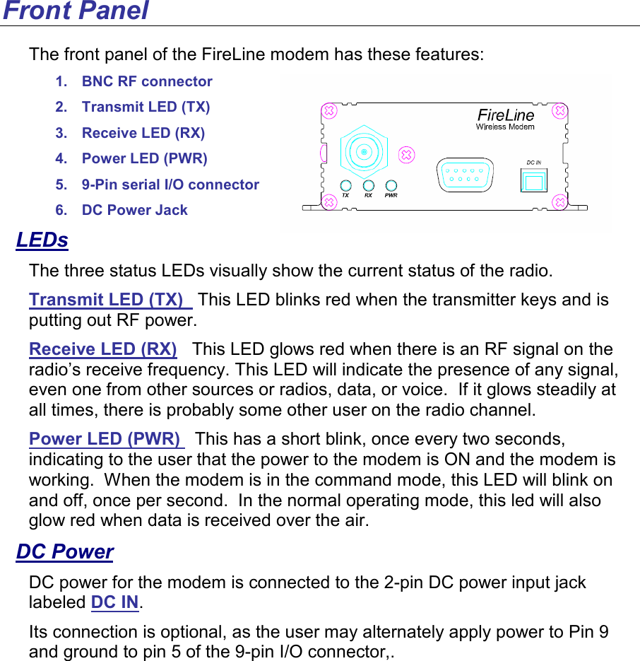
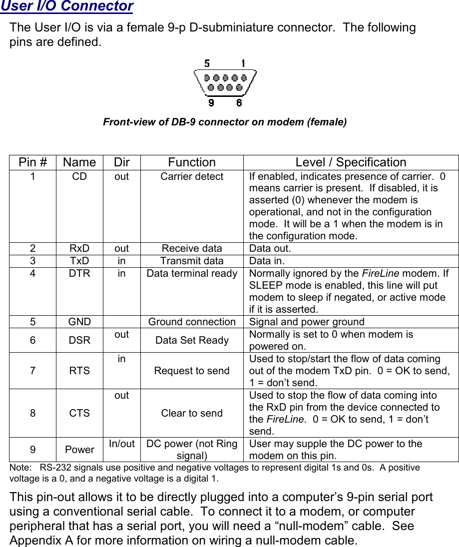
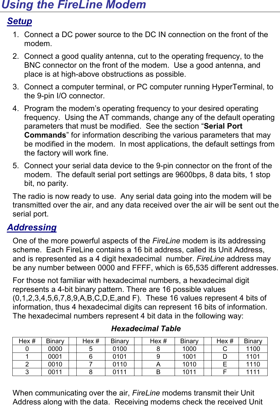
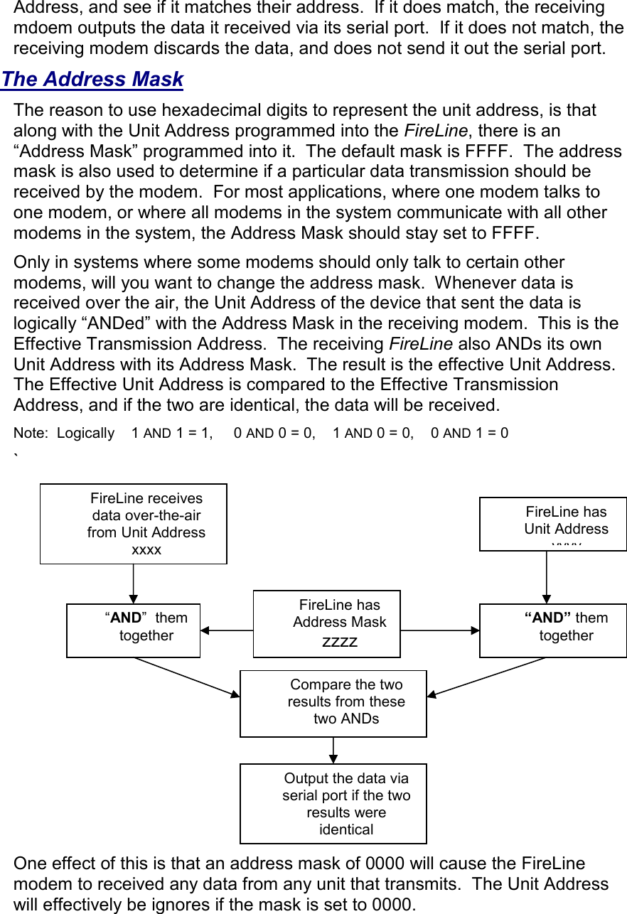
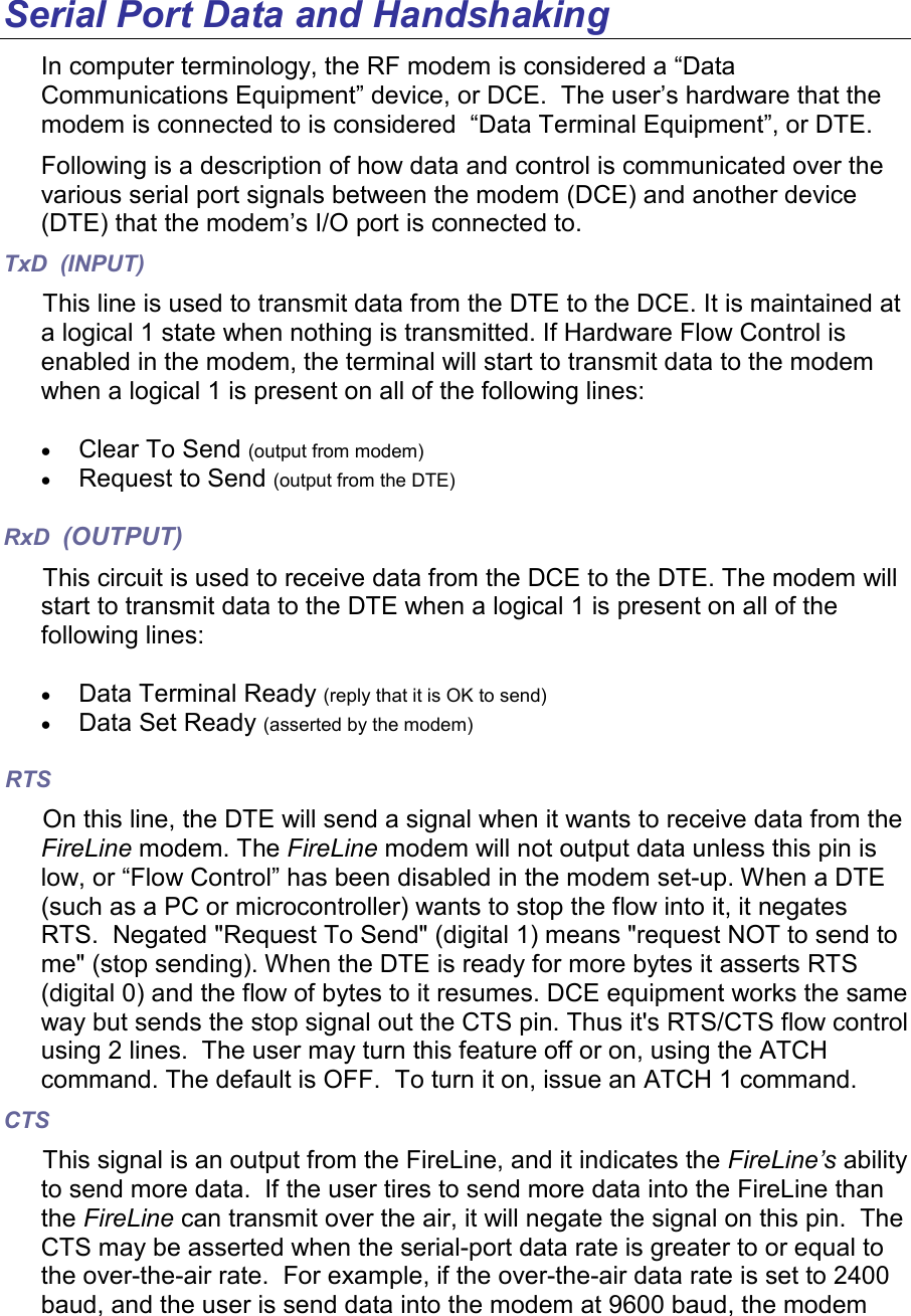
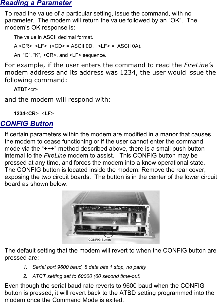
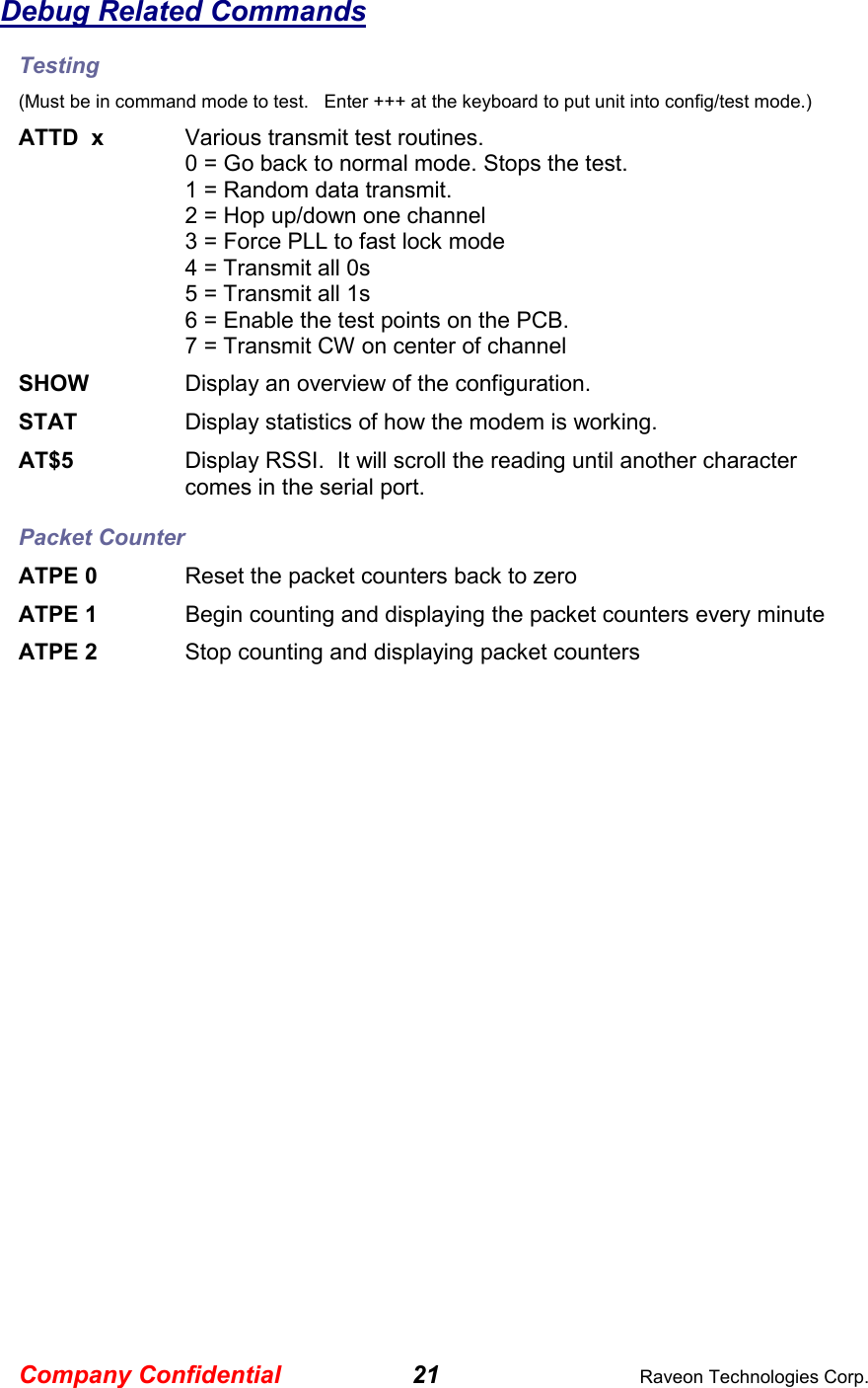
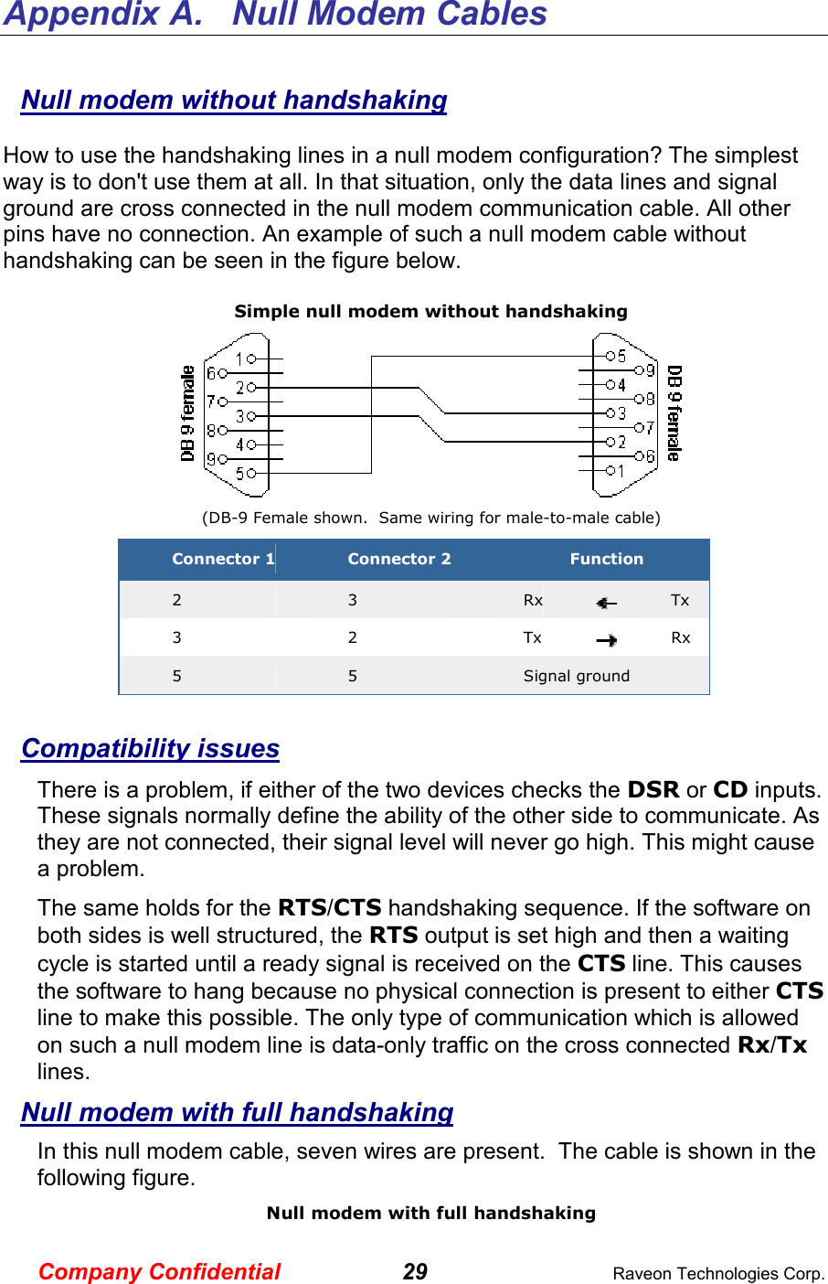
![User Serial Port Commands Overview The asynchronous serial portion the RF modem is used to send and receive data over the air, as well as to configure the RF modem. In normal operation, the user sends data into the TxD pin of the user port, and this data is transmitted over the air. Received data from another RF modem is output to the user via the RxD pin of the user port. This is the default operating condition of the RF modem. There also is a “Command Mode”. In the Command Mode, the FireLine modem accepts commands via the TxD pin. The commands can be used to change certain internal parameters of the FireLine modem. Command Mode The FireLine modem may be put into a “Command Mode”, by entering a sequence of three plus characters (+++). To keep the FireLine modem from accidentally entering the Command Mode because of the +++ pattern occurring in a stream of data entering the modem, there must be a pause in the data stream before the +++ as well as after the +++ is sent. If either pause is missing, the modem will not enter the command mode. Using serial communications software such as HypterTerminal, send the 3-character command sequence “+++” while observing times of silence before [BT (Silence Before Sequence) Command] and after [AT (Silence After Sequence) Command] the command characters. The default sequence for entering into AT Command Mode: The default sequence for entering into AT Command Mode: The default sequence for entering into AT Command Mode: The default sequence for entering into AT Command Mode: 1. No characters sent for 1 second. 2. Input three (3) plus characters (“+++”) within one (1) second. 3. No characters sent for one (1) second. When the FireLine modem first enters the Command Mode, it sends the phrase “FireLine” out it serial port, and then an “OK” sequence. The “OK” sequence is a sequence of 4 characters: An “O”, “K”, <CR>, and <LF> characters (<CR> = ASCII 0D, <LF> = ASCII 0A) Setting a Parameter To set a parameter in the FireLine modem, enter the configuration mode as described above. Then enter the proper AT command, a space, the parameter, and then a carriage return. For Example, to set the address of the FireLine modem to 1234, enter the following command: ATDT 1234 <CR>.](https://usermanual.wiki/Raveon-Technologies-orporated/RV-M5-UC/User-Guide-622481-Page-16.png)