Rayence RY1012WA Medical Image Processing Unit User Manual
Rayence Co., Ltd. Medical Image Processing Unit
UserManual.wiki
>
Rayence
>
RY1012WA User Manual
>
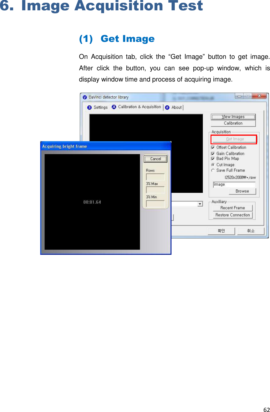
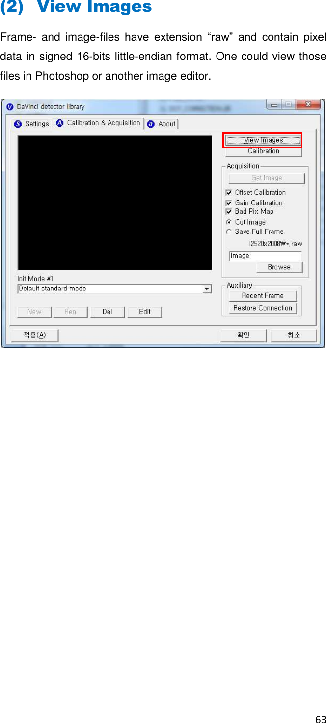
User Manual
Contents
1.
User Manual
2.
Users Manual
User Manual
Navigation menu
Upload a User Manual
Namespaces
Wiki Guide
HTML
PDF
Info
Views
User Manual
Discussion / Help
Navigation

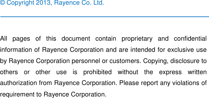


![39 (5) IP set up [My Network Places] → [Properties] → [Local Area Connection] → [Properties] → [Internet Protocol (TCP/IP)] → [Use the following IP address] IP address: Obtain an IP address automatically IP address : Obtain an IP address automatically](https://usermanual.wiki/Rayence/RY1012WA.User-Manual/User-Guide-2812328-Page-44.png)
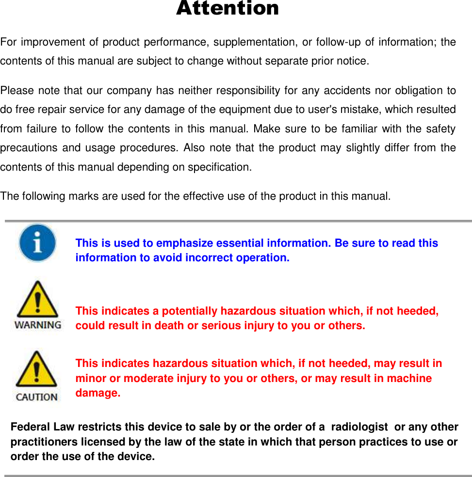
![53 2nd Step Push “Get Bright” button at different four of X-ray condition. The X-ray condition should be set or tested before, same as the level of ‘1.2’. Push “Get Bright” button at least 2 times at same condition, and then the offset subtracted bright (gain) is generated which of filename is “xNNNNNA.raw(Refer to NOTE) Figure 2: Get bright. Click button [Get Bright]. It will produce frame with name %CAL% xNNNNNA.raw, where NNNNN is median pixel’s value within current image borders after offset calibration (cut frame edges are never used during calibration). Suffix ‘A’ (it also could be ‘B’,’C’ etc) avoids casual coincidence of file names.](https://usermanual.wiki/Rayence/RY1012WA.User-Manual/User-Guide-2812328-Page-58.png)

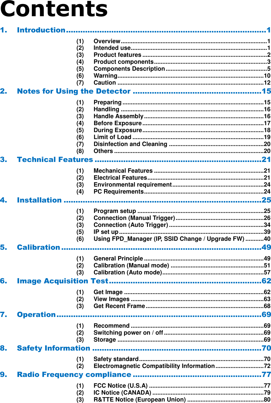
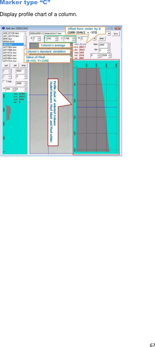
![65 Histogram’s presentation Relative Histogram Scale [H]=1000 means that that the distance depicted as “H” on the drawing matches 1% of total number of pixels. Respectively [H]=100 means that “H” matches 0.1% of pixels and [H]=500 means that “H” matches 0.5% of pixels.](https://usermanual.wiki/Rayence/RY1012WA.User-Manual/User-Guide-2812328-Page-70.png)
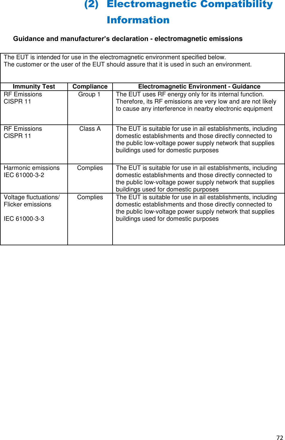
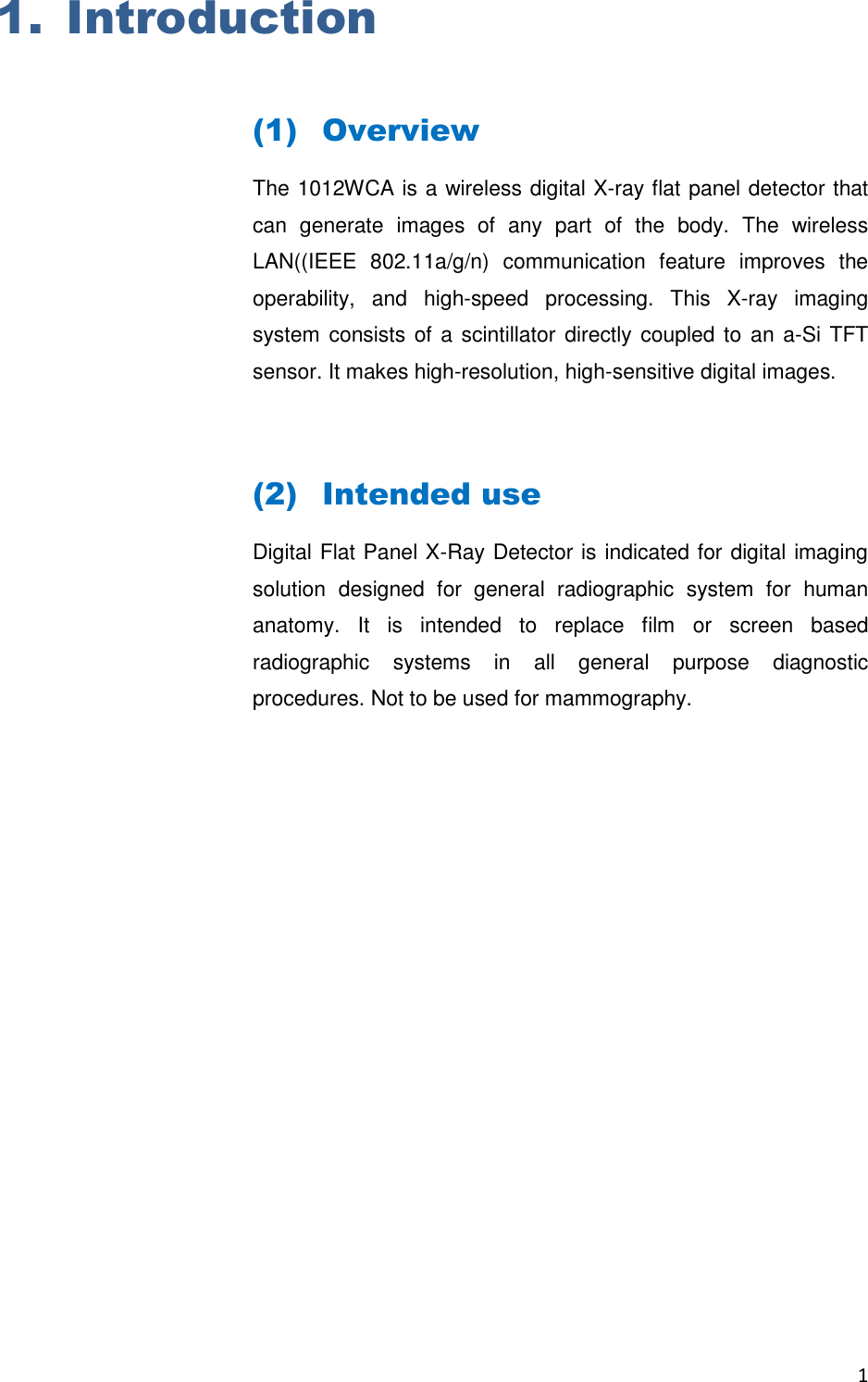
![74 Guidance and manufacturer’s declaration - electromagnetic immunity The EUT is intended for use in the electromagnetic environment specified below. The customer or the user of the EUT should assure that it is used in such an environment. Immunity test IEC 60601-1-2 test level Compliance level Electromagnetic environment - guidance Conducted RF IEC 61000-4-6 Radiated RF IEC 61000-4-3 3 Vrms 150 kHz to 80MHz 3 V/m 80 MHz to 2.5GHz V1=3Vrms E1=3V/m Portable and mobile RF communications equipment should be used no closer to any part of the EUT, including cables, than the recommended separation distance calculated from the equation applicable to the frequency of the transmitter. Recommended separation distance : PVd15.3 PEd15.3 80MHz to 800MHz PEd17 800MHz to 2.5GHz where P is the maximum output power rating of the transmitter in watts (W) according to the transmitter manufacturer and d is the recommended separation distance in meters (m). Field strengths from fixed RF transmitters, as deter-mined by an electromagnetic site survey, a should be less than the compliance level in each frequency range. b Interference may occur in the vicinity of equipment marked with the following symbol : NOTE 1) At 80MHz and 800MHz, the higher frequency range applies. NOTE 2) These guidelines may not apply in all situations. Electromagnetic propagation is affected by absorption and reflection from structures, objects and people. a Field strengths from fixed transmitters, such as base stations for radio (cellular/cordless) telephones and land mobile radios, amateur radio, AM and FM radio broadcast and TV broadcast cannot be predicted theoretically with accuracy. To assess the electromagnetic environment due to fixed RF transmitters, an electromagnetic site survey should be considered. If the measured field strength in the location in which the EUT is used exceeds the applicable RF compliance level above, the EUT should be observed to verify normal operation. If abnormal performance is observed, additional measures may be necessary, such as re-orienting or relocating the EUT. b Over the frequency range 150kHz to 80MHz, field strengths should be less than [V1] V/m.](https://usermanual.wiki/Rayence/RY1012WA.User-Manual/User-Guide-2812328-Page-79.png)
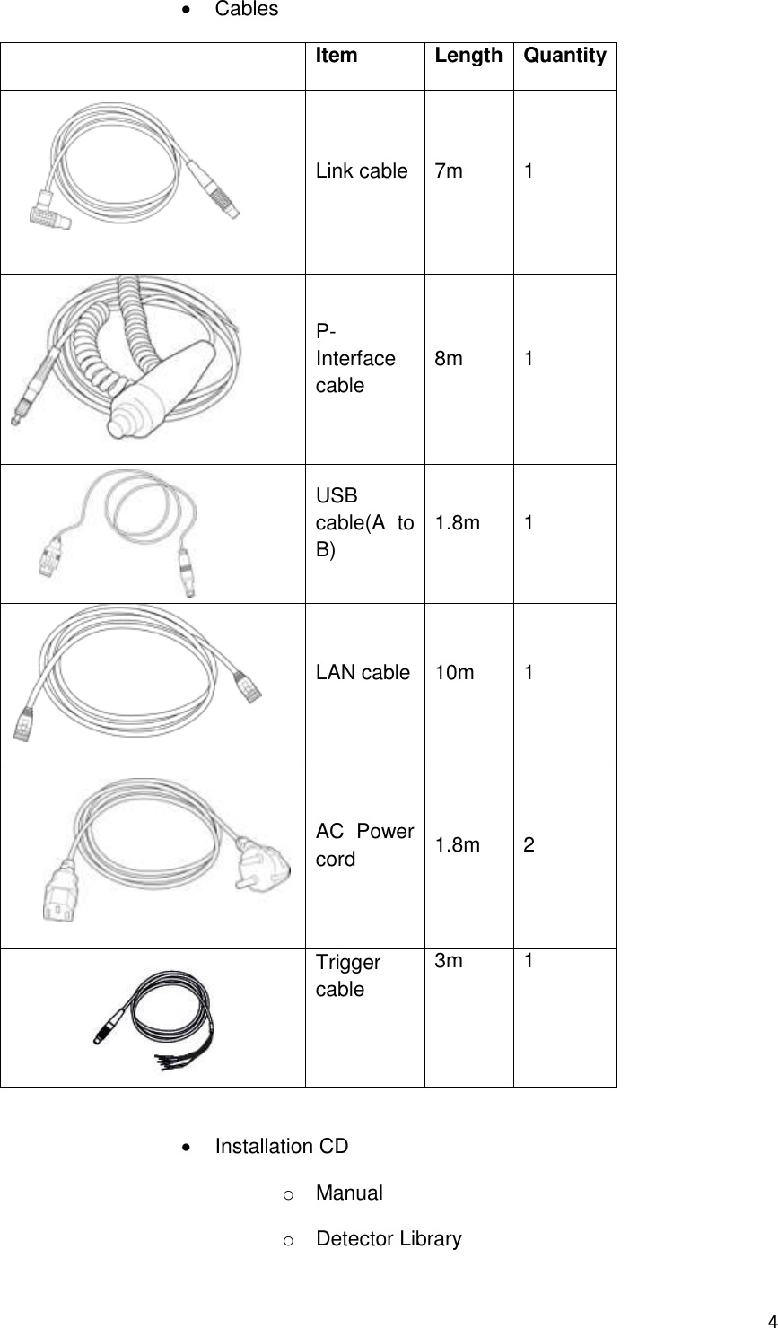
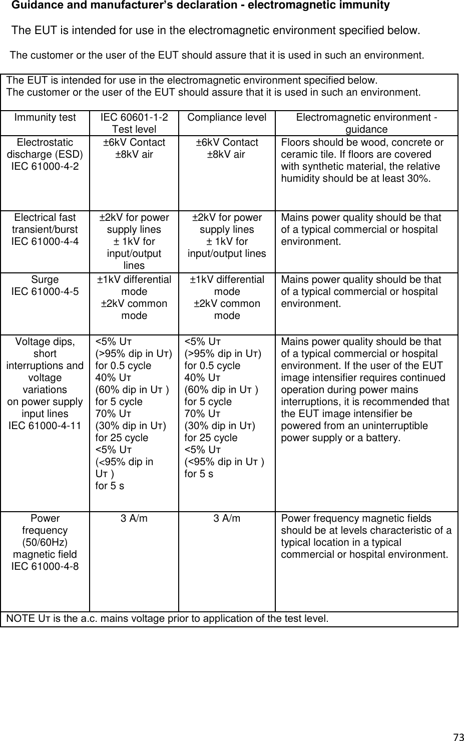
![75 Recommended separation distances between portable and mobile RF communications equipment and the EUT There is intended for use in an electromagnetic environment in which radiated RF disturbances are controlled. The customer or the user of the EUT can help Prevent electromagnetic interference by maintaining a minimum distance between portable and mobile RF communications equipment (transmitters) and the EUT as recommended below, according to the maximum output power of the communications equipment. Separation distance according to frequency of transmitter [m] IEC 60601-1-2 Frequency of Transmitter Equation Rated maximum output power of transmitter [W] 150kHz to 80MHz PVd15.3 V1=3Vrms Separation Distance (meters) 80MHz to 800MHz PEd15.3 E1=3V/m Separation Distance (meters) 800MHz to 2.5GHz PEd17 E1=3V/m Separation Distance (meters) 0.01 0.116 0.1166 0.2333 0.1 0.368 0.3687 0.7378 1 1.166 1.1660 2.3333 10 3.687 3.6872 7.3785 100 11.660 11.6600 23.333 For transmitters rated at a maximum output power not listed above, the recommended separation distance d in meters (m) can be estimated using the equation applicable to the frequency of the transmitter, where p is the maximum output power rating of the transmitter in watts (W) according to the transmitter manufacturer. NOTE 1) At 80MHz and 800MHz, the separation distance for the higher frequency range applies. NOTE 2) These guidelines may not apply in all situations. Electromagnetic propagation is affected by absorption and reflection from structures, objects and people. a Field strengths from fixed transmitters, such as base stations for radio (cellular/cordless) telephones and land mobile radios, amateur radio, AM and FM radio broadcast and TV broadcast cannot be predicted theoretically with accuracy. To assess the electromagnetic environment due to fixed RF transmitters, an electromagnetic site survey should be considered. If the measured field strength in the location in which the EUT is used exceeds the applicable RF compliance level above, the EUT should be observed to verify normal operation. If abnormal performance is observed, additional measures may be necessary, such as re-orienting or relocating the EUT. b Over the frequency range 150kHz to 80MHz, field strengths should be less than [V1] V/m. Name Shield Type Length Notes Link cable Shielded 6 m Provided with wiring unit. P-interface cable Non-shielded 8 m Provided with X-ray interface unit. USB cable (A to B) Non-shielded 1.8 m Provided with AGI unit. AC power cord (220V) Shielded 1.8 m Provided with charger unit.](https://usermanual.wiki/Rayence/RY1012WA.User-Manual/User-Guide-2812328-Page-80.png)
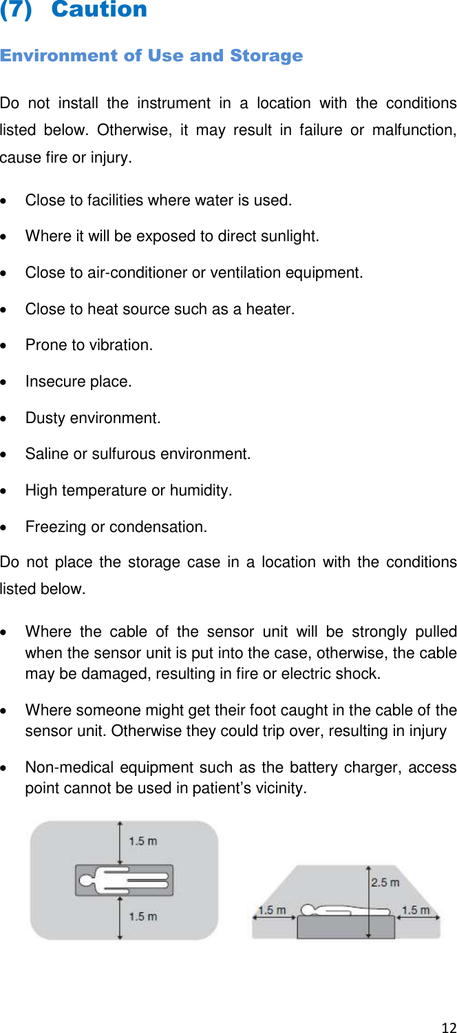
![86 Appendix Dimension [unit : mm]](https://usermanual.wiki/Rayence/RY1012WA.User-Manual/User-Guide-2812328-Page-91.png)