Rayence RY1012WGB Industrial Image Processing Unit User Manual
Rayence Co., Ltd. Industrial Image Processing Unit
Rayence >
User Manual
1012WGB User manual

© Copyright 2014, Rayence Co. Ltd.
All pages of this document contain proprietary and confidential
information of Rayence Corporation and are intended for exclusive use
by Rayence Corporation personnel or customers. Copying, disclosure to
others or other use is prohibited without the express written
authorization from Rayence Corporation. Please report any violations of
requirement to Rayence Corporation.
Attention
For improvement of product performance, supplementation, or follow-up of information; the
contents of this manual are subject to change without separate prior notice.
Please note that our company has neither responsibility for any accidents nor obligation to
do free repair service for any damage of the equipment due to user's mistake, which resulted
from failure to follow the contents in this manual. Make sure to be familiar with the safety
precautions and usage procedures. Also note that the product may slightly differ from the
contents of this manual depending on specification.
The following marks are used for the effective use of the product in this manual.
Attention, consult accompanying documents.
This is used to emphasize essential information. Be sure to read this
information to avoid incorrect operation.
This indicates hazardous situation which, if not heeded, may result in
minor or moderate injury to you or others, or may result in machine
damage.
This indicates a potentially hazardous situation which, if not heeded, could
result in death or serious injury to you or others.
Federal Law restricts this device to sale by or the order of a radiologist or
any other practitioners licensed by the law of the state in which that
person practices to use or order the use of the device.
Contents
1. Introduction...................................................................................... 1
(1) Overview .......................................................................................... 1
(2) Product features .............................................................................. 1
(3) Product component ........................................................................ 2
(4) Components Description ............................................................... 4
(5) Warning ............................................................................................ 9
(6) Caution ........................................................................................... 11
2. Notes for Using the Detector ........................................................ 13
(1) Handling ......................................................................................... 13
(2) Handle Assembly .......................................................................... 13
(3) Before Exposure............................................................................ 14
(4) During Exposure ........................................................................... 14
(5) Disinfection and Cleaning ............................................................ 14
(6) Others ............................................................................................. 14
3. Technical Features ........................................................................ 15
(1) Mechanical Features ..................................................................... 15
(2) Electrical Features ........................................................................ 15
(3) Environmental requirement ......................................................... 18
(4) PC Requirements .......................................................................... 19
4. Installation ..................................................................................... 20
(1) Program setup ............................................................................... 20
(2) Connection (Manual Trigger) ....................................................... 21
(3) Connection (Auto Trigger) ............................................................ 29
(4) IP set up ......................................................................................... 34
(5) Checking Connection ................................................................... 35
5. Calibration ...................................................................................... 36
(1) General Principle ........................................................................... 36
(2) Calibration ...................................................................................... 38
6. Image Acquisition Test.................................................................. 43
(1) Get Image ....................................................................................... 43
(2) View Images ................................................................................... 44
7. Operation ........................................................................................ 49
(1) Recommend ................................................................................... 49
(2) Switching power on / off ............................................................... 49
(3) Storage ........................................................................................... 49
8. Radio Frequency compliance ........................................................ 50
(1) FCC Notice (U.S.A) ........................................................................ 50
(2) IC Notice (CANADA) ...................................................................... 52
(3) R&TTE Notice (European Union) ................................................. 53
9. Maintenance .................................................................................. 54
(1) Maintenance ................................................................................... 54
(2) Cleaning ......................................................................................... 54
(3) Inspection ...................................................................................... 55
(4) Marking and labeling symbols ..................................................... 56
Appendix .............................................................................................. 58
1
1. Introduction
(1) Overview
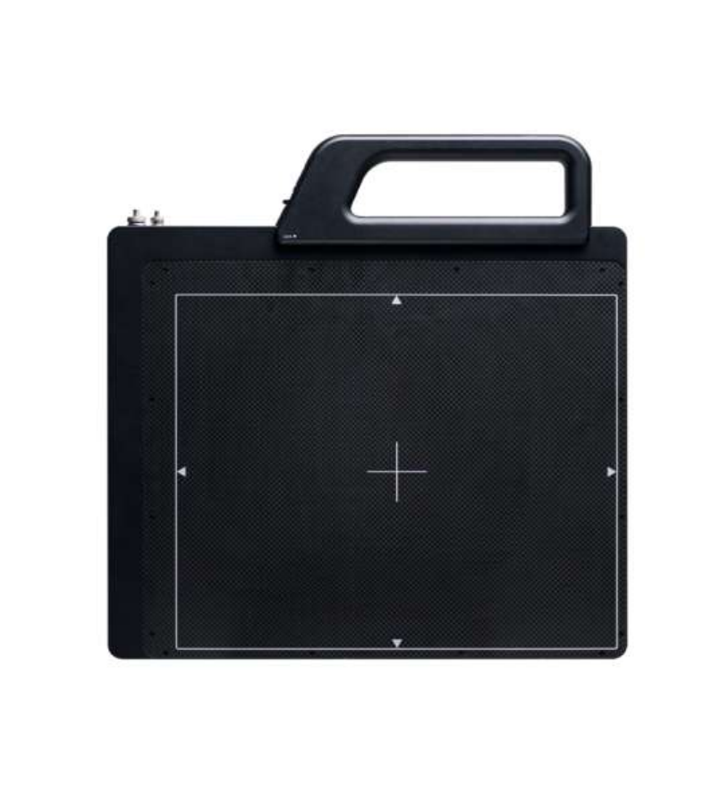
The 1012WGB is a digital X-ray flat panel detector that can
generate images of NDT. This X-ray imaging system consists of
a scintillator directly coupled to an a-Si TFT sensor. It makes
high-resolution, high-sensitive digital images.
(2) Product features
Based on a-Si TFT active matrix
Compact (18mm thickness) and light weight
High resolution : Min. 2.5 lp/mm, Max 3.9 lp/mm
14/16-bit digital output
Easy integration
2
(3) Product component
Industrial Image Processing Unit
Photo
Item
Quantity
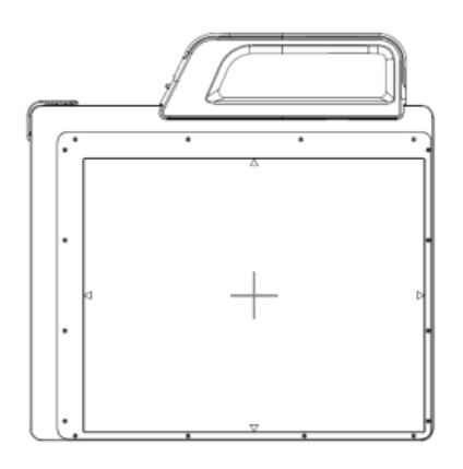
Detector
1
Handle
1
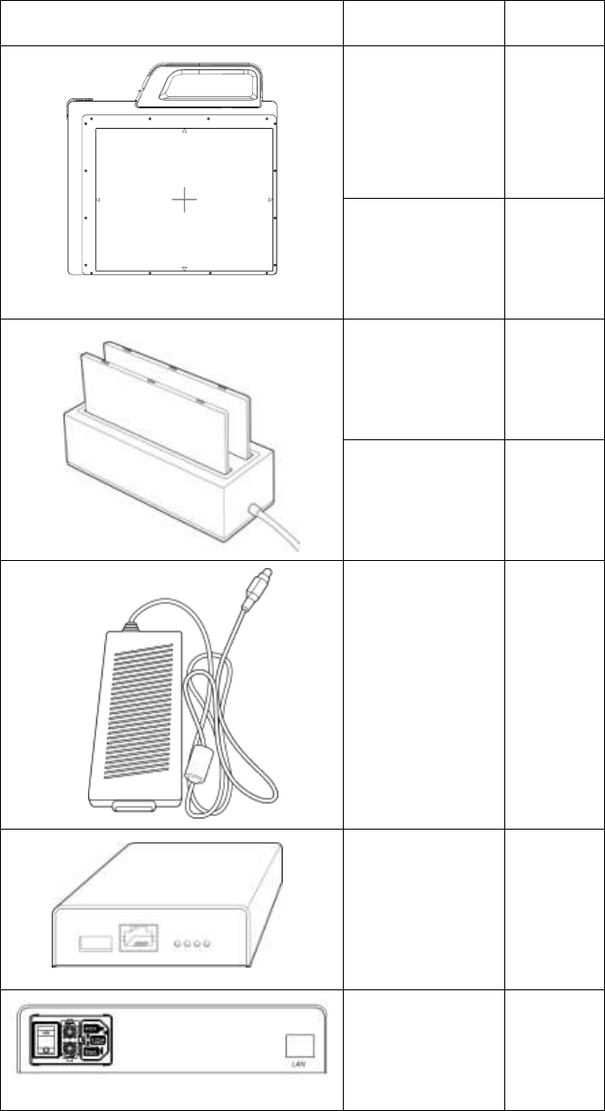
Battery pack
2
Battery charger
1
Charger
adapter
1
AGI
1
Power supply
box
1
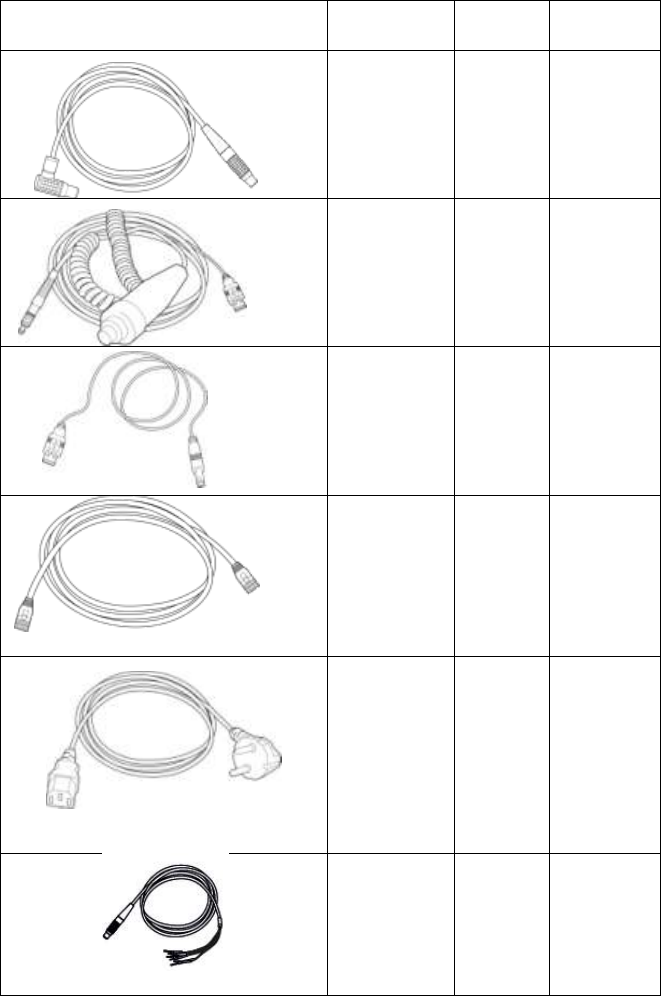
3
Cable
Item
Length
Quantity
Link cable
6m
1
P-
Interface
cable
8m
1
USB
cable(A to
B)
1.8m
1
LAN cable
10m
1
AC Power
cord
1.8m
1
Trigger
cable
3m
1
Installation CD
o Manual
o Detector Library
Option
o Trigger cable
4
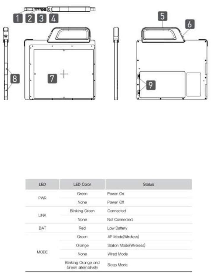
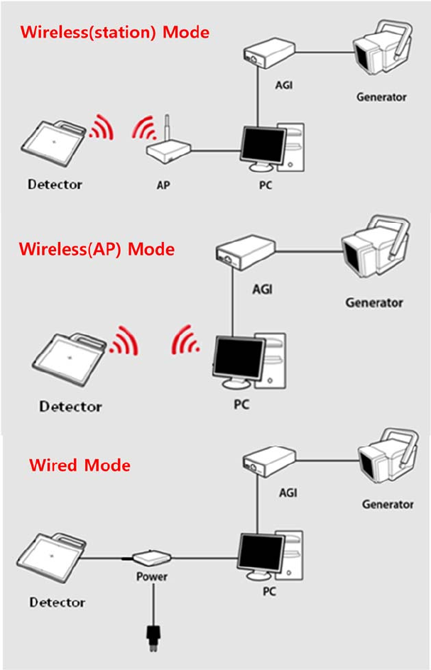
(4) Components Description
The detector is designed to capture radiographic images.
Captured images are transmitted to PC using the wired
connection.
(1) Detector
1. Link Cable Connector : This is a connector for Wire
communication and power supplying. Connect the detector to the
power supply using Link cable.
2. LED indicator: The LED indicates the state of detector.
3. Power Button : Power on / off switch (Press for over 3 seconds)
4. AP Mode Select Button : Button for changing mode
5. Handle : Hold this handle when carrying the sensor unit. It is
removable. (Horizon/Vertical)
5
6. Handle unlock-lever : This is an unlock-lever to remove handle.
7. CFRP(Carbon Fiber Reinforced Plastic) : The part of the patient’s
body to which an image is to be taken should be placed against this
plate.
8. Shock sensor : Detector has built-in 2 Shock sensors. It detects
and records impact and mishandling of fragile
9. Battery unlock-lever : This is an unlock-lever to remove battery.
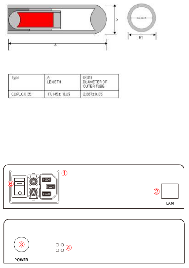
(2) Power supply
1. Power plug connector: Connect with AC power supply cord
2. LAN connector : Ethernet port for transmitting the image/command
between detector and PC
3. Link cable connector: Power connector for detector operating
4. LED indicator: Four LEDs to display the status
※ Changeable part: Fuse T3.15 AL 250V
6
(3) AGI
<AGI is needed on only Manual Trigger Mode>
1. Trigger connector: This is a connector for synchronization
between detector and generator. Connect the AGI to the generator
using P-interface cable..
2. USB connector: This is a connector for communication between
AGI and PC. Connect the AGI to the PC using USB cable
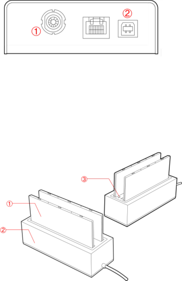
(4) Battery & Charger
1. Battery : Lithium ion battery. The number of times being acquired
image is 960 images(@ cycle time : 15s). The batteries last 2.5
hours and are rechargeable.
2. Charger : Two port cradle type.
3. LED indicator :
i. Orange on : charging
ii. Green on : Charging is completed.

7
※Wireless Module and Wireless Antenna
Wireless antennas:
The module adopts the latest 802.11n Dual-Band technology.
DUT does not support simultaneous transmission.
The transmitter of the module is powered by host equipment (Detector).
The antennas are 2 printed-dipole and correlated antennas.
Does not support beamforming.
※Wireless module:
The end product will use the in original certified transmitter module and will keep the original
authorization condition except the change in antenna of the module during the final end
product assembly.
Data transmission is always initiated by software, which is the passed down through the
MAC, through the digital and analog baseband, and finally to the RF chip. Several special
packets are initiated by the MAC. These are the only ways the digital baseband portion will
turn on the RF transmitter, which it then turns off at the end of the packet. Therefore, the
transmitter will be on only while one of the aforementioned packets is being transmitted. In
other words, this device automatically discontinues transmission in case of either absence of
information to transmit or operational failure.
This device complies with part 15 of the FCC Rules. Operation is subject to the following two
conditions: (1) This device may not cause harmful interference, and (2) this device must
accept any interference received, including interference that may cause undesired operation.
FCC CAUTION
Changes or modifications not expressly approved by the party responsible for compliance
could void the user’s authority to operate the equipment. This transmitter must not be co-
located or operated in conjunction with any other antenna or transmitter.
When installing it in a mobile equipment
This equipment complies with FCC radiation exposure limits set forth for an uncontrolled
environment and meets the FCC radio frequency (RF) Exposure Guidelines in Supplement
C to OET65. This equipment has very low levels of RF energy that it deemed to comply
without maximum permissive exposure evaluation (MPE). But it is desirable that it should be
installed and operated keeping the radiator at least 20cm or more away from person’s body
(excluding extremities: hands, wrists, feet and ankles).
When you use the detector with wire mode, the wireless function is automatically off.
※5150~5250 MHz band is restricted to indoor operations only.
8
This device complies with Industry Canada licence-exempt RSS standard(s). Operation is
subject to the following two conditions: (1) this device may not cause interference, and (2)
this device must accept any interference, including interference that may cause undesired
operation of the device.
Le present appareil est conforme aux CNR d'Industrie Canada applicables aux appareils
radio exempts de licence. L'exploitation est autorisee aux deux conditions suivantes : (1)
l'appareil ne doit pas produire de brouillage, et (2) l'utilisateur de l'appareil doit accepter tout
brouillage radioelectrique subi, meme si le brouillage est susceptible d'en compromettre le
fonctionnement.
Operations to just the specific band(s) : limited device Software program.
User cannot enable the other bands, because PC set up should be necessary.
(details for user manual_Ch.3 Installation and Calibration)

9
(5) Warning
Environment of Use and Storage
Follow the specified process of operational instructions written in
this manual for the safety of the users
Does not use or store the instrument near any flammable
chemicals such as thinner, benzene, etc. Also, this instrument is
not a category AP or APG equipment. If chemicals are spilled or
evaporate, it may result in fire or electric shock through contact
with electric parts inside the instruments. Also, some
disinfectants are flammable. Be sure to take care when using
them.
Connection
Do not connect the instrument with anything other than specified.
Otherwise, it may result in fire or electric shock.
To avoid the risk of electric shock, this equipment must only be
connected to a supply mains with protective earth.
Handling
Always be sure to keep checking the condition of the system to
ensure they are normal during the use of the instrument. If any
problem is found, take appropriate measures, such as stopping
the operation of the instrument, as required.
Never disassemble or modify the product as it may result in fire
or electric shock. Also, since the instrument incorporates parts
that may cause electric shocks and other hazardous parts,
touching them may cause death or serious injury.
Do not hit or drop the instrument. The instrument may be
damaged if it receives a strong jolt, which may result in fire or
electric shock if the instrument is used without it being repaired.
Make sure
to observe
the following right

10
When Problem Occurs
Should any of the following occur, immediately turn OFF the
power of each instruments, unplug the power supply cord from
the AC outlet, and contact Rayence representative or distributor.
When there is smoke, odd smell or abnormal sound.
When liquid has been spilled into the instrument or a metal
object has entered through an opening.
When the instrument has been dropped and it is damaged.
Maintenance and Inspection
For safety reasons, be sure to turn OFF the power of each
instrument when the inspections indicated in this manual are
going to be performed. Otherwise, it may result in electric shock.
When the instrument is going to be cleaned, be sure to turn OFF
the power of each instrument, and unplug the power supply cord
from the AC outlet. Never use benzene, thinner or any other
flammable cleaning agents. Otherwise, fire or electric shock may
result.
The instrument must be repaired by a qualified engineer only. If it
is not repaired properly, it may cause fire, electric shock, or
accident.
Make sure
to observe
the following right.
11
(6) Caution
Environment of Use and Storage
Do not install the instrument in a location with the conditions
listed below. Otherwise, it may result in failure or malfunction, fall
or cause fire or injury.
Close to facilities where water is used.
Close to air-conditioner or ventilation equipment.
Close to heat source such as a heater.
Prone to vibration.
Insecure place.
Dusty environment.
Saline or sulfurous environment.
High temperature or humidity.
Freezing or condensation.
Do not place the storage case in a location with the conditions
listed below.
Where the cable of the sensor unit will be strongly pulled
when the sensor unit is put into the case, otherwise, the cable
may be damaged, resulting in fire or electric shock.
Where someone might get their foot caught in the cable of the
sensor unit is put in the case. Otherwise they could trip over,
resulting in injury
12
Handling
Wipe the CFRP plate of the sensor unit with ethanol or
glutaraldehyde solution
Turn off the power of each instrument for safety when they are
not going to be used.
Maintenance and Inspection
For safety reasons, be sure to inspect the instrument before
using it. In addition, carry out a regular inspection at least once a
year.
If the device does not work, do not disassemble yourself. Please
contact to the Rayence C/S team.
13
2. Notes for Using the Detector
(1) Handling
Handle the instrument carefully, as it may be damaged if
something is hit against it, dropped, or receives a strong jolt.
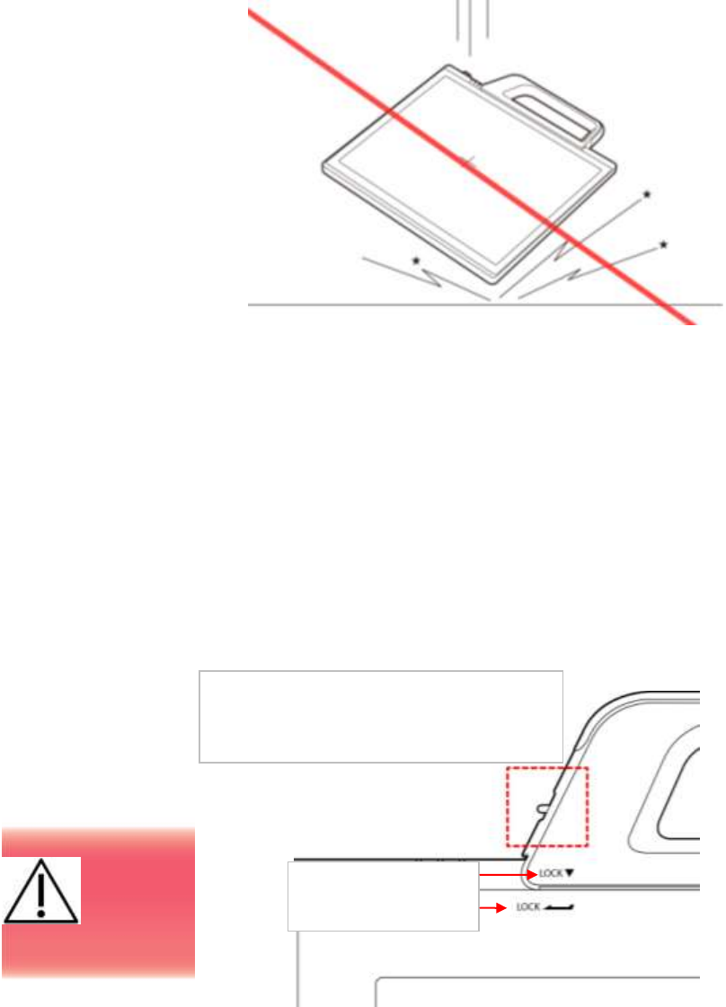
(2) Handle Assembly
※ Insert the handle always in the same
Please confirm lever position. When the
handle is locked, the lever should be
same position with the right picture.
Insert the handle in
the same direction
If the
handle is
not locked,
the detector can be
dropped.
14
(3) Before Exposure
Be sure to check the equipment daily and confirm that it works
properly.
Sudden heating of the room in cold areas will cause
condensation to form on the instrument. In this case, wait until
condensation disappears before performing exposure.
If the instrument is used with condensation formed on it,
problems may occur in the quality of the instrument. When an air-
conditioner is going to be used, be sure to raise/lower the
temperature gradually so that a difference in temperature in the
room and in the instrument does not occur, to prevent forming of
condensation.
(4) During Exposure
Do not use the detector near devices generating a strong
magnetic field. Doing so may produce image noise or artifacts.
Do not apply excessive weight to the sensor unit. Otherwise, the
sensor may be damaged.
(5) Disinfection and Cleaning
Do not spray the detector directly with disinfectants or detergents.
Do not use anything other than neutral detergent for cleaning the
cover of the instrument. Otherwise, the coating will be corroded.
(6) Others
Be sure to reconnect the cables to the proper connectors.
Otherwise, the instrument may malfunction or may be damaged.

15
3. Technical Features
(1) Mechanical Features
Size
385 x 320 x 18 mm
Weight
3.2 kg (incl. Battery, not incl. handle)
Encapsulation Material
Mg
Window Material
Carbon fiber plate
(2) Electrical Features
Detector
Sensor Type
Amorphous Silicon with TFT (Single Panel)
X-ray Converter
Gd2O2S:Tb
Total Pixel Number
2560 × 2048 pixels
Total Pixel Area
325.1 x 260.1 mm
Effective Pixel Number
2520 × 2008 pixels
Effective Pixel Area
320 x 255 mm
Pixel Pitch
127 μm
Limiting Resolution
Max. 3.9 lp/mm
Energy Range
40 - 150 kV
A/D Conversion
14 / 16 bits
Preview Time
< 2.0 sec (wired)
< 5.0 sec (wireless)
Data Interface
Gigabit Ethernet
Wi-Fi (802.11a/g/n)
Table 1: Product specification
Under RQA5 condition (70kVp, 21mmAl)
Preview time is not included post-processing time
16
Battery
Size
232.2 x 130.9 x 7 mm
Weight
Typ. 0.3 kg
Input
12.6 VDC
Output
11.1 VDC
Charging time
Typ. 3 hours
Capacity
Typ. 3400 mAh
The number of times
being acquired image
180 images
(@general x-ray exposure condition)
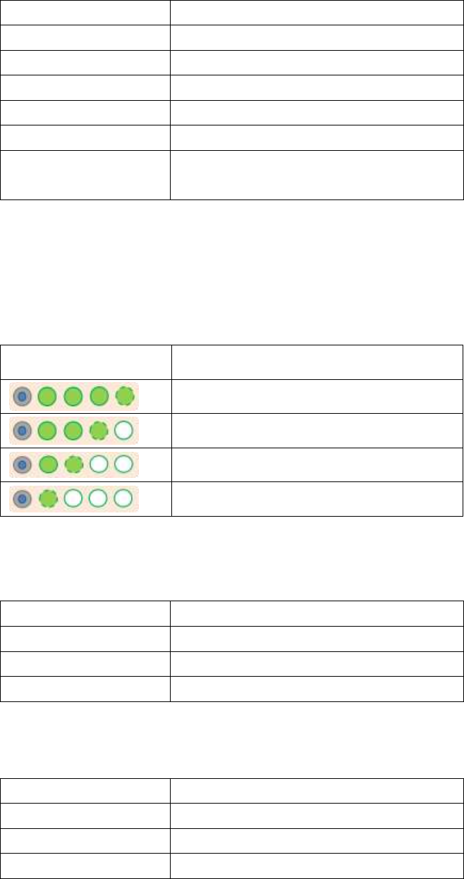
The Battery level can be displayed on the LED status of battery.
If the battery level goes down under 25%, please charge the
battery
Display
Battery level
75~100 %
50~75 %
25~50 %
0~25 %
Charger
Size
267.5 x 100 x 77 mm
Weight
Typ. 0.7 kg
Input
20 VDC
Output
12.6 VDC
Adapter
Size
160 x 76 x 43.7mm (cable length: 1.28m)
Weight
Typ. 0.8 kg
Input
100~240 VAC, 47~63 Hz, 1.4~0.6A
Output
20 VDC, Max 6.0A

17
Wireless Spec
Standard
802.11a/g/n compliance
Without DFS (5.25GH to 5.35GHz and 5.47
to 5.725) Band
Peak Rate
300Mbps
Frequency
2.4 GHz / 5 GHz
Bandwidth
20MHz/40MHz
MIMO
2x2
※ Maximum wireless signal rate derived from IEEE standard specifications.
Actual data throughput will Network conditions and environmental factors,
including volume of network traffic, building materials and construction, and
network overhead, lower actual data throughput rate.
※Recommended Maximum operable distance : 10m (From the Access Point)
※Wireless Module and Wireless Antenna
※Wireless antennas: The module adopts the latest 802.11n Dual-Band
technology (2.4Ghz and 5Ghz).
The transmitter of the module is powered by host equipment (Detector). The
antennas are 2 printed-dipole antennas.
※Wireless module: The SparkLAN WPEA-121N 802.11 a/b/g/n half mini PCI-e
module is implemented. It supports 2T2R (2 transmit 2 receive) MIMO
technology, which delivers throughput up to 300Mbps. 1012WGB in the RF
module does not use DFS band.

18
(3) Environmental requirement
Item
Min
Typ.
Max.
Unit
Note
Temperature
5
40
℃
Humidity
30
75
%
H.R.
Pressure
70
106
kPa
Vibrations
(Wrapping
condition)
2G
(8G)
10-150Hz,
10Sweeps,
1min/Octa
ve, XYZ
axis
19
(4) PC Requirements
Processor: At least Intel Pentium IV HT with 2.8GHz, Intel
Core Duo / Core 2 or comparable AMD Dual Core processor
At least 3GB of RAM requirement (4GB for 32 BITS OS and
8GB for 64 BITS OS recommended)
At least 500GB for application and archiving. Recommended
500GB for applications and secondary drive of 1TB for image
archiving..
Dual 10/100/1000 network card system required. One for
network (Internet) and one for the DR Panel communication
Graphics card / monitor: Resolution of at least 1,600 x 900 for
desktop and 1366 x 768 for laptop. For diagnostics purpose
we recommend 1920 x 1080 resolution (2 mega pixels)
monitor
Microsoft® Windows 7 32BIT/64BIT
No antivirus except for Microsoft® Security Essentials.
20
4. Installation
The Detector is composed of sensitive electronic parts and
components. It is recommended to use the product in a clean
place and to exercise caution to ensure that it is not affected by
dust or liquids. It is recommended to Use a dry and soft cloth to
clean the detector housing.
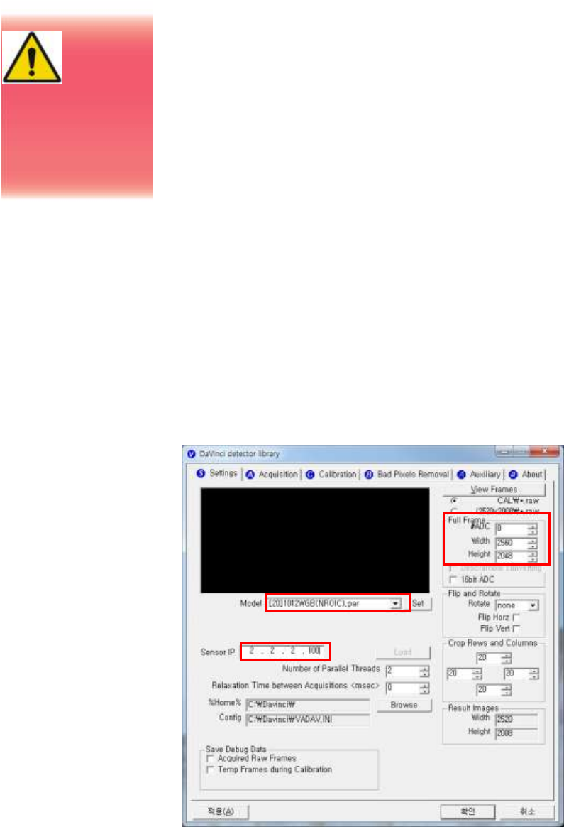
(1) Program setup
To acquire images, run _vadav.lnk program.
Please set the following figures
Detector’s IP : Wireless-2.2.2.100, Wired-2.2.2.101
Detector‘s number of ADC : 0
Detector’s size of image : 2560 x 2080
Portable
Imaging
processing
unit must be
installed in a way
that enables the
user to achieve
optimal use
21
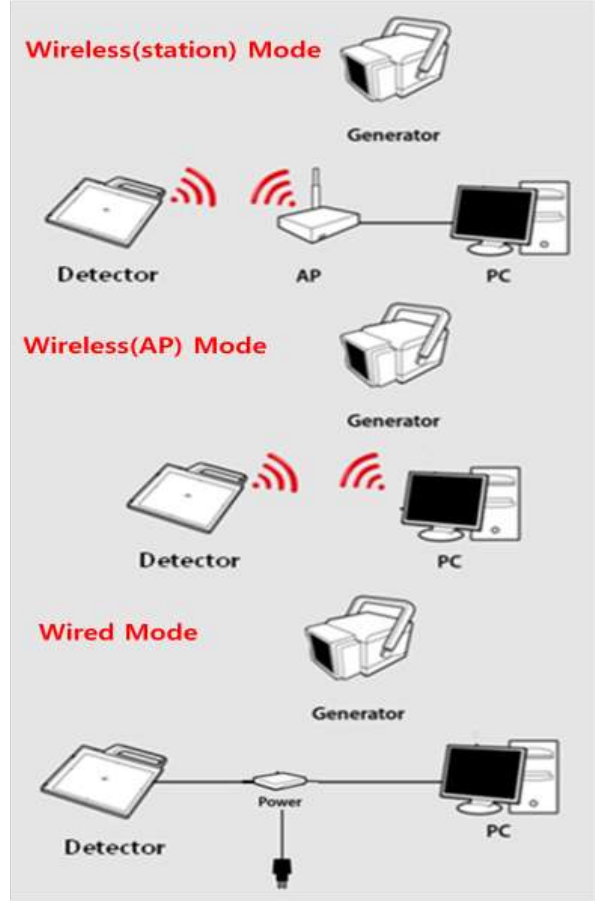
(2) Connection (Manual Trigger)
Power Connection
A. Connect the battery pack or power cable to the equipment.
* In wired mode, the frame ground is necessary.
* When you use the detector with wired mode, the WLAN
function is automatically off.
22
※ Be sure to sure only the dedicated battery pack, RB37WH
for 1012WGB.
Wireless Communication
A. AP Router(Line sharer) setting
- SSID : Griffon
- Internal network
- IP address : 2.2.2.1
- Subnet mask : 255.255.255.0
- Dynamic IP allocation range : 2.2.2.2 ~ 2.2.2.254
- Pre-Shared Key(Password) : project302
- Authentication methods : WPAPSK or WPA2PSK
- Password methods : TKIP/AES
- AP IP : 2.2.2.1
- Channel (Frequency)
- Avoid crowded channel
(Using wireless detector under crowded channel result
in low performance)
- If available, Use ‘Auto-Channel Selection’ function
of router to find optimal channel
B. Reception Indicator
Link LED flickering
23
Blink Speed : Slow – Low link quality
Fast – High link quality
C. Checking Link Quality & Battery Remain
- After wireless connection is established, perform ‘Get Bright’
in ‘Calibration’ tap.
- Check the value named ‘Wireless Signal’ in black log screen.
Wireless Signal = Link Quality (Max. 100)
- Check the value named ‘Battery Remain’ in black log screen.
Battery Remain = Battery Remain(Max. 100)
The value ‘Wireless
Signal’ will be
displayed here
24
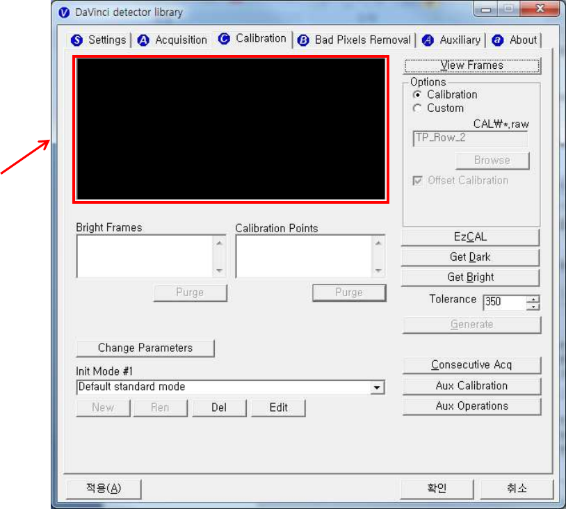
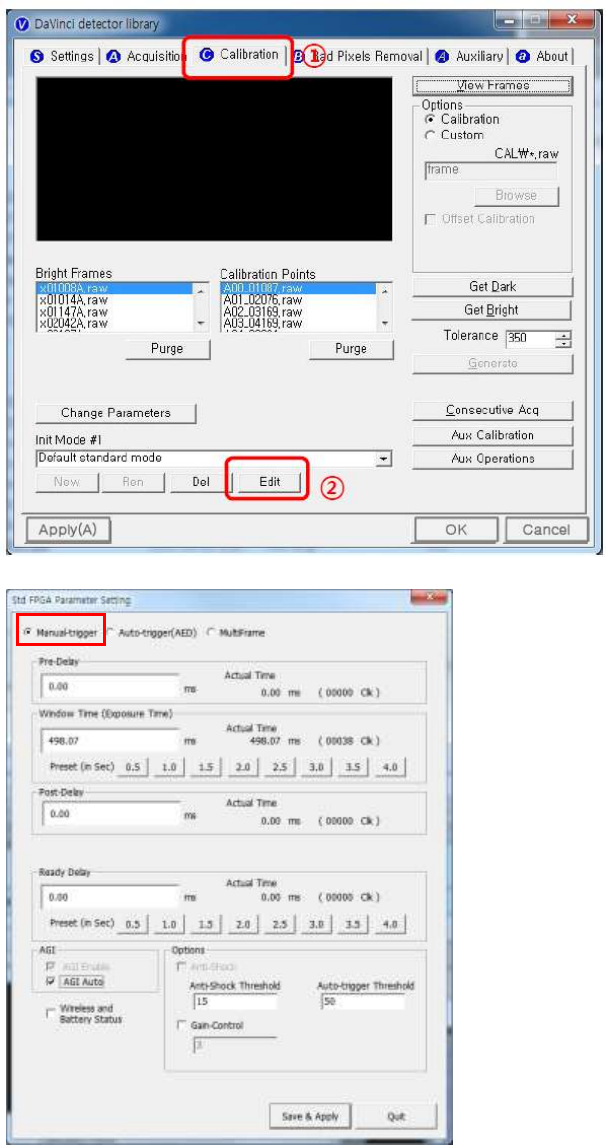
Software Setting (Manual trigger)
25
Trigger Connection
A. Connect the P-interface cable or trigger cable to the generator
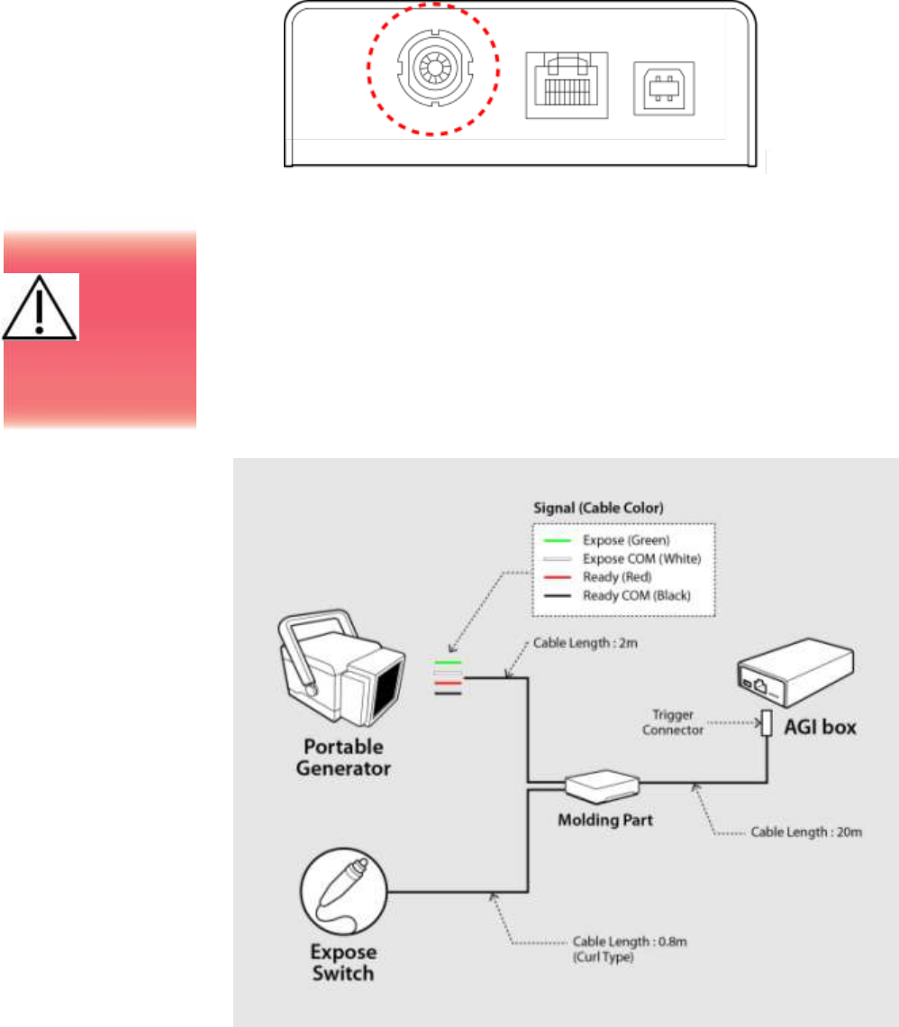
X-ray Generator Connection
A. Mode 1 : P-interface cable mode
Connect the P-interface cable between the AGI box and X-ray
generator.
Operating description
Make
assurance
doubly sure
SIGNAL RATING
before connection.
26
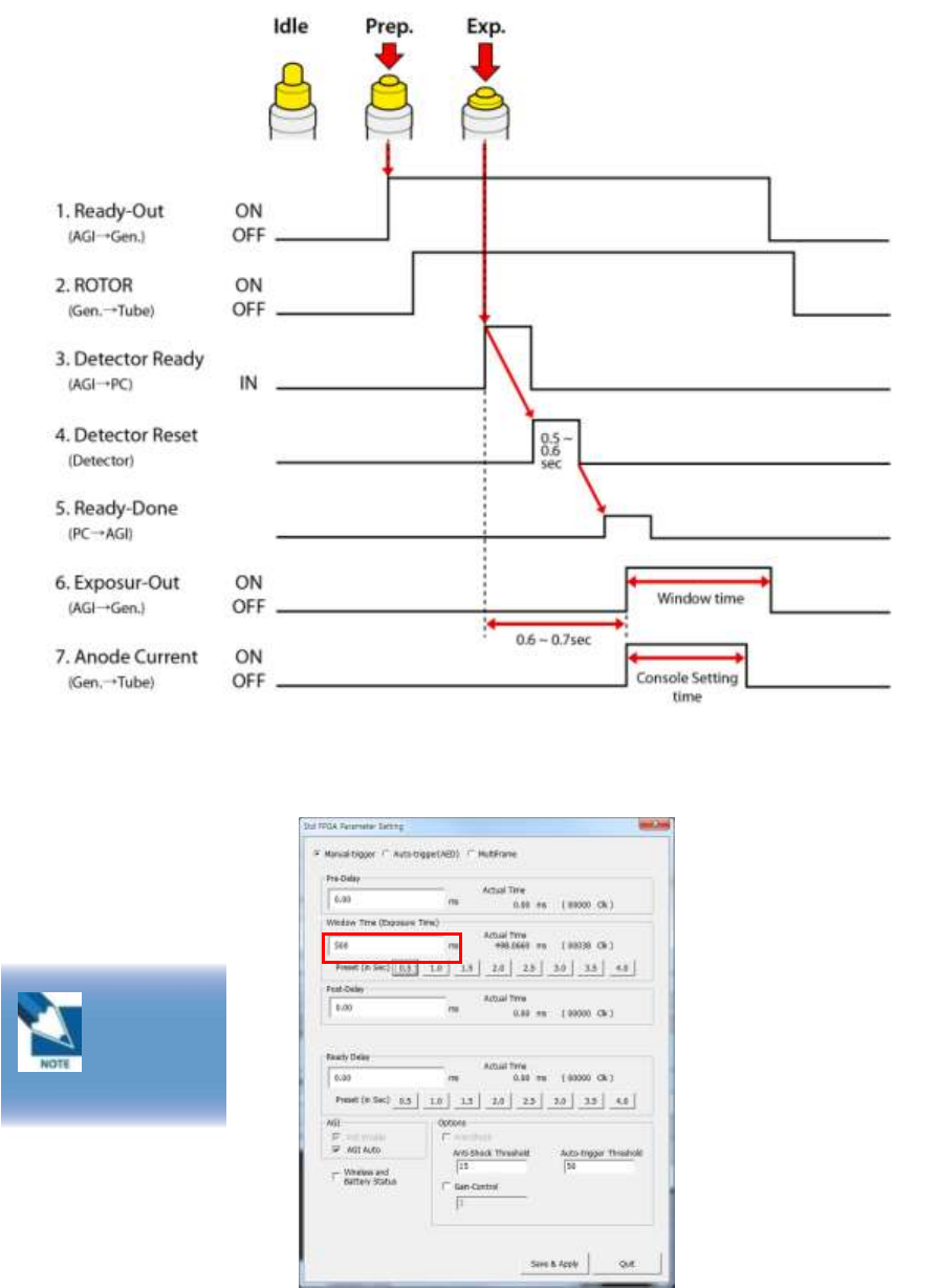
The window time can be changed. Refer to the following pictures
Exposure
Time
500ms is
designate to 0.5sec
27
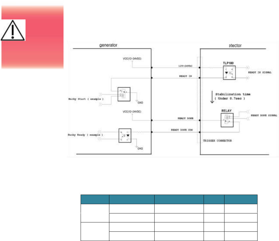
B. Mode 2 : Trigger cable mode
Connect the Trigger cable between the X-ray enable connector of
AGI with X-ray generator.
Figure 8: <2nd example> wiring for the interface between portable generator & detector
Connection description
Signal
New Label
Old Label
Color
Input / Output
READY IN
12V~24VDC
R.E.C. +12-24V
Red
Input
READY IN
Ready Input Signal
Black
Input
READY
DONE
READY DONE
Exposure Output SW1
Green
Output
READY DONE COM
Exposure Output SW2
Blue
Output
Make
assurance
doubly sure
SIGNAL RATING
before connection.
AGI
Box
28
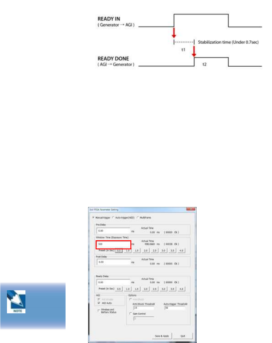
Operating description
t1: It will be occurred when exposure switch is pushed completely
after.
t2: Window time of detector is varying 0 sec ~ 15 sec. which can
be control by S/W.
Expose relay switch ON time (Window Time) and X-ray
exposure time must be same.
t2 time can be control by S/W
The window time can be changed. Refer to the following pictures
Exposure
Time
500ms is
designate to 0.5sec
29
(3) Connection (Auto Trigger)
Power Connection
A. Connect the battery pack or power cable to the equipment.
* In wired mode, the frame ground is necessary.
※ Be sure to sure only the dedicated battery pack, RB37WH
for 1012WGB.
30
Wireless Communication
A. AP Router(Line sharer) setting
- SSID : Griffon
- Internal network
- IP address : 2.2.2.1
- Subnet mask : 255.255.255.0
- Dynamic IP allocation range : 2.2.2.2 ~ 2.2.2.254
- Pre-Shared Key(Password) : project302
- Authentication methods : WPAPSK or WPA2PSK
- Password methods : TKIP/AES
- AP IP : 2.2.2.1
- Channel (Frequency)
- Avoid crowded channel
(Using wireless detector under crowded channel result
in low performance)
- If available, Use ‘Auto-Channel Selection’ function
of router to find optimal channel
B. Reception Indicator
Link LED flickering
Blink Speed : Slow – Low link quality
Fast – High link quality
C. Checking Link Quality & Battery Remain
31
- After wireless connection is established, perform ‘Get Bright’
in ‘Calibration’ tap.
- Check the value named ‘Wireless Signal’ in black log screen.
Wireless Signal = Link Quality (Max. 100)
- Check the value named ‘Battery Remain’ in black log screen.
Battery Remain = Battery Remain(Max. 100)
The value ‘Wireless
Signal’ will be
displayed here
32
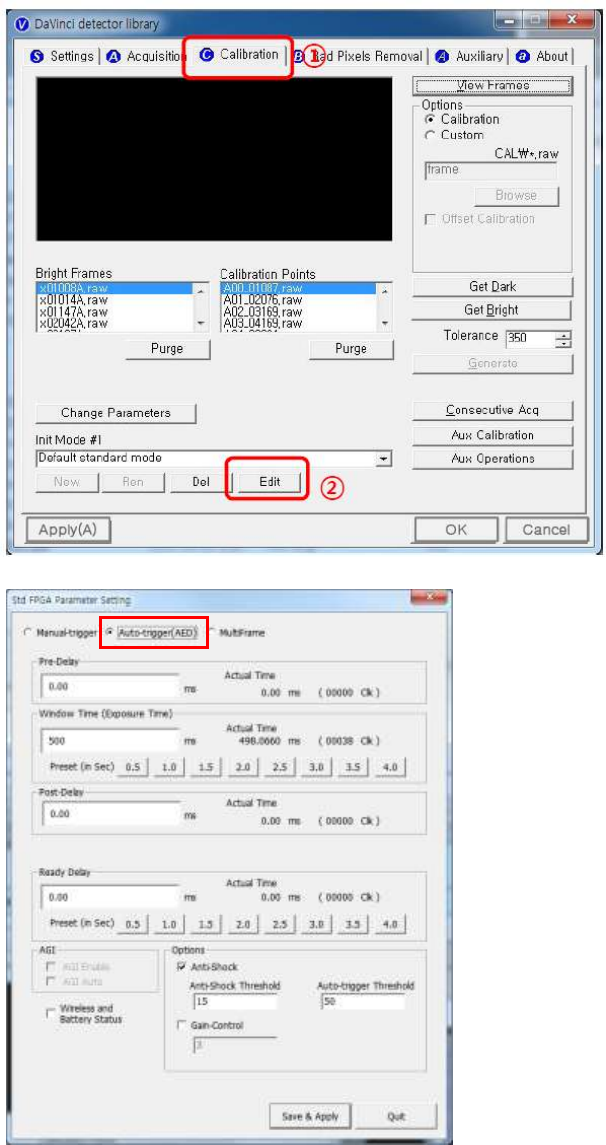
Software Setting (Auto trigger)
33
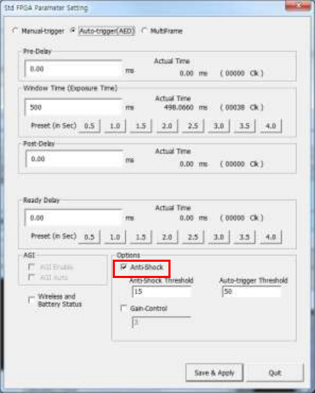
Important Note
In AUTO TRIGGER MODE, the trigger will be forced not to
acquire images when detector senses vibration or shock.
In READY mode, Detector will automatically switch to WAIT
mode when detector senses vibration or shock, so that user won’t
acquire images in WAIT mode although X-ray exposure applies.
WAIT mode switches back to READY mode after 2-3 seconds.
If you don’t want to use ANTI-SHOCK FUNCTION, please click
OPTION “Anti-shock
IF you don’t use ANTI-SHOCK FUNCTION, you are able to get
images regardless detector senses vibration or shock. However,
you should keep in mind there is also a possibility images can be
acquired by vibration or shock without X-ray exposure.
34
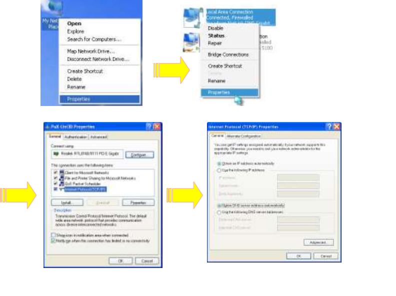
(4) IP set up
Wired & Station mode
[My Network Places] → [Properties] → [Local Area Connection]
→ [Properties] → [Internet Protocol (TCP/IP)]
→ [Use the following IP address]
IP address: Obtain an IP address automatically
IP address : Obtain an IP address automatically
35
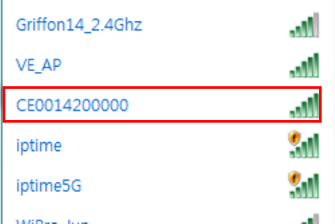
AP mode
[Search wireless network] → [Connect detector serial Number] →
[Input Password]
(* Password: Project302)
→ [Wireless connection IP address setting: Obtain an IP address
automatically]
(5) Checking Connection
Check LED on the detector & power supply
Ping test: [Start] →[Run] →ping -t 2.2.2.100

36
5. Calibration
(1) General Principle
Notation
Calibration can be done by image acquisition S/W. The gain-
offset correction (under calibration) will be done with one dark, at
least one bright and object frame.
Parameter
Description
Offset
Dark image, acquired image without X-ray exposure
Bright
Acquired image with X-ray exposure
Object
Bright image with object, will be calibrated
Gain
Gain of imaging system, offset subtracted image
Offset correction
Offset subtract
Gain correction
Compensate gain variance of pixel
Table 4: Parameter description
X-ray
detector
should be
used at stable state
within driving
temperature range.
Acquire the X-ray
images after power
on and 30 minutes
warming up to
obtain high quality
images.
37
Bright Calibration Point
To gain correction, bright frame and dark frame should be
acquired. The dark frame is needed only one frame. The bright
frame is recommended to be acquired more than 2 different
levels of median values of bright frames. The X-ray source
condition will be recommended the tube energy level of 70kVp
with variable tube current and exposure time. To acquire at least
2 frames at same condition will be recommended. The median
values of bright frames are below.
(Additional 21mm Al filter is recommended for calibration)
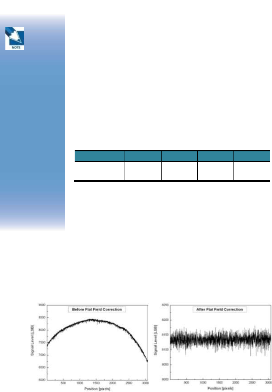
The Purpose of Bright Calibration
The center of the non calibrated image is brighter than the edge
due to hill effect of X-ray exposure. Generally, the intensity of X-
ray flux at center region of exposed area is higher than
surroundings due to the X-ray expose like cone shape. A
calibration process is used to compensate for this effect.
Generally, called it ‘Flat Field Correction’ (Bright calibration).
Figure 8: Comparison of flat field correction processing
Point
1
2
3
4
Median Value [LSB
500 ~
1000
2900 ~
3400
6200~
6700
9500 ~
10000
Table 5 : Median value
The
calibration
range of
bright is can be
select by which
exposure level is
maximum level that
user want to use. If
the maximum level
of user want to use
is ‘6500’ in this case
the level is
contained in Bright
point of ‘3’(refer
‘Table 5 : Median
value’). The meaning
is you don’t have to
make bright point
for ‘4’(In this case, it
will be does not
working if you get
image on higher
level than maximum
bright point.)
38
(2) Calibration
Describe the calibration step by step.
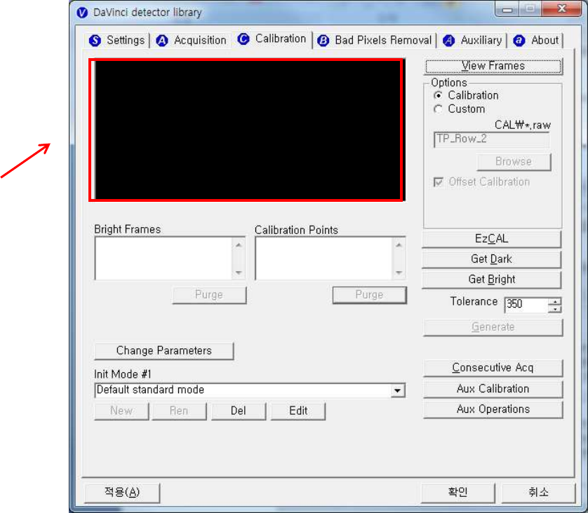
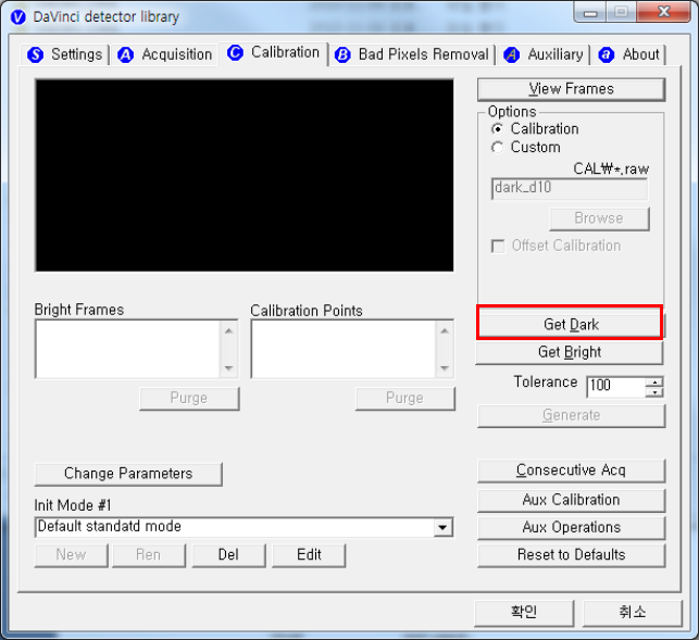
1st Step
Click on the “Get Dark” button. The acquired dark frame
“dark.raw” will be generated in the “\cal\” folder.
Figure 9: Get dark
39
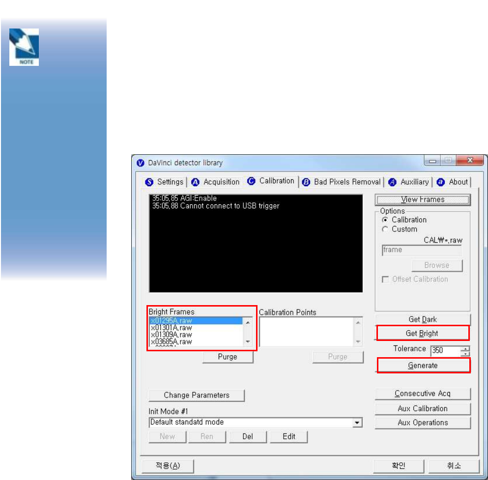
2nd Step
Push “Get Bright” button at different four of X-ray condition. The
X-ray condition should be set or tested before, same as the level
of ‘1.2’. Push “Get Bright” button at least 2 times at same
condition, and then the offset subtracted bright (gain) is
generated which of filename is “xNNNNNA.raw(Refer to NOTE)
Figure 10: Get bright.
Click
button [Get
Bright]. It
will produce frame
with name %CAL%
xNNNNNA.raw,
where NNNNN is
median pixel’s value
within current
image borders after
offset calibration
(cut frame edges are
never used during
calibration). Suffix
‘A’ (it also could be
‘B’,’C’ etc) avoids
casual coincidence
of file names.
40
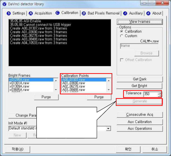
3rd step
After 2nd step, the “Generate” button will be activated. Click the
button “Generate”, and then calibration point will be generated
which of file name is “A ‘# of point’_ ‘median value of generated
point’” like file of bright frame. The acquired bright frames within
tolerance value which is variance of median level of acquired
bright frames will be averaged and generated to a calibration
point. The tolerance value can be edited.
Figure 11: Generate
After making
calibration point the
“Generate” button will
be disabling.
41
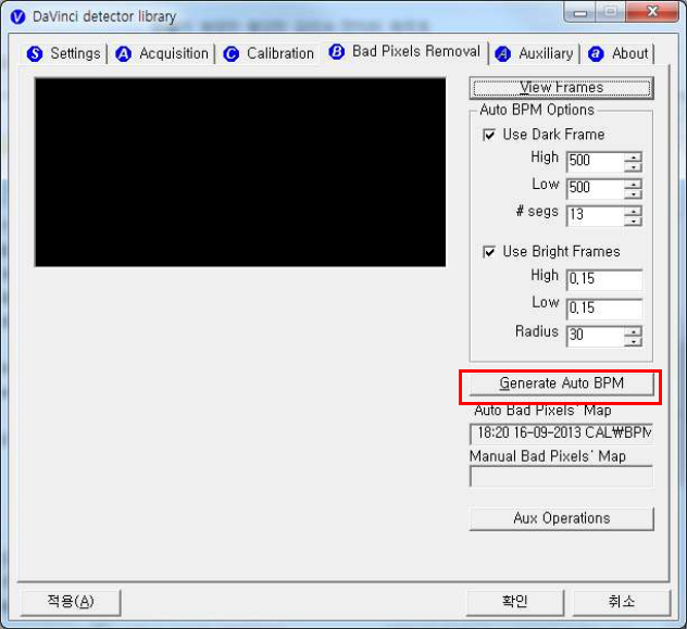
4th step
After 3rd step, Change Bad Pixels Removal Tab, Click the button
“Generate Auto BPM”, and then Defect Map will be generated
which of file name is “BPM.raw “ at the “\cal\” folder.
Figure 12: Bad pixels removal
42
5th step
For additional Defect correction, if “BPMM.raw” is existed at the
install CD, copy to the “\cal\” folder.
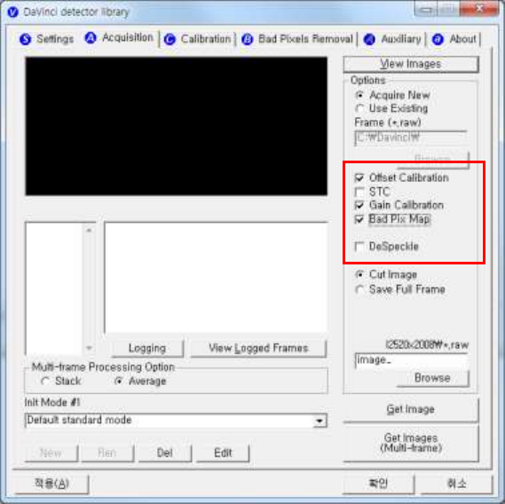
6th step
On Acquisition Tab. Check the box “Offset Calibration”, “Gain
Calibration”, “Bad Pix Map” for activate to each calibration and
Bad Pixels Removal. Otherwise, it will does not working when
going to pre-processing .
Figure13: Application of calibration
43
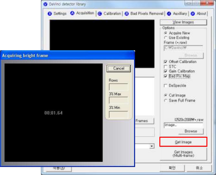
6. Image Acquisition Test
(1) Get Image
On Acquisition tab, click the “Get Image” button to get image.
After click the button, you can see pop-up window, which is
display window time and process of acquiring image.
Figure 14: Get image
44
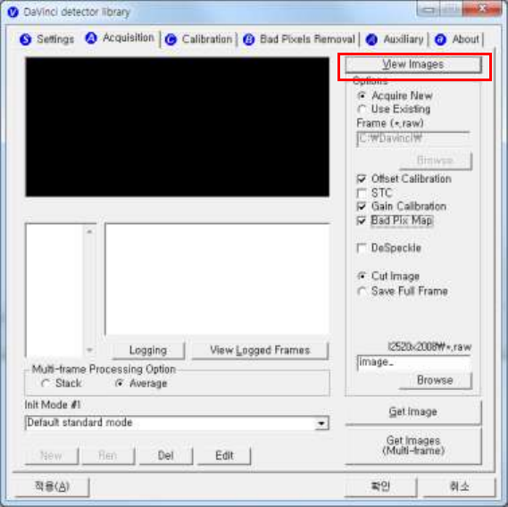
(2) View Images
Frame- and image-files have extension “raw” and contain pixel
data in signed 16-bits little-endian format. One could view those
files in Photoshop or another image editor.
Figure 15: View images
45
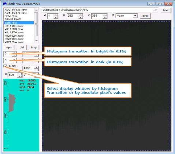
Common controls and displayed statistics
Figure 16: Description of viewer 1
Pixel_Min – minimum pixel value in frame- or image- data
Pixel_Max – maximum pixel value
Pixel_Black – if a pixel ≤ Pixel_Black then it is displayed as
black (RGB 0, 0, 0)
Pixel_White – if a pixel ≥ Pixel_Black then it is displayed as
black (RGB 255, 255, 255)
46
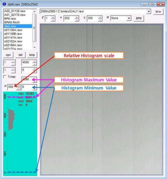
Histogram’s presentation
Relative Histogram Scale [H]=1000 means that that the distance
depicted as “H” on the drawing matches 1% of total number of
pixels. Respectively [H]=100 means that “H” matches 0.1% of
pixels and [H]=500 means that “H” matches 0.5% of pixels.
Figure 17: Description of histogram
47
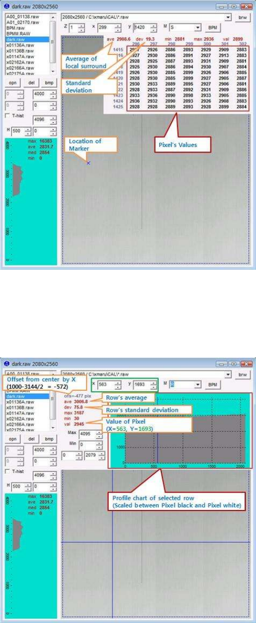
Marker type “S”
Displays local surround of selected location
Figure184: Description of marker type "S"
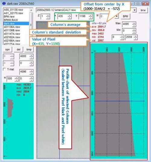
Marker type “R”
Display profile chart of a row.
Figure 19: Description of marker type "R"
48
Marker type “C”
Display profile chart of a column.
Figure 20: Description of marker type "C"
49
7. Operation
(1) Recommend
X-ray detector should be used at stable state within driving
temperature range.
Acquire the X-ray images after power on and 30 minutes
warming up to obtain high quality images.
The calibration should be performed every 6 months
(2) Switching power on / off
All connection should be done, before turn on the power.
Press the power button by more than 3 sec, when power
on/off.
The green light of the LED indicator on the detector is on, the
detector power is on.
The green light of the LED indicator on the detector is blinking,
the detector is getting prepared to work and initialize.
After power off, separate the battery.
(3) Storage
Store the sensor unit in clean and dry place. Ensure that storage
place should be not affected by dust or liquids.
50
8. Radio Frequency compliance
(1) FCC Notice (U.S.A)
Test standards
- 47CFR Part 15.107 (b) / 47CFR Part 15.109 (g) Class A.
- FCC Part 15 C Section 15.247, Operation within the bands
902–928 MHz, 2400–2483.5 MHz, and 5725–5850 MHz
- FCC Part 15 C Section 15.407, Operation within the bands
902–928 MHz, 2400–2483.5 MHz, and 5725–5850 MHz
FCC ID: QIIRY1012WGB
5.15- 5.25 GHz band is restricted to indoor operations only.
Host device of the approved module shall be marked with the following
item:
Compliance with FCC requirement 15.407(c)
Data transmission is always initiated by software, which is the passed
down through the MAC, through the digital and analog baseband, and
finally to the RF chip. Several special packets are initiated by the MAC.
These are the only ways the digital baseband portion will turn on the RF
transmitter, which it then turns off at the end of the packet. Therefore,
the transmitter will be on only while one of the aforementioned packets
is being transmitted. In other words, this device automatically
discontinues transmission in case of either absence of information to
transmit or operational failure.
This device complies with part 15 of the FCC Rules. Operation is
subject to the following two conditions: (1) This device may not cause
harmful interference, and (2) this device must accept any interference
received, including interference that may cause undesired operation.
51
FCC CAUTION
Changes or modifications not expressly approved by the party
responsible for compliance could void the user’s authority to operate the
equipment. This transmitter must not be co-located or operated in
conjunction with any other antenna or transmitter.
When installing it in a mobile equipment
This equipment complies with FCC radiation exposure limits set forth for
an uncontrolled environment and meets the FCC radio frequency (RF)
Exposure Guidelines in Supplement C to OET65. This equipment has
very low levels of RF energy that it deemed to comply without maximum
permissive exposure evaluation (MPE). But it is desirable that it should
be installed and operated keeping the radiator at least 20cm or more
away from person’s body (excluding extremities: hands, wrists, feet and
ankles).
When you use the detector with wire mode, the wireless function is
automatically off.
52
(2) IC Notice (CANADA)
Test standards
- ICES-003 Issue 4
- IC RSS-210 Issue 7, Operation within the bands
902–928MHz, 2400–2483.5 MHz, and 5725–5850 MHz
- IC RSS-210 Issue 7, Operation within the bands 902–928 MHz,
2400–2483.5 MHz, and 5725–5850 MHz
IC: 10742A-1012WGB
This Class A digital apparatus complies with Canadian ICES-003
This device complies with Industry Canada licence-exempt RSS
standard(s). Operation is subject to the following two conditions: (1) this
device may not cause interference, and (2) this device must accept any
interference, including interference that may cause undesired operation
of the device.
Le present appareil est conforme aux CNR d'Industrie Canada
applicables aux appareils radio exempts de licence. L'exploitation est
autorisee aux deux conditions suivantes : (1) l'appareil ne doit pas
produire de brouillage, et (2) l'utilisateur de l'appareil doit accepter tout
brouillage radioelectrique subi, meme si le brouillage est susceptible
d'en compromettre le fonctionnement.
53
(3) R&TTE Notice (European Union)
Test standards
- EN 62311
- ETSI EN 301 489-1
- ETSI EN 301 489-17
- ETSI EN 300 328
- ETSI EN 301 893

54
9. Maintenance
(1) Maintenance
Maintenance of the detector should be done by an authorized
service provider
If the Detector Panel is defective, the detector will be
returned as is to the manufacturer for repair
Clean the equipment with a dry soft cloth, or a soft cloth
lightly moistened with mild detergent solution. Do not use any
type of solvent, such as benzene
This equipment and accessories are to be disposed of safely
after the life span of them and national regulation must be
observed.
For safety reasons, be sure to inspect the instrument before
using it. In addition, carry out a regular inspection at least
once a year.
Arrange the detector and power supply link cable to prevent
the damage of the cable’s rubber tube. For example, do not
press the cable under the legs of the table or the people.
If you need more information, please contact to the Rayence
C/S team, they will provide it.
(2) Cleaning
Cover
Clean the cover by the left warning box, if it is dirty.
CFRP of Detector
Wipe the CFRP plate of the sensor unit with ethanol or
glutaraldehyde solution. If you are using disinfectant other than
those specified above, or you are mixing another disinfectant with
When the
instrument
is going to
be cleaned, be sure
to turn OFF the
power of each
instrument, and
unplug the power
cable from the AC
outlet. Never use
benzene, thinner or
any other
flammable cleaning
agents. Otherwise,
fire or electric shock
may result.

55
ethanol, please also consult a specialist, because they may harm
the CFRP plate.
(3) Inspection
In order to ensure that the instrument is used safely and normally,
please be sure to inspect the instrument before use. If any
problem is found during the inspection, please take measures
indicated in this chapter. If problem still cannot be corrected,
please contact Rayence representative or distributor. It is
recommended that a record of the inspection be kept by making
copies of the check lists in this section, or making a separate
check list.
Inspection chart
Inspection
User
Vendor
Cycle
Check that cables are not
damaged or cover of cables is
not torn
O
Daily
Check that the plugs and locks
of connectors are not loose
O
Daily
Check that the cover or parts
are not damaged and not loose
O
Daily
Check the LED indicator
O
Daily
Check the bad pixel map
O
Half year
Check the performance of the
instrument by performing
exposures using a phantom or a
resolution chart
O
Yearly
For
safety
reasons, be
sure to turn OFF the
power of the
detector when the
following
inspections are
going to be
performed.
Otherwise, it may
result in electric
shock.
56
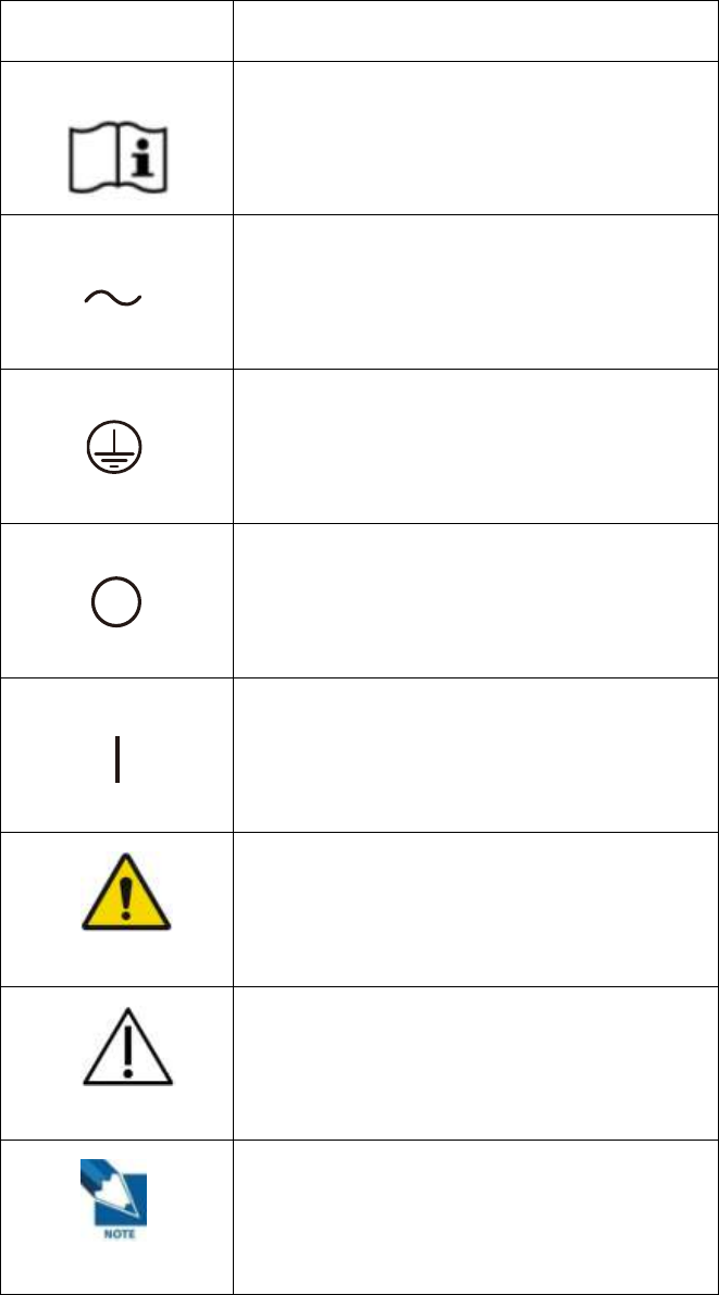
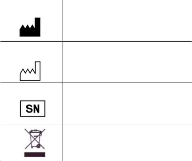
(4) Marking and labeling symbols
Symbols
Meaning
Caution : “Attention, see instructions for use”
Alternate current
Protective earth (Ground)
Off (power : disconnect from the main switch)
On (power : connect to the main switch)
Warning
Caution
Note
57
Manufacturer
Date of manufacture
Serial number
WEEE : Waste Electrical and Electronic
Equipment
Figure 21: Labeling symbols
58
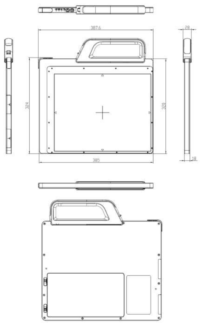
Appendix
Dimension [unit : mm]

59
Rayence Co., Ltd.
14, Samsung 1-ro 1-gil, Hwaseong-si, Gyeonggi-do, Korea
www.rayence.com
Rayence Co., Ltd.
14, Samsung 1-ro 1-gil, Hwaseong-si, Gyeonggi-do, Korea
www.rayence.com