Raymarine C Series Reference Guide 81221_4
C Series to the manual 663f13aa-fb66-477a-9751-c7f680526f83
2014-12-13
: Raymarine Raymarine-C-Series-Reference-Guide-125934 raymarine-c-series-reference-guide-125934 raymarine pdf
Open the PDF directly: View PDF ![]() .
.
Page Count: 244 [warning: Documents this large are best viewed by clicking the View PDF Link!]
C-Series Display
Reference Manual
Document number: 81221_4
Date: March 2006
81221_4.book Page i Tuesday, February 28, 2006 5:24 PM

E-Series Reference Manual
Trademarks and registered trademarks
Autohelm, HSB, Raymarine, RayTech Navigator, Sail Pilot, SeaTalk and Sportpilot are registered
trademarks of Raymarine Limited. Apelco is a registered trademark of Raymarine Holdings Limited
(registered in all major marketing territories).
AST, Autoadapt, Auto GST, Autoseastate, Autotrim, Bidata, Marine Intelligence, Maxiview, On Board,
Raychart, Raynav, Raypilot, Raystar, ST40, ST60, Seaclutter, Smart Route, Tridata and Waypoint
Navigation are trademarks of Raymarine Limited.
Navionics is a registered trademark of Navionics Company, Italy.
All other product names are trademarks or registered trademarks of their respective owners.
Software in this product is based in part on the work of the Independent JPEG Group.
Contents of this handbook ©Raymarine UK 2006.
81221_4.book Page ii Tuesday, February 28, 2006 5:24 PM
Important information i
Important Information
Intended use
The display units detailed in this handbook may form part of marine navigational radar
system or GPS system intended for use on (non-IMO/SOLAS class) leisure vessels or
small workboats.
This handbook contains important information on the operation and maintenance of
your C-Series Display. To get the best results in operation and performance, please take
the time to read this handbook thoroughly.
For full details of installation and system integration, please refer to the C-Series
Installation Guide supplied with the display.
Safety notices
WARNING:Navigation Aid
This device is intended to be used as an aid to navigation. Its
accuracy can be affected by many factors, including equipment
failure or defects, environmental conditions and incorrect
handling or use. It is the user’s responsibility to exercise common
prudence and navigational judgement. This device should not be
relied upon as a substitute for such prudence and judgement.
WARNING:Product installation
This equipment must be installed in accordance with the
instructions in the C-Series System Installation Guide. Failure to do
so could result in poor product performance, personal injury and/
or damage to the vessel.
WARNING:High voltage
The display unit and scanner unit contain high voltages.
Adjustments require specialized service procedures and tools only
available to qualified service technicians - there are no user
serviceable parts or adjustments. The operator should never
remove the display unit cover or attempt to service the
equipment.
WARNING:Electromagnetic energy
The radar scanner transmits electromagnetic energy. Ensure that
the scanner has been installed according to the recommendations
given in the relevant scanner handbook. Avoid looking directly at
the antenna.
81221_4.book Page i Tuesday, February 28, 2006 5:24 PM

ii C-Series Display Reference Manual
WARNING:Fishfinder sounder module
Removing the transducer cable from the rear of the fishfinder
sounder module whilst it is switched on can cause sparks. Only
remove the transducer cable after power has been switched off.
Ensure that the sounder module is mounted where it is well
ventilated and in an area free from flammable vapors.
CAUTION: Water Ingress
To prevent the ingress of water and consequent damage to the display,
ensure that the chart card door is firmly closed. This can be confirmed by an
audible click.
CAUTION: CompactFlash Cards
• Removing the CompactFlash card whilst information is being written to or
read from it may cause damage to the card and loss of all data. Use the
proper procedure detailed on
page 18
to remove the card.
• Do not save data (waypoints, routes etc.) to a Navionics card as the charts
may be overwritten. When archiving use a different CompactFlash card.
• DO NOT use a metallic instrument such as a screwdriver or pliers to help you
remove a card, as doing this can cause irreparable damage.
CAUTION: Global Positioning System Antenna
Do not connect or disconnect the GPS antenna from the display unit whilst
power is switched on. Doing this may result in irreparable damage.
CAUTION: UV Light
To provide protection against the damaging effects of UV light, it is advisable
to replace the sun cover provided when the display is not in use.
CAUTION: Cleaning the display
Take care when cleaning the display, to avoid damaging it:
(1) Do NOT wipe the display screen with a dry cloth, as this could scratch
the screen coating.
(2) Do NOT use acid, ammonia based or abrasive products.
Disclaimers
Electronic charts are an aid to navigation designed to facilitate the use of authorized
government charts, not to replace them. Only official government charts and notices to
mariners contain the current information needed for safe navigation. The Captain is
responsible for their prudent use. The C-Series and its charts do not therefore exclude
the user from carrying the required official charts and documents.
Raymarine does not warrant that this product is error-free or that it is compatible with
products manufactured by any person or entity other than Raymarine.
This product uses digital chart data, and electronic information from the Global
Positioning System (GPS) which may contain errors. Raymarine does not warrant the
accuracy of such information and you are advised that errors in such information may
cause the product to malfunction. Raymarine is not responsible for damages or injuries
caused by your use or inability to use the product, by the interaction of the product with
81221_4.book Page ii Tuesday, February 28, 2006 5:24 PM

Important information iii
products manufactured by others, or by errors in chart data or information utilized by
the product and supplied by third parties.
About this manual
This manual describes how to operate your C-Series display in conjunction with
Navionics cartography. It assumes that all peripheral equipment to be operated with it
is compatible and has been correctly installed.
This manual is intended for users of varying marine abilities, but assumes a general
level of knowledge of display use, nautical terminology and practices.
Technical accuracy
To the best of our knowledge, the technical information contained within this
handbook, was correct at the time of printing. However, Raymarine cannot accept
liability for any inaccuracies or omissions it may contain.
In addition, Raymarine’s policy of continuous product improvement may change
specifications without notice. As a result Raymarine cannot accept liability for any
differences between the product and this handbook.
Raymarine does not support after-sales or technical support for Navionics chart cards.
If you wish to file a report of an error or omission on a Navionics chart, please provide
the information to the Navionics web site at the link below:
http://www.navionics.com/DiscrepancyReports.asp
Raymarine does not necessarily support all the features in particular Navionics
cartography.
EMC conformance
All Raymarine equipment and accessories are designed to the best industry standards
for use in the recreational marine environment. Their design and manufacture
conforms to the appropriate Electromagnetic Compatibility (EMC) standards, but
correct installation is required to ensure that performance is not compromised.
Multi-media chart cards
To use your C-Series Display as a navigation aid, charts with the appropriate level of
detail for the geographic area you wish to navigate are required. The charts are
available in electronic format on Navionics Chart cards.
To check the current availability of Navionics® chart card types and the latest feature
sets, visit www.navionics.com or www.navionics.it.
To obtain Navionics cards, contact your local dealer or visit the Navionics web site.
81221_4.book Page iii Tuesday, February 28, 2006 5:24 PM

iv C-Series Display Reference Manual
Alternatively, anywhere in North America call Navionics toll-free on 1-800-848-5896
Outside of North America, contact your local dealer or Navionics SpA on:
Phone: (+39) 0584 961696 or Fax: (+39) 0584 961309)
When archiving data, Raymarine recommends that you only use SanDisk CF memory
cards. Other brands of CF memory card may not work in your C-Series Display.
Disposal
Waste Electrical and Electronic Equipment (WEEE) Directive
The WEEE Directive requires the recycling of waste electrical and electronic
equipment. Whilst the WEEE Directive does not apply to some of Raymarine’s
products, we support its requirements as part of our environmental policy and
we ask you to be aware of how you should dispose of this product.
The crossed-out wheelie bin symbol found on our products signifies that it should not
be disposed of in general waste or landfill.
Please contact your local dealer, national distributor or Raymarine Technical Services
for information on product disposal.
81221_4.book Page iv Tuesday, February 28, 2006 5:24 PM

Contents v
Contents
Chapter 1: Overview ..................................................................................................1
1.1 What will my C-Series integrate with? ..................................................................1
1.2 What can the C-Series Display do? ........................................................................2
1.3 The Simulator ........................................................................................................4
Chapter 2: General Operation ..................................................................................5
2.1 Introduction .......................................................................................................... 5
2.2 Powering the display ON/OFF ...............................................................................5
2.3 Using the controls .................................................................................................6
The control panel ............................................................................................6
Buttons and soft keys ......................................................................................7
The cursor ....................................................................................................... 8
2.4 Displaying applications .........................................................................................8
2.5 Additional screen information ..............................................................................9
2.6 Initial setup procedures ......................................................................................13
Setting the language, date/time format and units of measurement ..............13
Selecting a page set ......................................................................................14
Selecting an application page .......................................................................14
Selecting an application window ..................................................................15
Adjusting the display lighting ........................................................................16
2.7 Using CompactFlash cards ..................................................................................17
Cautions ........................................................................................................17
What are CompactFlash cards used for? .......................................................17
Inserting a card .............................................................................................18
Removing a card ...........................................................................................18
2.8 Managing data ...................................................................................................19
Writing/retrieving data to a CompactFlash card ............................................19
Sending and receiving information using a PC ..............................................22
Password protecting your waypoints ............................................................23
2.9 Emergencies and warnings .................................................................................26
Man Overboard (MOB) .................................................................................26
Alarms ..........................................................................................................27
81221_4.book Page v Tuesday, February 28, 2006 5:24 PM

vi C-Series Display Reference Manual
Chapter 3: Working with Waypoints .....................................................................29
3.1 What is a waypoint? ...........................................................................................29
3.2 How are waypoints represented? .......................................................................30
3.3 Placing a waypoint .............................................................................................31
3.4 Navigating to a waypoint ...................................................................................32
Start navigating to a waypoint ......................................................................32
Stop navigating to a waypoint ......................................................................33
3.5 Viewing waypoint information ...........................................................................33
3.6 Editing a waypoint ..............................................................................................34
Changing waypoint details ...........................................................................35
Moving a waypoint .......................................................................................35
Erasing a waypoint(s) ....................................................................................36
Changing the default symbol or group ..........................................................37
3.7 Sorting the waypoint list .....................................................................................38
3.8 Organising waypoints into groups ......................................................................38
Displaying the waypoint group list ................................................................38
Making a new waypoint group .....................................................................39
Moving waypoints between groups ..............................................................39
Renaming an existing group .........................................................................40
Erasing a group .............................................................................................41
3.9 Controlling waypoint display ..............................................................................41
Show/hide waypoint names ..........................................................................41
Showing/hiding waypoint symbols ...............................................................42
Showing/hiding waypoint groups .................................................................42
Chapter 4: Using the Chart ......................................................................................43
4.1 Important ...........................................................................................................43
Safety ............................................................................................................43
Chart functionality ........................................................................................43
Chart cards ....................................................................................................44
4.2 Uses of the chart application ..............................................................................44
4.3 Viewing the chart ................................................................................................45
4.4 The chart display .................................................................................................45
4.5 Where am I on the chart? ....................................................................................46
4.6 Moving around the chart ....................................................................................46
4.7 Additional information on the chart ...................................................................47
81221_4.book Page vi Tuesday, February 28, 2006 5:24 PM

Contents vii
Displaying details of objects and features .....................................................48
Finding nearby features and services ............................................................48
Displaying details of tides .............................................................................49
Displaying details of currents ........................................................................50
Displaying details of port services .................................................................50
Displaying details of business services & points of interest ...........................53
Displaying vessel identity (AIS) .....................................................................54
4.8 Measuring distances and bearings .....................................................................55
... from your boat ...........................................................................................55
... between two points on your chart .............................................................55
4.9 Navigating to a specific point .............................................................................56
Go to an existing waypoint ...........................................................................57
Resetting cross track error (XTE) ...................................................................57
Arriving at your target waypoint ...................................................................57
Stop navigating to your target waypoint .......................................................58
Maintaining a view of your navigation ..........................................................58
4.10 Building and following a route ............................................................................59
What is a route? ............................................................................................59
What can I do with a route? ..........................................................................59
Building a route .............................................................................................60
Following a route ..........................................................................................64
Resetting cross track error (XTE) ...................................................................66
Viewing details of routes ...............................................................................67
4.11 Editing routes .....................................................................................................68
Selecting a route for editing ..........................................................................68
Editing the selected route .............................................................................69
4.12 Monitoring where you are going ........................................................................74
... using chart vectors ....................................................................................74
... using the Course Deviation Indicator (CDI) ................................................75
4.13 Warnings of potential dangers ............................................................................75
4.14 Using the radar with the chart ............................................................................76
Synchronizing the chart with radar range .....................................................76
Viewing MARPA targets on the chart ............................................................76
Distinguishing between fixed and moving objects ........................................77
4.15 Recording where you have been .........................................................................78
What is a track? ............................................................................................78
How can I use tracks? ....................................................................................79
81221_4.book Page vii Tuesday, February 28, 2006 5:24 PM

viii C-Series Display Reference Manual
Creating a track .............................................................................................79
Creating a route from a track ........................................................................80
4.16 Editing tracks ......................................................................................................81
Selecting a track for editing ...........................................................................81
Editing the selected track ..............................................................................82
4.17 Defining how the chart windows are presented .................................................83
Working with multiple chart views ................................................................83
Setting the orientation of the chart ...............................................................84
Setting the motion mode ..............................................................................85
4.18 Altering the level of chart detail displayed ..........................................................86
Showing or hiding waypoints/waypoint information ....................................87
Showing or hiding a route or a track .............................................................88
Showing or hiding cartographic features ......................................................89
4.19 Setting up your chart and its cartography ...........................................................90
Chart Setup ...................................................................................................90
Cartography Setup ........................................................................................93
Chapter 5: Using the Fishfinder ..............................................................................95
5.1 Introduction ........................................................................................................95
5.2 How does the Fishfinder work? ...........................................................................95
5.3 What can the fishfinder show me? ......................................................................96
Interpreting the bottom structure .................................................................97
Factors influencing target display ..................................................................97
Factors impairing a fishfinder picture ............................................................98
Seeing a live image .......................................................................................98
5.4 Enhancing what you see ...................................................................................100
Changing the range ....................................................................................100
Shifting the image .......................................................................................100
Zooming in on the bottom ...........................................................................101
Simplifying the bottom image .....................................................................103
Isolating bottom fish ...................................................................................104
Changing how the image scrolls .................................................................105
Changing how the depth digit is displayed .................................................106
5.5 Marking a position ............................................................................................107
5.6 Determining depths and distances of targets ....................................................108
Measuring using VRMs ...............................................................................109
5.7 Fishfinder alarms ..............................................................................................110
81221_4.book Page viii Tuesday, February 28, 2006 5:24 PM

Contents ix
5.8 Setting up your fishfinder ..................................................................................110
Display settings ...........................................................................................111
Transducer Calibration ................................................................................112
DSM Setup ..................................................................................................113
5.9 Other settings affecting the fishfinder image ....................................................114
Operating frequency modes ........................................................................114
Gain modes .................................................................................................115
Adjusting the power setting ........................................................................117
Chapter 6: Using the Radar ...................................................................................119
6.1 Introduction ......................................................................................................119
6.2 What is radar? ..................................................................................................119
Detecting targets ........................................................................................119
Maximum radar range ................................................................................120
Factors impairing a radar picture .................................................................120
6.3 Powering on/off the various scanner operating modes .....................................124
6.4 The radar picture ...............................................................................................125
6.5 Marking a position on the radar screen ............................................................126
6.6 Changing what you see in the radar window ....................................................126
Setting the orientation of the radar .............................................................126
Setting the motion mode ............................................................................128
Showing or hiding the range rings ..............................................................130
Changing the bearing mode for EBLs ..........................................................130
6.7 Getting the best picture ....................................................................................130
Using the GAIN functions ............................................................................130
Using the enhance echoes functions ...........................................................132
6.8 Changing the displayed range ..........................................................................135
Radar range and chart scale synchronization ..............................................135
6.9 Measuring distances, ranges and bearings .......................................................136
... Using the range rings ..............................................................................136
... Using the cursor ......................................................................................136
... Using VRMs and EBLs ..............................................................................137
... Using floating VRMs/EBLs .......................................................................139
6.10 Using radar to avoid a collision .........................................................................140
Guard Zones ...............................................................................................140
MARPA .......................................................................................................143
Setting up MARPA .......................................................................................146
81221_4.book Page ix Tuesday, February 28, 2006 5:24 PM

x C-Series Display Reference Manual
Acquiring a target to track ..........................................................................147
Cancelling targets .......................................................................................147
Displaying vessel identity (AIS) ...................................................................148
6.11 Setting up your radar ........................................................................................148
6.12 Warnings of potential dangers ..........................................................................150
Chapter 7: Using the data application ................................................................151
7.1 Introduction ......................................................................................................151
7.2 Selecting a data application ..............................................................................151
7.3 Selecting the data for display ............................................................................152
Pre-configured data panels .........................................................................152
Customize the panels ..................................................................................153
Chapter 8: Using the Course Deviation Indicator ..............................................157
8.1 Introduction ......................................................................................................157
8.2 The CDI screen ..................................................................................................157
Steering instructions ...................................................................................158
8.3 Selecting the CDI application ............................................................................158
8.4 Modifying the CDI application ..........................................................................158
Chapter 9: Using the Engine Monitor ..................................................................159
9.1 Introduction ......................................................................................................159
9.2 Displaying and setting up the engine monitor ..................................................159
9.3 The engine monitor display ...............................................................................161
9.4 Configuring the engine panels. .........................................................................161
9.5 What should I do when an alarm is triggered? ..................................................161
Chapter 10: Navtex ..................................................................................................163
10.1 Overview ..........................................................................................................163
10.2 Setting up Navtex weather ...............................................................................163
10.3 Incoming message alerts ..................................................................................163
10.4 Viewing messages ............................................................................................164
Displaying the Navtex Message List ............................................................164
Displaying and scrolling through a message ...............................................164
10.5 Managing Navtex messages ............................................................................164
Selecting message alert categories .............................................................164
Sorting the message list ..............................................................................165
81221_4.book Page x Tuesday, February 28, 2006 5:24 PM

Contents xi
Chapter 11: Automatic Identification System (AIS) ............................................167
11.1 Introduction ......................................................................................................167
11.2 What is AIS? .....................................................................................................167
Classes of AIS data ......................................................................................167
11.3 What do I need to run AIS? ...............................................................................169
11.4 Selecting the AIS function .................................................................................169
AIS status ....................................................................................................169
11.5 How is AIS data displayed? ...............................................................................170
AIS Target symbols ......................................................................................170
Viewing target information .........................................................................171
11.6 Using AIS for collision avoidance ......................................................................173
Safe zones ...................................................................................................173
MARPA and AIS options ..............................................................................174
Safety messages .........................................................................................174
11.7 AIS Alarms ........................................................................................................174
Local AIS alarms ..........................................................................................175
Active alarm list ..........................................................................................175
11.8 Simulator ..........................................................................................................176
11.9 AIS Layer Setup Menu .......................................................................................176
Chapter 12: System setup and customizing .........................................................177
12.1 Customizing the page sets ................................................................................177
Reconfiguring the application and page layout ...........................................177
Rename a page set ......................................................................................178
Return to default setting .............................................................................178
12.2 Changing the databar .......................................................................................179
Databar position .........................................................................................179
Data bar size ...............................................................................................179
Customizing the contents of the data bar ...................................................180
12.3 Changing the set up menu options ...................................................................183
Application specific .....................................................................................183
External equipment menus .........................................................................183
System-wide menus ....................................................................................183
Chapter 13: Maintenance & Troubleshooting ......................................................193
13.1 Introduction ......................................................................................................193
13.2 Maintenance procedures ..................................................................................193
81221_4.book Page xi Tuesday, February 28, 2006 5:24 PM

xii C-Series Display Reference Manual
Servicing and Safety ....................................................................................193
Routine checks ............................................................................................193
Cleaning the display ....................................................................................194
13.3 Resetting the Display ........................................................................................194
Settings reset ..............................................................................................194
Settings and data reset ...............................................................................195
13.4 Troubleshooting your Display ...........................................................................195
Common problems and how to solve them .................................................195
13.5 Getting Technical Support .................................................................................198
World wide web ..........................................................................................199
Contacting Raymarine in the US ..................................................................199
Contacting Raymarine in Europe .................................................................200
For Navionics cartography ..........................................................................201
AppendixA: Specification ..................................................................................... 203
AppendixB: List of Abbreviations ....................................................................... 209
AppendixC: List of cursor labels .......................................................................... 211
81221_4.book Page xii Tuesday, February 28, 2006 5:24 PM
Chapter 1: Overview 1
Chapter 1: Overview
This chapter gives an overview of the C-Series display system and its features.
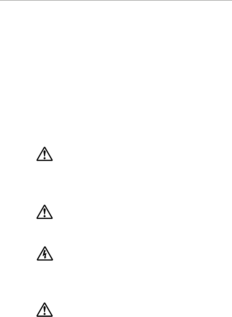
1.1 What will my C-Series integrate with?
When used as part of a SeaTalk system it will display information from other SeaTalk
and NMEA instruments. Information from the C-Series display can be transferred
between applications and to other SeaTalk instruments within the system. For more
detail on system integration, please refer to the Installation Guide.
CANCELOK
RANGE
IN
OUT
PAGE
ACTIVE
WPTS
MOB
MENU
DATA
MENU
CH
OK
16/9 HI/LO
SCAN WATCH
SQ
RAY240
WX
11.18.02
Radar scanner
Navtex receiver
GPS
Remote keyboard
Fishfinder DSM 250
Instruments
Autopilot
AIS receiver
DSC VHF
C-Series display
D9001_1
81221_4.book Page 1 Tuesday, February 28, 2006 5:24 PM
2 C-Series Display Reference Manual
1.2 What can the C-Series Display do?
With the appropriate equipment connected to your system and the necessary data
available, your C-Series display combines the following applications which are used to:
Chart (Chapter 4)
You will need a chart card, and position/heading data, for the chart application to be
fully functional.
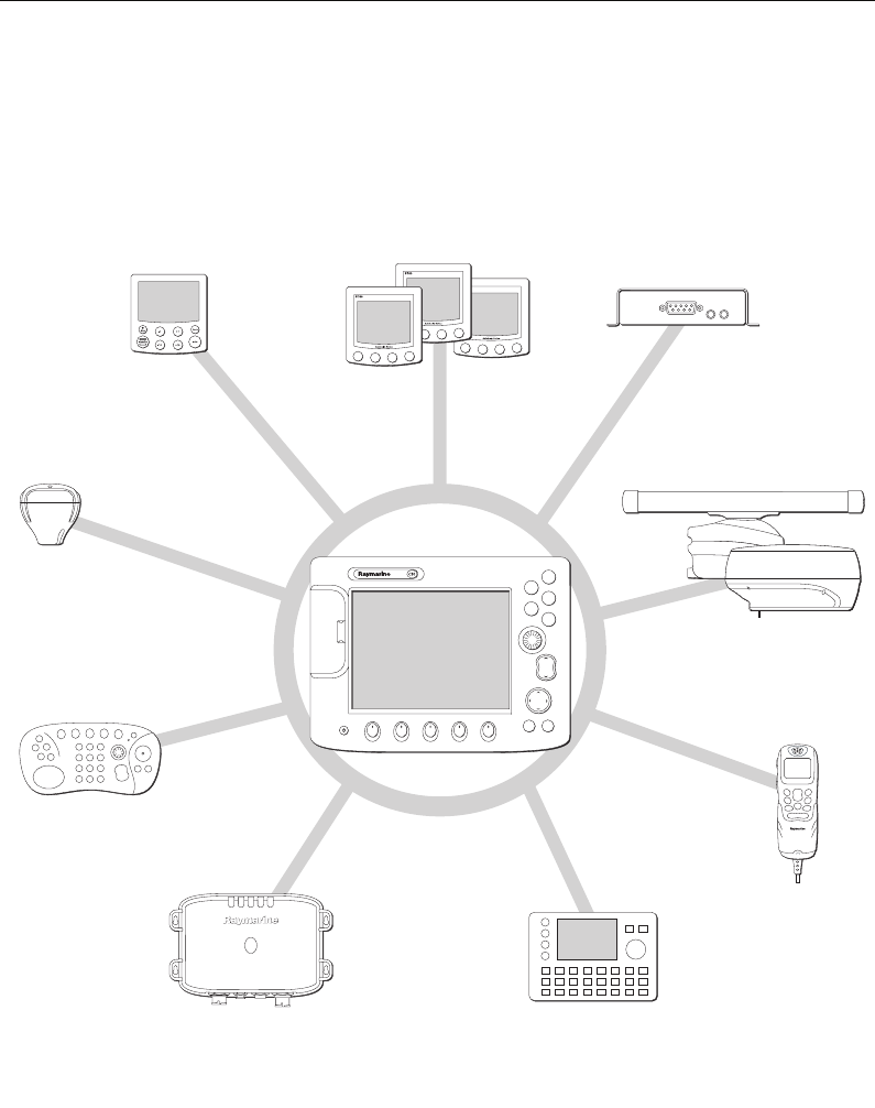
Fishfinder (Chapter 5)
You will need position data, in addition to a DSM250, for your fishfinder to be fully
functional.
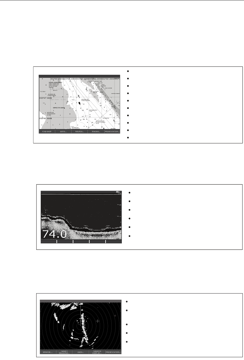
Radar (Chapter 6)
You will need position and heading data, in addition to a compatible scanner, for your
radar application to be fully functional.
0.5nm North-Up (Relative Motion) Local
D7363_2
Locate where you are.
Interpret your surroundings.
Monitor where you are going.
Record where you have been.
Navigate to a specified position (waypoint).
Build and navigate routes.
View details of nearby features & services.
View details of boats equipped with AIS.
Distinguish between fixed and moving objects.
Measure distances and bearings.
D7377-1
Build a picture of what is below your vessel.
Locate & distinguish underwater objects & targets.
Distinguish the seabed and its texture.
Obtain information about water depth, temperature.
Mark a point of interest, fishing spot etc.
Determine depths and distances of targets.
TRANSDUCER
SETTINGS… ZOOM… BOTTOM LOCK… A-SCOPE… PRESENTATION…
200kHz: Auto Range: Auto
Detect landmasses & navigation markers.
Detect and measure the range and distance of other
vessels.
Acquire targets and track them for collision avoidance.
Navigate to a specified position (waypoint).
View details of boats equipped with AIS.
VRM/EBL... GAIN... TARGETS
DISPLAY... PRESENTATION...
TARGET
TRACKING...
6nm North-Up (Relative Motion) Rings 1nm
D7375-2
81221_4.book Page 2 Tuesday, February 28, 2006 5:24 PM
Chapter 1: Overview 3
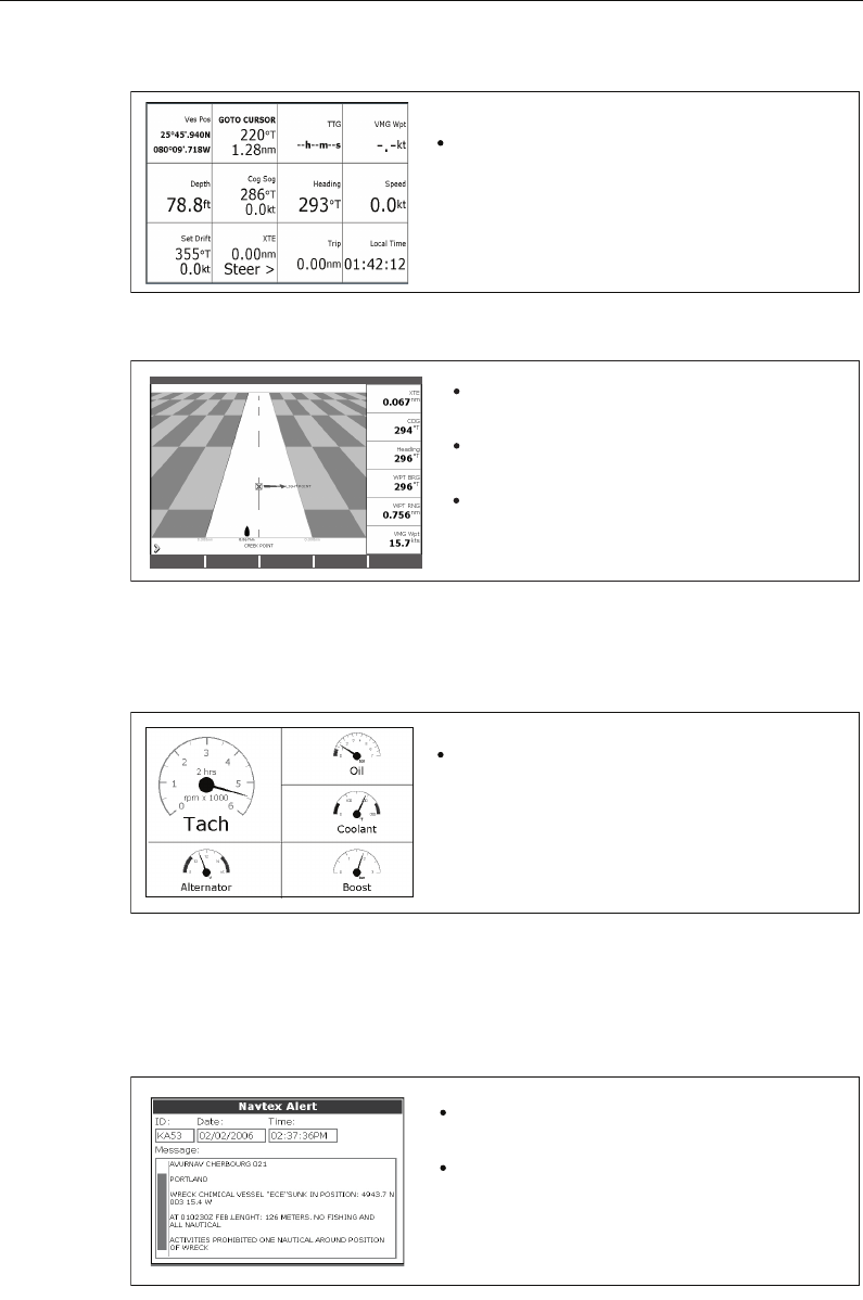
Data (Chapter 7)
Course Deviation Indicator (Chapter 8)
You will need accurate heading and position data for your CDI application to be fully
functional.
Engine Monitor (Chapter 9)
T
Navtex (Chapter 10)
Major areas of NAVTEX coverage include the Mediterranean Sea, the North Sea,
coastal areas around Japan and areas around the North American continent.
You will need a Navtex receiver connected to your system via NMEA, in order to receive
this data.
D7376-1
View data generated by the system or by instruments
available on NMEA 0183, NMEA 2000 and SeaTalk or
SeaTalk2.
D7379-1
View real-time display of your vessel on a 'rolling
road' in 3D perspective.
Give details of any correction required to steer your
vessel along a given course.
View data about the distance and time to go until
you reach a specified point.
3nm North-Up Relative Motion Local
D7497-1
View engine data e.g. engine temperature, oil pressure,
fuel level etc from up to three engines on a compatible
engine system.
D8728-1
Automatic broadcast of localised Maritime Safety
Information (MSI)
Receive navigational and meteorological warnings, and
search and rescue information.
Draft
81221_4.book Page 3 Tuesday, February 28, 2006 5:24 PM

4 C-Series Display Reference Manual
Waypoints (Chapter 3) & AIS (Chapter 11)
Whilst not applications in their own right, waypoints and AIS are handled at system
level and are covered in separate chapters.
1.3 The Simulator
The C-Series Display includes a simulator
mode, which allows you to practice
operating your display without data from a GPS antenna, radar scanner, fishfinder or
AIS receiver. The simulator mode is switched on/off in the System Setup Menu (see
page 183
). Once enabled, you can use the simulator:
•Before installation - Simply connect the display to a 12V DC power supply,
fused at 1 amp by attaching the red core from the power lead to positive (+) and
the black core to negative (-).
•After installation - Whilst in a marina or at anchor.
Please note that system settings made whilst in simulator mode, are not transmitted
via SeaTalk to other equipment.
Important: Incoming AIS safety messages cannot be displayed while the simulator is
switched on.
81221_4.book Page 4 Tuesday, February 28, 2006 5:24 PM

Chapter 2: General Operation 5
Chapter 2: General Operation
2.1 Introduction
This chapter gives details of the general operation of the C-Series display, and covers
the following subjects:
• Powering the display on/off.
• Using the controls.
• Application display.
• Displaying and editing additional information.
• Adjusting the display lighting.
• Initial setup procedures.
• Using CompactFlash cards.
• Managing data.
• Emergencies and warnings.
2.2 Powering the display ON/OFF
Power ON
Press the POWER button until the introductory logo is displayed. The keys
light up and after a few seconds an application page and a navigation
warning is displayed. Read this information and then press OK to remove it.
At this time the radar scanner (if fitted and powered) is checked for compatibility with
the display. An error message is displayed if the scanner is incompatible.
Power OFF
Press and hold the POWER button until the power down count reaches
zero. If the POWER button is released within the countdown period, power
off is cancelled.
Remember to replace the suncover to protect the display.
D6577-1
81221_4.book Page 5 Tuesday, February 28, 2006 5:24 PM
6 C-Series Display Reference Manual
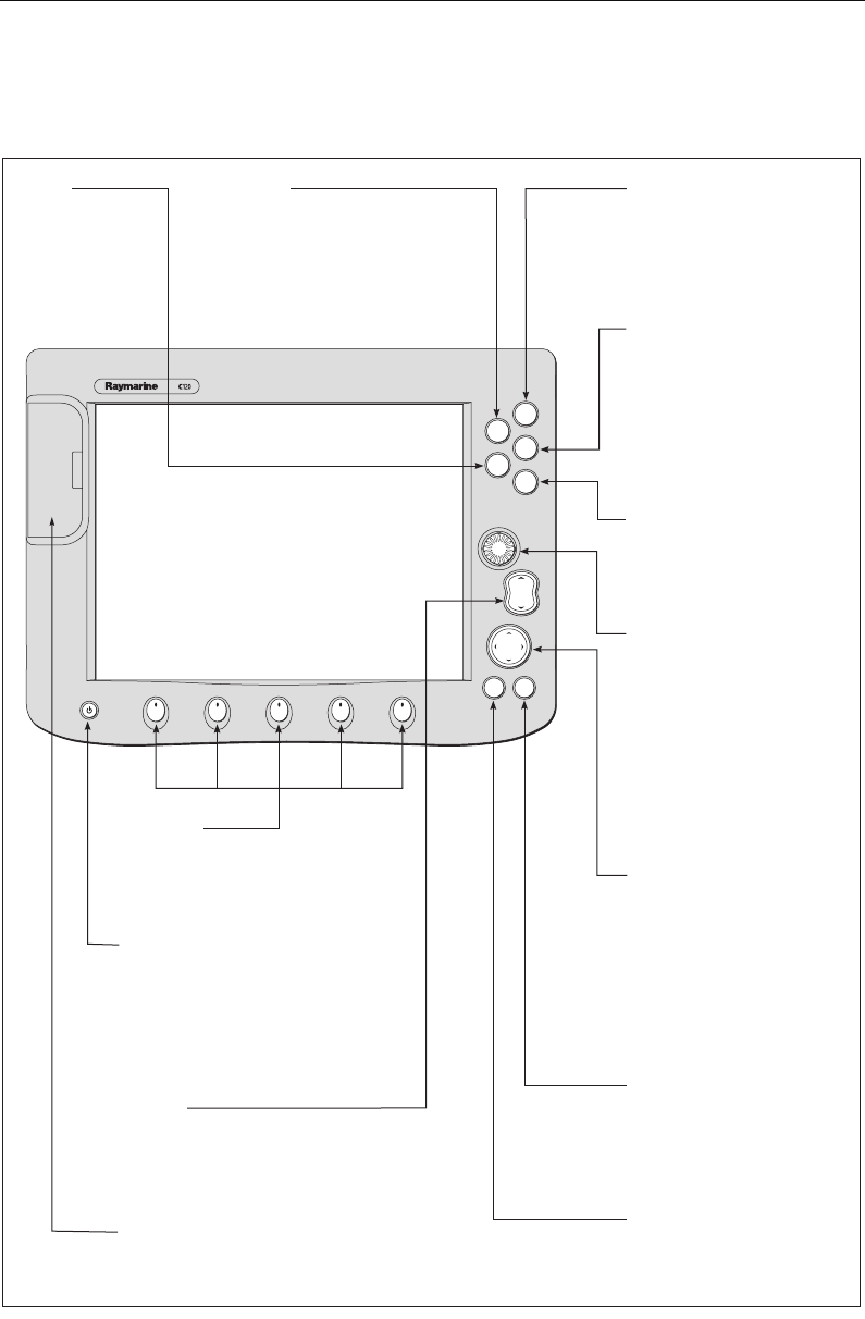
2.3 Using the controls
The control panel
RANGE
CANCELOK
PAGE
ACTIVE
WPTS/
MOB
MENU
DATA
IN
OUT
OK
Press to select an on-screen
option, or return to the
previous soft key set or menu.
DATA
Press to access
ruler, chart vectors,
archive & transfer
and data bar
on/off functions.
Trackpad
Used to control the on-screen
cursor and to scroll through
menu items.
Press the corresponding edge
of the trackpad to move the
cursor horizontally, vertically or
diagonally.
Press and hold to move rapidly
over larger distances.
CANCEL
Press to cancel the selected
on-screen option when editing
data; also used to return to
the previous soft key set or
menu.
MENU
Press to access the set up
menus.
Press and hold to access help
information.
ACTIVE
When multiple windows are open:
- Press to select required window.
- Press and hold to maximise current
window.
- Press again to return to multiple
windows.
PAGE
Press to scroll through available
pages.
Press and hold to select different
page set or customise your own
layout.
WPTS/MOB
Press to display the waypoint
soft keys.
Press again to place waypoint at
your boat's position.
Press and hold to place a
Man Overboard (MOB)
marker at your current position.
Press and hold again to exit
RANGE
Press to change the display
scale so that a smaller or
larger area can be seen on
the screen.
Power
Press once to turn ON.
Press again to access
backlight functions and
scanner controls.
Press and hold to turn the
display OFF.
Chart Card slot
Open the cover to install
CompactFlash cards.
Softkeys
Press to select the corres-
ponding function identified
by the on-screen label
D7517_1
Rotary control
Use to edit alpha-numeric
values, and scroll through lists.
Turn clockwise to increase
value and counter-clockwise to
decrease value.
Press to move the cursor to the
next character when editing
text.
Use to edit symbology (VRM/
EBL etc).
81221_4.book Page 6 Tuesday, February 28, 2006 5:24 PM
Chapter 2: General Operation 7
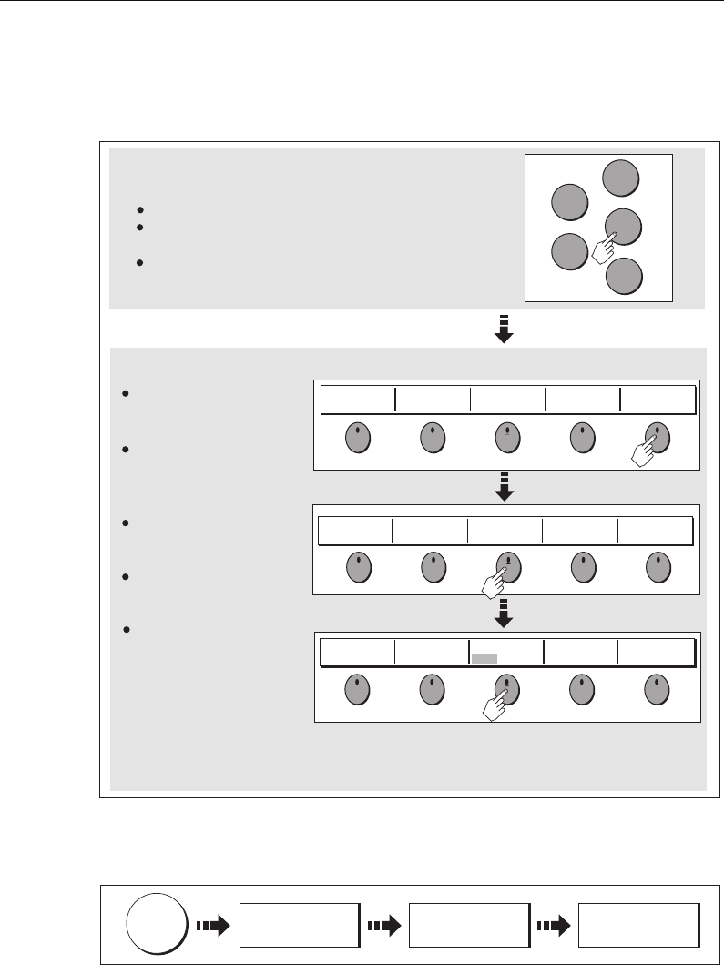
Buttons and soft keys
To navigate to the required function you will need to press a series of buttons and/or
soft keys:
This process of pressing buttons and soft keys to navigate to the required function is
simplified in this manual and represented by a strip e.g.
Note: The key beep that you hear whenever a button or soft key is pressed, can be
switched off and the soft keys automatically hidden if required. For more details,
please refer to the Display Setup Menu on page 191.
WAYPOINT AT
CURSOR
WAYPOINT AT
VESSEL
WAYPOINT AT
LAT/LONG...
GO TO WAYPOINT
OPTIONS…
REVIEW AND EDIT
WAYPOINTS
ERASE WAYPOINT SORT LIST SET DEFAULT SYM
& GROUP...
WAYPOINT
GROUPS...
VIEW AND EDIT
DETAILS…
EDIT DEFAULT
SET UP DEFAULT
SYMB GROUP
D7364-2
WPTS
MOB
PAGE
ACTIVE
MENU
DATA
Example:
The example above shows the series of button and soft key presses
required to change the waypoint default symbol or group.
Access system functions or change what you see on-screen.
Within the text of this document they are written in bold capitals
e.g. WPTS/MOB.
Press and hold to access short cuts.
They change depending on
application or function
being performed.
Press the corresponding key
(below the screen) to select.
Further soft keys may be
displayed.
If a key has several options,
each press will highlight the
next option.
If a key displays a single
value or a slider above, use
the rotary control to adjust.
Within the text of this
document they are written
in capitals e.g. SORT LIST.
Buttons
Soft keys
WPTS
MOB
D7365-2
REVIEW AND EDIT
WAYPOINTS ...
SET DEFAULT SYM
& GROUP...
SET UP DEFAULT
SYMB GROUP
81221_4.book Page 7 Tuesday, February 28, 2006 5:24 PM
8 C-Series Display Reference Manual
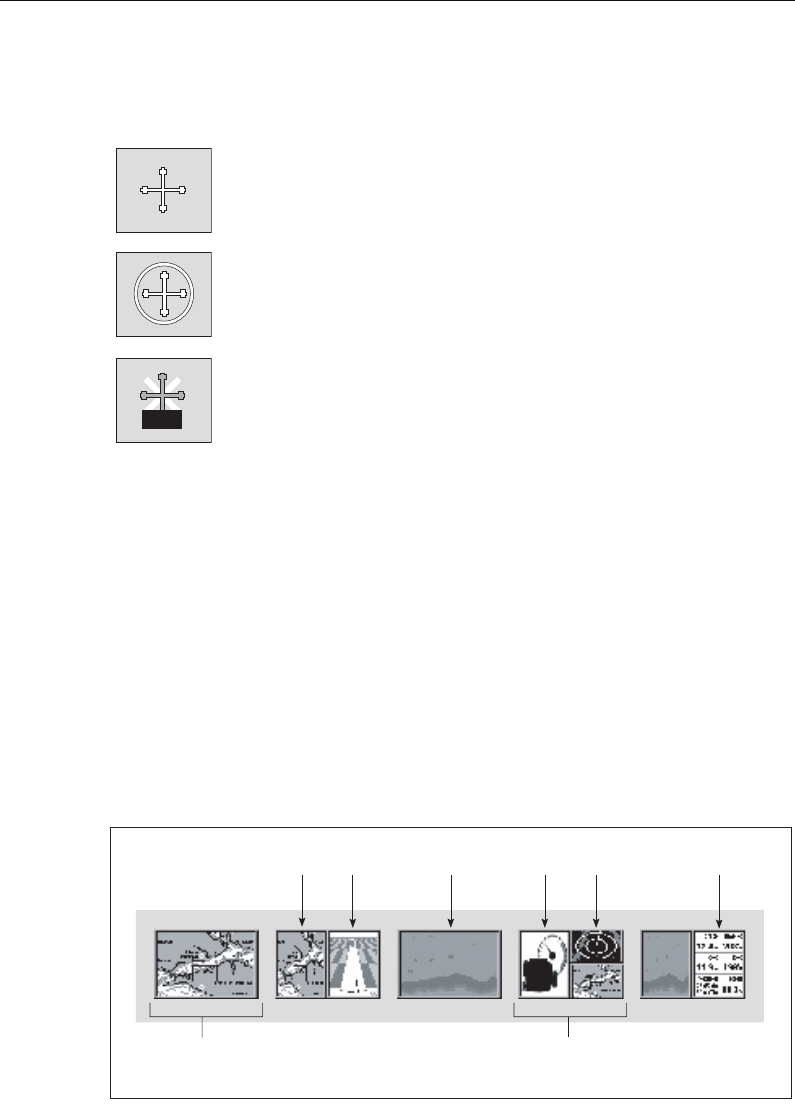
The cursor
When you are using the chart and radar applications, the cursor is used to move
around the screen:
The cursor appears on the screen as a white cross.
If the cursor has not been moved for a short period of time, it changes to
a circle with a cross in it, to make it easier to locate on the screen.
The cursor is context-sensitive - when it is placed over an object e.g. a
waypoint or chart feature, it changes color and a label or information
associated with the object is displayed. When you place the cursor over
certain items, the soft keys change to enable you to access related
operations.
Notes: (1) For a full list of cursor labels and their meanings, please see
page 211
(2) For details of how to temporarily hide the cursor, please see
page 191.
2.4 Displaying applications
The various applications that make up your C-Series system are displayed in a series of
screens known as
page sets
. There are 4 pre-configured and one empty page set to
choose from. Each page set contains 5
pages
. These pages are made up of 1, 2, 3 or 4
windows
combined in various formats. Each window can display an application e.g.
If necessary, you can change the combination and layout of these page sets to meet
your particular needs (see
page 177
).
Note: For details of how to select page sets, pages and windows, please refer to
page 14.
D7366_3
D7368_2
D7369-2
WPT
Page set
Page
(consists of 1, 2,
3 or 4 windows)
Window
D8928_1
CDIChart Radar
Fishfinder
Engine
monitor Data
81221_4.book Page 8 Tuesday, February 28, 2006 5:24 PM

Chapter 2: General Operation 9
2.5 Additional screen information
Information is displayed on the screen using a variety of methods:
* For details of how to adjust and edit the data bar, please see
page 180
Note: To change the size of the text on screen, please see page 191.
3nm Head-Up Relative Motion Rings ½nm
ACKNOWLEDGE
Status icons
Confirm status of DSM,
GPS and scanner.
Status bar
Gives information specific to
each application.
Cannot be edited or moved.
Gives information associated with
your boat or the environment.
Customisable content*
Vertical or horizontal format*
Display or hide*.
Normal or large size*.
Data bar
D7456_1
Contain information you
have added to the display's
memory e.g. waypoints.
Highlight an entry with
trackpad or rotary control to
display related information.
Editable using soft keys.
Dialog boxes
Enable data to be edited or
entered into a store/list
e.g. editing a waypoint.
Alert you to a situation e.g.
alarm, function not available.
Not editable.
May require a response e.g.
press ACKNOWLEDGE to
silence alarms.
Pop-up messages
MARPA ALARM
Target lost (on screen)
Data base lists
Menus (see next page)
Used to configure system
to your particular needs.
3nm Head-Up Relative Motion Rings ½nm
ACKNOWLEDGE
Status icons
Confirm status of DSM,
GPS, AIS and scanner.
Status bar
D7456_2
Status bar
Gives information specific to
each application.
Cannot be edited or moved.
Gives information specific to
each application.
Cannot be edited or moved.
Gives information associated with
your boat or the environment.
Customisable content*
Vertical or horizontal format*
Display or hide*.
Normal or large size*.
Data bar
Contain information you have
added to the display's memory
e.g. waypoints.
Highlight an entry using
trackpad or rotary control to
display related information.
Editable using soft keys.
Dialog boxes
Enable data to be edited or
entered into a store/list e.g.
editing a waypoint.
Alert you to a situation e.g.
alarm, function not available.
Not editable.
May require a response e.g.
press ACKNOWLEDGE to
silence alarms.
Pop-up messages
MARPA ALARM
Target lost (on screen)
Data base lists
Menus (see next page)
Used to configure system to
your particular needs.
81221_4.book Page 9 Tuesday, February 28, 2006 5:24 PM
10 C-Series Display Reference Manual
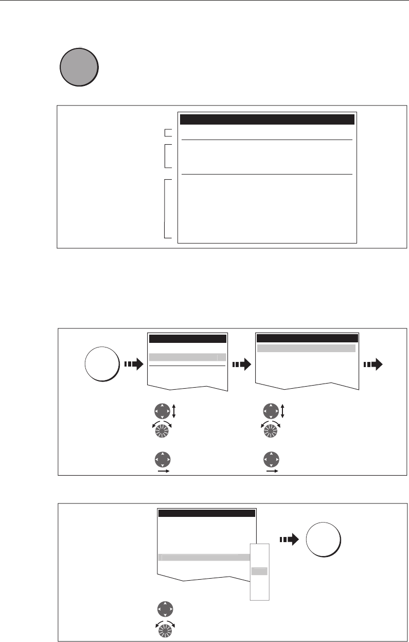
Menus
0
Menus enable you to configure your system to your particular needs.
Whenever the MENU button is pressed, the Setup menu is displayed
containing a list of all the menus available for the active application
together with system wide menus e.g.
For details of application menus, please refer to the appropriate chapter. For all other
settings, please refer to
Chapter 12:System setup and customizing
.
To access a menu:
1. Select the appropriate menu and setting:
2. To change the setting:
D6582-1
MENU
MENU
D7370_2
Menus for the active
application
External equipment/
instruments
System-wide menus
Setup
Radar Setup ...
GPS Status...
Compass Setup...
AIS Layer Status...
System Setup...
Alarm Setup...
Display Setup...
Databar Set...
Select Page Setup...
System Diagnostics...
Remove CF Card
D8500_1
Setup
Chart Setup...
GPS Status...
Compass Setup...
C
artography Setup..
.
MENU
Cartography Setup Menu
Chart Display Detailed
Chart Grid On
Chart Text On
Chart Boundaries ON
Spot Soundings ON
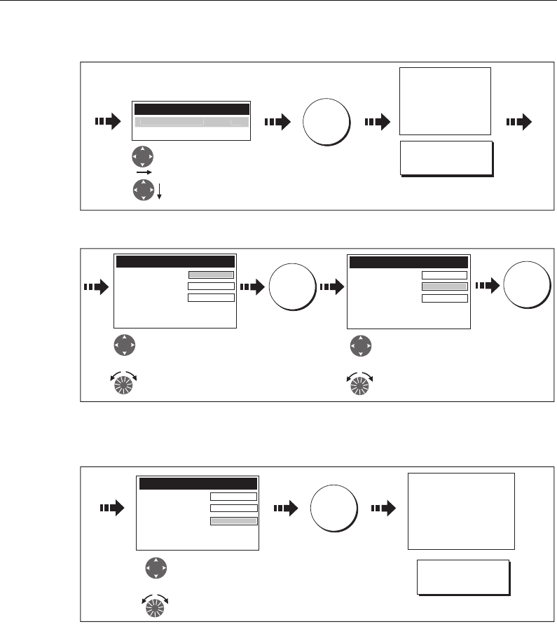
1. Highlight item, using:
Rotary control
2. Select item, using:
Trackpad (right)
Trackpad (up/down)
or
1. Highlight item, using:
Rotary control
2. Select item, using:
Trackpad (right)
Trackpad (up/down)
or
D8501_1
Cartography Setup Menu
Chart Display Detailed
Chart Grid On
Chart Text On
Chart Boundary ON
S
pot Soundings O
N
Depth Contour ALL
Nav. Marks ON
Highlight or change value to
new setting, using:
S
a
f
et
y
Contour 66
ft
OFF
7ft
10ft
20ft
33ft
66ft
16f
t
OK
Trackpad (up/down)
or
Rotary control
81221_4.book Page 10 Tuesday, February 28, 2006 5:24 PM
Chapter 2: General Operation 11
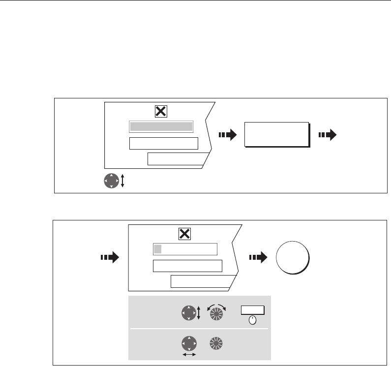
Editing the dialog box information
Dialog boxes enable data to be edited or entered into a list e.g. Edit Waypoint screen.
To edit/enter data into a dialog box:
1. Select the field for editing:
2. Edit/enter data and save:
3. Repeat Steps 1 and 2 if necessary.
Notes: (1) Character text can be entered in upper or lower case. (although the
system is not case sensitive e.g. WAYPOINT 1, Waypoint 1are con-
sidered to be the same name).
(2) If you need to use special or accented characters (e.g. ~ ` ´), the
Extended Character Set should be switched to ON in the System
Setup Menu (see page 183).
D8502-1
Highlight field to be edited
e.g. waypoint name
My Waypoints
Name
Symbol
Group
Comment
Wa
yp
oint
1
EDIT NAME
e.g.
D8503-1
OK
ayp
oint
1
My Waypoints
Name
Symbol
Group
Comment
W
a
To change
character or
selection, use:
e.g.
,
or
To move to next
character for
editing, use:
or
Press
Turn
81221_4.book Page 11 Tuesday, February 28, 2006 5:24 PM
12 C-Series Display Reference Manual
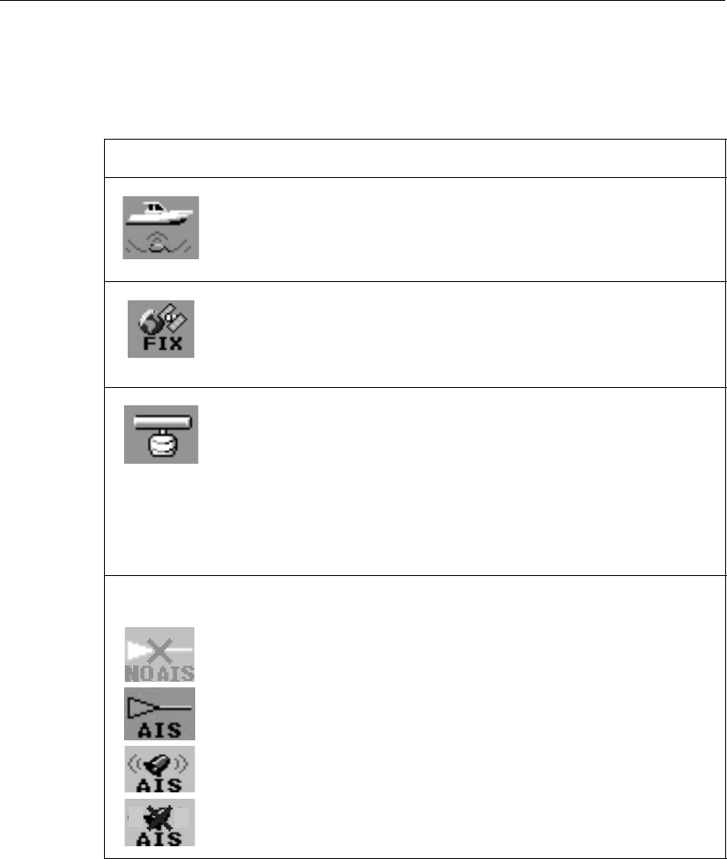
Status icons
The status icons on the data bar confirm whether the appropriate connections to your
C-Series system have been made:
Note: These icons will also appear when you are in simulator mode.
Status icon Description
The boat and fish icon indicates the current status of your fishfinder:
Icon animated - connection to a DSM has been successful.
Icon static - the DSM is connected but not transmitting.
Icon greyed-out - no DSM is connected.
The satellite icon indicates the current status of your GPS:
FIX - your unit is successfully connected to a GPS receiver.
NO FIX - your unit has been unable to connect to a suitable GPS receiver.
The scanner icon indicates the current status of your radar scanner:
Icon rotates - the scanner is transmitting (TRANSMIT/TX mode).
Icon static - the scanner is powered on but is not currently transmitting
(STANDBY mode).
Icon greyed out - this indicates that the scanner is currently powered
off (OFF mode).
Icon rotates and is then static - a power save mode in which the
scanner powers on/off intermittently (TIMED TRANSMIT mode).
o
The AIS icon indicates the current status of the AIS function:
AIS unit not available i.e. not connected or off.
AIS unit is switched on and operating.
AIS unit on with active alarms.
AIS unit switched on and operating but dangerous and lost alarm dis-
abled.
D6892-3
(animated icon)
D6893-2
(static icon)
D6894-2
(static icon)
D8929_1
81221_4.book Page 12 Tuesday, February 28, 2006 5:24 PM
Chapter 2: General Operation 13
2.6 Initial setup procedures
When you first use your C-Series Display after it has been commissioned (see
Installation Guide), we recommend that you carry out the following:
• Set the language, the date and time format and preferred units of measurement.
• Select a page set.
• Select an application page/window.
• Adjust the display lighting.
Note: For full details of all setup and customizing options, please refer to Chapter
12:System setup and customizing.
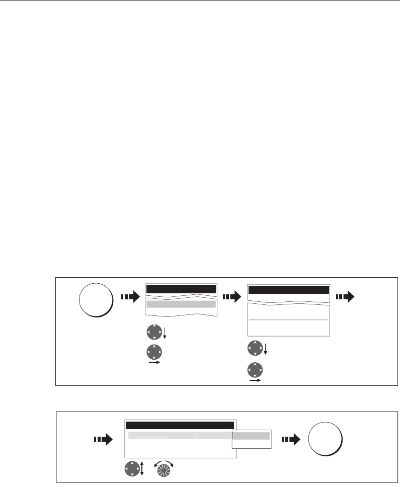
Setting the language, date/time format and units of mea-
surement
To adjust the language, date/time format and units of measurement to your preferred
settings:
1. Select the setting:
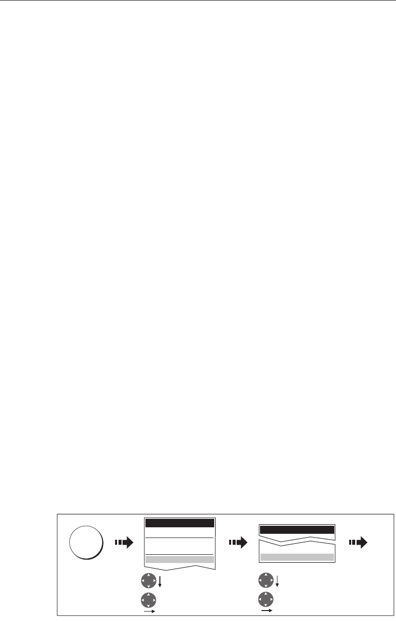
2. Adjust the setting:
3. Repeat this process until you have changed all of these settings.
Note: For full details of all System Setup options, please refer to Chapter 12:System set-
up and customizing. For application specific set up options, please refer to the appro-
priate chapter.
Setup
System Setup...
Alarm Setup...
System Setup Menu
Date/Time Setup...
Units Setup...
System Integration Setup...
Waypoint Password Setup...
Position Made Lat/Lon...
D8504-1
Highlight
System Setup
Enter System
Setup
Highlight required
setting
Enter setting
MENU
D8505-1
Change value as
required
OK
or
Time Format 12hr
Local Time Offset UTC
Date/Time Setup Menu
dd/mm/yy
m
m
/dd/
y
y
D
ate
F
ormat mm
/dd/
y
y
e.g.
81221_4.book Page 13 Tuesday, February 28, 2006 5:24 PM
14 C-Series Display Reference Manual
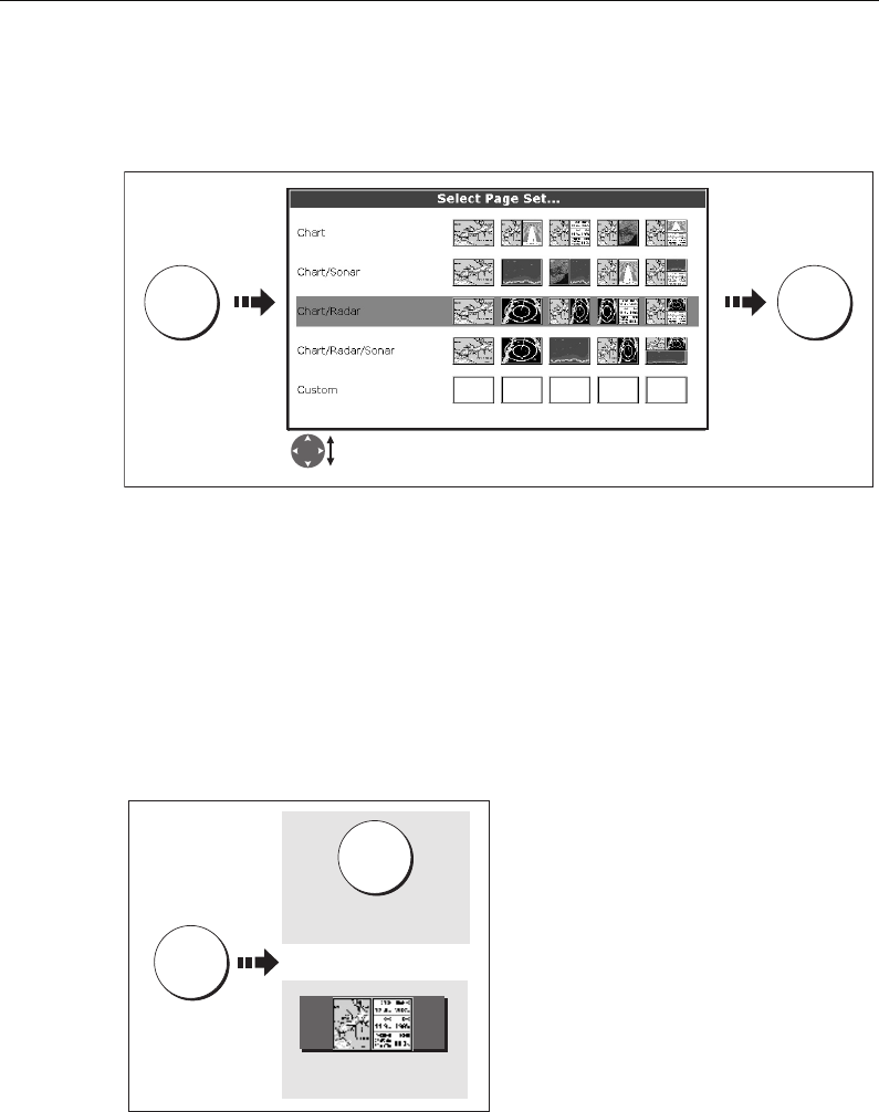
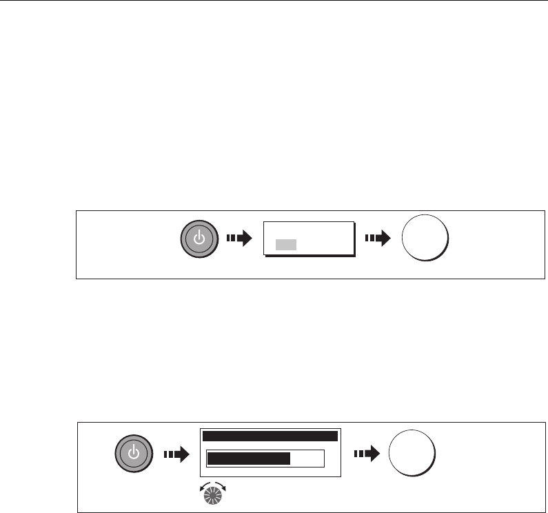
Selecting a page set
Your Display has four pre-configured page sets and one empty set for you to choose
from.
Note: Alternatively, you can access the Select Page Set screen via MENU.
If none of the pre-configured page sets meet your particular requirements and/or you
intend to use the engine monitor application, refer to the Setup and Customizing
chapter for details of how to customize both the layout and the application appearing
in each window.
Selecting an application page
Once you have selected the appropriate page set (see previous section), choose the
application page that you wish to use:
D8511-1
Press &
hold
Highlight appropriate pre-configured page set
PAGE OK
D8512-1
Press until required
page displayed
Or:
Press soft key of
required page
PAGE
PAGE
81221_4.book Page 14 Tuesday, February 28, 2006 5:24 PM
Chapter 2: General Operation 15
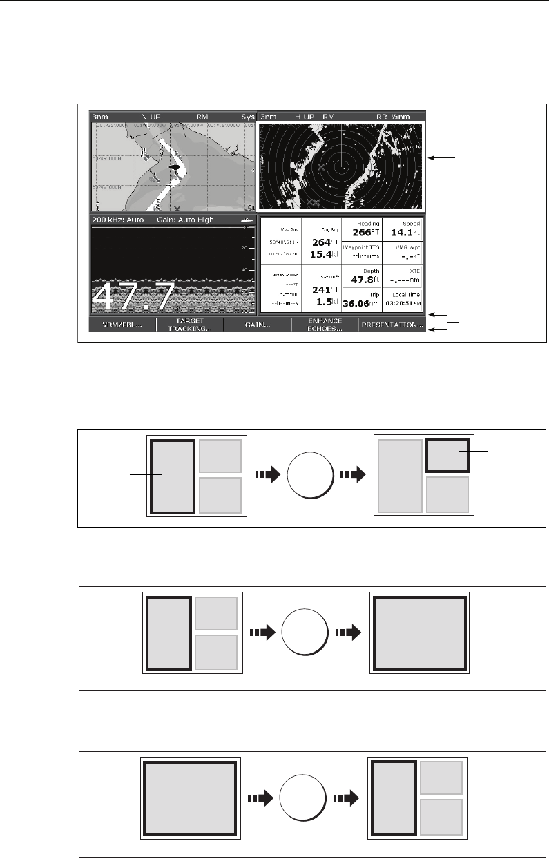
Selecting an application window
When the selected page has more than one window, the window that is currently
active will be bordered in red e.g.
Changing the active window
To change the active highlight to other windows on the page and display the
associated soft keys:
Multiple to single window
To make the active window full-screen when multiple windows are being displayed:
Single to multiple windows
To return to multiple windows:
Active window
highlighted
Soft keys
associated with
active window
D8516_1
D8513-1
Press to move
active window
e.g.
ACTIVE
Active
window
Active
window
D8514-1
Press and
hold
ACTIVE
Multiple windows Single window
D8515_1
ACTIVE
Multiple windowsSingle window
81221_4.book Page 15 Tuesday, February 28, 2006 5:24 PM
16 C-Series Display Reference Manual
Adjusting the display lighting
The display has two distinct color palettes, for day and night operation. You can also
manually adjust the backlight level.
Note: The display lighting is a local setting and will therefore only affect the individual
display on which you are working.
Day/night operation
To select the day/night mode of operation:
The display saves the current palette when the unit is powered off. If the palette was set
to NIGHT when it was last used, and you then power on in bright sunlight, it may be
difficult to see the screen. Reset the palette to DAY to return to normal daytime
lighting.
Backlight level
To adjust the backlight level when in day or night operation mode:
D6802-3
Toggle as required
OK
PALETTE
DAY NIGHT
D8517_1
Backlight Level
Change the level as required
OK
81221_4.book Page 16 Tuesday, February 28, 2006 5:24 PM

Chapter 2: General Operation 17
2.7 Using CompactFlash cards
Cautions
CAUTION: CompactFlash Card Installation
When installing CompactFlash cards ensure that the card is fitted the correct
way around. DO NOT try to force the card into position as this may result in
irreparable damage to the card.
CAUTION: Water Ingress
To prevent the ingress of water and consequent damage to the display,
ensure that the chart card door is firmly closed at all times. This can be
confirmed by an audible click.
CAUTION: Card Removal
DO NOT use a metallic instrument such as a screwdriver or pliers to help you
remove a card, as doing this can cause irreparable damage.
CAUTION: Card writing
CompactFlash cards can be damaged if they are removed from the unit
during either a read or write operation. A warning is displayed during write
operations. The unit is continually reading the card. It is therefore essential
that before removing the card you follow the correct procedure to stop
access to the card.
What are CompactFlash cards used for?
CompactFlash cards enable you to get the most from your display. Their uses include:
•Detailed cartographic information
Obtain detailed cartographic information of the area that you navigate using Nav-
ionics® chart cards. To check the current availability of Navionics chart card types,
please visit www.navionics.com or www.navionics.it.
The amount of cartographic detail shown varies for different areas and for differ-
ent scales. The chart scale in use is indicated in the status bar - the number repre-
sents the distance in nautical miles from the top of the chart window to the
bottom of the chart window.
•Archiving
To archive waypoints, routes and tracks.
•Saving
To save waypoint, route and track data for use by other equipment e.g. a PC.
You can remove and insert cards while a chart is displayed provided that you follow the
correct procedure (see
page 18
). The chart information is retained on-screen until the
chartplotter redraws the screen; for example, when you pan outside the current area,
or use the RANGE button to change the chart scale.
81221_4.book Page 17 Tuesday, February 28, 2006 5:24 PM
18 C-Series Display Reference Manual
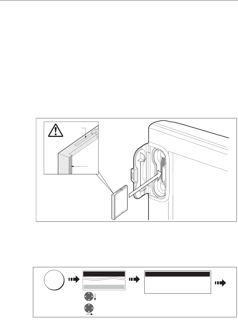
Inserting a card
To insert a card, refer to the illustration and:
1. Check that you are using the correct type of card (see
Important Information
, at the
beginning of this manual
).
2. Open the chart card door, located on the front left of the display.
3. Insert the card as shown, with the lip of the card facing inwards. It should position
easily. If it does not, DO NOT force it, check the direction in which the lip is facing.
4. Gently press the card home.
5. To prevent the ingress of water and consequent damage, close the chart card door
and press firmly until a click is heard.
Removing a card
...with the unit powered on
1. Select the CF Card Removal function:
IMPORTANT:
If you try to remove a card without accessing the setup menu, a blue screen and
warning message is displayed and the unit must be restarted.
You must only remove the card while the CF Card Removal message is displayed.
Once the message is closed, the card should no longer be removed.
2. Open the chart card door.
D7215_2
Narrow
Groove
Lip
Setup
System Diagnostics...
Remove CF Card
D8518-1
Highlight
Remove CF Card
Select Remove
CF Card
MENU
CF Card Removal
You may now safely remove your
compact flash card.
Press OK or CANCEL when finished.
81221_4.book Page 18 Tuesday, February 28, 2006 5:24 PM

Chapter 2: General Operation 19
3. Grip the card and pull to remove it from its slot.
4. To prevent the ingress of water and consequent damage, close the chart card door
and press firmly until a click is heard.
5. Press OK.
...with the unit powered down
1. Open the chart card door.
2. Grip the card and pull to remove it from its slot.
3. To prevent the ingress of water and consequent damage, close the chart card door
and press firmly until a click is heard.
2.8 Managing data
This section explains how you can manage the data contained in your C-Series and
includes the following:
• Writing/retrieving to a CF card.
• Erasing information from a card.
• Erasing information from your system.
• Transferring information to/from a PC.
• Password protection.
Writing/retrieving data to a CompactFlash card
Your display can save up to 1,000 waypoints, 100 routes and 10 tracks in data base
lists. Once this number is reached you will need to archive data to a CompactFlash card
for safe-keeping or retrieval at a later date. Alternatively, you can transfer data to
another instrument or PC using NMEA. When navigation is active, you can also receive
waypoints, routes and tracks from a PC, SeaTalk and NMEA instruments (see
page 22
).
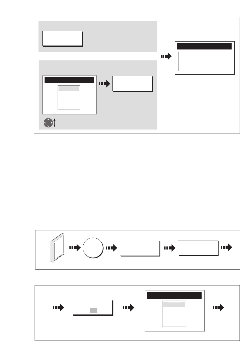
Saving information to a card
Important:
Raymarine strongly recommend that you save data to a separate CompactFlash card
and not to a Navionics card containing cartography.
1. Insert card and select the SAVE TO CARD function:
ARCHIVE AND
TRANSFER SAVE TO CARD
DATA
D8070_1
Insert card
81221_4.book Page 19 Tuesday, February 28, 2006 5:24 PM
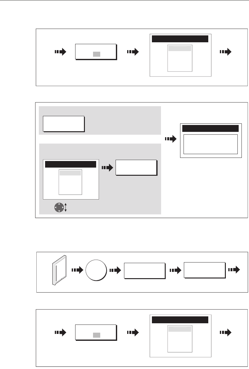
20 C-Series Display Reference Manual
2. Select list containing data for saving:
3. Define data for saving
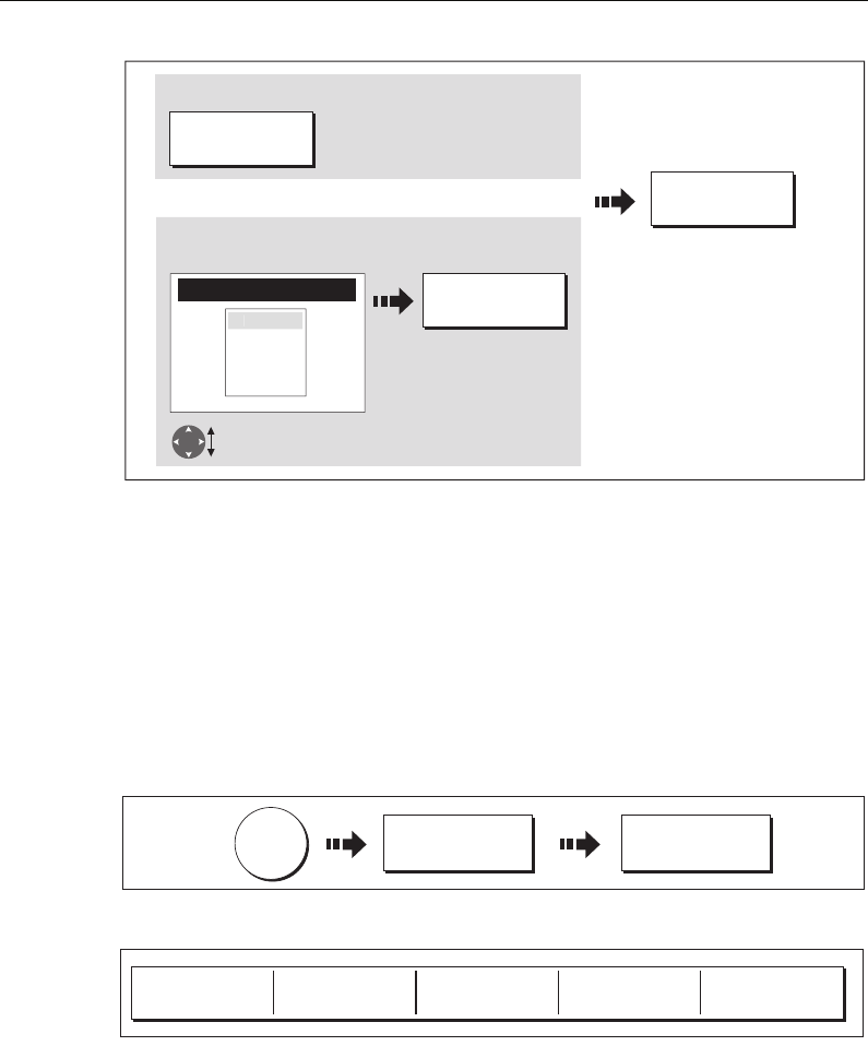
Retrieving information from a card
1. Insert card and select the RETRIEVE FROM CARD function:
2. Select required list:
3. Define data to be retrieved:
Toggle to required
list
D8655_1
Contents for selected list displayed
SELECT LIST
WPT RTE TRK
ROUTE LIST
Route 2
Route 3
R
oute
1
e.g.
D8520_1
Follow on-screen instructions
to remove card
Save Route
SAVE ALL
SAVE ROUTE
Or
To save all items in list to card:
To save individual items:
Highlight item
for saving
e.g.
e.g.
ROUTE LIST
Route 2
Route 3
R
oute 1
ARCHIVE AND
TRANSFER
RETRIEVE FROM
CARD
DATA
D9094_1
Insert card
Toggle to required
list
D8655_1
Contents for selected list displayed
SELECT LIST
WPT RTE TRK
ROUTE LIST
Route 2
Route 3
R
oute
1
e.g.
81221_4.book Page 20 Tuesday, February 28, 2006 5:24 PM
Chapter 2: General Operation 21
If whilst retrieving information a selection is already found to exist on the system, a
warning message will appear. The soft keys will change to give you the options of
retrieving as new, replacing or cancelling the retrieving process
Erasing information from a card
If you wish to remove information from a card, for example you no longer need it, or
the card is full, it can be erased by using the ERASE FROM CARD soft keys. A message
will be displayed on screen asking you to confirm that you want to delete the item(s),
before it takes place.
1. Insert the card and select the ERASE FROM CARD function:
2. Select the required list:
3. Define data to be deleted:
D8656_1
Follow on-screen instructions
Retrieve Route
RETRIEVE ROUTE
Or
To retrieve all selected database items:
To retrieve individual items:
Highlight item for
retrieving
e.g.
RETRIEVE ALL
ROUTE LIST
Route 2
Route 3
Route
1
ARCHIVE AND
TRANSFER
ERASE FROM
CARD
DATA
D8168_1
Insert card
Toggle to required
list
D8655_1
Contents for selected list displayed
SELECT LIST
WPT RTE TRK
ROUTE LIST
Route 2
Route 3
R
oute
1
e.g.
81221_4.book Page 21 Tuesday, February 28, 2006 5:24 PM
22 C-Series Display Reference Manual
Sending and receiving information using a PC
You can transfer and retrieve waypoints or routes to and from another instrument or
PC using NMEA.
With a RayTech 6.0’s planner you can transfer waypoints and routes via a CF memory
card. Such transfers require that the PC be connected to the display’s NMEA port via a
serial data cable.
To transfer or receive information:
1. Select the transfer on NMEA option:
2. Press the appropriate soft key to send or receive NMEA:
Note: If you wish to stop the transfer at any point, press
STOP TRANSFER.
3. When transfer is complete, STOP TRANSFER greys out and the soft keys reappear.
D8657_1
YES
ERASE ALL
ERASE ROUTE
Or
To delete all items:
To delete individual items:
Highlight item for
deleting
e.g.
ROUTE LIST
Route 2
Route 3
Route
1
DATA
ARCHIVE AND
TRANSFER
TRANSFER ON
NMEA...
D8638_1
SEND WPTS ON
NMEA
SEND RTES ON
NMEA RECEIVE ON NMEA
D6808-2
STOP TRANSFER
81221_4.book Page 22 Tuesday, February 28, 2006 5:24 PM
Chapter 2: General Operation 23
Password protecting your waypoints
If required, you can prevent access to, modification and sight of your waypoint and
route databases and functions by means of a password.
Password confirmation
When Password Protection is enabled and you are attempting to access a password
protected function for the first time during a power-cycle, the system will request
confirmation of your password before you can:
• Access WPTS key functions. This does not affect the operation of the MOB function.
• Access ROUTES soft key functions.
• Create a route from a track. All other track functions are unaffected.
• Archive or transfer any waypoints.
• Enter the Waypoint Password Setup menu.
Note:
Once you have provided a password to the system, it must be entered to access
the Password Setup sub-menu, regardless of the whether Password Protection is set to
ON or OFF.
Disabled data/functions
When Password Protection is ON and you have not entered a password you will be
unable to:
• View details of waypoint and route databases.
• Edit waypoints or routes.
• Goto an existing waypoint.
• Follow a route.
• View waypoints on screen (even when the SHOW/HIDE status is set to SHOW).
• View waypoint names on screen (even when WAYPOINT NAME is set to ON).
All other options including GOTO CURSOR are unaffected.
Setting up a password
To setup a password:
1. Select Waypoint Password Setup:
MENU
D8954_1
Highlight required
System Setup Menu
Select System Setup
Menu
Highlight Waypoint
Password Setup
Select Waypoint
Password Setup
System Setup Menu
System Integration
Waypoint Password Setup
Setup
Radar Setup...
GPS Status...
Compass Setup...
System Setup...
81221_4.book Page 23 Tuesday, February 28, 2006 5:24 PM
24 C-Series Display Reference Manual
2. Change the Enable Password status to ON, read and accept the warning:
3. Enter a password and confirm it:
Note:
The password is case sensitive.
4. Add a hint, to help you to remember your password (optional):
The password is now set and protection enabled although access to the waypoint and
route functions remains available until you restart your system.
Note:
If required, this password can be changed by selecting the Change Password
option on the Waypoint Password Setup Menu.
Enabling/disabling password protection
Once you have set up a password on your system (see previous section) you will need
to key in this password whenever you want to change the status of the password
protection feature.
To enable/disable password protection:
1. Select Waypoint Password Setup:
OK
D8962_1
Select ON.
Select Enable
Password
Waypoint Password Setup
Change Password...
Ena
bl
e Passwor
d
O
N
Read and accept
the warning
Setting Password Protection
required a password to access
your waypoint and route
databases.
If you forget your password you
will lose your waypoints and
routes
Raymarine recommends that you
archive your waypoints and
routes
YES
D8957_1
Enter a password
(1-16 characters)
and/or:
Edit Password
Password:
Confirm Password:
Hint:
Choose a word that will help you
to remember your password
Repeat to confirm
the password
and/or:
OK
Carrot
Edit Password
Password:
Confirm Password:
Hint:
Choose a word that will help you
to remember your password
Carrot
Carrot
e.g. e.g.
OK
D8958_1
Add a hint word
(0-16 characters)
Read and accept the warning
and/or:
Edit Password
Password:
Confirm Password:
Hint:
Choose a word that will help you
to remember your password
OK
Carrot
Carrot
Rabbit
e.g.
YES
Your password has been accepted.
If you continue your waypoints
and routes will be protected.
If you forget your password you
will lose your waypoints and
routes
Raymarine recommends that you
archive your waypoints and routes
Do you want to continue?
81221_4.book Page 24 Tuesday, February 28, 2006 5:24 PM
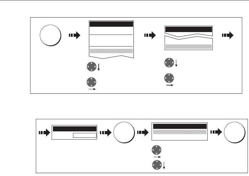
Chapter 2: General Operation 25
2. Enter your password ensuring that the appropriate upper or lower case characters
are used and then enable/disable the password protection, as required.
Important: If you enter an invalid password more than twice within one power cycle
the system shall display the hint. There is no limit to the number of attempts to enter a
valid password but if you forget your password, you will need to perform a Settings
and Data Reset (see
page 184
) which will erase all waypoints in the unit’s memory.
Raymarine strongly recommend therefore that you regularly back-up your waypoints,
routes and tracks to a CF memory card.
MENU
D8960_1
Setup
Highlight required
System Setup Menu
Select Waypoint
Password Setup.
Select System Setup
Menu
Highlight Waypoint
Password Setup
System Setup Menu
System Integration
Waypoint Password Setup
Radar Setup...
GPS Status...
Compass Setup...
System Setup...
OK OK
D8961_1
Select OFF
Select Enable Password
Enter password
Waypoint Password Setup
Change Password...
Enable Password OF
F
Enter Password
Password: Carrot
81221_4.book Page 25 Tuesday, February 28, 2006 5:24 PM
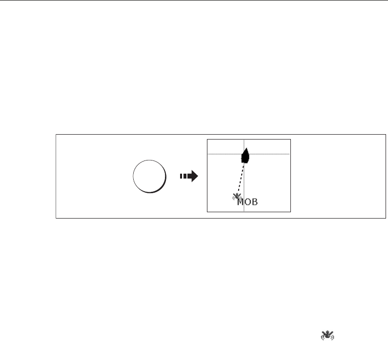
26 C-Series Display Reference Manual
2.9 Emergencies and warnings
You can use your C-Series display to mark the position of a man overboard or to sound
an alarm when a particular situation occurs e.g when a depth limit is reached, a
specified period of time has elapsed etc.
Man Overboard (MOB)
Marking a MOB
If you lose a person or object overboard, and need to return to the location, you should
use the Man Overboard (MOB) function immediately. The MOB function can be
used whilst any application is in use and is activated by either pressing and holding the
WPTS/MOB key for three seconds, or by a MOB message being received from other
equipment on the SeaTalk system.
When a MOB is activated the following is initiated automatically:
•Alarm - the MOB alarm is triggered (Morse --- every 30 seconds).
•Waypoint - a MOB waypoint is placed at your current position.
•Positional information - the bearing, range and vessel position are displayed in
the data bar. These are calculated according to the MOB data type set in the System
SetUp (see
page 183
). Assuming that your boat and the MOB are subject to the
same tide and wind effects, dead reckoning normally gives a more accurate course.
•Radar range change - if radar is transmitting, the system changes the radar
range to 1/8 nm.
•Active navigation is suspended - Navigation to any active waypoint is sus-
pended and any existing navigation function is cancelled. No further GOTO or route
functions are selectable whilst the MOB function is active.
•Autorange motion mode - If radar/chart synchronization is set to OFF (see
page 76
), the chart application changes the motion mode to Autorange.This dis-
plays the largest possible scale of chart that will include both the target waypoint
(MOB symbol) and your on-screen vessel.
•Other equipment - other Raymarine equipment acknowledges the MOB.
• Current position to MOB position - as your vessel moves away from the MOB
position, a dotted line is displayed from your current position to the MOB position.
Note: To obtain a MOB position, you need either position data from a GPS (or equiva-
lent device) or heading and speed data.
WPTS
MOB
D6652-3
Press and hold
until alarm sounds
D9101_1
81221_4.book Page 26 Tuesday, February 28, 2006 5:24 PM
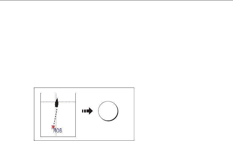
Chapter 2: General Operation 27
Silencing a MOB
To temporarily silence the alarm from a MOB, press any key on any instrument on the
SeaTalk system. After approximately 10 seconds the alarm will sound once more if the
state of MOB is still active.
Silencing an alarm will not deactivate or clear the MOB state.
Clearing a MOB
To clear a MOB and its data:
Once cleared, your chart and radar
applications will return to the motion
mode that applied prior to the MOB
alarm and the GOTO and route functions
will once more be available.
Note: Alternately if you have a MOB key-
pad fitted, press and hold the MOB key.
Alarms
You get warning of a hazard or a particular situation via in-built alarms which are
generated for the system as a whole or for individual applications. When an alarm
sounds, a message box is displayed explaining the cause of the alarm.
You can specify what alarms will operate and the parameters within which they will
sound, via the Alarm Setup Menu (see
page 187
).
Cancelling alarms
Display alarms
By pressing the ACKNOWLEDGE soft key, the alarm is silenced and any message box is
cleared. If the alarm has been generated by the chartplotter, the appropriate action is
taken. For example, following an arrival alarm, the next route leg is activated.
Please note:
• Although you can change the configuration of the arrival alarm, it cannot be turned
off.
• To cancel a MOB alarm, press and hold the WPTS/MOB until the MOB symbol dis-
appears from the screen.
• If an anchor alarm is silenced, but the alarm condition persists, the alarm is
repeated every 30 seconds
External alarms
If an instrument that is connected to the display on SeaTalk generates alarms, these
will sound on your C-Series display accompanied by a pop-up message box. You can
cancel these alarms by pressing the ACKNOWLEDGE soft key. The alarm will be
silenced, but no other action will be taken by the C-Series display.
WPTS
MOB
D8231_1
Press and hold
for 4 seconds
81221_4.book Page 27 Tuesday, February 28, 2006 5:24 PM

28 C-Series Display Reference Manual
81221_4.book Page 28 Tuesday, February 28, 2006 5:24 PM
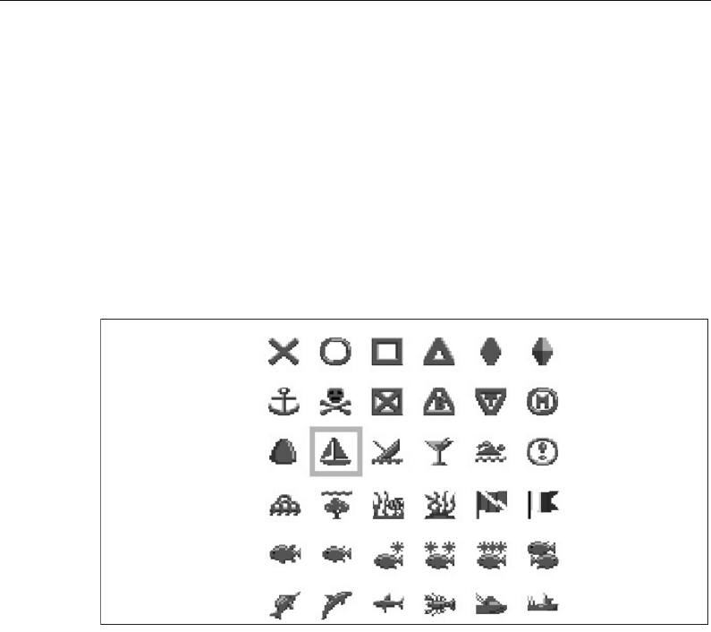
Chapter 3: Working with Waypoints 29
Chapter 3: Working with Waypoints
This chapter gives details of how to place, edit, manage and navigate to a waypoint.
3.1 What is a waypoint?
A waypoint is a position marked on a chart, radar or fishfinder window to indicate a
site (for fishing, diving etc.) or as a place to navigate to. By default, all waypoints are
indicated on screen by a waypoint symbol - x. This symbol can however be changed if
you wish. You can also select an alternative symbol to be used as the default for newly
created waypoints.
Note:
For details of how to change the symbol, please refer to page 35.
Waypoints are a core feature of the C-Series display. They can be created in any
application and are displayed on the radar, chart and fishfinder windows. A series of
waypoints can be combined together to form a route.
The details of all waypoints, irrespective of the application they were created in, are
stored in a dedicated waypoint list which will hold up to 1000 waypoints. All waypoints
are by default, placed in the MY WAYPOINTS group. If required, you can create new
groups and change the default group. If necessary, waypoints can be archived to a
CompactFlash card or transferred to another NMEA compatible instrument. If the
system receives an active waypoint over SeaTalk or NMEA, it is displayed but cannot be
edited.
If required, you can prevent access to, modification and sight of your waypoint and
route databases and functions by means of a password. For more information see
page 23
.
Waypoint symbols
D8696_1
81221_4.book Page 29 Tuesday, February 28, 2006 5:24 PM
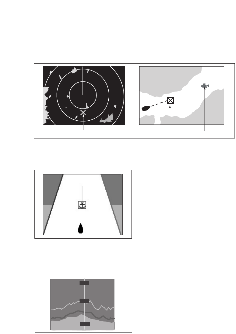
30 C-Series Display Reference Manual
3.2 How are waypoints represented?
Waypoints on Chart and Radar windows
On chart and radar windows, a waypoint is represented when it is both active
(displayed in a box) and inactive (no box) i.e.
Waypoints on CDI windows
On CDI windows, a waypoint is represented only when it is active (displayed in a box).
Waypoints on Fishfinder windows
When a waypoint is created it is represented on fishfinder windows, by a vertical line
labelled WPT. This symbology cannot be changed.
Active waypoint
Waypoint 1
Default waypoint Alternative symbol
D8694_1
D8930_1
D8697_1
WPT
WPT
WPT
81221_4.book Page 30 Tuesday, February 28, 2006 5:24 PM
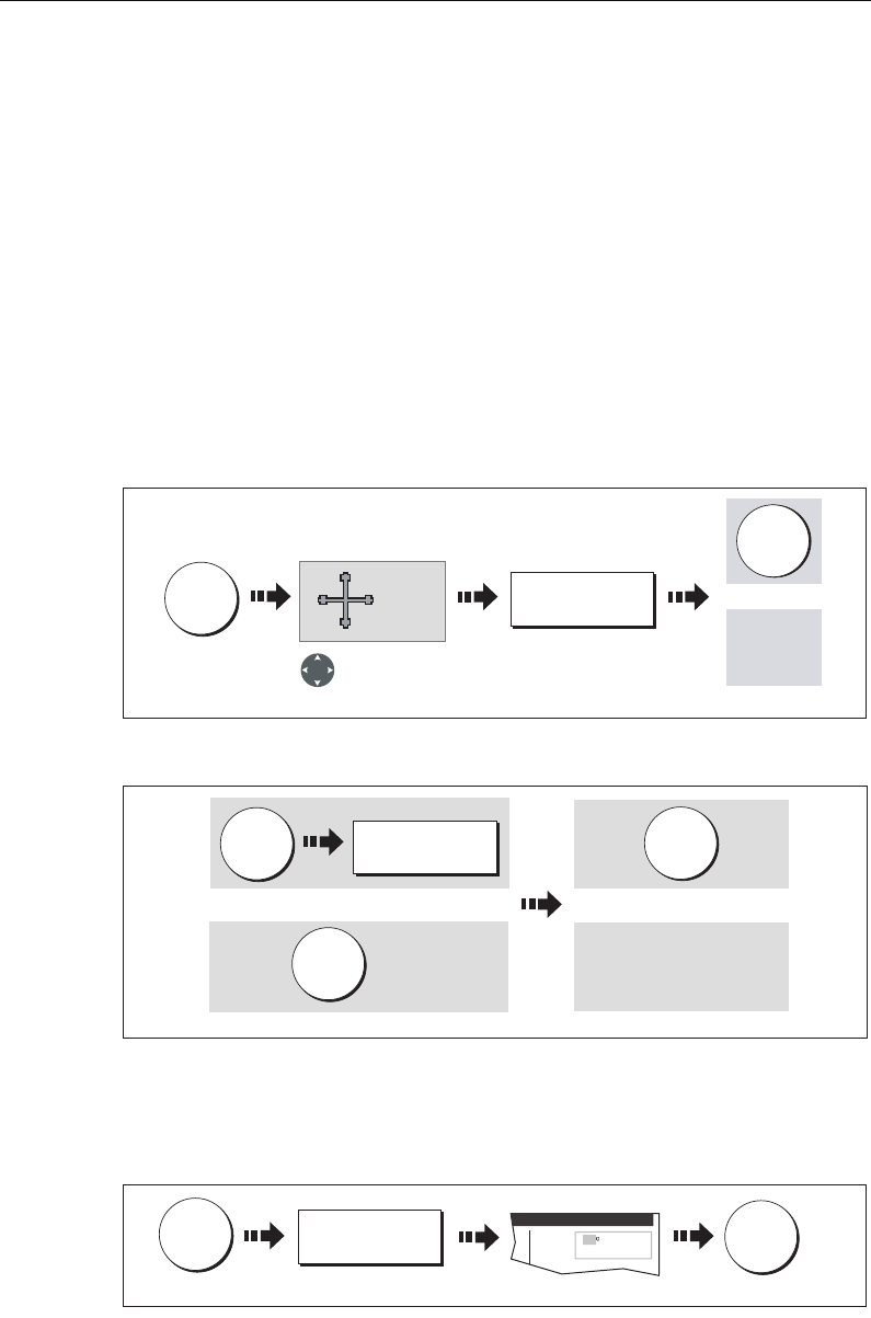
Chapter 3: Working with Waypoints 31
3.3 Placing a waypoint
A waypoint can be placed at:
• The cursor position.
• Your vessel’s position.
• At a position of your choosing (using lat/lon or Loran TD coordinates between 800
N/S).
When you are placing a waypoint, you can either accept the default or customize its
details. For more information see
page 34
.
Once a waypoint has been placed, you can view its details and edit them (if necessary).
For more information, see
page 33
and
page 34
.
... at the cursor
... at your vessel’s position
If the system cannot determine your position, a warning is displayed and the waypoint
is not placed.
... at a known position
WPTS
MOB
WAYPOINT AT
CURSOR
D7457-2
OK
Move cursor to
required position
for waypoint Accepts default
Or
Wait 4 secs
WAYPOINT AT
VESSEL
WPTS
MOB
D7458_2
WPTS
MOB x2
OK
Accepts default
Wait 4 secs
Or
Or
WPTS
MOB
WAYPOINT AT
LAT/LON...
50'.838N
01o06'.331W
Position:
Place Waypoint
50
D7459_2
OK
Enter position x 2
81221_4.book Page 31 Tuesday, February 28, 2006 5:24 PM
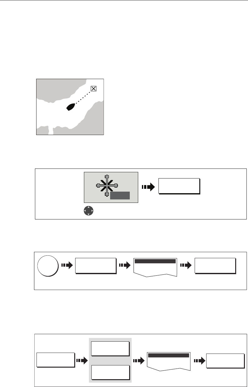
32 C-Series Display Reference Manual
3.4 Navigating to a waypoint
This section explains how to start and stop navigating to a waypoint. When you
navigate to a waypoint or to the cursor position, the data is sent on NMEA 0183 and
SeaTalk and can be used by an autopilot, if connected. For more information on
navigation, see
page 56
.
Start navigating to a waypoint
You can navigate to a waypoint using the cursor, via the
WPTS MOB button or by selecting the GOTO option.
Once navigation is active, the waypoint symbol is
surrounded by a box and a dashed line appears between
your boat and the waypoint.
If required you can display navigation details for the
active waypoint in the data bar (see
page 180
).
...using the cursor
To navigate to a waypoint using the cursor, when a chart or radar application is active:
...via the WPTS MOB button
To navigate to a waypoint using the WPTS/MOB button when any application is active:
.... by selecting the GOTO option
You can navigate to a waypoint using the GOTO option when a chart application is
active and the top level chart soft keys are displayed:
D8285_1
GO TO WAYPOINT
D7461_4
WPT
Position cursor over
waypoint to go to.
D6559-3
WPTS/
MOB
GOTO WAYPOINT
OPTIONS ... GOTO WAYPOINT
Select required waypoint
Waypoint List
GO TO ...
D7503_2
Select required waypoint
GOTO WAYPOINT
Or
GOTO CURSOR
GOTO WAYPOINT
OPTIONS...
Waypoint List
81221_4.book Page 32 Tuesday, February 28, 2006 5:24 PM
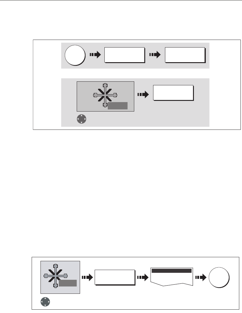
Chapter 3: Working with Waypoints 33
Stop navigating to a waypoint
If at any time you wish to stop navigating towards the selected waypoint:
Once navigation is no longer active, the waypoint symbol returns to its normal
unboxed state and the dashed line between your boat and the waypoint is removed.
3.5 Viewing waypoint information
You can view the details of any waypoint that you have placed, by either selecting it
with the cursor (in radar and chart windows) or by selecting it on the waypoint list.
Once you are viewing a waypoint’s details, a variety of editing and managing options
are available.
You can also display navigation details for the active waypoint in the data bar (see
page 180
).
...using the cursor
To view the details of a waypoint that is not active.
Note:
Details of the waypoint that you are currently navigating to, can be accessed via
the waypoint list as described below.
...using the waypoint list
The waypoint list shows all the waypoints that have been placed (including the active
one), and displays details of the selected waypoint:
Note:
Temperature and depth are only captured (if available) for waypoints placed at
your vessel’s position.
D7505-1
WPTS/
MOB
GOTO WAYPOINT
OPTIONS... STOP GOTO
WPT
Or:
Position cursor over
active waypoint.
STOP GOTO
D7505-2
WPTS/
MOB
GOTO WAYPOINT
OPTIONS... STOP GOTO
Or
Position cursor over
active waypoint.
STOP GOTO
WPT
EDIT WAYPOINT
D7506_2
Waypoint details displayed
Position cursor
over waypoint
OK
To exit way-
point list
WPT
Edit Waypoint
81221_4.book Page 33 Tuesday, February 28, 2006 5:24 PM
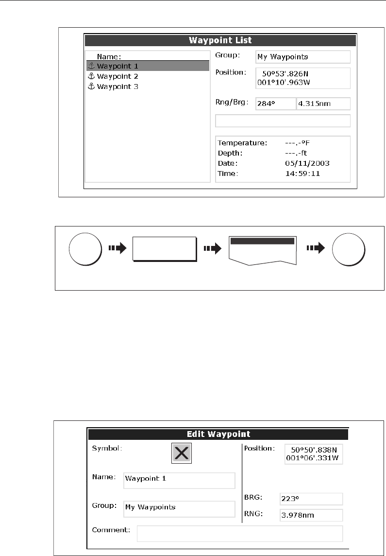
34 C-Series Display Reference Manual
To access the waypoint list:
3.6 Editing a waypoint
Once a waypoint has been placed it can be edited in a variety of ways. You can:
• Change the waypoint details - name, symbol, group or add a comment.
• Move a waypoint.
•Erase a waypoint.
• Change the default symbol and group of newly placed waypoints.
D6560-2
Waypoint List
D7507-2
WPTS/
MOB
REVIEW AND EDIT
WAYPOINTS...
Select required waypoint
OK
To exit way-
point list
D6561-1
D6561-2
81221_4.book Page 34 Tuesday, February 28, 2006 5:24 PM
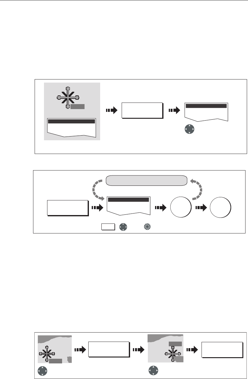
Chapter 3: Working with Waypoints 35
Changing waypoint details
When a waypoint is created it is assigned a default name, symbol and group. You can
change these details to suit your needs and add a comment if required. This is
particularly useful when you are managing large numbers of waypoints.
To change the details of a waypoint:
1. Select the detail you wish to edit:
2. Edit the selected detail:
Note:
If you make a mistake whilst editing, press CANCEL.
Moving a waypoint
You can move any waypoint (except the active one) to a new position. There are two
methods of moving a waypoint:
... by entering new coordinates
If you know the new co-ordinates, bearing or range for the particular waypoint, you
can enter this information by editing the waypoint as described in the previous section.
... by dragging the waypoint to a new position
Note:
To abandon the move, press CANCEL.
Edit Waypoint
D8286-1
WPT
Or
VIEW AND EDIT
DETAILS
Waypoint List
Select required waypoint with
cursor or via waypoint list
Highlight field
for changing
Edit Waypoint
EDIT SYMBOL
Edit details as required using: To save
e.g.
To save and
exit editing
Soft key reflects
highlighted field
OK OK
Repeat for other fields, if necessary
,and/or
Soft key
D8287-1
D8288-1
WPT
MOVE WAYPOINT PLACE WAYPOINT
Select waypoint
for moving
Drag waypoint
to new location
WPT
WPT
81221_4.book Page 35 Tuesday, February 28, 2006 5:24 PM
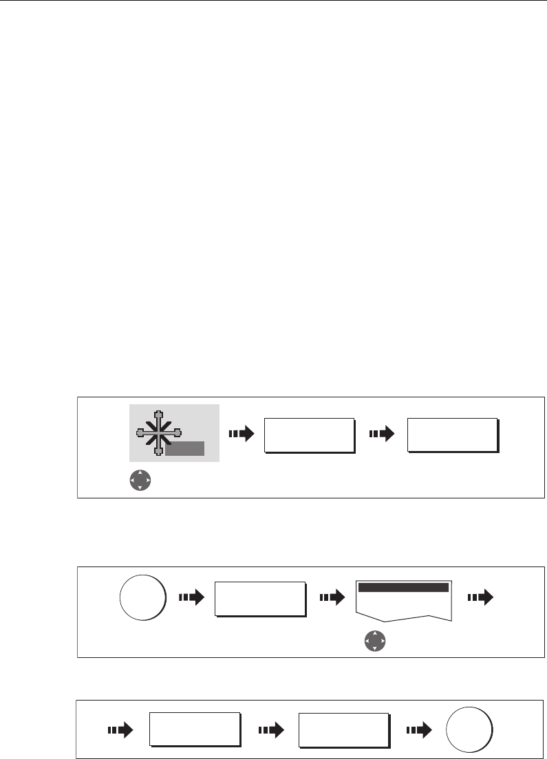
36 C-Series Display Reference Manual
CAUTION:
It is possible to move waypoints that are used in routes. In such instances, the
stored route will include the Waypoint in its new position. Ensure that this
does not present a navigation hazard.
Erasing a waypoint(s)
You can erase any waypoint on the system (including groups of waypoints) except:
• The active waypoint or
• Any waypoint used in a route.
Notes: (1)
If a route is hidden its waypoints can still be displayed. If you attempt to
erase a waypoint from a hidden route, a warning message will be dis-
played.
(2)
For details of erasing groups of waypoints, see page 41.
Erasing an individual waypoint
You can erase individual waypoints on screen or via the waypoint list.
...using the cursor
... using the waypoint list
1. Select the waypoint for erasing from the waypoint list:
2. Erase the selected waypoint:
D8289-2
WPT
ERASE WAYPOINT YES
Select waypoint
for erasing
Confirm the pop-up
message
REVIEW AND EDIT
WAYPOINTS...
Select waypoint
for erasing
WPTS
MOB
Waypoint List
D8843_1
D8844_)
YES
ERASE WAYPOINT
OK
81221_4.book Page 36 Tuesday, February 28, 2006 5:24 PM
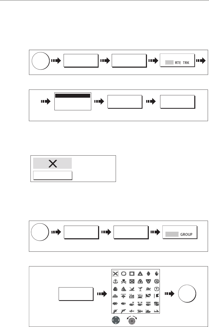
Chapter 3: Working with Waypoints 37
Erasing all waypoints
If you need to erase all your waypoints, you can use the ARCHIVE & TRANSFER soft
keys:
1. Select the ERASE FROM SYSTEM and the appropriate list:
2. Erase all waypoints:
Changing the default symbol or group
When you add a waypoint to your system it is assigned to the default group and given
the default symbol:
If these are not suitable, you can select an alternative symbol and group to be the
default. For an alternative group to be selected for the default, it must first be created -
see
page 39
.
1. Select either the default symbol or group:
2. Change the symbol or group default:
D8716-1
ARCHIVE AND
TRANSFER
ERASE FROM
SYSTEM...
SELECT LIST
DATA
W
PT
Select the WPT list
D8851_1
ERASE ALL
WAYPOINTS YES
Waypoint Group 1
Waypoint Group 2
Waypoint Group 3
System Waypoint List
System waypoint list
displayed
D6658-2
Default Symbol
Default Group
My Waypoints
D8290-1
WPTS
MOB
REVIEW AND EDIT
WAYPOINTS...
SET DEFAULT SYM
& GROUP...
SET UP DEFAULT
Toggle to required option.
Default displayed.
S
YMB
D8291-1
EDIT DEFAULT
Select required
default symbol
To save
OK
Symbol
Or
81221_4.book Page 37 Tuesday, February 28, 2006 5:24 PM
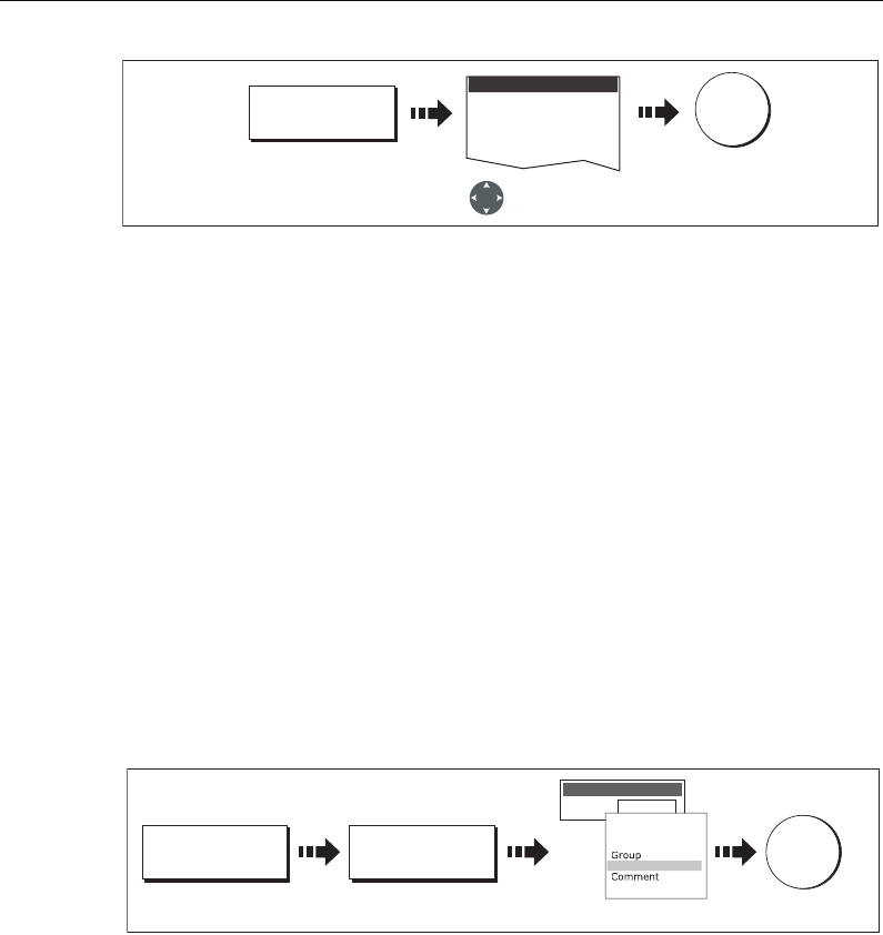
38 C-Series Display Reference Manual
Note:
To abandon the symbol or group default change, press CANCEL.
3.7 Sorting the waypoint list
If your system contains a large number of waypoints, you can sort your waypoint list to
make it easier to locate a particular waypoint.
The waypoint list can be sorted by:
• Name (default)
• Range (closest first)
•Symbol
• Group name
•Date
• Comment
•Depth
To sort the waypoint list:
3.8 Organising waypoints into groups
Provided that you have not changed the default group, all waypoints are automatically
placed in the default “My Waypoints” group when they are created. In order to make
your waypoints easier to manage, you can organize them into groups of your choice.
When fishing, for example, you may only wish to see the waypoints that indicate good
fishing sites. Other waypoints, say, for racing, would be superfluous at this time.
Note:
A waypoint cannot be placed in multiple groups
Displaying the waypoint group list
To display the group list with its options:
D9055-1
Select required
default group
EDIT DEFAULT
To save
OK
Group
Group List
D8292-1
SORT LIST SELECT SORT
OPTION
Save
OK
Select sort method
Range
SORT LIST BY
Order by:
Name
Range
Symbol
Depth
Dat
e
81221_4.book Page 38 Tuesday, February 28, 2006 5:24 PM
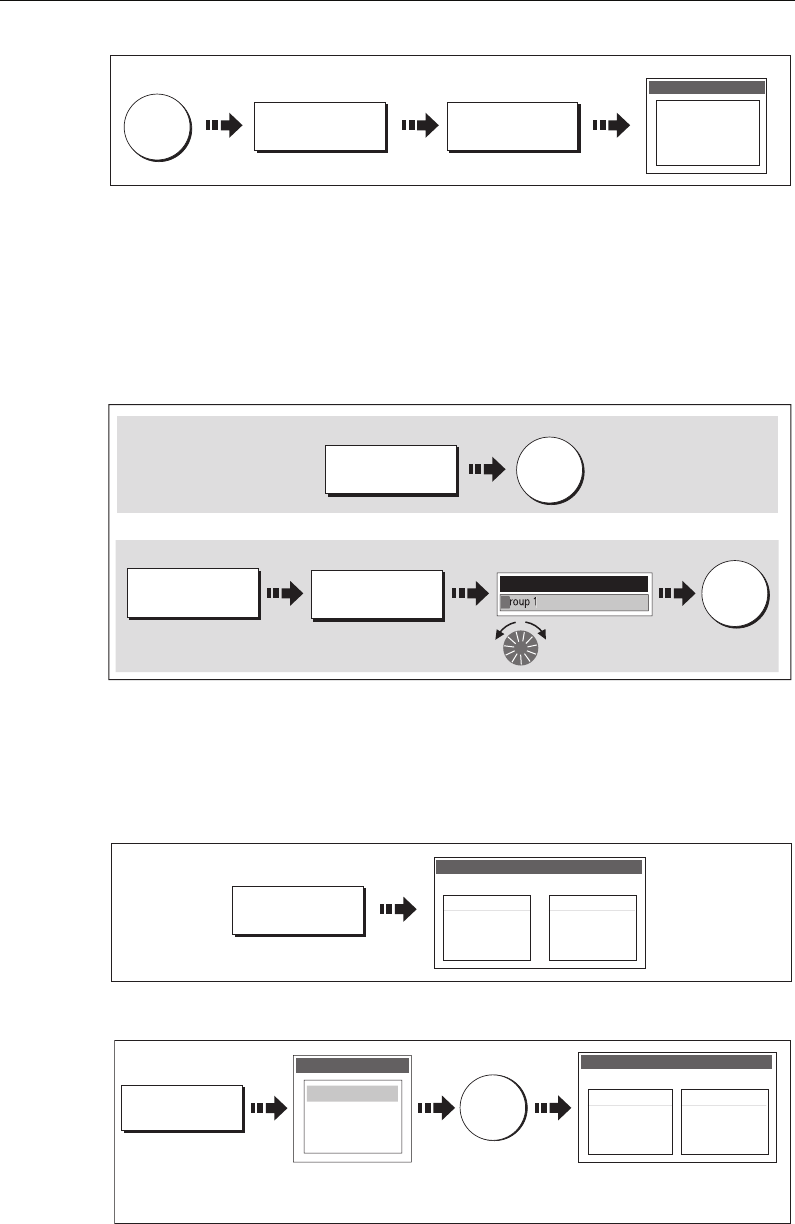
Chapter 3: Working with Waypoints 39
You can now make a new waypoint group, or erase, move or rename existing groups.
Making a new waypoint group
To create a new waypoint group:
1. Display the group list (see above).
2. You can now either:
Moving waypoints between groups
Waypoints can be easily moved between groups:
1. Display the group list (see
page 38
).
2. Display the MOVE BETWEEN GROUPS option:
3. Determine the group that contains the waypoint to be moved:
D6885-3
WPTS/
MOB
REVIEW AND EDIT
WAYPOINTS ...
WAYPOINT
GROUPS ...
Deep fishing
Shallow fishing
Reef fishing
GROUP LIST
e.g.
D8293_1
MAKE NEW
GROUP...
OK
D8293_1
MAKE NEW
GROUP...
OK
Or
EDIT GROUP
NAME
OK
Edit name Save
MAKE NEW
GROUP...
MAKE NEW
GROUP...
OK
Make a new group and accept the default name:
Make a new group and customise the name:
NEW WAYPOINT GROUP
G
D8293_2
D8295_1
MOVE BETWEEN
GROUPS...
Fishing
GROUP LIST
My Waypoints
Waypoint 1
Waypoint 2
Waypoint 3
MOVE BETWEEN GROUPS
GROUP A GROUP B
D8297_1
OK
SELECT GROUP A
Deep fishing
Shallow fishing
Reef fishing
GROUP LIST
My
Wa
yp
oint
s
Waypoints in selected group
listed.
My Waypoints
Waypoint 1
Waypoint 2
Waypoint 3
MOVE BETWEEN GROUPS
GROUP A
Select group
containing waypoint
to be moved.
81221_4.book Page 39 Tuesday, February 28, 2006 5:24 PM
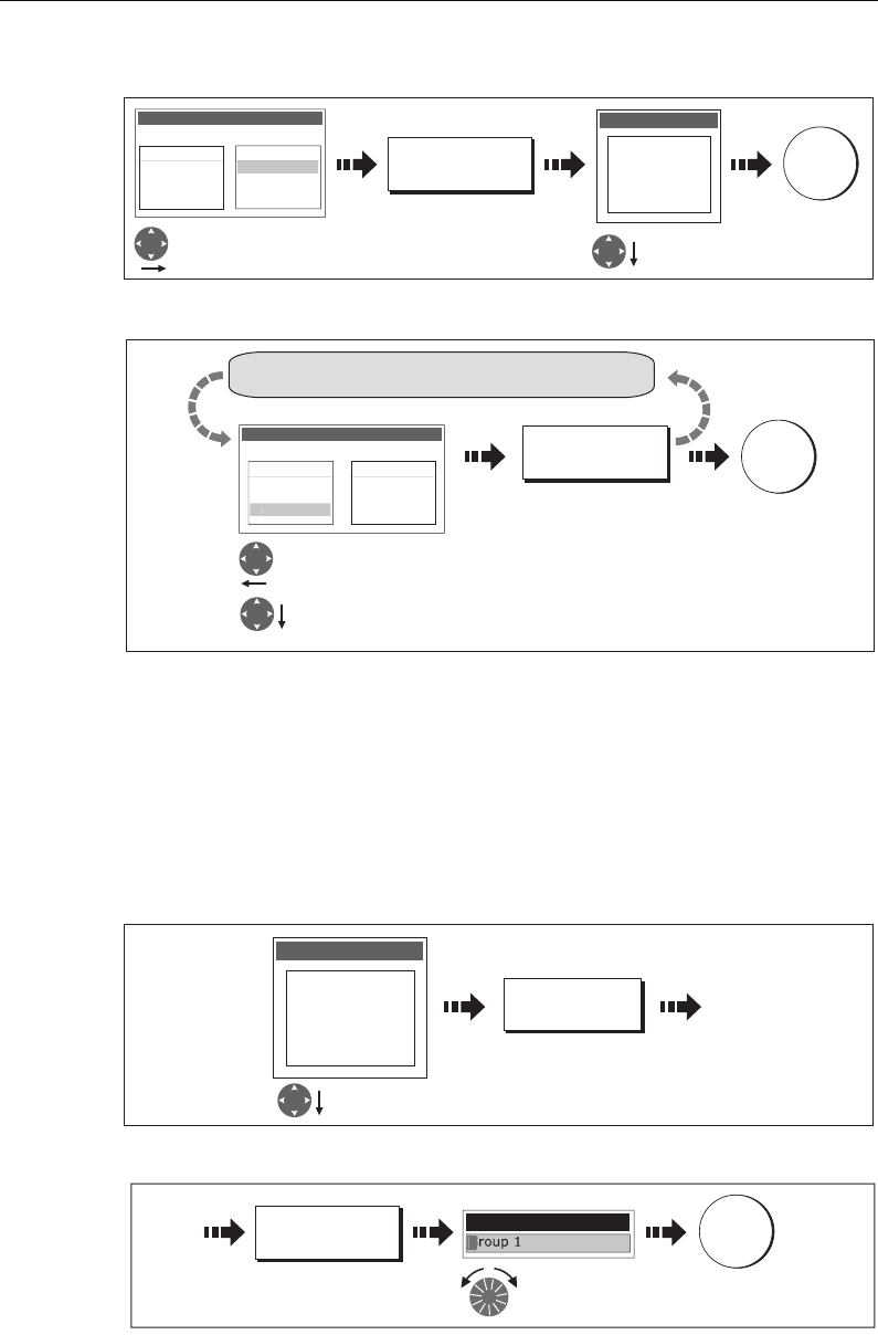
40 C-Series Display Reference Manual
4. Determine the group that the waypoint is to be moved to:
5. Select waypoint to be moved:
Note:
Alternatively, waypoints can be moved from Group B to Group A if required. The
soft keys reflect this accordingly.
Renaming an existing group
You can change the name of an existing waypoint group:
1. Display the group list (see
page 38
).
2. Select the group for renaming:
3. Edit the selected group name:
Note:
To revert to the original name whilst editing, press CANCEL.
D8298_1
OK
Fishing
GROUP LIST
My Waypoints
Waypoint 1
Waypoint 2
Waypoint 3
MOVE BETWEEN GROUPS
GROUP A GROUP B
SELECT GROUP B
My Waypoints
Deep fishing
Shallow fishing
Reef fishing
GROUP LIST
Move control to
Group B Select group to
add waypoint to
D8299_1
OK
Fishing
GROUP LIST
My Waypoints
Waypoint 1
Waypoint 2
MOVE BETWEEN GROUPS
GROUP A GROUP B
Waypoint
3
MOVE WAYPOINT
FROM A TO B
Move control to Group A.
Select required waypoint.
Repeat until all changes made
D8300_1
RENAME GROUP...
My Waypoints
Deep fishing
Shallow fishing
Reef fishing
GROUP LIST
Select required
group
D8301_1
Edit name
OK
EDIT GROUP
NAME
Save new
name
NEW WAYPOINT
G
81221_4.book Page 40 Tuesday, February 28, 2006 5:24 PM
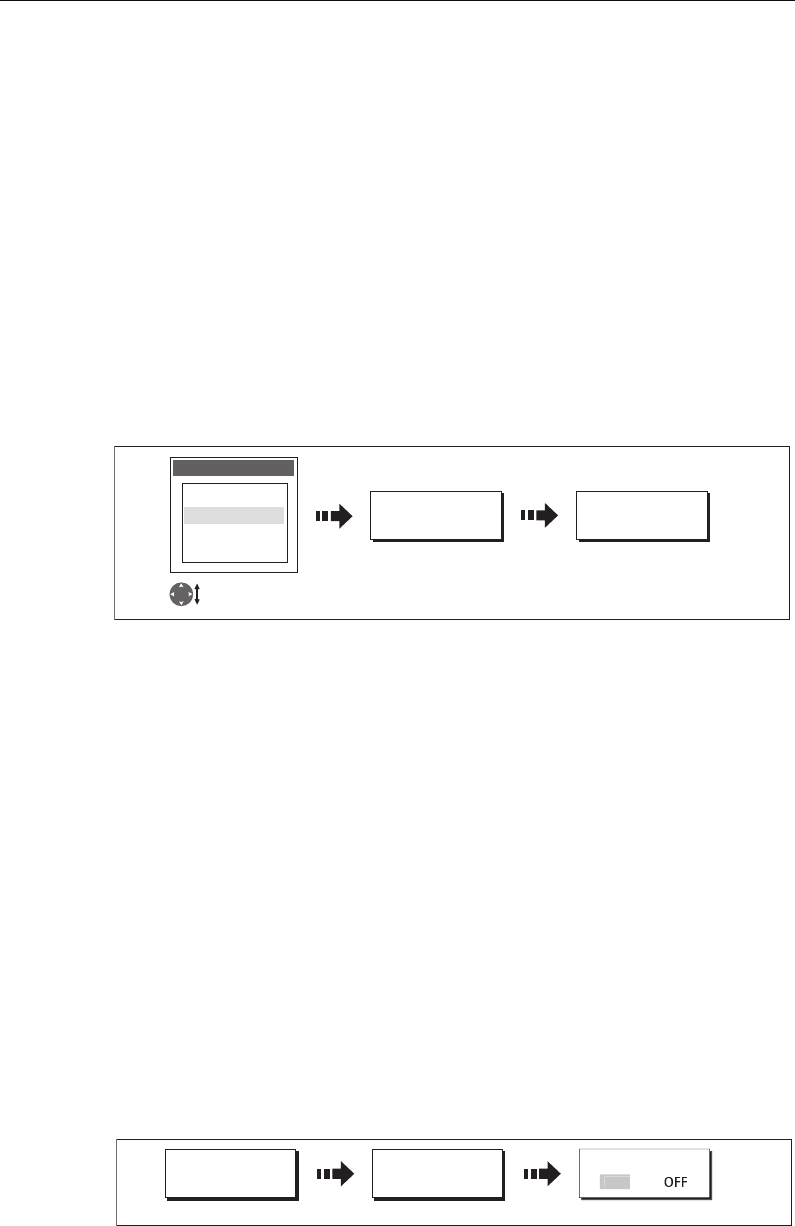
Chapter 3: Working with Waypoints 41
Erasing a group
You can erase any waypoint group from the system except the group containing the
active waypoint.
When a waypoint group is erased, the group name together with all of the waypoints
in that group are erased from the system with the exception of:
• ‘My Waypoints’ - the waypoints contained within this group are deleted but the
group name remains.
• Waypoints used in routes within your system.
You should therefore ensure that any individual waypoints that you want to keep
(which are not part of a route), are moved before their group is erased.
1. Display the group list (see
page 38
).
2. Select and erase the group:
Note:
Waypoint groups can also be erased via the ARCHIVE AND TRANSFER function
as described on page 37. For details of how to erase waypoint groups from a card, see
page 21.
3.9 Controlling waypoint display
When you have placed many waypoints on your system, it may become difficult to
easily interpret chart or radar information. This is particularly the case if you have many
waypoints in a small area. There are a number of ways that you can control the display
of waypoints and waypoint information in chart and radar windows. These are:
• Show or hide waypoints with a particular symbol.
• Show or hide waypoints belonging to a specific group.
• Show or hide all of the waypoint names.
• Show or hide the index of a waypoint within a route - chart only (see
page 87
).
Show/hide waypoint names
You can show or hide all waypoint names if required:
D8302_1
ERASE GROUP... YES
My Waypoints
Deep fishing
Shallow fishing
Reef fishing
GROUP LIST
Highlight page
set for editing
Confirm the pop-up
message
D8306_1
PRESENTATION... SHOW/HIDE
WAYPOINTS...
WAYPOINT NAME
Select status
O
N
81221_4.book Page 41 Tuesday, February 28, 2006 5:24 PM
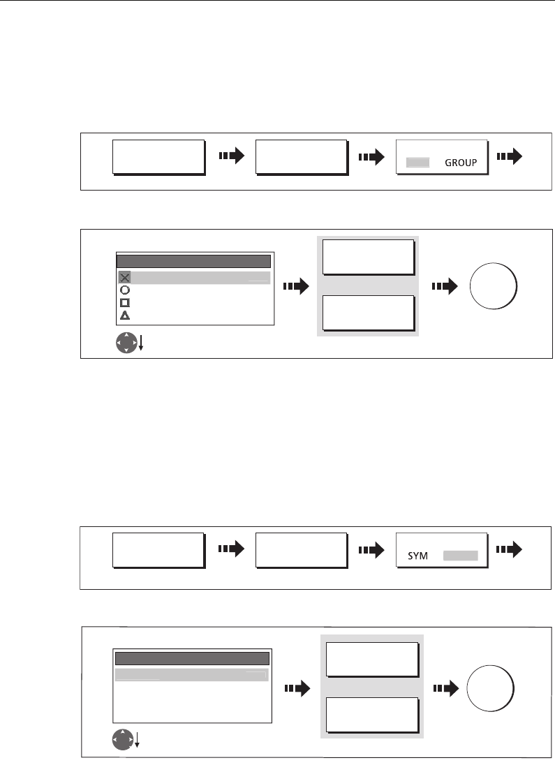
42 C-Series Display Reference Manual
Showing/hiding waypoint symbols
You can define which waypoint symbol types are shown/hidden in the radar or chart
application:
1. Display the SHOW BY SYMBOL option:
2. To change the status (show or hide) of a symbol type:
Note:
Waypoints in an active route are always displayed, regardless of whether the
display is set to show or hide.
Showing/hiding waypoint groups
You can define which waypoint symbol types are shown/hidden in radar or chart
applications:
1. Display the SHOW BY GROUP function.
2. To change the status (show or hide) of a waypoint group:
Note:
Waypoints in an active route are always displayed, regardless of whether the
display is set to show or hide.
D8839_1
PRESENTATION... SHOW/HIDE
WAYPOINTS...
SHOW BY
Select SYM
S
YM
D8304_1
OK
Select status
Fish HIDE
Ra SHOW
Day HIDE
SHOW BY SYMBOL
M
S
H
OW
Select required group
ON CHART
SHOW HIDE
ON RADAR
SHOW HIDE
Or
D8721_1
PRESENTATION... SHOW/HIDE
WAYPOINTS...
SHOW BY
Select GROUP
GROU
P
D8305_1
OK
Select required group
Fishing SHOW
Racing SHOW
Day trips HIDE
SHOW BY GROUP
My Waypoints
S
H
O
W
Select status
ON CHART
SHOW HIDE
ON RADAR
SHOW HIDE
Or
81221_4.book Page 42 Tuesday, February 28, 2006 5:24 PM

Chapter 4: Using the Chart 43
Chapter 4: Using the Chart
4.1 Important
Safety
When using your chartplotter you should always check that a route is safe. Zoom in to
check for hazards, such as small shoals, that may not be shown on a smaller scale
chart.
Until you are familiar with interpreting the chart display, you should take every
opportunity to compare the displayed objects with visual targets, such as buoys and
coastal structures. You should practice harbour and coastal navigation during daylight
and in clear weather conditions. The simulator mode can also be used to help you gain
experience.
It is strongly recommended that before you use your chart application, that you read
and understand
Chapter 3:Working with Waypoints
.
CAUTION:
The equipment should not be used as a substitute for good navigational
practice nor for official government paper charts. Do not use the chart before
you have read this chapter.
Chart functionality
1. To access full functionality, your chart application requires position and heading
data from your boat’s Global Positioning System (GPS).
2. Your C-Series Display has a built in world map, but to use your Display as a naviga-
tion aid, you will need detailed information for the area you wish to navigate. This
information comes in the form of a chart card and is available from Navionics (see
the
Important Information
section at the front of this manual for details). For full
information on installing and removing chart cards refer to
page 17.
3. For your GPS and chart to correlate accurately with your paper charts, they will
need to be using the same datum. The default datum for your display is WGS84. If
this is not suitable, you can change the setting via the Chart Setup menu (see
page 91
). When you adjust the datum of the C-Series Display, a Raymarine GPS will
automatically correlate. If you have a third party GPS, you will need to correlate this
separately.
4. For the Automatic Identification System (AIS) to function you should have a suit-
able AIS receiver connected.
81221_4.book Page 43 Tuesday, February 28, 2006 5:24 PM

44 C-Series Display Reference Manual
Chart cards
To use your C-Series Display as a navigation aid, charts with the appropriate level of
detail for the geographic area you wish to navigate are required. The charts are
available in electronic format on Navionics Chart cards. Details of these cards and how
to obtain them is given on
page iii
.
When archiving data, Raymarine recommends that you only use SanDisk brand CF
memory cards. Other brands of CF memory cards may not work in your C-Series
Display.
4.2 Uses of the chart application
Once the heading and position data is available you can use your chart to:
• Find out where you are (see
page 46
).
• Interpret your surroundings (see
page 47
).
• Measure the distance and bearing between two points (see
page 55
).
• Place waypoints at specific locations (see
page 56
).
• Navigate to a specific point (see
page 56
).
• Build and follow a route (see
page 59
).
• Monitor where you are going (see
page 74
).
• Distinguish between fixed and moving objects using radar overlay (see
page 76
).
• Record where you have been (see
page 78
).
• Manage and edit routes and tracks (see
page 68
and
page 81
).
• View AIS data (see
page 54
).
Facilities are also provided to customize your chart application to your own particular
requirements and circumstances. You can:
• Alter the way the chart is drawn in relation to your boat and the direction you are
travelling in (chart orientation and motion mode).
• Manage and edit chart data you have entered.
• Control the level of detail displayed on-screen.
Note:
To change the data displayed in the data bar at the top /side of the screen,
please refer to page 179.
81221_4.book Page 44 Tuesday, February 28, 2006 5:24 PM
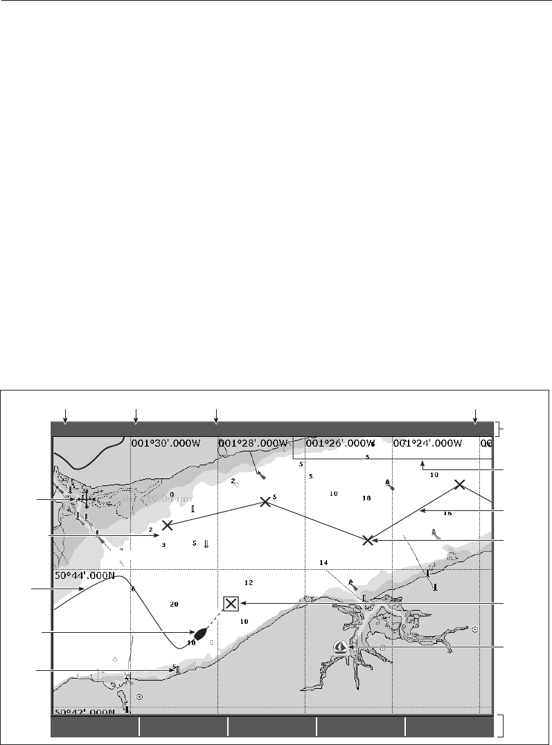
Chapter 4: Using the Chart 45
4.3 Viewing the chart
You will normally view your chart with the vessel on screen and motion mode ‘active’.
When motion mode is active, as your vessel moves, the chart is redrawn to keep the
vessel on screen. When you zoom the chart in active mode, the chart zooms about your
vessel position.
Alternatively, you may be planning a journey and do not want the chart to redraw as
your vessel moves. You can suspend the active motion mode by using the cursor to pan
the chart (see
page 46
) or by selecting FIND CURSOR.
When motion mode is suspended, the mode is shown in the status bar in parenthesis
e.g. (RELATIVE MOTION); zoom operates about your cursor position.
Provided the necessary data to ascertain your vessel’s position is available, you can
activate the motion mode, by selecting FIND SHIP.
4.4 The chart display
The main features of the chart display are as follows:
FIND
SHIP CURSOR GOTO... ROUTES... TRACKS... PRESENTATION...
4nm North-Up (Relative Motion) Local
Gully Ridge
Creek point
Port point
Portside
Chart
boundary
Chart range Chart orientation Motion mode
Status
bar
Cursor
Route
Waypoint
name
Current
position
Waypoint
Track
Carto-
graphic
object
Active
waypoint
Soft
keys
D6605_2
Chart view
Port
Services
81221_4.book Page 45 Tuesday, February 28, 2006 5:24 PM
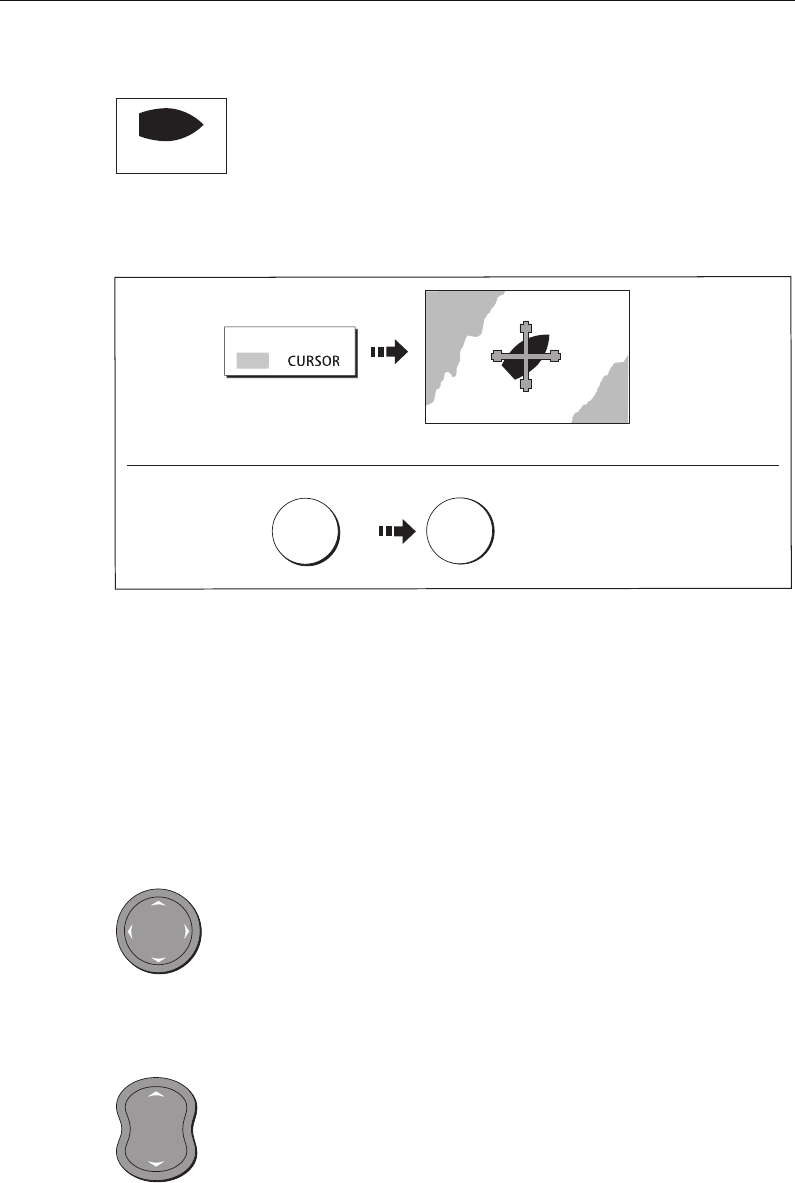
46 C-Series Display Reference Manual
4.5 Where am I on the chart?
Your current position is represented on screen by a boat symbol. If
neither heading nor COG data is available, the vessel is shown as a
solid circle.
If positional data has been selected for display (see
page 180
), your position will be
displayed in the data bar under VES POS.
Note: For more information on waypoints, please refer to the Waypoint Chapter.
4.6 Moving around the chart
To move around the chart and display the area required at the appropriate scale, use a
combination of zooming and panning.
Note:
When you pan the chart, or when you change the scale in autorange mode; the
motion mode is suspended - see page 45 and page 85.
Panning
Panning moves the chart that is displayed to a different area. To pan a
chart, simply press the appropriate arrow (left/right, up/down) on the
trackpad. When the cursor reaches the edge of the screen, the chart pans.
Note:
When you pan the chart, active motion mode is suspended.
Zooming in/out
When you zoom in, the chart scale changes to show a smaller area in more
detail. Conversely, if you zoom out the chart area displayed is increased
but the detail is reduced.
Note:
The cartographic detail available on charts varies according to the chart and the
chart scale. Some areas provide detail at smaller scales than others.
D6627-1
Boat symbol
D8714_1
FIND
S
HIP
Chart redraws with boat at centre
Toggle to FIND SHIP
If you cannot see your boat:
WPTS
MOB OK
Accepts default
(or wait 3 seconds)
x2
To mark your current position:
D6583-3
D6585-2
D6585-1
RANGE
IN
OUT
81221_4.book Page 46 Tuesday, February 28, 2006 5:24 PM
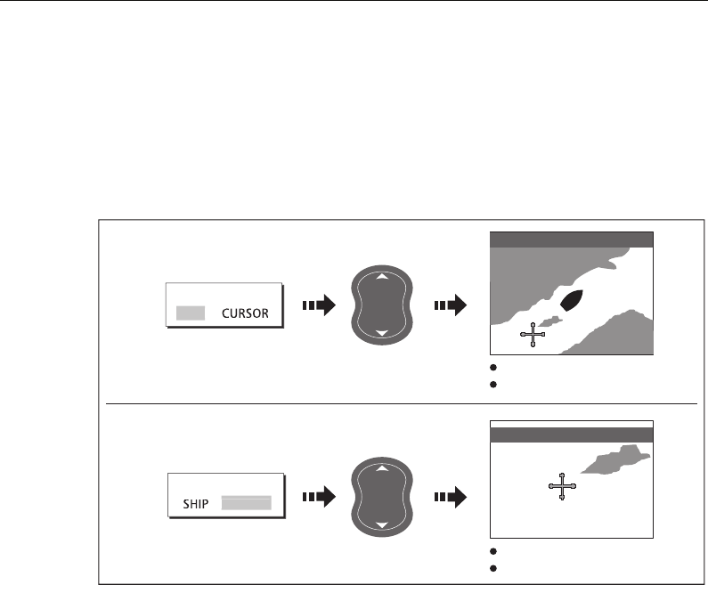
Chapter 4: Using the Chart 47
A feature of the chart is ‘autoscale’. If you select a chart scale that does not have
cartographic detail in some areas, the chart will use the most detailed level available
for the surrounding area and stretch it to fit the selected scale. This means that you will
never have blank or hatched areas on your screen. However there may be some mis-
alignment of objects which cross the chart boundary in this area.
To zoom in/out:
4.7 Additional information on the chart
Depending on the chart card you are using, you will also be able to view some or all of
the following addition information:
• Details of each cartographic object that is marked on the chart, including source
data for structures, lines, open sea areas etc.
• Details of ports, port and business services, tidal and current information, wrecks
and obstructions.
Note:
For full details of the features available with each chart card type, please refer to
the Navionics website:
www.navionics.com or navionics.it.
To change the set up options to control how selection of object information operates -
see
page 90
.
... about your boat:
... about the cursor:
Chart zooms in/out on your boat
Motion mode active
Chart zooms in/out on the cursor
Motion mode inactive
e.g.
e.g.
D9006_1
FIND
FIND
SHIP
CU
R
SOR
FIND SHIP selected
FIND CURSOR selected
D6585-1
OUT
IN
RANGE
D6585-1
OUT
IN
RANGE
3nm N-UP RM Sys
1nm N-UP (RM) Sys
81221_4.book Page 47 Tuesday, February 28, 2006 5:24 PM
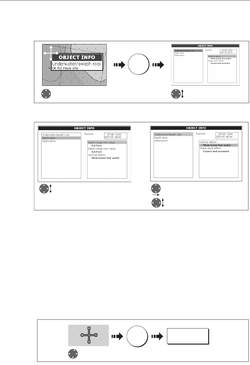
48 C-Series Display Reference Manual
Displaying details of objects and features
To view details:
If the object you have selected has more than one subject area:
The soft keys provide controls to:
• Locate the nearest waypoint, port, port service, tidal and current stations, wreck or
obstruction, to the selected position.
• Search for a named port.
• View detailed data for the selected port, tidal station or current station.
Finding nearby features and services
You can locate the nearest waypoint, port, port service, tidal and current stations,
wreck or obstruction, to the cursor position.
1. Select position for the FIND NEAREST option:
2. Select the feature or service. For ports, you can select a specific service and for a
selected port or business service you can find the nearest ports:
D 6771-2
Move cursor over object, to
display basic information.
OK
More detailed information for
selected object displayed.
D 8308_1
Highlight the required subject area.
Details displayed in right-hand column.
Scroll through detailed list
Move control to right hand column
D8260_1
OK
Move cursor to
required position
FIND NEAREST...
81221_4.book Page 48 Tuesday, February 28, 2006 5:24 PM
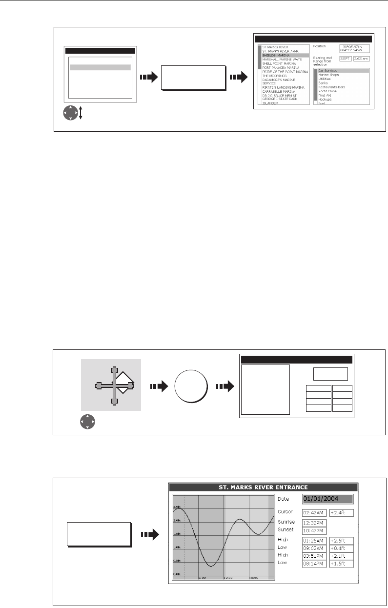
Chapter 4: Using the Chart 49
Once located, you can use the soft keys and trackpad to:
• Display detailed data for services at the listed ports.
• Show the selected item on the chart.
• GOTO the selected waypoint
• View tidal/current data for the selected tidal/current station.
Displaying details of tides
You can display details of tides by:
• Selecting the appropriate tidal diamond (see below) or
• Via the FIND NEAREST function (see
page 48
).
...Using the tidal diamond
1. To display numerical tidal information:
You can now view additional tidal data.
2. To display additional tidal data including a tidal curve:
D8310_1
FIND
FIND NEAREST...
WAYPOINTS
PORT SERVICES
TIDE STATIONS
CURRENT STATIONS
WRECKS
OBSTRUCTIONS
P
ORTS
SELECT PORT
16 nearest to cursor in selected
category displayed.
Select required
category
T
D8311_1
OK
Position cursor
over tidal diamond
OBJECT INFO
ST MARKS RIVER
High
Low
High
Low
Position 30
0
04.700N
84
0
10.700W
01:25AM +2.5ft
09:02AM +0.4ft
03:51AM +2.1ft
08:14AM +1.5ft
Tidal information displayed
D6782_3
TIDAL DATA
Detailed data is shown for the selected time
(red, dashed, vertical line).
81221_4.book Page 49 Tuesday, February 28, 2006 5:24 PM
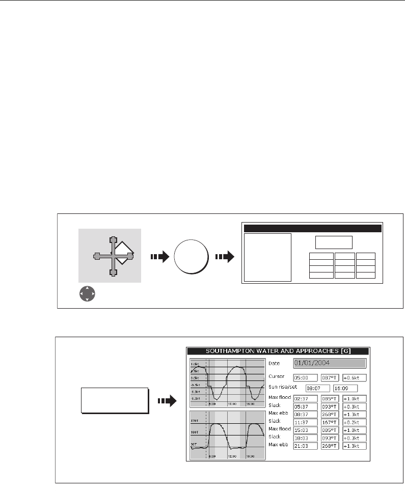
50 C-Series Display Reference Manual
You can now:
• Move the time-selector, using the trackpad/rotary control.
• Change the displayed date, using the soft keys.
Displaying details of currents
You can display details of currents by:
• Selecting the appropriate current diamond (see below) or
• Via the FIND NEAREST function (see
page 48
).
... using the current diamond
1. To display numerical current information:
2. To display additional current data including a current curve:
You can now:
• Move the time-selector, using the trackpad/rotary control.
• Change the displayed date, using the soft keys.
Displaying details of port services
You can display details of port services by:
• Using the port search option (see below).
• Selecting the appropriate port symbol (see
page 52
).
• Using the FIND NEAREST function (see
page 48
).
D8313_1
OK
Position cursor over
current diamond
OBJECT INFO
FOUR MILE POINT
Ebb
Flood
Ebb
Flood
Position 30006'.700N
84012'.700W
05:41AM +187.0
01:08AM +358.0
06:17AM +0.0
11:30AM +358.0
0.5kt
0.2kt
0.0kt
0.2kt
Current information displayed
C
D7513_2
CURRENT DATA
Detailed data is shown for the selected time.
81221_4.book Page 50 Tuesday, February 28, 2006 5:24 PM
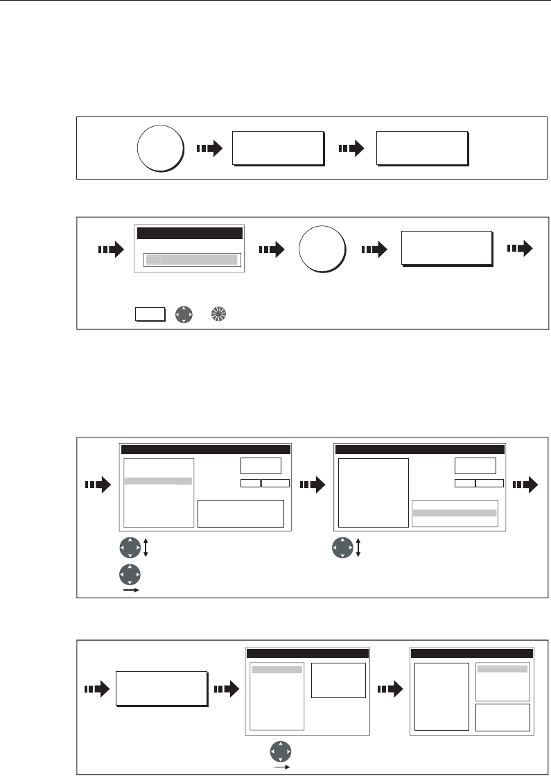
Chapter 4: Using the Chart 51
... using the port search option
The port search option allows you to specify the name a port and display its services:
1. Select the edit name option:
2. Enter the port name (or the first few characters of the port name) and search:
Note:
For help with entering text into a dialog box, please refer to page 11.
3. If the search returns more than one port, you can select which port’s facilities and
services you want to display.:
i. Select a particular port and its service:
ii. Display details of the selected service:
4. You can now centre the screen on the selected port by pressing SHOW ON CHART.
D8314_1
OK
SEARCH BY NAME EDIT NAME
D 8309_1
SEARCH BY NAME
Enter Port Name
GA
Enter port name (or part of)
using:
OK
,or
Soft key
SEARCH
D8742_1
SELECT PORT
GANDERS MARINE
GANDERS BASIN
Position
Bearing and
Range from
selection
29043.730N
84058.957W
Restaurants
Travel Agencies
Beauty Shops
3420T.007nm
G
ANDERS QUAY
SELECT PORT
GANDERS MARINE
GANDERS BASIN
GANDERS QUAY
Position
Bearing and
Range from
selection
29043.730N
84058.957W
Restaurants
Beauty Shops
3420T.007nm
Trave
l
Agencie
s
Highlight required port Highlight required service
Select highlighted port
D8743_1
VIEW DETAILS...
GANDERS QUAY - Travel Agencies
T
ravel A
g
encie
s
DAVIS TRAVEL
GANDERS QUAY - Travel Agencies
Travel Agencies
Tel: 1234567
1 High Street
Ganders Quay
Select service Details of service displayed
D
AVIS TRAVE
L
81221_4.book Page 51 Tuesday, February 28, 2006 5:24 PM
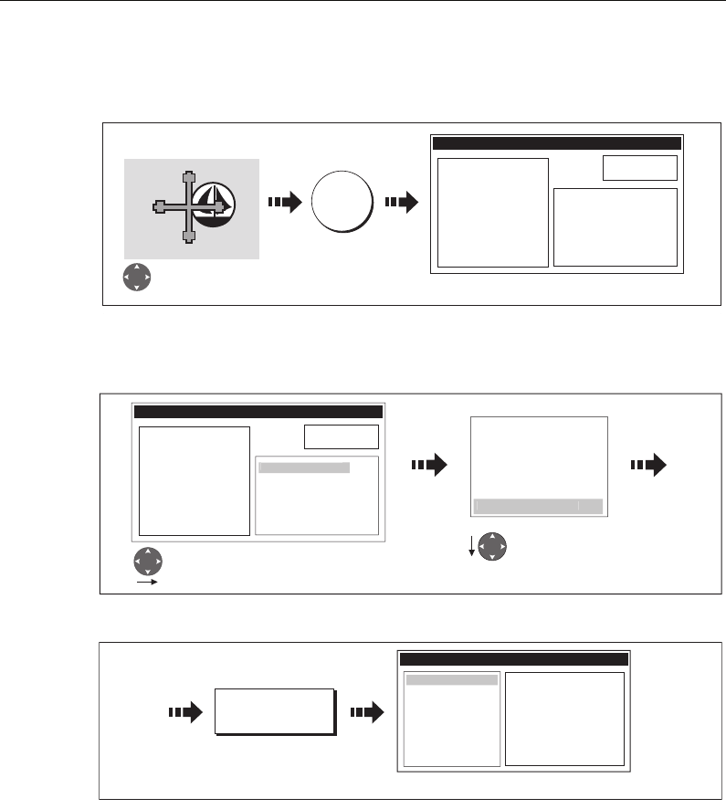
52 C-Series Display Reference Manual
... using the port symbol
The services available at a particular port can be displayed by selecting its symbol:
You can now view details of individual services:
1. Select required service:
2. Display service details:
Note:
This method is also used when using the SEARCH BY NAME and FIND NEAREST
functions.
D9099_1
OK
OBJECT INFO
RAINBOW HARBOR
Dredged area
Depth area
Position 29058'.147N
093052'.215W
General Services
Repair Services
Fuel
Other information
Services for selected port displayed
Select appropriate
port symbol
D9100_1
Highlight required
service
Water Transportation
Car Services
Utilities
Stores
Banks
R
estaurants-
B
ar
s
Move control to the utilities column
OBJECT INFO
RAINBOW HARBOR
Dredged area
Depth area
Position 29058'.147N
093052'.215W
Repair Services
Fuel
Other information
G
ener
al
Services
D8318_1
RAINBOW HARBOR - Restaurants-Bars
Ichibon Japanese Seafood
Landrys Restaurants Inc
Joes Crab Shack
Redfish Island
Restaurants-Bar
s
VIEW DETAILS...
Details of selected service displayed.
81221_4.book Page 52 Tuesday, February 28, 2006 5:24 PM
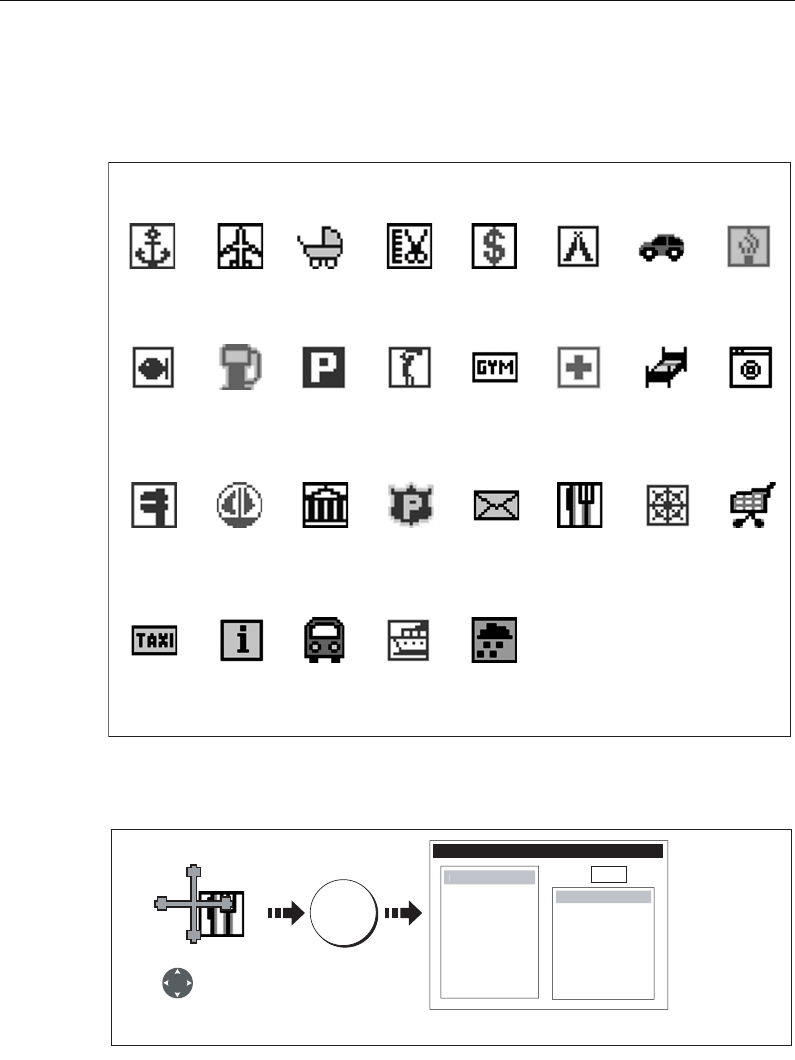
Chapter 4: Using the Chart 53
Displaying details of business services & points of interest
When a suitable chart card is installed the location of various business services and
points of interest are indicated by the following symbols:
You can view the name, address, telephone number, and type of business of an
individual service by selecting its symbol on screen:
Note:
If required, you can declutter your chart by either switching off the business ser-
vices symbols (via the Cartography Setup Menu) or by switching on the DECLUTTER
option (via the PRESENTATION soft key).
Business services/points of interest symbols
Airport Babysitting Barber Bank Camping Car hire
Fishing
equipment
Parking
Firemen
Gas/Petrol
MarinaNautical
repairs
LaundryHotelHospitalGym
Golf
Post OfficePoliceMuseum
Anchorage
Water
transport
TrainTourist
information
Taxi
station
ShopShip
repairs
Restaurant
Weather
station
D8226_1
D8264_1
OK
Select business
service symbol
e.g restaurant
OBJECT INFO
Land area
N
am
e
The Haven
Address
20 High Rd
Seaview
Isle of Wight
Phone
0123 45678
Position xxx
Po
int
o
f Interes
t
Eating p
l
ace
s
Additional information displayed
81221_4.book Page 53 Tuesday, February 28, 2006 5:24 PM
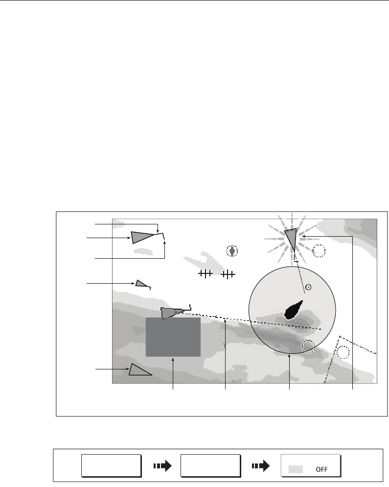
54 C-Series Display Reference Manual
Displaying vessel identity (AIS)
If you have an AIS receiver fitted to your system, you can use the AIS feature to:
• Display targets for any other AIS equipped vessels.
• Display voyage information being broadcasted by these targets i.e. their position,
course, speed and rate of turn.
• Display basic or detailed information for each target vessel including safety critical
target data.
• Set up a safe zone around your boat.
• View AIS alarm and safety related messages.
This information is displayed in the form of an overlay and additional data is displayed
in a dialog box on your chart screen e.g.
To switch on AIS:
This feature can also be used in conjunction with the radar application. For full
information on how to use the AIS feature, please refer to
Chapter 11:Automatic
Identification System (AIS)
.
D9056_1
097°T
11.6kt
1.237nm
00h04m33s
Safety
critical data
Heading
Large
vessel
Direction
of turn
Small
vessel
COG/SOG
vector
Safe zone (defined by
distance or time)
Dangerous
target (flashes)
Sleeping
target
D9023_1
CHART LAYERS... AIS LAYER
PRESENTATION ON
81221_4.book Page 54 Tuesday, February 28, 2006 5:24 PM
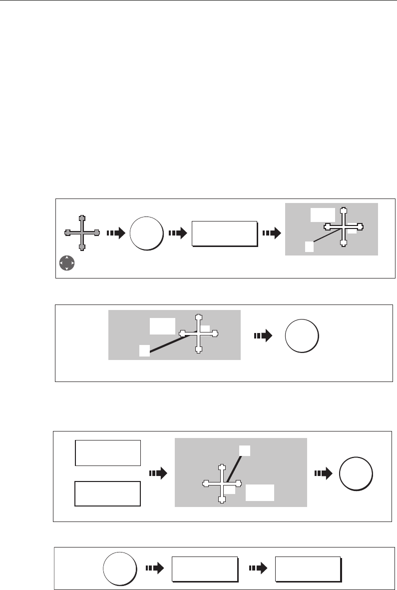
Chapter 4: Using the Chart 55
4.8 Measuring distances and bearings
... from your boat
You can determine the position, distance and bearing from your boat to the position of
the cursor by referring to the cursor position (Csr Pos) data in the databar.
... between two points on your chart
The ruler option of your chart application can be used to obtain an accurate
measurement of the distance and bearing between two points on your chart.
To position the ruler
1. Position the ruler starting point:
;
2. Position the ruler end point:
To reposition the ruler
To reposition either the start or end point of the ruler:
To clear the ruler
D6665-3
DATA
RULER
Position cursor
at start point. Range & bearing from A to B
displayed. ADJUST B highlighted.
A
B
065
0
T
0.18nm
OK
033oT
0.60nm
A
B
To fix new ruler
position
Move cursor to end point.
Distance and bearing displated.
D8321-1
OK
008
o
T
0.46nm
A
B
ADJUST A
ADJUST B
Or
Select which point to adjust Move cursor to new position
To fix new
ruler
position
D8322-1
D8323_1
CLEAR RULER
DATA RULER
81221_4.book Page 55 Tuesday, February 28, 2006 5:24 PM
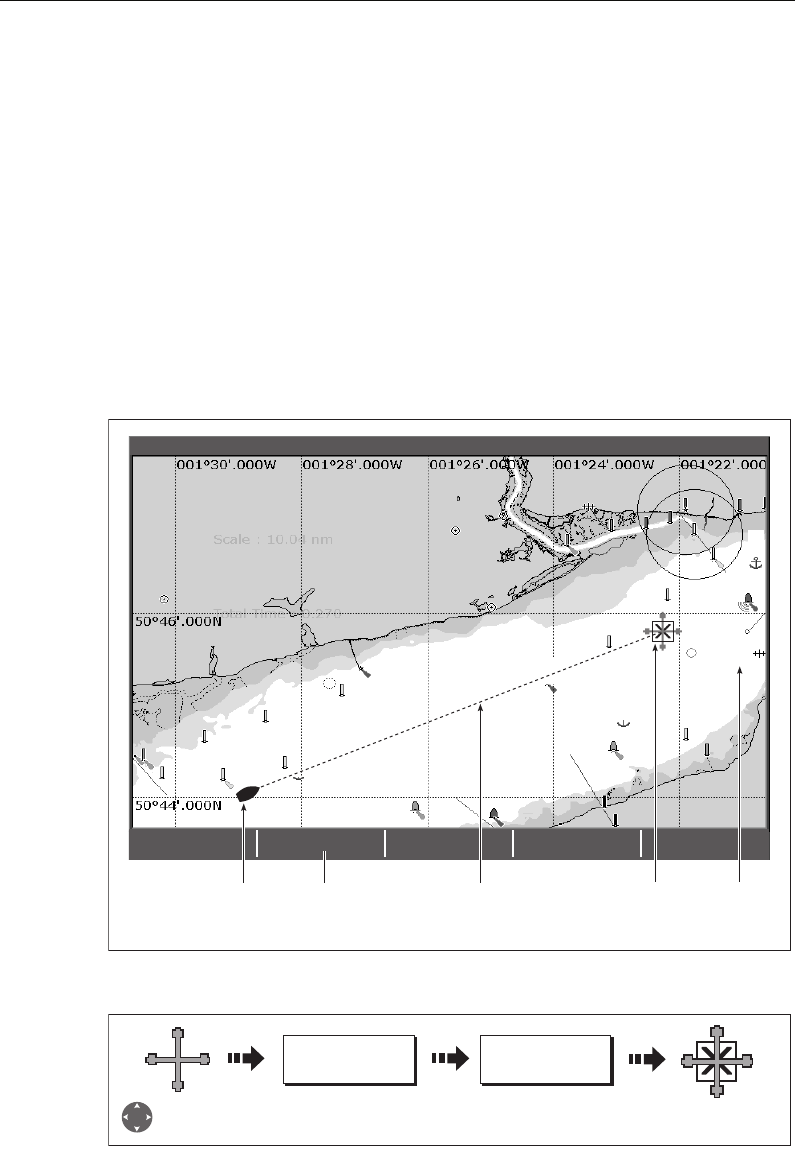
56 C-Series Display Reference Manual
4.9 Navigating to a specific point
You can use your chart to navigate to a specific point marked by the cursor (temporary
waypoint) or to a waypoint. If required you can display the largest chart scale possible
that will display both your boat and the target waypoint. When you navigate to a
waypoint or to the cursor position, the data is sent on NMEA 0183 and SeaTalk and can
be used by an autopilot, if connected. On arrival at the specified point a message is
displayed and an alarm sounds.
When you are steering manually, you can also use the chart to determine the bearing
or direction to steer.
Note:
If you are currently navigating a route or going to the cursor /waypoint, you
must press
STOP GOTO,
before the system can commence a new GOTO request.
To go to the cursor position:
Note:
This target waypoint is also identified on the radar
D6608-3
GOTO CURSOR
STOP GOTO RESTART XTE
4nm North-Up (Relative Motion) Local
Boat's heading changes
to follow course to
temporary waypoint
Press to stop GOTO
and remove
temporary waypoint
Dashed line
marking original
course of GOTO
Temporary waypoint
(within white box)
placed at cursor
Temporary
waypoint
name
GOTO...
D6493-2
GOTO CURSOR
Position cursor at
desired destination
Temporary waypoint
placed at the cursor.
81221_4.book Page 56 Tuesday, February 28, 2006 5:24 PM
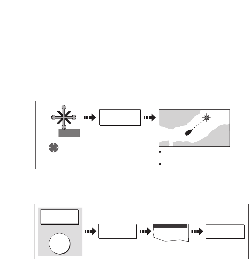
Chapter 4: Using the Chart 57
Go to an existing waypoint
You can navigate to an existing waypoint by either selecting the appropriate waypoint
on-screen with the cursor or by selecting it from the waypoint list:
Note:
For more information on navigating with Waypoints, please refer to Chapter
3:Working with Waypoints.
... selected with the cursor
This option navigates you to the waypoint that you select on screen.
... selected via the waypoint list
This option selects the waypoint that you wish to navigate to from the waypoint list.
:
Resetting cross track error (XTE)
When you are following a waypoint, you can restart the XTE. This results in a new
course from the current vessel position to the current target waypoint.
Restarting XTE is useful if you find yourself off track and want to go straight to your
target, rather than get back onto the original track.
Arriving at your target waypoint
When you arrive at the target (active) waypoint:
• An alarm sounds and
• A warning message is displayed.
GO TO WAYPOINT
D7461_2
WPT
Position cursor
over required
waypoint. Dashed line from boat to
active (boxed) waypoint.
Navigation commences.
WPTS/
MOB
D6543-2
GOTO WAYPOINT
OPTIONS ... GOTO WAYPOINT
GOTO
Or
Waypoint List
Select required
waypoint
81221_4.book Page 57 Tuesday, February 28, 2006 5:24 PM
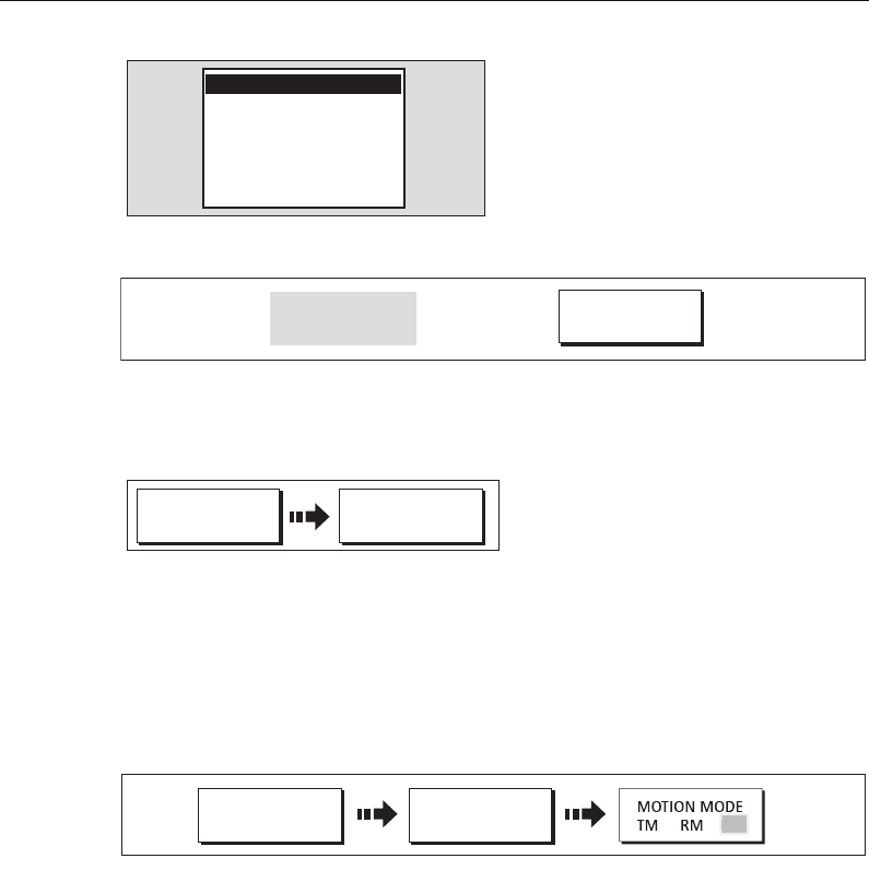
58 C-Series Display Reference Manual
To de-activate the arrival alarm
Stop navigating to your target waypoint
To stop navigating towards the selected waypoint:
o
Maintaining a view of your navigation
By selecting Auto Range mode, your chart will automatically adjust the range to
maintain both your boat and the target waypoint on screen, using the largest scale
possible.
To select Auto Range mode:
Note:
For more detail, see Setting the motion mode on page 85.
D8325_2
NAVIGATION ALARM
Waypoint Arrival
D8326_1
ACKNOWLEDGE
Wait 10 seconds
Or
D8324_1
GOTO... STOP GOTO
PRESENTATION
D7509-2
CHART MODE AND
ORIENTATION
AR
81221_4.book Page 58 Tuesday, February 28, 2006 5:24 PM
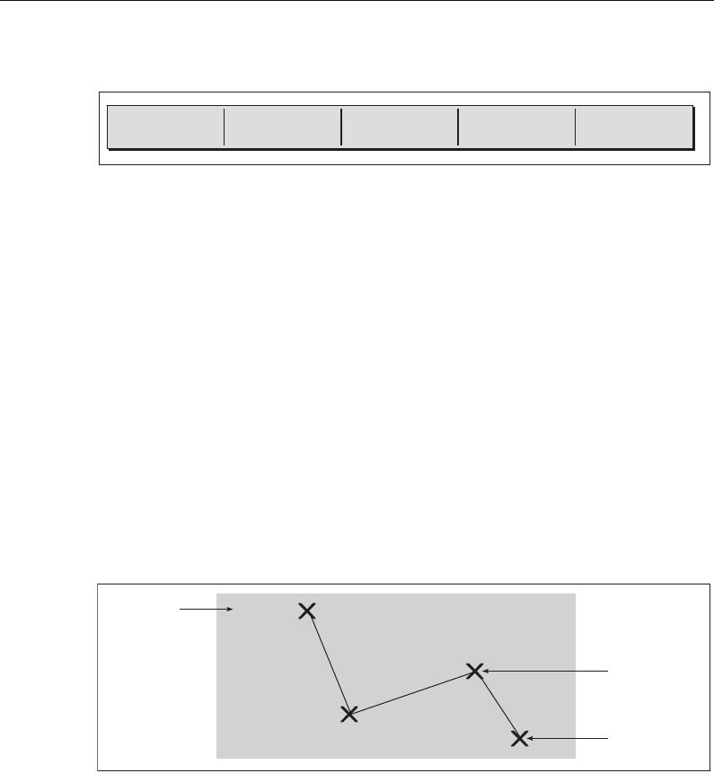
Chapter 4: Using the Chart 59
4.10 Building and following a route
This section describes how to use routes and includes the following:
• What is a route?
• What can I do with a route?
• Building and saving a route.
• Following a route.
• Viewing details of routes.
Once created you have the option to view a route’s details, amend its course, edit its
name and color or erase it.
All route options can be accessed via the ROUTES soft key.
What is a route?
A route is a series of waypoints used to navigate a course. A route is displayed on
screen as a series of waypoints linked by a line.
What can I do with a route?
You can:
• Build a temporary route that you follow immediately (Quick Route). If you do not
rename a quick route, it will be overwritten and its waypoints deleted when a new
quick route is built.
• Build and save a route for later use, in which case the route is stored in the route list.
• Convert a track of your course into a route (see
page 80
).
SHOW/HIDE
ROUTES ...
FOLLOW ROUTE
OPTIONS ...
BUILD NEW
ROUTE ...
REVIEW AND EDIT
ROUTES ...
D6534-2
D8327_1
Sunday Trip
Waypoint
Route name
Route
destination
81221_4.book Page 59 Tuesday, February 28, 2006 5:24 PM
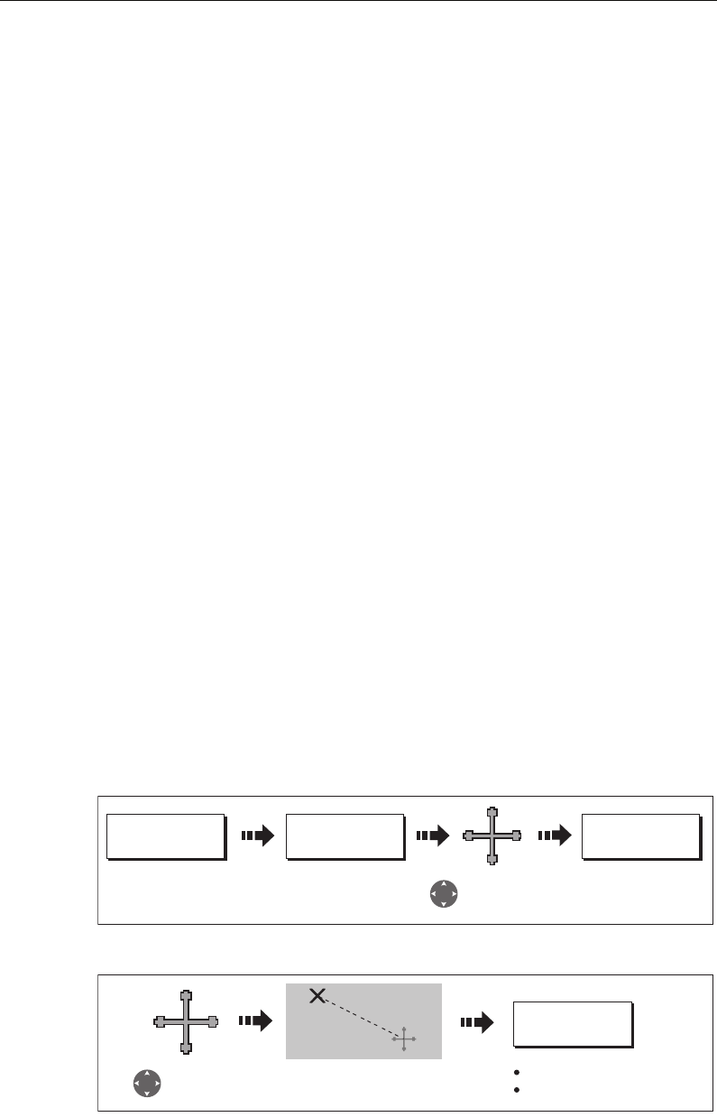
60 C-Series Display Reference Manual
Building a route
Routes can either be built on screen or via the waypoint list. A route consists of:
• New waypoints that you have specifically placed for that route
Or
:
• Existing waypoints that are already stored in the system
Or:
• A combination of new and existing waypoints.
Note:
A route can also be created from a track. See page 80 for details.
Up to 100 routes can be added to your system, each consisting of up to 50 waypoints.
As each waypoint is added, it is assigned an index number corresponding to its
position in the route and drawn on the chart using the currently specified symbol.
The following should be noted:
• When a route is being built it is not active and does not affect any current naviga-
tion.
• You can include a waypoint more than once in a route, but the same waypoint can-
not be placed consecutively.
• You can create a new route when the route list is full but on saving this, you will be
prompted to choose an existing route to overwrite.
• You cannot save a new route if any of the waypoints within it are currently active.
• The way in which the OK and CANCEL buttons operate is different when you are
building and editing routes (see below).
Building a route on screen
You can build a route on screen that consists of either new or existing waypoints or a
combination of both.
... using new waypoints
1. To place the first waypoint in a route:
2. To place subsequent waypoints in the route:
ROUTES
D8343_1
PLACE WAYPOINT
BUILD NEW
ROUTE
Position cursor
at required
position
To place new way-
point at cursor's
position
D8344_1
PLACE WAYPOINT
Move cursor to
next waypoint
position
Next waypoint placed
Dashed line now solid
Cursor joined to waypoint
with dashed line.
Route 1
81221_4.book Page 60 Tuesday, February 28, 2006 5:24 PM
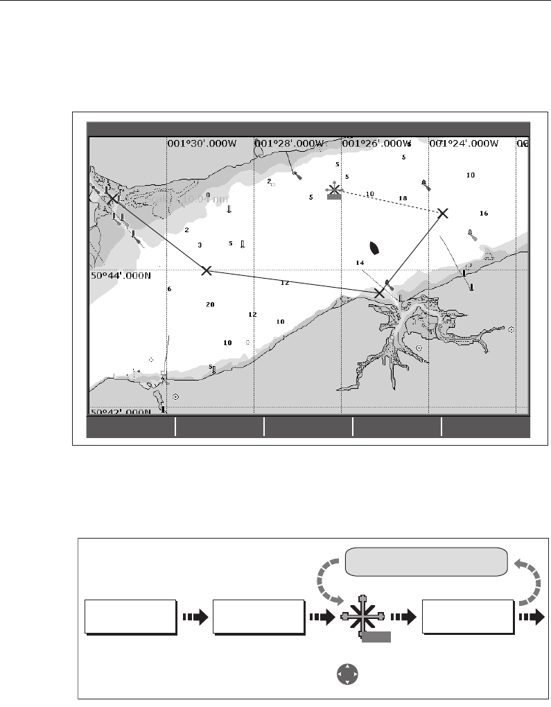
Chapter 4: Using the Chart 61
3. Continue entering waypoints. If you make an error, you can remove the last way-
point (see
page 62
for details).
4. Save your route when it is complete (see
page 63
for details).
... using existing waypoints
You can use waypoints that already exist, to build a new route.
1. Create your route:
Note:
If you make an error, you can remove the last waypoint (see page 62 for details).
2. Save your route when it is complete (see
page 63
for details).
Building a route using the waypoint list
You may prefer to build routes using existing waypoints in the waypoint list:
1. Select the Waypoint List route build option:
Sunday Trip#
GULLY RIDGE
Sunday Trip#
PORT POINT
Sunday Trip#
CREEK VIEW
CREEK POINT
PORTSIDE
Port point
Portside
D6546_2
RTE
SHOW/HIDE
ROUTES…
FOLLOW ROUTE
OPTIONS…
BUILD NEW
ROUTE
REVIEW AND EDIT
ROUTES…
4nm North-Up (Relative Motion) Local
D8351_1
Move cursor
over required
waypoint.
Includes waypoint in
route
ROUTES BUILD NEW
ROUTE
USE THIS
WAYPOINT
Repeat as necessary
WPT
81221_4.book Page 61 Tuesday, February 28, 2006 5:24 PM
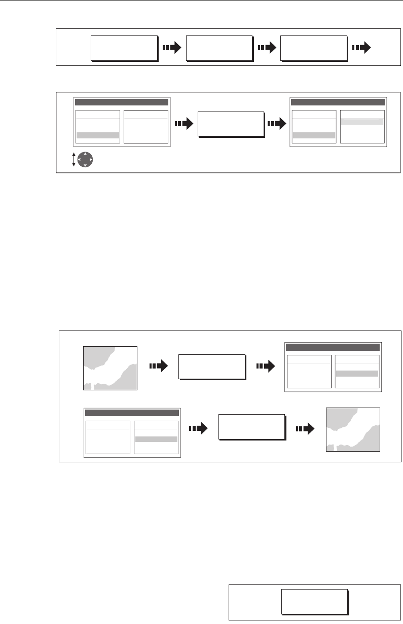
62 C-Series Display Reference Manual
2. Select and insert the first waypoint in the new route:
3. Continue entering waypoints until your route is complete.
Note:
If you make an error, you can delete the waypoint from the new route list (for
details see page 63).
Building a route on-screen and via the waypoint list
You can build your route using both the on-screen and the waypoint list methods
described on the previous pages. This will necessitate alternating control between the
Make Route dialog and the chart.
Changing control
Making changes to the route being built
If you make an error whilst building a route you can:
• Undo the last waypoint (on-screen route build only).
• Delete a waypoint from the new route list (waypoint list route build only).
• Abandon the route build.
Undoing the last waypoint
To remove the last waypoint when you
are building a route on-screen:
D6498-3
USE WAYPOINT
LIST
BUILD NEW
ROUTE
ROUTES...
D8355-1
INSERT
WAYPOINT
Highlight required
waypoint
Waypoint added to New Route.
Make Route
New Route Waypoints
Crag Rock
Blyth Bay
yy
Waypoints
Crag Rock
Blyth Bay
Sandy Bay
Make Route
S
an
dy
Ba
y
New Route
0
1 San
d
y Bay
D8357-1
USE WAYPOINT
LIST...
USE CURSOR.....
Chart to Make Route dialog
Make Route
New Route
01 Sandy Bay
02 Crag Rock
03 Rush Creek
Waypoints
Crag Rock
Blyth Bay
Sandy Bay
Make Route dialog to chart
Make Route
New Route
01 Sandy Bay
02 Crag Rock
03 Rush Creek
Waypoints
Crag Rock
Blyth Bay
Sandy Bay
D8352_1
UNDO WAYPOINT
81221_4.book Page 62 Tuesday, February 28, 2006 5:24 PM
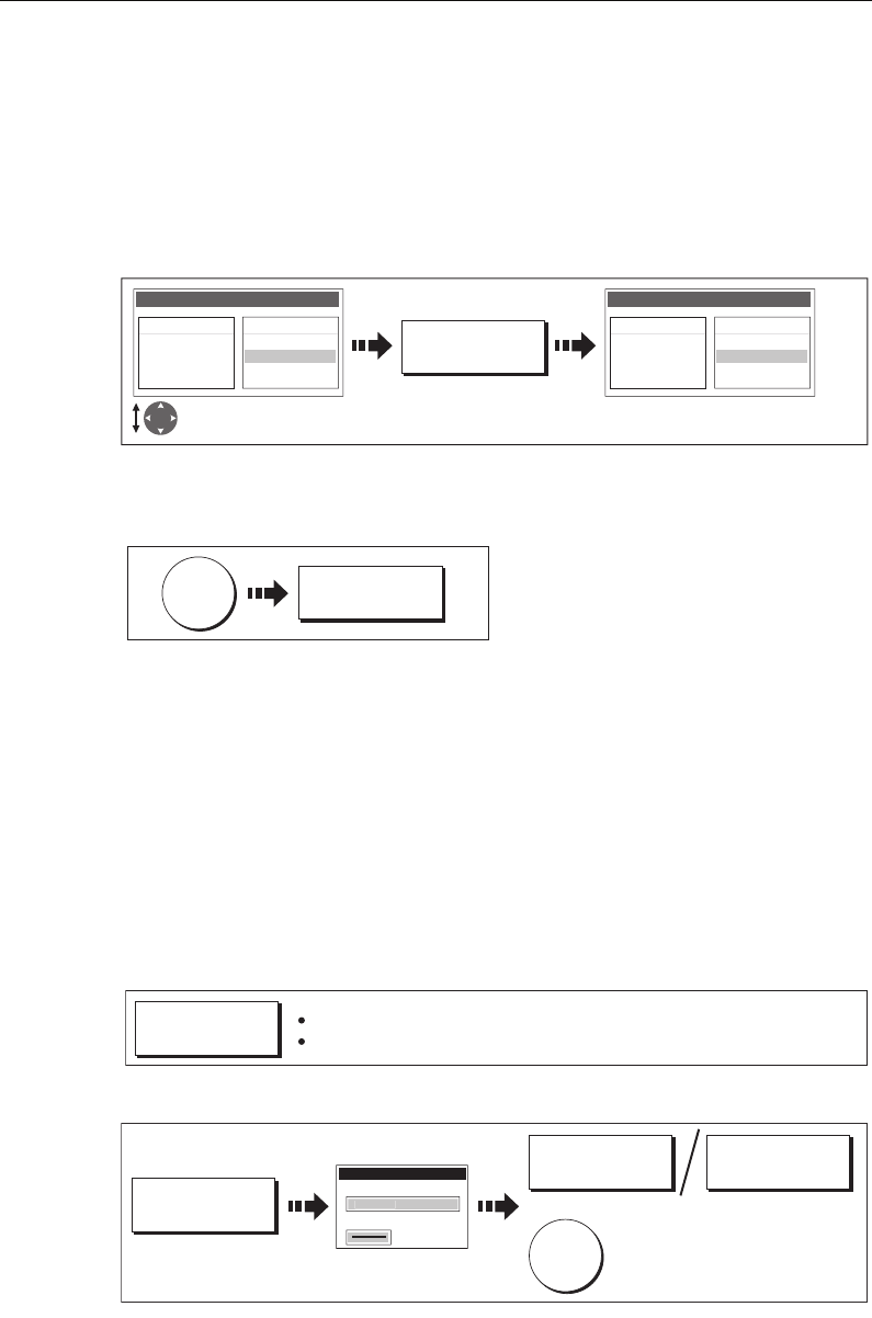
Chapter 4: Using the Chart 63
The waypoint and its dotted line are removed from the screen and the cursor moves
back to the previous waypoint. If you repeatedly press these keys, successive
waypoints are removed.
Delete a waypoint from the new route list
If you insert a waypoint incorrectly into a route that you are building via the waypoint
list, you can remove it:
To abandon the route build
To cancel the route that you are currently building (on-screen or via the waypoint list):
Saving routes
Once you have built your route either on screen and/or via the waypoint list you have
the option to either:
• Save and immediately follow the built route (Quick Route)
Or:
• Save the built route for later use (and rename it if required).
Quick routes
A route that is saved and immediately followed is referred to as a Quick Route. If a
Quick Route already exists, it is overwritten unless you rename it (see
page 82
).
To save the built route for later use
o
Note:
For further details on editing a dialog box, please refer to page 11
D8356-1
REMOVE
WAYPOINT
Highlight incorrect
waypoint Remaining waypoints close-up
and renumber accordingly
Make Route
New Route
01 Sandy Bay
02 Crag Rock
03 Rush Creek
Waypoints
Crag Rock
Blyth Bay
Sandy Bay
Make Route
New Route
01 Sandy Bay
02 Rush Creek
Waypoints
Crag Rock
Blyth Bay
Sandy Bay
D8353_1
CANCEL
YES
D8348-1
FOLLOW (QUICK)
ROUTE
Route saved under 'Quick Route'
Follow route commences
D8350_1
SAVE ROUTE...
EDIT NAME EDIT COLOR
To accept default
Save Route
R
ou
te
1
Name
Color
OK
Or:
81221_4.book Page 63 Tuesday, February 28, 2006 5:24 PM
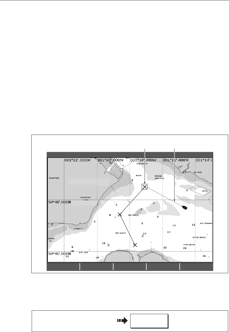
64 C-Series Display Reference Manual
Following a route
When you are following a route the active route is shown on all chart windows. When
the distance to the next waypoint in the route is less than that specified for the arrival
alarm radius (see
page 188
), or your boat reaches the closest point of approach to the
target (defined by a line passing through the waypoint and perpendicular to the route
leg), a warning dialog is displayed and an alarm sounds (see
page 57
). Once the alarm
is acknowledged the next waypoint is selected, the display updates to indicate the
next leg of the route and the system sends the new navigation data to the autopilot.
There are several ways to select the follow route option:
• Using Quick Route.
• Using the cursor.
• Via the route list.
• In reverse order.
Note:
You can stop following an active route at any time by pressing
STOP FOLLOW
.
Follow using Quick Route
This option follows a route as soon as it is built. For more details see
page 60
.
NORTH POINT
KNOLL
COWES
4nm North-Up (Relative Motion) Local
D6606-2
ADVANCE
WAYPOINT STOP FOLLOW RESTART XTE
Target waypoint
highlighted
Course to active
waypoint
D6542-2
Build your route
FOLLOW (QUICK)
ROUTE
81221_4.book Page 64 Tuesday, February 28, 2006 5:24 PM
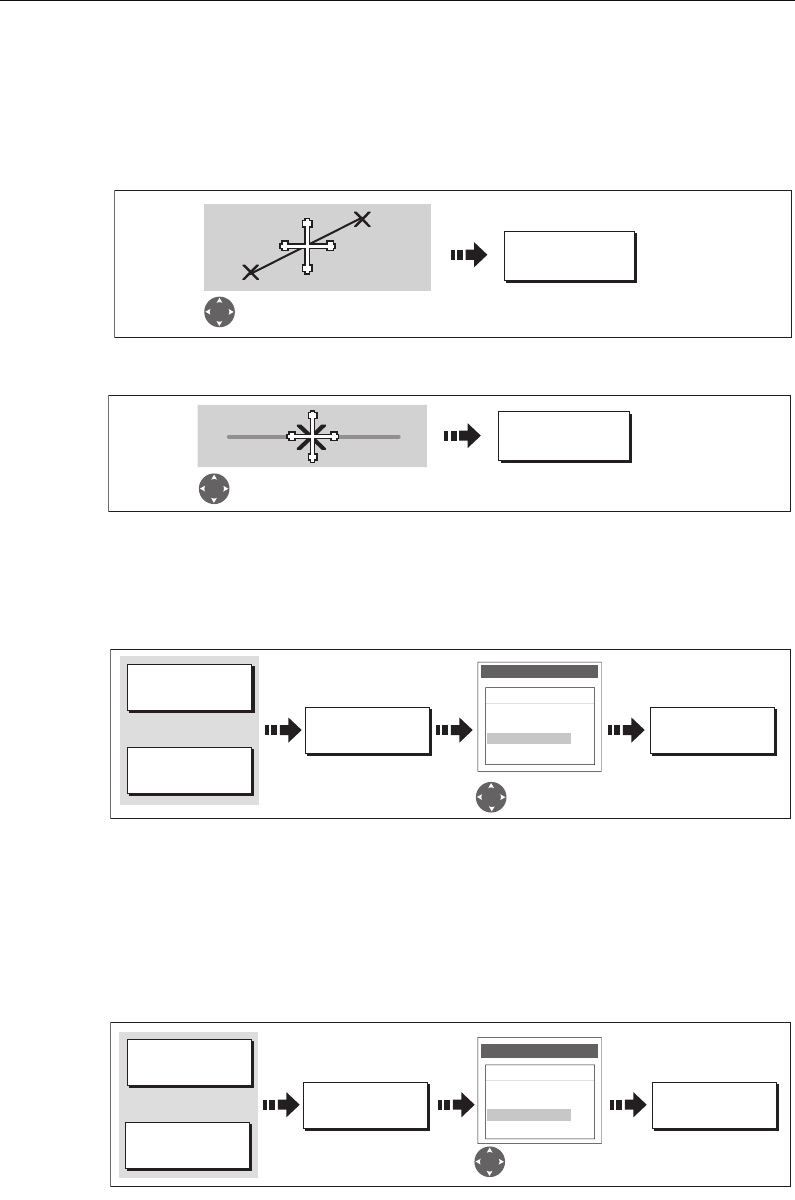
Chapter 4: Using the Chart 65
Follow using the cursor
You can either use the cursor to select and follow a route from the start of the route or
from a selected waypoint within the route.
... from the start of the route
... from a selected waypoint within the route
Follow using the route list
This option directs you to the start of the route that you have selected on the route list
and then follows it:
Follow in reverse order
This option reverses the waypoint order (i.e. the last waypoint of the original route is
now the first) and renumbers the waypoints accordingly. The route name moves to the
reassigned first waypoint and then the system automatically activates the reverse-
follow route function.
Note:
To stop following an active route at any time, press
STOP FOLLOW
.
FOLLOW THIS
ROUTE
D7510-2
Position cursor over any
leg of required route
FOLLOW FROM
HERE
D6717-3
Position cursor over
appropriate waypoint
D6539-4
FOLLOW ROUTE
OPTIONS... FOLLOW ROUTE
ROUTES...
GOTO...
Or:
Route List
Color Name
---- Quick Route
---- Route 1
---- Route 2
---- Route 3
Select route to
follow
To start follow route
D8362_1
FOLLOW ROUTE
OPTIONS...
REVERSE AND
FOLLOW
ROUTES...
GOTO...
Or:
Route List
Color Name
---- Quick Route
---- Route 1
---- Route 2
---- Route 3
Select required
route
Reverse-follow
route starts
81221_4.book Page 65 Tuesday, February 28, 2006 5:24 PM
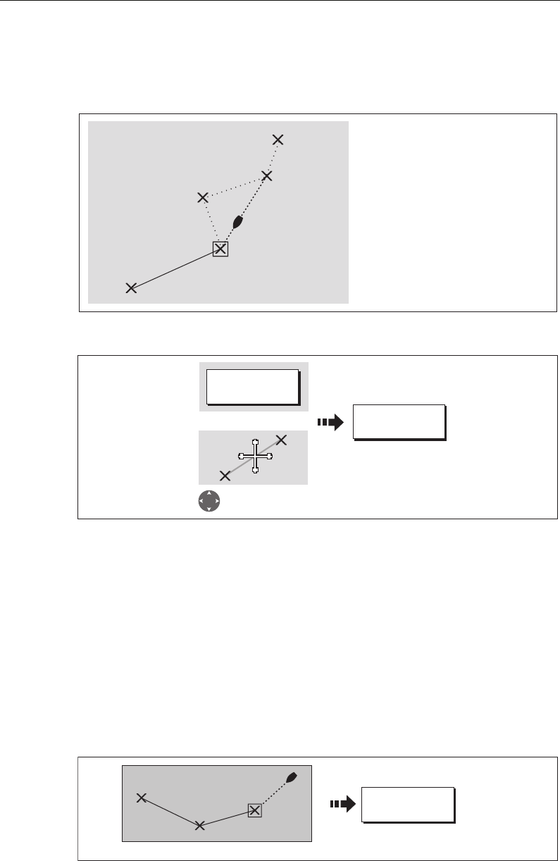
66 C-Series Display Reference Manual
Advance to the next waypoint in a route
If you are following a route, you have the option to advance to the next waypoint in
that route.
To advance to the next waypoint in a route:
Note:
If the current destination is the last waypoint, then it advances on to the first
waypoint in the route.
Resetting cross track error (XTE)
When you are following a route or going to a waypoint, you can restart the XTE. This
results in a new course from the current vessel position to the current target waypoint.
Restarting XTE is useful if you find yourself off track and want to go straight to your
target, rather than get back onto the original track.
Although RESTART XTE causes your vessel to change course, it does not affect the
saved route.
D6603_3
2
3
4
W.Wight
1
W.Wight
5
Example:
In this example, the advance
waypoint option was selected
following arrival at Waypoint 2.
This has resulted in Waypoint 3
being dismissed and the course of
the route advancing to Waypoint 4.
D6499-4
ADVANCE
WAYPOINT
GOTO…
Position cursor over route
Or
D6549_3
When you are following a route ..
RESTART XTE
81221_4.book Page 66 Tuesday, February 28, 2006 5:24 PM
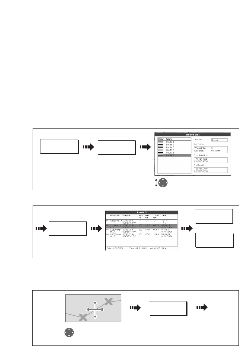
Chapter 4: Using the Chart 67
Viewing details of routes
Details of all routes that you create are held in the Route List. You can:
• View the route list and then select the required route, or
• Select the required route on-screen.
The TIME and SOG options can then be used to aid passage planning by displaying the
time in hours or as an ETA and the SOG as actual or planned.
If the route is currently being navigated to (active), the data is updated to show
bearing, distance and time from your current position.
... via the route list
1. Display the Route List:
2. Display details of the selected route:
... with the cursor
1. Select the route and the REVIEW AND EDIT THIS ROUTE option:
2. Display details of the selected route:
REVIEW AND EDIT
ROUTES…
D8997_1
ROUTES…
Select required route. Details
displayed on right of screen.
D8998_1
Toggle as required
and/or
ROUTE DETAILS...
TIME
ETA HOURS
SOG
ACTUAL PLANNED
REVIEW AND EDIT
THIS ROUTE
D9000_1
Position cursor over
any leg of the required
route
81221_4.book Page 67 Tuesday, February 28, 2006 5:24 PM
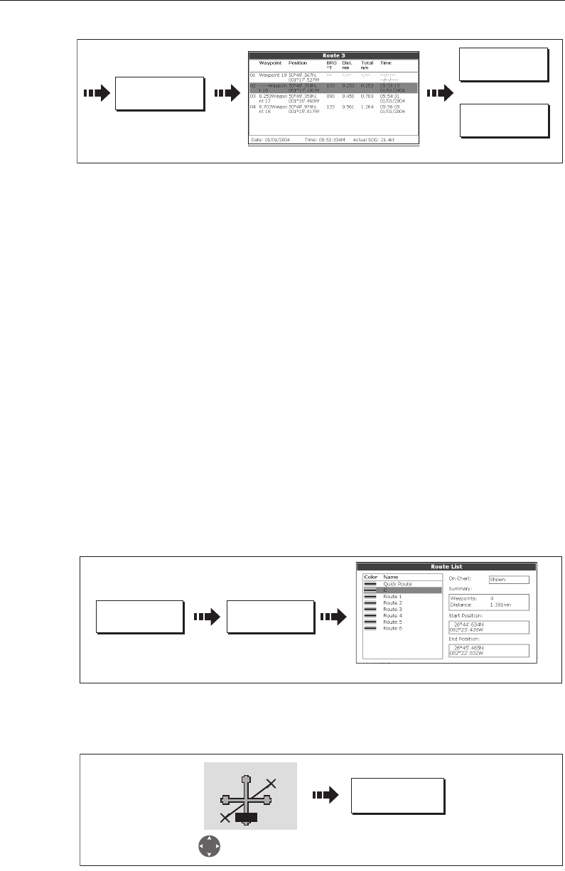
68 C-Series Display Reference Manual
4.11 Editing routes
Once you have created a route, it can be edited in a variety of ways. You can:
• Reverse a route (see
page 65
)
• Amend the course of a route (see
page 69
).
• Change the name of a route (see
page 73
).
• Change the color of a route (see
page 73
).
• Erase a route (see
page 73
).
Note:
An active route can be edited, with the exception of the target waypoint. If a
waypoint being edited becomes the target, then the system shall cancel the edit; the
waypoint shall remain in its original position.
Selecting a route for editing
For a route to be edited it must first be selected either via the route list or by selecting
the appropriate route on-screen.
... via the route list
You can now edit the route as described on
page 69
.
... with the cursor
You can now edit the route as described on
page 69
.
D8998_1
Toggle as required
and/or
ROUTE DETAILS...
TIME
ETA HOURS
SOG
ACTUAL PLANNED
ROUTES ... REVIEW AND
EDIT ROUTES ...
Highlight required route
D8369_1
D8370_1
REVIEW AND EDIT
THIS ROUTE
Route 3
Move cursor over
required route
RTE
81221_4.book Page 68 Tuesday, February 28, 2006 5:24 PM
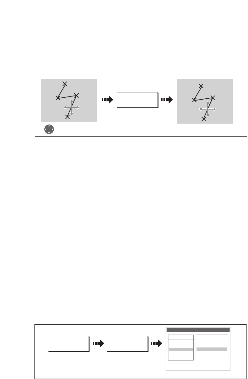
Chapter 4: Using the Chart 69
Editing the selected route
Once you have selected the appropriate route (see previous section) you can proceed
to edit it.
Reversing a route
You can reverse the course of a route:
Note:
For details of how to reverse and immediately follow a route, see page 65.
Changing the course of a route
You can amend the course of a route by:
• Adding a waypoint to the beginning or end of the route or between two existing
waypoints.
• Moving a waypoint within a route.
• Removing a waypoint.
You can effect these changes either via the Make Route dialog box or by selecting the
route on screen and then using the appropriate soft keys (not applicable when adding
a waypoint at the beginning of a route).
Note:
You will not be able to edit the waypoint that you are currently navigating to
(target waypoint).
Add a waypoint at the beginning of a route
This option changes the course of a route by adding an existing waypoint to the start of
the route:
1. Select the appropriate route for editing (see
page 68
).
2. Display the Make Route screen:
REVERSE ROUTE
D6541-4
Select appropriate
route with cursor Waypoints renumber
and route name moves
BayView
1
2
3
4BayView
1
23
4
D6507_3
USE WAYPOINT
LIST...
AMEND ROUTE
COURSE…
The Make Route screen is displayed
Make Route
Waypoints
Harbour Ent.
Midchannel
Outer Harbour
Pierhead
Waypoint 4
50016'.75N
00106'.095W
50047'.356N
00106'.604W
Sunday tour
01 Midchannel
02 Outer Harbour
03 Harbour Ent.
81221_4.book Page 69 Tuesday, February 28, 2006 5:24 PM
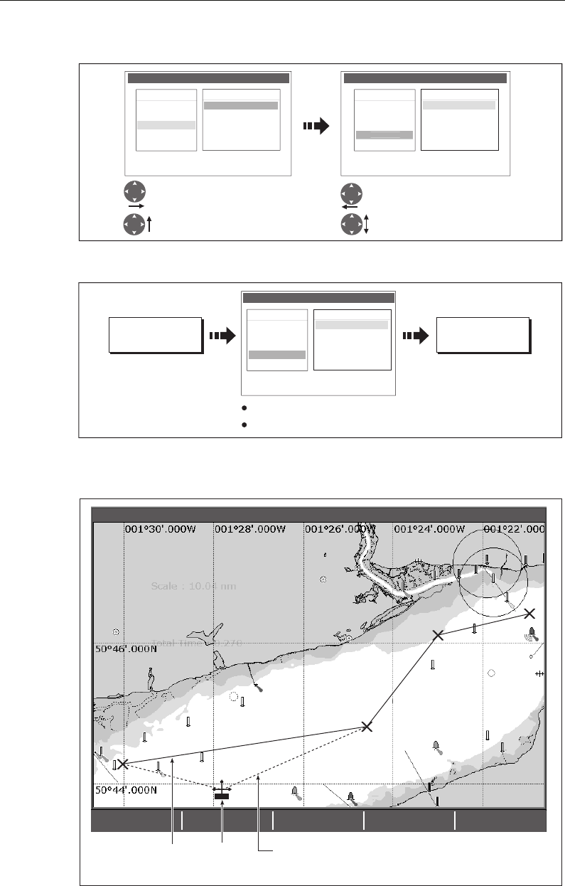
70 C-Series Display Reference Manual
3. Select the start of the route and the waypoint for insertion:
4. Insert waypoint and save route:
Add a waypoint within a route
This option inserts a waypoint within a route in order to change its course e.g.
D8371_1
Move control to route column.
Make Route
Waypoints
Harbour Ent.
Midchannel
Outer Harbour
Pierhead
Waypoint 4
50016'.75N
00106'.095W
50047'.356N
00106'.604W
Sunday tour
01 Midchannel
02 Outer Harbour
03 Harbour Ent.
Return control to Waypoint
column.
Select waypoint for insertion.
Make Route
Waypoints
Harbour Ent.
Midchannel
Outer Harbour
Waypoint 4
50016'.75N
00106'.095W
50047'.356N
00106'.604W
P
ierhea
d
Sunday tour
01 Midchannel
02 Outer Harbour
03 Harbour Ent.
Move highlight above first
waypoint in route.
D8372_1
Waypoint insert at beginning of route.
Route index renumbers.
Make Route
Waypoints
Harbour Ent.
Midchannel
Outer Harbour
Waypoint 4
50016'.75N
00106'.095W
50047'.356N
00106'.604W
Pier
h
e
ad
Sunday tour
01 Pierhead
02 Midchannel
03 Outer Harbour
04 Harbour Ent.
INSERT
WAYPOINT SAVE ROUTE...
D6604_2
RTE
PLACE WAYPOINT
4nm North-Up (Relative Motion) Local
Original
course
Position
for new
waypoint
Amended
route
81221_4.book Page 70 Tuesday, February 28, 2006 5:24 PM
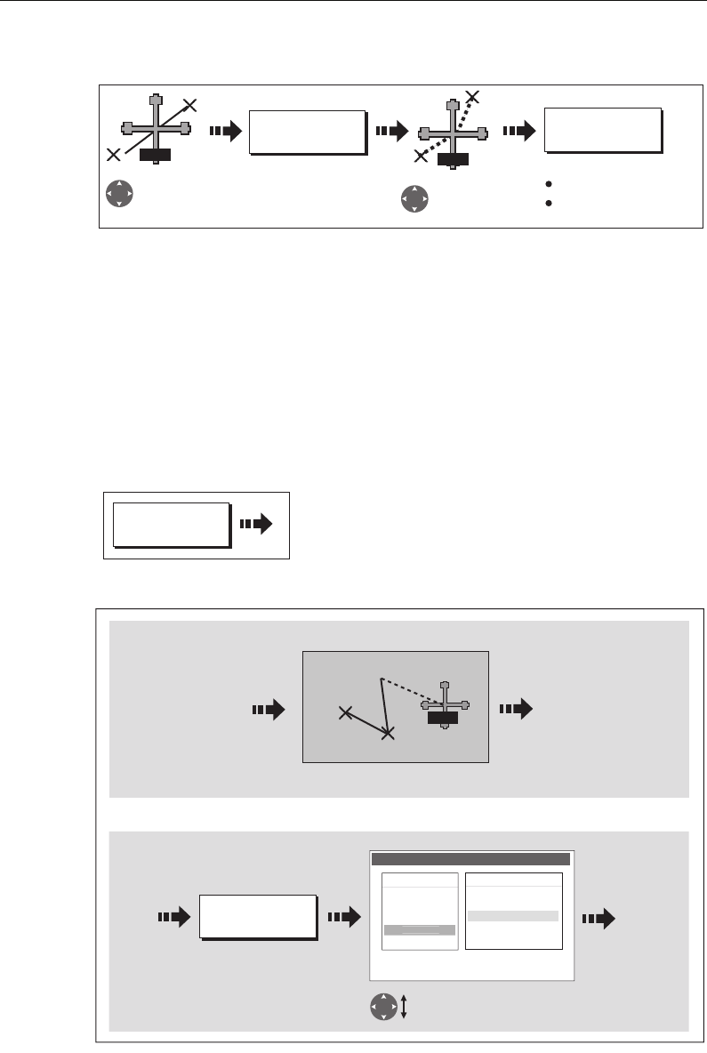
Chapter 4: Using the Chart 71
To add a waypoint within a route:
Note:
You can also use the method described on page 69, to add a waypoint within a
route.
Add a waypoint(s) to the end of a route
This option inserts a waypoint (or series of waypoints) at the end of a route in order to
extend its existing course. You can create new waypoints for this purpose and/or use a
waypoint that already exists in the system.
1. Select the appropriate route for editing (see
page 68
).
2. Select the amend route course option:
3. Define new or existing waypoint:
D8373_1
INSERT
WAYPOINT
PLACE
WAYPOINT
Move cursor
over appropriate
leg of route
Stretch to
position for
new waypoint
Route course changes
Route index re-
numbers
RTE RTE
D8382_1
AMEND ROUTE
COURSE...
D8380_1
USE WAYPOINT
LIST...
Or:
Define new waypoint
Use existing waypoint
Select waypoint for insertion.
Make Route
Waypoints
Harbour Ent.
Midchannel
Outer Harbour
Waypoint 4
50016'.75N
00106'.095W
50047'.356N
00106'.604W
P
ierhea
d
Sunday tour
01 Midchannel
02 Outer Harbour
03 Harbour Ent.
Drag cursor to required position for
additional waypoint
1
2
3
RTE
81221_4.book Page 71 Tuesday, February 28, 2006 5:24 PM
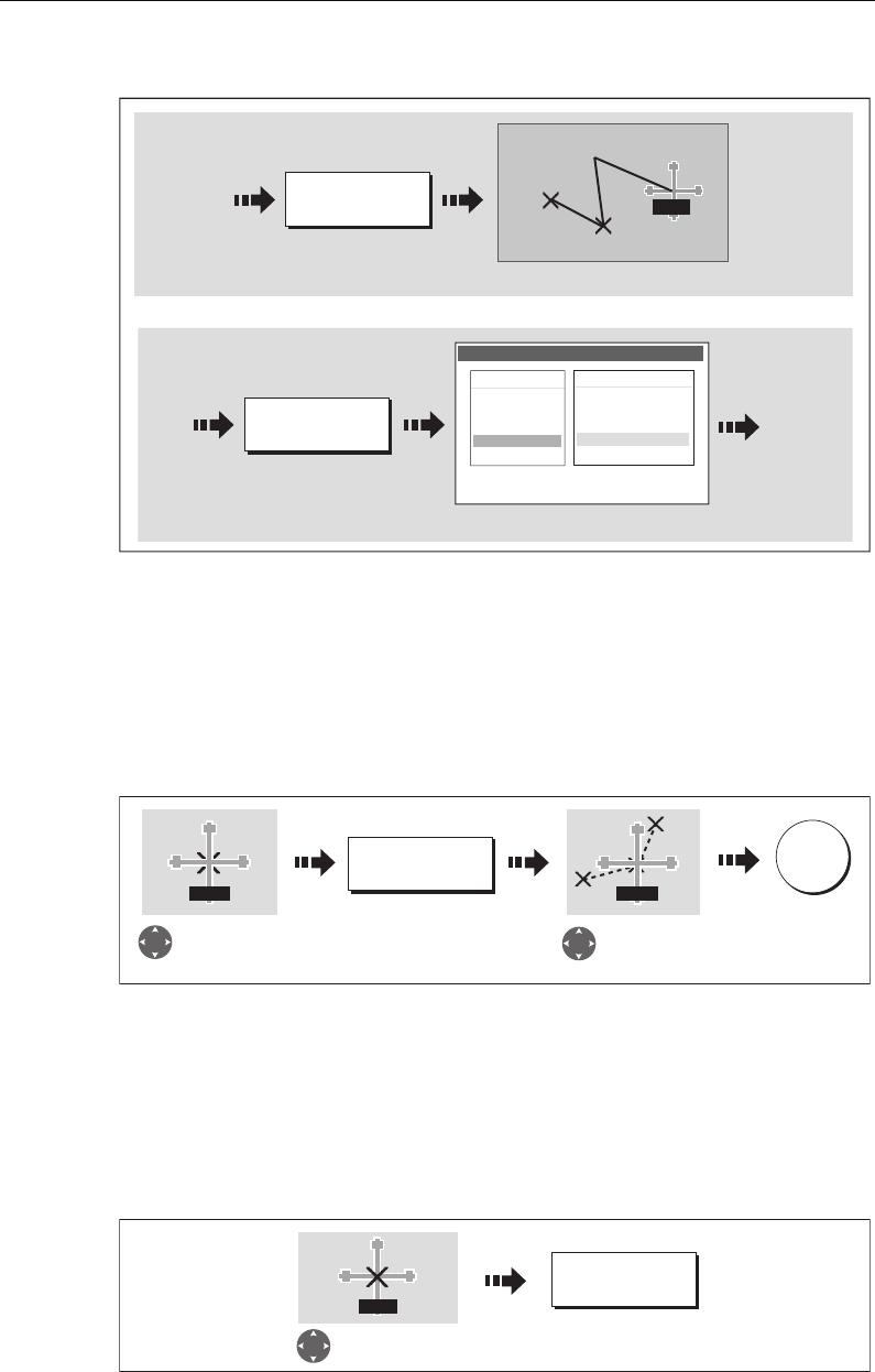
72 C-Series Display Reference Manual
4. Select waypoint to be added:
5. If required, you can add further waypoints to the end of the route by repeating
steps (3) and (4) above.
Note:
If you wish to add a combination of existing and new waypoints to the end of a
route, you will need to move control from/to the on-screen cursor/Make Route screen
(see page 62).
Move a waypoint within a route
Note:
A waypoint’s new position will be reflected in all other routes that make use of
it.
Remove a waypoint from within a route
You can remove a waypoint from within a route provided that it has not been used in
another route. If you try to remove a waypoint that is used in another route, the system
will warn you that it cannot be removed.
D8381_1
PLACE WAYPOINT
New leg added to end of route.
New leg added to end of route.
Or:
Add new waypoint at cursor
Sunday tour
01 Midchannel
02 Outer Harbour
03 Harbour Ent.
1
2
3
RTE
USE WAYPOINT
LIST...
Use existing waypoint Make Route
Waypoints
Harbour Ent.
Midchannel
Outer Harbour
Waypoint 4
50016'.75N
00106'.095W
50047'.356N
00106'.604W
Pierhea
d
D8374_1
MOVE WAYPOINT
Move cursor over
waypoint to be
repositioned
Drag cursor to
new position
OK
WPT WPT
D8374_1
REMOVE
WAYPOINT
WPT
Move cursor over
waypoint to be removed
81221_4.book Page 72 Tuesday, February 28, 2006 5:24 PM
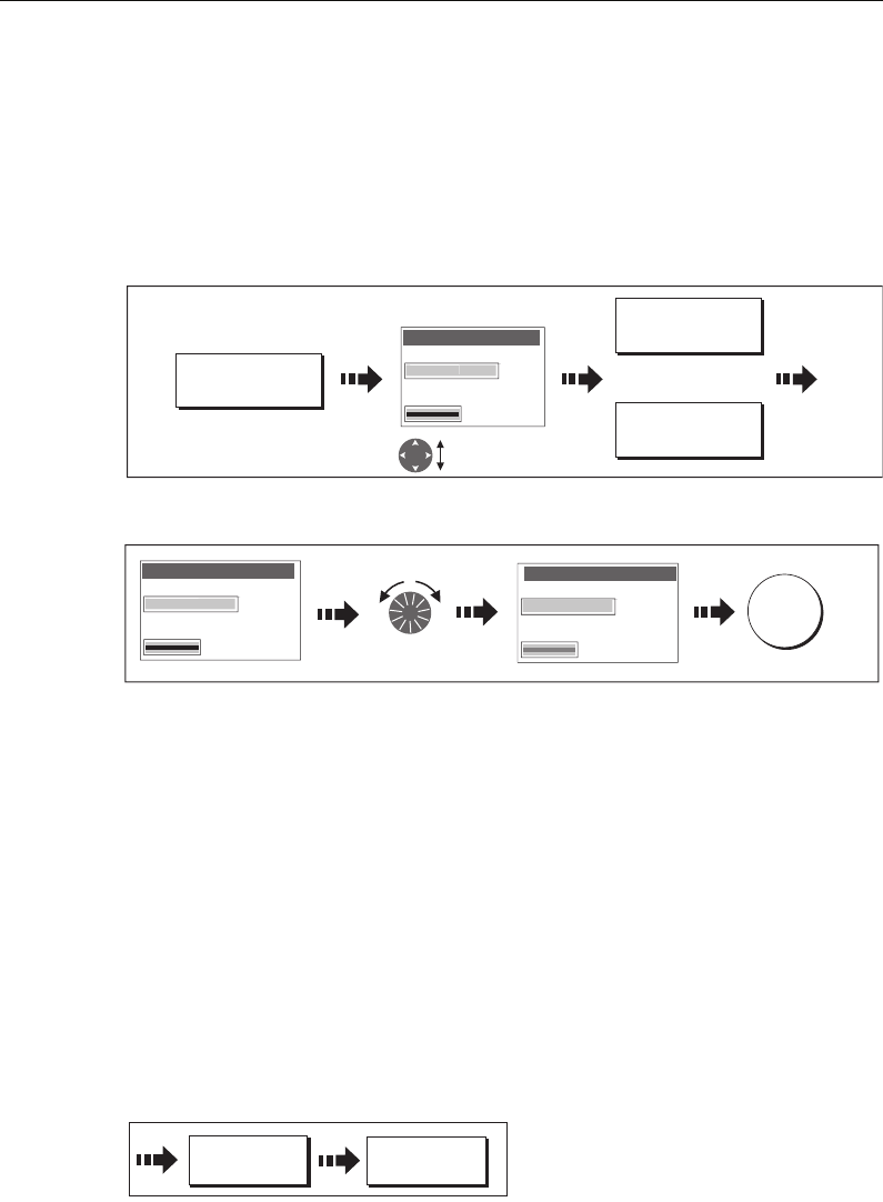
Chapter 4: Using the Chart 73
Changing the name or color of a route
You can change the name of a route from the default to a more meaningful one and/or
change the color if required. This will make them easier to distinguish from one
another, particularly if you have numerous routes in your system.
1. Select the appropriate route for editing (see
page 68
).
2. Select the Edit Name or Edit Color option:
3. Edit and save:
Note:
If the route has been saved by pressing
FOLLOW (QUICK) ROUTE
, the route is
named ‘Quick Route’. Changing its name prevents it being overwritten by a new Quick
Route.
Erasing a route
You can delete any route in your system except for the one that you are following.
When you erase a route the system deletes only those waypoints created with this
particular route. Waypoints that have been created separately or are used in other
routes are not deleted.
To erase a route:
1. Select the appropriate route for editing (see
page 68
).
2. Erase the track or route:
You can also erase all or selected routes, using the ARCHIVE & TRANSFER function as
described on
page 19
.
EDIT NAME AND
COLOR...
D8376_1
Select name
or color
Edit Route
Name
Rt1
Color
Rout
e
1
EDIT NAME
EDIT COLOR
Or
D8377_1
Edit Route
Name
Color
Da
rtm
ou
t
h
Edit color/name Save
OK
Edit Route
Name
Rt1
Color
R
ou
t
e
1
D8379-1
ERASE ROUTE YES
81221_4.book Page 73 Tuesday, February 28, 2006 5:24 PM
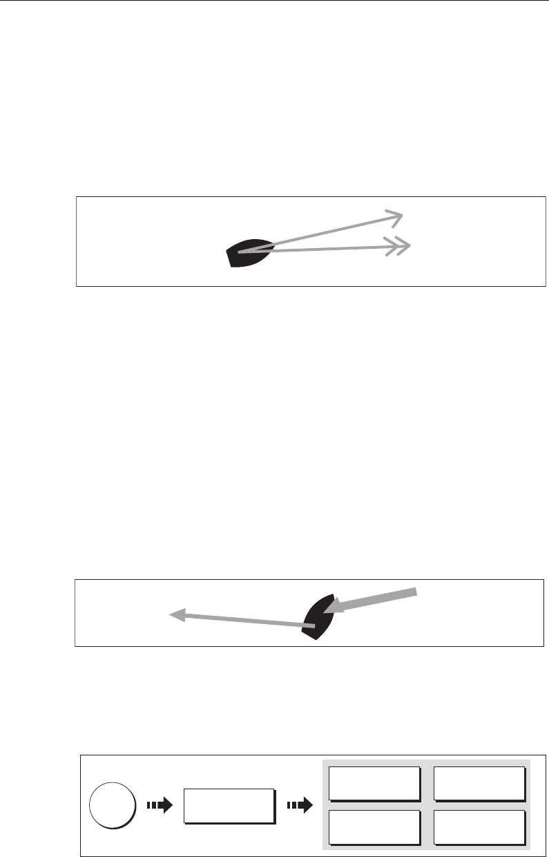
74 C-Series Display Reference Manual
4.12 Monitoring where you are going
... using chart vectors
You can display a variety of graphical indicators to help monitor where you are going:
Note:
Any vectors applied to a chart window that is set to system view, will be dis-
played in all other system view chart windows.
Heading (HDG) and course over ground (COG) vectors
The ship’s heading (HDG) is displayed as a line with an open arrow head. It does not
take account of winds or tides.
The course over ground (COG) indicates the boat’s actual course and is displayed as a
line with two open arrow heads.
The length of these lines is determined by the distance your boat will travel in the time
you have specified (3 mins, 6 mins or infinite) in the Chart Setup Menu (see
page 90
) at
the current speed.
Any times that you specify will apply to all chart views and if INFINITE is selected the
vector will extend to the edge of the chart window.
Note:
If neither the speed over ground (SOG) or heading are available, vectors cannot
be displayed.
Wind and tide arrows
Winds and tides are displayed as lines with solid arrow heads in the direction of the
wind or tidal set. Winds arrows point into your boat and tidal arrows point away. The
width of the arrow indicates its strength.
To switch graphical indicators on/off:
D6772-2
Heading vector
(HDG)
Course over ground
(COG)
D6773_2
Tide arrow
Wind arrow
DATA
D6548-2
CHART VECTORS
TIDE ARROW
ON OFF
WIND ARROW
ON OFF
HDG VECTOR
ON OFF
COG VECTOR
ON OFF
81221_4.book Page 74 Tuesday, February 28, 2006 5:24 PM
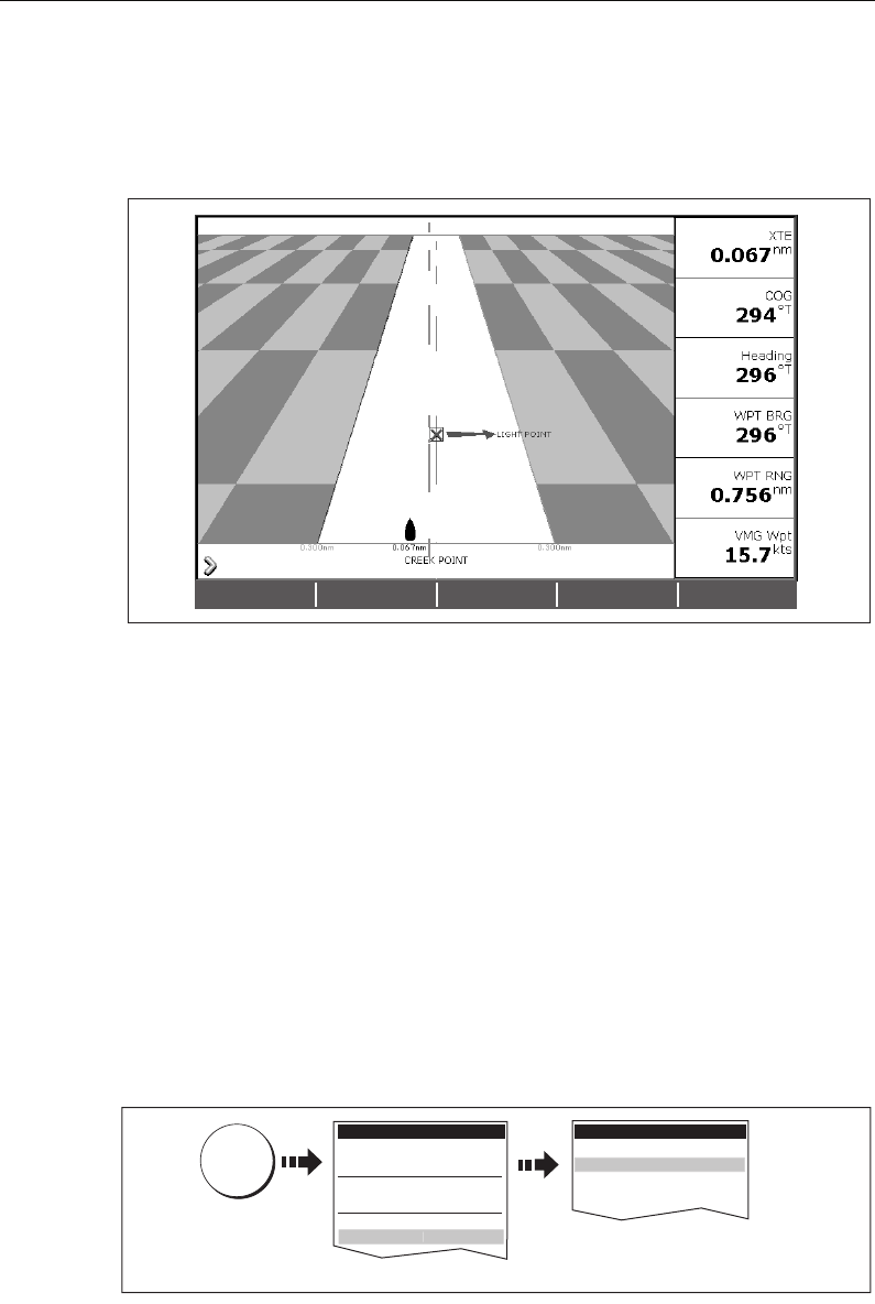
Chapter 4: Using the Chart 75
... using the Course Deviation Indicator (CDI)
The CDI assists with accurately maintaining your course to your destination. A ‘rolling
road’ in three dimensional perspective provides a real-time display of your boat’s
course. See
Chapter 8:Using the Course Deviation Indicator
for more information.
4.13 Warnings of potential dangers
When the appropriate equipment is installed and switched on, the following alarms
will be triggered when you are in the chart application:
• System alarms - Anchor, Timer, Alarm clock and Temperature.
• Navigation alarms - Arrival and Off track.
• Radar alarms - Guard zones.
•Fishfinder alarms.
• AIS alarms.
When an alarm is triggered, a buzzer sounds and a pop-up window describing the
alarm and how to clear it is displayed. In some cases, the appropriate action is taken by
the Chart. For example, following an arrival alarm, the next route leg is activated.
To switch these alarms on/off and set the limits:
Note:
For more details of alarms, see page 187.
D6895-2
D8363_1
MENU
Alarm Setup Menu
System Alarms Setup..
.
Radar Alarms Setup..
.
Fishfinder Alarms Setup...
Navi
g
ation Alarms Setup..
.
Select appropriate sub-menu
Select Alarm Setup
Setup
Chart Setup...
Cartography Setup
GPS Status...
Compass Setup...
System Setup...
Al
arm Setup..
.
81221_4.book Page 75 Tuesday, February 28, 2006 5:24 PM
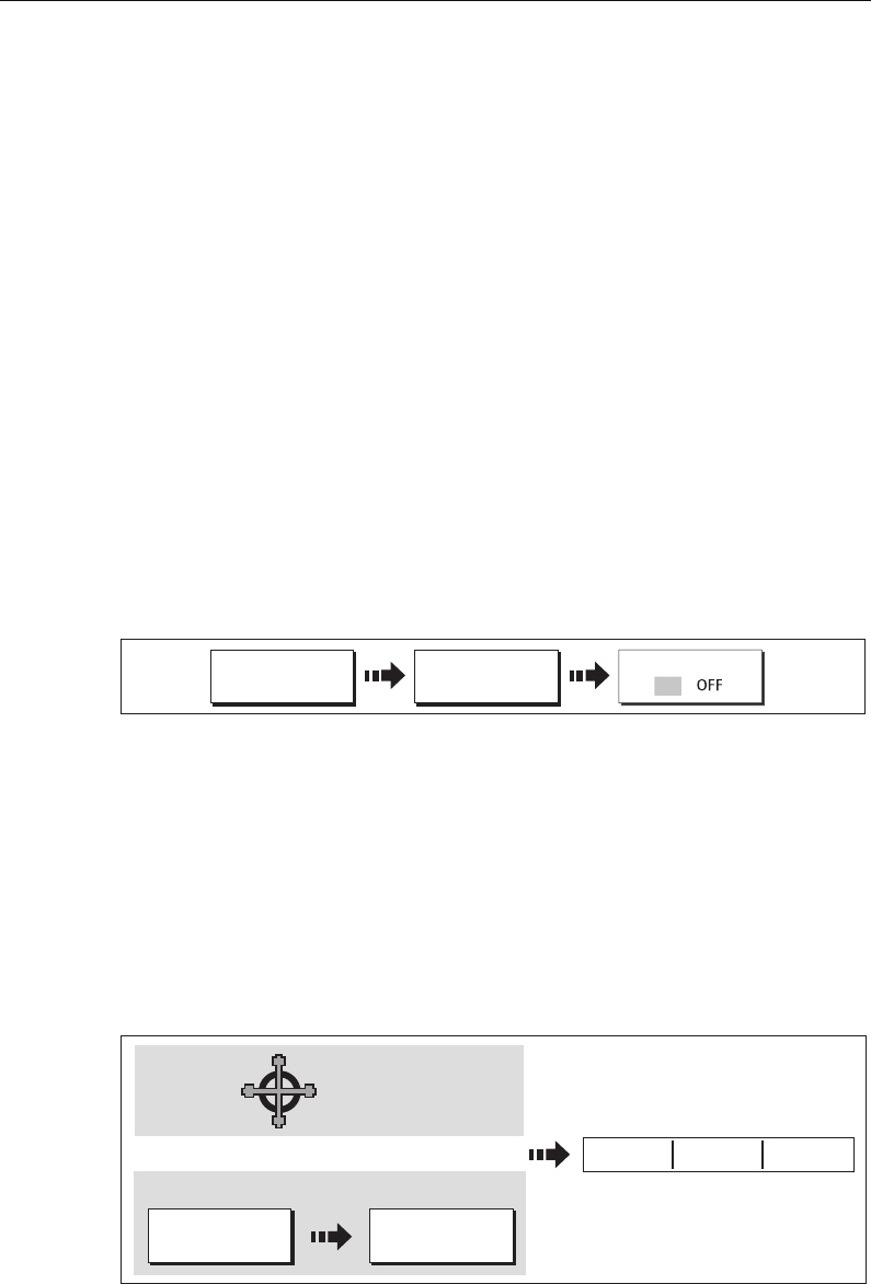
76 C-Series Display Reference Manual
4.14 Using the radar with the chart
You can enhance the use of your chart by combining it with the following radar
features:
• Radar range synchronization
•MARPA.
•Radar overlay.
Synchronizing the chart with radar range
When synchronization is switched on:
• The radar range in all radar windows, changes to match the chart scale.
• ‘Sync’ is indicated in the top left-hand corner of the chart window.
• If you change the radar range, in any radar window, all synchronized chart views
change scale to match.
• If you change the scale of a synchronized chart window, all radar windows change
range to match.
To set the radar range synchronization:
Note:
Radar range synchronization is not available when the chart motion mode is set
to Autorange.
Viewing MARPA targets on the chart
The Mini Automatic Radar Plotting Aid (MARPA) function is used for target tracking
and risk analysis. Although set up in radar mode or radar overlay, all MARPA targets
are displayed in the chart window and associated MARPA functions can be accessed
via the chart. For detailed information on MARPA see
page 143
.
To access the MARPA controls when you are in a chart application:
D9102_1
CHART MODE AND
ORIENTATION…
RADAR SYNC
PRESENTATION…
O
N
D6609-3
TARGET
TRACKING...
RADAR
OPTIONS...
Select the target
with cursor
On screen:
With radar overlay on:
ACQUIRE TARGET MARPA LIST... MARPA
OPTIONS...
Or:
Marpa controls displayed
81221_4.book Page 76 Tuesday, February 28, 2006 5:24 PM
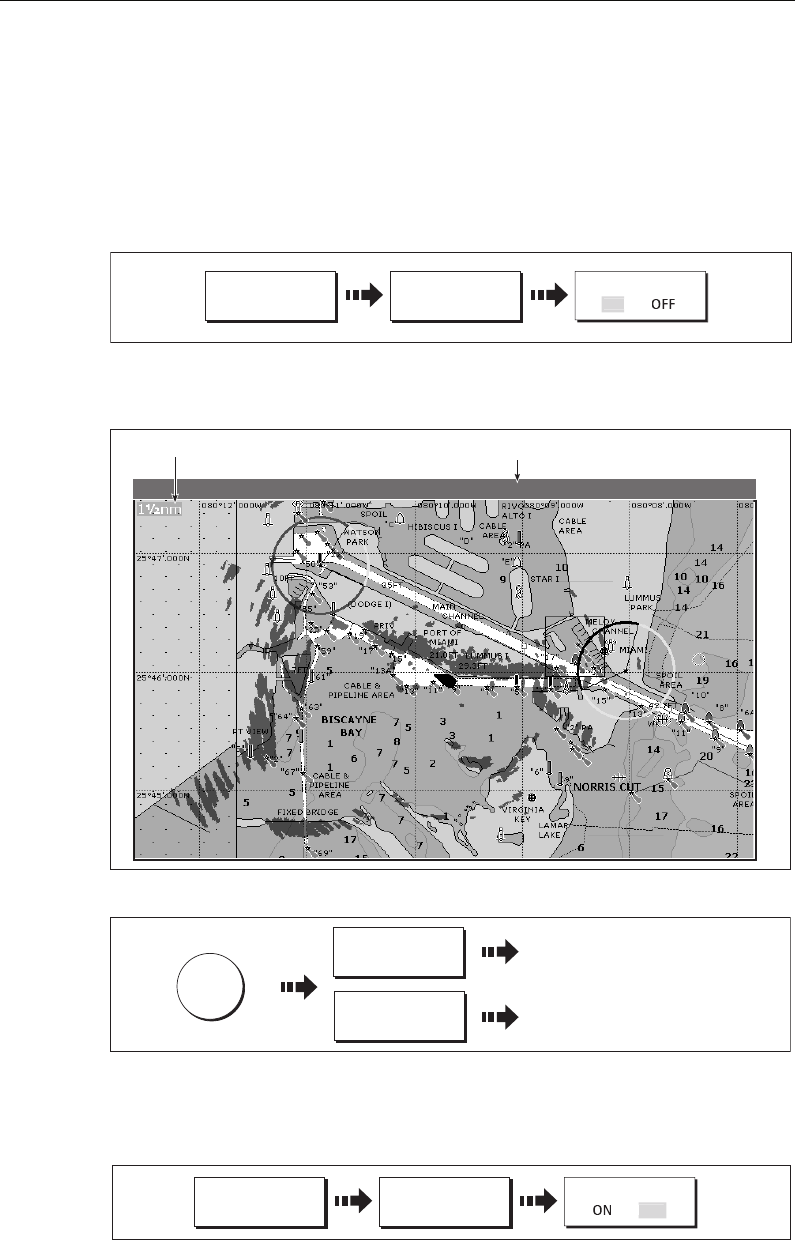
Chapter 4: Using the Chart 77
Distinguishing between fixed and moving objects
You can overlay radar image data over your chart image allowing better distinction
between fixed objects and other marine traffic. For best results, switch on Radar-Chart
synchronization (see
page 76
) to ensure radar range and chart scale are synchronized.
To switch radar overlay on:
1. Select radar overlay:
The default soft keys change to give access to some of the radar options and if a
radar is connected, the radar image will be overlaid on the chart e.g.
2. To access radar and navigation options:
Note:
If radar overlay is applied to a chart window that is set to system view, the over-
lay will be displayed in all other system view chart windows.
To turn off radar overlay:
PRESENTATION CHART LAYERS RADAR OVERLAY
D6889-4
O
N
Radar range
D6896-3
Status
4nm North-Up (Relative Motion) Local
Overlay
D8364_1
OK x2
NAVIGATION
OPTIONS...
RADAR
OPTIONS...
... For route and track options.
... For target tracking, gain and target
display or to change radar range.
PRESENTATION CHART LAYERS RADAR OVERLAY
O
F
F
D8365_1
81221_4.book Page 77 Tuesday, February 28, 2006 5:24 PM
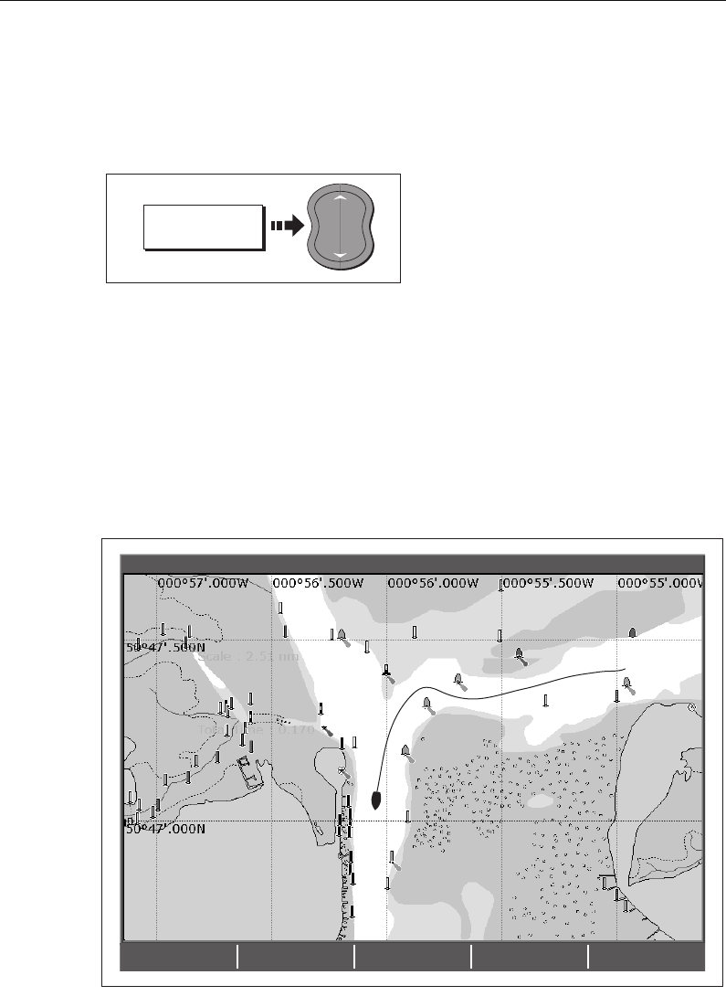
78 C-Series Display Reference Manual
Changing the radar range from the chart window
When the radar overlay is set to ON, the radar range is indicated in the top left-hand
corner of the chart window in the same color as the overlay. You can now change the
radar range:
Note:
If RDR RNG SYNC is set to ON (see page 76), the chart scale also changes
4.15 Recording where you have been
What is a track?
A track is an on-screen trail that represents the course you have taken. This trail is
made up of a series of track points which are created automatically. You can save the
track to create a permanent record of where you have been.
.
D7217-3
RADAR
OPTIONS...
D6585-1
RANGE
IN
OUT
D6607_2
FIND SHIP GOTO… ROUTES… TRACKS… PRESENTATION…
4nm North-Up (Relative Motion) Local
81221_4.book Page 78 Tuesday, February 28, 2006 5:24 PM
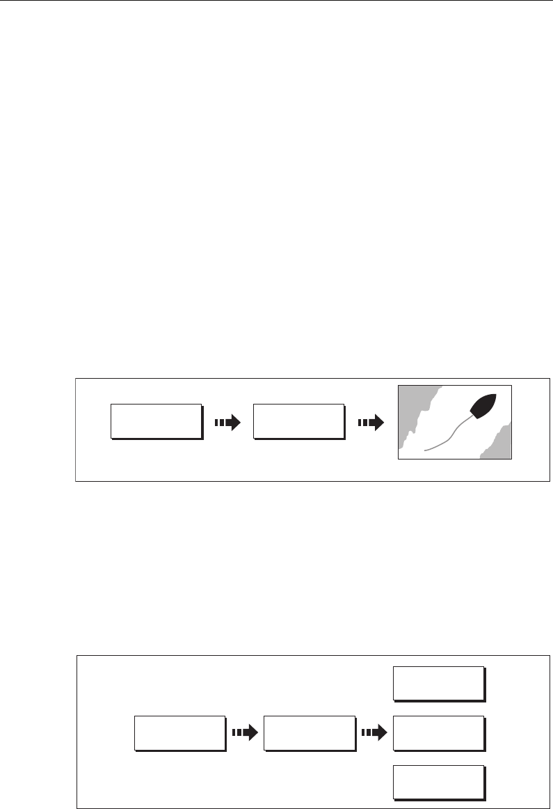
Chapter 4: Using the Chart 79
How can I use tracks?
Tracks can be used to:
• Review where you have been.
• Retrace your original journey by converting the track to a route and automatically
reversing it.
If required, a track can be personalized and the track options customized to your own
particular needs. You can:
• Rename a track.
• Change the color of a track.
• Specify the time period between track point creation (see
page 90
).
• Specify the distance between each track point (see
page 90
).
Creating a track
To start a track...
[
If the power fails whilst a track is being recorded or the position fix is lost, a break will
occur in the track. Only the last segment of a track can be converted into a route.
If the maximum number of tracking points is reached, you will be warned. The track
will continue to be recorded with the earlier tracking points being overwritten.
To stop the track...
Stop the tracking process:
D6500-2
TRACKS… START TRACK
Track laid from your boat
D6501-3
TRACKS… STOP TRACK DISCARD TRACK
SAVE TRACK
CANCEL STOP
COMMAND
Or:
Or:
81221_4.book Page 79 Tuesday, February 28, 2006 5:24 PM
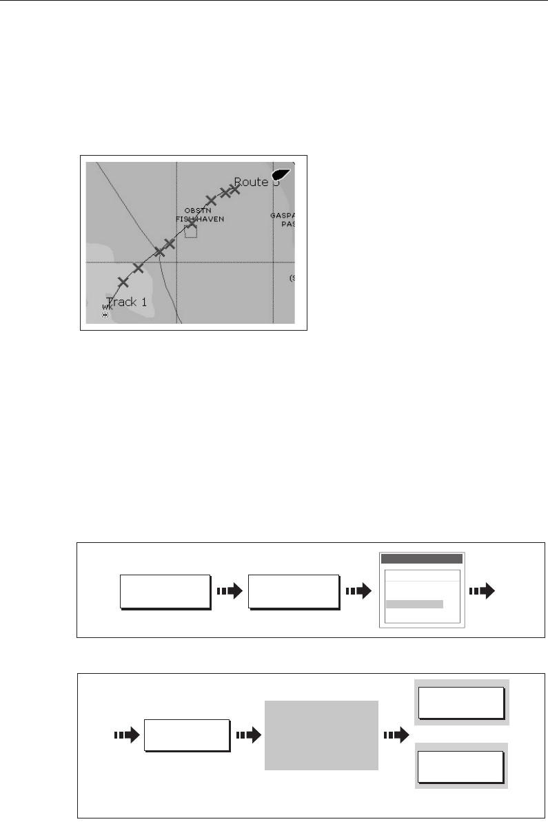
80 C-Series Display Reference Manual
Creating a route from a track
Creating a route from a track enables you to retrace the course of that track.
When a track is converted the system creates the closest route through the recorded
track, using the minimum number of waypoints. Each waypoint created will be saved
with the depth and temperature data (if applicable) for that position.
On completion, the maximum deviation of
the route from the recorded track is
displayed and the new route is added to
the route list. It can now be displayed,
edited and erased etc. in the same way as
other routes in the system.
Note:
If a track break occurs, only the last
segment is converted to a route.
CAUTION:
Before following the route, ensure that it is safe for navigation, noting that it
may deviate from your actual path travelled.
... from the current track
You can create a route from the track that you are currently laying. This method will
take a ‘snapshot’ of the track to date, convert it to a route and then continue laying the
track:
1. Select the track list:
2. Create a route from current track:
Note:
Alternatively you can also select the current track with the cursor and convert it
to a route.
D8366-1
D6505_3
CREATE ROUTE
FROM TRACK…
TRACKS…
Track List
Color Name
---- Track 1
---- Track 2
---- Track 3
---- Track 4
D8367_1
CREATE ROUTE
FROM TRACK…
YES
NO
Route generation completed.
Maximum deviation from
oritinal track equals 0,001nm.
Please check route before
navigating. Do you want to name
the route?
Route generated and
dialog box displayed
To accept default
(numbered)
Or
81221_4.book Page 80 Tuesday, February 28, 2006 5:24 PM
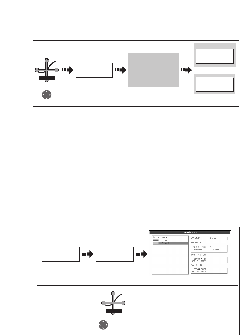
Chapter 4: Using the Chart 81
...from a saved track
You can create a route from a track that you have already saved:
Note:
Alternately you can select the track via the track list - see page 80.
4.16 Editing tracks
Once you have created a track, it can be edited in a variety of ways. You can:
• Change the name of a track (see
page 82
).
• Change the color of a track (see
page 82
).
• Erase a track (see
page 82
).
Selecting a track for editing
For a track to be edited it must first be selected either via the track list or by selecting
the appropriate track on-screen.
D8368_1
CREATE ROUTE
FROM TRACK…
YES
NO
Route generation completed.
Maximum deviation from
oritinal track equals 0,001nm.
Please check route before
navigating. Do you want to name
the route?
Route generated and
dialog box displayed
To name the route
To accept default
(numbered)
Track 2
Or:
TRACK
Position cursor
over track
TRACKS ... REVIEW AND
EDIT TRACKS ...
Highlight required track
D8674_1
Track 2
TRACK
Position cursor
over track
... via the track list
... via the cursor
81221_4.book Page 81 Tuesday, February 28, 2006 5:24 PM
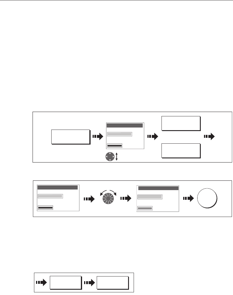
82 C-Series Display Reference Manual
Editing the selected track
Once you have selected the appropriate track (see previous section) you can proceed
to edit it.
Changing the name or color of a track
You can change the name of a track from the default to a more meaningful one and/or
change the color if required. This will make them easier to distinguish from one
another, particularly if you have numerous tracks in your system.
1. Select the appropriate track for editing (see
page 81
).
2. Select the Edit Name or Edit Color option:
3. Edit and save:
Erasing a track
You can delete any track in your system:
1. Select the appropriate track for editing (see
page 81
).
2. Erase the track:
You can also erase all or selected tracks, using the ARCHIVE & TRANSFER function as
described on
page 21
.
EDIT NAME AND
COLOR...
D8739_1
Select name
or color
Edit Track
Name
Tk1
Color
T
r
a
c
k
1
EDIT NAME
EDIT COLOR
Or
D8377_1
Edit Route
Name
Color
Da
rtm
ou
t
h
Edit color/name Save
OK
Edit Route
Name
Rt1
Color
R
ou
t
e
1
D8741-1
ERASE TRACK YES
81221_4.book Page 82 Tuesday, February 28, 2006 5:24 PM

Chapter 4: Using the Chart 83
4.17 Defining how the chart windows are presented
Each chart window can be tailored to meet your particular needs. You can:
• Set the chart view for individual windows or system wide (see below).
• Change how the chart is orientated (see
page 84
).
• Change the way your chart is drawn in relation to your boat movement (see
page 85
).
Working with multiple chart views
If you have more than one chart window, you can either share the presentation or
present each window independently. The option you have chosen is indicated on the
chart status bar as LOCAL or SYSTEM.
System chart view
When a chart application is started it defaults to system view. Any windows set to
system view will have the same presentation as other system windows for:
• Chart mode and orientation.
• Chart layers - radar and AIS.
• Radar/chart synchronization.
• Show/hide waypoints, routes and tracks.
• Declutter.
•Vectors.
If you change any of these options in one window, ALL system windows will update.
Local chart view
When local chart view is selected the presentation for each window is set
independently.
Defining chart window presentation
To define how the chart windows are presented:
Note:
The motion mode will be set but not synchronized across windows when the
chart view is set to system.
PRESENTATION CHART VIEW
LOCAL SYSTEM
D6586_3
81221_4.book Page 83 Tuesday, February 28, 2006 5:24 PM

84 C-Series Display Reference Manual
Setting the orientation of the chart
The orientation of a chart refers to the relationship between the chart and the direction
that you are travelling in. It is used in conjunction with motion mode (see
page 85
) to
control how your boat and chart relate to one another and how they are displayed on
screen. The mode that you choose is restored at power up. Any changes that you make
to a chart window that is set to system view will be reflected in all other system view
chart windows. The following options are available:
North Up (N-up)
In North Up mode, the chart orientation is fixed with true north upwards. As your
heading changes the boat symbol moves accordingly. This is the default mode for the
chart application.
Head Up (H-up)
Head Up mode displays the chart with your boat’s current heading upwards. As the
heading changes the boat symbol remains fixed and the chart picture rotates accord-
ingly.
Notes: (1)
To prevent continuous backwards and forwards rotations as the boat
yaws from side-to-side, the chart will not update unless the heading
changes by at least 10 degrees from the last displayed orientation.
(2)
It is not possible to select Head Up when the motion mode is set to True.
Course Up (C-UP)
In Course Up mode, the chart picture is stabilized and shown with your current course
upwards. As your boat’s heading changes, the ship symbol moves accordingly. If you
select a new course, the picture will reset to display the new course upwards.
The reference used for Course-Up depends upon the information available at a given
time. The system always prioritizes this information in the following order.:
1. Bearing from origin to destination, i.e. intended course.
2. Locked heading from an Autopilot.
3. Bearing to waypoint.
4. Instantaneous heading.
If heading data becomes unavailable whilst in this mode, a warning message will be
shown and the chart uses 0° heading in relative motion.
To set the orientation of the chart:
D6511_2
CHART MODE AND
ORIENTATION…
PRESENTATION… ORIENTATION
H-UP N-UP C-UP
81221_4.book Page 84 Tuesday, February 28, 2006 5:24 PM
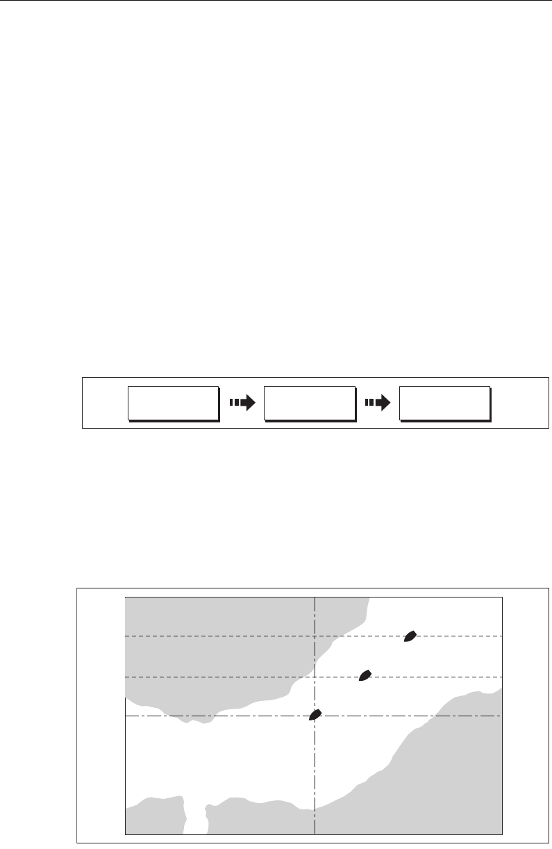
Chapter 4: Using the Chart 85
Setting the motion mode
The motion mode controls the relationship between the chart and your boat. Whilst
motion mode is active, as your boat moves, the chart is redrawn to keep the boat on-
screen. The three motion modes are:
•Relative motion.
• True motion.
•Autorange.
When you pan the chart or toggle FIND SHIP/CURSOR to CURSOR, the motion mode is
suspended. This is indicated in the status bar by ‘( )’ around the motion mode and
enables you to view another area of the chart whilst navigating. To reset the motion
mode and return your boat to the screen, press FIND SHIP. Manually changing the
range in autorange also suspends motion mode.
The default setting is relative motion with zero offset. The mode that you select is
restored at power up. When a chart window is set to SYSTEM view the motion mode
will be set but not synchronized across other system view windows.
Relative motion (RM) with optional vessel offset
When the motion mode is set to Relative, the position of your boat is fixed on the
screen and the chart picture moves relative to your boat.
You can specify using the VESSEL OFFSET soft key, whether the boat is fixed in the
centre of the window (0 offset) or offset by 1/3 or 2/3. If you change the offset to 1/3 or
2/3, the view ahead of your boat will be increased.
D6512-2
CHART MODE AND
ORIENTATION…
PRESENTATION… MOTION MODE
TM RM AR
D6839_3
0 Vessel offset
1/3 Vessel offset
0 Vessel offset
81221_4.book Page 85 Tuesday, February 28, 2006 5:24 PM
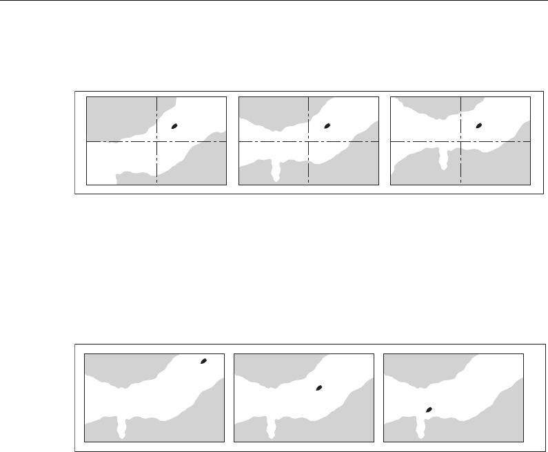
86 C-Series Display Reference Manual
In the following example the motion mode has been set to Relative with a vessel offset
of 1/3. The boat is fixed in the offset position and the chart moves accordingly:
True motion (TM)
When the motion mode is set to True, the chart is fixed and the boat moves in true
perspective to fixed landmasses on the screen. As the boat’s position approaches the
edge of the screen, the chart picture is automatically reset to reveal the area ahead of
the boat.
Note:
It is not possible to select True Motion when the orientation is set to Head Up.
Autorange
Autorange selects and maintains the largest possible scale of chart that will display
both the boat and the target waypoint. Autorange is not available if radar-chart
synchronization is on.
4.18 Altering the level of chart detail displayed
The chart features that you need to see will vary according to your particular needs and
circumstances. You can adjust this level of detail by showing/ hiding the following
features:
•Waypoints.
• Waypoint index of a route.
• Individual routes and tracks.
• Cartographic features.
• Chart vectors for COG, heading, tide and wind (see
page 74
)
Note:
You can also specify the level of detail on the chart display (simple, detailed or
extra detailed). For more details, see page 93.
D6840_2
D6841-2
81221_4.book Page 86 Tuesday, February 28, 2006 5:24 PM
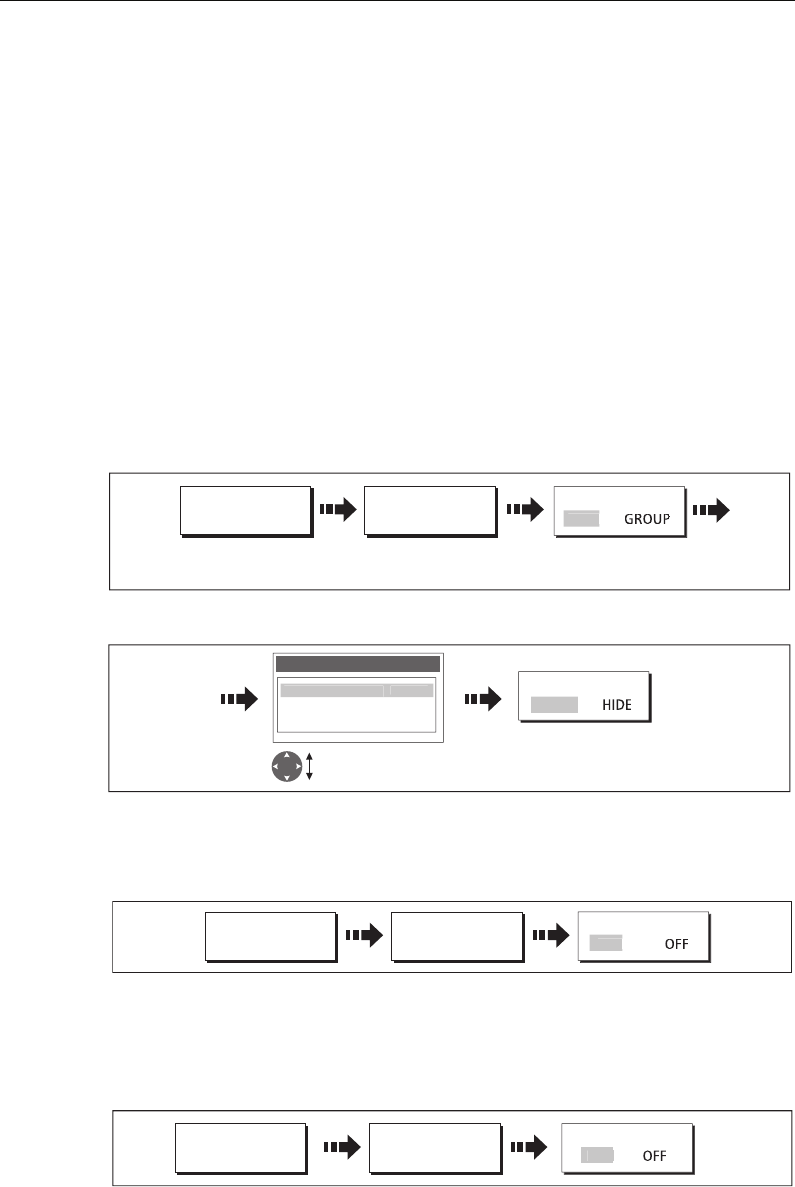
Chapter 4: Using the Chart 87
Showing or hiding waypoints/waypoint information
The system has various options to control the display of waypoints and waypoint
information. You can show or hide all your waypoints and their names or show or hide
waypoints by group or by symbol.
These options are particularly useful when you have placed a large number of
waypoints in a small area and rendered your chart difficult to interpret.
Note:
The show/hide status of a waypoint is a local setting and will therefore only af-
fect the individual display on which you are working.
Show/hide by group/symbol
You can show or hide waypoints with a particular symbol or belonging to a specified
group:
1. Select to show/hide by waypoint group or symbol:
2. Change status to show or hide as required.
Show/hide waypoint name
You can show or hide the waypoint names from the screen:
Show/hide waypoint index
The order of waypoints within a route is indicated by the waypoint index. To show/hide
this index:
SHOW/HIDE
WAYPOINTS...
SHOW BY
PRESENTATION...
D6879_2
Toggle to symbol or
group
S
YM
ON CHART
D8383_1
Select relevant group
Toggle to required
status
SHOW BY GROUP
Fishing SHOW
Diving HIDE
M
y
Wa
yp
oints SH
O
W
S
HOW
D6881_2
SHOW/HIDE
WAYPOINTS ...
WAYPOINT NAME
PRESENTATION…
O
N
WAYPOINT INDEX
D6595-2
SHOW/HIDE
ROUTES…
ROUTES…
O
N
81221_4.book Page 87 Tuesday, February 28, 2006 5:24 PM
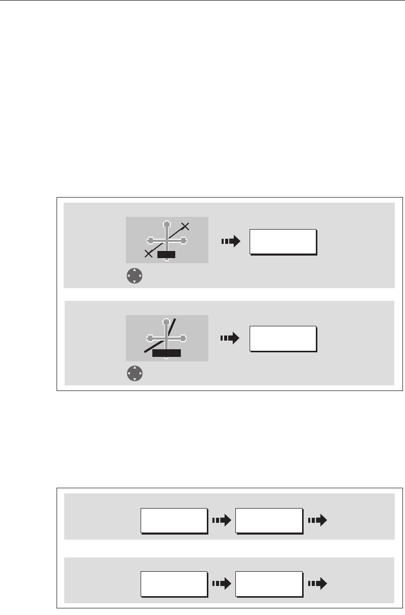
88 C-Series Display Reference Manual
Showing or hiding a route or a track
You can define which routes or tracks are shown or hidden from the screen. When a
route is set to HIDE, the route line is not displayed. The display of waypoints within a
hidden route depends however on the show/hide waypoint setting (see
page 87
). The
active route is always displayed irrespective of the display status.
Note:
The show/hide status of a route or track applied to a chart window that is set to
system view, will be displayed in all other system view chart windows.
... using the cursor
You can use the cursor method to hide a route or track.
Note:
Use the route/track list to return the display status to SHOW.
... via the route/track list
You can show or hide a route /track via the appropriate list:
1. Select the Show/Hide Route or Show/Hide Track option:
2. Select required route or track:
D8390_1
HIDE ROUTE
HIDE TRACK
Move cursor over
appropriate route
Move cursor over
appropriate track
Routes
Tracks
Or
TRACK
RTE
D8388-1
SHOW/HIDE
ROUTES…
ROUTES…
Routes
Tracks
SHOW/HIDE
TRACKS…
TRACKS…
Or:
81221_4.book Page 88 Tuesday, February 28, 2006 5:24 PM
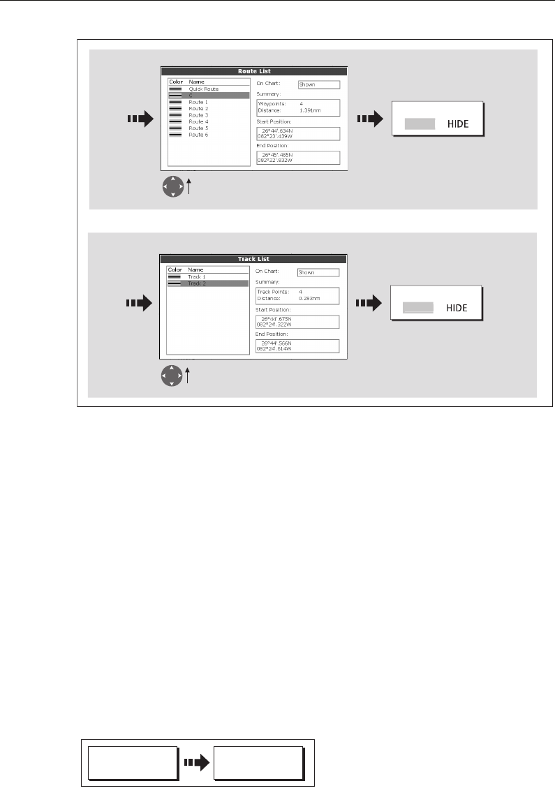
Chapter 4: Using the Chart 89
Showing or hiding cartographic features
If there are a large number of cartographic objects in a particular area, you can reduce
the amount of detail by de-cluttering the chart display. Turning declutter on hides the
following cartographic objects:
•Text.
• Chart boundaries.
• Spot soundings.
• Depth contours.
•Light sectors.
• Caution & routing data.
• Land and marine features.
• Business services (if available on your cartography)
To declutter your chart:
If the declutter option is applied to a chart window that is set to SYSTEM view, the
declutter will be applied to all other system view chart windows. If decluttering does
not hide/show the particular features of your choice, they can be turned on/off
individually via the Cartography Setup menu (see
page 93
).
D8389-1
ROUTE ON CHART
S
H
O
W
Highlight required route
Routes
Tracks
Highlight required track
Set to SHOW or HIDE
as required
Set to SHOW or HIDE
as required
TRACK ON CHART
S
H
O
W
Or
PRESENTATION
D6492-2
DECLUTTER
ON OFF
81221_4.book Page 89 Tuesday, February 28, 2006 5:24 PM
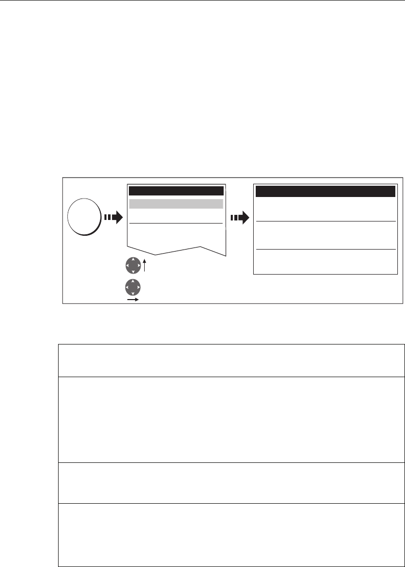
90 C-Series Display Reference Manual
4.19 Setting up your chart and its cartography
The set up for your chart and its cartography can be changed from the standard
configuration to suit your particular needs. Although you will probably only do this
when you first use the chart, you may decide to make subsequent adjustments once
you become more familiar with the system. Any settings that you change are retained
even when you power off.
Chart Setup
To select the Chart Setup Menu:
The following table details the functions and options within the Chart Setup menu:
FUNCTION
Description
OPTIONS
(Default in bold)
Object Information
OFF - No info pop-up is displayed but detailed data can still be dis-
played by pressing OK.
ALL ON - the info pop-up for all cartographic areas (including
objects) is displayed.
Points ON - the info pop-up only displayed for objects selected with
the cursor.
OFF
All ON
Points ON
Vector Length
The time period specified for drawing COG and Heading vectors.
3 Mins
6 Mins
Infinite
Record Vessel Track By
AUTO - system automatically creates track points.
TIME - for track point creation by time.
DISTANCE - for track point creation by distance.
Auto
Time
Distance
D8391_1
MENU
Chart Setup Menu
Object Information Points ON
Vector Length Infinite
Record Vessel Track By Time
Track Interval 1 secs
Datum WGS 1984
Chart Offset...
Setup
Cartography Setup
GPS Status...
Compass Setup...
C
hart Setup..
.
Highlight Chart Setup menu
Enter Chart Setup menu
81221_4.book Page 90 Tuesday, February 28, 2006 5:24 PM

Chapter 4: Using the Chart 91
Datum
For your GPS and chart to correlate accurately with your paper charts, they will need to
be using the same datum. The default datum for your display is WGS1984. If this is not
suitable, you can change the setting. When you adjust the datum of the C-Series
Display, a Raymarine GPS will automatically correlate. If you have a third party GPS,
you will need to correlate this separately.
CAUTION:* Changing the chart datum does
not
cause any waypoint or routes
stored in the chartplotter to move on the display, although their latitude and
longitude changes to reflect the new datum.
When adding waypoints numerically to the waypoint list, or via SeaTalk or
NMEA, it is important that they are referenced to the same datum to which
the display is currently set.
Chart Offset
This feature allows you to move the position of the chart in order to correct for position
errors in the cartography. This adjustment is indicated as a distance north/west (+ve)
or south/east (-ve) from your vessel position to a maximum of 1000m. To view the
effects of an offset you can turn the feature on/off. Once calculated, the offset is
applied to all charts.
Track Interval
Options available depend on setting in Record Vessel Track By
function:
TIME - specify time period between track points creation.
DISTANCE - specify distance between track points creation.
AUTO - no options available
TIME selected:
1 sec
5 secs
10 secs
30 secs
1 min
3 min
5 min
10 min
30 min
DISTANCE selected:
0.1 nm
0.5 nm
1.0 nm
Datum
Grid moves according to datum selected and the lat/lon of carto-
graphic features change. System attempts to set up any GPS to the
new mode and indicates whether successful or not. See additional
information below.
WGS 84
List of datum provided
Chart Offset
Moves the position of the chart in order to correct for position
errors in the cartography. See below for further information.
ON
OFF
FUNCTION
Description
OPTIONS
(Default in bold)
81221_4.book Page 91 Tuesday, February 28, 2006 5:24 PM
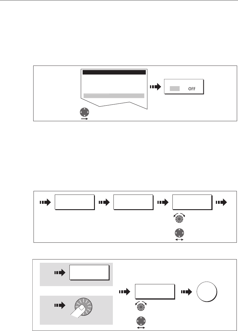
92 C-Series Display Reference Manual
Important: Any offset entered will be applied to all charts on the chart card. You
should therefore ensure that this feature is switched off once you have transitioned off
of the errant chart. Any charting errors that you discover should be reported to
Navionics (see
page 201
).
To switch on chart offset:
Note:
If your vessel position is not available, the current chart centre is used as the ref-
erence point.
Changing the offset value
To change the offset value:
1. Select the Chart Offset function (see previous section)
2. Set the north/south offset value:
3. Set the east/west offset value:
Resetting the offset value
To reset the chart offset to zero:
1. Select the Chart Offset function (see previous section).
2. Reset to zero:
D7187-3
Alarm Setup Menu
Object Information Points ON
Vector Length Infinite
Datum WGS 1984
C
hart Offset..
.
Select Chart Offset
Toggle to ON
OFFSET
O
N
D7188_3
SET OFFSET... ADJUST N-S
0ft
ADJUST N-S
-80ft
Adjust North/
South level as
required.
or:
D8384_1
ADJUST E-W
0ft
ADJUST E-W
121ft
Adjust East/ West
level as required.
OK
Press
Or
or:
81221_4.book Page 92 Tuesday, February 28, 2006 5:24 PM
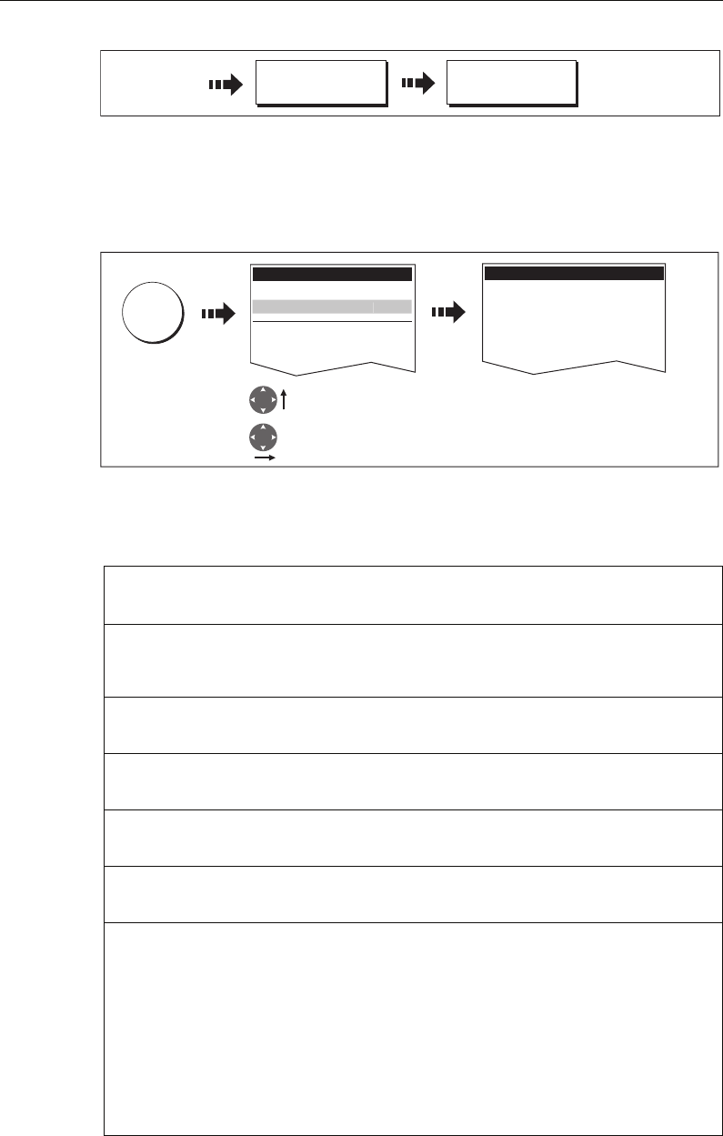
Chapter 4: Using the Chart 93
Cartography Setup
The Cartographic Setup Menu allows you to configure what is displayed on your chart:
To select the Cartography Setup Menu:
The following table details the functions and options within the Cartography Setup
menu:
FUNCTION
Description
OPTIONS
(Default in bold)
Chart Display
The level of detail shown on the chart.
Simple
Detailed
Extra detailed
Chart Grid
Grid lines of latitude and longitude.
ON
OFF
Chart Text
Text appearing on the chart e.g. place names etc.
ON
OFF
Chart Boundaries
The line indicating the boundary of the chart.
ON
OFF
Spot Soundings
Number on the chart indicating depth.
ON
OFF
Safety Contour
Areas with depths shallower that the specified value, are shaded in
a darker blue than those areas with depths greater than the speci-
fied value.
OFF
6ft
9ft
16ft
19ft
32ft
65ft
(Contour always drawn at or
deeper than the selected
depth).
D8393_1
SET OFFSET... CLEAR OFFSET
D8392_1
MENU
Setup
Chart Setup...
GPS Status...
Compass Setup...
Highlight Cartography
Setup menu
Enter Cartography
Setup menu
Cartography Setup Menu
Chart Display Detailed
Chart Grid On
Chart Text On
Chart Boundaries ON
Spot Soundings ON
Carto
g
rap
h
y Setup..
.
81221_4.book Page 93 Tuesday, February 28, 2006 5:24 PM

94 C-Series Display Reference Manual
Depth Contour
A line indicating the depth at a particular position.
ALL
16ft
19ft
32ft
65ft
OFF
Nav. Marks ON
OFF
Nav. Marks Symbols
The set of symbology used for navigation marks.
Corresponds to paper charts.
International
US
Light Sectors
The sector of light cast by a fixed beacon.
ON
OFF
Caution & Routing Data ON
OFF
Marine Features
The following cartographic features displayed on the water -
cables, nature of seabed points, tide station, current stations and
port information.
ON
OFF
Land Features
The cartographic features that are displayed on the land.
ON
OFF
Colored Seabed Areas
In available areas (e.g. Portugal) this gives greater definition of
seabed.
ON
OFF
Background Color
The color of background water when there is no Navionics cartog-
raphy.
White
Blue
Business Services
The symbols indicating the location of a business
ON
OFF
Roads
Major coastal roads
ON
OFF
Additional Wrecks
Extended wrecks data for new wrecks
ON
OFF
FUNCTION
Description
OPTIONS
(Default in bold)
81221_4.book Page 94 Tuesday, February 28, 2006 5:24 PM

Chapter 5: Using the Fishfinder 95
Chapter 5: Using the Fishfinder
5.1 Introduction
This chapter describes how the Fishfinder uses sonar to see fish, bottom structure and
texture, and underwater obstructions such as wrecks.
The standard fishfinder image is a historical, scrolling bottom graph at an
automatically selected range and frequency. Various functions are provided to
improve the underwater view, select what is displayed and sound an alarm including:
• Changing the view displayed (Zoom, A-Scope or Bottom Lock).
• Adjusting the range and zoom.
•Shifting the image.
• Simplifying the bottom image and isolating bottom fish.
• Pausing the scrolling image.
• Switching the depth digit on/off.
• Using waypoints to mark a position.
• Determining depths and distances of targets.
• Fishfinder alarms (fish, depth or water temperature).
• Setting up the fishfinder application including manually adjusting the frequency
and adjusting the gain values.
Note:
Please refer to the Installation Guide for fishfinder calibration information.
5.2 How does the Fishfinder work?
The fishfinder application uses a Digital Sounder Module (DSM) to process sonar
signals from a suitable transducer and provide a detailed underwater view.
The transducer located on the bottom of the boat sends pulses of sound waves into the
water and measures the time it takes for the sound wave to travel to the bottom and
back. The returning sound echoes are affected by bottom structure and by any other
objects in their path, e.g. fish, wrecks, reefs.
The Digital Sounder Module (DSM) processes these echoes and sends data to the
fishfinder which displays a visual interpretation of the underwater view. The strength
of echoes is indicated on the display by different colors. You can use this information to
determine the bottom structure, the size of fish and other objects in the water e.g.
debris, air bubbles.
Notes: (1)
The DSM will operate at a frequency of 50 kHz or 200 kHz.
(2)
Some transducers will also enable the fishfinder to display water
temperature and/or speed.
81221_4.book Page 95 Tuesday, February 28, 2006 5:24 PM
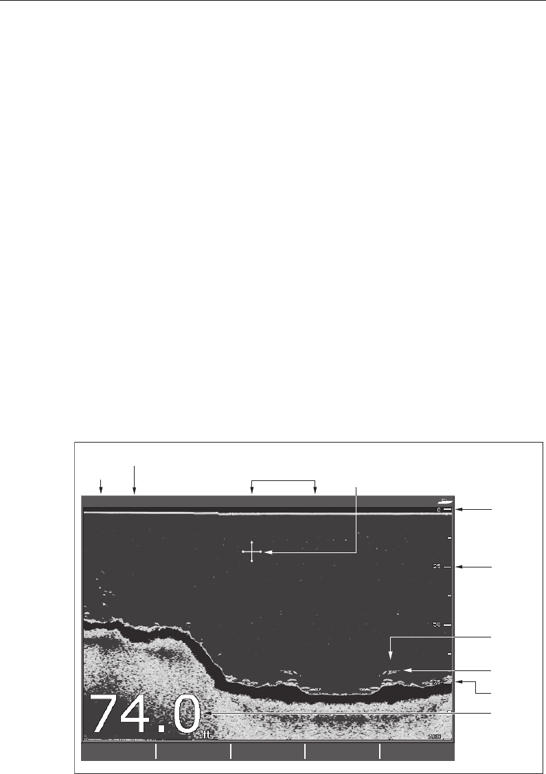
96 C-Series Display Reference Manual
5.3 What can the fishfinder show me?
When you first view the fishfinder application, an image representing the echoes seen
by the DSM is displayed. As time passes this image scrolls from right to left and
becomes a record of the echoes seen. The images at the right hand side of the display
are therefore the most recent.
The fishfinder window will display:
• The bottom together with any bottom structure such as reefs and shipwrecks etc.
• Target images indicating fish.
• A status bar noting the frequency and gain settings.
• The bottom depth.
You can customize the fishfinder to:
• Hide the depth of the targets - see
page 106
.
• Show the depth lines - see
page 113
.
• Change the color palette and the depth displayed - see
page 113
.
• Pause or change the scroll speed - see
page 105
.
• Enable a fish, shallow or deep water alarm - see
page 110
and
page 188
• Adjust the DSM and Transducer to suit local conditions - see
page 110
.
6869
50
FISHFINDER
SETTINGS... ZOOM... BOTTOM
LOCK... A-SCOPE... PRESENTATION...
200 kHz: Auto Gain: Auto High
Cursor -
controlled
by trackpad
D6669-4
Depth
markers
Target
Bottom
Bottom of
transducer
Frequency Gain mode
Frequency mode
Target
depth
Bottom
depth
81221_4.book Page 96 Tuesday, February 28, 2006 5:24 PM
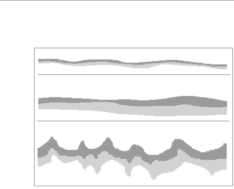
Chapter 5: Using the Fishfinder 97
Interpreting the bottom structure
The bottom usually produces a strong echo. These images indicate the bottom
conditions as follows:.
The dark layers indicate a good echo; the lighter areas weaker echoes. This could mean
that the upper layer is soft and therefore allowing sound waves to pass to the more
solid layer below.
It is also possible that the sound waves are making two complete trips – hitting the
bottom, bouncing off the boat, then reflecting off the bottom again. This can happen if
the water is shallow, the bottom is hard, or gain is set high.
The Fishfinder provides various features to help you interpret the fishfinder picture.
Factors influencing target display
The shape and size of this mark is influenced by a combination of factors:
Boat speed
The shape of the target changes along with your speed. Slower speeds return flatter,
more horizontal marks. As your boat’s speed increases, the target will tend to thicken
and arch slightly; until at fast speeds the mark resembles a double vertical line.
The depth of the target
The closer the target to the surface the larger the mark on screen.
D6855-2
A hard bottom (sand) produces a thin line
A soft bottom (mud or seaweed cover) produces a wide line.
The dark layer indicates a strong signal.
A rocky or uneven bottom or a wreck produces an irregular
image with peaks and troughs
81221_4.book Page 97 Tuesday, February 28, 2006 5:24 PM
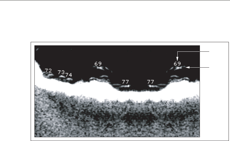
98 C-Series Display Reference Manual
Note:
The depth of individual targets can be displayed by switching on the Target
Depth ID in the Fishfinder Setup Menu. The number of target depths displayed is influ-
enced by the fish alarm sensitivity level (see page 188).
The size of the target
The larger the target, the larger the return on the fishfinder display. The size of a fish
target is however dependent upon the size of the fish’s swim bladder rather than its
overall size. This swim bladder will vary in size between different breeds of fish.
The frequency of the transducer
The same target will appear differently when the transducer frequency is changed. The
lower the frequency the broader the mark.
Factors impairing a fishfinder picture
Although weaker than the fish or bottom echoes, your fishfinder picture may be
impaired by echoes received from floating or submerged debris, air bubbles or from
your boat’s movements. This is known as background noise or clutter and is controlled
by the gain modes (gain, color gain and TVG). Raymarine recommends that you allow
your system to automatically control the ideal sensitivity level based on depth and
water conditions. You can however adjust these settings manually if you prefer. For
more details, please refer to
page 116
.
Seeing a live image
The standard fishfinder display shows a historical record of fishfinder echoes. If
required, you can display a live image of the bottom structure and the fish directly
below the transducer by using the A-Scope feature. The width of the bottom covered
by the A-Scope is indicated at the bottom of the window. A-Scope provides a more
precise and easier to interpret indication of the target strength.
Target
Target
depth
D6890-2
81221_4.book Page 98 Tuesday, February 28, 2006 5:24 PM
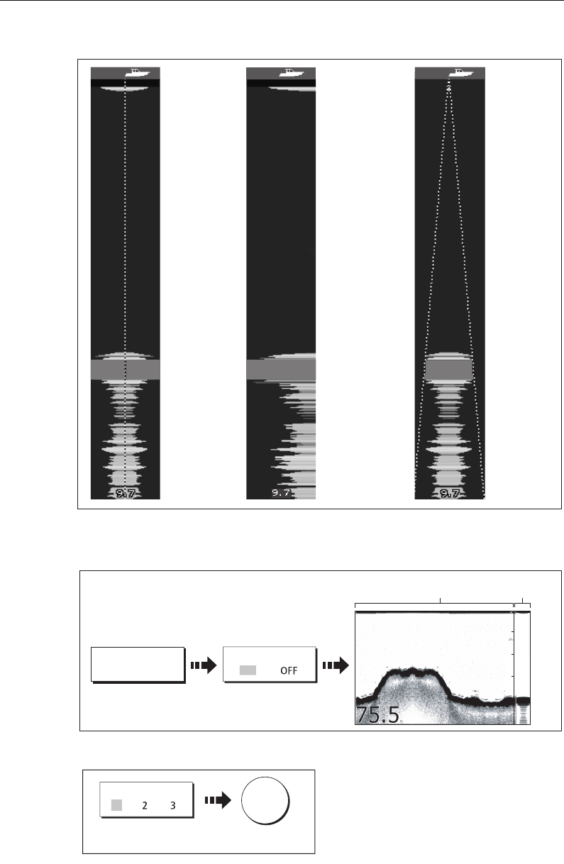
Chapter 5: Using the Fishfinder 99
There are three A-Scope modes which are selected for individual fishfinder windows:
I
To display the A-Scope image:
1. Select the A-Scope option:
2. Select the required A-Scope mode:
Note:
Selecting A-Scope automatically switches OFF Bottom Lock and Zoom.
D6674-3
MODE 1
The A-scope
image is centred
in the window.
MODE 2
The left-hand side
of the Mode 1
image is expanded
to give a more
detailed view.
MODE 3
The A-scope
image angles
outward as
signal width
increases with
depth.
D6675-2
A-SCOPE... A-SCOPE
O
N
Toggle to ON
0
20
30
40
50
Standard fishfinder image
A-scope
image
OK
A-SCOPE MODE
D8439_1
1
Toggle to required
mode
81221_4.book Page 99 Tuesday, February 28, 2006 5:24 PM
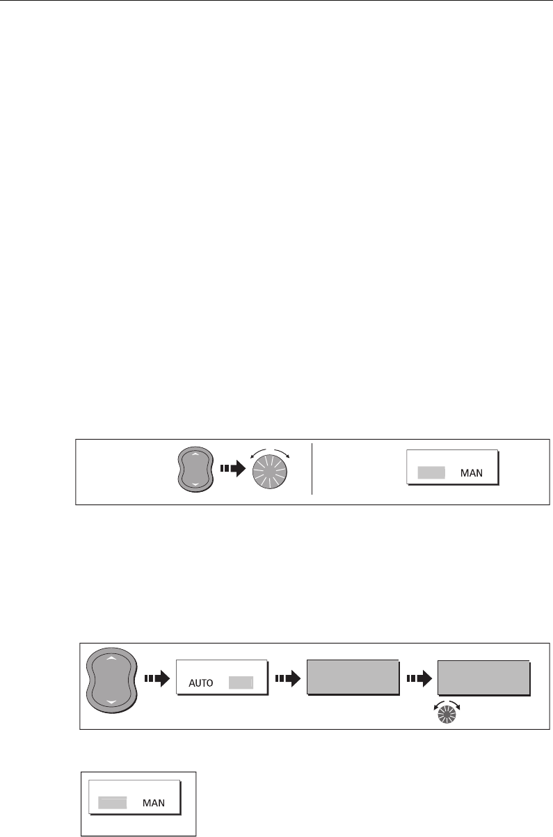
100 C-Series Display Reference Manual
5.4 Enhancing what you see
You can enhance the image by applying the following options:
• Change the range (Range).
• Shift the selected viewing range (Range Shift).
• View a zoomed area (Zoom).
• Flatten the bottom image to help separate fish from the bottom (Bottom Lock)
• Isolate bottom fish (White Line/Bottom Fill)
• Pause the scrolling image or adjust the rate at which the image scrolls (Scroll Pause/
Scroll Speed)
• Change the size of or remove the depth digit.
Changing the range
The DSM automatically adjusts the display to show the shallowest required range.
Alternatively, you can select to range in/out on the image (up to the maximum depth
displayed on the scrolling bottom and A-Scope images). Changes to the range are
reflected in all Fishfinder windows.
To select manual/auto range mode:
Shifting the image
The DSM automatically adjusts the display to keep the bottom in the lower half of the
display window. Alternatively, you can shift the image within the current range.
Changes to the range shift are reflected in all Fishfinder windows.
To shift the image:
To return to the standard fishfinder image:
D6585-1
RANGE
IN
OUT
D8440_1
To select and
adjust manual
range mode:
To return to
autorange:
RANGE
AUTO
Toggle to AUTO
D8441_1
e.g.
RANGE
MA
N
RANGE SHIFT
0FT
Toggle to MAN Press to highlight Adjust shift value
as required.
D6585-1
RANGE
IN
OUT
RANGE SHIFT
5FT
D8442_1
RANGE
AUT
O
Toggle to AUTO
81221_4.book Page 100 Tuesday, February 28, 2006 5:24 PM
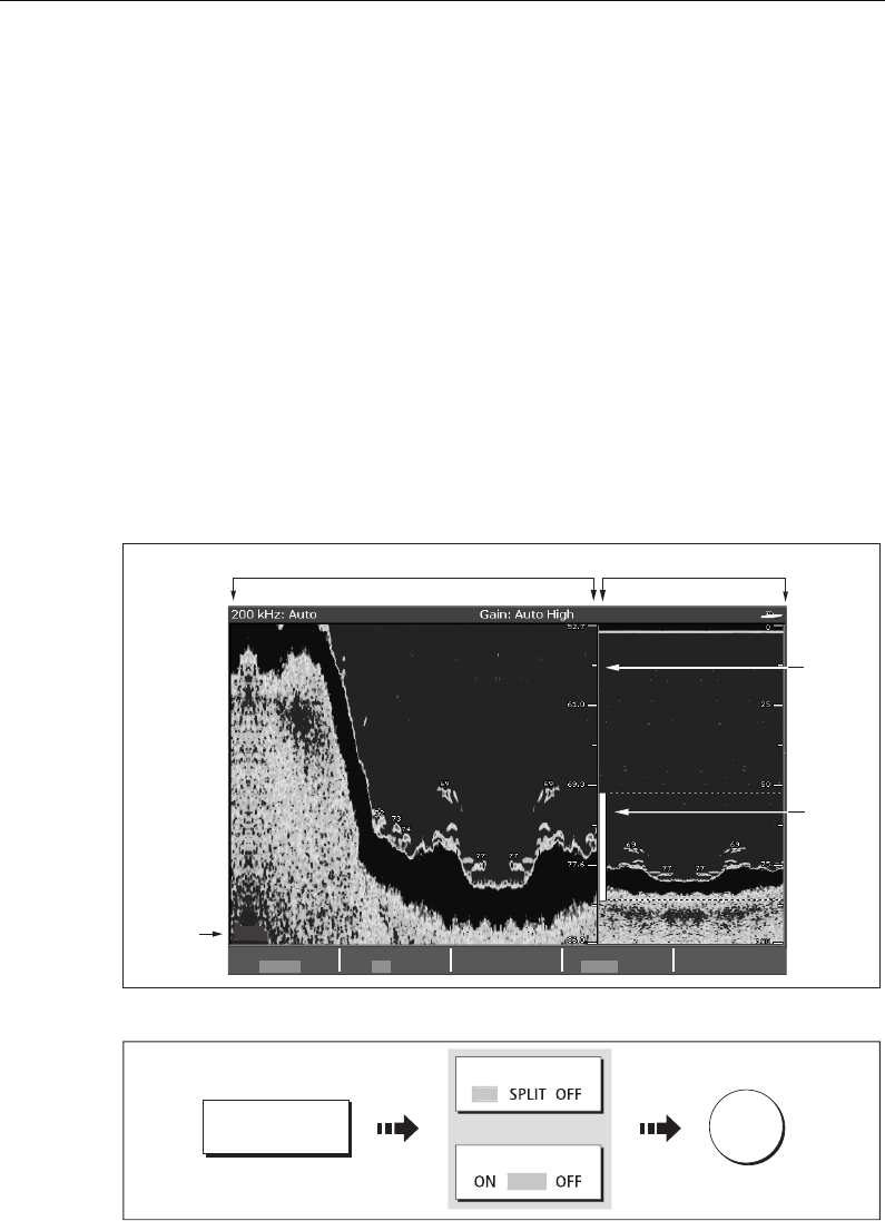
Chapter 5: Using the Fishfinder 101
Zooming in on the bottom
If necessary you can zoom in on the bottom to display more detail. This zoom option
enables you to:
• Replace the standard fishfinder image with the zoomed image or display the
zoomed image alongside the standard fishfinder image.
• Set to zoom level to one of the pre-defined zoom factor levels or adjusted manually.
• Reposition the portion of the image to be zoomed, if required.
Note:
When the range increases, the area shown in the zoom window also increases.
Selecting a split or full screen zoomed image
You can either replace the standard fishfinder image with the zoomed image (ZOOM
ON) or split the screen and display the zoomed image alongside the standard
fishfinder image (ZOOM SPLIT). The zoomed section is indicated on the standard
fishfinder screen by a zoom box (see illustration below).
To select a split or full screen:
ZxR
ZOOM START
52.7ft
ZOOM RANGE
4500ft
ZOOM FACTOR
x2 x3 x4 xR
ZOOM POSITION
AUTO MAN
ZOOM
ON SPLIT OFF
Zoom
box
Zoom
indicator
Standard fishfinder image
Zoom range box
D6676-3
Zoom
range
D8443_1
ZOOM...
ZOOM
ZOOM
O
N
SPLIT
Or
OK
81221_4.book Page 101 Tuesday, February 28, 2006 5:24 PM
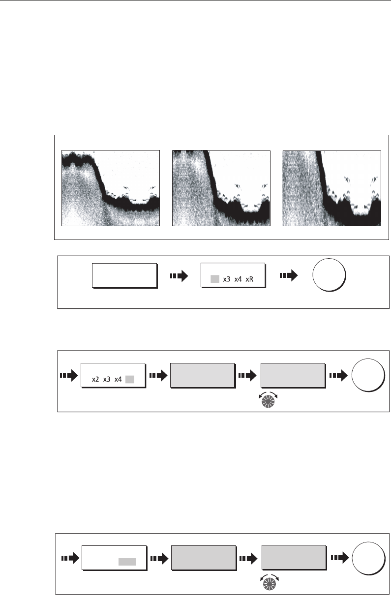
102 C-Series Display Reference Manual
Selecting the zoom factor
When the zoom function is active (ZOOM ON or ZOOM SPLIT), you can select either
a predefined zoom factor or you can adjust the zoom factor manually.
Pre-defined zoom factor
Select x2, x3 or x4 for a predefined zoom level. The greater the factor, the smaller
the area you are viewing and therefore the smaller the zoom box. These factors are
proportioned to the range e.g.
Manual zoom adjustment
To manually adjust the range shown in the zoom window:
Adjusting the position of the zoomed area
When the zoom function is selected, the system automatically selects the zoom
position so that the bottom details are always in the lower half of the display. If
required you can reposition the portion of the image to be zoomed so that an
alternative area is displayed.
With the zoom function set to ON or SPLIT:
Note:
Selecting Zoom automatically switches off Bottom Lock and A-Scope images.
D8835_1
x2
Zoom factor
x3 x4
ZOOM...
Toggle to x2, x3 or
x4 zoom factor
ZOOM FACTOR
x2
OK
D8836_1
Toggle to xR zoom
factor
ZOOM FACTOR ZOOM FACTOR
20ft
ZOOM FACTOR
10ft
x
R
OK
D8837_1
e.g. e.g.
Highlight soft key Adjust the zoom
factor as required
D8444_1
ZOOM START
29ft
Highlight soft key Reposition zoomed
image as required
OK
ZOOM START
31ft
ZOOM POSITION
AUTO MAN
e.g. e.g.
81221_4.book Page 102 Tuesday, February 28, 2006 5:24 PM
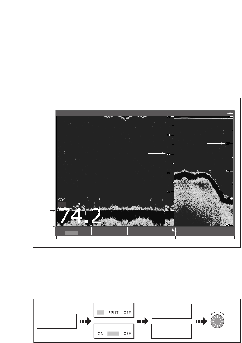
Chapter 5: Using the Fishfinder 103
Simplifying the bottom image
When you are looking for fish that feed close to the bottom, you can use the Bottom
Lock function to filter out and flatten the bottom structure and display the fish (or any
other objects directly above the bottom) more clearly.
Bottom Lock is selected for individual fishfinder windows and can either replace (ON)
or appear alongside (SPLIT) the standard fishfinder image.
Note:
If the A-Scope or Zoom image was displayed, selecting Bottom Lock automati-
cally switches OFF A-Scope and Zoom.
Adjusting bottom lock range/position
Adjusting the range of the bottom lock image allows you to view more bottom details.
You can also reposition the image on screen to anywhere between the bottom of the
window (0%) and the middle of the window (50%):
BL
B-LOCK RANGE
50ft
BOTTOM SHIFT
14%
BOTTOM LOCK
ON SPLIT OFF
200 kHz: Auto Gain: Auto High
Depth from the surface
D6672-3
Bottom lock range (distance from bottom)
Bottom
shift
Depth
reading
Bottom lock image Standard fishfinder image
D8445-1
BOTTOM LOCK...
BOTTOM LOCK
BOTTOM LOCK
O
N
SPLIT
SPLIT
B-LOCK RANGE
20ft
Adjust as
required
BOTTOM SHIFT
10%
81221_4.book Page 103 Tuesday, February 28, 2006 5:24 PM
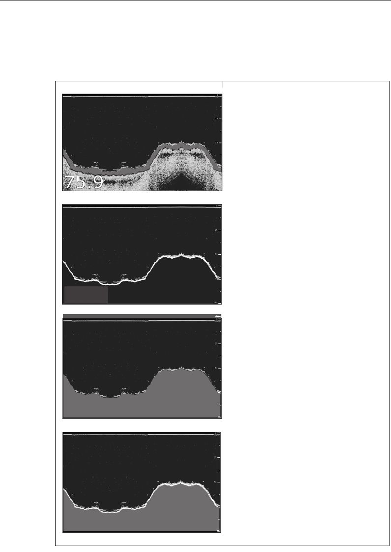
104 C-Series Display Reference Manual
Isolating bottom fish
You can separate the echoes from fish near the bottom and from the bottom itself by
using the White Line and/or the Bottom Fill features.
Note:
White Line and Bottom Fill are selected for individual fishfinder windows.
75.9
ft
100
75
200 kHz: Auto Gain: Auto High
75.9
ft
100
75
200 kHz: Auto Gain: Auto High
75.9
ft
200 kHz: Auto Gain: Auto High
75.9ft
75
200 kHz: Auto Gain: Auto High
D6833-3
Standard fishfinder image
The standard fishfinder image displays the
bottom as a combination of features (mud,
sand, fish targets etc) with various sonar
signal strengths.
White line
When this feature is applied, a white lIne
is drawn along the bottom (as defined by
the digital depth value) and the detail
below the bottom removed.
Fish near the bottom can now be seen
more easily.
Bottom fill
When this feature is applied, the detail
below the bottom is removed and
replaced by a single contrasting color.
The bottom is now clearly defined and the
fish near the bottom can be seen more
easily.
White line and bottom fill
When both White Line and Bottom Fill
are applied, the bottom is defined by a white
line and the detail below it replaced by a
single contrasting color.
Both the bottom and fish near the bottom
are now clearly defined.
81221_4.book Page 104 Tuesday, February 28, 2006 5:24 PM
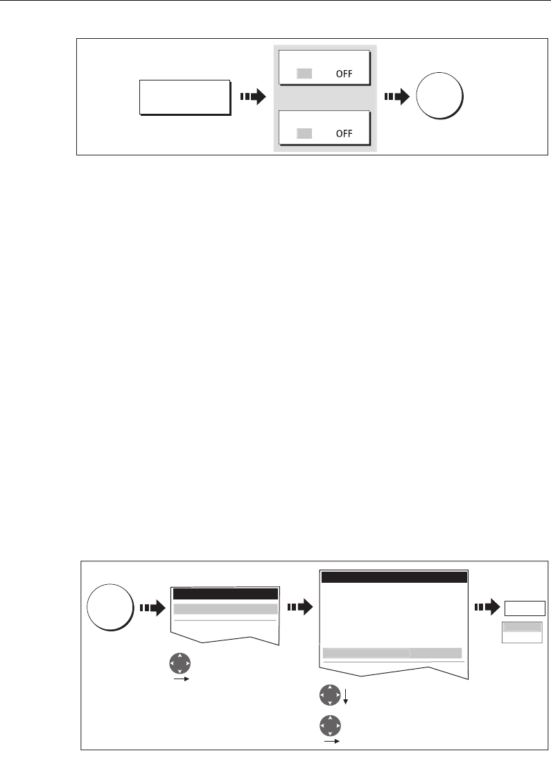
Chapter 5: Using the Fishfinder 105
Changing how the image scrolls
Adjusting the scroll mode and speed
You can adjust the speed at which the display scrolls, but the same section of the
bottom is displayed regardless of scrolling speed. A faster speed displays more detail.
This is useful when you are looking for fish. If you select a slower speed the information
remains on the display for longer.
The following options are available:
•Manual - This allows you to set the scroll speed as a percentage of the maximum
scroll rate for that depth. The lower the percentage, the slower the image will scroll.
The default is manual adjustment with a full speed scroll (100%).
•Automatic - The system automatically adjusts the scroll speed, based on boat
speed:
• Less than, or equal to 0.5 kts, scroll speed is constant at 10%.
• Between 0.5–15 kts, scroll speed varies linearly with boat speed.
• Greater than 15 kts, scroll speed is constant at 100%.
To select the scroll mode and speed:
Note:
If you have configured a transducer with no paddle wheel, selecting
AUTO
will
result in full speed scrolling (100%).
D6678-3
PRESENTATION...
WHITE LINE
BOTTOM FILL
and/or
O
N
ON
OK
D8448_1
MENU
Setup
GPS Setup...
Enter Fishfinder
Setup menu
Highlight scroll mode/manual
scroll speed as required
Fishfinder Setup Menu
Depth Digit Size LARGE
Depth Digit Position BOTTOM
Target Depth ID OFF
Depth Lines OFF
Color Palette Copper
Scroll MANUAL
F
ishfinder Setup..
.
Enter selection
100%
AUTO
M
ANUA
L
Manual Scroll S
p
eed
1
00
%
81221_4.book Page 105 Tuesday, February 28, 2006 5:24 PM
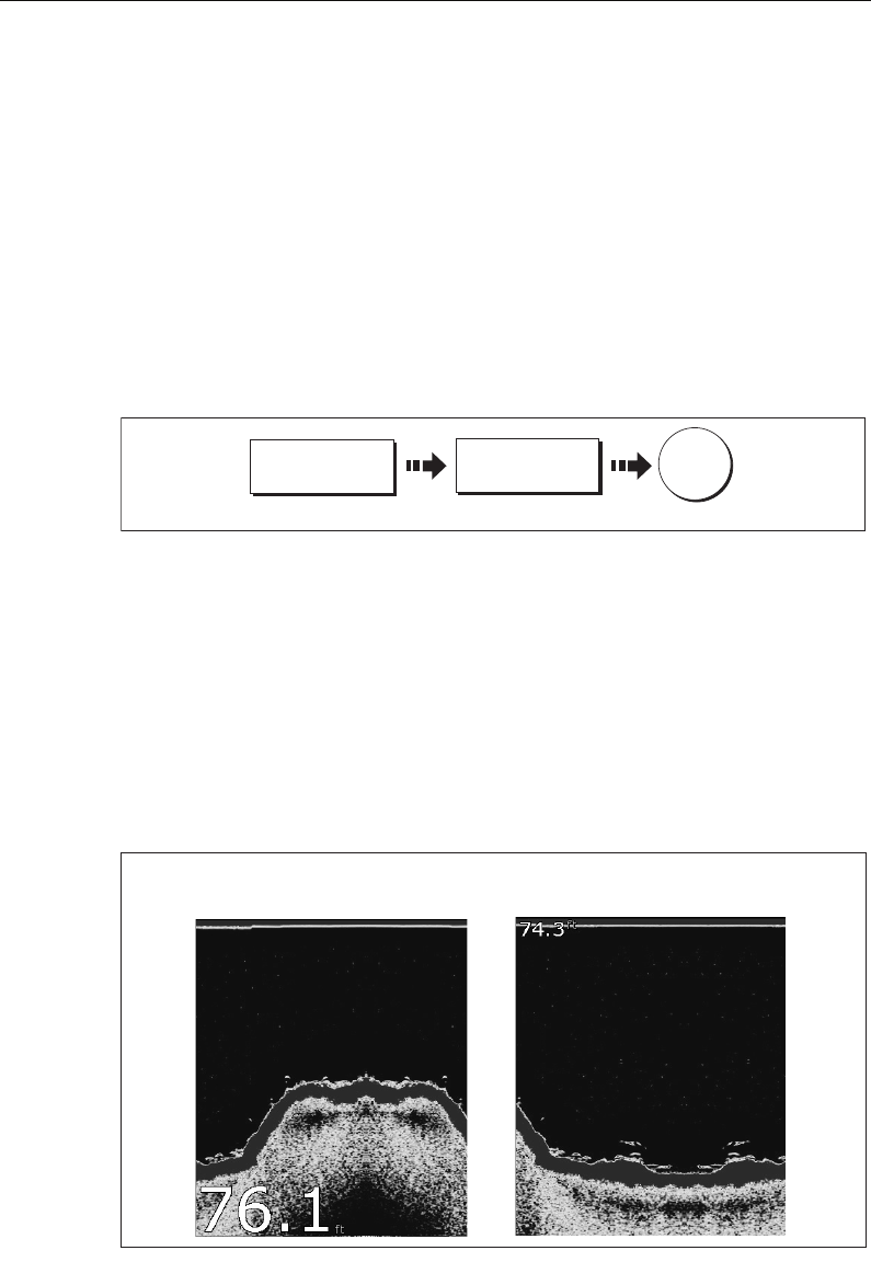
106 C-Series Display Reference Manual
Pausing the scrolling image
You can pause the display to see a ‘snapshot’ of the image. When a display is paused,
scrolling stops but the depth indication continues to be updated.Scroll pause/resume
affects the currently selected fishfinder frequency (200kHz, 50kHz or BOTH).
If you are in dual frequency mode (see
page 114
), you can pause one frequency while
the other continues to scroll. This allows you to inspect a paused image, place
waypoints or VRMs, while the other frequency continues to scroll and detect fish etc.
When in automatic frequency mode and the depth changes, the new frequency will
NOT be paused.
To pause or resume scrolling:
Changing how the depth digit is displayed
The depth under the boat is displayed in the upper or lower left hand corner of the
fishfinder window. The size of this depth digit can be adjusted or it can be switched on/
off for individual fishfinder windows.
Changing the size/position of the depth digit
You can decrease the size of the depth digit (to small or medium) and you can change
its position to the top of the screen e.g.
To change the depth digit size/position:
D8449_1
PRESENTATION... SCROLL
PAUSE RESUME
OK
Toggle as required
Depth Digit Size - LARGE
Depth Digit Position - BOTTOM
Depth Digit Size - SMALL
Depth Digit Position - TOP
D8451_1
81221_4.book Page 106 Tuesday, February 28, 2006 5:24 PM
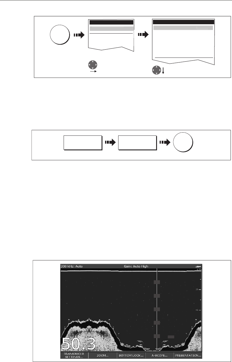
Chapter 5: Using the Fishfinder 107
Note:
No matter what size is selected, the Depth Digits will auto-shrink (when neces-
sary) to fit in the available space.
Removing/redisplaying the depth digit
To remove or redisplay the depth digit:
Note:
When multiple fishfinder windows are displayed, we recommend that the depth
digit is always displayed in at least one window.
5.5 Marking a position
You can pause the scrolling image to place a waypoint at a position or target that you
want to return to at a later date. When a waypoint is placed, its details are added to the
Waypoint List and a vertical line labelled WPT (see illustration below) is displayed on
screen. You can edit waypoints and navigate to them in the Fishfinder window.
Notes: (1)
For full details of working with waypoints, please refer to Chapter 3.
(2)
For details of how to pause the scrolling Fishfinder image, see page 106.
D8450_1
MENU
Setup
GPS Status...
Compass Setup...
Enter Fishfinder
Setup menu Select required digit size
and position
Fishfinder Setup Menu
Depth Digit Position BOTTOM
Target Depth ID OFF
Depth Lines OFF
Color Palette Copper
Scroll MANUAL
Manual Scroll Speed 100%
Fishfinder Setup..
.
Depth Digit Size LAR
GE
D8452_1
PRESENTATION... DEPTH DIGITS
ON OFF
OK
Toggle to required status
TRANSDUCER
SETTINGS… ZOOM… BOTTOM LOCK… A-SCOPE… PRESENTATION…
200 kHz: Auto Gain: Auto High
D6856-2
WPT
WPT
WPT
WPT
WPT
81221_4.book Page 107 Tuesday, February 28, 2006 5:24 PM
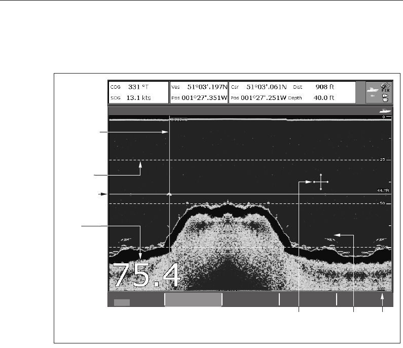
108 C-Series Display Reference Manual
5.6 Determining depths and distances of targets
The fishfinder provides various features to determine depths and distances:
•Depth reading - your current depth displayed. The size and position of this digit
can be changed via the Fishfinder display Setup menu (see
page 110
).
•Depth lines - horizontal dashed lines drawn at regular intervals to indicate the
depth from the surface. These are switched on/off via the Fishfinder Display Setup
menu (see
page 113
).
•Depth Target ID - depths noted against recognized targets. The sensitivity of
these IDs is directly linked to the Fish Alarm sensitivity; the greater the fish alarm
sensitivity, the greater the number of labelled returns. These targets are switched
on/off via the Fishfinder Display Setup menu (see
page 113
).
•Cursor depth - the depth and the distance from your boat marked by the cursor,
is indicated in the data bar at the top of the screen. This performs in a similar way to
a VRM, but without lines.
•VRMs - to indicate the distance behind your boat and the depth below of selected
objects. For further information see
page 109
.
78 78
70
69
74
63
69
73
49
48
49
74 74
200 kHz: Auto Gain: Auto High
VRM 1
ON OFF
RANGE
0.787nm
DEPTH
44.7ft
VRM marker
indicating
depth of target
VRM marker
indicating
distance
behind boat
Depth
reading
Depth line
Depth
markers
Depth
target ID
Cursor
(depth indicated
in data bar)
D6864-2
81221_4.book Page 108 Tuesday, February 28, 2006 5:24 PM
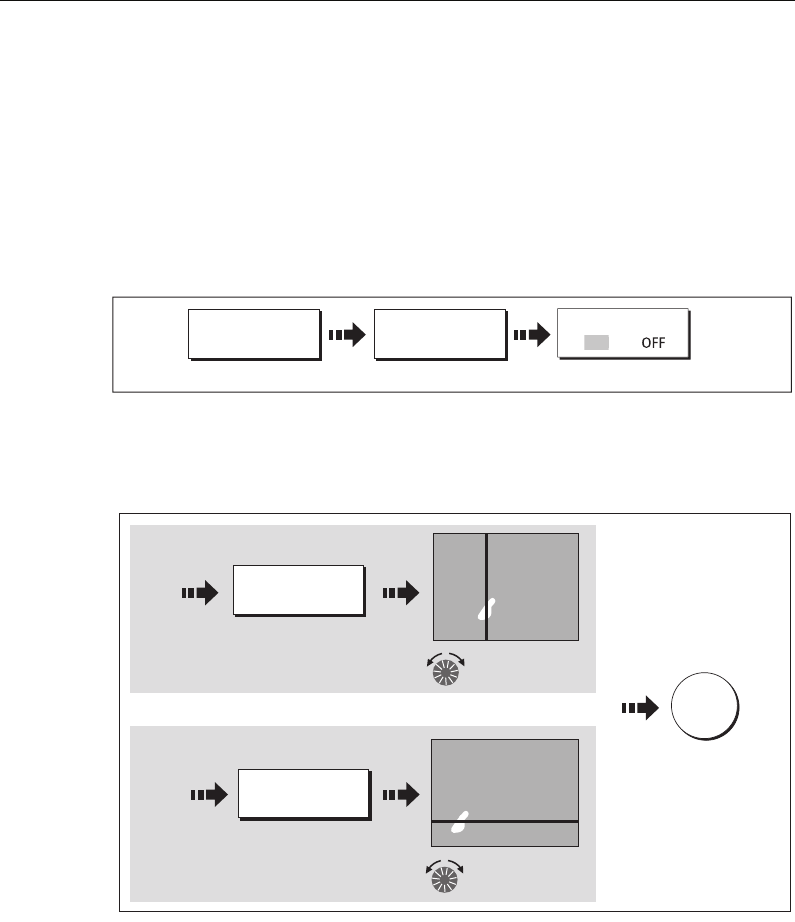
Chapter 5: Using the Fishfinder 109
Measuring using VRMs
You can use a Variable Range Marker (VRM) to determine the depth and distance-
behind-boat of an object. These markers consist of a horizontal (depth) line and a
vertical (distance-behind-boat) line; each of which are marked with the appropriate
measurement and are controlled individually.
Note:
VRMs set up in Fishfinder are unrelated to those set up in Radar.
1. Select the VRM option:
2. Pause the display to make it easier to position the VRM over an object (see page
page 106
)
3. Measure the depth and/or distance:
.
Note:
To return the marker to its previous position, press CANCEL
D8453_1
PRESENTATION... VRM...
Toggle to ON
VRM
O
N
Move range
marker over target
RANGE
49ft
Measuring distance
Measuring depth
and/or
e.g.
e.g.
Press to highlight
DEPTH
10ft
1.56nm
Move depth
marker over target
12ft
D8455_1
OK
To save
position
81221_4.book Page 109 Tuesday, February 28, 2006 5:24 PM
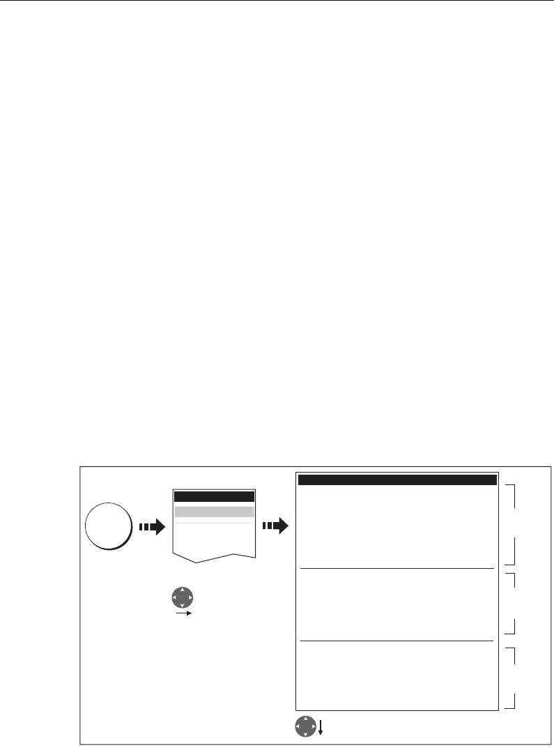
110 C-Series Display Reference Manual
5.7 Fishfinder alarms
In addition to the system alarms (see
page 187
), the following alarms can be set when
you are connected to a DSM or when the simulator is on:
•Fish Alarms - sound when a target meets the specified sensitivity level and, is
within the depth limits (if enabled). The greater the fish alarm sensitivity, the
greater the number of target image depths displayed.
•Shallow/Deep Alarms - sound when the DSM detects that the depth is less than
the shallow limit, or greater than the deep limit.
You can switch the alarms on, set the limits and specify the fish alarm sensitivity as
described on
page 188
.
5.8 Setting up your fishfinder
The set up for your fishfinder can be changed from the standard configuration to suit
your particular needs. The Fishfinder Setup Menu is divided into three sections:
• Display settings.
• Transducer settings.
• DSM settings.
To select the Fishfinder Setup Menus:
Note:
For general information on the Setup Menus, see page 183.
D8456_1
MENU
Setup
GPS Setup...
Compass Setup...
Enter Fishfinder
Setup menu
Select required function
Fishfinder Setup Menu
Depth Digit Size LARGE
Depth Digit Position BOTTOM
Target Depth ID OFF
Depth Lines OFF
Color Palette Copper
Scroll MANUAL
Manual Scroll Speed 100%
Select Transducer P65/P66
Select Speed Transducer UNKNOWN
Depth Offset (Waterline) 0.0ft
Depth Offset 100%
Temperature Offset 0.00F
Frequency Calibration...
DSM Reset...
Trip Counter Reset...
SONAR interference Rejection Auto
2nd Echo Interference Rejection OFF
Ping Rate Limite (per sec.) 30
Ping Enable
F
ishfinder Setup..
.
Display
settings
Transducer
settings
DSM
settings
81221_4.book Page 110 Tuesday, February 28, 2006 5:24 PM

Chapter 5: Using the Fishfinder 111
Display settings
The display settings provide controls to change the fishfinder image. These settings are
applied locally and will therefore only affect the individual display on which you are
working:
MENU ITEM OPTIONS
(Default in bold)
Depth Digit Size
The size of the digit indicating the depth
SMALL
MEDIUM
LARGE
Depth Digit Position
The position of the digit indicating the depth
BOTTOM
TOP
Target Depth ID
Controls whether the depth of identified targets are displayed.
N.B. The level of targets displayed is directly linked to the level of
Fish Alarm sensitivity (see
page 188
).
ON
OFF
Depth Lines
Controls whether horizontal lines indicating depth are displayed
ON
OFF
Color Palette
Choose the color palette to suit different conditions/your personal
preference.
Classic Blue
Classic Black
Classic White
Sunburst
Greyscale
Inverted Greyscale
Copper
Night Vision
Scroll
Select AUTO to vary the scroll speed in relation to your boat’s speed
or MANUAL to specify the
Scroll Speed.
MANUAL
AUTO
Manual Scroll Speed
If Scroll is set to MANUAL, specify the percentage of the normal
speed that screen should scroll at (see
page 105
for more details).
10-100%
100%
81221_4.book Page 111 Tuesday, February 28, 2006 5:24 PM

112 C-Series Display Reference Manual
Transducer Calibration
The C-Series display receives the image from a DSM which processes sonar signals
from a transducer mounted in the water. If the transducer is equipped with a speed
paddle wheel and temperature-sensing thermistor, the DSM calculates speed and
temperature. To ensure accurate readings it may be necessary to calibrate the
transducer(s) by applying offsets to depth, speed and temperature. As these settings
are held in the DSM and relate to the transducer, they are applied system-wide.
The Fishfinder Setup Menu provides the following set up options for your transducer:
MENU ITEM OPTIONS
(Default in bold)
Select Transducer
When selecting a transducer, the DSM reports to the C-Series
whether it sees a 600W or 1kW transducer. The C-Series then
allows you to select an appropriate transducer from the 600W or
1kW list.
600W detected:
P65/66
P79
P319/B117/SS555
B66V/B66VL
B744V/b744VL/SS544V
B45
1kW detected:
B256
B260
R99
Select Speed Transducer
Select the equipped speed transducer.
Note: This option is only available if the selected transducer is one
that does not include an integrated speed transducer.
NONE
UNKNOWN
B120/P120 ST 600
ST69
Depth Offset (Waterline) or (Keel)
When the offset is '0' or positive (Waterline), the offset represents
how far below the water's surface the transducer is.
When the offset is negative (Keel), the offset represents how far
below the transducer the keel is.
0 feet
+/- 9.9 feet
Speed Offset
Specify the offset to calibrate the speed transducer (if fitted).
100%
1- 200%
Temperature Offset
Specify the offset to calibrate the thermistor (if fitted).
0°F
+/- 9.9°F
Frequency Calibration...
Hides the setup menu and brings up a set of soft keys to tune the
transducer frequencies. For details, see
page 114
.
50 kHz
200 kHz
81221_4.book Page 112 Tuesday, February 28, 2006 5:24 PM

Chapter 5: Using the Fishfinder 113
DSM Setup
Certain conditions, such as a hard bottom or other vessels equipped with a fishfinder,
may affect the DSM. The following DSM Setup controls enable you to change settings
to allow for this. As they are held in the DSM, they are applied system-wide.
Any changes that you make to the set up are saved when you power off the digital
sounder module (DSM) except for the following:
MENU ITEM OPTIONS
(Default in bold)
DSM Reset...
Restore all settings on the DSM to factory default. When per-
forming a DSM Reset, it is normal to briefly loose connection
with the DSM.
YES
NO
Trip Counter Reset...
Resets the Trip Counter of the DSM.
YES
NO
SONAR Interference Rejection
Removes spikes caused by other fishfinder-equipped vessels
AUTO
LOW
MEDIUM
HIGH
2nd Echo Interference Rejection
Minutely adjusts the ping rate according to the 2nd echo level.
Results in better sensitivity of the image.
OFF
LOW
HIGH
Ping Rate Limit (per sec.)
Provides a speed limiter; it is useful to adjust the ping rate to
suit local conditions. For example, the ping rate may be too fast
when there is a hard bottom in shallow water.
26 pings per second
5 to 30 pings per second
Ping enable
The sonar ping is normally enabled. It can be disabled. This is
useful when other equipment is being tested, or if someone is
diving beneath the boat.
Disabled
Enabled
Type Function Reverts to
Soft keys Gain AUTO (automatic)
Auto Gain Mode MED (medium)
TVG AUTO (automatic)
Range AUTO (automatic)
Range Shift 0
Power AUTO (automatic)
Setup Menu Ping Speed Limit 26
Ping Enable Enabled
81221_4.book Page 113 Tuesday, February 28, 2006 5:24 PM

114 C-Series Display Reference Manual
5.9 Other settings affecting the fishfinder image
The system automatically adjusts the following settings in order to optimize the
fishfinder image:
• Operating frequency.
• Gain modes (Gain, Color Gain, TVG)
• Power setting.
They should not ordinarily require adjustment. You can however make adjustments
manually if required.
Operating frequency modes
The operating frequency is indicated in the status bar. You can choose to either set the
frequency to automatic (default) or manual.
Automatic frequency
When operating in automatic frequency, your DSM automatically changes the
frequency from 200 kHz to 50 kHz as your depth increases and from 50kHz to 200 kHz
as your depth decreases. This mode is useful for automatically searching for the
bottom and is the normal mode of operation.
Manual frequency
Manual frequency allows you to manually set the system to either a single or dual
frequency mode:
Single frequency mode
This mode sets the transducer to ping at a single frequency:
•50 kHz - scans a wide area and penetrates water well. Use this setting when you
are in deep water and the DSM is locked onto a shallow target e.g. very large shoal
of fish or you are in very shallow water (<30 feet) and you need to see better fish
targets (wider cone angle),or:
•200 kHz - scans a narrow area but produces more detail. Use this setting when you
are in deep water and the 200 kHz signal is so strong that you want to retain this
higher resolution picture. It is good for finding fish that are near the bottom or close
together.
To select a single frequency:
T
Note:
Changing the frequency in a single fishfinder window will automatically change
all other fishfinder windows to that frequency.
D7353-2
Toggle to required
frequency
FREQUENCY
AUTO MAN
FREQ MODE
SINGLE DUAL
FISHFINDER
SETTINGS...
SELECTED FREQ
200 50 BOTH
81221_4.book Page 114 Tuesday, February 28, 2006 5:24 PM
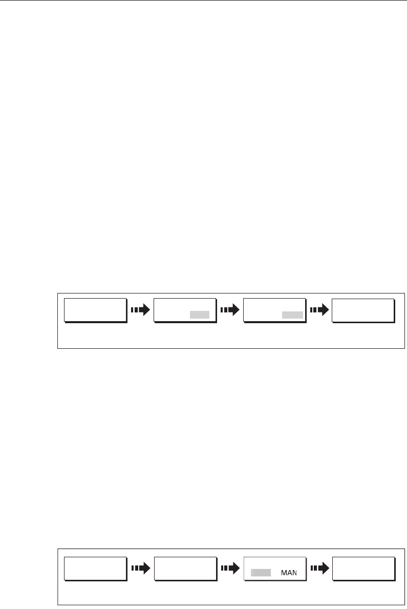
Chapter 5: Using the Fishfinder 115
Dual frequency mode
In dual frequency mode the DSM pings at the same rate but alternates between 200
kHz and 50 kHz. This allows you to select the required frequency(s) - 50kHz, 200 kHz or
BOTH for each individual fishfinder window. Combine this mode with the zoom,
bottom lock and A-scope functions to customize each fishfinder window to meet your
particular requirements or fishing conditions. For example, when you are in deeper
water you can set one fishfinder application to 200 kHz and another to 50kHz. Display
the 50 kHz in normal mode to show full bottom detail and a long history. This will give
you an overview of the current fishing conditions. Display the 200 kHz window in full-
pan zoom to view the top of the water column in very high detail and see fish
swimming near the surface. In a third fishfinder application, select BOTH to split the
window and display a high resolution image (200 kHz) and a wider cone (50kHz)
simultaneously. Using these settings covers all possibilities and ensures that nothing is
missed.
Note:
When BOTH (default) is selected, any changes that you make to the zoom, bot-
tom lock, A-scope etc. will be applied to both images within that window.
To select the dual frequency(s) for the active fishfinder window:
Gain modes
You can make various adjustments to the gain modes if required:
•Gain mode.
•Auto gain.
• Color gain.
•TVG.
Note:
In addition to the controls described in this section, the Fishfinder Setup options
allow you to adjust the Interference Rejection, 2nd Echo Interference Rejection and
Ping Rate Limit. These options are described on page 110.
Auto gain modes
D9059_1
Toggle to required
frequency
FREQUENCY
AUTO MAN
FREQ MODE
SINGLE DUAL
FISHFINDER
SETTINGS...
SELECTED FREQ
200 50 BOTH
FISHFINDER
SETTINGS...
D7357-2
GAIN MODE
AUT
O
GAIN... AUTO GAIN
LO MED HIGH
Toggle to required
setting
81221_4.book Page 115 Tuesday, February 28, 2006 5:24 PM
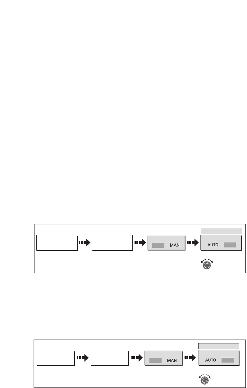
116 C-Series Display Reference Manual
The gain, or sensitivity, of the display adjusts background noise by varying the echo
strength for display. The value of the GAIN control determines the strength above
which echoes are displayed. There are three AUTO GAIN modes:
•Low is ideal for viewing fishfinder images with a minimum of background noise as
you are cruising to your fishing spot. Only the strongest echoes are displayed.
•Medium is a slightly higher gain setting that displays more detailed echoes as you
are trolling. This is the default mode.
•High gives the best details of the targets you have located but also displays the
most background noise and surface clutter. This is suitable when you are fishing.
With all of these modes, the DSM will automatically adjust the Gain setting for current
conditions and adjust separately for each frequency. Any adjustments made apply to
all windows using that frequency.
Manually adjusting the gain modes
If necessary you can set the gain controls manually. The new values remain set even
when you switch off the display and are applied to both the active window and any
other fishfinder windows displaying that frequency.
Manual Gain Mode
This should be set high enough to see fish and bottom detail but without too much
background noise. Generally, a high gain is used in deep and/or clear water; a low gain
in shallow and/or murky water.
Color Gain
This sets the lower limit for the strongest echo color. All echoes with a signal strength
above this value are displayed in the strongest color. Those with a weaker value are
divided equally between the remaining colors. Setting a low value produces wide band
for the weakest color, but a small signal band for the other colors; setting a high value
gives a wide band for the strongest color, but a small signal band for the other colors.
D7548-2
FISHFINDER
SETTINGS... GAIN... GAIN MODE
100
GAIN MODE
adjust setting
Press to highlight
soft key
Toggle to manual and
MA
N
AU
T
O
FISHFINDER
SETTINGS...
D7358-2
COLOR GAIN
GAIN...
100
COLOR GAIN
adjust setting
Press to highlight
soft key
Toggle to manual and
MA
N
AUTO
81221_4.book Page 116 Tuesday, February 28, 2006 5:24 PM
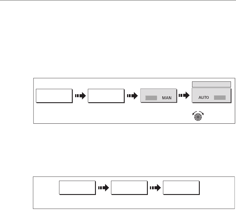
Chapter 5: Using the Fishfinder 117
TVG (Time Varied Gain)
The TVG (Time Variable Gain) reduces the clutter by varying the gain throughout the
water column. This function is useful for reducing the appearance of ‘noise’. Increasing
the TVG value increases the maximum depth to which TVG is applied. Decreasing it
reduces the maximum depth. A low TVG value has little effect on gain in shallow
water; a high value decreases the gain in shallow water so that only the strongest
echoes are displayed. TVG has no effect in Fishfinder Simulator Mode.
Gain adjust (200/50)
When the SELECTED FREQ is set to BOTH (see
page 115
), the GAIN ADJUST soft key is
enabled to allow you to select the frequency that the gain controls affect.
To adjust this gain setting:
Note:
Gain adjustment for individual frequencies is only available when the selected
frequency is set to BOTH.
Adjusting the power setting
The Power control provides adjustment of the transducer signal.
Auto
This is the default setting. When it is selected the DSM automatically determines the
required power setting based on the current depth, speed, and (bottom) signal
strength.
Manual
If you wish to manually adjust the power to suit current conditions, you can adjust the
power level between 0 and 100%, in 10% increments. Lower power levels are
normally used in depth ranges less than 8 ft. (2.4 m) and higher power levels are
typically selected for depths greater than 12 ft. (3.7 m).
Note:
When the power level setting is changed there is a short delay while the new
setting takes effect.
FISHFINDER
SETTINGS...
D7359-2
GAIN... TVG
100
TVG
adjust setting
Press to highlight
soft key
Toggle to manual and
MA
N
AU
T
O
FISHFINDER
SETTINGS...
D8457-1
GAIN ADJUST
200 50
GAIN...
Toggle to the
required frequency
81221_4.book Page 117 Tuesday, February 28, 2006 5:24 PM
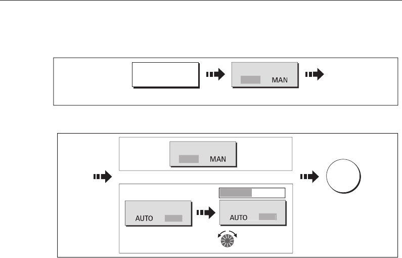
118 C-Series Display Reference Manual
To adjust the Power Setting:
1. Select the power setting function:
2. Select the power setting mode and adjust as necessary:
D8460_1
FISHFINDER
SETTINGS...
POWER
Press to highlight
AU
T
O
D8461_1
Select required mode
POWER
MA
N
POWER
MAN
POWER
AUT
O
Or
50
Adjust level as
required
OK
81221_4.book Page 118 Tuesday, February 28, 2006 5:24 PM

Chapter 6: Using the Radar 119
Chapter 6:Using the Radar
6.1 Introduction
This chapter describes the basics of radar and the things that can affect your radar
picture. It then shows you how to use your radar and its various functions including:
• Changing orientation and motion mode.
• Getting the best radar picture.
• Measuring distances and bearings.
• Collision avoidance using Guard Zones, MARPA and AIS.
• Using waypoints to mark positions.
• Setting up the radar display.
• Radar alarms.
•View AIS data.
6.2 What is radar?
Radio Detection And Ranging (RADAR) is something that is in use all around us,
although it is normally invisible. One of the most common uses of radar at sea is to
detect the presence of objects, known as ‘targets’ at a distance, and if they are moving,
detect their speed.
This chapter of the Reference manual provides the information and instructions to
enable you to start using the radar so that you know what is around you and use the in-
built Mini Automatic Radar Plotting Aid (MARPA) functions to help in collision
avoidance.
Until you are familiar with interpreting the radar display, every opportunity should be
taken to compare the radar screen patterns with visual targets, such as other boats,
buoys and coastal structures. You should practise harbor and coastal navigation
during daylight hours and in clear weather conditions.
Detecting targets
Radar works by transmitting radio pulses, then detecting reflections of these pulses
(echoes) from objects in the area and displaying the reflections as targets on your
display.
81221_4.book Page 119 Tuesday, February 28, 2006 5:24 PM
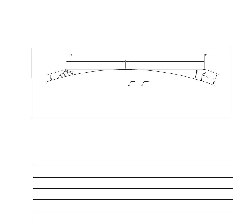
120 C-Series Display Reference Manual
Maximum radar range
Maximum radar range is essentially line-of-sight, so is limited by the height of the
scanner and the height of the target as illustrated below:
The table below shows typical maximum radar ranges for various radar antenna
heights and target heights. Remember that although the radar horizon is greater than
the optical horizon, the radar can only detect targets if a large enough target is above
the radar horizon.
Factors impairing a radar picture
Not all radar echoes are produced by valid targets. Spurious echoes may be caused by:
• Side lobes.
• Indirect echoes.
• Multiple echoes.
• Blind sectors.
• Sea, rain or snow clutter.
• Interference.
Through observation, practice, and experience, you can generally detect these
conditions very quickly and use the radar controls to minimize them.
Antenna height (m) Target height (m) Maximum range (nm)
337.7
3 10 10.9
538.8
5 10 12.0
a1a2
Earth
h
H
Cliff
Radar
D1643-3
Rmax
Rmax = 2.23 ( h + H )
Rmax
h
H
maximum radar range
radar antenna height
target height
in nautical miles
in metres
in metres
Rmax = radar horizon of antenna (
a
1) + radar horizon of target (
a
2)
81221_4.book Page 120 Tuesday, February 28, 2006 5:24 PM
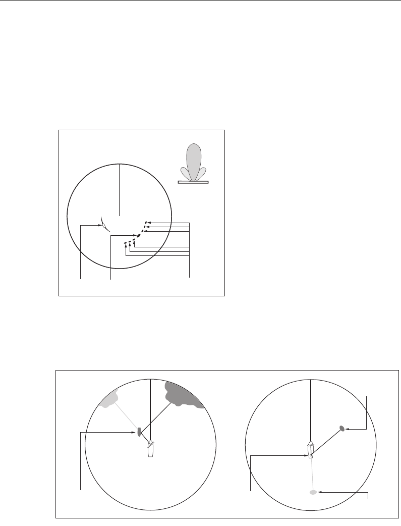
Chapter 6: Using the Radar 121
Side lobes
Side lobe patterns are produced by small amounts of energy from the transmitted
pulses that are radiated outside the narrow main beam.
The effects of side lobes are most noticeable with targets at short ranges (normally
below 3 nm), and in particular with larger objects. Side lobe echoes form either arcs on
the radar screen similar to range rings, or a series of echoes forming a broken arc.
Indirect echoes
There are several types of indirect echoes or ghost images. These sometimes have the
appearance of true echoes, but in general they are intermittent and poorly defined.
True echo Side echoes
Main lobe
Antenna
Arc
Side
lobe
Side
lobe
D1638-4
False echo
Passing
ship
True echo
D1641-4
True echo
False echo
Mast
or funnel
81221_4.book Page 121 Tuesday, February 28, 2006 5:24 PM
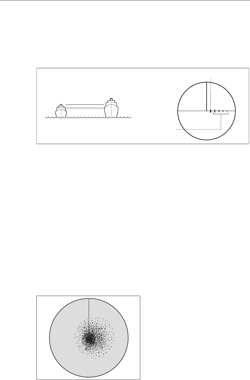
122 C-Series Display Reference Manual
Multiple echoes
Multiple echoes are not very common but can occur if there is a large target with a
wide vertical surface at a comparatively short range. The transmitted signal will be
reflected back and forth between the target and your own ship, resulting in multiple
echoes, displayed beyond the range of the true target echo, but on the same bearing.
Blind sectors
Obstructions such as funnels and masts near the radar antenna may obstruct the radar
beam and cause radar shadows or ‘blind sectors’. If the obstruction is relatively
narrow, there will be a reduction of the beam intensity, though not necessarily a
complete cut-off. However, for wider obstructions there may be a total loss of signal in
the shadow area. There may also be multiple echoes which extend behind the
obstruction. Blind sector effects can normally be minimized by careful selection of the
scanner site prior to installation.
Sea clutter
Radar returns from waves around the vessel can clutter the centre of the radar picture,
making it difficult to detect real targets. Such ‘sea clutter’ usually appears as multiple
echoes on the display at short range scales, and the echoes are not repetitive or
consistent in position. With high winds and extreme conditions, echoes from sea
clutter may cause dense background clutter in the shape of an almost solid disc.
D1642-3
True echo
Multiple echoes
D3968-4
81221_4.book Page 122 Tuesday, February 28, 2006 5:24 PM
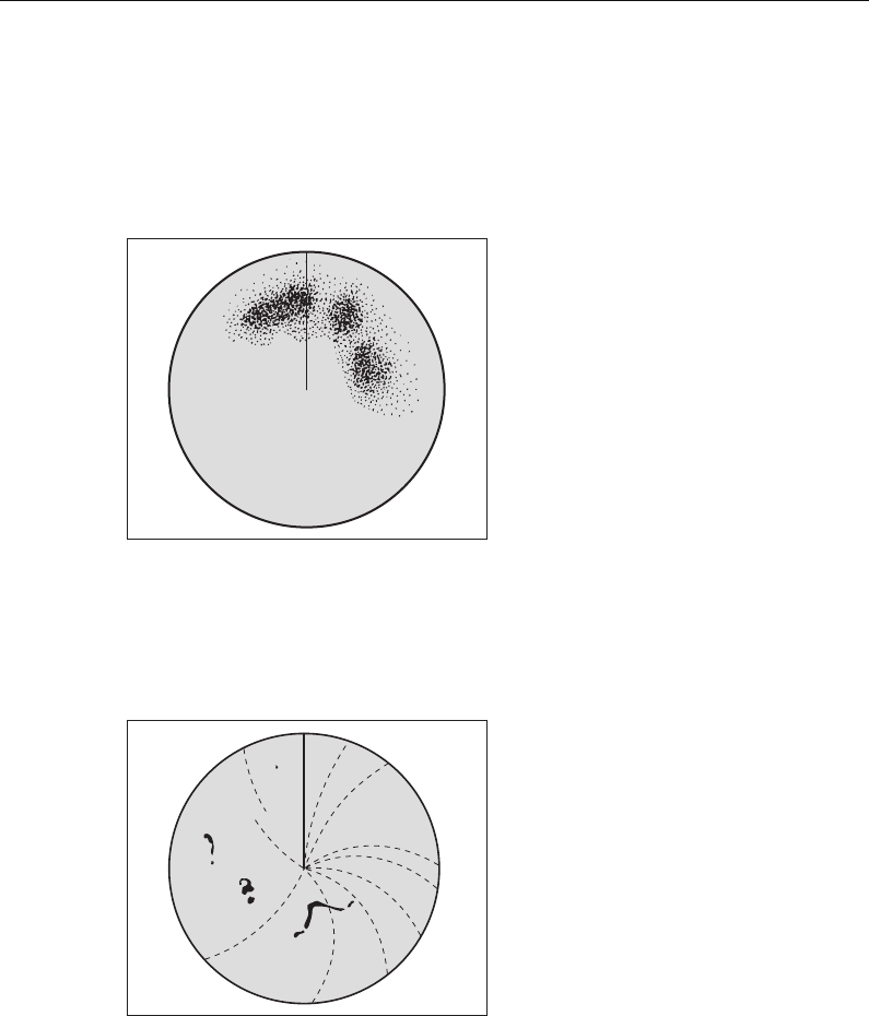
Chapter 6: Using the Radar 123
Rain or snow clutter
The radar can see echoes from rain or snow. Returns from storm areas and rain squalls
consist of countless small echoes that continuously change size, intensity and position.
These returns sometimes appear as large hazy areas, depending on the intensity of the
rainfall or snow in the storm cell.
Interference
When two or more radar-equipped vessels are operating within range of each other
mutual radar interference can occur. This usually appears as a spiral of small dots from
the display centre This type of interference is most noticeable at long ranges.
D3967-4
D6601-2
81221_4.book Page 123 Tuesday, February 28, 2006 5:24 PM
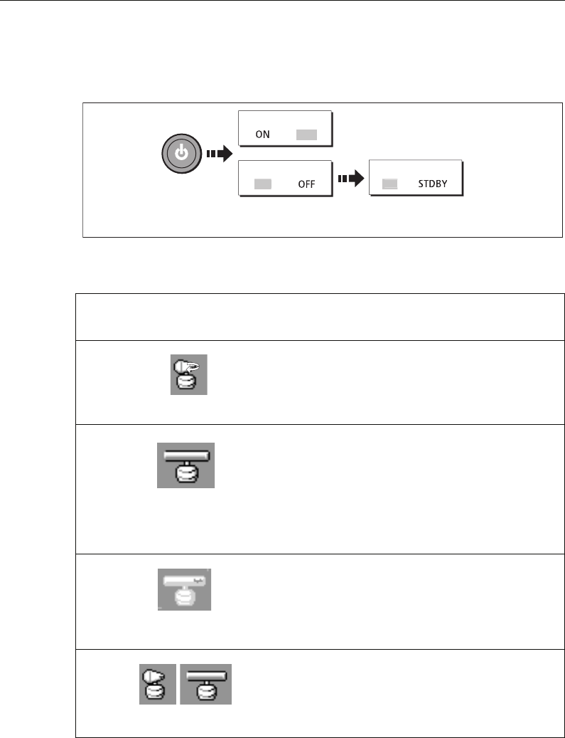
124 C-Series Display Reference Manual
6.3 Powering on/off the various scanner operating modes
To control the power to the radar:
The scanner icon in the data bar indicates the chosen status and is described as:
Note:
When an open array antenna is fitted, the system stops the antenna in the for-
ward facing position when Standby mode is selected.
Radar
Mode
Radar status
icon Status description/use
Transmit
(TX)
Scanner on and transmitting.
When SCANNER set to ON, select this mode to activate scan-
ner. This is the usual mode of operation.
Standby
(STDBY)
Scanner on but not transmitting and antenna not
rotating.
Antenna does not rotate, the scanner does not transmit and
the radar data is removed from the screen. This is a power
save mode used when radar not needed for short time peri-
ods. When you return to transmit mode, the magnetron does
not need to warm up. This is the default mode.
Off Scanner powered off
When radar not required but display in use for other applica-
tions e.g. chart.
When selected, system countdowns - during this time you
cannot re-power the scanner.
Timed
transmit
Scanner switches between on/transmitting &
standby mode
Power save mode when constant use of radar not required.
To set up this option, see
page 148
SCANNER
RADAR
O
F
F
SCANNER
O
N TX
Select required
operating mode
Switch scanner ON
or OFF
D8397_1
D7440-1
(Rotating icon)
D6894-2
(static icon)
D7441-1
(grayed-out icon)
D7442-1
(rotating/static icon)
81221_4.book Page 124 Tuesday, February 28, 2006 5:24 PM
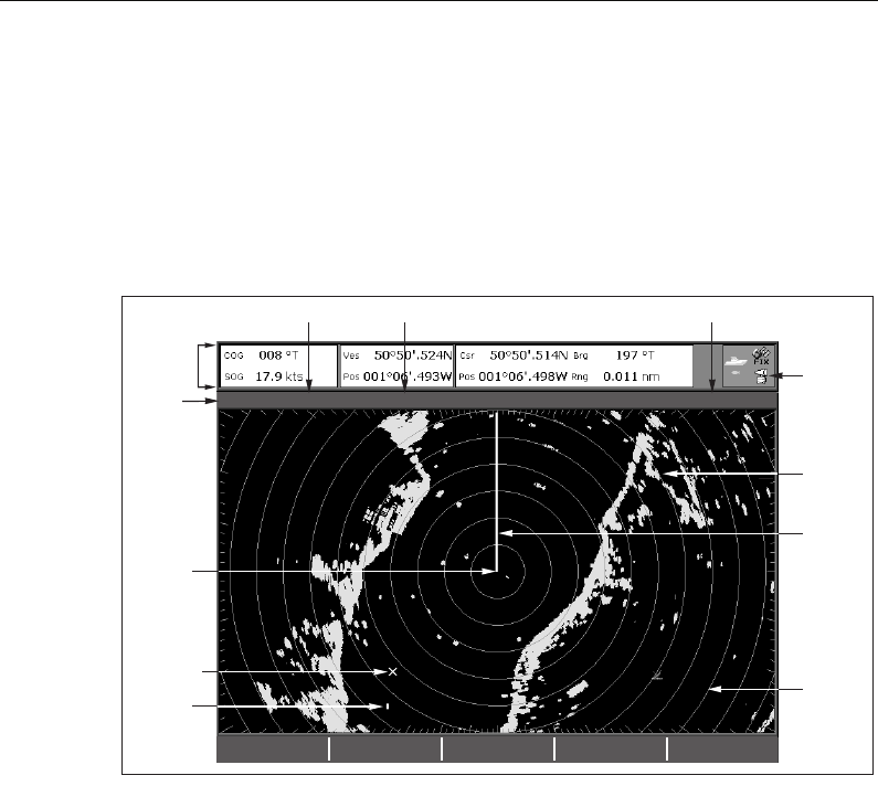
Chapter 6: Using the Radar 125
6.4 The radar picture
You will need heading and position data for full functionality of your radar. A fast
heading sensor is also needed for operation of MARPA and can maximize the
performance of radar/chart overlay.
With your radar scanner connected and the radar in transmit mode, the radar picture,
provides a map-like representation of the area in which the radar is operating e.g.
Typically, your boat’s position is at the centre of the display, and its dead ahead bearing
is indicated by a vertical heading line, known as the Ship’s Heading Marker (SHM).
On-screen targets may be large, small, bright or faint, dependent on the size of the
object, its orientation and surface. Strongest target returns are displayed in yellow
with weaker returns in two shades of blue. Be aware that the size of a target on screen
is dependent on many factors and may not necessarily be proportional to its physical
size. Nearby objects may appear to be the same size as a distant larger objects.
With experience, the approximate size of different objects can be determined by the
relative size and brightness of the echoes. You should bear in mind that:
The size of each on-screen target is affected by:
• The physical size of the reflecting object.
• The material from which the object is made. Metallic surfaces reflect signals better
than non-metallic.
• Vertical objects such as cliffs reflect signals better than sloping ones such as sand-
banks
• High coastlines and mountainous coastal regions can be observed at longer radar
ranges. Therefore, the first sight of land may be a mountain several miles inland
3nm Head-Up Relative Motion Rings ½nm
VRM/EBL... GAIN... PRESENTATION...
TARGET
TRACKING...
ENHANCE
ECHOES...
D6803-3
Orientation
Data bar
Surface
vessel
Waypoint
Ship's
heading
marker
Radar
status
icon
Range
ring
Land-
mass
Boat's
position
Range
Motion mode Range ring spacing
81221_4.book Page 125 Tuesday, February 28, 2006 5:24 PM

126 C-Series Display Reference Manual
from the coastline. Although the coastline may be much nearer, it may not appear
on the radar until the vessel is closer to shore.
• Some targets, such as buoys and small boats, can be difficult to discern, because
they do not present a consistent reflecting surface as they bob and toss about in the
waves. Consequently, these echoes tend to fade and brighten and at times, to dis-
appear momentarily.
• Buoys and small boats often resemble each other, but boats can often be distin-
guished by their motion.
6.5 Marking a position on the radar screen
You can mark a position by using a waypoint. Waypoints are positions marked on the
screen as a reference or destination point and are stored in the Waypoint list. They can
also be used to build routes and assist in passage planning.
Waypoints are placed on the radar screen via the WPTS/MOB button in the same way
as they are placed on a chart.
You can edit waypoints and navigate to waypoints in the radar window
For full details on using waypoints and passage planning see
Chapter 3:Working with
Waypoints
and
Chapter 4:Using the Chart
.
6.6 Changing what you see in the radar window
The radar screen can be tailored to your particular needs. You can:
• Change how the radar is orientated (see
page 126
).
• Change where your boat is positioned (motion mode) in relation to the radar (see
page 128
).
• Show or hide waypoints (see
page 42
).
• Show or hide range rings (see
page 130
).
• Change the bearing mode for EBLs (see
page 130
).
• Show AIS targets.
Setting the orientation of the radar
The orientation of the radar refers to the relationship between the radar and the
direction that you are travelling in. There are three orientation modes to choose from:
•Head up.
• North up.
• Course up.
These orientation modes are used in conjunction with motion mode (see
page 128
) to
control how your boat and radar relate to one another and how they are displayed on
81221_4.book Page 126 Tuesday, February 28, 2006 5:24 PM
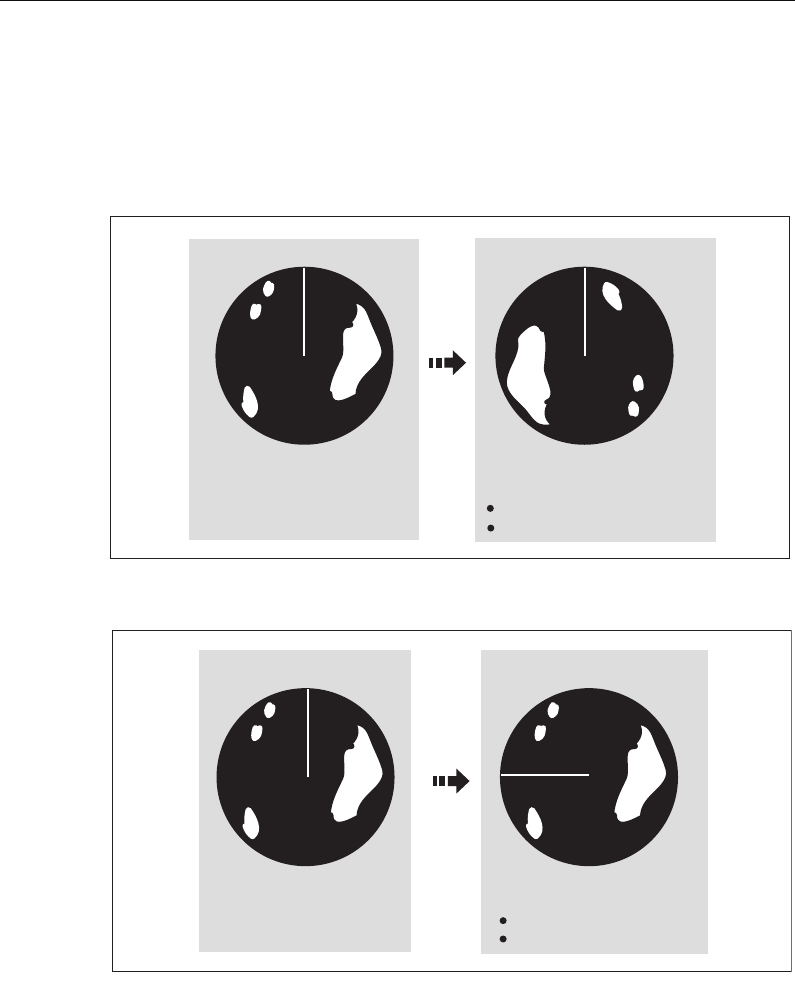
Chapter 6: Using the Radar 127
screen. Any changes that you make to the orientation of the radar are retained when
you switch off.
Head Up (H-UP)
This is the default mode for the radar application.
North Up (N-UP)
Notes: (1) If heading data becomes unavailable whilst in this mode, a warning
message will be shown, the status bar indicates North-Up in brackets
and the radar uses 0° heading in relative motion. When heading data
becomes available once more, North-Up mode is reinstated.
(2) It is not possible to select Head Up mode when the motion mode is set
to True.
Ship's Heading Market (SHM)
(indicating the boat's current
heading) is upwards
As your boat's heading changes:
SHM fixed upwards
Radar picture rotates accordingly
N
N
e.g:
D8398_1
N
e.g:
True north at top
N
D8399_1
As your boat's heading changes:
Radar picture fixed (north up)
SHM rotates accordingly
81221_4.book Page 127 Tuesday, February 28, 2006 5:24 PM
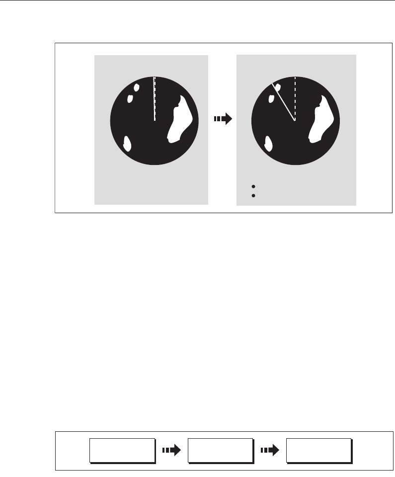
128 C-Series Display Reference Manual
Course Up (C-UP)
If you select a new course, the picture will reset to display the new course upwards.
The reference used for Course-Up depends upon the information available at a given
time. The system always prioritizes this information in the following order.:
1. Bearing from origin to destination, i.e. intended course.
2. Locked heading from an Autopilot.
3. Bearing to waypoint.
4. Instantaneous heading.
Note:
If heading data becomes unavailable whilst in this mode, a warning message
will be shown, the status bar indicates the Course Up in brackets and the radar uses 0°
heading in relative motion. When heading data becomes available once more, Course-
Up mode is reinstated.
To select the orientation mode:
The selected motion mode is displayed in the status bar.
Setting the motion mode
The motion mode controls the relationship between the radar and your boat. There are
two modes:
•Relative motion.
• True motion.
The selected motion mode is displayed in the status bar. The default setting is relative
motion with zero offset
Current course upwards
NN
D8400_1
As your boat's heading changes:
Radar picture fixed
SHM rotates accordingly
e.g:
D6592-2
RADAR MODE &
ORIENTATION…
PRESENTATION… ORIENTATION
H-UP N-UP C-UP
81221_4.book Page 128 Tuesday, February 28, 2006 5:24 PM
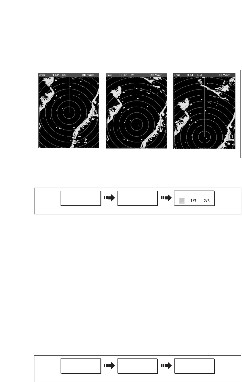
Chapter 6: Using the Radar 129
Relative motion (RM) with optional vessel offset
When the motion mode is set to Relative, the position of your boat is fixed on the
screen and all the targets move relative to the boat.
You can specify whether the boat is fixed in the centre of the window (0 offset) or offset
by 1/3 or 2/3 to increase the view ahead i.e.
The default mode for the radar application is Relative with zero offset.
To change the vessel offset:
Note:
If no position data is available, the status bar shows the motion mode in brack-
ets.
True Motion (TM)
When the motion mode is set to True, fixed radar targets maintain a constant position
and moving vessels (including your boat) travel in true perspective to each other and to
fixed landmasses on the screen. As the boat’s position approaches the edge of the
screen, the radar picture is automatically reset to reveal the area ahead of the boat.
Notes: (1)
If heading and position data become unavailable when True motion is se-
lected, a warning message will be shown, the mode will revert to relative
motion and be noted in the status bar in brackets e.g. (TM)
(2)
It is not possible to select True Motion when the orientation is set to Head
Up.
To change the motion mode:
D6842-2
0 offset 2/3 offset
1/3 offset
D8805_1
RADAR MODE &
ORIENTATION…
PRESENTATION… VESSEL OFFSET
Toggle as required
0
D6838-2
RADAR MODE &
ORIENTATION…
PRESENTATION… MOTION MODE
TM RM
Toggle as required
81221_4.book Page 129 Tuesday, February 28, 2006 5:24 PM
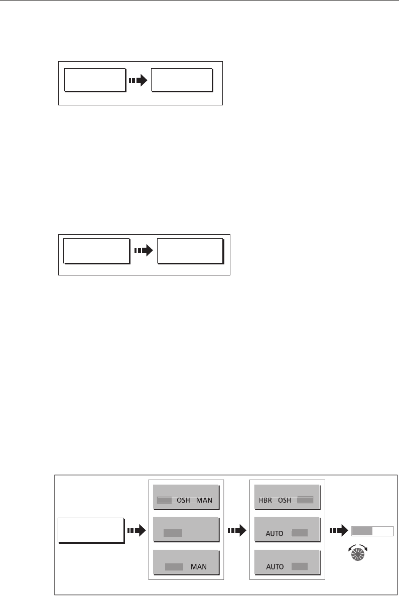
130 C-Series Display Reference Manual
Showing or hiding the range rings
To turn the range rings on/off:
Changing the bearing mode for EBLs
The default bearing mode for EBLs is relative to your vessel’s heading. If heading data
is available, you can set the bearing mode to be relative (REL), magnetic/true (M/T).
When M/T is selected, the EBL bearings will be expressed as either true or magnetic
dependant on the equipment connected. The current EBL bearing is expressed on both
the radar screen EBL label and on the ADJUST EBL soft key.
To change the EBL reference:
6.7 Getting the best picture
You can improve the quality of the radar picture by using:
• The gain controls - sea, gain, tune, FTC and rain.
• The target display controls - interference rejection, expansion, wakes.
Using the GAIN functions
The gain function reduces the effects of false echoes and clutter.
For the best results Raymarine recommends that you retain the AUTO default setting.
You can however adjust these settings manually if required.
Manually adjusting the gain modes
The sea, gain and tune controls can all be adjusted manually if necessary:
o
Note:
The new values remain set even when you switch off the display and are applied
to both the active window and any other radar windows.
PRESENTATION
D6897-2
RANGE RINGS
OFF ON
Toggle as required
PRESENTATION
D6898-2
EBL REFERENCE
M/T REL
Toggle as required
GAIN
D8406_1
SEA
H
BR
Press to highlight Toggle to manual (MAN)
TUNE
GAIN
AUTO MAN
A
U
T
O
SEA
MAN
TUNE
GAIN
Adjust
level as
required
MA
N
MA
N
50
81221_4.book Page 130 Tuesday, February 28, 2006 5:24 PM

Chapter 6: Using the Radar 131
Sea
Radar echoes from waves around your boat can clutter the centre of the radar picture,
making it difficult to detect real targets (see
page 122
).
Adjusting the sea mode will reduce this clutter for up to 5 nautical miles (depending on
wave and sea conditions) from your boat. This has the effect of reducing the sea echoes
to intermittent small dots whilst small targets remain visible and persistent. Gain
levels further from your boat remain unchanged. There are three sea gain modes:
•HBR (Automatic Harbor mode) - this takes account of the effects of land clutter so
that small target are not lost. It should be used when you are in harbor or in close
proximity to land.
•OSH (Automatic Offshore mode) - the system continually calculates the required
level of sea clutter control.
•MAN (Manual mode) - this enables you to select the sea clutter level and then
adjust the settings to ensure that all close small targets are visible. On short range
scales, do not set the SEA control so high that all clutter is removed, since this could
stop you seeing echoes from close targets. The acuteness of the sea clutter curve is
set up in the Radar Setup menu (see
page 149
). Manual sea clutter mode should be
used in conjunction with the GAIN function (described below).
Gain
The gain function makes the radar picture clearer by changing the sensitivity of radar
reception.
•For long ranges - select a sensitivity level that gives a slight speckle in the back-
ground. Be careful not to set the gain too low, or you may miss weak or small tar-
gets.
•For shorter ranges - reduce the gain slightly to reduce the speckle and therefore
improve target definition.
Note:
If you set the GAIN to MAN (manual), you should check it every time you change
the range scale.
Tune
The tune function is used to fine tune the receiver in the scanner for maximum target
returns on the display.
Auto mode
In AUTO mode, the radar tunes itself automatically on all range scales. This is the
default and it is recommended that you leave the TUNE function in
AUTO mode, to ensure that the radar receiver is always tuned to
receive the maximum signal.
81221_4.book Page 131 Tuesday, February 28, 2006 5:24 PM

132 C-Series Display Reference Manual
Manual (MAN) mode
If you do set the TUNE function to MANUAL, you will need to adjust it about 10 minutes
after you have turned on the radar, since the required setting will change after the
magnetron has warmed up. You should adjust the control to obtain the maximum
signal strength (indicated by the eight step horizontal bar.). If you cannot tune the
radar successfully, refer to the Installation Guide.
FTC
You can use the Fast Time Constant (FTC) function to remove areas of clutter at a
distance from your boat or to distinguish between two very close echoes on the same
bearing, which may otherwise merge and appear as one echo
When the FTC function is turned up, only the leading edge of large (rain clutter) echoes
is shown, while the effect on smaller (ship) echoes is only slight. As the receiver is less
sensitive, and background noise and fill-in returns from land and other large targets
reduced, you should turn the FTC function down when its use is not required. Since
storm cells are usually visible for long distances due to their extreme altitude, you may
wish to leave them displayed so that you can observe the location of bad weather.
Note:
Use FTC in conjunction with the RAIN function to obtain the best picture.
Rain
Your radar detects echoes from rain or snow. The strength of these echoes is dependent
upon the altitude, range, density and size of the snow flakes or rain droplets and will
appear on screen (see
page 123
) as countless small echoes continuously changing
size, intensity and position.
Turning the RAIN clutter function on suppresses the bulk effect of rain returns from
around your boat, so that detection of actual targets is made easier.
Using the enhance echoes functions
You can improve visibility with the enhance echoes function.
Interference Rejection
ON
The interference rejection function, which is normally left switched on, automatically
reduces any mutual radar interference when two radar equipped vessels are operating
within range of each other (see
page 123
).
To change the interference rejection setting:
81221_4.book Page 132 Tuesday, February 28, 2006 5:24 PM
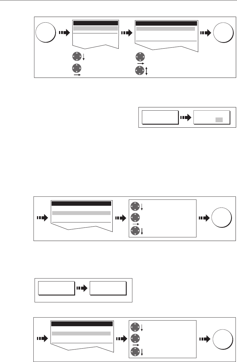
Chapter 6: Using the Radar 133
Note:
This menu can also be selected by pressing and holding INT. REJECT.
OFF
If you wish to detect the presence of other
radars in the vicinity:
Expansion
The expansion function allows you to either override the pulse length or to give larger
returns so targets are easier to see:
Overriding the pulse length
To override the pulse length:
1. Select the Radar Setup Menu:
2. Set the magnification level for target expansion to HIGH:
Larger returns
To alter the processing to give larger returns:
1. Select the Radar Setup Menu:
2. Set the magnification level for target expansion to LOW:
Note:
Selecting this option may compromise target resolution.
D8414_1
MENU
Setup
GPS Status...
Compass Setup...
Highlight Radar
Setup
Select Radar Setup
R
adar Setup..
.
Select NORMAL or HIGH
Select Interference Reject
Radar Setup Menu
Interference Reject NORMAL
Target Expansion LOW
Wakes Period 1 min
OK
ENHANCE
ECHOES...
INT REJECT
ON OFF
D8416_1
Press and hold
ENHANCE
ECHOES...
D8417_1
EXPANSION
ON OFF
Select HIGH
D8419_1
Radar Setup Menu
Enter Target Expansion option
Select Target Expansion
Interference Reject NORMAL
Target Expansion HIGH
Wakes Period 1 min
OK
Press and hold
ENHANCE
ECHOES...
D8417_1
EXPANSION
ON OFF
D8420_1
Radar Setup Menu
Interference Reject NORMAL
Target Expansion LOW
Wakes Period 1 min OK
Select HIGH
Enter Target Expansion option
Select Target Expansion
81221_4.book Page 133 Tuesday, February 28, 2006 5:24 PM
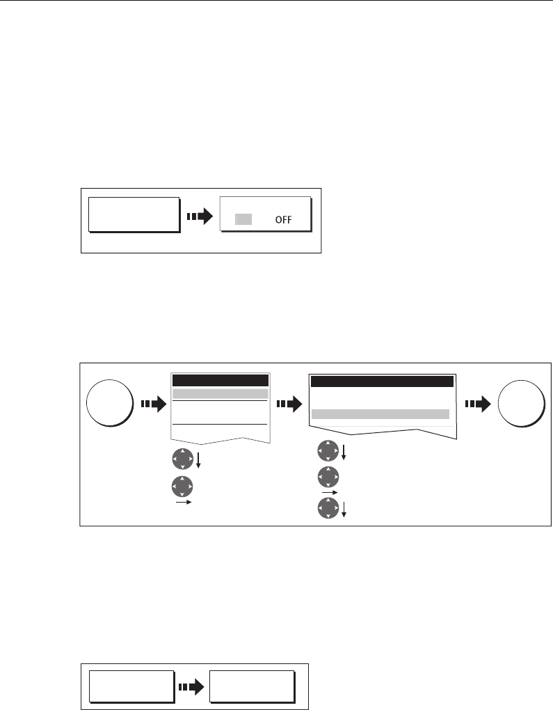
134 C-Series Display Reference Manual
Wakes
When the wakes function is switched on, you can see the direction and speed of
moving targets relative to your boat. A target is displayed in yellow and as the signal
diminishes with time it is shown in paler shades of blue.
Displaying wakes
To switch on the wakes function:
Specifying the wake period
You can select via the Radar Setup Menu, whether these wakes are shown for periods
of 10 seconds, 30, seconds, 1 minute, 5 minutes or 10 minutes.
To specify the wake period:
Note:
You can also enter the Radar Setup Menu by pressing and holding the WAKES
soft key.
Removing wakes
When the currently displayed wakes are no longer required they can be remove from
your screen:
ENHANCE
ECHOES...
WAKES
D8421_1
O
N
Toggle to ON
Radar Setup Menu
Interference Reject NORMAL
Target Expansion LOW
Wakes Period 1 min
OK
D8422_1
Select Wakes Period
Select wakes period
Highlight Wakes Period
MENU
Highlight Radar
Setup
Select Radar Setup
Setup
Radar Setup...
GPS Status...
Compass Setup...
System Setup...
ENHANCE
ECHOES...
D8423_1
CLEAR WAKES
81221_4.book Page 134 Tuesday, February 28, 2006 5:24 PM
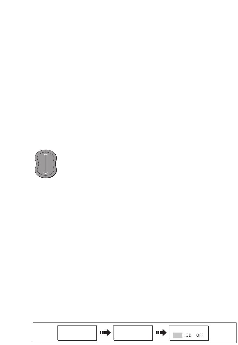
Chapter 6: Using the Radar 135
6.8 Changing the displayed range
You can zoom in or out to view your radar picture at varying scales. The scale is
measured from the centre to the top of the window and is displayed in the left-hand
corner of the status bar.
The scale you will need is dependent upon where you are navigating and the level of
detail that you wish to see:
•Short range scales - provide greater detail of radar echoes close to the vessel,
and are most suited for use as you approach coastlines, habors or other vessels in
the area. The shortest range scale available is 1/8 nautical miles (or the equivalent
in the chosen unit).
•Long range scales - provide the best overview of the vessel’s relationship to
landmasses, weather fronts and large ship targets in or beyond the field of vision.
The longest range scale available is between 24 and 72 nautical miles (or the equiv-
alent in the chosen unit) depending upon the scanner fitted.
The range of the radar is adjusted by pressing the RANGE button.
Press IN to decrease the range scale or ‘zoom in’.
Press OUT to increase the range scale or ‘zooms out.
Each press of the button changes the range by one setting. Pressing and holding the
button will change the range quickly in the required direction.
Radar range and chart scale synchronization
The chart application includes an option to synchronize the radar range and chart
scale.
When synchronization is switched on:
• The radar range in all radar windows, changes to match the chart scale.
• ‘Sync’ is indicated in the top left-hand corner of the chart window.
• If you change the radar range, in any radar window, all synchronized chart views
change scale to match.
• If you change the scale of a synchronized chart window, all radar windows change
range to match.
With a chart window active, set the radar range synchronization:
Note:
Radar range synchronization is not available when the chart motion mode is set
to Autorange.
D6585-2
RANGE
IN
OUT
D7578-3
CHART MODE AND
ORIENTATION…
CHART SYNC
PRESENTATION… RDR
81221_4.book Page 135 Tuesday, February 28, 2006 5:24 PM
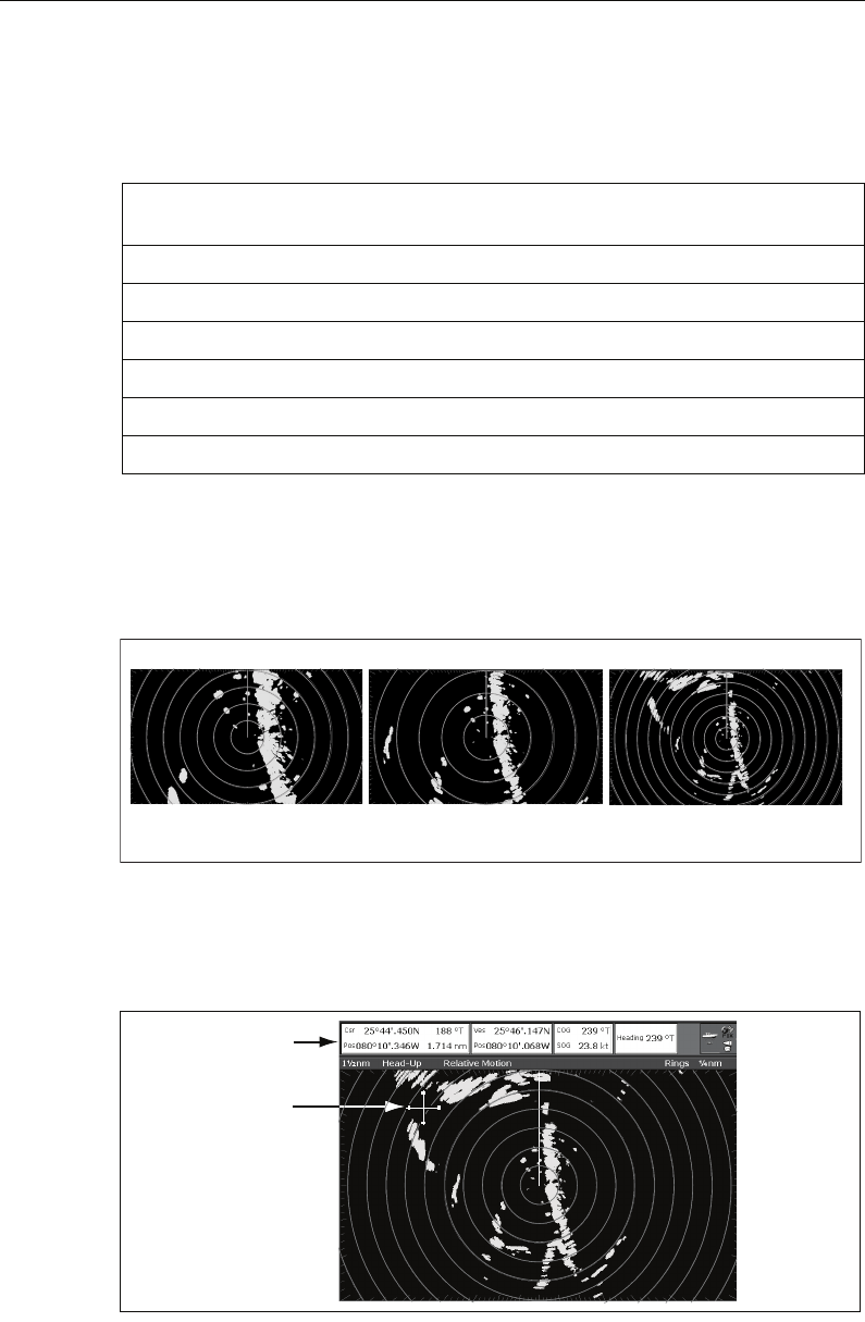
136 C-Series Display Reference Manual
6.9 Measuring distances, ranges and bearings
When you are using the radar application, you can measure distances, ranges and
bearings in a variety of ways. These options are detailed in the table below:
... Using the range rings
Use the range rings to gauge the approximate distances between points. Range rings
are concentric circles displayed on the screen and centred from your boat at pre-set
distances. The number and spacing of the rings changes as you range in and out.
... Using the cursor
To measure the bearing and range from your boat to a specified target, move the
cursor to the appropriate position on the screen.
Note:
If cursor data is not shown, refer to page 180.
Functions Distances
between points
Range from
your boat Bearings
Range Rings Yes (approx.) Yes (approx.) -
Cursor - Yes Yes
Variable Range Markers (VRMs) - Yes -
Electronic Bearing Lines (EBLs) - - Yes
Floating VRMs Yes - -
Floating EBLs Yes
Range -
1
/
4
nm
Range rings -
1
/
8
nm apart
Range -
3
/
4
nm
Range rings -
1
/
4
nm apart
Range - 1
1
/
2
nm
Range rings -
1
/
4
nm apart
D8407_1
e.g.
Bearing and range from
your vessel to cursor
D8402_1
Cursor
81221_4.book Page 136 Tuesday, February 28, 2006 5:24 PM
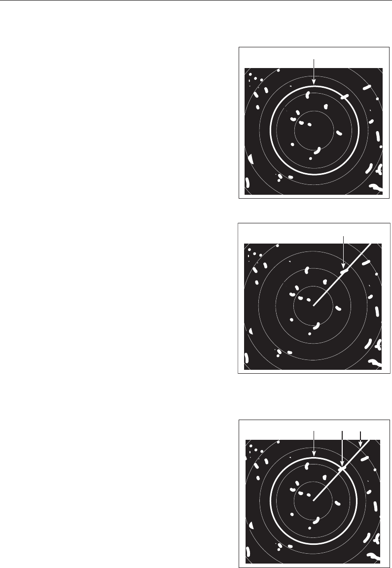
Chapter 6: Using the Radar 137
... Using VRMs and EBLs
What is a VRM?
A Variable Range Marker (VRM) is a circle
centred on your vessel’s position and fixed
with respect to the heading mode.
When this circle is adjusted to align with a
target, its range from your boat is
measured and displayed on the ADJUST
VRM soft key.
The data is also displayed if you select the
VRM with the cursor.
What is an EBL?
An Electronic Bearing Line (EBL) is a line
drawn from your boat to the edge of the
window.
When this line is rotated to align with a
target, its bearing relative to your boat’s
heading is measured and displayed on the
ADJUST EBL soft key.
The data is also displayed if you select the
EBL with the cursor.
Note:
To change the EBL reference from relative to magnetic or true, see page 130.
Combined VRM and EBL
A VRM and an EBL can be combined to
measure both the range and the bearing
of the specified target.
D8408_1
VRM
D8425_1
EBL
D8403_1
EBL
VRM Target
81221_4.book Page 137 Tuesday, February 28, 2006 5:24 PM
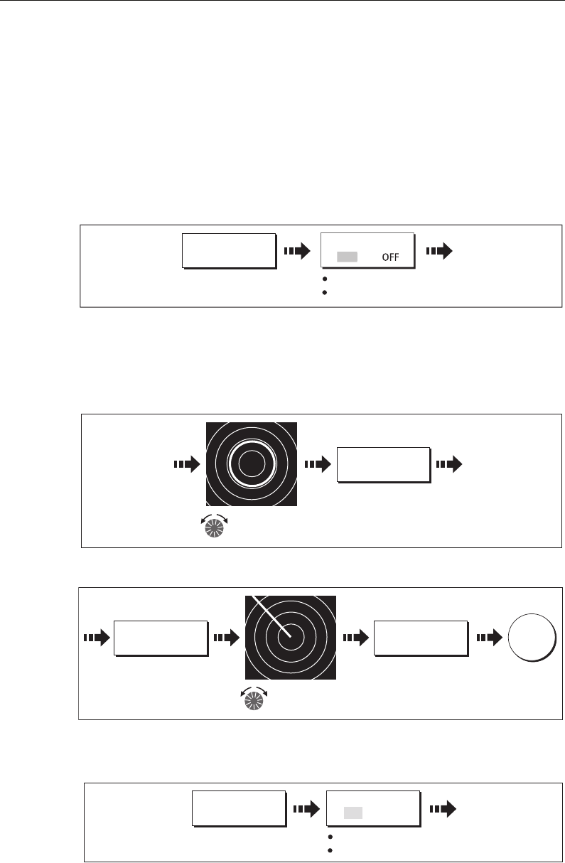
138 C-Series Display Reference Manual
Tracking a target with a VRM/EBL
You will be able to tell which way the target is traveling by watching how it moves in
relation to the EBL. If it continues traveling directly along the EBL, it shows that it is on
a possible collision course with your boat - take the appropriate action.
Creating a VRM and/or EBL
To use VRMs and EBLs to tell you the range and bearing of a target:
1. Select the VRM/EBL 1option:
Note:
The first VRM/EBL will be placed at a location of 1/3 of the current range and
030° relative to your boat’s head. If this setting is adjusted, the display will retain the
adjustments and use them when the VRM/EBL is next turned on.
2. Adjust the VRM to the required size:
3. Adjust the EBL to the required angle:
4. Save the adjustment and remove control from the VRM/EBL:
5. To place a second VRM/EBL if required:
VRM/EBL...
D8404_1
Toggle to ON
Adjust VRM highlighted
VRM/EBL 1
O
N
D8405_1
Adjust VRM to
required size
ADJUST VRM
0.838nm
Distance from your
boat to VRM displayed
on soft key.
D8427_1
Adjust EBL to
required angle
Angle to starboard/
port displayed on
soft key.
ADJUST EBL
xxx0
ADJUST EBL
410P
OK
SET UP VRM/EBL
2
D8428_1
Toggle to ON
Adjust VRM highlighted
VRM/EBL 2
ON OFF
81221_4.book Page 138 Tuesday, February 28, 2006 5:24 PM
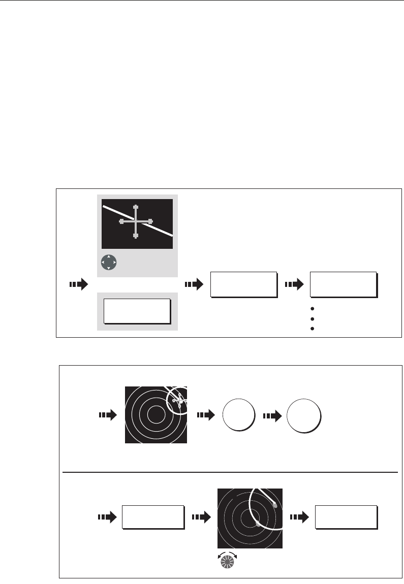
Chapter 6: Using the Radar 139
... Using floating VRMs/EBLs
You can use the VRM/EBL float function to measure the range and bearing between
any two points on the radar screen. This function allows you to move the VRM/EBL
centre away from your boat’s position and onto a target. You can then change the
radius of the VRM to determine the distance between two points and change the angle
of the EBL, relative to its new origin, to obtain the bearing.
Floating a VRM/EBL
1. Create the VRM/EBL as described previously.
2. Select the floating option:
3. Measure the range between two points:
4. Measure the bearing between two points:
Position cursor
over VRM/EBL
VRM/EBL
Or:
D8429_1
Soft key highlighted
VRM/EBL highlighted
Cursor centered
FLOATING EBL... ADJUST FLOAT
VRM/EBL...
Move VRM over
2nd target
Range between
1st & 2nd target
on soft key
ADJUST VRM
xxxnm
ADJUST VRM
2.6nm
Define first point:
Define second point:
D8430_1
Move VRM/EBL center
over first target
To save and
remove
highlight
OK
To access
soft keys
OK
81221_4.book Page 139 Tuesday, February 28, 2006 5:24 PM
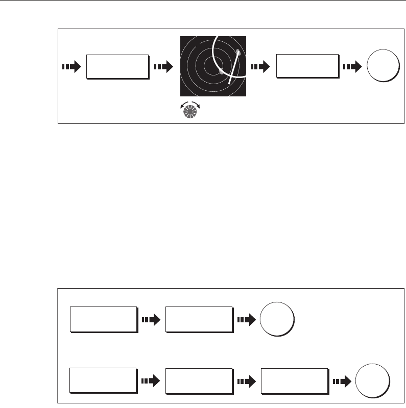
140 C-Series Display Reference Manual
5. If required, you can float a second VRM/EBL:
i. Press SET UP VRM/EBL 2.
ii. Toggle the VRM/EBL 2 to ON.
iii. Repeat steps 1 to 8 above.
Unfloating a VRM/EBL
To unfloat VRM/EBLs and return them to the central position:
1. Select the VRM/EBL option.
2. Unfloat VRM/EBL 1 or 2:
6.10 Using radar to avoid a collision
Your radar includes numerous functions to help you avoid a collision. You can:
• Assess how far away a target is and its bearing (VRMs/EBLs).
• Set an alarm to trigger when a target is within a specified zone (Guard Zones).
• Display detailed information on tracked targets (MARPA).
• Display the identity of other vessels and if broadcasted, their voyage information
(AIS).
• Display the range and bearing of a target.
Guard Zones
Guard zones are fixed with respect to the SHM, moving as it moves. They also move if
the centre is offset or the range scale is changed, so that the pre-marked area is
D8431_1
Bearing between
1st & 2nd target
on soft key
ADJUST VRM
1900
Move EBL over
2nd target
ADJUST EBL
xxx0
To save &
remove
highlight
OK
D8432_1
To unfloat VRM/EBL 1:
FLOATING EBL... CENTER
OK
To unfloat VRM/EBL 2:
FLOATING EBL... CENTER
SET UP VRM/EBL
2
OK
81221_4.book Page 140 Tuesday, February 28, 2006 5:24 PM
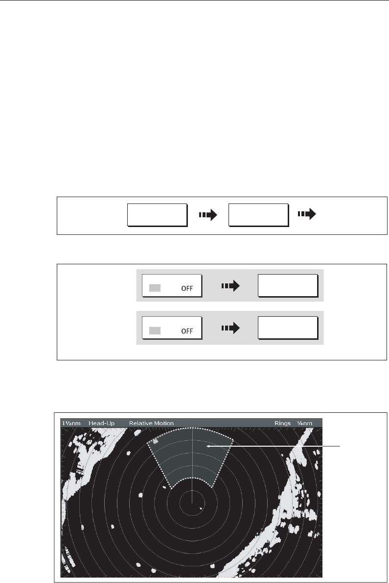
Chapter 6: Using the Radar 141
maintained. A guard zone only operates when the whole zone is displayed on the
screen. An audible alarm sounds to alert you when a target enters the zone.
Guard zones are inactive for 10 seconds after being placed or re-sized, to avoid
inappropriate alarms whilst they are being positioned.
You can set up guard zones to be either sector zones or 360° (circular) zones. Your
radar can be set up using one or two zones.
You can adjust the sensitivity of the guard zone via the Alarms Setup Menu described
on
page 188
.
To set up a guard zone:
1. Select the guard zone option:
2. Select Zone 1 or 2:
You can now select the guard zone to be either a sector or a circular zone.
Sector guard zones
To set up a sector guard zone:
MONITOR IN
ZONES...
TARGET
TRACKING
D6834-2
ZONE 1 SET UP ZONE 1
D8433_1
O
N
ZONE 2 SET UP ZONE 2
O
N
Toggle to ON
Or
6nm Head-Up Relative Motion Rings 1nm
D6815_3
Sector
Guard Zone
81221_4.book Page 141 Tuesday, February 28, 2006 5:24 PM
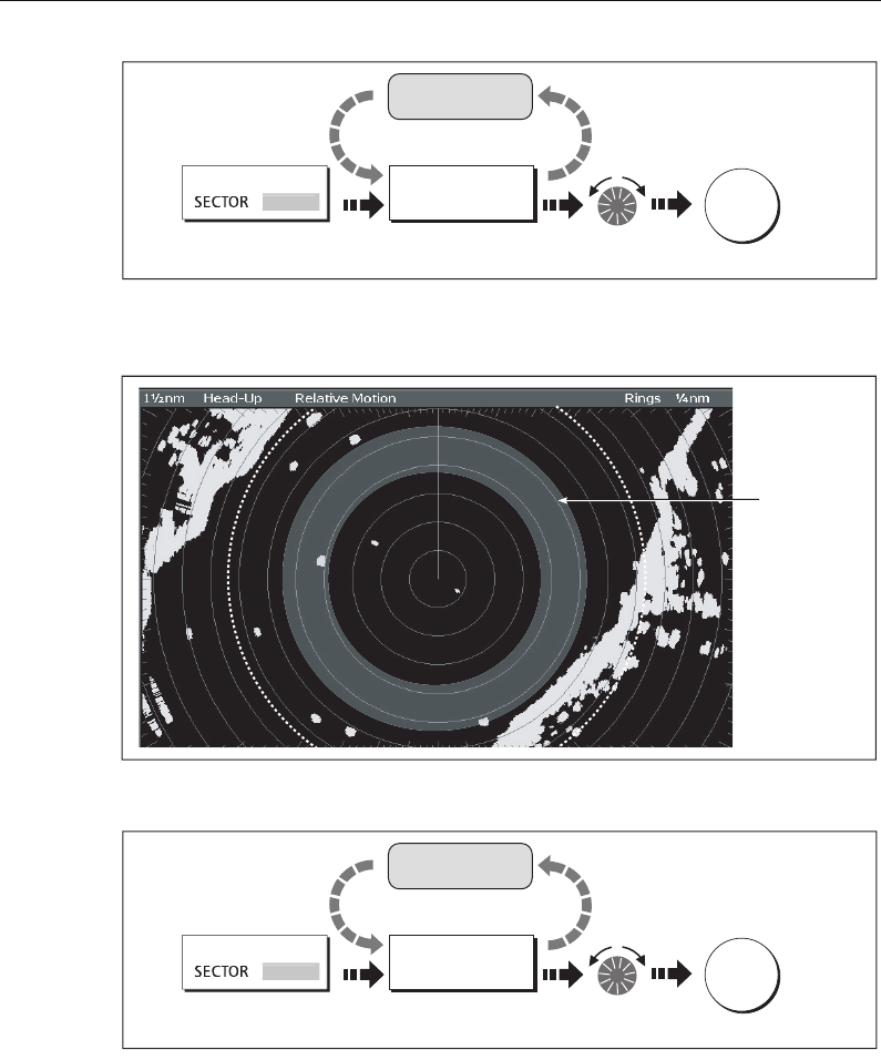
142 C-Series Display Reference Manual
Circular guard zone
To set up a circular guard zone:
D6761_3
ZONE SHAPE
CIRCL
E
SET INNER
xx.xx nm
Press to highlight Set inner limit
for guard zone
OK
Repeat for
other settings
6nm Head-Up
D6832-2
Circular
Guard Zone
D6761_3
ZONE SHAPE
CIRCL
E
SET INNER
xx.xx nm
Press to highlight Set inner limit
for guard zone
OK
Repeat for
other settings
81221_4.book Page 142 Tuesday, February 28, 2006 5:24 PM

Chapter 6: Using the Radar 143
MARPA
SAFETY NOTICES
MARPA can improve collision avoidance when used wisely. It is the User’s
responsibility to exercise common prudence and navigational judgements.
There are conditions where acquiring a target may become difficult. These same
conditions may be a factor in successfully tracking a target. Some of the conditions are:
• The target echo is weak. The target is very close to land, buoys or other large targets.
• The target or your own ship is making rapid manoeuvres.
• Choppy sea state conditions exist and the target is buried in excessive sea clutter or
in deep swells.
• Choppy sea state conditions exist yielding poor stability; own boat’s heading data
is very unstable.
• Inadequate heading data.
Symptoms of such conditions are that acquisition is difficult and the MARPA vectors
are unstable; the symbol wanders away from the target, locks on to another target or
changes to a lost symbol target.
If any of these conditions are present, acquisition and tracking may need to be re-
initiated or, in some cases be impossible to maintain. Improving the quality of the
heading data will reduce the effect of the other conditions.
Introduction to MARPA
You can use the Mini Automatic Radar Plotting Aid (MARPA) functions for target
tracking and risk analysis. MARPA improves collision avoidance by obtaining detailed
information for up to 10 automatically tracked targets and provides continuous,
accurate and rapid situation evaluation.
MARPA automatically tracks acquired targets, calculates target bearing and range,
speed and course, Closest Point of Approach (CPA), and Time to Closest Point of
Approach (TCPA).
Each target tracked can be displayed with a CPA graphic which shows the target
vessel, course and speed (as a vector) and indicates the CPA. The calculated target
data can also be shown on your screen. Each target is continually assessed and an
audible alarm is sounded if a target becomes dangerous, or is lost.
Effective MARPA operation is dependant on accurate own-ship’s heading and speed.
Speed Over Ground (SOG) and Course Over Ground (COG) information are required to
show true target course and speed. The better the quality of the heading and speed
data, the better MARPA will perform. MARPA will function without SOG and COG in
relative mode. For the best heading data a Raymarine SMART heading sensor or a
gyro-stabilized autopilot is required.
81221_4.book Page 143 Tuesday, February 28, 2006 5:24 PM
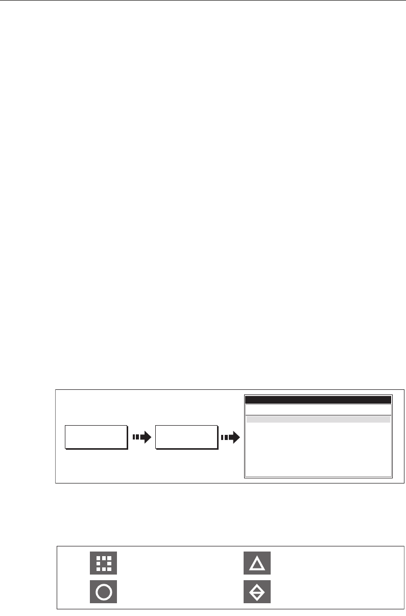
144 C-Series Display Reference Manual
How is a risk assessed?
Each target is monitored to see if it will be within a certain distance from your boat
within a certain time. If so, the target is designated as dangerous and an audible
warning is sounded along with an on-screen warning being shown. The target symbol
changes to the dangerous target symbol and flashes to indicate that it is a dangerous
target. Pressing the appropriate soft key will silence the alarm and remove the
warning.
If a target is lost, either because the MARPA software has lost contact with it, or
because it has moved out of range, an audible alarm is sounded and an on-screen
warning appears. The on-screen symbol will change to the target lost symbol. Pressing
the appropriate soft key will silence the alarm and remove the on-screen warning and
the target lost symbol.
How far from my boat does MARPA work?
MARPA target acquisition is only available at radar range scales of up to 12nm,
although tracking continues at all ranges.
If you change to a smaller range scale, targets may be beyond the range of your
scanner and will be lost. In such cases, an on-screen warning will indicate that the
target is off-screen.
What happens to target data?
All MARPA targets are stored in a MARPA database list which shows the following
information:
Target display
Each target is displayed as a symbol which indicates its status:
D6811_2
MARPA LIST...
TARGET
TRACKING
ID Bearing Range
True
Course
True
Speed CPA TCPA
022
o
T
025
o
T
0.000nm
0.000nm
180
o
T
180
o
T
0.0kts
0.0kts
0.000nm
0.000nm
00h00m00s
00h00m00s
MARPA LIST
1
2
D7542_2
Dangerous target
Safe target
Target being acquired
Lost target
81221_4.book Page 144 Tuesday, February 28, 2006 5:24 PM
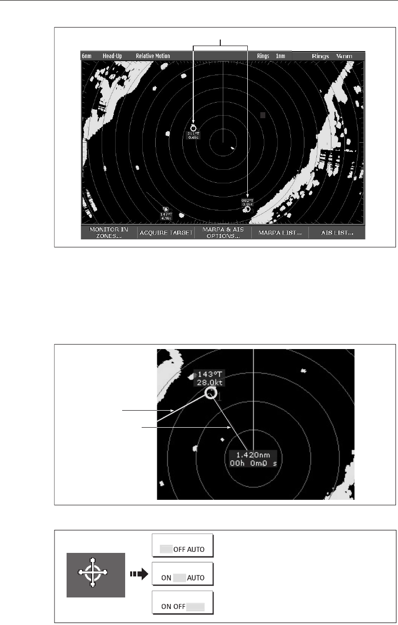
Chapter 6: Using the Radar 145
CPA graphics
CPA graphics show vectors for your vessel and a selected target. A vector is a line on-
screen showing the predicted courses of your vessel and the selected target if you both
remain on your present course. These vectors vary in length due to boat speed and
vector length set in the MARPA Setup menu.
To display the CPA graphic and associated soft keys:
MARPA targets
D6810_4
D9008_1
Vector
CPA graphic
39
D9009_1
CPA GRAPHIC
CPA GRAPHIC
CPA GRAPHIC
1810T
17.1 kt
Move cursor over
target
O
N
O
FF
AUT
O
ON - The CPA graphic will be displayed for as long as
the target is being tracked.
OFF - No CPA graphic is shown.
AUTO - When you place the cursor over any part of a
MARPA symbol, the CPA graphic is displayed. This is
the default setting.
81221_4.book Page 145 Tuesday, February 28, 2006 5:24 PM
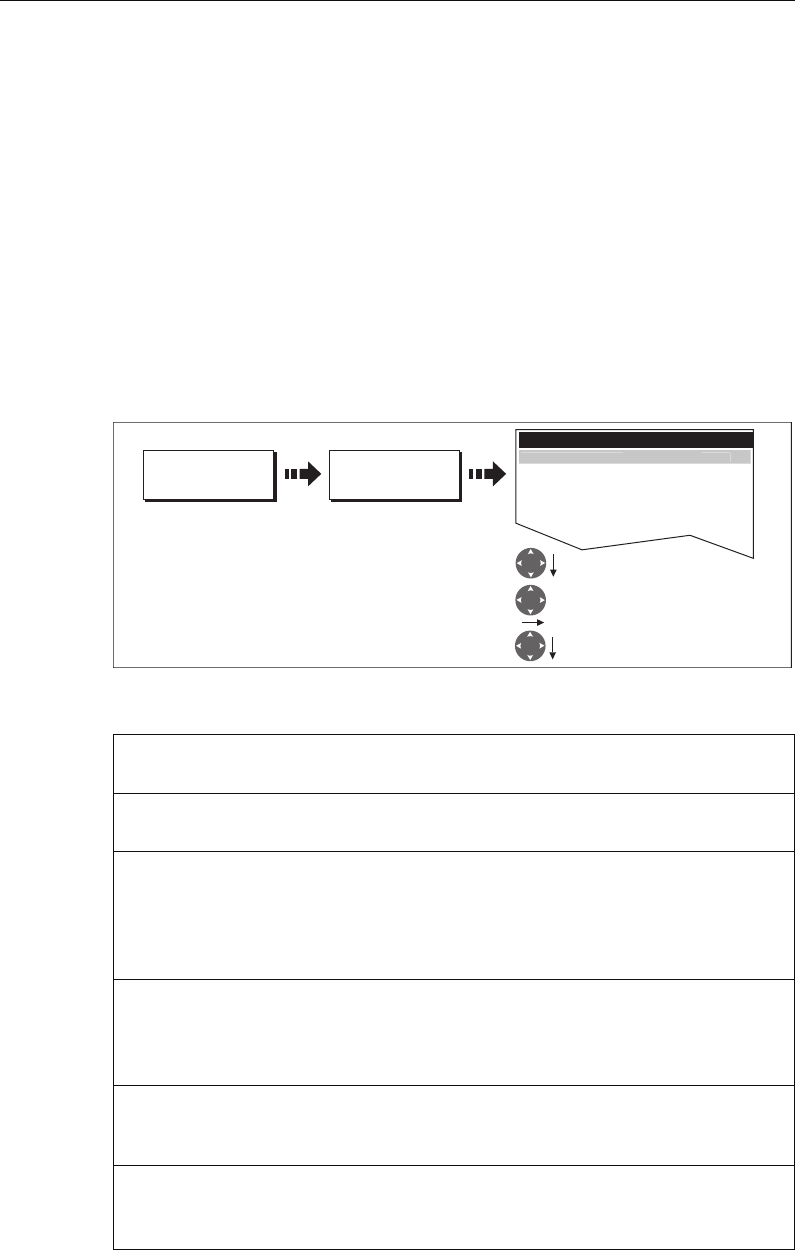
146 C-Series Display Reference Manual
True mode
With the display set in True mode, the vectors of your vessel and the target are shown
extended to their intersection point. The CPA is shown as a line that is placed on your
boat’s vector at the point of the CPA. The length and direction of the line indicates the
distance and bearing of the target at CPA. The text indicates CPA and TCPA. The text
next to the target symbol indicates its true course and speed.
Relative mode
With the display set in Relative mode, no vector extension of your boat is shown. The
CPA line emerges from your own boat, with the target vector extension being shown
as relative, not true. The text next to the target indicates its course and speed. Press
SHOW DETAILS to display the calculated relative course and speed.
Setting up MARPA
You can set up the following MARPA parameters:
Parameter Options
(Default in bold)
Vector Length
The time period specified for drawing length of vectors.
0.5min, 1 min, 3 min, 6min, 12min, 30
min, 60 min
Target History
Plots a target’s previous position at specified intervals.
The four most recent position points are displayed. If True
target vectors are selected, the four most recent vessel
position points are also displayed.
OFF, 0.5 min, 1 min, 3 min, 6 min
Own vessel safe zone
The safe zone is a ring, centred on your boat, within which
a target is considered dangerous if it will enter this zone
within the
time to safe zone
period.
0.1 nm, 0.2nm, 0.5nm, 1.0 nm, 2.0nm
Time to safe zone
If a target enters your safe zone within this time period, it
is considered dangerous.
3 mins, 6 mins, 12 mins, 24 mins
Safe zone ring
Controls whether the safe zone ring is displayed or hidden
on screen
Visible
Hidden
D6600-2
TARGET
TRACKING...
MARPA & AIS
OPTIONS...
Select required level
MARPA OPTIONS...
Enter highlighted parameter
Highlight required parameter
TARGET HISTORY Off
OWN VESSEL SAFE ZONE 0.5nm
TIME TO SAFE ZONE 3min
SAFE ZONE RING HIDDEN
V
ECT
O
R LEN
G
TH
6
min
81221_4.book Page 146 Tuesday, February 28, 2006 5:24 PM
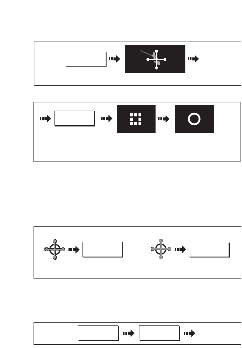
Chapter 6: Using the Radar 147
Acquiring a target to track
1. Select target to be acquired:
2. Acquire target:
Note:
If set to ON, the CPA graphic is displayed.
Cancelling targets
... from the screen
To cancel a target from the screen:
...from the MARPA list
To cancel a target from the MARPA list:
1. Display the MARPA List:
2. Cancel target/s:
D6829-2
TARGET
TRACKING...
Move cursor over target to be acquired
Target
D8806-1
ACQUIRE TARGET
'Target being acquired'
symbol displayed
If target present for several
scans, the radar will lock
onto it and change the
symbol to 'Safe'
D8434_1
CANCEL ALL
TARGETS
CANCEL TARGET
Move cursor
over target to
be cancelled
Cancelling an individual target Cancelling all targets
Move cursor
over target to
be cancelled
D8436_1
MARPA LIST...
TARGET
TRACKING...
81221_4.book Page 147 Tuesday, February 28, 2006 5:24 PM
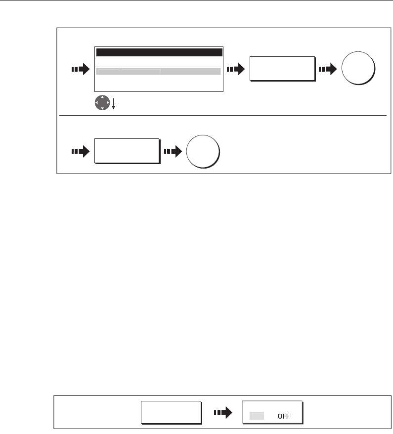
148 C-Series Display Reference Manual
Displaying vessel identity (AIS)
If you have an AIS receiver fitted to your system, you can use the AIS feature to:
• Display a target for any other AIS equipped vessels within a specified range of your
boat.
• Display voyage information being broadcasted by these targets i.e. their position,
course, speed and rate of turn.
• Display basic or detailed information for each target vessel including safety critical
target data.
• Set up a safe zone around your boat.
• View alarm and safety related messages.
This information is displayed in the form of an overlay or as a dialog box on your radar
screen. To overlay AIS on a radar window:
For more information on AIS, see
Chapter 11:Automatic Identification System (AIS)
.
6.11 Setting up your radar
The set up for your radar can be changed from the standard configuration to suit your
particular needs. Although you will probably only do this when you first use the radar,
you may decide to make subsequent adjustments once you become more familiar with
the system. Any settings that you change are retained and become the default settings
even when you power off.
To select the Radar Setup menus when a radar window is active:
D8435_1
CANCEL TARGET
To cancel an individual target:
MARPA LIST...
ID Bearing Range Course Speed CPA TCPA
2 1870T 4.0nm 1300T 1.5kt 4.0nm 8min
1 13
7
0
T
1.4nm 1
80
0
T 2.2kt 1.4nm 2mi
n
Highlight target to be cancelled
CANCEL ALL
TARGETS
To cancel all targets:
OK
OK
D9024_1
PRESENTATION AIS LAYER
O
N
81221_4.book Page 148 Tuesday, February 28, 2006 5:24 PM
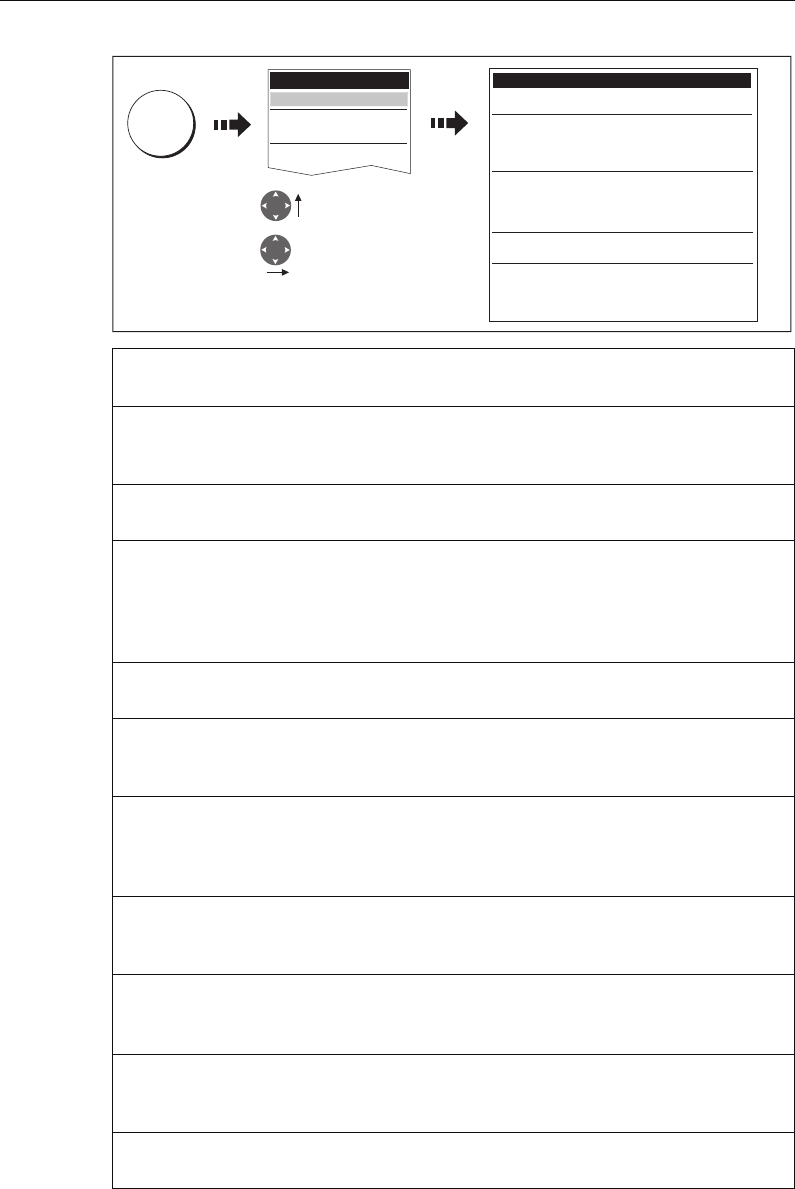
Chapter 6: Using the Radar 149
Function
Description
Options
(Default in bold)
Interference Rejection
When ON, any mutual radar interference between two radar equipped
vessels operating within range of each other, is automatically reduced.
NORMAL
HIGH
Target Expansion
When ON, targets are magnified to make them easier to see.
LOW
HIGH
Wakes Period
When ON, the target is displayed at the brightest level and its previous
positions are retained at successively fainter levels on the screen.
10 seconds
30 seconds
1 minute
5 minutes
10 minutes
Timed Transmit
Controls the radar’s timed transmission power-save mode.
OFF
ON
Transmit Period
When ON, the scanner performs the number of scans specified and then
shuts down for the number of minutes specified by the Standby Period.
10 scans
20 scans
30 scans
Standby Period
Indicates the number of minutes that the system shuts down - the scan-
ner does not rotate and the display is in standby mode.
3 minutes
5 minutes
10 minutes
15 minutes
Sea Clutter Curve...
Adjusts the acuteness of the sea clutter curve when the sea clutter
option is set to manual (see
page 122
).
1-8
Antenna Size
If an open array scanner is fitted, this specifies the size of the scanner.
Open array
48”
72”
Bearing alignment
Correct for display azimuth error.
Please refer to the C-Series installation guide.
Radar Advanced Setup
Please refer to the C-Series installation guide.
D8437_1
MENU
Highlight Radar
Setup menu
Enter Radar Setup
menu
Radar Setup Menu
Active Scanner 2kw Radome
Interference Reject NORMAL
Target Expansion LOW
Wakes Period 1min
Timed Transmit OFF
Transmit Period 10 SCANS
Standby Period 3 MINS
Sea Clutter Curve...
Antenna Size Radome
Bearing Alignment
Radar Advanced Setup...
Setup
Radar Setup...
GPS Status...
Compass Setup...
System Setup...
81221_4.book Page 149 Tuesday, February 28, 2006 5:24 PM
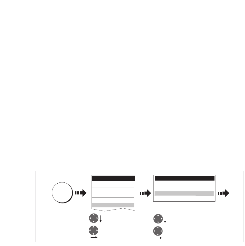
150 C-Series Display Reference Manual
6.12 Warnings of potential dangers
If switched on, the following alarms will be triggered when you are in the radar
application:
• System alarms - anchor, timer, alarm clock and temperature.
• Navigation alarms - arrival and off track.
• Radar alarms - guard zones.
•Fishfinder alarms.
• AIS alarms.
• Depth alarms.
• Data alarms.
• External SeaTalk alarms.
When an alarm is triggered, a buzzer sounds and a pop-up window describing the
alarm and how to clear it is displayed.
To switch these alarms on/off and set the limits:
Note:
For more details of alarms, see page 27 and page 187.
D8438_1
MENU
Highlight Alarm
Setup menu
Enter Alarm Setup
menu
Highlight appropriate
sub-menu
Enter sub-menu
Alarm Setup Menu
System Alarms Setup...
Navigation Alarms Setup...
Fishfinder Alarms Setup...
Ra
d
ar A
l
arms Setup..
.
Setup
Radar Setup...
GPS Status...
Compass Setup...
System Setup...
Alarm Setup...
81221_4.book Page 150 Tuesday, February 28, 2006 5:24 PM
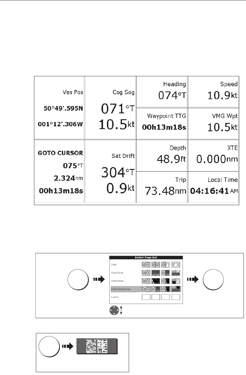
Chapter 7: Using the data application 151
Chapter 7: Using the data application
7.1 Introduction
The data application enables you to view numeric data generated by the system or by
instruments available on NMEA or SeaTalk.
7.2 Selecting a data application
To select a data application:
1. Select a page set that includes a data application:
2. Select a page which includes a data window:
D9010_1
D8465_1
PAGE OK
Press and
hold
Highlight suitable page set with
Digital Data application
D8464_1
PAGE
Press Select page including
Digital Data application
81221_4.book Page 151 Tuesday, February 28, 2006 5:24 PM
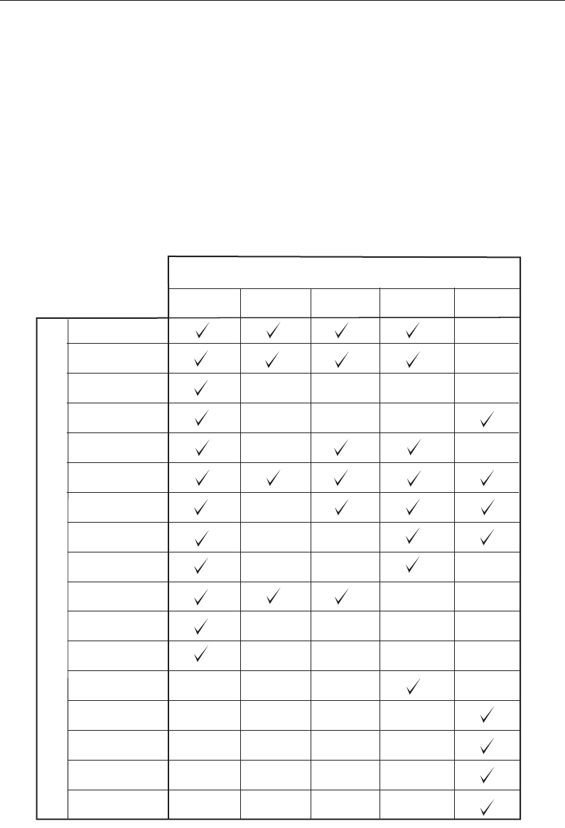
152 C-Series Display Reference Manual
7.3 Selecting the data for display
You can either select a panel of pre-configured data or customize the application to
display the data of your choice.
Note:
Panel selection is a local setting and will therefore only affect the individual dis-
play on which you are working.
Pre-configured data panels
The pre-configured data panels include data associated with Navigation, Waypoint,
Route, Fishing or Sailing:
Vessel position
Active waypoint
TTG
VMG - Waypoint
Depth
Cog Sog
Heading
Speed
Set/Drift
XTE
Trip
Local time
Sea temperature
Ground wind
App wind
True wind
VMG wind
Panel Type
Navigation Waypoint Route Fishing Sailing
D8950_1
Data content
81221_4.book Page 152 Tuesday, February 28, 2006 5:24 PM
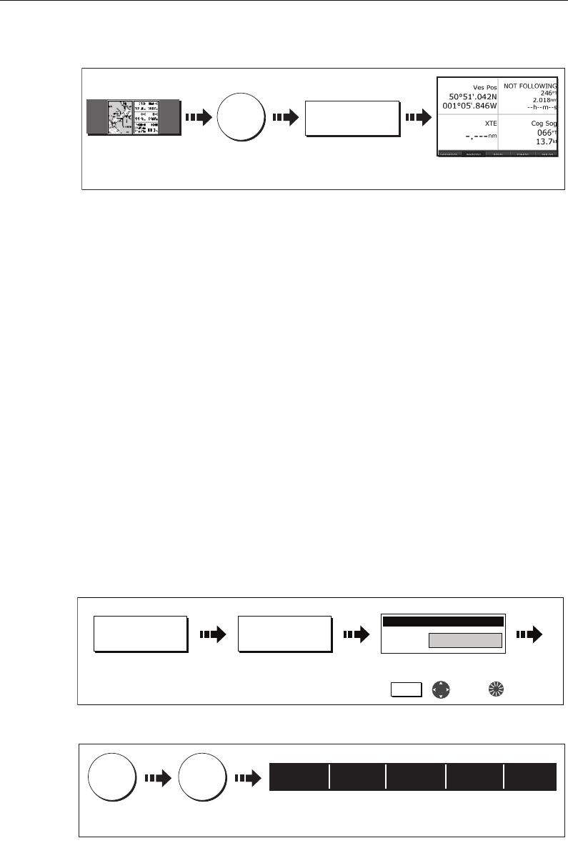
Chapter 7: Using the data application 153
To select a pre-configured data panel:
Customize the panels
You can customize each panel by changing:
• The panel name.
• The size and number of data cells
• The data contained in each cell. This data can include any transducer or internally
calculated navigation data that is available on NMEA or SeaTalk. Additional data
includes a compass rose, a distance log and four resettable trip counters.
• How the data is displayed. You can control whether the data is displayed in numer-
ical, digits, gauge or graphical format as appropriate to each data item.
Note:
You can also configure the data panels in this way in the Engine Monitoring and
CDI applications.
Renaming a panel
You can customize the names of the panels as required e.g. the SAILING panel could be
renamed RACING:
1. Select and rename the appropriate panel:
2. Save the changes:
D8466_1
ACTIVE
Move control
to Digital Data
window
Select required
panel type Selected panel type
displayed
e.g.
Select page including
Digital Data application
WAYPOINT
D8732_1
RENAME PANEL...SAILING
Press and hold soft key
of panel for renaming
e.g. e.g.
,
To rename the panel use:
and/or
Rename Instrument panel
Soft key
Panel name Raci
D8733_1
OK OK
e.g.
To return to
panel soft keys
Soft key changes to reflect renamed panel
NAVIGATION WAYPOINT ROUTE FISHING Racing
81221_4.book Page 153 Tuesday, February 28, 2006 5:24 PM
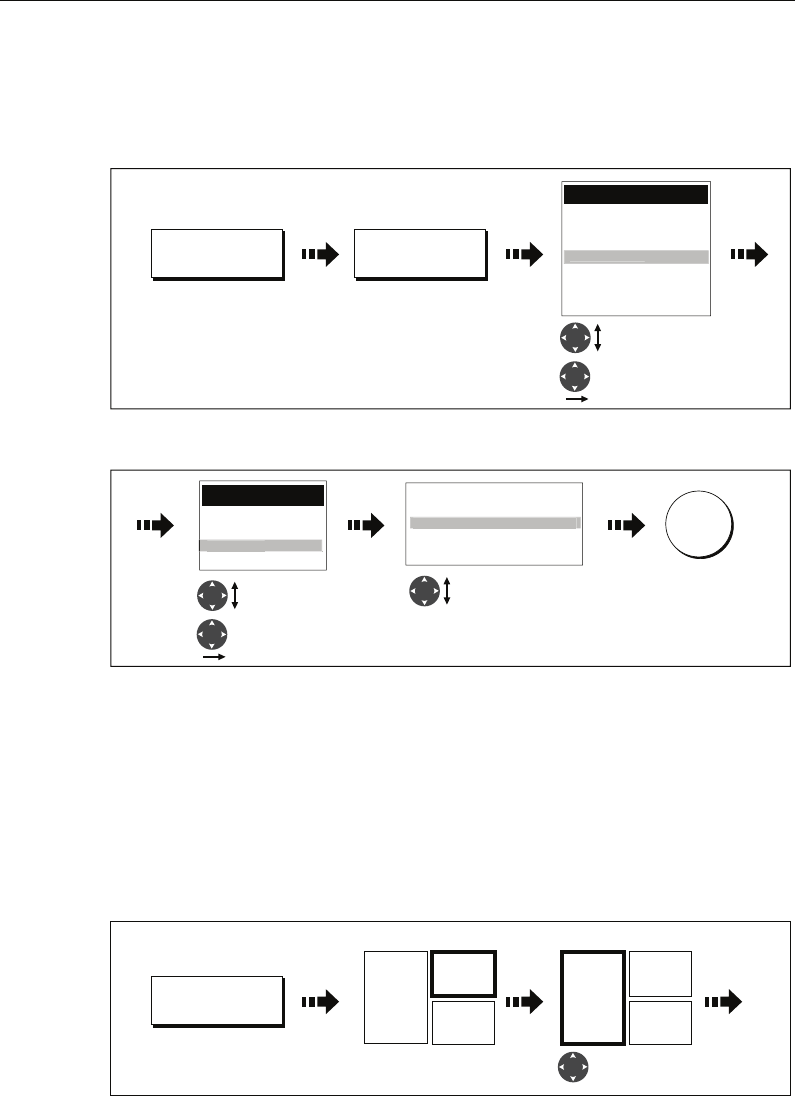
154 C-Series Display Reference Manual
Selecting cell data
To select the data that is to appear in each cell:
1. Select the data group for the relevant panel e.g.
2. Select the data to be inserted in the highlighted panel:
Changing the size of the cells
You can change the size of the cells to meet your own particular requirements by using
the MERGE CELLS or SPLIT CELL function.
Splitting a cell
Use the SPLIT CELL function to create two smaller data cells:
1. Select the relevant cell within the required panel:
The direction in which the selected cell can be split is indicated on the soft key.
2. Split the highlighted cell:
D9106_1
Data Groups
Vessel
Navigation
Depth
Wind
Time and Date
Engine
Envir
o
nmen
t
Highlight data
group
Select data group
SELECT DATA...
SAILING
Press and hold
relevant soft key
e.g.
D8729_1
Data
Pressure
Air Temp
Set Drift
S
ea Tem
p
p
Numeric
Graph - 1 Second Interval
Graph - 1 Minute Interval
Graph - 5 Minute Interval
G
ra
p
h - 10 Second Interval
p
Highlight
required data
Select data
Select format
(if applicable)
OK
D9107_1
NAVIGATION
Press and hold
relevant soft key
e.g.
Active cell highlighted Move highlight
to relevant cell
Heading
2960T
Speed
20.0kt
Trip
13.85nm
e.g.
Heading
2960T
Speed
20.0kt
Trip
13.85nm
e.g.
81221_4.book Page 154 Tuesday, February 28, 2006 5:24 PM
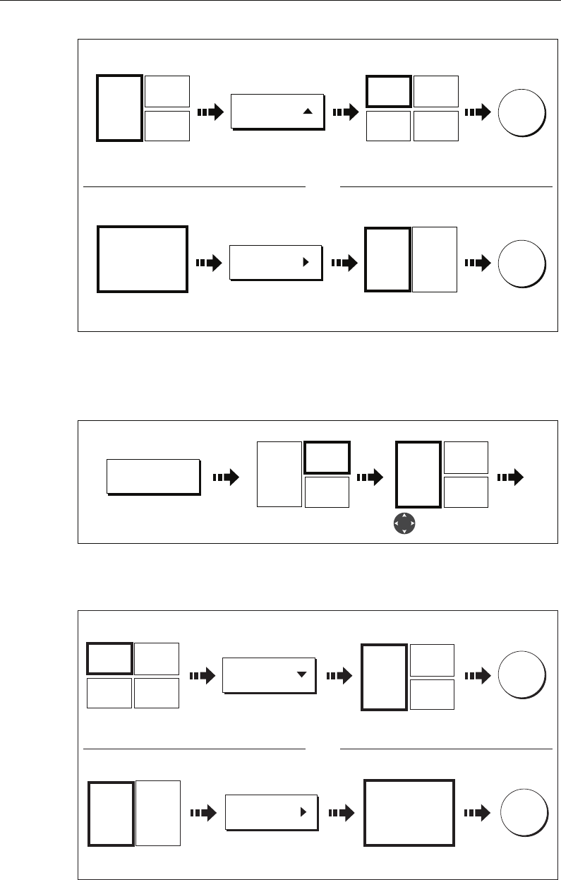
Chapter 7: Using the data application 155
=
Merging a cell
Use the MERGE CELLS function to make a cell larger and therefore easier to see:
1. Select the relevant cell within the required panel:
The direction in which the selected cell can be merged is indicated on the soft key.
2. Merge the highlighted cell:
D8730_1
OK
SPLIT CELL
Heading
2960T
Speed
20.0kt
Trip
13.85nm
Heading
2960T
Speed
20.0kt
Trip
13.85nm
Depth
48.5ft
Cell for splitting
selected
e.g. e.g.
Cell splits horizontallySoft key indicates
direction of split
OK
SPLIT CELL
Heading
2960T
Heading
2960T
Speed
20.0kt
Cell for splitting
selected
e.g. e.g.
Cell splits verticallySoft key indicates
direction of split
Split horizontally
Split vertically
OR
D9107_1
NAVIGATION
Press and hold
relevant soft key
e.g.
Active cell highlighted Move highlight
to relevant cell
Heading
2960T
Speed
20.0kt
Trip
13.85nm
e.g.
Heading
2960T
Speed
20.0kt
Trip
13.85nm
e.g.
D8731_1
OK
MERGE CELLS
Heading
2960T
Speed
20.0kt
Trip
13.85nm
Heading
2960T
Speed
20.0kt
Trip
13.85nm
Depth
48.5ft
Cell for merging
selected
e.g. e.g.
Cell merges
horizontally
Soft key indicates
direction of merge
OK
MERGE CELLS
Heading
2960T
Heading
2960T
Speed
20.0kt
Cell for merging
selected
e.g. e.g.
Cell merge vertically
Soft key indicates
direction of merge
Merge horizontally
Merge vertically OR
81221_4.book Page 155 Tuesday, February 28, 2006 5:24 PM

156 C-Series Display Reference Manual
81221_4.book Page 156 Tuesday, February 28, 2006 5:24 PM
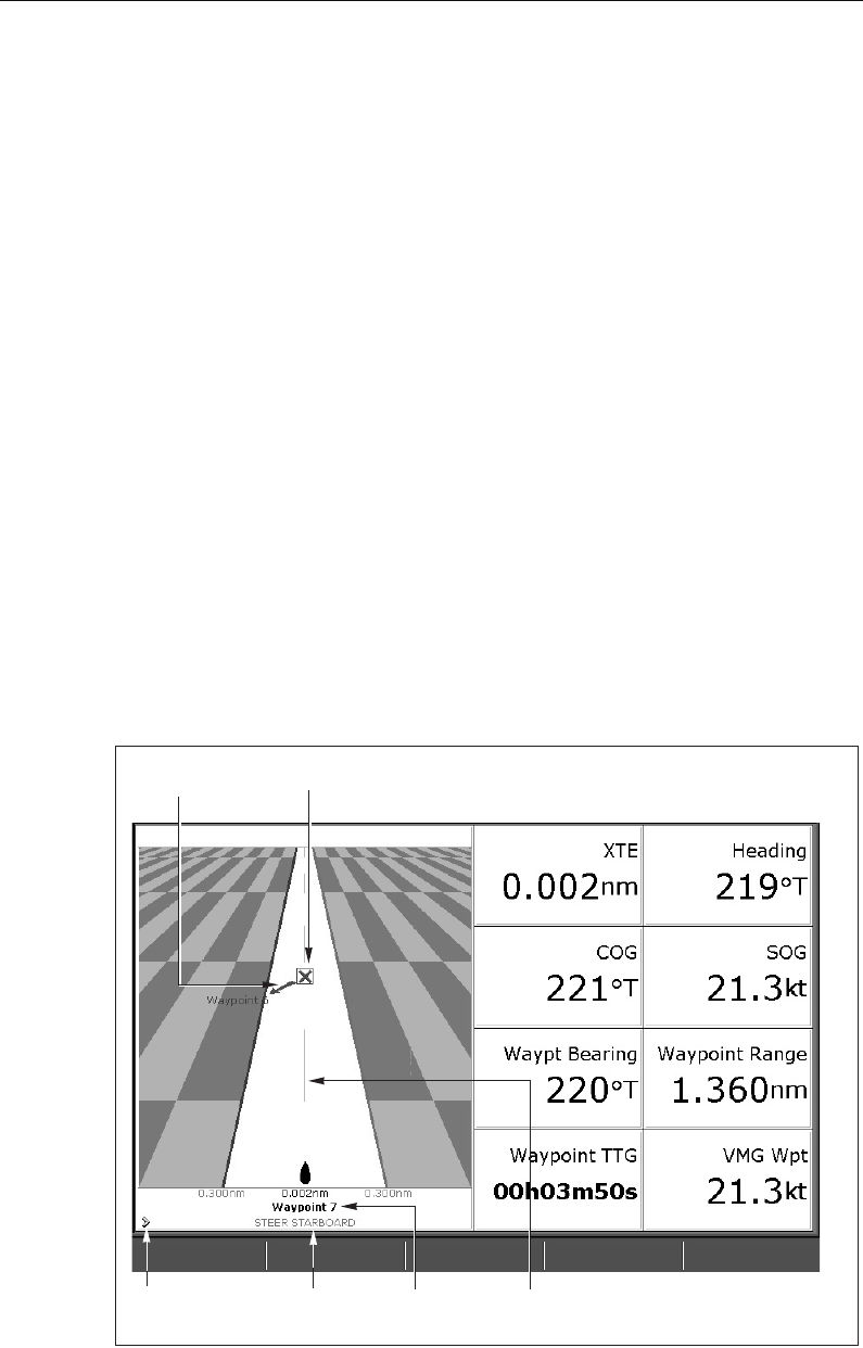
Chapter 8: Using the Course Deviation Indicator 157
Chapter 8: Using the Course Deviation
Indicator
8.1 Introduction
With your display receiving accurate heading and position information, you can use
the Course Deviation Indicator (CDI) to monitor your course and accurately steer to a
target waypoint.
The CDI application is pre-configured to display the CDI graphic. You can customize the
panel to display any available data.
8.2 The CDI screen
The CDI gives a graphical representation of yours boat’s course in a ‘rolling road’
format.
The ‘rolling road’ represents a width of sea equal to the Cross Track Error (XTE) limits
that you have specified in the Setup menu. As you travel towards the target waypoint,
the checkered pattern and the waypoint will move down the screen at a rate
proportional to your boat’s speed.
Navigation data is displayed alongside or below the rolling road.
D6778-4
On course
line
Target way-
point name
Target waypoint
Direction to steer
to maintain course
Direction
to steer
Indicates direction
of next waypoint
81221_4.book Page 157 Tuesday, February 28, 2006 5:24 PM
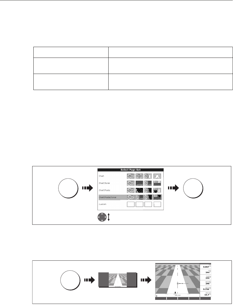
158 C-Series Display Reference Manual
Steering instructions
The steering instructions below the rolling road tell you what correction is needed to
maintain your course and arrive at the target waypoint.
Indication arrows are placed either side of the steering instruction, pointing towards
the centre line. The greater the error the more arrows appear. You should correct your
course by steering in the direction indicated by the arrows.
8.3 Selecting the CDI application
To select the CDI application:
1. Select a page set which includes a CDI application:
Note: If the CDI application is placed in multiple windows, the same data is dis-
played in each.
2. Select a page which includes a CDI window:
Once the CDI application is displayed, no use is made of the soft keys. You will
therefore need to open a radar, chart or fishfinder window in order to access any
functions activated via the soft keys.
8.4 Modifying the CDI application
If required, you can modify the information displayed in the CDI application window to
meet your own particular requirements. For details, please refer to
page 180
.
Instruction Cause
STEER STARBOARD XTE error to port is more than a 1/4 of the maximum XTE error
limit in the Setup menu
STEER PORT XTE error to starboard is more than a 1/4 of the maximum XTE
error limit in the Setup menu
D8462_1
PAGE OK
Press and
hold
Highlight suitable page set with
CDI application
D8463_1
PAGE
Select page including
CDI window
STEER TO STARBOARD
81221_4.book Page 158 Tuesday, February 28, 2006 5:24 PM
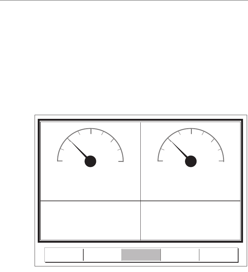
Chapter 9: Using the Engine Monitor 159
Chapter 9: Using the Engine Monitor
9.1 Introduction
The engine monitor application enables you to view information in the form of gauges
and digital data, from up to three compatible engines. To provide a fast update rate,
the engine data is transferred from the engine’s serial interface to your C-Series display
via NMEA2000/SeaTalk2.
Note: For details of compatible engines and related software updates, please re-
fer to the Raymarine website on www.raymarine.com.
If the pre-configured content of these panels and/or the layout of the individual data
boxes is not suitable, you can configure the system to display the data and layout of
your choice - see
page 153
.
9.2 Displaying and setting up the engine monitor
Before using the engine monitor application you should set up your system as follows:
1. Customize a page set to include an engine monitor application window. For details
of how to select a particular window and application, please refer to
page 177
.
2. Set the number of engines and the maximum tachometer range to reflect your par-
ticular vessel:
00
25 25
50 50
75 75
100 100
%%
Fuel 1 Fuel 2
Fuel Rate
11.61
gals/h
Fuel Rate
13.95
gals/h
D7516_3
ENGINE ENGINE &
FUEL
ENGINE &
RESOURCES TWIN ENGINE
FUEL
R
ESOURCES
81221_4.book Page 159 Tuesday, February 28, 2006 5:24 PM
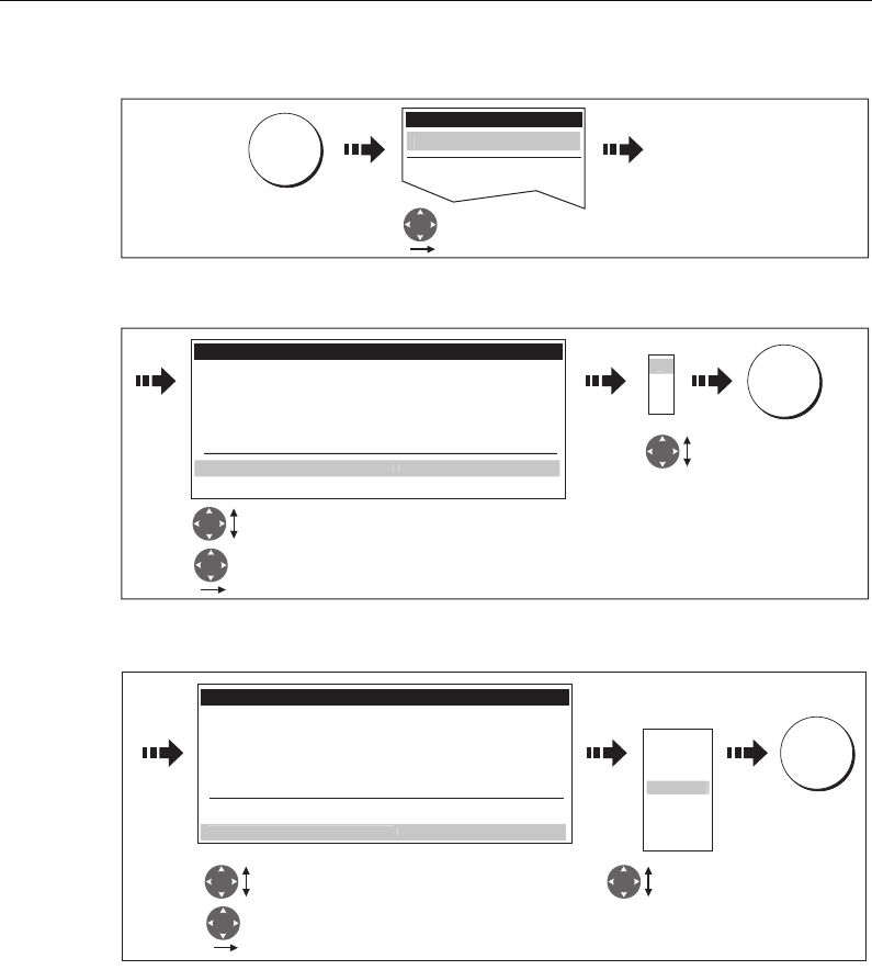
160 C-Series Display Reference Manual
i. With an engine monitor window active, select the Panel Setup Menu:
ii. Set the number of engines:
iii. Set the maximum tachometer range:
Note: The engine temperature unit (0F or 0C) and the fuel unit (litres, imperial
gallons or US gallons) is defined in the System Setup Menu (Units Setup) and is
detailed on page 185.
D8707_1
MENU
Setup
GPS Setup...
Select Panel Setup
Menu
Pane
l
Setu
p
Menu..
.
D8933_1
Panel Setup Menu
Configure: ENGINE...
Configure: ENGINE & FUEL...
Configure: FUEL RESOURCES...
Configure: ENGINE & RESOURCES...
Configure: TWIN ENGINE...
Maximum tachometer range AUTO
Select Number of Engines
Highlight Number of Engines
Set number
of engines
for your boat
Number o
f
Engines
1
2
3
1
OK
D8708_1
Select maximum
tachometer range
Highlight maximum
tachometer range
Set maximum
tachometer
range for your
boat
Auto
3000rpm
4
000
r
pm
p
6000rpm
7000rpm
8000rpm
5
000
r
pm
Panel Setup Menu
Configure: ENGINE...
Configure: ENGINE & FUEL...
Configure: FUEL RESOURCES...
Configure: ENGINE & RESOURCES...
Configure: TWIN ENGINE...
Number of Engines 1
Maximum tachometer ran
g
e AUTO
OK
81221_4.book Page 160 Tuesday, February 28, 2006 5:24 PM
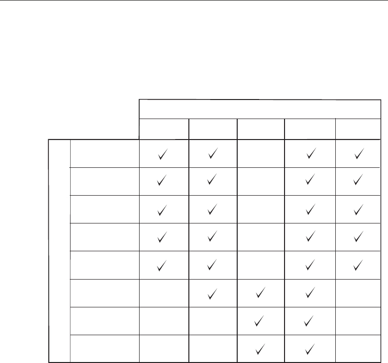
Chapter 9: Using the Engine Monitor 161
9.3 The engine monitor display
Engine data is displayed in a series of pre-configured panels. Each panel contains a
particular set or data. You can choose the panel that suits your requirements via the
soft keys:
9.4 Configuring the engine panels.
You can configure each panel by changing the size and number of data cells and the
data contained in each cell. You can also rename each panel. For further detail, please
refer to
page 153
.
Note: Configuring engine panels is a local setting and will therefore only affect
the individual display on which you are working.
9.5 What should I do when an alarm is triggered?
Your engine monitor application will trigger an alarm (via NMEA/SeaTalk2) and display
an engine alarm warning message when a problem is detected. When this occurs, you
should check your engine monitoring system and if necessary refer to the
documentation supplied with your engine system. Press ACKNOWLEDGE to silence
the alarm.
Note: When engine monitoring is active, all other system alarms continue to trig-
ger.
Panel Type
D9105_1
Data content
Tacho &
engine hours
Oil pressure
Engine coolant
temperature
Boost
pressure
Alternator
Fuel level
(tanks 1 & 2)
Fuel rate
Total fuel
Engine Engine
& fuel
Fuel
resources
Engine &
resources
Twin
engines
81221_4.book Page 161 Tuesday, February 28, 2006 5:24 PM

162 C-Series Display Reference Manual
81221_4.book Page 162 Tuesday, February 28, 2006 5:24 PM

Chapter 10: Navtex 163
Chapter 10: Navtex
10.1 Overview
The display can be used to view marine safety information including weather forecasts
and marine warnings received from a Navtex receiver. You can select the type of
warning message that will trigger this alert on your display. Once you have read the
received message you can either erase or save it. Your system can store up to 100
messages. Once capacity is reached the oldest messages are automatically deleted to
allow for new incoming messages.
Major areas of NAVTEX coverage include the Mediterranean Sea, The North Sea,
coastal areas around Japan and areas around the North American continent.
10.2 Setting up Navtex weather
Before you are able to view Navtex messages you will need to:
1. Specify for the communicating NMEA port, the baud rate (4,800 or 9,600) applica-
ble to your Navtex receiver (see
page 186
).
2. Enable the category of Navtex messages that you wish to receive alerts for (see
page 164
).
10.3 Incoming message alerts
Once correctly connected to the Navtex unit, your system will display an alert
containing the message details for any incoming messages it receives from your
chosen categories e.g:
Proceed as follows:
• To remove the alert from the screen, press ERASE, or
• To add the message to the stored list of messages and then remove the alert from
the screen, press SAVE MESSAGE.
D8870_1
ERASE MESSAGE SAVE MESSAGE
81221_4.book Page 163 Tuesday, February 28, 2006 5:24 PM
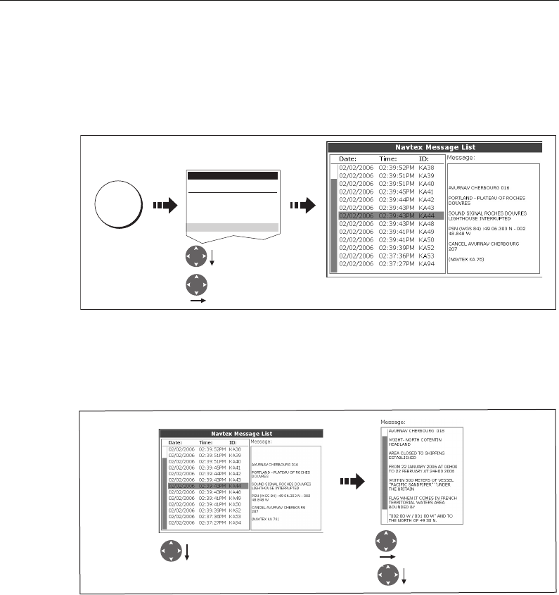
164 C-Series Display Reference Manual
10.4 Viewing messages
Displaying the Navtex Message List
To view messages stored in your system:
You now have the option to SORT LIST (by date, station or category), erase a message
or set up the message alerts
Displaying and scrolling through a message
10.5 Managing Navtex messages
You can manage your messages by:
• Selecting the message categories for which the C-Series system will provide alerts.
• Erasing messages that you do not need.
• Sorting the message list.
Selecting message alert categories
On initial power up, the system provides alerts for all message categories listed in the
Navtex Alert Menu. If required you can switch off any categories that you do not need
except Navigation Warnings (Category A), Meteorological Warnings (Category B) and
Search and Rescue information (Category D).
D8871_1
Setup
Radar Setup...
GPS Setup...
Compass Setup...
AIS Setup...
Navtex Messages
Highlight Navtex
messages
Select Navtex
messages
MENU
D8872_1
Highlight required item in list.
Associated message displayed
in message box
Move control to
message box
Scroll message
(if applicable)
81221_4.book Page 164 Tuesday, February 28, 2006 5:24 PM
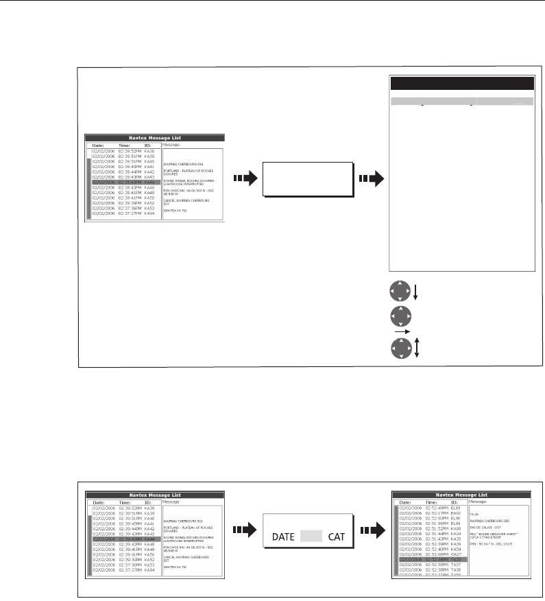
Chapter 10: Navtex 165
To select the message alert categories:
Sorting the message list
By default the message list sorts by the date and time the message was received
(DATE) with the most recent message at the top. If required, you can sort the list by
station identifier (STN) or by message category (CAT).
D8876_1
Highlight category
Select category
Toggle to required status
SETUP ALERTS
Navtex Alert Menu
B - Meteorological warnings ON
C - Ice reports ON
D - Search and rescue information ON
E - Meteorological forecasts OFF
F - ilot service messages OFF
G - Decca messages OFF
H - Loran messages ON
I - Omega messages OFF
J - Satnav messages ON
K - Other electronic navaid messages ON
L - Additional navigational messages ON
V - Notice to fishermane (US only) ON
W - Environmental (US only) OFF
X - Special services ON
Y - Special services ON
Z - No message on hand (QRU) ON
A - Navi
g
ationa
l
warnin
g
s
ON
D8875_1
Toggle to required sort
option e.g. station
List sorts accordinglyList sorted by DATE (default)
SORT LIST
S
TN
e.g.
81221_4.book Page 165 Tuesday, February 28, 2006 5:24 PM

166 C-Series Display Reference Manual
81221_4.book Page 166 Tuesday, February 28, 2006 5:24 PM

Chapter 11: Automatic Identification System (AIS) 167
Chapter 11: Automatic Identification System
(AIS)
11.1Introduction
This chapter details the AIS system and how it can be used as a safety aid. Once set up
you can overlay the AIS on chart or radar windows and use it to:
• Display a target (with heading/speed vectors and rate of turn) for any other AIS
equipped vessels.
• Display basic or detailed information for each target vessel including safety critical
target data.
• Set up a safe zone around your boat.
• View alarm and safety related messages.
11.2What is AIS?
AIS uses digital radio signals to broadcast ‘real-time’ information between vessels and
shore based stations via dedicated VHF frequencies. This information is used to identify
and track vessels in the surrounding area and to provide fast, automatic and accurate
collision avoidance data. AIS will augment your radar application, as it can operate in
radar blind spots and can detect smaller AIS fitted vessels.
WARNING:
Smaller vessels do not have to be fitted with AIS and whilst it is mandatory
for larger commercial vessels to carry AIS, its use is not. You should not
therefore assume that your AIS will display ALL vessels in your area. Due
prudence and judgement should be exercised.
AIS should be used to complement not substitute radar.
Classes of AIS data
AIS data is defined as Class A or Class B. The sending and receiving of Class A data is
compulsory for larger vessels. You will therefore be able to view all larger vessels on
your AIS display. Class B data is applicable to smaller vessels and is not compulsory.
You should not therefore assume that your AIS is displaying all smaller vessels in your
area.
Note: Not all AIS receivers will decode all information and not all of the Class A vessels
input all of the required AIS data. For example, some inexpensive AIS Class B receivers
do not decode and output the ship’s name, IMO number and vessel draft/beam/length,
destination etc.
81221_4.book Page 167 Tuesday, February 28, 2006 5:24 PM
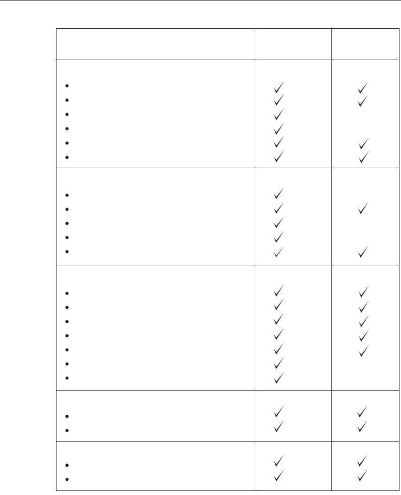
168 C-Series Display Reference Manual
Note: To change the specified AIS targets and range see page 173.
D8966_1
Static Data
Ship's name
Type
Call sign
IMO number
Length and beam
Antenna loctation
Draft
Cargo information
Destination
ETA
Other relevant information
Time
Ship's position
COG
SOG
Gyro heading
Rate of turn
Navigational status
Dynamic Data
Voyage Related Data
Data details Class A
(Sends and receives)
Class B
(receives only)
Ship's speed
Ship's status
Dynamic Reports
Alarm
Safety
Messages
81221_4.book Page 168 Tuesday, February 28, 2006 5:24 PM
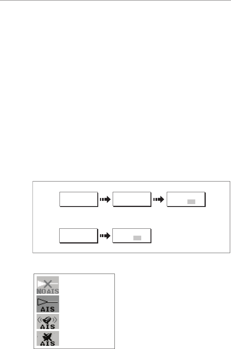
Chapter 11: Automatic Identification System (AIS) 169
11.3 What do I need to run AIS?
In order to run AIS, you will need:
• A receive only unit or a full transponder.
Note:
A receiver will allow you to receive data about other vessels in your area but will not
allow other vessels to ‘see’ you. A full transponder transmits and receives AIS data and
therefore allows you to receive data about other vessels and for other AIS equipped vessels
to see and receive information about your vessel. This could include position, course, speed
and rate of turn data.
• A VHF antenna - this is usually supplied with the AIS system.
• A GPS - to provide position data.
• A Compass - although not essential, will improve speed calculations.
When the AIS unit is connected to the C-Series display, the status of the unit is
indicated by an AIS icon in the transducer data box.
You will now need to specify the 38,400 baud for the NMEA port that communicates
with the AIS transceiver or receiver (see
page 186
).
11.4Selecting the AIS function
AIS is a selectable layer of the chart or radar application. To switch on AIS:
AIS status
The status of the AIS is displayed in the data bar
on your display.
If your own boat’s position is lost the display
will disable the AIS functionality and will
display the AIS indicator in parenthesis.
Once your own boat’s position returns and the
AIS display is switched on, the display will re-
enable the AIS function.
PRESENTATION...
D8521_1
Toggle as required
On chart windows:
On radar windows:
CHART LAYERS...
PRESENTATION...
Toggle as required
AIS LAYER
ON OFF
AIS LAYER
ON OFF
D9014_1
AIS unit not available
i.e. not connected or off.
AIS unit switched on and
operating.
AIS unit switched on and
operating but dangerous &
lost target alarm disabled.
AIS unit on with active
alarm.
81221_4.book Page 169 Tuesday, February 28, 2006 5:24 PM
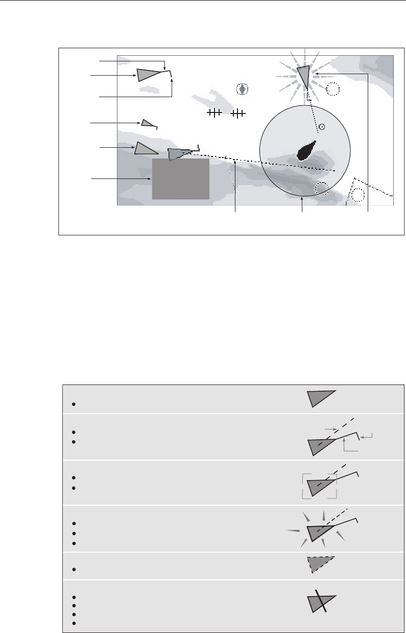
170 C-Series Display Reference Manual
11.5How is AIS data displayed?
The AIS system displays other AIS equipped vessels in the surrounding area as
triangular targets overlaid on a chart or radar window. Up to 100 targets are displayed.
As the vessel’s status changes, the symbol for the target will change accordingly.
Vectors can be displayed for each target. These vectors indicate the direction of travel
and rate of turn of the vessel and the distance it will travel over a specified period of
time (COG/SOG vector). Targets displayed with their vectors are referred to as ‘active
targets’ and are scaled according to the size of the vessel. The larger the vessel the
larger the target. You can either display all targets or just dangerous targets (
page 176
).
AIS Target symbols
D9056_1
097°T
11.6kt
1.237nm
00h04m33s
Safety
critical data
Heading
Large
vessel
Direction
of turn
Small
vessel
Sleeping
target
Dangerous
target (flashes)
Safe zone (defined by
distance or time)
COG/SOG
vector
Uncertain target
Calculated CPA/TCPA value uncertain.
Sleeping target
Target not activated, dangerous or lost.
Activated target
Target activated i.e. AIS vector displayed.
Vector line (optional) shows predicted distance travelled within
given time.
Dangerous target
Targets within specified distance (CPA) or time (TCPA).
Dangerous target alarm sounds if en-abled.
Target flashes.
Lost target
When signal of dangerous target not received for 20 seconds.
Target in latest predicted position.
Alarms sounds if enabled.
Target flashes.
Selected target
Target selected with cursor.
Can activate the target and view detailed data.
COG/SOG
vector
Heading
Direction
of turn
AIS
D8523-1
81221_4.book Page 170 Tuesday, February 28, 2006 5:24 PM

Chapter 11: Automatic Identification System (AIS) 171
Viewing target information
You can display information relating to individual AIS targets. When a target is
highlighted with the cursor. The soft keys change to allow you to select the following
options:
• AIS vectors.
• AIS safety critical data.
•AIS List.
•Full AIS data.
Displaying AIS vectors
A target is defined as active when it has the following data displayed graphically:
• A COG/SOG vector indicating the predicted distance that a target will travel within
a given period of time.
• A heading and direction of turn indicator.
To switch the AIS VECTOR option ON/OFF:
When a target is activated, its symbol is scaled according to the size of the vessel.
Note: The same target vector and safe zone settings apply to both Radar MARPA and
AIS targets.
Displaying safety critical AIS data
Safety critical target data i.e. COG, SOG, CPA and TCPA can be displayed in the tag
alongside each target. You can switch this data ON, OFF or display it automatically
(AUTO) when the cursor is over the target.
To switch the AIS DATA option to AUTO/ON/OFF:
D9051_1
Move cursor over
relevant target
AIS AIS
AIS VECTOR
O
N
D9052_1
Move cursor over
relevant target Safety critical data
displayed
AIS DATA
AU
T
O
1870T
10.9kt
7.719nm
00h57m27s
AIS
81221_4.book Page 171 Tuesday, February 28, 2006 5:24 PM
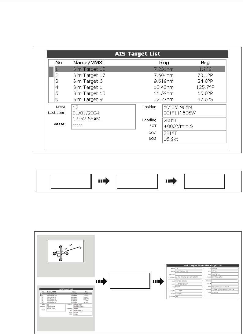
172 C-Series Display Reference Manual
AIS List
You can also view a list of AIS targets. The list provides collision avoidance data for the
highlighted target:
To display the AIS List:
Viewing full AIS data
To display detailed AIS data for an individual target e.g. static and dynamic and voyage
related data:
D9092_1
D9091_1
AIS OPTIONS... TARGET
TRACKING... AIS LIST
D8693_1
Move cursor over
required target
Select required target
on AIS list
VIEW FULL AIS
DATA...
Or
81221_4.book Page 172 Tuesday, February 28, 2006 5:24 PM
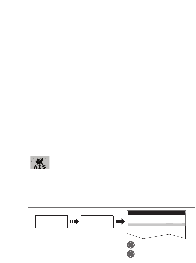
Chapter 11: Automatic Identification System (AIS) 173
11.6Using AIS for collision avoidance
You can use your AIS for collision avoidance by using the safe zone and safety message
functions.
Safe zones
What is a safe zone?
A safe zone is a ring centred on your boat within which a target is considered
dangerous. It is displayed on radar or chart windows as a red ring.
This AIS safe zone uses the same criteria as MARPA and will deem a target dangerous
if it comes within a specified distance of your vessel (closest point of approach or CPA)
within a specified time (time to closest point of approach or TCPA). The CPA and TCPA
are calculated using COG/SOG and position from the AIS target.
When your system recognizes a dangerous AIS target:
• The target symbol changes to red and flashes.
• An alarm pop-up is displayed.
• An alarm sounds.
Disabling the dangerous target alarm
If required, the dangerous target alarm can be disabled. Once disabled
any dangerous targets that are detected, will turn red and flash but the
alarm will not sound and the pop-up will not be displayed. The AIS
status icon reflects that the alarm is disabled.
Setting up an AIS safe zone
To set up a safe zone around your vessel and specify the time to safe zone:
Note: If required you can also hide the safe zone ring via this menu.
Important
When the AIS receiver is connected and functioning, the system will check for
dangerous targets within the safe zone and if enabled issue an alarm whenever
necessary. Dangerous target alarm operates irrespective of the ON or OFF status of the
AIS target display (see
page 176
) or the VISIBLE/HIDDEN status of the safe zone ring
D9082_1
D8688_1
TARGET
TRACKING...
MARPA & AIS
OPTIONS...
Highlight and select TIME TO SAFE
ZONE. Select required duration.
MARPA & AIS OPTIONS...
Highlight and select OWN VESSEL
SAFE ZONE. Select required distance.
VECTOR LENGTH 6min
TARGET HISTORY Off
TIME TO SAFE ZONE 3min
SAFE ZONE RING HIDDEN
O
WN VESSEL SAFE ZONE 0.5n
m
81221_4.book Page 173 Tuesday, February 28, 2006 5:24 PM

174 C-Series Display Reference Manual
MARPA and AIS options
Safety messages
When the status of the AIS Safety Messages function is set to ON in the AIS Layer Setup
Menu (see
page 176
), any incoming safety messages from surrounding vessels, shore
stations and mobile stations, are displayed in a pop-up box. If known, the message will
include the sending vessel’s position in lat/lon.
You now have the option to:
• Remove the message (ACKNOWLEDGE)
• Place a waypoint on your chart/radar to mark the sending vessel’s position.
• Select to GOTO the sending vessel’s position.
Note: When the simulator is operating you will not be able to receive any safety mes-
sages.
11.7AIS Alarms
In addition to the dangerous target alarm previously described, the system generates
an alarm when a dangerous target becomes a lost target i.e. its signal has not been
received for 20 seconds.
Your AIS receiver generates local alarms which are displayed and sounded on your C-
Series display whenever an alarm condition exists on the unit.
Parameter Options
(Default in bold)
Vector Length
The time period specified for drawing length of vectors.
0.5min, 1 min, 3 min, 6min, 12min, 30
min, 60 min
Target History
Plots a MARPA target’s previous position at specified
intervals. The four most recent position points are dis-
played. If True target vectors are selected, the four most
recent vessel position points are also displayed.
OFF, 0.5 min, 1 min, 3 min, 6 min
Own vessel safe zone
The safe zone is a ring, centred on your boat, within which
a target is considered dangerous if it comes within a spec-
ified distance (CPA).
0.1 nm, 0.2nm, 0.5nm, 1.0 nm, 2.0nm
Time to safe zone
If a target enters your safe zone within this time period, it
is considered dangerous.
3 mins, 6 mins, 12 mins, 24 mins
Safe zone ring
Controls whether the safe zone ring is displayed or hidden
on screen
Visible
Hidden
81221_4.book Page 174 Tuesday, February 28, 2006 5:24 PM
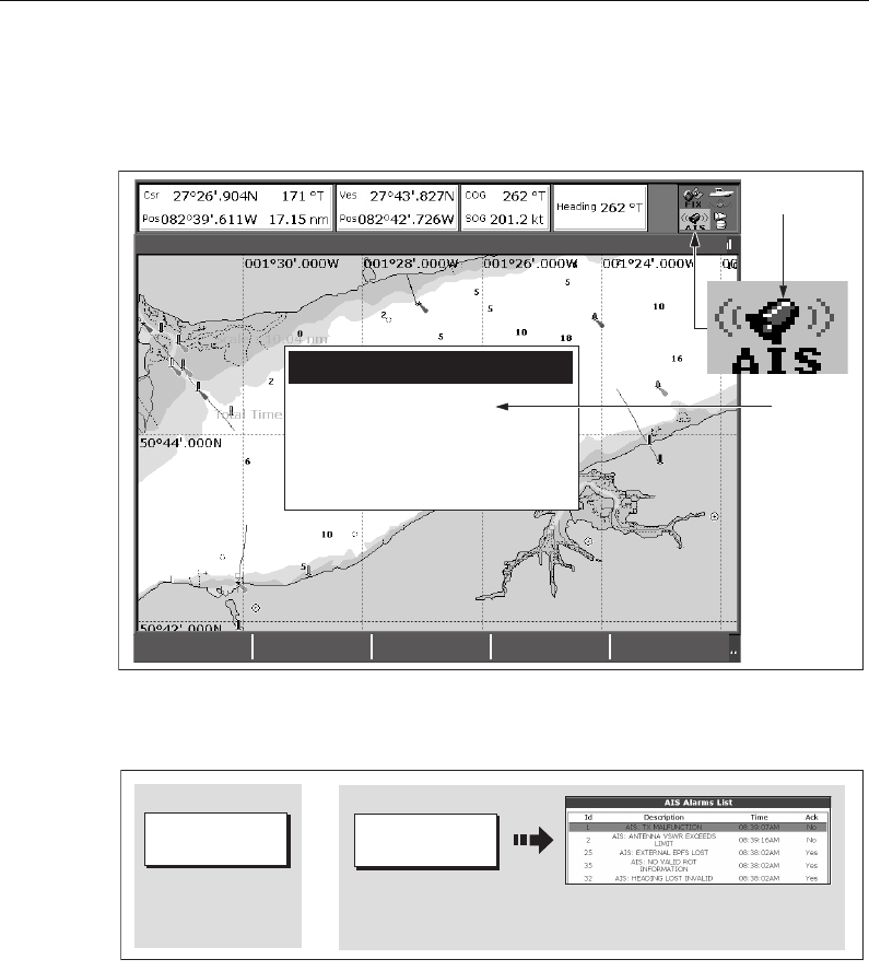
Chapter 11: Automatic Identification System (AIS) 175
Local AIS alarms
When the connected AIS unit generates an alarm, your C-Series displays a local alarm
message and indicates the alarm status in the data bar icon:
To proceed:
1. Remove the message pop-up/display active alarm list:
2. Acknowledge the message at your AIS unit.
Important: An alarm remains active until it is acknowledge on the AIS unit.
Active alarm list
The active alarm list shows the status of each local alarm. This list can either be
accessed via the AIS Layer Setup Menu (see
page 176
) or from the Alarms Setup Menu
(see
page 187
).
Note: The local AIS alarms must be acknowledged at the AIS receiver. Removing the
message or adding it to the Alarm list on your C-Series display does not cancel the
alarm.
REMOVE
MESSAGE
VIEW AIS
ALARM LIST...
4nm North-Up (Relative Motion) Local
AIS message
AIS Local Alarm
This alarm must be acknowledged on your
AIS Receiver.
To remove this message press REMOVE
MESSAGE.
"AIS message"
D8968_1
AIS Alarm
active icon
D8967_1
REMOVE
MESSAGE
Removes pop-up, adds alarm to and displays AIS Alarm List
Removes pop-up and
adds alarm to AIS
Alarm List.
VIEW AIS
ALARM LIST...
Or
81221_4.book Page 175 Tuesday, February 28, 2006 5:24 PM
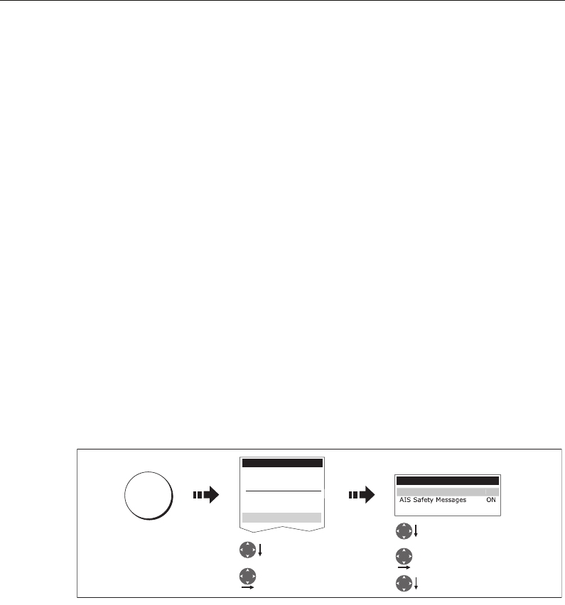
176 C-Series Display Reference Manual
11.8Simulator
We recommend that you use the simulator to familiarize yourself with the AIS function.
When the system simulator is switched on (see
page 184
), it displays 20 AIS targets
within a 25nm range. These targets are displayed using the appropriate AIS targets
status symbol (see
page 170
) and move around the screen as if they were real targets.
Important: Incoming safety messages cannot be displayed while the simulator is
switched on.
11.9AIS Layer Setup Menu
The AIS Layer Setup Menu allows you to:
• Select the target types displayed (ALL or DANGEROUS).
• Switch the dangerous and lost target alarm warning ON/OFF.
• Switch the display of AIS safety messages ON/OFF.
• View the list of active AIS unit alarms.
To display the AIS Layer Setup Menu:
1. Set the AIS LAYER status to ON ((see
page 169
).
2. Select the AIS Layer Setup:
D8969_1
AIS Layer Setup
AIS Alarms List...
D
isplayed Tar
g
et Type
s
All
Setup
Chart Setup...
Cartography Setup...
GPS Status...
Compass Setup...
AIS Layer Setup
Highlight AIS
Layer Setup
Select AIS
LayerSetup
MENU
Highlight required
option
Select option
Set/view as required
81221_4.book Page 176 Tuesday, February 28, 2006 5:24 PM
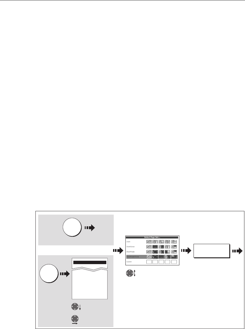
Chapter 12: System setup and customizing 177
Chapter 12: System setup and customizing
This chapter describes how to setup and customize your C-Series display. Any settings
that you change will be stored by the display and shown each time you power on. You
can, of course change these settings as many times as you wish.
12.1 Customizing the page sets
Each page set provides access to 5 different pages. Each page can display up to four
application windows.You can view multiple windows of the same application. For
example you could have two chart application on one page - one to view a large scale
chart, the other for a detailed view of your immediate surroundings.
If none of these meet your particular requirements you can edit the page sets to display
the application and page layout that suits your particular needs. This process should
also be used if you wish to run an engine monitor application.
In addition, you can rename of any of the page sets to a title that is more meaningful.
A control is also provided to reset the selected page set to the factory default
configuration.
Reconfiguring the application and page layout
To change the configuration of applications and/or page layout or switch off pages:
1. Select the edit page set option:
Highlight page set for
editing
Highlight Select
Page Set
Enter Select
Page Set
Press & hold
PAGE
D8675_2
EDIT PAGE SET....
Setup
Compass Setup...
Display setup...
Databar Setup...
Select Page Set....
System Diagnostics
Remove CF Card...
MENU
Or
81221_4.book Page 177 Tuesday, February 28, 2006 5:24 PM
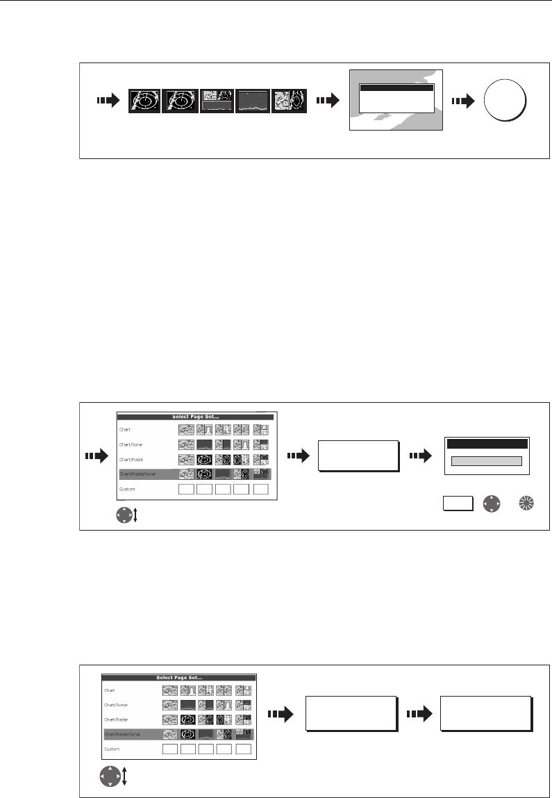
178 C-Series Display Reference Manual
2. Edit the page set:
The page, window and application layout that you have defined will now be available
each time you open the Select Page Set screen.
If you do not want to use all 5 pages in a page set, you can switch off individual pages.
When you use PAGE to cycle through the pages, the system will now skip any pages
that are set to OFF.
Note: A red cross will be overlaid on soft keys associated with pages set to OFF.
Rename a page set
If required, you can customize the names of the page sets:
1. Display the Select Page Set Menu, as described on
page 177
2. Rename the page set:
Return to default setting
To return a page set to the default configuration and name:
1. Display the Select Page Set Menu, as described on
page 177
.
2. Reset the page set to the default:
OK
Soft keys display pages
within selected page set
D8668_1
Edit Page Set
Follow the on-screen
instructions
Highlight page for renaming
D8669_2
RENAME PAGE
SET...
,
To make changes use:
or
Rename Page Set
Soft key
RESET TO
DEFAULT PAGES YES
Highlight page set to
return to default
D8709_1
81221_4.book Page 178 Tuesday, February 28, 2006 5:24 PM
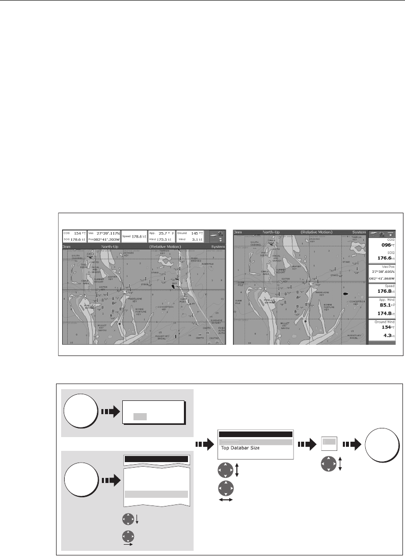
Chapter 12: System setup and customizing 179
12.2 Changing the databar
You can change the data bar to meet your own particular needs. This includes:
• Position - top or side.
• Size (top position only).
• Data displayed.
Note:
The databar configuration is a local setting and will therefore only affect the in-
dividual display on which you are working.
Databar position
The data bar can either be displayed vertically at the right-hand side of your screen or
horizontally across the top:
To change the data bar position:
Data bar size
When the data bar is positioned at the top of your screen, you have the option of
displaying the bar in either a Large or Normal format. The large bar provides more
data:
D8273_1
Top data bar Side data bar
D8272_1
Highlight Position
Select Position
DATA
Databar Setup Menu
Large
Configure...
P
o
s
i
t
io
n To
p
Press and hold
Side
To
p
Select
OK
Save
DATABAR
ON OFF
Highlight Data-
bar Setup
Select Data-
bar Setup
MENU
Or
Setup
System Setup...
Alarm Setup
Display Setup....
Databar Setup...
Select Page Set...
81221_4.book Page 179 Tuesday, February 28, 2006 5:24 PM
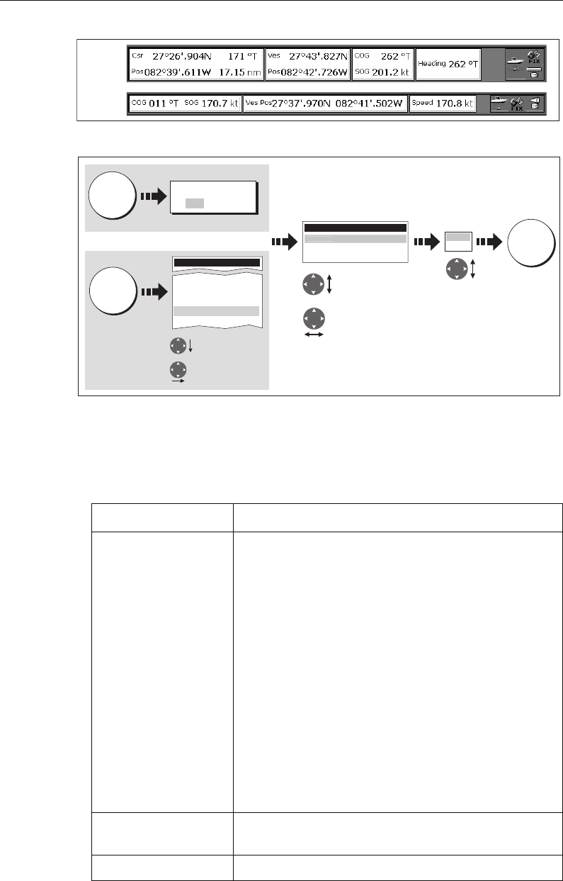
180 C-Series Display Reference Manual
To change the data bar size:
Customizing the contents of the data bar
You can customize your data bar so that it contains the particular information that you
require. The table that follows, shows the available data.
Data groups Data (abbreviations in brackets)
VESSEL Vessel position (Ves Pos)
Course over ground/Speed over ground (COG/SOG)
Heading
Speed
Wind velocity made good (VMG Wind)
Waypoint velocity made good (VMG Wpt)
Log trip*
Log
Trip
Ground Log/Trip 1
Ground Log
Ground Trip 1
Ground Trip 2
Ground Trip 3
Ground Trip 4
Rudder
NAVIGATION Cross track error (XTE)
Waypoint (WPT)
DEPTH Depth
D8274_1
Large
data bar
Normal
data bar
D8276_1
Normal
Large
Highlight Top
Databar Size
Select Top
Databar Size
DATA
Databar Setup Menu
Top Databar Size Large
Configure...
P
o
siti
o
n
T
o
p
Press and hold
Select
OK
Save
DATABAR
ON OFF
Highlight Data-
bar Setup
Select Data-
bar Setup
MENU
Or
Setup
System Setup...
Alarm Setup
Display Setup....
Databar Setup...
Select Page Set...
81221_4.book Page 180 Tuesday, February 28, 2006 5:24 PM
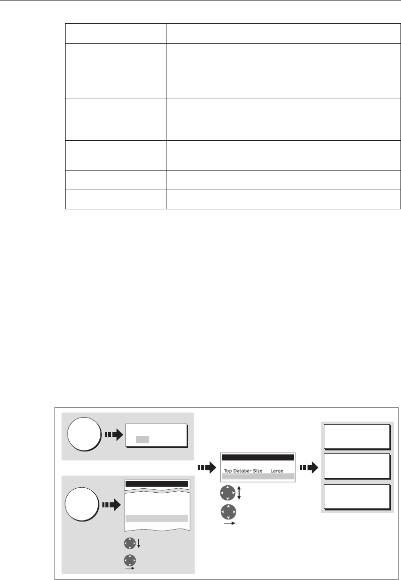
Chapter 12: System setup and customizing 181
* Trip log
You can view the total distance travelled (Log) and the distance since you last applied
a reset (Trip) based on your speed through water (STW).
In addition you can include in your data application or databar, ground log and four
ground trip counters based on your GPS position. These counters are updated every
minute.
If the GPS fix is lost or if the system simulator is switched on, the system will pause the
ground log and trip counters. When the GPS fix returns, or the system simulator is
switched off, the ground log land trip counters resume.
Selecting the configure options
To select the configure options for the data bar:
ENVIRONMENT Pressure
Air temperature (Air Temp)
Sea temperature (Sea Temp)
Set drift
WIND True wind
Apparent wind (App Wind)
Ground wind
TIME AND DATE Local time
Local date
CURSOR POSITION Cursor position (Csr Pos)
TRANSDUCER STATUS Transducer status
Data groups Data (abbreviations in brackets)
D8277_1
Databar Setup Menu
Position Top
C
onfi
g
ure..
.
ADD DATA...
REMOVE DATA...
MOVE DATA...
Highlight Configure
Select Configure
Select option
DATA
Press and hold
DATABAR
ON OFF
Highlight Data-
bar Setup
Select Data-
bar Setup
MENU
Or
Setup
System Setup...
Alarm Setup
Display Setup....
Databar Setup...
Select Page Set...
81221_4.book Page 181 Tuesday, February 28, 2006 5:24 PM
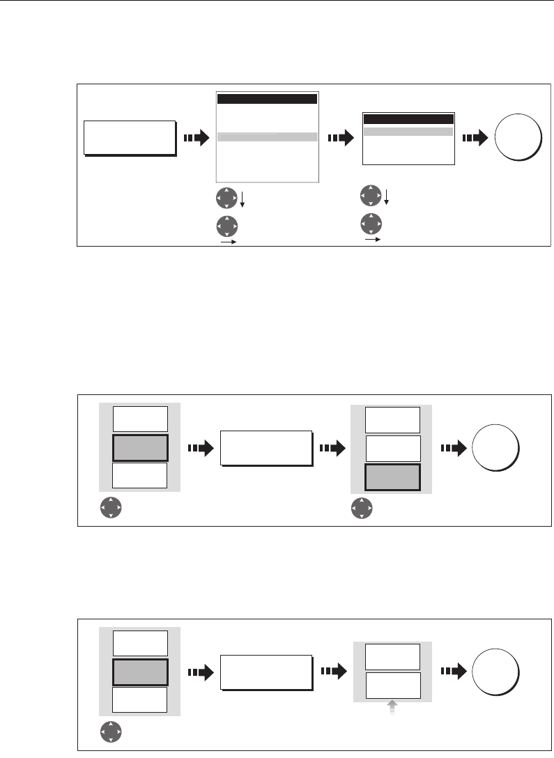
182 C-Series Display Reference Manual
Adding data
Once you have selected the configure option (see above), you can add new data:
When the data bar is positioned to the side of your screen, a new selection is added at
the top of the bar. When the data bar is positioned across the top of your screen, a new
selection is added on the left. Existing data moves down as new data is added.
Moving data
Once you have selected the configure option (see above), you can move data within
the bar.
Removing data
Once you have selected the configure option (see above), you can remove data within
the bar.
D8278_1
OK
Data Groups
VESSEL
NAVIGATION
DEPTH
WIND
TIME AND DATE
CURSOR POSITION
TRANSDUCER STATUS
ENVIR
O
NMENT
Add
selected
data
ADD DATA...
Data
Highlight required
Data Group
Select Data Group
Highlight required
Data
Select Data
Pressure
Air Temp
Sea Temp
Det Drift
D8279_1
OK
Save move
Highlight
data for moving
MOVE DATA...
Sea Temp
57.9oF
Air Temp
85.9oF
Speed
216.7kt
Sea Temp
57.9oF
Air Temp
85.9oF
Speed
216.7kt
Move data
D8280_1
OK
Save move
Highlight
data for moving
REMOVE DATA...
Sea Temp
57.9oF
Air Temp
85.9oF
Speed
216.7kt
Sea Temp
57.9oF
Speed
216.7kt
Boxes shuffle up
to fill space
81221_4.book Page 182 Tuesday, February 28, 2006 5:24 PM
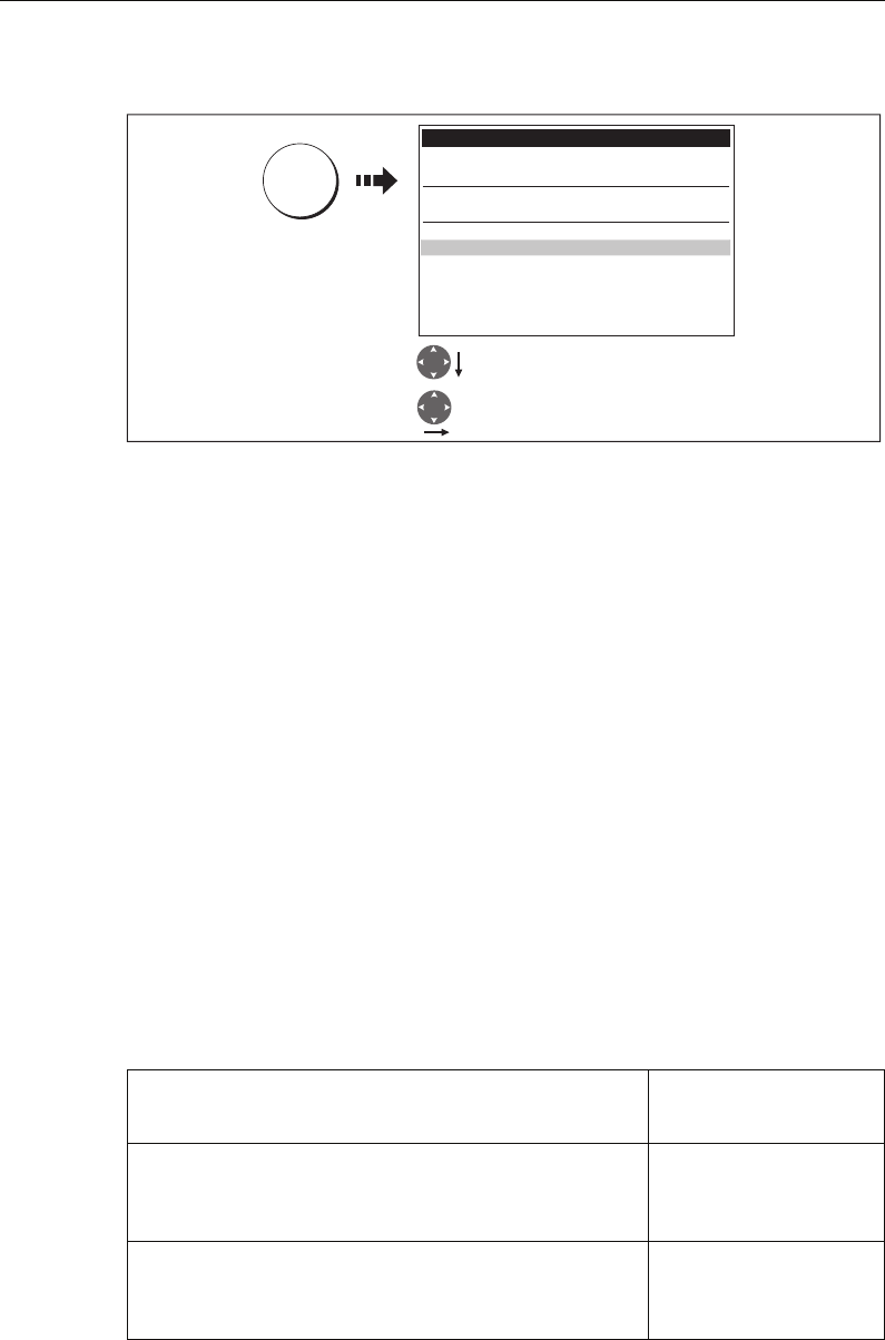
Chapter 12: System setup and customizing 183
12.3 Changing the set up menu options
The Setup Menu contains application specific and system-wide menus:
Application specific
These menus relate to the application for the active window i.e. Chart, Cartography,
Radar, Fishfinder and Engine Monitor Setup.
For further details please refer to the appropriate chapter.
External equipment menus
These menus provide options to set-up external equipment that is connected to your
system. They include AIS, Navtex, GPS and Compass setup.
The options that are available depend on what is connected to your system.
System-wide menus
These menus control functions throughout the system.
When you first power on your display the default values are used. The tables that
follow show the sub-menus, default settings and options available.
System Setup
MENU ITEM OPTIONS
(Default in bold)
Position Mode
Controls whether the position is expressed in latitude and lon-
gitude co-ordinates or Loran TDs.
Lat/Long
TD’s
TD Setup
If the
Position Mode
is set to TD’s, this function controls the
selected chain identifier, slave and ASF.
Various
MENU
D8281_1
Highlight required Setup Menu
Select Setup Menu
Setup
Chart Setup...
Cartography Setup
GPS Setup...
Compass Setup...
System Setup...
Alarm Setup...
Display Setup...
Databar Setup...
Select Page Set...
System Diagnostics...
Remove CF Card...
81221_4.book Page 183 Tuesday, February 28, 2006 5:24 PM

184 C-Series Display Reference Manual
Simulator
ON - allows operation of display without data from antenna
and/or external data sources.
Demo - a series of slides with descriptions to demonstrate the
various system functions.
OFF
ON
Demo
Bearing Mode
Mode of all bearing and heading data displayed. This does not
affect how the chart or radar are drawn.
True
Magnetic
MOB Data Type
Selects whether position data or dead reckoning displayed on
screen. Assuming your boat and the MOB are subject to same
tide and wind effects, dead reckoning normally gives a more
accurate course.
Dead Reckoning
Position
Variation Source
This allows you to compensate for the naturally occurring off-
set of the earths magnetic field. When set to AUTO, the value
the system would use (or is using) is noted in the menu e.g.
40W. To enter your own variation value, set to MANUAL.
Auto
Manual
Manual variation
If Variation Source is set to MANUAL then use this setting to
enter the variation value. This value is transmitted to any other
SeaTalk instruments.
0°E
Range 0 - 30º east/west
Language
Selected language used for screen text, labels, menus, options
and display format for lat/lon position information.
Selection available will
vary according to your
location.
Extended Character Set
Controls whether additional accented characters are made
available when you are entering text.
OFF
ON
Ground Trip Reset...
Resets the chosen ground trip distance counter to zero. Ground Trip 1 - 4 Reset
Settings Reset
Resets all system setup menus, including page sets and the data bar to the factory default.
Waypoints, routes and tracks are NOT removed.
Settings and Data Reset
Resets all system setup menus, including page sets and the data bar to the factory default.
Waypoints, routes and tracks are deleted.
Date /Time Setup See sub-menu below
Units Setup See sub-menu below
MENU ITEM OPTIONS
(Default in bold)
81221_4.book Page 184 Tuesday, February 28, 2006 5:24 PM

Chapter 12: System setup and customizing 185
Date/Time Setup Menu
Units Setup Menu
System Integration See sub-menu below
Waypoint Password Set-up...
Allows you to set up a password to protect access to your way-
point and route databases.
See
page 23
.
MENU ITEM OPTIONS
(Default in bold)
Date Format
Displays date as day/month/year or month/day/year
mm/dd/yy
dd/mm/yy
Time Format
Displays either 12 or 24 hour clock
12hr
24hr
Local Time Offset
Specify local time in increments of 0.5 hours (plus or minus
13) from the Universal Time Constant. Use rotary control for
0.5hr increments and trackpad to individually adjust the
value of the tens, units, and tenths - system rounds to the
nearest 0.5 hr.
+/- 13hrs from UTC
MENU ITEM OPTIONS
(Default in bold)
Distance Unit
Choose the units that you require distances to be displayed
in.
NM
Miles
km
Speed Units
Choose the units that you require speed to be measured in.
Knots
MPH
KPH
Depth Units
Choose the units that you require depths to be measured in.
Meters
Feet
Fathoms
Temperature Units
Select required temperate unit.
Fahrenheit
Celsius
MENU ITEM OPTIONS
(Default in bold)
81221_4.book Page 185 Tuesday, February 28, 2006 5:24 PM

186 C-Series Display Reference Manual
System Integration Setup Menu
Pressure Units
Select required pressure unit.
Bar
Psi
Kpa
Volume Units
Select required volume unit.
US Gallons
Imp Gallons
Litres
MENU ITEM OPTIONS
(Default in bold)
DSC Message
When set to ON, details of distress DSC messages are dis-
played on screen
ON
OFF
SeaTalk Alarms
When set to enabled, all SeaTalk system alarms are received
and displayed on the chartplotter.
Enabled
Disabled
Data Master
When set to ON, the display you are working on is defined as
the master.
ON
OFF
Bridge NMEA Heading
Used to prevent NMEA heading data being bridged onto the
SeaTalk bus. Switch this function off if you are using MARPA
with an external fast heading sensor.
ON
OFF
NMEA Output Setup
Allows you to switch off individual NMEA out sentences
APB, BWC, BWR, DBT, DPT,
GGA, GLL, MTW, RMA,
RMB, RMC, RSD, RTE, TTM,
VHW, VLW, VTG, WPL, ZDA
NMEA Port Setting
Select the appropriate setting dependent on the equipment
attached to the NMEA port for each individual display.
When Navtex 4,800 or 9,600 selected, the option to view
the Navtex message list is available.
NMEA 4,800
Navtex 4,800
Navtex 9,600
AIS 38,400
ST290 System
Select ON if your C-Series is connected to a SeaTalk2 system.
OFF
ON
SeaTalk2 Keyboard
Used to set up the SeaTalk2 keyboard with your Display.
When you are connecting a keyboard to your system select
ALL or ONE. When ONE selected press button on required
keyboard - display beeps to indicate keyboard selected.
OFF
ALL
ONE
MENU ITEM OPTIONS
(Default in bold)
81221_4.book Page 186 Tuesday, February 28, 2006 5:24 PM

Chapter 12: System setup and customizing 187
Alarm Setup Menu
The Alarm Setup Menu is divided into these sub-menus:
• System Alarms Setup.
• Navigation Alarms Setup.
• Radar Alarms Setup.
• Fishfinder Alarms Setup.
•AIS Alarms Setup.
Note: To silence any alarms, press
ACKNOWLEDGE.
System Alarms Setup
System alarms will sound in all applications.
MENU ITEM OPTIONS
(Default in bold)
Anchor Alarm
Switches the anchor alarm on or off.
OFF
ON
Anchor Alarm Radius
If the
Anchor Alarm
is set to ON, an alarm is triggered when you
drift from your anchor position by more than the specified dis-
tance.
0.01 - 9.99 nm
0.10nm
(or equivalent in the selected
Distance Unit
)
Timer
Switches the countdown timer alarm on or off
OFF
ON
Timer Period
If the
Timer
is set to ON, the system counts down from the time you
specify. An alarm is triggered when zero is reached.
00h01m - 99hrs 59mins
00h00m
Alarm Clock
Switches the alarm clock on or off.
OFF
ON
Alarm Clock Time
If the
Alarm Clock
is set to ON, an alarm is triggered when the time
you specify is reached.
00.01 - 24:00hrs
00:00
Temperature Alarm
If this alarm is set to ON, an alarm is triggered if the temperature
moves into or out of the range that you have specified in
Lower
Temperature Limit
/
Upper Temperature Limit.
OFF
ON
Lower Temperature Limit
Specifies the lower limit of the temperature range that is to trigger
the
Temperature Alarm
.
60°F
0°-99.8°F
Upper Temperature Limit
Specifies the upper limit of the temperature range that is to trigger
the
Temperature Alarm.
75°F
0.2°-99.9°F
81221_4.book Page 187 Tuesday, February 28, 2006 5:24 PM

188 C-Series Display Reference Manual
Navigation Alarms Setup
Navigation alarms will sound in any application when you are navigating.
Radar Alarms Setup
These alarms will only sound when you are in the radar application.
Note: If a radar is not detected, the alarm setup windows are greyed out.
Fishfinder Alarms Setup
MENU ITEM OPTIONS
(Default in bold)
Arrival Alarm Radius
The distance from the target waypoint or the closest point of
approach to the target waypoint that triggers the arrival
alarm to sound.
0.1nm
0.01 - 9.99nm
Offtrack Alarm
Switches the off-track alarm on or off
OFF
ON
Offtrack Alarm XTE
If the
Offtrack Alarm
is set to ON, an alarm is triggered when
the XTE for any current navigation, exceeds the value that
you have specified.
0.3nm
0.01 - 9.99nm
(or equivalent in the
selected
Distance Unit
)
MENU ITEM OPTIONS
(Default in bold)
Guard Zone Sensitivity
Ensure that this is not set too low or targets will be missed.
50%
0 - 100%
MENU ITEM OPTION
(Default in bold)
Fish Alarm
Switches the fish alarm on or off.
OFF
ON
Fish Alarm Sensitivity
If the
Fish Alarm
is set to ON, an alarm is triggered when the
fish return strength reaches the sensitivity that you specify.
5%
10% - 100%
Fish Alarm Depth Limits
If the
Fish Alarm
and this alarm is set to ON, an alarm is trig-
gered (2 beeps) if any target meets the sensitivity level and
is within the
Shallow Fish Limit
and
Deep Fish Limit
that you
specify.
OFF
ON
Shallow Fish Limit
Specifies the lower value for the
Fish Alarm Depth LImit
.
2ft
(0002ft - 1000ft)
81221_4.book Page 188 Tuesday, February 28, 2006 5:24 PM
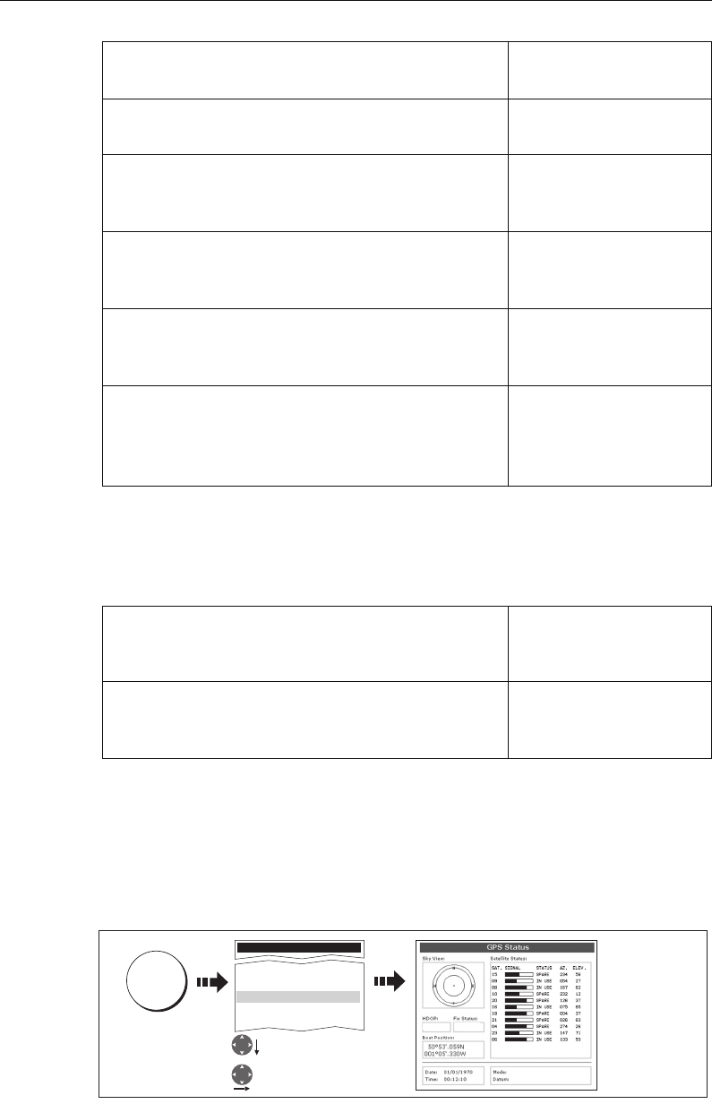
Chapter 12: System setup and customizing 189
Note: If a fishfinder is not detected, the alarm setup windows are greyed out.
AIS Alarms Setup
GPS Status
The GPS is used to position your boat on the chart. You can set up your Global
Positioning System (GPS) and check its status using the GPS status icons and the GPS
Status page of the Setup menu.
To access the GPS Status page:
Deep Fish Limit
Specifies the upper value for the
Fish Alarm Depth LImit
1000ft
(0002ft - 5000ft)
Shallow Depth Alarm
Switches the shallow depth alarm on or off.
If a DSM is not connected, this cannot be set.
OFF
ON
Shallow Depth Alarm Value
If the
Shallow Depth Alarm
is set to ON, an alarm is trig-
gered if the depth drops below the value you specify.
5ft
(0002ft - maximum range of
transducer)
Deep Depth Alarm
Switches the deep depth alarm on or off.
If a DSM is not connected, this cannot be set.
OFF
ON
Deep Depth Alarm Value
If the
Deep Depth Alarm
is set to ON, an alarm is triggered if
the depth exceeds the value that you specify.
3000 ft (DSM with 600W
transducer attached)
5000 ft (DSM with 1kW
transducer attached)
Dangerous Targets Alarm
Switches the alarm for dangerous targets to on or off. When
OFF, the AIS alarm off icon is displayed in the status bar.
OFF
ON
AIS Alarm List
Details the identity, description, time and acknowledge-
ment of alarm messages received from an AIS receiver.
See “AIS Alarms” on
page 174.
MENU ITEM OPTION
(Default in bold)
Setup
System Setup...
Alarm Setup
GPS Setup....
Compass Setup...
Display setup...
Highlight GPS Setup
Select GPS Setup
D8710_1
MENU 0
0
0
0
0
0
0
0
0
0
0
00001.0
SD-FIX
1.0
SATELLITE DIFFERENTIAL
WGS 1984
81221_4.book Page 189 Tuesday, February 28, 2006 5:24 PM
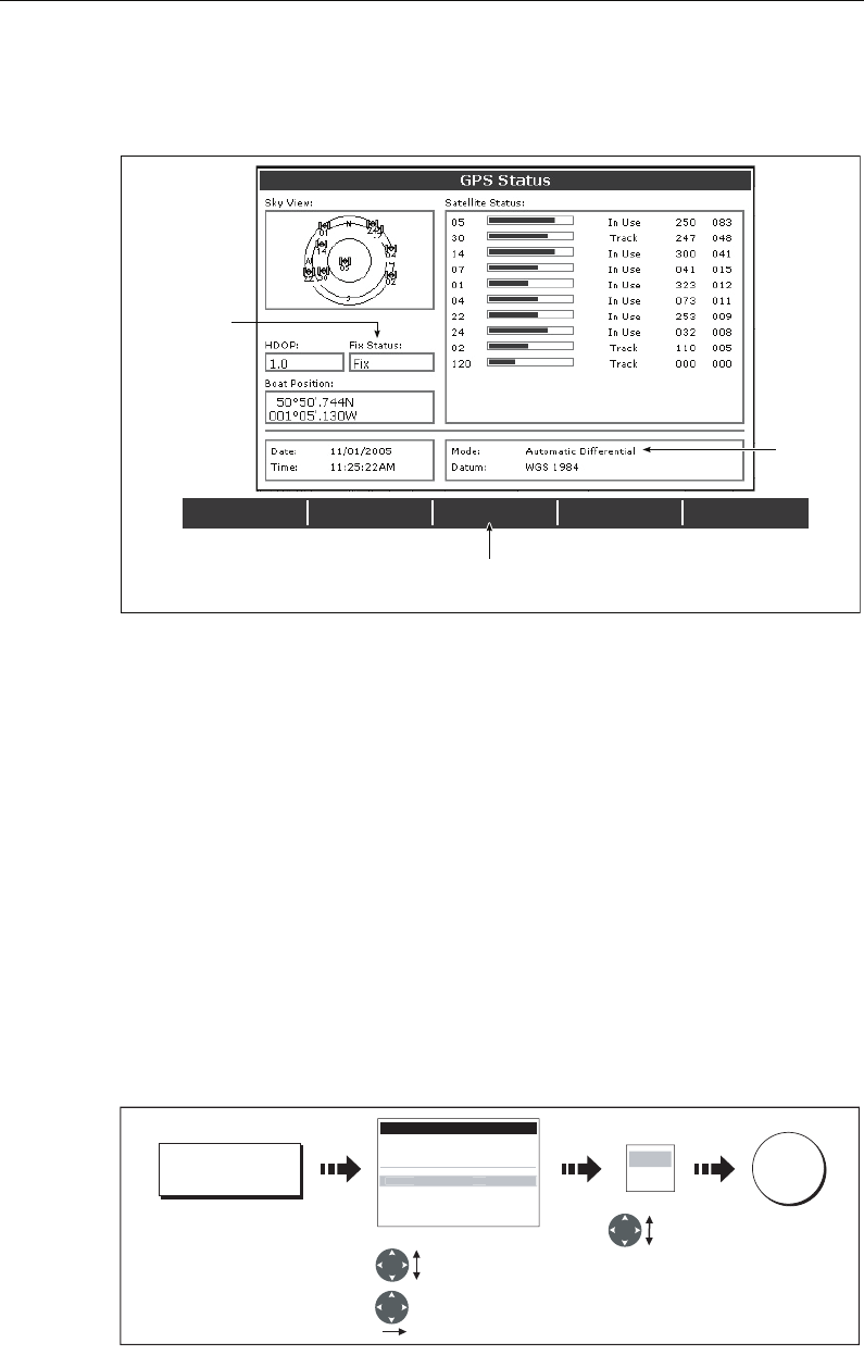
190 C-Series Display Reference Manual
This screen provides, for each tracked satellite, the satellite number, a graphical signal
strength bar, status, azimuth angle and its elevation angle from your vessel. The sky
view graphic shows the position of these satellites.
Positional accuracy is dependent upon these parameters; in particular, the azimuth
and elevation angles are used in a triangulation process to calculate your position.
Horizontal Dilution of Position (HDOP) is a measure of this accuracy; a higher figure
signifies a greater positional error. In ideal circumstances, the figure should be in the
region of 1.0.
Selecting the satellite differential system
You should select the satellite group(s) appropriate to your area, via the Other Set Up
soft key:
• WAAS - United States
• EGNOS - Europe
• MSAS - Japan
•GAGAN - India
Note: The EGNOS, MSAS and GAGAN systems may not currently be active. Check with
your local government for operational status.
DIFF SET UP OTHER SET UP RESTART GPS
DIFF GPS
ON OFF
D6809_3
Actual mode
GPS reporting
(No Fix, Fix, D
Fix or SD Fix)
Mode
selected
by GPS
Only available if connected to
Raymarine landbased GPS e.g. 114
DIFF SET UP
D8715_1
GPS Setup Menu
Datus WGX 1984
COG/SOG Filter Medium
EGNOS OFF
MSAS OFF
GAGAN OFF
WAA
S
ON
Highlight satellite
group
Highlight
ON or OFF as
appropriate
Select group
OK
ON
OFF
OTHER SET UP
81221_4.book Page 190 Tuesday, February 28, 2006 5:24 PM
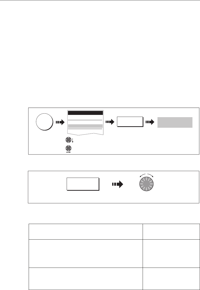
Chapter 12: System setup and customizing 191
Selecting the COG/SOG filter
The COG/SOG filter should be set to the level appropriate to your boat’s use and to the
level of oscillation being experienced by the GPS:
• HIGH - for use when trawling or when there is a high level of oscillation.
• MEDIUM - for general use
• LOW - for use when travelling at speed
Compass Setup
This option can be used to linearize a Raymarine ST80 active compass or Smart
Heading sensor connected on SeaTalk. To linearize (‘swing’) your compass proceed as
follows:
1. Select the LINEARIZE COMPASS option:
2. When instructed to align heading:
Display Setup
MENU OPTION OPTIONS
(Default in bold)
Soft key Autohide
Controls whether the soft key bar is automatically hidden if
not used for a period of 10 seconds. Pressing any key re-
displays the soft key bar.
OFF
ON
Cursor Autohide
Controls whether the cursor is automatically hidden if not
used for 10 seconds. Pressing any key re-displays the cursor.
OFF
ON
LINEARIZE
COMPASS
Follow on screen
instructions
Highlight Compass
set up
Select Compass set up
D8670_1
MENU
Setup
Radar Setup...
GPS Status...
Compass Setup...
System Setup...
ALIGN HEADING
Turn one click at a time
to fine tune heading
D6871_1
81221_4.book Page 191 Tuesday, February 28, 2006 5:24 PM

192 C-Series Display Reference Manual
Databar Setup
This sub-menu accesses the Configure Data Bar Menu - refer to
page 179
for full
details.
Select Page Set
This sub-menu accesses the Select Page Sets Menu. For details of how to reconfigure
the page sets, please see
page 177
.
System Diagnostics
This sub-menu is for diagnostic use by authorized dealers.
Remove CF Card
This sub-menu allows you to safely remove the Compact Flash card that is currently in
use.
CAUTION: Improper use of this setting may cause loss of data or damage to
the card. Ensure you have read the instructions on
page 18
thoroughly before
attempting to remove or insert a CF card.
Key beep
Controls whether a noise is made when you press a key.
OFF
ON
Text size
Controls the size of the text on the screen
Small
Large
MENU OPTION OPTIONS
(Default in bold)
81221_4.book Page 192 Tuesday, February 28, 2006 5:24 PM

Chapter 13: Maintenance & Troubleshooting 193
Chapter 13: Maintenance & Troubleshooting
13.1 Introduction
This chapter provides information on maintaining and troubleshooting your C-Series
Display, and also information on how to get assistance from Raymarine.
13.2 Maintenance procedures
At regular intervals, carry out the following servicing procedures:
• Routine checks.
• Cleaning the Display.
Do not attempt any other servicing procedures.
Servicing and Safety
• Raymarine equipment should be serviced only by authorized Raymarine service
technicians. They will ensure that service procedures and any replacement parts
used will not affect performance. There are no user serviceable parts in any Rayma-
rine product.
• Some products generate high voltages, so never handle the cables or connectors
when power is being supplied to the equipment.
• When powered on, all electrical equipment produces electromagnetic fields. These
can cause adjacent pieces of electrical equipment to interact with one another,
with a consequent adverse effect on operation. In order to minimize these effects
and enable you to get the best possible performance from your Raymarine equip-
ment, guidelines are given in the installations manual, to enable you to ensure min-
imum interaction between different items of equipment, i.e. ensure optimum
Electromagnetic Compatibility (EMC).
• Always report any EMC-related problem to your nearest Raymarine dealer. We use
such information to improve our quality standards.
• In some installations, it may not be possible to prevent the equipment from being
affected by external influences. Generally this will not damage the display, but it
can lead to spurious re-setting action, or momentarily may result in faulty operation.
• At the end of the useful working life of this product, it should disposed of in accor-
dance with local regulations.
Routine checks
Carry out the following tasks on a regular basis:
• Examine all cables for signs of damage, such as chafing, cuts or nicks.
• Check that all cables are securely connected.
81221_4.book Page 193 Tuesday, February 28, 2006 5:24 PM

194 C-Series Display Reference Manual
Cleaning the display
CAUTION: Cleaning the display
Take care when cleaning the display, to avoid damaging it.
(1) Do NOT wipe the display screen with a dry cloth, as this could scratch
the screen coating.
(2) Do NOT use acid, ammonia based or abrasive products.
Regularly clean your Display as follows:
1. Switch off the power to the Display.
2. Wipe the Display with a clean soft cloth. To remove oily finger marks use a spray
cleaning agent of the type used for cleaning eyeglasses.
A suitable micro-fibre cloth is supplied with your display and spray can be purchased
from your local optician.
13.3 Resetting the Display
You can reset the C-Series Display in several ways:
• Settings reset.
• Settings and data reset.
Settings reset
All system set-up menus, including page sets and the data bar are reset to the factory
default, when you apply a settings reset. Your waypoints, routes and tracks are NOT
removed.
Applying a settings reset
To apply a settings reset:
The system resets and returns you to the power on procedure.
D8662_1
MENU
Highlight System
Setup menu
Select System
Setup menu
Position mode...
ID Setup...
Simulator...
Bearing Mode...
MOB Data Type...
Manual Variation...
Language...
Extendeded Charater Set...
Ground Trip Reset
Settings And Data Reset
Lat/Long
ON
True
Position
Auto (01oE)
00oEnglish (US)
OFF
System Setup Menu
S
ettin
g
s Rese
t
Highlight Settings Reset
Select settings
reset
Yes
Setup
Radar Setup...
GPS Status...
Compass Setup...
S
y
stem Setu
p
..
.
81221_4.book Page 194 Tuesday, February 28, 2006 5:24 PM
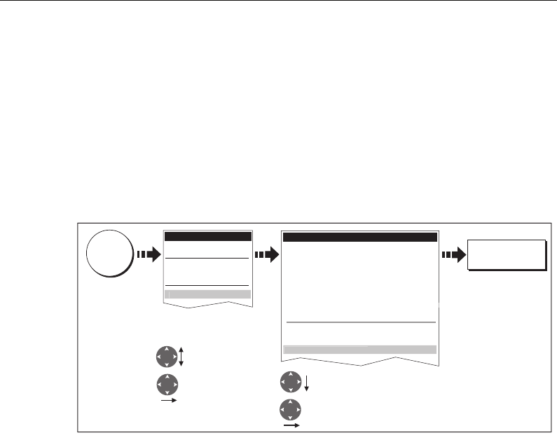
Chapter 13: Maintenance & Troubleshooting 195
Settings and data reset
All data set-up menus, including page sets and the data bar, are reset to the factory
default when you apply a settings and data reset.
Important: Applying a settings and data reset will remove all waypoints, routes and
tracks.
Applying a settings and data reset
To carry out a settings and data reset:
The system resets and returns you to the power on procedure.
13.4 Troubleshooting your Display
All Raymarine products are, prior to packing and shipping, subjected to
comprehensive test and quality assurance programs. However, if your C-Series Display
unit should develop a fault, this section will help you to identify the most likely cause
and show the corrective action required to restore normal operation.
If, after referring to this section, you are still having problems with your Display, contact
your local dealer, national distributor or Raymarine Technical Services Department for
further advice.
Always quote the product serial numbers which are printed on the back of the unit.
Common problems and how to solve them
This section is divided into problems associated with:
• Installation/Display.
• Chart application.
• Fishfinder application.
• Radar application.
D8663_1
MENU
Highlight System
Setup menu
Select System
Setup menu
Position mode...
ID Setup...
Simulator...
Bearing Mode...
MOB Data Type...
Manual Variation...
Language...
Extendeded Charater Set...
Ground Trip Reset
Settings Reset
Lat/Long
ON
True
Position
Auto (01oE)
00oEnglish (US)
OFF
System Setup Menu
Settin
g
s an
d
Data Rese
t
Highlight settings
and data reset
Select settings
and data reset
Yes
Setup
Radar Setup...
GPS Status...
Compass Setup...
S
ystem
S
etup..
.
81221_4.book Page 195 Tuesday, February 28, 2006 5:24 PM

196 C-Series Display Reference Manual
Installation/Display
Problem
Solution
Display does not power up
• Check power supply cable is sound and that all connections are tight and free from corrosion.
•Check relevant fuses.
• Check power source is of the correct voltage and sufficient current.
My display switches off
• Check power input connection is secure at the rear of the Display(s).
• Check power cable for damage or corrosion.
• Check your boat’s power supply for faulty connections or insufficient cable diameter.
How do I upgrade my Display software?
Visit www.raymarine.com and click on Support to download the latest software. Follow the instruc-
tions included with these downloads.
How do I reset my display?
Via the system setup menu. For details see page
page 194
.
Display very dull/hard to view
• Check PALETTE set to DAY (see
page 16
).
• Check backlight level (see
page 16
).
No fix displayed against GPS status icon
•Check GPS status (see
page 189
).
• Check the GPS antenna has a clear view of the sky.
• Check connections/operation of the GPS antenna.
No instrument navigational or engine data displayed
• Check instruments/engine interface are operating correctly.
• Check SeaTalk/NMEA correctly connected to Display (see System Integration chapter of the Instal-
lation Guide).
• Check all SeaTalk/NMEA cables are free from damage and corrosion.
81221_4.book Page 196 Tuesday, February 28, 2006 5:24 PM

Chapter 13: Maintenance & Troubleshooting 197
Chart
Fishfinder
Problem
Solution
Vessel not shown in correct geographical position on Display
• Check GPS status (
page 189
).
• Check that the Display is not in Simulator mode (see
page 184
).
• Check the SDGPS setting is switched OFF.
• Perform the chart offset operation (see
page 91
).
Display does not show enough chart detail
• Check that the chart card for the appropriate area is installed.
• Set the Declutter option to OFF (see
page 89
).
• In the Cartography Setup Menu switch the appropriate feature(s) to ON.
Display will not read chart correctly
• Check the Chart Card has been inserted correctly with the display switched off.
• Check this is the correct compact flash cartography for the unit.
Problem
Solution
How do I upgrade my DSM software?
Visit www.raymarine com and click on Support to download the latest software. Follow the instruc-
tions included with these downloads.
‘No data source’ for my fishfinder
• Check the DSM power cable is free from damage and corrosion.
• Check DSM is receiving the correct voltage and current.
• Check status LED of the DSM unit - refer to Maintenance and problem solving section of the DSM
owner’s handbook.
• Check the DSM’s connections are sound and connected correctly - refer to the System Integration
chapter of your C-Series Installation Guide.
No depth readings available from the DSM
• Check status LED of DSM unit - refer to the Maintenance and Problem solving section of your DSM
Owner’s manual
• Check Gain setup and Transducer frequency - refer to the Fishfinder chapter in your Reference Man-
ual.
• Check the DSM power cable is free from damage and corrosion
81221_4.book Page 197 Tuesday, February 28, 2006 5:24 PM

198 C-Series Display Reference Manual
Radar
13.5 Getting Technical Support
This section details how you can obtain technical support for your C-Series display or
for your Navionics cartography.
Raymarine provides a comprehensive customer support service, on the world wide
web, through our worldwide dealer network and by telephone help line. If you are
unable to resolve a problem, please use any of these facilities to obtain additional help.
Help us to help you
When requesting service, please quote the following product information:
•Product name.
• Product identity.
• Serial number.
• Software application version.
To access this information:
Problem
Solution
‘No data’ message
• Check that cable connecting the scanner to the Display is securely connected and undamaged.
‘Scanner software incompatible’ message
• Check software revisions by contacting your local Raymarine dealer.
“Invalid scanner software: Version xx.x, Version xx.x required”
Incorrect software version installed. Contact your local Raymarine dealer.
“Scanner not responding” message
Check that the cable connecting the scanner to the radar display unit is securely connected and
undamaged.
“Open array cannot be powered from the display”
Scanner not compatible with C-Series Display - refer to
Important Information
Section of this manual.
“Scanner hardware fault”
Scanner not functioning -
refer to Chapter 4 - Maintenance & Troubleshooting
of this manual.
The bearing displayed on the radar picture is not the same as the actual bearing
Perform the bearing alignment procedures described in the Installation Guide.
81221_4.book Page 198 Tuesday, February 28, 2006 5:24 PM
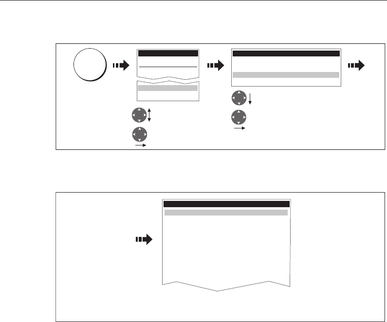
Chapter 13: Maintenance & Troubleshooting 199
1. Select the Software Services menu:
2. Note down the Product Name and ID, Serial Number and App Version from the
menu:
World wide web
Please visit the Customer Support area of our website at: www.raymarine.com
Visit the Customer Support area of our website for Frequently Asked Questions,
servicing information, e-mail access to the Raymarine Technical Support Department
and details of Raymarine agents, worldwide.
If you don’t have access to the world wide web, contact Technical Support where
specialists are available to answer questions about installing, operating and trouble-
shooting all Raymarine products.
Contacting Raymarine in the US
You can contact Raymarine in the US either using the Raymarine world wide web as
detailed above or by calling one of the telephone numbers below.
For accessories and parts
Contact your authorized Raymarine dealer or Raymarine Technical Services on:
1-800-539-5539 extension 2333 or (603)-881-5200
Opening hours: Monday through Friday 0815 - 1700, Eastern Standard or Eastern
Daylight Savings Time.
D8665_1
MENU
Setup
Highlight System
Diagnostics menu
Select System
Diagnostics menu
System Diagnostics
Highlight software
services
Select software
services menu
Radar Setup...
GPS Status
System Diagnostics...
Remove CF Card...
External Interfaces.....
Internal Interfaces.....
Software Services....
D9103_1
Unit Info : Software Details
Product Name
Product Family
Product ID
Serial Number
Bootcode Version
World Map Version
App Version
App Build Time
App Build Label
App Build Machine
C120 Display
C Series
D598
Serial no.xxxxxxxxxx
v0.06
v1.00
v3.99
Thu 22 Sep 2005 08:09:05
GMT
Development build
Full details of your particular unit and its
software displayed.
81221_4.book Page 199 Tuesday, February 28, 2006 5:24 PM

200 C-Series Display Reference Manual
For product repair and service
In the unlikely event that your Raymarine unit should develop a problem, contact your
authorized Raymarine dealer for assistance. The dealer is best equipped to handle your
service requirements and can offer timesaving help in getting your equipment back
into normal operation.
If repairs cannot be obtained conveniently, product service can be obtained by
returning the unit to:
Raymarine Inc.
21 Manchester Street
Merrimack, NH,
03054 - 4801
US
1-800-539-5539
The Product Repair Centre is open Monday to Friday 0815 to 1700 Eastern Standard
Time or Eastern Daylight Savings Time.
All products returned to the Repair Centre are registered upon receipt and a
confirmation letter is sent to acknowledge the repair status and the reference number
of the product.
We will make every effort to carry out the repair and return your unit as quickly as
possible.
If you wish to enquire about the repair status of your unit, contact the Repair Centre at:
1-800-539-5539
Contacting Raymarine in Europe
You can contact Raymarine in Europe either using the Raymarine world wide web as
detailed above or by calling the telephone number below
For technical support, service and accessories:
Contact your authorized Raymarine dealer or Raymarine Technical Support at:
Anchorage Park
Portsmouth
P03 5TD
England
Tel: +44(0)23 92714713
Fax: +44(0)23 92661228
81221_4.book Page 200 Tuesday, February 28, 2006 5:24 PM

Chapter 13: Maintenance & Troubleshooting 201
For Navionics cartography
For questions about cartography, please contact Navionics directly through their web
site:
www.navionics.com
or contact Navionics customer support:
If you wish to file a report of an error or omission on a Navionics chart, please provide
the information to Navionics web site, Discrepancy Report section at the link below:
http://www.navionics.com/DiscrepancyReports.asp
Navionics customer support
Navionics Italy Via Fondacci, 269
Z.I. Montramito
55054 Massarosa Italy
Tel: +39-0584-329111
Fax: +39-0584-962696
sales@navionics.it
Navionics USA 6 Thatcher Lane
Wareham
MA 02571 USA
Toll Free: 800-848-5896
Tel: 508-291-6000
Fax: 508-291-6006
sales@navionics.com
Navionics Australia 134/85 Reynolds Street
Balmain
NSW 2041 Australia
Tel: +61-2-9555-2522
Fax: +61-2-9555-2900
sales@navionics.com.au
Navionics UK PO Box 38
Plymouth, PL9 8YY
England
Tel: +44-1752-204735
Fax: +44-1752-204736
sales@navionics.co.uk
81221_4.book Page 201 Tuesday, February 28, 2006 5:24 PM

202 C-Series Display Reference Manual
81221_4.book Page 202 Tuesday, February 28, 2006 5:24 PM

Appendix A: Specification 203
Appendix A:Specification
C70, C80 and C120 LCD Color Displays
General
Approvals:
CE
FCC Conforms to essential requirements of 1995/5/EC, 1989/336/EC.
Compliant with CFR47 Parts 2 & 80
Size:
C70
C80
C120
253 x 175 x 110 mm (9.9 x 6.9 x 4.3 in.) excluding bracket
283 x 210 x 110 mm (11.1 x 8.2 x 4.3 in.) excluding bracket
356 x 264 x 114 mm (14.0 x 10.4 x 4.5 in.) excluding bracket
Weight:
C70
C80
C120
1.2 kg. (2.6 lbs)
1.8 kg. (3.9 lbs)
3.0 kg. (6.6 lbs)
Mounting Bracket with panel mount option
Supply voltage 12V or 24V DC nominal (10.7-32V DC maximum)
Floating earth/ fully isolated
Power consumption:
C70
C80
C120
9 W (full brightness)
10 W (full brightness)
12 W (full brightness)
Environmental:
Op/Storage Temp. Range
Humidity limit
Waterproof to CFR46; suitable for external mounting
-10° C to +50° C
up to 95% at 35°C non-condensing
Controls 9 defined keys, 5 soft keys, trackpad and rotary control
Cursor Context sensitive, provides range/bearing or lat/lon or depth/range
on fishfinder
Display type Color TFT LCD
Resolution:
C70
C80
C120
640 x 480 pixels (VGA)
640 x 480 pixels (VGA)
800 x 600 pixels (VGA)
Display size:
C70
C80
C120
6.5 in
8.4 in
12.1 in
Display Windows Chart, Radar, Fishfinder, CDI, Data and Engine Monitor
Illumination Screen and keypad: 0 to 100% in 64 steps
Day and Night color palettes available
Languages The selection available will vary according to your location.
System Alarms Alarm clock, Anchor, Arrival, Deep depth, MOB, Offtrack, Shallow
depth, Temperature, Timer
81221_4.book Page 203 Tuesday, February 28, 2006 5:24 PM

204 C-Series Display Reference Manual
Connectors 13 pin Radar scanner
4 pin DSM
3 pin SeaTalk
5 pin NMEA
5 pin SeaTalk2/ NMEA2000
3 pin Power
Interfaces Pathfinder Radar scanner
1 x DSM receive
1 x SeaTalk, receive and transmit
1 x NMEA0183, receive and transmit
1 x SeaTalk2/ NMEA2000
CompactFlash card slot
Waypoints 1000 waypoints entered via cursor, lat/lon, range and bearing from
present position or at boat’s position.
16 character name can be assigned.
Waypoint symbols and groups
Additional storage available on CompactFlash cards
Waypoint Transfer Waypoints database via NMEA and CompactFlash cards. Software
also available to convert waypoints to Excel file.
Man Overboard (MOB Mode) Mark placed with course line; readout shows range, bearing, lat/
lon of MOB and time elapsed since MOB
Screen functions Full, half and quarter screens available dependant on function.
Also 3 window page with 2 x 1/4 page windows and 1 x 1/2 page
window
Information Displayed in horizontal or vertical data bar and includes boat data,
navigation data, depth, environmental data and wind data
General
81221_4.book Page 204 Tuesday, February 28, 2006 5:24 PM

Appendix A: Specification 205
Radar Features
Range Scales (Range Rings) 1/8 (1/16)nm to 72 (12) nm dependant on scanner
Performance limited by scanner type and position.
Range Ring Accuracy Better than +/- 1.5% of the max. range scale in use, or 22m (72 ft),
whichever is the greatest.
Bearing accuracy +/- 1°
Variable Range Markers 2 x VRM’s, readout nm, sm, km
Electronic Bearing Lines 2 x EBL’s, floating if required, resolution 1°
Bearing scale 360° graduated at 10° intervals
2° small ticks
10° large ticks
Minimum range 23m (25 yds)
Range Discrimination 23m (25 yds)
Presentation Modes Head up, Course up or North up (selectable True or Magnetic)
Relative or True Motion
Scanner Control Interference rejection, standby/transmit modes, pulse selection,
Tune, Rain, FTC and Sea controls, with selection of manual or
automatic control of gain, sea clutter and tune (Auto GSTTM)
Magnetic Sensor NMEA (required for fast heading data, suitable for MARPA), or
SeaTalk
Waypoint Display Target waypoint displayed with User control of symbols and
groups
MARPA Manual acquisition of 10 targets, automatic tracking, dangerous
target alarms, safe zone, target history, true or relative vectors,
CPA graphics and indication of target speed/course, bearing/
range, CPA and TCPA.
Variation Source Auto (SeaTalk/NMEA/Internal algorithm) or Manual
Guard Zone Alarm 2 guard zones, selectable sensitivity level, audible alarm
Off centre function In Relative Motion, 66% of radius (except at max. range)
Wakes 10s, 30s, 1 min, 5 min, 10 min, OFF
Target Expansion Operator selectable with 2 levels available, OFF
Timed TX Rotation periods: 10, 20 or 30 scans
Repetition periods: 3, 5, 10 or 15 minutes
AIS overlay Switch AIS symbols on/off. Specify range and display heading/
speed vectors and ROT. View detailed AIS data, safety critical tar-
get data, ALR and SRM messages. Set up a safe zone.
81221_4.book Page 205 Tuesday, February 28, 2006 5:24 PM

206 C-Series Display Reference Manual
Chart Features
Cartography Navionics Charts on CompactFlash cards
Chart of the world built in
Chart scaling 1/64nm (if cartographic detail is available to 4000nm
Presentation Modes Head up, Course up or North up (selectable True or Magnetic)
Relative or True Motion
Waypoints 1000 waypoints entered via cursor, lat/lon, range and bearing from
present position or at boats position.
16 character name can be assigned.
Waypoint symbols and groups
Additional storage available on CompactFlash cards
Waypoint Transfer Waypoints database via NMEA
Routes A route plan may contain up to 50 waypoints. Up to100 routes can
be stored in the units internal memory.
Additional storage available on CompactFlash cards.
SmartRoute to create a route from track history.
Track History 10 tracks with up to 1000 points in each can be stored in the units
internal memory. Track optimisation reduces number of points
used. Additional storage available on CompactFlash cards
Alarms Programmable waypoint arrival, cross track error, anchor alarm,
anchor drift, position fix/data loss warning, countdown timer and
alarm clock.
Navigation information Own boats position in lat/lon, XTE, TTG and SOG/COG selectable.
Bearing and distance to waypoint. Bearing and distance to cursor
and ETA.
Variation Source Auto (SeaTalk/NMEA/Internal algorithm) or Manual
AIS overlay Switch AIS symbols on/off. Specify range and display heading/
speed vectors and ROT. View detailed AIS data, safety critical tar-
get data, ALR and SRM messages. Set up a safe zone.
Radar/Chart overlay Radar image can be overlaid on all screen charts
Fishfinder features
Transducer Transom-mount, in-hull or thru-hull
Output power:
Standard transducer
High performance transducer Adjustable to 600 watts RMS
Adjustable to 1000 watts RMS
Frequency Dual 50 kHz and 200 kHz
Pulse length 100 usec to 4 msec
Maximum Transmit Rate 1580 pulses/ min at 50 ft range
Depth:
Standard transducer
High performance transducer 3 ft (1m) to 3000 ft (1000m)
3 ft (1m) to 5000 ft (1700m)
Alarms Fish alarm, fish alarm depth, shallow and deep fish limit
81221_4.book Page 206 Tuesday, February 28, 2006 5:24 PM

Appendix A: Specification 207
Data features
Engine monitor features
Visit www.raymarine.com for a list of compatible engines.
Navtex features
AIS features
Interfacing
Panel type 5 panels available. Pre-defined (Navigation, Waypoint, Route,
Fishing or Sailing) or user-configured.
Data available Vessel position, active waypoint, TTG, VMG - Waypoint, depth,
COG SOG, heading, speed, set/drift, trip, log, ground log, ground
trip, rudder, local time and date, sea temperature, app wind, true
wind, VMG wind, ground wind, XTE, compass, locked heading,
waypoint data, pressure, air temperature, sea temperature, local
data.
Panel type 5 panels available. Pre-defined (engine, engine and fuel, fuel
resources, engine and resources, twin engines or triple engine sup-
port) or user-configured.
Data available Tacho, boost pressure, alternator, oil pressure, coolant tempera-
ture, engine hours, fuel level (tanks 1 & 2), fuel rate, total fuel, load.
Alerts Incoming message (selectable categories)
Message list Sorting
Target symbols Sleeping, activated, selected, dangerous and lost.
Target information AIS vectors, safety critical data and full AIS data.
Collision avoidance Safe zones and safety messages.
Alarms Local alarm messages, lost targets
DSM connection For communication with DSM High Definition Fish Imaging
(HDFI)
NMEA 0183 Input GLL, GGA, GLC, GTD, VTG, BWC, BWR, RMA, RMB, RMC,
XTE, VHW, HDG, HDM, HDT, DBT, DPT, APB, VLW, MWV,
WPL, RTE, DSC and ZDA.
Selectable to 4800, 4800 Navtex, 9600 Navtex or 38,400
AIS
NMEA Output - User
selectable
APB, BWC, BWR, DBT, DPT, GGA, GLL, MTW, RMA, RMB,
RMC, RSD, TTM, VLW, VHW, VTG, WPL, VHF/DSC and ZDA
81221_4.book Page 207 Tuesday, February 28, 2006 5:24 PM

208 C-Series Display Reference Manual
SeaTalk Input Depth, SOG, COG, Position, Waypoint number, range/ bearing,
TTG, Boat speed, Time, XTE, Heading, Wind, data, Log/Trip, Tem-
perature, MOB and cursor position
SeaTalk Output Cursor data, guard zone and navigational data bridged from
NMEA
SeaTalk2 Input
SeaTalk2 Output
AIS Receiver To receive or receive and transmit AIS data.
81221_4.book Page 208 Tuesday, February 28, 2006 5:24 PM

Appendix B: Abbreviations 209
Appendix B: List of Abbreviations
AIS Automatic Identification System km Kilometer
ALR Alarm kpa Kilo pascals
°C Degrees Centigrade KPH Kilometers per hour
°F Degrees Farenheit kt Knots
amp Amperes ky Kiloyards
Auto Automatic llitres
CAT Category Lat Latitude
CCFL Cold Cathode Fluorescent Lamp Lon Longitude
CDI Course Deviation Indicator mMetres
COG Course Over Ground Man Manual
C-Up Course up orientation MARPA Mini Automatic Radar Plotting
CPA Closest Point of Approach MMSI Maritime Mobile Service Identity
DC Direct Current MOB Man Overboard
DSC Digital Selective Calling MPH Miles per hour
DSM Digital Sounder Module nm Nautical Mile
EBL Electronic Bearing Line NMEA National Marine Electronics
EMC Electromagnetic Compatibility N-Up North up orientation
ETA Estimated time of arrival OSH Automatic offshore mode
fa Fathoms PSI Pounds per square inch
ft Feet RM Relative motion
FTC Fast Time Constant RTE Route
gal Gallons ROT Rate of turn
GPS Global Positioning System sseconds
HBR Automatic harbor mode SHM Ships Heading Marker
HDFI High Definition Fish Imaging sm Statute Miles
HDG Heading SOG Speed Over Ground
H-Up Head up orientation SRM Safety Related Message
KHz Kilohertz STDBY Standby
81221_4.book Page 209 Tuesday, February 28, 2006 5:24 PM

210 C-Series Display Reference Manual
STN Station
TCPA Time to Closest Point of
TM True motion
TTG Time To Go
TVG Time Variable Gain
TX Transmit
UTC Universal Time Constant
VMG Velocity Made Good
VRM Variable Range Marker
WPT/ Waypoint/Waypoints
XTE Cross Track Error
81221_4.book Page 210 Tuesday, February 28, 2006 5:24 PM

Appendix C 211
Appendix C: List of cursor labels
Label Feature Application
A/B Ruler line Chart
AIS AIS target Chart
COG Course Over Ground vector Chart
CTR centre of radar Radar
FLT Floating EBL/VRM Radar
GRD Guard zone Radar
HDG Heading vector Chart
MARPA MARPA target Radar
MOB Man Over Board marker Chart and radar
POS Vessel’s position Chart
RTE Route leg Chart
SHM Ship’s Heading Marker Radar
TIDE Tide indicator Chart
VRM/EBL VRM and EBL, 1 or 2 Radar
WIND Wind indicator Chart
WPT Waypoint Chart and radar
81221_4.book Page 211 Tuesday, February 28, 2006 5:24 PM

212 C-Series Display Reference Manual
81221_4.book Page 212 Tuesday, February 28, 2006 5:24 PM

Index 213
Index
A
Abbreviations, 209, 211
Activated AIS target, 170
Active alarm list, 175
Active window, 15
Advanced setup
radar, 149
Air temperature, in data bar, 181
AIS
alarms, 174
active, 175
list, 189
local, 174
classes of data, 167
collision avoidance, 172
displaying data, 169
full AIS data, 172
list, 171
menu, 176
options, 173
running, 168
safe zone
own vessel, 174
setting up, 173
time to, 174
safe zones, 173
safety critical data, 171
safety messages, 174
safezone ring, 174
selecting, 169
simulator, 175
status, 169
target history, 174
target information, 170
target symbols, 170
vectors, 171
what is AIS?, 167
Alarm clock, 187
Alarms, 27
AIS, 174
active, 175
dangerous target, 173
local, 174
AIS alarm list, 189
alarm clock, 187
anchor, 187
arrival alarm radius, 188
cancelling, 27
deep
depth, 189
fish limit, 189
fish alarms, 188
fishfinder
deep, 110
fish, 110
shallow, 110
guard zones
sensitivity, 188
lower temperature limit, 187
man overboard (MOB), 26
offtrack alarm, 188
radar guard zones, 140
setup menu, 75, 187
anchor alarm, 187
anchor alarm radius, 187
fishfinder, 188
navigation alarms setup, 188
radar, 188
shallow
depth alarm, 189
fish limit, 188
system alarms setup, 187
temperature alarm, 187
timer, 187
upper temperature limit, 187
Alerts
Navtex weather, 163
Anchor alarm, 187
Apparent wind, in data bar, 181
Applications
displaying, 8
reconfiguring, 177
selecting, 14
Archiving
to a CompactFlash card, 19
to a PC, 22
Arrival alarm radius, 188
A-Scope, 98
Automatic
gain mode, 115
operating frequency, 114
Autorange, 86
B
Bearing
alignment, 149
81221_4.book Page 213 Tuesday, February 28, 2006 5:24 PM

214 C-Series Display Reference Manual
measuring, 135
mode, 184
for EBLs, 130
Blind
echoes, 120
sectors, 122
Boat
position, 46
symbol, 46
Bottom
fill, 104
image, 96
lock, 103
Bridge NMEA heading, 186
Business services, 52
Buttons, 7
C
Cancelling
alarms, 27
MARPA targets, 147
Cards
erasing information from, 21
inserting, 18
removing, 19
retrieving information from, 20
saving information to, 19
Cartography
Navionics technical support, 200
setup, 93
show/hide features, 89
Caution and routing data, 94
show/hide, 89
CDI
displaying, 158
steering instructions, 157
Chart
additional information, 47
application
uses, 44
autorange, 86
boundaries, 89, 93
cards, 17, 43
cartography setup menu, 93
COG indication, 74
combining with radar, 76
course deviation indicator (CDI), 75
current position, 46
display, 45
change features, 89
detailed/simple, 93
grid, 93
grounding alarm, 75
heading indication, 74
local information, 50
MARPA, 76
measuring distances, 54
moving around, 46
navigate to waypoint
stop, 33
using cursor, 32, 57
using GOTO, 32
using the waypoint list, 57
via WPTS MOB button, 32
objects and features, 47
off track alarm, 75
offset, 91
orientation, 84
panning around the chart, 46
ports and services information, 50
presentation, 82
radar
overlay, 76
synchronization, 135
routes
advance to next waypoint in route, 66
build, 60
erasing, 73, 82
follow, 63
safety, 43
scale synchronization, 135
settings
chart orientation, 84
motion mode, 85
setup, 90
show/hide
waypoint, 87
index, 87
information, 87
name, 87
synchronizing with radar range, 76
text, 93
tide information, 74
tracks
create route from track, 80
create track, 79
definition, 78
edit, 68, 81
vectors, 74
viewing the chart, 45
81221_4.book Page 214 Tuesday, February 28, 2006 5:24 PM

Index 215
views, 82
local, 83
multiple, 83
system, 83
waypoint arrival alarm, 75
wind indication, 74
XTE restart, 72, 82
zooming, 46
Circular guard zones, 142
Cleaning, the display, 193
Clearing
alarms, 27
MOB, 27
Clutter, 122
COG, 74
in data bar, 180
Collision avoidance, 140
using AIS, 172
using guard zones, 140
using MARPA, 143
using VRMs and EBLs, 138
Color
gain, 116
palette, 16, 111
CompactFlash cards, 17
cautions, 17
erasing information, 21
inserting, 18
removing, 19
retrieving information, 20
use of, 17
writing to, 19
Compass Setup, 191
Contact
Navionics, 200
Raymarine in Europe, 200
Raymarine in US, 199
Control panel, 6
Course
deviation indicator, 75
over ground indication, 74
up mode, 84
CPA
graphics, 145
vectors, 145
Cross track error
in data bar, 180
resetting, 57
restart, 72, 82
Cursor, 8
autohide, 191
position in data bar, 181
D
Dangerous AIS target, 170
Dangerous target alarm, 173
Data bar, 9
data groups, 180
setup, 179
customizing content, 180
position, 179
size, 179
Data base lists, 9
Data master, 186
Date
format, 13, 184
in data bar, 181
Datum, 90, 91
Day operation
adjusting the display lighting, 16
Declutter, 89
Deep
alarm, 110
depth alarm, 189
value, 189
fish limit, 189
Definition, 78
Depth
contours, 94
show/hide, 89
deep alarm, 110
digit, 106
position, 111
removing, 107
resizing, 106
size, 111
lines, 108, 111
marker, 109
of cursor (fishfinder), 108
of targets, 97, 108
offset, 112
ranges, 117
reading, 108
safety contours, 93
shallow alarm, 110
spot soundings, 93
target ID, 108, 111
Detecting targets, 119
81221_4.book Page 215 Tuesday, February 28, 2006 5:24 PM

216 C-Series Display Reference Manual
Dialog boxes, 9
editing, 11
Digital data application
selecting a panel, 151
Display
adjust lighting, 16
alarms, 27
application, 8
CDI application, 158
chart application, 45
chart detail, 86
control waypoint display, 41
current details, 50
digital data application, 151
engine monitor application, 159
fishfinder, 111
Fishfinder application, 96
MOB (man overboard), 26
object and feature details, 47
reset, 194
setup
cursor autohide, 191
key beep, 192
menu, 191
soft key autohide, 191
text size, 192
show/hide cartographic features, 89
tide details, 49
waypoint
groups, 42
symbols, 42
Distances, measuring, 135
DSC message, 186
DSM
reset, 113
setup, 113
Dual frequency mode, 114
E
EBLs, 138
bearing mode, 130
floating, 138
unfloating, 140
Echoes
blind, 120
indirect, 120
multiple, 120
Edit
dialog boxes, 11
routes, 68, 81
select route for editing, 68
select track for editing, 69
tracks, 68, 81
waypoint, 35
waypoint symbol or group, 37
Emergencies, man overboard, 26
Engine monitor
data content, 161
overview, 159
panel type, 161
Erase
information from a CompactFlash card, 21
routes, 73, 82
tracks, 73, 82
waypoint, 36
waypoint groups, 41
Extended character set, 184
External alarm, cancelling, 27
F
Fast time constant, 132
Fish alarm, 188
Fishfinder
2nd echo interference rejection, 113
alarms setup, 188
A-Scope, 98
bottom
fill, 104
lock, 103
structure, 96
change displayed range, 100
color
gain, 116
palette, 111
cursor depth, 108
deep alarm, 110
depth
cursor, 108
digit, 106, 111
lines, 108, 111
offset, 112
reading, 108
target ID, 108
display description, 96
DSM reset, 113
factors that impair performance, 98
fish alarm, 110
frequency
automatic, 114
calibration, 112
81221_4.book Page 216 Tuesday, February 28, 2006 5:24 PM

Index 217
manual, 114
dual mode, 114
single mode, 114
operating, 114
gain controls, 117
auto, 115
manual, 116
interpreting the bottom structure, 96
isolating bottom fish, 104
white line, 104
live image, 98
marking a position, 107
operating frequencies, 114
overview, 95
ping
enable/disable, 113
rate limit, 113
power setting, 117
principles, 95
scroll, 111
pausing, 105
speed, 105, 111
setup, 110
display, 111
DSM, 113
transducer, 112
shifting the image, 100
SONAR interference rejection, 113
speed offset, 112
target
depth ID, 111
depths, 108
distances, 108
temperature offset, 112
time varied gain (TVG), 116
trip counter reset, 113
TVG, 116
VRMs, 108, 109
white line, 104
zooming, 102
Floating VRMs/EBLs, 138
Follow
route, 63
Frequency calibration, 112
FTC, 132
G
Gain, 131
adjustment, 117
controls, 130
Glossary, 209, 211
GOTO function, 57
GPS, status, 189
Groundwind, in data bar, 181
Guard zones, 140
circular, 142
sector, 141
sensitivity, 188
H
Hazard warnings, 27
HDG,
see
heading indication, 74
Head up mode, 84, 127
Heading
in data bar, 180
indication, 74
vectors, 90
H-UP, 127
I
Image shift, 100
Indirect echoes, 121
Integration, 1
Interference rejection, 133, 149
2nd echo, 113
SONAR interference rejection, 113
K
Key beep, 192
Keyboard
SeaTalk2, 186
L
Land features, 89, 94
Language, 13, 184
Light sectors, 89, 94
Lighting, adjusting, 16
List
AIS, 171
Live image, 98
Local
chart view, 83
information, 50
Local AIS alarms, 174
Log trip, in data bar, 180
Lost AIS target, 170
M
Maintenance, 193
Man overboard (MOB), 26
Managing waypoint list, 38
81221_4.book Page 217 Tuesday, February 28, 2006 5:24 PM

218 C-Series Display Reference Manual
Manual
gain mode, 116
operating frequency, 114
variation, 184
Marine
features, 94
Marine features, 89
MARPA
acquiring targets, 147
cancelling targets, 147
collision avoidance, 143
CPA vectors, 145
on chart, 76
operating ranges, 144
overview, 143
risk assessment, 144
setup, 146
symbols, 144
target
data, 144
symbols, 144
MARPA options, 173
Measuring
bearings, 135
distances, 54, 135
ranges, 135
VRMs, 136
Menus
accessing, 10
AIS, 176
alarm setup, 187
fishfinder alarms, 188
navigation alarms, 188
radar alarms, 188
system alarms, 187
cartography setup, 93
chart setup, 90
display setup, 191
fishfinder, 111, 113
radar setup, 148
system integration setup, 186
system setup, 183
units setup, 185
Message alerts, Navtex, 163
Messages
Navtex
managing, 164
Navtex categories, 164
safety AIS, 174
weather, 163
MOB
clearing, 27
data type, 184
marking, 26
Motion mode, 85
autorange, 26, 86
relative, 85, 129
setting, 84, 128
true, 86, 129
Moving
around the chart, 46
waypoint, 35
within a group, 72, 82
waypoints between groups, 39
Moving objects, 76
Multi-media cards, 17
cautions, 17
use of, 17
Multi-media chart cards,
see
CompactFlash
cards, iii
Multiple echoes, 120, 122
N
Navigate, 55
stop navigating to a waypoint, 33
to a waypoint, 56
to specified position, 31
to waypoint, 31
using cursor, 32
using GOTO option, 32
via WPTS MOB button, 32
using GOTO option, 32
Navigating
maintaining a view, 58
Navigation
alarms setup, 188
marks, 94
marks symbols, 94
Navionics, technical support, 200
Navtex
message alerts, 163
messages
categories, 164
managing, 164
sorting, 165
viewing, 163
overview, 163
setup, 163
81221_4.book Page 218 Tuesday, February 28, 2006 5:24 PM

Index 219
Nearest
port, 48
port service, 48
tidal station, 48
waypoint, 48
Night operation
adjusting the display lighting, 16
NMEA
bridge heading, 186
output setup, 186
port setting, 186
North up mode, 84
O
Object information, 90
Offset
depth, 112
speed, 112
temperature, 112
vessel, 85
Offtrack alarm, 188
Operating frequencies
automatic, 114
manual, 114
Orientation
chart, 84
course up, 84
head up, 84
north up, 84
radar, 126
Overlay
radar on chart, 76
Overview, 1
Own vessel safezone, 146
P
Page
layout, reconfiguring, 177
selecting, 14
sets
customizing, 177
reconfiguring, 178
selecting, 14
Panning
2D chart, 46
Parts
Europe, 200
US, 199
Password protection, 22
enabling/disabling, 24
setting up, 23
Pausing fishfinder, 105
PC
archiving information, 22
transferring information, 22
Ping
enable, 113
rate limit, 113
Placing a waypoint, 31
Pop-up messages, 9
Ports
find nearest, 48
search, 50
symbol, 51
Position
mode, 183
where am I?, 46
Power on/off, 5
fishfinder settings, 117
scanner operating modes, 123
Presentation
chart windows, 82
Pressure, in data bar, 181
Q
Quick Route, 64
R
Radar
acquiring targets, 147
advanced setup, 149
alarm setup menu, 188
cancelling targets, 147
changing the window, 126
circular guard zones, 142
collision avoidance, 140
guard zones, 140, 141, 142
using MARPA, 143
using VRMs and EBLs, 138
combining with chart, 76
detecting targets, 119
EBLs, 138
bearing mode, 130
floating VRMs/EBLs, 138
FTC, 132
gain, 130, 131
getting the best picture
FTC, 132
interference rejection, 133
rain clutter, 132
81221_4.book Page 219 Tuesday, February 28, 2006 5:24 PM

220 C-Series Display Reference Manual
sea clutter, 131
setting gain, 131
tune radar, 131
using gain controls, 130
wakes, 134
guard zones, 140
head up mode, 127
impaired radar performance, 120
blind sectors, 122
indirect echoes, 121
multiple echoes, 122
rain clutter, 123
sea clutter, 122
side lobes, 121
interference, 123
rejection, 133
introduction, 119
MARP A, 143
MARPA
CPA vectors, 145
relative, 146
true, 145
on chart, 76
operating ranges, 144
overview, 143
target
data, 144
symbols, 144
maximum range, 120
measuring
bearings, 135
distances, 135
ranges, 135
motion mode, 128
orientation, 126, 127
overlay on chart, 76
picture overview, 124
power off/on, 123
principles, 119
rain clutter, 132
range, 135
rings, 129
synchronizing with chart, 76
relative motion mode, 129
risk assessment, 144
safezone, 146
scanner operating modes
standby, 123
timed transmit, 123
transmit, 123
sector guard zones, 141
settings
changing ranges, 135
MARPA, 146
setup
interference rejection, 149
wakes period, 149
synchronizing radar range with chart, 76
targets, 119
history, 146
MARPA on chart, 76
true motion, 129
tune, 131
unfloating VRMs/EBLs, 140
vector length, 146
vessel offset, 129
VRMs, 138
wakes, 134
Rain clutter, 123, 132
Range
change displayed range, 100
measuring, 135
rings, 129
Relative mode CPA vectors, 146
Relative motion
chart, 85
radar, 129
Removing
CompactFlash card, 19
Renaming
route, 73, 82
track, 73, 82
waypoint groups, 40
Resetting
cross track error, 57
settings and data reset, 194
the display, 194
the system, 184
Retrieving information from CompactFlash card,
20
Reversing a route, 69
Risk assessment, 144
RM, 129
Rolling road, 158
Routes
advance to next waypoint in route, 66
building, 60
create from track, 80
definition, 59
81221_4.book Page 220 Tuesday, February 28, 2006 5:24 PM

Index 221
edit, 68, 81
change color, 73, 82
change course, 69
change name, 73, 82
erasing, 73, 82
follow, 63
overview, 58
reversing, 69
selecting, 68
viewing details, 66
Rudder, in data bar, 180
Ruler, 54
clearing, 55
repositioning, 55
S
Safe zone
AIS, 173
own vessel, 146, 174
ring, 146, 174
time to, 146, 174
Safety, 193
AIS messages, 174
Safety contours, 93
Safety critical AIS data, 171
Safezone ring, 174
Saving information to a card, 19
Scanner operating modes, 123
Scroll, 111
pause, 105
speed, 105, 111
Sea
clutter, 122, 131
temperature, in data bar, 181
SeaTalk alarms, 186
SeaTalk2
keyboard, 186
Second echo interference rejection, 113
Sector guard zones, 141
Select applications, 14
Select page set, 192
Selected AIS target, 170
Service
Europe, 200
US, 199
Servicing
cleaning the display, 193
routine checks, 193
Set drift, in data bar, 181
Settings and data reset, 184
Settings reset, 184
Setup
chart, 90
compass, 191
fishfinder, 113
menu, 182
Navtex weather, 163
procedure, 13
radar, 149
Shallow
alarm, 110
depth alarm, 189
fish limit, 188
Show/hide
cartographic feature, 89
caution and routing information, 89
chart
boundaries, 89
depth contours, 89
land and marine features, 89
light sectors, 89
range rings, 129
soft keys, 191
spot soundings, 89
text, 89
waypoint, 87
group, 87
index, 87
information, 87
name, 87
symbol, 87
waypoint symbols, 42
Side lobes, 121
Simulator, 4, 184
AIS, 175
Single frequency mode, 114
Sleeping AIS target, 170
Snow clutter, 123
Soft keys, 7
autohide, 191
SOG in data bar, 180
SONAR interference rejection, 113
Sorting
weather message list, 165
Sorting waypoints, 38
Speed
in data bar, 180
offset, 112
81221_4.book Page 221 Tuesday, February 28, 2006 5:24 PM

222 C-Series Display Reference Manual
Spot soundings, 93
show/hide, 89
ST290 system, 186
Standby, 149
Status
bar, 9, 45
icons, 9, 12, 169
Steering, using CDI, 157
Symbols
AIS targets, 170
boat, 46
business services, 52
MARPA, 144
navigation marks, 94
port, 51
waypoint, 87
waypoints, 29
Synchronizing
chart with radar range, 76
System
alarms setup, 187
integration, 185
setup menu, 186
setup menu, 183
System diagnostics, 192
T
Target
acquiring, 147
activated, 170
AIS symbols, 170
cancelling, 147
dangerous, 170
dangerous alarm, 173
depth, 108, 146
depth ID, 111
distances, 108
expansion, 149
history, 146
information, 170
lost, 170
selected, 170
size, 98
sleeping, 170
uncertain, 170
Targets
radar, 119
TD Setup, 183
Technical support, 197
Navionics cartography, 200
Raymarine products, 199
Europe, 200
Temperature
air, 181
alarm, 187
lower limit, 187
upper limit, 187
offset, 112
sea/water, 181
Text
extended character set, 184
show/hide, 89
size, 192
Tidal
information, 49, 74
station
tide details, 49
vectors, 74
Time
format, 13, 184
in data bar, 181
Timed transmit, 149
Timer, 187
TM, 129
Tracks
create route from track, 80
create track, 79
definition, 78
edit, 68, 81
erasing, 73, 82
selecting, 69, 81
Transducer
calibration, 112
power, 117
status, in data bar, 181
Transferring information from a PC, 22
Transmit period, 149
Trip counter reset, 113
Troubleshooting, 195
True
mode CPA vectors, 145
motion mode, 86, 129
wind, in data bar, 181
Tune radar, 131
TVG, 116
U
Uncertain AIS target, 170
Unfloating VRMs/EBLs, 140
81221_4.book Page 222 Tuesday, February 28, 2006 5:24 PM

Index 223
Units
measurement, 13
setup menu, 184, 185
depth, 185
distance, 185
measurement, 13
pressure, 186
speed, 185
temperature, 185
volume, 186
V
Variation source, 184
Vectors
AIS, 171
CPA, 145
length, 90, 146
using chart vectors, 74
Vessel
offset, 85, 129
position, in data bar, 180
symbol, 46
Viewing
chart, 45
MARPA targets, 76
windows, 82
route details, 66
waypoint information, 33
VMG Wind/Waypoint, in data bar, 180
VRMs, 108
floating, 138
measuring with, 136
unfloating, 140
using with fishfinder, 109
using with radar, 138
W
Wakes, 134
period, 149
Water temperature, 181
Waypoint list, 33
sorting, 33
Waypoints
adding, 69
alarm, deactivating, 57
arriving, 57
controlling how display, 41
default group, 29
display
by symbol or group, 42
edit
default symbol and group, 37
details, 35
erase, 36
fishfinder, 107
groups, 38
assign waypoint to group, 39
erase group, 41
make new group, 39
move waypoint between groups, 39
rename group, 40
show/hide, 87
in new routes, 60
list, 33
moving, 35
navigate to, 31, 56
using cursor, 32
using the waypoint list, 32
using waypoint list, 57
with cursor, 57
number of, 29
overview, 29
password protection, 22
enabling/disabling, 24
setting up, 23
placing, 31
at current position, 31
at known position, 31
at the cursor, 31
radar
marking a position, 126
show/hide, 87
index, 87
name, 87
symbol, 87
waypoint
group, 87
sort waypoint list, 38
stop navigating to, 33, 58
symbols, 29
display, 42
show/hide, 87
viewing waypoint information
using cursor, 33
using the waypoint list, 33
White line, 104
Wind
data in data bar, 181
indication, 74
vectors, 74
81221_4.book Page 223 Tuesday, February 28, 2006 5:24 PM

224 C-Series Display Reference Manual
Window
active, 15
selecting, 14
X
XTE
in data bar, 180
resetting, 57
restart, 72, 82
Z
Zoom
Chart, 46
Fishfinder, 102
position, 102
Radar, 135
81221_4.book Page 224 Tuesday, February 28, 2006 5:24 PM

i
Raymarine World Wide Warranty
Raymarine Inc.
APPLICABLE TO PRODUCTS SOLD THROUGH OFFICIAL RAYMARINE INC. DEALERS, DISTRIBUTORS AND BOAT BUILDERS
WITHIN THE AMERICAS AND CARIBBEAN.
Limited warranty
Subject to the terms, conditions and limitations set forth in this U.S. Limited Warranty (hereinafter the ‘Warranty’),
Raymarine warrants that its products, when properly installed and used, will be free from defects in material and
workmanship for a period of twenty-four (24) months (with respect to VHF radios, a period of thirty-six (36) months),from
the date of first purchase (the ‘Warranty Period’).
For the purposes of this warranty, ‘date of first purchase’ means the date that the product was purchased by the first retail
customer; or in the case of a product installed on a new vessel by a certified Raymarine original equipment manufacturer (a
‘Raymarine OEM’), the date that such vessel was purchased by the first retail customer.
Raymarine will, at its sole option, repair or replace any defective products or components returned during the Warranty
Period in accordance with the terms, conditions and limitations set forth below. Such repairs or replacement will be
the sole remedy of the customer under this Warranty.
Obtaining Warranty Service
Standard Warranty Service
To qualify for standard warranty service the product must be returned to a Raymarine-certified service agent, or directly to
Raymarine in person, or by mail (i) within the Warranty Period, and (ii) within thirty (30) days of the alleged product
failure.Any products returned by mail must be securely packaged and sent pre-paid and insured to Raymarine or to a
Raymarine-certified service agent. All products, whether returned in person or by mail, must be accompanied by a copy of
the original sales receipt, to be eligible for standard warranty service.
A list of Raymarine-certified service agents is available from Raymarine Technical Support or at www.raymarine.com
‘On Board’ Warranty Service
For any Raymarine product or system that (i) has been installed on your vessel by a Raymarine-certified service agent or by
a Raymarine OEM, and (ii) has a MSRP equal to or greater than USD $2,500, you are eligible to receive warranty service by
a Raymarine certified service agent on-board your vessel (‘On Board Warranty Service’) for a period of 12 months from the
date of first purchase of such product or system, or the date of first purchase of the vessel on which such product or system
has been installed (the ‘On Board Warranty Period’). In order to obtain On Board Warranty Service eligible customers MUST:
• (i) within the On Board Warranty Period, and (ii) within thirty (30) days from the date of the alleged
failure giving rise to the warranty claim for which you are requesting On Board Warranty Service,
contact a local Raymarine-certified service agent and request On Board Warranty Service.
• Present to the Raymarine-certified service agent a copy of the original sales receipt for the product,
together with proof of the date of installation of the product by a Raymarine-certified service agent.
The service agent may at its sole option, accept or deny such proof of purchase and proof of
installation as sufficient to qualify you for On Board Warranty Service.
Costs associated with travel, mileage, taxi fares, launch or docking fees, aircraft or vehicle rental, meals, customs, shipping,
communication charges, and service agent travel costs are specifically excluded from coverage under this Warranty and are
your responsibility. In addition, this Warranty does not cover fees associated with hauling, shipping or towing your vessel
to a Raymarine-certified agent.
Upon the expiration of the On Board Warranty Period, you are still eligible to receive standard warranty service for the
remaining term of the Warranty Period, but will not be eligible for continued On Board Warranty Service.
81221_4.book Page i Tuesday, February 28, 2006 5:24 PM

ii Raymarine World Wide Warranty
Limitations and Exclusions
In addition to any other limitations and exclusions set forth herein, Raymarine is not responsible for, and this Warranty does
not cover:
• failures due to abuse, misuse, accident, unauthorized alteration or repair, improper installation
(whether or not by a Raymarine-certified service agent), shipping damage or corrosion;
• Costs associated with routine system checkouts, alignment/calibration, seatrials or commissioning;
• repair or replacement of consumable items, including, without limitation, fuses, batteries, drive belts,
radar mixer diodes, snap-in impeller carriers, impellers, impeller bearings and impeller shafts;
• costs associated with overtime or premium labor costs;
• differences in material, coloring or size that may exist between actual products and the pictures or
descriptions of such products in our advertising, advertising literature or on the Internet;
• products purchased by a customer from a United States dealer via the Internet if such products were
not delivered and installed within the United States; or
• the replacement of missing components from the package of any product purchased through an
online auction site.
Other conditions
This Warranty is fully transferable provided that you furnish the original proof of purchase to Raymarine or, in the case of On
Board Warranty Service, to a Raymarine-certified service agent. This Warranty is void if the label bearing the serial number
has been removed or defaced.
TO THE EXTENT CONSISTENT WITH STATE AND FEDERAL LAW, THE FOREGOING WARRANTY IS
RAYMARINE’S SOLE WARRANTY AND IS APPLICABLE ONLY TO NEW PRODUCTS PURCHASED IN THE
UNITED STATES OF AMERICA. THE PROVISIONS OF THIS WARRANTY ARE IN LIEU OF ANY OTHER WRITTEN
WARRANTY, WHETHER EXPRESSED OR IMPLIED, WRITTEN OR ORAL, INCLUDING ANY WARRANTY OF
MERCHANTABILITY OR FITNESS FOR A PARTICULAR PURPOSE.
THE LIABILITY OF RAYMARINE TO A CUSTOMER UNDER THIS WARRANTY, WHETHER FOR BREACH OF CONTRACT, TORT,
BREACH OF STATUTORY DUTY OR OTHERWISE SHALL IN NO EVENT EXCEED AN AMOUNT EQUAL TO TEN (10) TIMES THE
MANUFACTURER’S SUGGESTED RETAIL PRICE OF THE PRODUCT GIVING RISE TO SUCH LIABILITY AND IN NO EVENT
SHALL RAYMARINE BE LIABLE FOR SPECIAL, INCIDENTAL, CONSEQUENTIAL OR INDIRECT DAMAGES.
SOME JURISDICTIONS DO NOT ALLOW EXCLUSION OR LIMITATION OF INCIDENTAL OR CONSEQUENTIAL DAMAGES SO
THE ABOVE LIMITATIONS OR EXCLUSIONS MAY NOT APPLY TO YOU. THIS WARRANTY GIVES YOU SPECIFIC LEGAL RIGHTS
AND YOU MAY ALSO HAVE OTHER RIGHTS, WHICH VARY FROM JURISDICTION TO JURISDICTION.
This Warranty supersedes and replaces all previous Warranties.
January 2005
81221_4.book Page ii Tuesday, February 28, 2006 5:24 PM

iii
Raymarine UK Ltd.
APPLICABLE TO PRODUCT SOLD THROUGH OFFICIAL RAYMARINE UK LTD. DEALERS, DISTRIBUTORS AND BOAT BUILDERS
WITHIN EUROPE, THE MIDDLE AND FAR EAST, AFRICA AND AUSTRALASIA.
Limited Warranty
The Raymarine warranty terms and conditions as described below do not affect the customers legal rights and complies
with EU Directive 1999/44/EC.
In order to ensure that the product continues to operate efficiently and reliably, we recommend that, before using the
product, the customer carefully reads the Owner’s Handbook and follows the advice on the safe and correct operation and
use of the product. We recommend that the Raymarine product is installed by a Raymarine certified installer. Installation by
persons other than a Raymarine certified installer may invalidate the warranty.
1. Product warranty
1.1 Raymarine warrants each new product to be of good materials and workmanship. Raymarine, or its approved agents,
will repair or exchange under warranty any parts or product proven to be defective in material or workmanship under
normal use, for a period of 2 years (24 months) from date of sale to end user, subject to the limits contained in this warranty
document.
1.2 The Raymarine warranty covers the parts and labour associated with any warranty repair as described above, provided
that the product is returned to Raymarine or one of its approved agents.
1.3 Raymarine reserve the right to replace under warranty, not repair, certain Raymarine products subject to the limitations
below, provided that they are returned to the nearest Raymarine National Distributor. For details of such products refer to
the internet at
www.raymarine.com
or contact your nearest Raymarine National Distributor.
2. Onboard warranty
2.1 In addition to the Product warranty cover as described above, Raymarine will, authorize onboard warranty service by the
nearest Raymarine approved service agent, subject to the maximum mileage and other limits referred to in paragraph 4.12
below, on products, where proof of installation, or commission by Raymarine certified installers, can be shown.
2.2 The warranty provides for onboard repair or exchange of the product, by Raymarine or its approved service agents, for a
period of 2 years (24 months), subject to the limits contained in this warranty document. In the case of a product installed,
by a Raymarine certified OEM installer, on a new boat prior to the sale of the boat to a customer, the 2-year period will begin
on the date of the sale of the boat to the customer. In the case of a product installed, by a Raymarine certified installer, on a
boat already in the possession of the customer, the 2-year period will begin on the date of the commissioning of the installed
product.
2.3 Certain Raymarine products are not covered by onboard warranty unless the products are pre-registered and on board
warranty is purchased from the Raymarine certified installer. For details of such products refer to the internet at
www.raymarine.com
or contact your nearest Raymarine National Distributor.
2.4 The Purchaseable onboard warranty is subject to the limitations below.
3.Obtaining warranty service
3.1 In the event of warranty service being required, the customer should contact Raymarine Technical Support or the nearest
Raymarine approved service agent - the contact details of Raymarine Technical Support and a full list of the names and
details of worldwide service agents are available on the internet at
www.raymarine.com
and in the Owner’s Handbook.
81221_4.book Page iii Tuesday, February 28, 2006 5:24 PM

iv Raymarine World Wide Warranty
3.2 In cases where the customer is requesting a warranty service and a Raymarine certified installer has not installed the
product; i.e. Product warranty, the affected product must be returned to the customer’s local Raymarine approved service
agent or direct to Raymarine with:
3.2.1 proof of purchase showing the date of purchase and the name of the supplier of the product;
and
3.2.2 the serial number of the affected product; or
3.2.3 a warranty card completed by the product supplier (which will contain the information required
by paragraphs 3.2.1 and 3.2.2).
Subject to the limitations below, the product will be repaired or replaced (at the discretion of Raymarine or a Raymarine
Service Agent) at no further cost and promptly returned to the customer.
3.3 In cases where the customer is making a warranty claim and the product has been installed by a Raymarine certified
installer, (boat builder, installer, dealer etc.) i.e. Onboard warranty, the nearest Raymarine approved service agent should be
contacted and onboard service requested (which will be subject to the limits referred to in paragraph 4.12 below). Before
the onboard warranty service is performed, the customer must have available:
3.3.1 proof of purchase showing the date of purchase and the name of the supplier of the product;
and
3.3.2 the serial number of the affected product; or
3.3.3 proof of installation of the product by a Raymarine certified installer; or
3.3.4 a warranty card completed by the product supplier (which will contain the information required
by paragraphs 3.3.1 and 3.3.3).
3.4 In cases where onboard warranty has been purchased - as described in 2.3; the nearest Raymarine approved service
agent should be contacted and onboard service requested, information detailed in 3.3.1 and 3.3.2 is required. Onboard
warranty service will only be performed if the product serial number confirms that the onboard warranty service has been
purchased and is valid.
4. Warranty limitations
4.1 Raymarine warranty policy does not apply to any product that has been subjected to accident, abuse or misuse, shipping
damage, alterations, corrosion, incorrect and/or non-authorized service, or products on which the serial number has been
altered, mutilated or removed.
4.2 Certain products do not carry the onboard warranty, as described in section 2 above, unless the onboard warranty cover
is purchased at the time of installation. The purchaseable onboard warranty is only available on products purchased in
specific territories, for further details refer to the internet at
www.raymarine.com
or contact your nearest Raymarine
National Distributor.
4.3 Products purchased outside the country of installation will not be covered by onboard warranty.
4.4 Raymarine assumes no responsibility for damage incurred during installation or as a result of improper installation.
4.5 This warranty does not cover routine system checkouts, alignment/calibration, seatrials or commissioning, unless
required by replacement of part(s) in the area being aligned.
4.6 Raymarine assumes no responsibility for damage caused by or to other equipment, systems or components occasioned
by improper or unauthorized connection, or use, of the product.
4.7 Consumable items, including, but not limited to: fuses, batteries, drive belts, radar mixer diodes, snap-in impeller
carriers, impellers, impeller bearings, and impeller shafts are specifically excluded from this warranty. A complete list of the
consumable items relating to each product can be found in the Owner’s Handbook and/or on the internet at
www.raymarine.com
.
4.8 All costs associated with transducer replacement, other than the cost of the transducer itself, are specifically excluded
from this warranty.
4.9 Overtime/premium labour portion of services outside of normal working hours is not covered by this warranty.
4.10 If repairs are necessary under the warranty, the affected product must be forwarded to a Raymarine facility or a
Raymarine approved service agent, at the owner’s expense.
81221_4.book Page iv Tuesday, February 28, 2006 5:24 PM

v
4.11 The Raymarine warranty does not cover any differences in material, coloring or size between those alluded to in
corporate advertising, literature or published on the internet, which are not specifically objected to at the time of delivery.
4.12 Travel costs other than auto mileage, tolls and two (2) hours travel time, are specifically excluded from the warranty on
all products. Costs, which are excluded from the coverage of this warranty, include but are not limited to; taxi fares, launch
fees, aircraft rental, subsistence, customs, shipping, and communications charges etc.
4.13 Neither Raymarine nor a Raymarine service agent shall be liable for any incidental, indirect, consequential or special
(including punitive or multiple) damages, nor shall Raymarine or a Raymarine service agent be liable for any loss of profit,
business, contracts, opportunity, goodwill or other similar loss. The liability of Raymarine or a Raymarine service agent to a
customer under this warranty, whether for breach of contract, tort, breach of statutory duty or otherwise, shall not exceed
US$1,000,000. Nothing in this paragraph 4.13 shall limit the liability of Raymarine or a Raymarine service agent in respect
of death or personal injury caused by its negligence, fraud or any other liability which by law, cannot be excluded or limited.
4.14 All Raymarine products sold or provided hereunder are merely aids to navigation. It is the responsibility of the user to
exercise discretion and proper navigational skill independent of any Raymarine product.
Document Number 80010_1
January 2005
81221_4.book Page v Tuesday, February 28, 2006 5:24 PM
vi Raymarine World Wide Warranty
Purchased from Purchase date
Dealer address
Installed by Installation date
Commissioned by Commissioning date
Owners name
Mailing address
Raymarine Service Centers
North and South America
Raymarine Technical Support
1-800-539-5539
or, +1 603-881-5200
Product Repair and Service
Raymarine Product Repair Center
21 Manchester Street,
Merrimack,
NH 03054-4801
USA
Europe, Middle East, Africa
and Australasia
Raymarine Technical Support
+44 (0) 23 9271 4713
Product Repair and Service
Raymarine plc
Anchorage Park
Portsmouth
PO3 5TD
England
D8033-1
Help us to help you
To allow us to respond to your needs faster, please quote the Equipment type,
Model number and Serial number when requesting service
Complete product information and interactive help is available at:
www.raymarine.com
Stick barcode label here
81221_4.book Page vi Tuesday, February 28, 2006 5:24 PM
